Embed Size (px)
Citation preview
Chemin de la Madone - 69210 LENTILLY - FRANCE
Phone: + 33 (0)4 74 72 12 69 - Fax: +33 (0)4 74 72 10 01
E-mail: [email protected] - www.DUC-helices.com
ISO 9001:2008 Certified Company
for its Quality System Management
DH_FSH-PV_BE_02_B Made in France 22/01/2015
Instruction manual Variable pitch propeller in flight
FLASHBLACK

This instruction manual is to be maintained throughout the life of the propeller.
He may have to evolve. The owner must check with the DUC Hélices Company
the latest version being valid applicable to the propeller.
Revision update
Date Index Object of modification
23/07/2014 A Creation
28/08/2014 A Minor correction
22/01/2015 B Content update
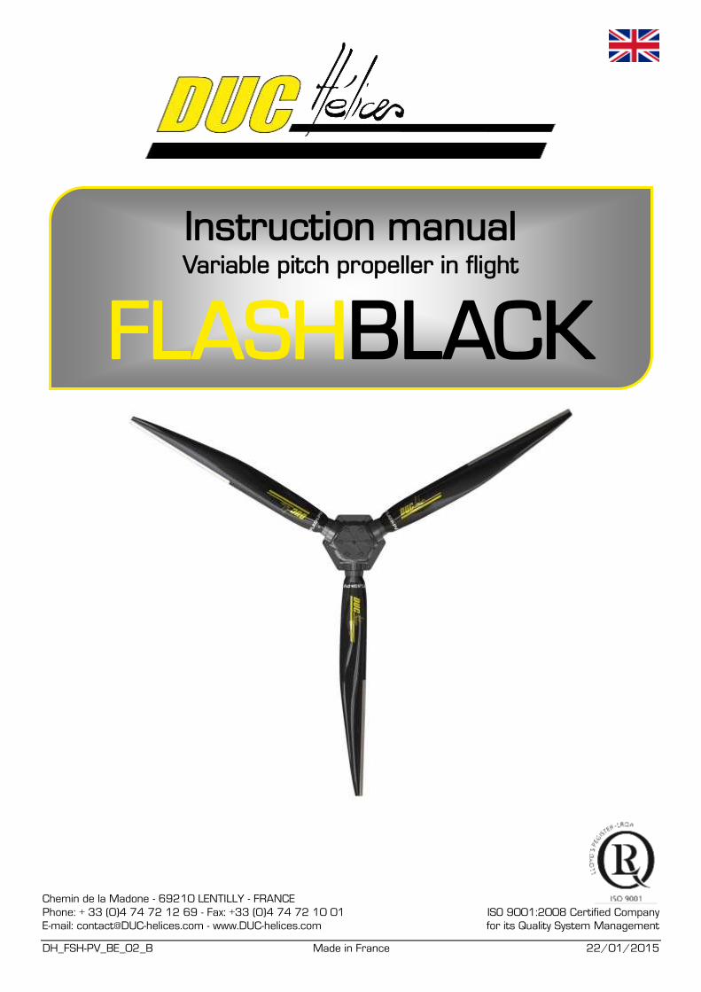
Identification
Date Delivery note n°
Owner Engine/Gearbox ratio
Aircraft Pitch range Min: Max:
Notes: ..............................................................................................................................................................................
..........................................................................................................................................................................................
..........................................................................................................................................................................................
..........................................................................................................................................................................................
..........................................................................................................................................................................................
Performances
STATIC TAKE OFF CLIMB RATE CRUISE FULL TH.
ENGINE rpm
VARIO ft/min or m/s
Distance (m) :
0 0 0 0
SPEED km/h or kt
MAP in.Hg
STATIC TAKE OFF CLIMB RATE CRUISE FULL TH.
ENGINE rpm
VARIO ft/min or m/s
Distance (m) :
0 0 0 0
SPEED km/h or kt
MAP in.Hg
STATIC TAKE OFF CLIMB RATE CRUISE FULL TH.
ENGINE rpm
VARIO ft/min or m/s
Distance (m) :
0 0 0 0
SPEED km/h or kt
MAP in.Hg
STATIC TAKE OFF CLIMB RATE CRUISE FULL TH.
ENGINE rpm
VARIO ft/min or m/s
Distance (m) :
0 0 0 0
SPEED km/h or kt
MAP in.Hg
4/50
Contents 1. Variable pitch FLASHBLACK propeller ...................................................................................................................... 5
1.1. Description ........................................................................................................................................................ 5 1.2. Characteristics .................................................................................................................................................. 5 1.3. propeller version .......................................................................................................................... 6 FLASHBLACK
1.4. Shielding leading edge in Inconel ..................................................................................................................... 6 1.5. Accessories ....................................................................................................................................................... 6 1.6. Sales reference ................................................................................................................................................. 7
2. Applications ................................................................................................................................................................ 7 3. Installation and using precautions ............................................................................................................................. 8 4. Technical data of propeller ................................................................................................................... 8 FLASHBLACK
4.1. Mounting ............................................................................................................................................................ 8 4.2. Hardware ........................................................................................................................................................... 9 4.3. Exploded view for propeller ............................................................................................................................. 10 4.4. Control receiver system .................................................................................................................................. 11 4.5. Pitch controller ................................................................................................................................................. 12 4.6. Visual indicator of pitch ................................................................................................................................... 17
5. Mounting instruction of the propeller................................................................................................... 18 FLASHBLACK
5.1. Package contents ............................................................................................................................................ 18 5.2. Operator & List of required tools ..................................................................................................................... 20 5.3. The assembly of the propeller on table ........................................................................................................... 20 5.4. Installation on the aircraft ................................................................................................................................ 23 5.5. Installation of command receiver system ........................................................................................................ 24 5.6. Installation of the hydraulic command and visual indicator ............................................................................. 27 5.7. Visual indicator of pitch ................................................................................................................................... 30 5.8. Execution of electrical wiring ........................................................................................................................... 30 5.9. Installation of the hydraulic system ................................................................................................................. 31 5.10. Finalization of propeller mounting ................................................................................................................... 38
6. Setting the small pith stop and and static tests on ground of the propeller ............................................................. 39 7. First taxi tests and then fly tests of the propeller ..................................................................................................... 42 8. Management of the failure of the variable pitch system .......................................................................................... 42 9. Installation without spinner or with spinner other than DUC .................................................................................... 42 10. Potential use & Propeller maintenance.................................................................................................................... 43
10.1. Potential use of the propeller: Unlimited ......................................................................................................... 43 10.2. Propeller maintenance schedule ..................................................................................................................... 43 10.3. Regular maintenance (by the user) ................................................................................................................. 43 10.4. General maintenance (by the user or an aeronautics workshop) ................................................................... 44 10.5. Complete maintenance (by DUC Propellers Company) ................................................................................. 44
11. General terms sale ................................................................................................................................................... 45 11.1. Ordering procedure ......................................................................................................................................... 45 11.2. Delivery ........................................................................................................................................................... 45 11.3. Price ................................................................................................................................................................ 45 11.4. Right of withdrawal .......................................................................................................................................... 45 11.5. Warranties ....................................................................................................................................................... 45 11.6. Privacy Policy .................................................................................................................................................. 45 11.7. Litigation .......................................................................................................................................................... 45
12. Annexes ................................................................................................................................................................... 46 12.1. Dimension of the ROTAX 912/912S/914 propeller-shaft ................................................................................ 46 12.2. Airfoil ............................................................................................................................................................... 46 12.3. Engine performance data’s ............................................................................................................................. 47 12.4. Operating limitation of the FLASH propeller ................................................................................................... 47 12.5. Identification marking of the propeller ............................................................................................................. 48
FLASHBLACK
5/50
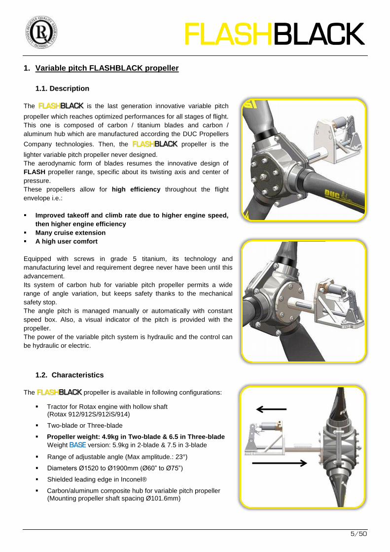
1. Variable pitch FLASHBLACK propeller
1.1. Description
The FLASH is the last generation innovative variable pitch BLACK
propeller which reaches optimized performances for all stages of flight.
This one is composed of carbon / titanium blades and carbon /
aluminum hub which are manufactured according the DUC Propellers
Company technologies. Then, the FLASH propeller is the BLACK
lighter variable pitch propeller never designed.
The aerodynamic form of blades resumes the innovative design of
FLASH propeller range, specific about its twisting axis and center of
pressure.
These propellers allow for high efficiency throughout the flight
envelope i.e.:
Improved takeoff and climb rate due to higher engine speed,
then higher engine efficiency
Many cruise extension
A high user comfort
Equipped with screws in grade 5 titanium, its technology and
manufacturing level and requirement degree never have been until this
advancement.
Its system of carbon hub for variable pitch propeller permits a wide
range of angle variation, but keeps safety thanks to the mechanical
safety stop.
The angle pitch is managed manually or automatically with constant
speed box. Also, a visual indicator of the pitch is provided with the
propeller.
The power of the variable pitch system is hydraulic and the control can
be hydraulic or electric.
1.2. Characteristics
The FLASH propeller is available in following configurations: BLACK
Tractor for Rotax engine with hollow shaft (Rotax 912/912S/912iS/914)
Two-blade or Three-blade
Propeller weight: 4.9kg in Two-blade & 6.5 in Three-blade
Weight BASE version: 5.9kg in 2-blade & 7.5 in 3-blade
Range of adjustable angle (Max amplitude.: 23°)
Diameters Ø1520 to Ø1900mm (Ø60” to Ø75”)
Shielded leading edge in Inconel®
Carbon/aluminum composite hub for variable pitch propeller (Mounting propeller shaft spacing Ø101.6mm)
6/50
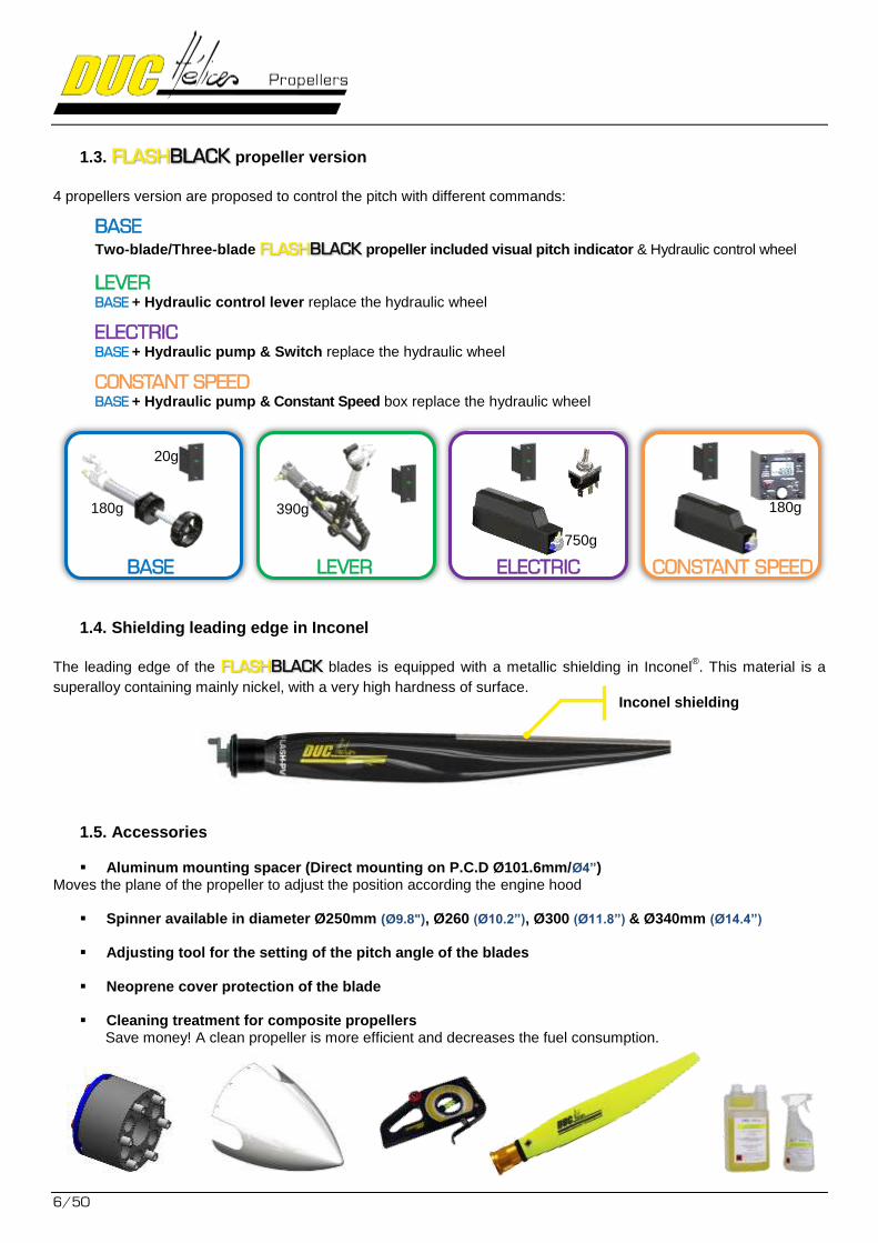
1.3. FLASH propeller version BLACK
4 propellers version are proposed to control the pitch with different commands:
BASE
Two-blade/Three-blade FLASH propeller included visual pitch indicator & Hydraulic control wheel BLACK
LEVER BASE + Hydraulic control lever replace the hydraulic wheel
ELECTRIC BASE + Hydraulic pump & Switch replace the hydraulic wheel
CONSTANT SPEED BASE + Hydraulic pump & Constant Speed box replace the hydraulic wheel
1.4. Shielding leading edge in Inconel
The leading edge of the FLASH blades is equipped with a metallic shielding in Inconel®. This material is a BLACK
superalloy containing mainly nickel, with a very high hardness of surface.
1.5. Accessories
Aluminum mounting spacer (Direct mounting on P.C.D Ø101.6mm/Ø4”) Moves the plane of the propeller to adjust the position according the engine hood
Spinner available in diameter Ø250mm (Ø9.8"), Ø260 (Ø10.2”), Ø300 (Ø11.8”) & Ø340mm (Ø14.4”)
Adjusting tool for the setting of the pitch angle of the blades
Neoprene cover protection of the blade
Cleaning treatment for composite propellers Save money! A clean propeller is more efficient and decreases the fuel consumption.
BASE CONSTANT SPEED ELECTRIC LEVER
Inconel shielding
180g
20g
390g
750g
180g
FLASHBLACK
7/50
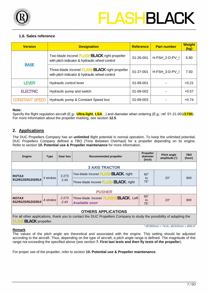
1.6. Sales reference
Version Designation Reference Part number Weight
(kg)
BASE
Two-blade Inconel FLASH right propeller BLACK
with pitch indicator & hydraulic wheel control 01-26-001 H-FSH_2-D-PV_I 5.90
Three-blade Inconel FLASH right propeller BLACK
with pitch indicator & hydraulic wheel control 01-27-001 H-FSH_3-D-PV_I 7.50
LEVER Hydraulic control lever 01-69-001 - +0.21
ELECTRIC Hydraulic pump and switch 01-69-002 - +0.57
CONSTANT SPEED Hydraulic pump & Constant Speed box 01-69-003 - +0.74
Note: Specify the flight regulation aircraft (E.g.: Ultra-light, LSA…) and diameter when ordering (E.g.: ref. 01-21-001/1730). For more information about the propeller marking, see section 12.5.
2. Applications
The DUC Propellers Company has an unlimited flight potential in normal operation. To keep the unlimited potential, DUC Propellers Company defined a TBO (Time Between Overhaul) for a propeller depending on its engine. Refer to section 10. Potential use & Propeller maintenance for more information.
Engine Type Gear box Recommended propeller Propeller diameter
(inch)
Pitch angle amplitude (°)
TBO (hour)
3 AXIS TRACTOR
ROTAX 912/912S/912iS/914
4 strokes 2.273
2.43
Two-blade Inconel FLASH , right BLACK 60’’ to
75’’ 23° 800
Three-blade Inconel FLASH , right BLACK
PUSHER
ROTAX 912/912S/912iS/914
4 strokes 2.273
2.43
Three-blade Inconel FLASH2 , Left BLACK
Available soon
60’’ to
75’’ 23° 800
OTHERS APPLICATIONS
For all other applications, thank you to contact the DUC Propellers Company to study the possibility of adapting the
FLASH propeller. BLACK* Ø1900mm = 74.8»; Ø1520mm = Ø59.8"
Remark The values of the pitch angle are theoretical and associated with the engine. This setting should be adjusted according to the aircraft. Thus, depending on the type of aircraft, a pitch angle range is defined. The magnitude of this range not exceeding the specified above (see section 7. First taxi tests and then fly tests of the propeller).
For proper use of the propeller, refer to section 10. Potential use & Propeller maintenance.
8/50
3. Installation and using precautions
RECOMMANDATION As recommended by the BRP manufacturer of Rotax engine, it’s strongly recommended to use
variable pitch FLASH propeller with an aircraft equipped with a vacuum indicator on BLACK
engine intake manifold (Pressure of the engine intake - PA) to know the engine load. Refer to your engine manual or the section 12.3 Engine performance data’s.
WARNING Make sure the ignition is turned off before starting any type of operation on the propeller. Do not run the engine without propeller, engine damage will result.
IMPORTANT - The blades of a propeller are part of a whole. DO NOT INTERCHANGE with other similar blades from propeller. The propeller blades are manufactured to their application. Their structure, weight and balance are different from a propeller to another.
- The spinner is an important element for cooling the engine. The aircraft must not fly without a spinner. Fitting a different spinner will be an addendum to this manual approved by the DUC to confirm its compatibility with the mounting of the propeller.
- The propeller is delivered with the appropriate screws. The change of the screws is contrary to our recommendations unless validated by the manufacturers.
WARRANTY CONDITIONS The user is still flying under its full responsibility (see. 6. General terms of sale).
4. Technical data of FLASH propeller BLACK
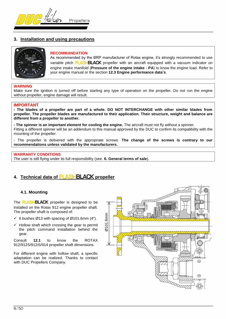
4.1. Mounting
The FLASH propeller is designed to be BLACK
installed on the Rotax 912 engine propeller shaft. The propeller shaft is composed of:
6 bushes Ø13 with spacing of Ø101.6mm (4").
Hollow shaft which crossing the gear to permit the pitch command installation behind the gear.
Consult 12.1 to know the ROTAX 912/912S/912iS/914 propeller shaft dimensions. For different engine with hollow shaft, a specific adaptation can be realized. Thanks to contact with DUC Propellers Company.
Ø101.6
mm
FLASHBLACK
9/50
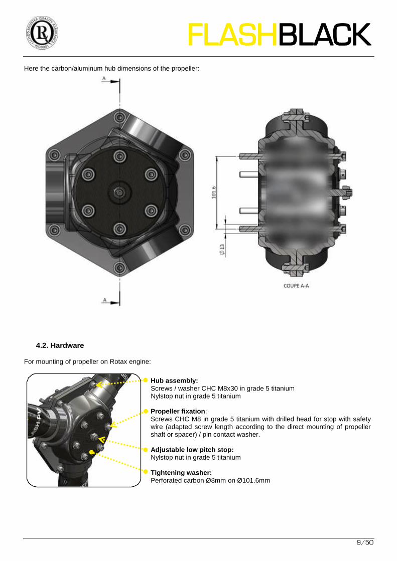
Here the carbon/aluminum hub dimensions of the propeller:
4.2. Hardware
For mounting of propeller on Rotax engine:
Hub assembly: Screws / washer CHC M8x30 in grade 5 titanium Nylstop nut in grade 5 titanium Propeller fixation: Screws CHC M8 in grade 5 titanium with drilled head for stop with safety wire (adapted screw length according to the direct mounting of propeller shaft or spacer) / pin contact washer. Adjustable low pitch stop: Nylstop nut in grade 5 titanium Tightening washer: Perforated carbon Ø8mm on Ø101.6mm
10/50
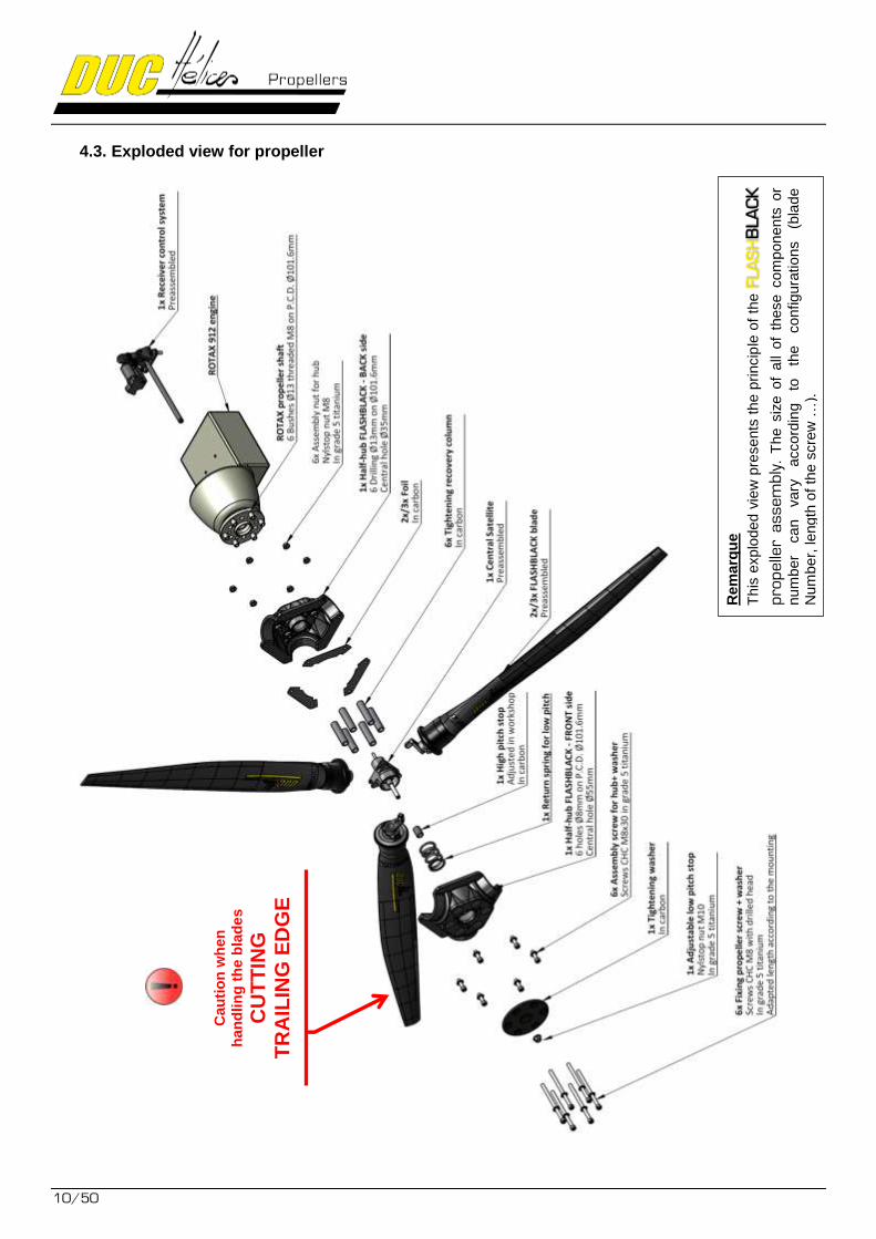
4.3. Exploded view for propeller
Cau
tio
n w
hen
han
dlin
g t
he b
lad
es
CU
TT
ING
T
RA
ILIN
G E
DG
E
Rem
arq
ue
This
explo
ded v
iew
pre
sents
the p
rincip
le o
f th
e F
LA
SH
BLA
CK
pro
pelle
r assem
bly
. T
he s
ize o
f all
of
these c
om
ponen
ts o
r
num
ber
can
vary
accord
ing
to
the
configura
tio
ns
(bla
de
Num
ber,
length
of
the
scre
w …
).
FLASHBLACK
11/50
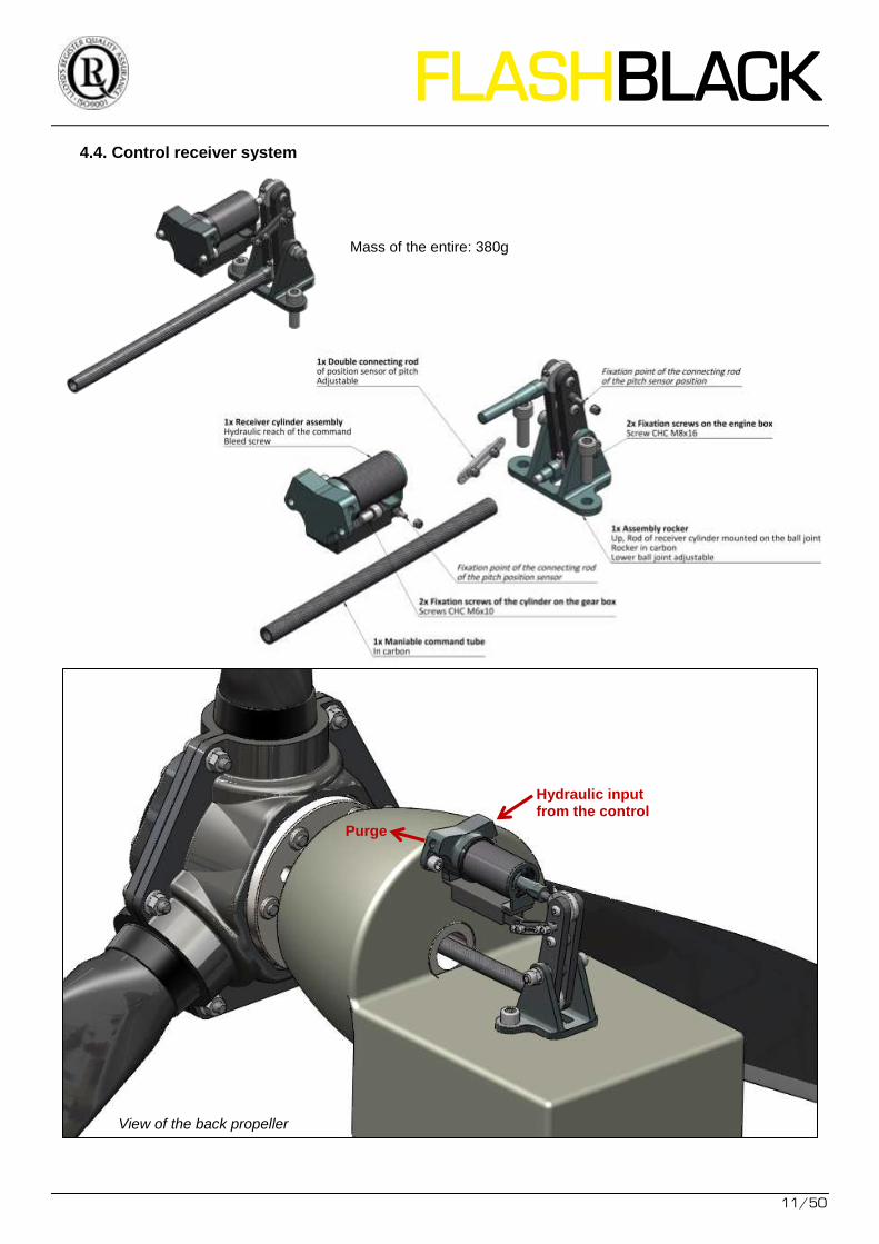
4.4. Control receiver system
Hydraulic input from the control Purge
View of the back propeller
Mass of the entire: 380g
12/50
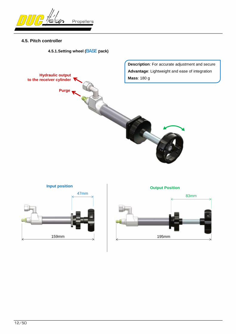
4.5. Pitch controller
4.5.1. Setting wheel (BASE pack)
Input position Output Position
47mm 83mm
Hydraulic output to the receiver cylinder
Purge
195mm 159mm
Description: For accurate adjustment and secure
Advantage: Lightweight and ease of integration
Mass: 180 g
FLASHBLACK
13/50
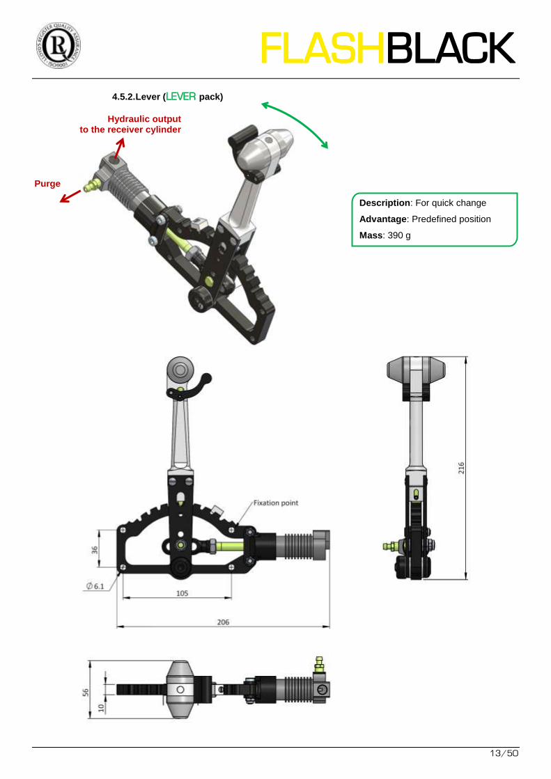
4.5.2. Lever (LEVER pack)
Hydraulic output to the receiver cylinder
Purge
Description: For quick change
Advantage: Predefined position
Mass: 390 g
14/50
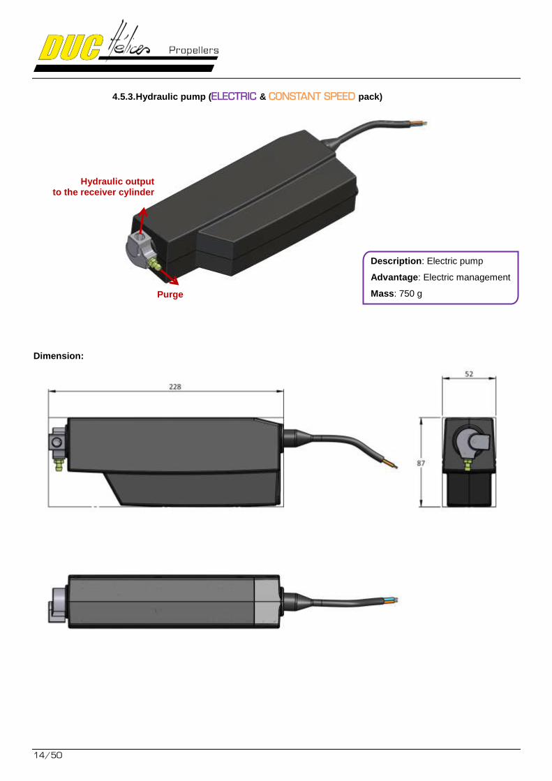
4.5.3. Hydraulic pump (ELECTRIC & CONSTANT SPEED pack)
Dimension:
Hydraulic output to the receiver cylinder
Purge
Description: Electric pump
Advantage: Electric management
Mass: 750 g
FLASHBLACK
15/50
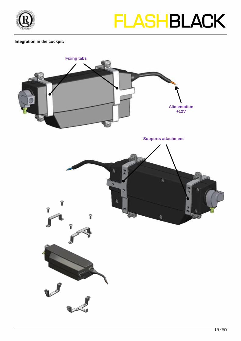
Integration in the cockpit:
Fixing tabs
Supports attachment
Alimentation +12V
16/50
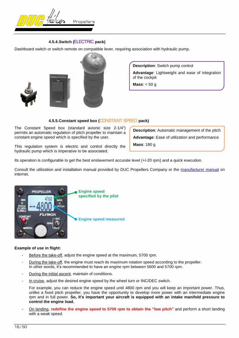
4.5.4. Switch (ELECTRIC pack)
Dashboard switch or switch remote on compatible lever, requiring association with hydraulic pump.
4.5.5. Constant speed box (CONSTANT SPEED pack)
The Constant Speed box (standard avionic size 2-1/4") permits an automatic regulation of pitch propeller to maintain a constant engine speed which is specified by the user. This regulation system is electric and control directly the hydraulic pump which is imperative to be associated. Its operation is configurable to get the best enslavement accurate level (+/-20 rpm) and a quick execution. Consult the utilization and installation manual provided by DUC Propellers Company or the manufacturer manual on internet.
Engine speed specified by the pilot Engine speed measured
Example of use in flight:
- Before the take-off, adjust the engine speed at the maximum, 5700 rpm.
- During the take-off, the engine must reach its maximum rotation speed according to the propeller. In other words, it’s recommended to have an engine rpm between 5600 and 5700 rpm.
- During the initial ascent, maintain of conditions.
- In cruise, adjust the desired engine speed by the wheel turn or INC/DEC switch.
For example, you can reduce the engine speed until 4800 rpm and you will keep an important power. Thus, unlike a fixed pitch propeller, you have the opportunity to develop more power with an intermediate engine rpm and in full power. So, it’s important your aircraft is equipped with an intake manifold pressure to control the engine load.
- On landing, redefine the engine speed to 5700 rpm to obtain the “low pitch” and perform a short landing with a weak speed.
Description: Switch pump control
Advantage: Lightweight and ease of integration of the cockpit
Mass: < 50 g
Description: Automatic management of the pitch
Advantage: Ease of utilization and performance
Mass: 180 g
FLASHBLACK
17/50
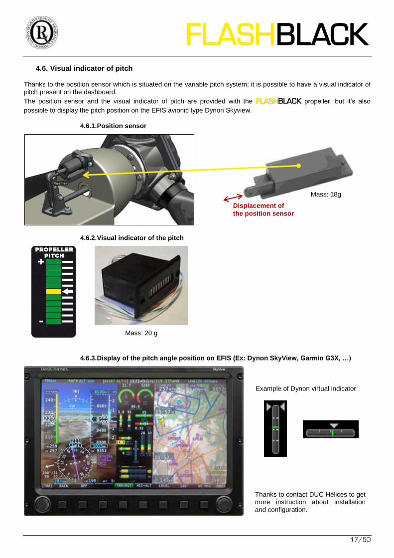
4.6. Visual indicator of pitch
Thanks to the position sensor which is situated on the variable pitch system; it is possible to have a visual indicator of pitch present on the dashboard.
The position sensor and the visual indicator of pitch are provided with the FLASH propeller, but it’s also BLACK
possible to display the pitch position on the EFIS avionic type Dynon Skyview.
4.6.1. Position sensor
4.6.2. Visual indicator of the pitch
Mass: 20 g
4.6.3. Display of the pitch angle position on EFIS (Ex: Dynon SkyView, Garmin G3X, …)
Thanks to contact DUC Hélices to get more instruction about installation and configuration.
Displacement of
the position sensor
Example of Dynon virtual indicator:
Mass: 18g
18/50
5. Mounting instruction of the FLASH propeller BLACK
The mounting of the FLASH propeller is showed hereafter. It’s recommended to assembly the propeller on a BLACK
table before to install it on the aircraft. The process is the same for the two-blade and three-blade propeller. To know more, please contact DUC Propellers Company.
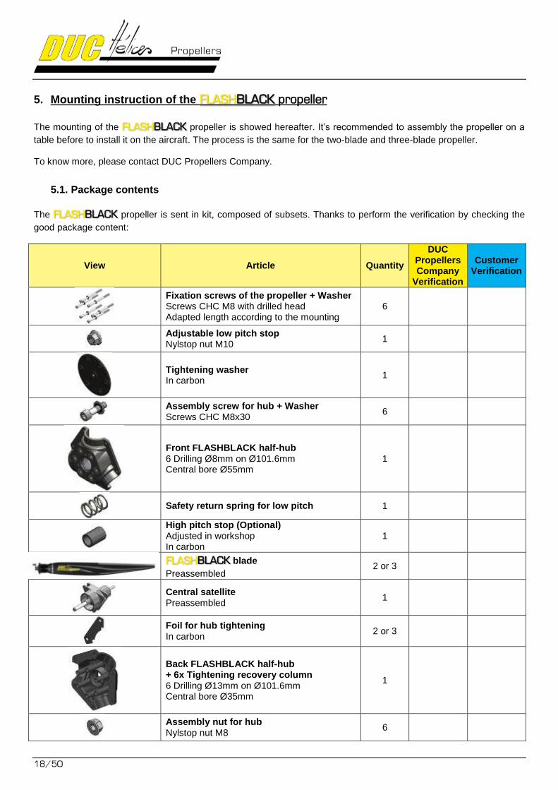
5.1. Package contents
The FLASH propeller is sent in kit, composed of subsets. Thanks to perform the verification by checking the BLACK
good package content:
View Article Quantity
DUC Propellers Company
Verification
Customer Verification
Fixation screws of the propeller + Washer Screws CHC M8 with drilled head Adapted length according to the mounting
6
Adjustable low pitch stop Nylstop nut M10
1
Tightening washer In carbon
1
Assembly screw for hub + Washer Screws CHC M8x30
6
Front FLASHBLACK half-hub 6 Drilling Ø8mm on Ø101.6mm Central bore Ø55mm
1
Safety return spring for low pitch 1
High pitch stop (Optional) Adjusted in workshop In carbon
1
FLASH blade BLACK
Preassembled 2 or 3
Central satellite Preassembled
1
Foil for hub tightening In carbon
2 or 3
Back FLASHBLACK half-hub + 6x Tightening recovery column 6 Drilling Ø13mm on Ø101.6mm Central bore Ø35mm
1
Assembly nut for hub Nylstop nut M8
6
FLASHBLACK
19/50
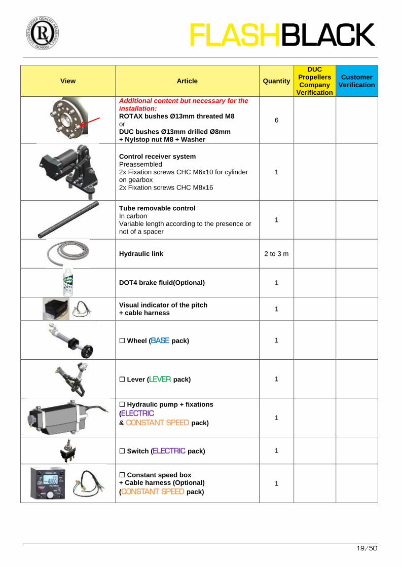
View Article Quantity
DUC Propellers Company
Verification
Customer Verification
Additional content but necessary for the installation: ROTAX bushes Ø13mm threated M8 or DUC bushes Ø13mm drilled Ø8mm + Nylstop nut M8 + Washer
6
Control receiver system Preassembled 2x Fixation screws CHC M6x10 for cylinder on gearbox 2x Fixation screws CHC M8x16
1
Tube removable control In carbon Variable length according to the presence or not of a spacer
1
Hydraulic link 2 to 3 m
DOT4 brake fluid(Optional) 1
Visual indicator of the pitch + cable harness
1
Wheel (BASE pack) 1
Lever (LEVER pack) 1
Hydraulic pump + fixations
(ELECTRIC & CONSTANT SPEED pack)
1
Switch (ELECTRIC pack) 1
Constant speed box + Cable harness (Optional)
(CONSTANT SPEED pack)
1
20/50
5.2. Operator & List of required tools
For the mounting of the propeller, it’s recommended to be 2 operators for certain operations.
Here, the list of required tools:
Dynamometric Allen key 6 (Torque: 20 and 25 Nm)
Allen key 3
2x Spanner 8
Spanner 13
Brake bleeder + Receiver bottle
Support drilled Ø30 to 50mm for the mounting of the propeller on table
Dynamometric flathead screwdriver (Torque: 4 Nm)
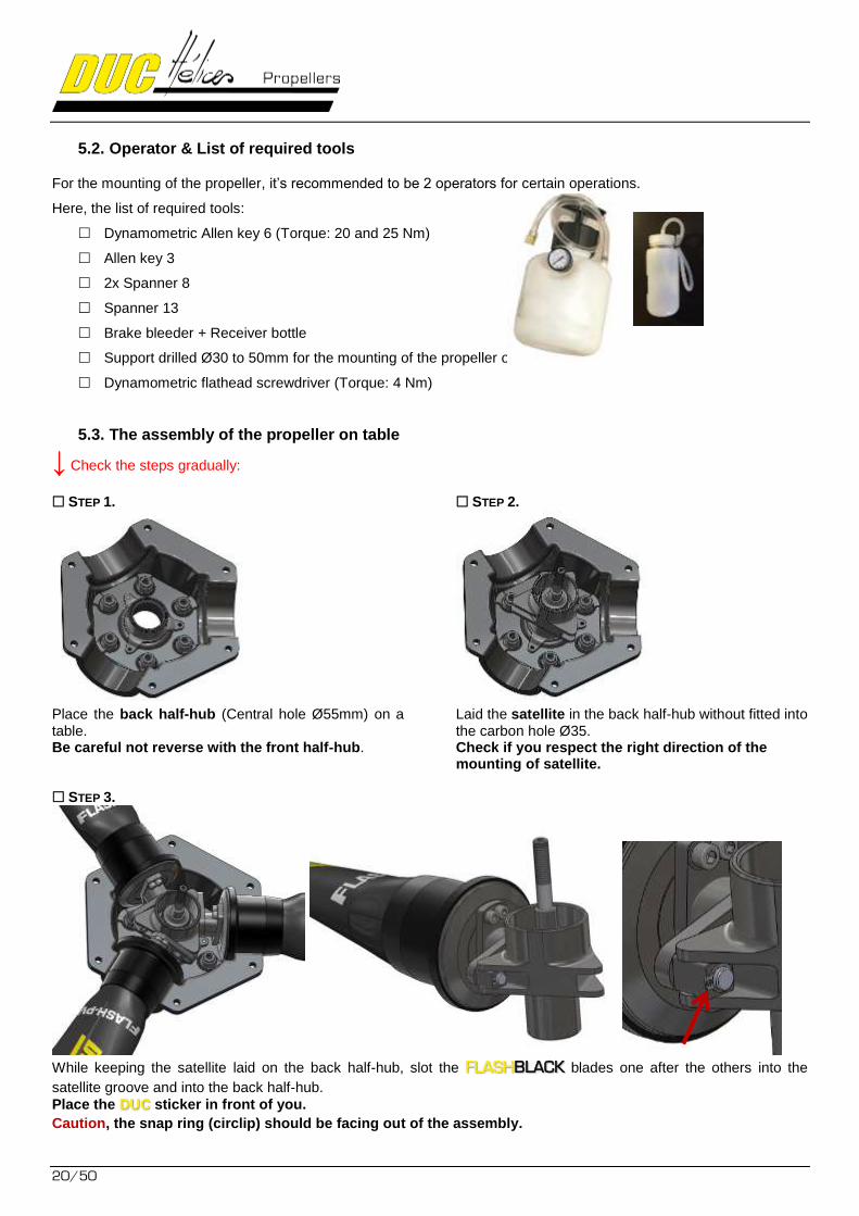
5.3. The assembly of the propeller on table
↓ Check the steps gradually:
STEP 1.
Place the back half-hub (Central hole Ø55mm) on a table. Be careful not reverse with the front half-hub.
STEP 2.
Laid the satellite in the back half-hub without fitted into the carbon hole Ø35. Check if you respect the right direction of the mounting of satellite.
STEP 3.
While keeping the satellite laid on the back half-hub, slot the FLASH blades one after the others into the BLACK
satellite groove and into the back half-hub.
Place the DUC sticker in front of you.
Caution, the snap ring (circlip) should be facing out of the assembly.
FLASHBLACK
21/50
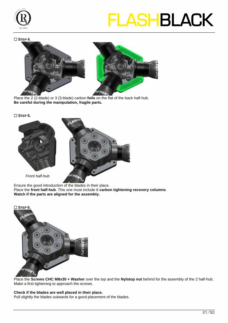
STEP 4.
Place the 2 (2-blade) or 3 (3-blade) carbon foils on the flat of the back half-hub. Be careful during the manipulation, fragile parts. STEP 5.
Ensure the good introduction of the blades in their place. Place the front half-hub. This one must include 6 carbon tightening recovery columns. Watch if the parts are aligned for the assembly. STEP 6.
Place the Screws CHC M8x30 + Washer over the top and the Nylstop nut behind for the assembly of the 2 half-hub. Make a first tightening to approach the screws. Check if the blades are well placed in their place. Pull slightly the blades outwards for a good placement of the blades.
Front half-hub
22/50
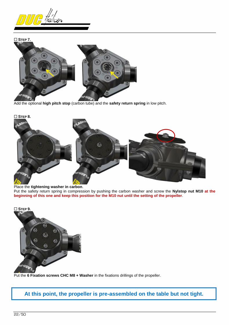
STEP 7.
Add the optional high pitch stop (carbon tube) and the safety return spring in low pitch. STEP 8.
Place the tightening washer in carbon. Put the safety return spring in compression by pushing the carbon washer and screw the Nylstop nut M10 at the beginning of this one and keep this position for the M10 nut until the setting of the propeller. STEP 9.
Put the 6 Fixation screws CHC M8 + Washer in the fixations drillings of the propeller.
At this point, the propeller is pre-assembled on the table but not tight.
FLASHBLACK
23/50
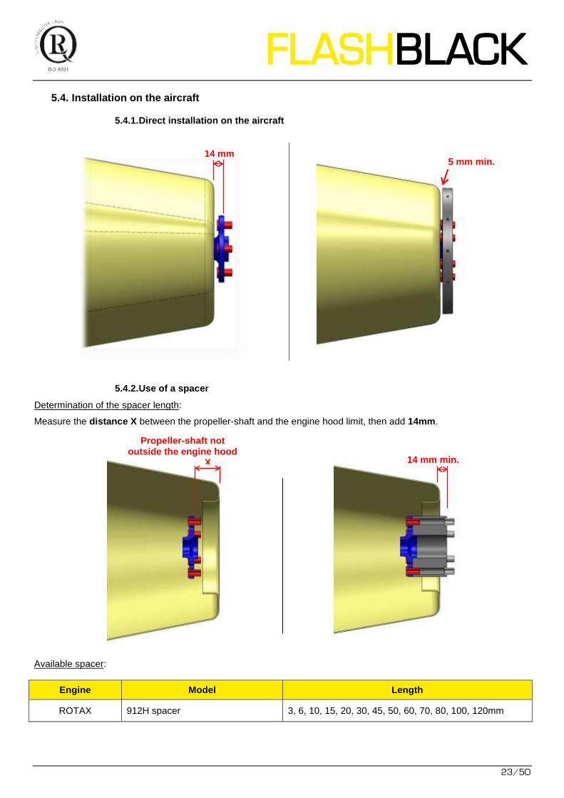
5.4. Installation on the aircraft
5.4.1. Direct installation on the aircraft
5.4.2. Use of a spacer
Determination of the spacer length:
Measure the distance X between the propeller-shaft and the engine hood limit, then add 14mm.
Available spacer:
Engine Model Length
ROTAX 912H spacer 3, 6, 10, 15, 20, 30, 45, 50, 60, 70, 80, 100, 120mm
14 mm min. 5 mm min.
Propeller-shaft not outside the engine hood
X 14 mm min.
24/50
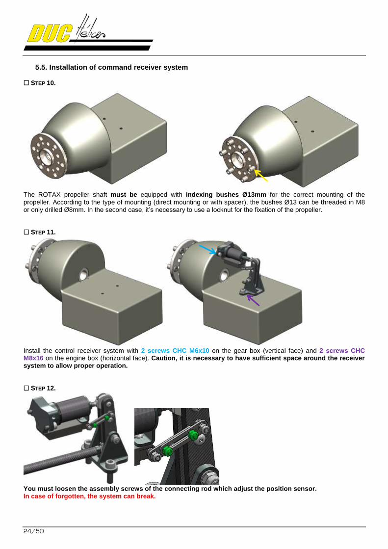
5.5. Installation of command receiver system
STEP 10.
The ROTAX propeller shaft must be equipped with indexing bushes Ø13mm for the correct mounting of the propeller. According to the type of mounting (direct mounting or with spacer), the bushes Ø13 can be threaded in M8 or only drilled Ø8mm. In the second case, it’s necessary to use a locknut for the fixation of the propeller. STEP 11.
Install the control receiver system with 2 screws CHC M6x10 on the gear box (vertical face) and 2 screws CHC M8x16 on the engine box (horizontal face). Caution, it is necessary to have sufficient space around the receiver system to allow proper operation. STEP 12.
You must loosen the assembly screws of the connecting rod which adjust the position sensor. In case of forgotten, the system can break.
FLASHBLACK
25/50
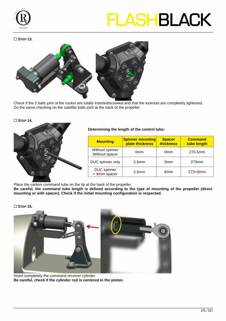
STEP 13.
Check if the 2 balls joint of the rocker are totally inserted/screwed and that the locknuts are completely tightened. Do the same checking on the satellite balls joint at the back of the propeller. STEP 14.
Determining the length of the control tube:
Mounting Spinner mounting
plate thickness Spacer
thickness Command tube length
Without spinner Without spacer
0mm 0mm 270.5mm
DUC spinner only 2.5mm 0mm 273mm
DUC spinner + Xmm spacer
2.5mm Xmm 273+Xmm
Place the carbon command tube on the tip at the back of the propeller. Be careful, the command tube length is defined according to the type of mounting of the propeller (direct mounting or with spacer). Check if the initial mounting configuration is respected. STEP 15.
Insert completely the command receiver cylinder. Be careful, check if the cylinder rod is centered in the piston.
26/50
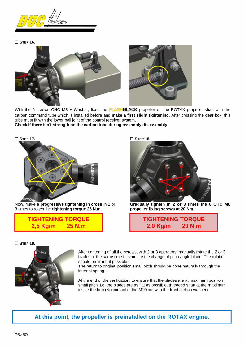
STEP 16.
With the 6 screws CHC M8 + Washer, fixed the FLASH propeller on the ROTAX propeller shaft with the BLACK
carbon command tube which is installed before and make a first slight tightening. After crossing the gear box, this tube must fit with the lower ball joint of the control receiver system. Check if there isn’t strength on the carbon tube during assembly/disassembly. STEP 17.
Now, make a progressive tightening in cross in 2 or 3 times to reach the tightening torque 25 N.m.
STEP 18.
Gradually tighten in 2 or 3 times the 6 CHC M8 propeller fixing screws at 20 Nm.
STEP 19.
After tightening of all the screws, with 2 or 3 operators, manually rotate the 2 or 3 blades at the same time to simulate the change of pitch angle blade. The rotation should be firm but possible. The return to original position small pitch should be done naturally through the internal spring. At the end of the verification, to ensure that the blades are at maximum position small pitch, i.e. the blades are as flat as possible, threaded shaft at the maximum inside the hub (No contact of the M10 nut with the front carbon washer).
At this point, the propeller is preinstalled on the ROTAX engine.
TIGHTENING TORQUE 2,5 Kg/m 25 N.m
TIGHTENING TORQUE 2,0 Kg/m 20 N.m
FLASHBLACK
27/50
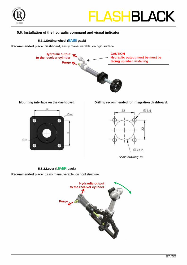
5.6. Installation of the hydraulic command and visual indicator
5.6.1. Setting wheel (BASE pack)
Recommended place: Dashboard, easily maneuverable, on rigid surface
Mounting interface on the dashboard: Drilling recommended for integration dashboard:
Scale drawing 1:1
5.6.2. Lever (LEVER pack)
Recommended place: Easily maneuverable, on rigid structure.
Hydraulic output to the receiver cylinder
Purge
Hydraulic output to the receiver cylinder
Purge
CAUTION Hydraulic output must be must be
facing up when installing
28/50
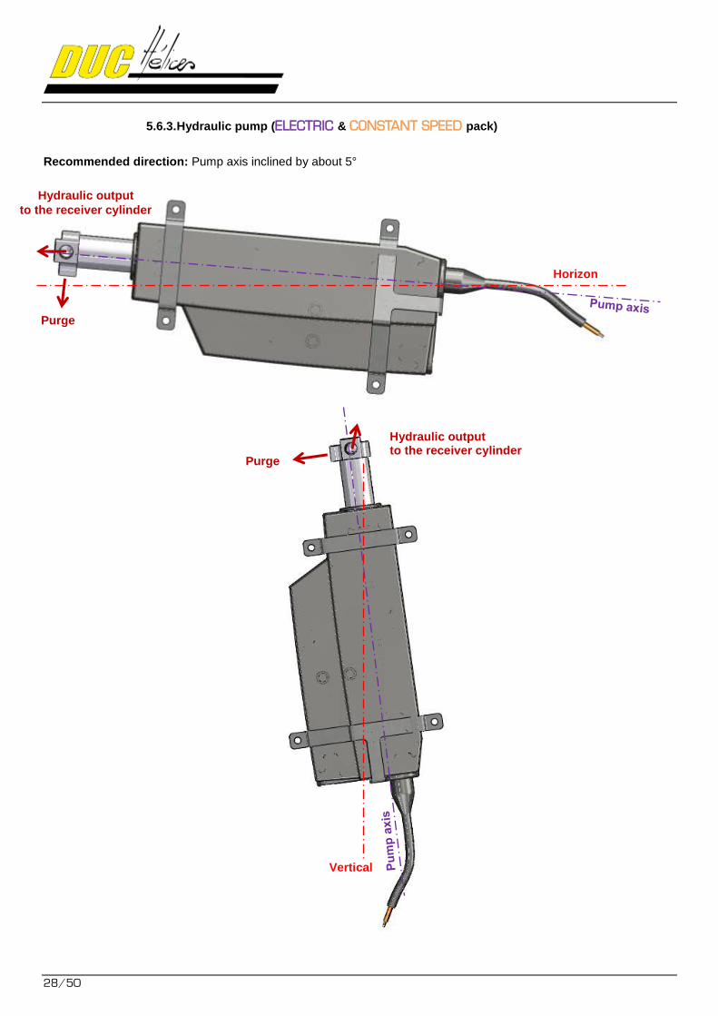
5.6.3. Hydraulic pump (ELECTRIC & CONSTANT SPEED pack)
Recommended direction: Pump axis inclined by about 5°
Hydraulic output
to the receiver cylinder
Purge
Horizon
Hydraulic output to the receiver cylinder
Purge
Vertical
FLASHBLACK
29/50
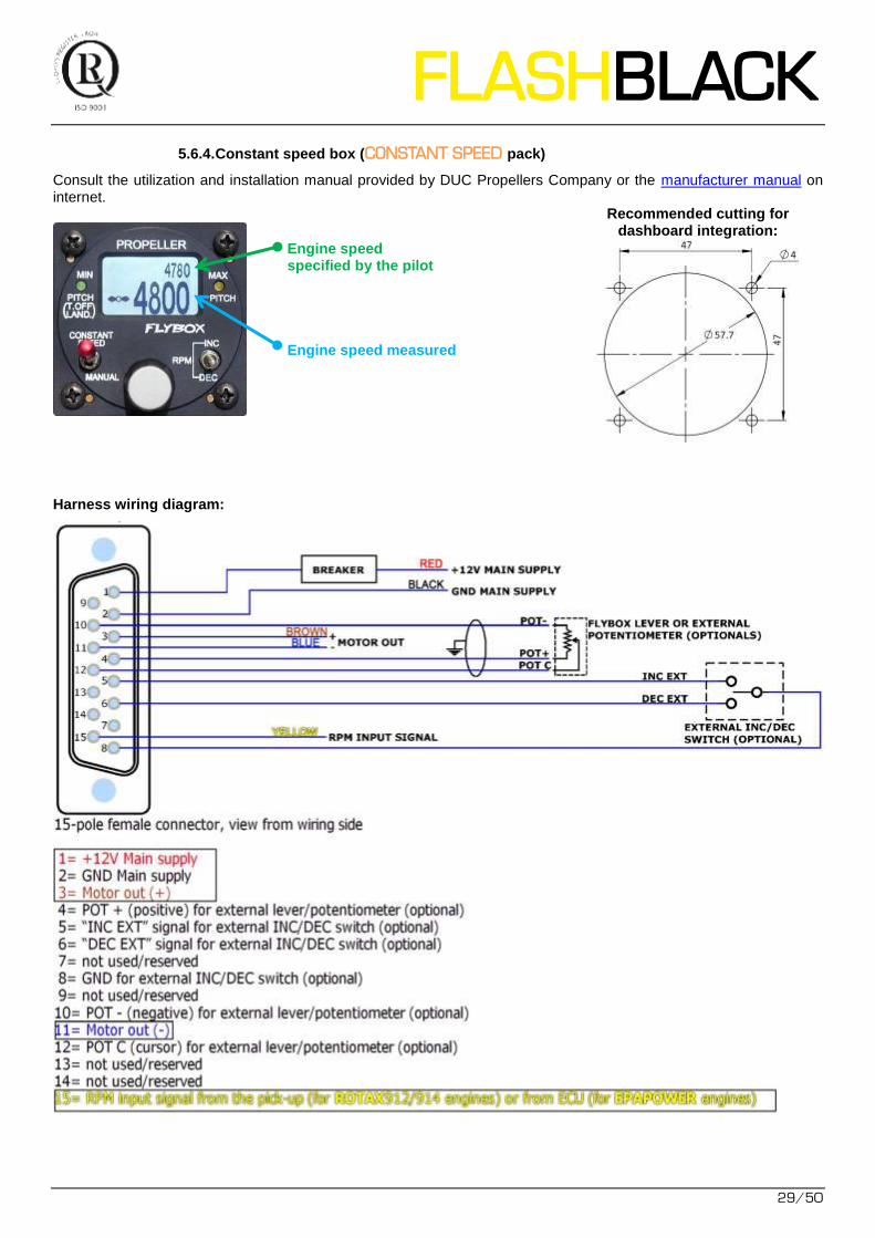
5.6.4. Constant speed box (CONSTANT SPEED pack)
Consult the utilization and installation manual provided by DUC Propellers Company or the manufacturer manual on internet.
Engine speed specified by the pilot Engine speed measured
Recommended cutting for dashboard integration:
Harness wiring diagram:
30/50
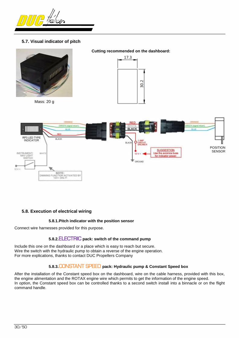
5.7. Visual indicator of pitch
Mass: 20 g
Cutting recommended on the dashboard:
5.8. Execution of electrical wiring
5.8.1. Pitch indicator with the position sensor
Connect wire harnesses provided for this purpose.
5.8.2. ELECTRIC pack: switch of the command pump
Include this one on the dashboard or a place which is easy to reach but secure. Wire the switch with the hydraulic pump to obtain a reverse of the engine operation. For more explications, thanks to contact DUC Propellers Company
5.8.3. CONSTANT SPEED pack: Hydraulic pump & Constant Speed box
After the installation of the Constant speed box on the dashboard, wire on the cable harness, provided with this box, the engine alimentation and the ROTAX engine wire which permits to get the information of the engine speed. In option, the Constant speed box can be controlled thanks to a second switch install into a binnacle or on the flight command handle.
POSITION SENSOR
FLASHBLACK
31/50
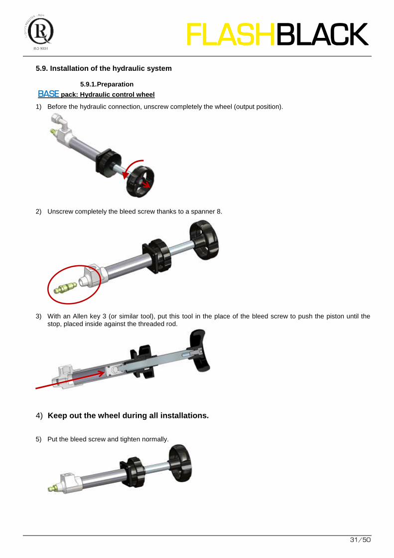
5.9. Installation of the hydraulic system
5.9.1. Preparation
BASE pack: Hydraulic control wheel
1) Before the hydraulic connection, unscrew completely the wheel (output position).
2) Unscrew completely the bleed screw thanks to a spanner 8.
3) With an Allen key 3 (or similar tool), put this tool in the place of the bleed screw to push the piston until the stop, placed inside against the threaded rod.
4) Keep out the wheel during all installations.
5) Put the bleed screw and tighten normally.
32/50
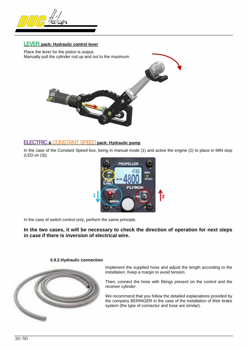
LEVER pack: Hydraulic control lever
Place the lever for the piston is output. Manually pull the cylinder rod up and out to the maximum.
ELECTRIC & CONSTANT SPEED pack: Hydraulic pump
In the case of the Constant Speed box, being in manual mode (1) and active the engine (2) to place in MIN stop (LED on (3)).
In the case of switch control only, perform the same principle.
In the two cases, it will be necessary to check the direction of operation for next steps in case if there is inversion of electrical wire.
5.9.2. Hydraulic connection
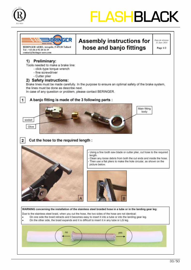
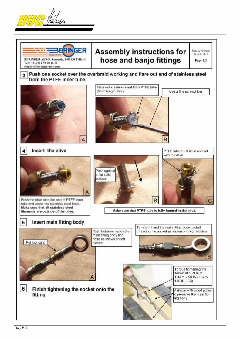
Implement the supplied hose and adjust the length according to the installation. Keep a margin to avoid tension. Then, connect the hose with fittings present on the control and the receiver cylinder. We recommend that you follow the detailed explanations provided by the company BERINGER in the case of the installation of their brake system (the type of connector and hose are similar).
1 2
3
FLASHBLACK
33/50
34/50
FLASHBLACK
35/50
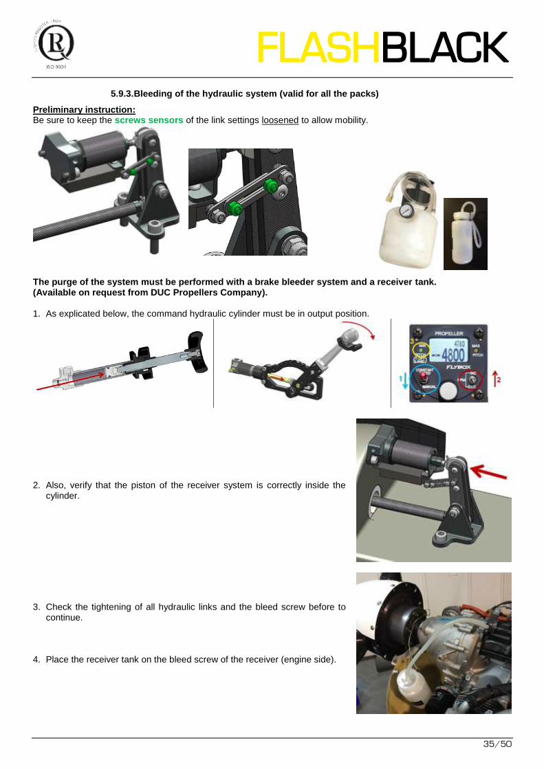
5.9.3. Bleeding of the hydraulic system (valid for all the packs)
Preliminary instruction: Be sure to keep the screws sensors of the link settings loosened to allow mobility.
The purge of the system must be performed with a brake bleeder system and a receiver tank. (Available on request from DUC Propellers Company). 1. As explicated below, the command hydraulic cylinder must be in output position.
2. Also, verify that the piston of the receiver system is correctly inside the cylinder.
3. Check the tightening of all hydraulic links and the bleed screw before to continue.
4. Place the receiver tank on the bleed screw of the receiver (engine side).
36/50
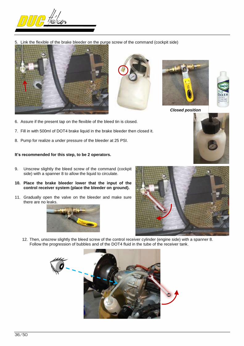
5. Link the flexible of the brake bleeder on the purge screw of the command (cockpit side)
6. Assure if the present tap on the flexible of the bleed tin is closed.
7. Fill in with 500ml of DOT4 brake liquid in the brake bleeder then closed it.
8. Pump for realize a under pressure of the bleeder at 25 PSI.
It’s recommended for this step, to be 2 operators. 9. Unscrew slightly the bleed screw of the command (cockpit
side) with a spanner 8 to allow the liquid to circulate.
10. Place the brake bleeder lower that the input of the control receiver system (place the bleeder on ground).
11. Gradually open the valve on the bleeder and make sure
there are no leaks.
12. Then, unscrew slightly the bleed screw of the control receiver cylinder (engine side) with a spanner 8. Follow the progression of bubbles and of the DOT4 fluid in the tube of the receiver tank.
Closed position
FLASHBLACK
37/50
13. As soon as the fluid no longer seems to contain bubbles, close the bleed screw of the receiver (engine side). Wait 5 to 10 seconds.
14. Then repeat the operation #12 and 13 for not having bubble present at the reopening of the bleed screw receiver cylinder (engine side).
15. Next, close the bleed screw of the command (cockpit side), and finally close the valve of the
bleeder. CAUTION, the bleeder is still under pressure.
16. Open the bleeder bottle cap to depressurize and replace the valve on open position. 17. Only now, you can remove the bleeder and the receiver tank from the installation.
You can then recover the liquid in your original container.
Do a checking of the system by operating the control. Check the right displacement of the blades and the right consistency of the direction of rotation of the blades. In the case the hydraulic pump, check the operating direction. If there is a reverse, that mean the wire is reversed and you must change it. In case of anomaly, return to the beginning with the command in output position. If the problem continues, please to contact DUC Propellers Company.
If all of these operations are well applied, the hydraulic system is purged.
It is recommended to do a last checking of all the tightening of the hydraulic fittings:
- Bleed screws
- Hydraulic links
- Fixation screws of the command and the command receiver system
38/50
5.10. Finalization of propeller mounting
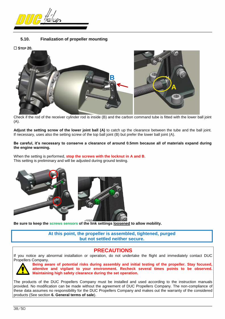
STEP 20.
Check if the rod of the receiver cylinder rod is inside (B) and the carbon command tube is fitted with the lower ball joint (A). Adjust the setting screw of the lower joint ball (A) to catch up the clearance between the tube and the ball joint. If necessary, uses also the setting screw of the top ball joint (B) but prefer the lower ball joint (A). Be careful, it’s necessary to conserve a clearance of around 0.5mm because all of materials expand during the engine warming. When the setting is performed, stop the screws with the locknut in A and B. This setting is preliminary and will be adjusted during ground testing.
Be sure to keep the screws sensors of the link settings loosened to allow mobility.
At this point, the propeller is assembled, tightened, purged but not settled neither secure.
PRECAUTIONS If you notice any abnormal installation or operation, do not undertake the flight and immediately contact DUC Propellers Company. Being aware of potential risks during assembly and initial testing of the propeller. Stay focused, attentive and vigilant to your environment. Recheck several times points to be observed. Maintaining high safety clearance during the set operation. The products of the DUC Propellers Company must be installed and used according to the instruction manuals provided. No modification can be made without the agreement of DUC Propellers Company. The non-compliance of these data assumes no responsibility for the DUC Propellers Company and makes out the warranty of the considered products (See section 6. General terms of sale).
A
B
FLASHBLACK
39/50
6. Setting the small pith stop and and static tests on ground of the propeller
RECOMMANDATION As recommended by the BRP manufacturer of Rotax engine, it’s strongly recommended to use
variable pitch FLASH propeller with an aircraft equipped with a vacuum indicator on BLACK
engine intake manifold (Pressure of the engine intake - MAP) to know the engine load. Refer to your engine manual or the section 12.3 Engine performance data’s.
The preliminary tests are important
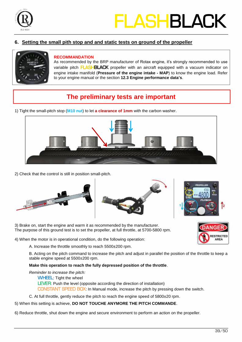
1) Tight the small-pitch stop (M10 nut) to let a clearance of 1mm with the carbon washer.
2) Check that the control is still in position small-pitch.
3) Brake on, start the engine and warm it as recommended by the manufacturer. The purpose of this ground test is to set the propeller, at full throttle, at 5700-5800 rpm. 4) When the motor is in operational condition, do the following operation:
A. Increase the throttle smoothly to reach 5500±200 rpm.
B. Acting on the pitch command to increase the pitch and adjust in parallel the position of the throttle to keep a stable engine speed at 5500±200 rpm.
Make this operation to reach the fully depressed position of the throttle.
Reminder to increase the pitch:
WHEEL: Tight the wheel
LEVER: Push the level (opposite according the direction of installation)
CONSTANT SPEED BOX: In Manual mode, increase the pitch by pressing down the switch.
C. At full throttle, gently reduce the pitch to reach the engine speed of 5800±20 rpm.
5) When this setting is achieve, DO NOT TOUCHE ANYMORE THE PITCH COMMANDE. 6) Reduce throttle, shut down the engine and secure environment to perform an action on the propeller.
40/50
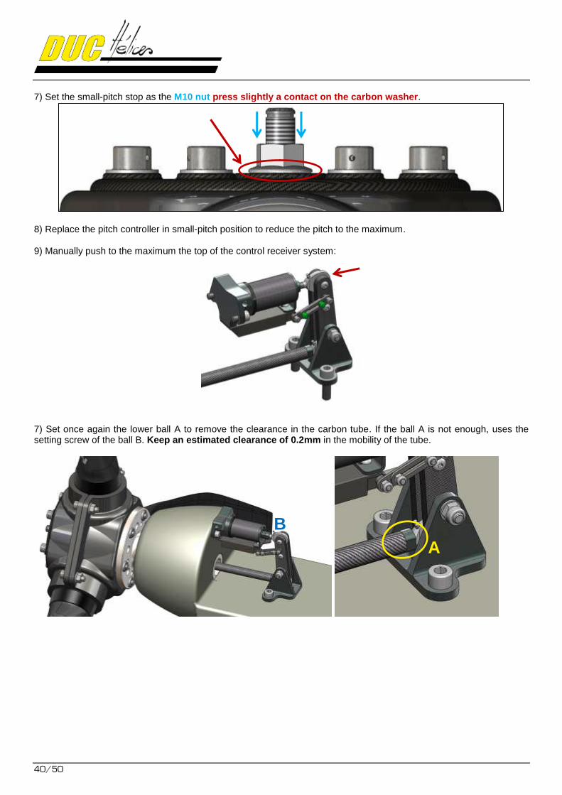
7) Set the small-pitch stop as the M10 nut press slightly a contact on the carbon washer.
8) Replace the pitch controller in small-pitch position to reduce the pitch to the maximum. 9) Manually push to the maximum the top of the control receiver system:
7) Set once again the lower ball A to remove the clearance in the carbon tube. If the ball A is not enough, uses the setting screw of the ball B. Keep an estimated clearance of 0.2mm in the mobility of the tube.
A
B

FLASHBLACK
41/50
7) Then adjust the rods of the position sensor on the receiver control system: - Retract the shaft position sensor to obtain only the first LED on - Adjusting the position of the adjustable rods. - Tighten the cap screws of these rods.
8) Finalize the static tests with a new test, engine on, by varying the engine speed and propeller pitch. For the Constant Speed box, do the specified function test specified in the FLYBOX manual.
9) When everything is set, set up the safety wire Ø0.8mm (Ø0.03") over the screw heads for safe installation.
10) After a final check (position and orientation of parts, tightening, ...), install the spinner on the spinner mounting plate by tightening the screws to a torque of 4 Nm (0.4kg / m) with the appropriate tools.
When presence of a mark, be sure to follow the indexing of the spinner from the plate.
At this point, the small-pitch stop of your FLASH propeller BLACK
is set for the first taxi tests and then fly tests). The user must perform the appropriate regulations procedures
to change the propeller in accordance with applicable regulations of the aircraft.
42/50
7. First taxi tests and then fly tests of the propeller
During the Vital Action (A-C-H-E-V-E-R) before each flight, it is recommended to check the proper functioning of the pitch variation of the propeller. Before the first flights, do a run-up to get 5600-5700 rpm. If not, change the setting of the small-pitch stop. During take-off and landing, it is imperative to set the propeller to small-pitch. In flight, changing the pitch angle by continuously monitoring the Manifold Pressure (MAP).
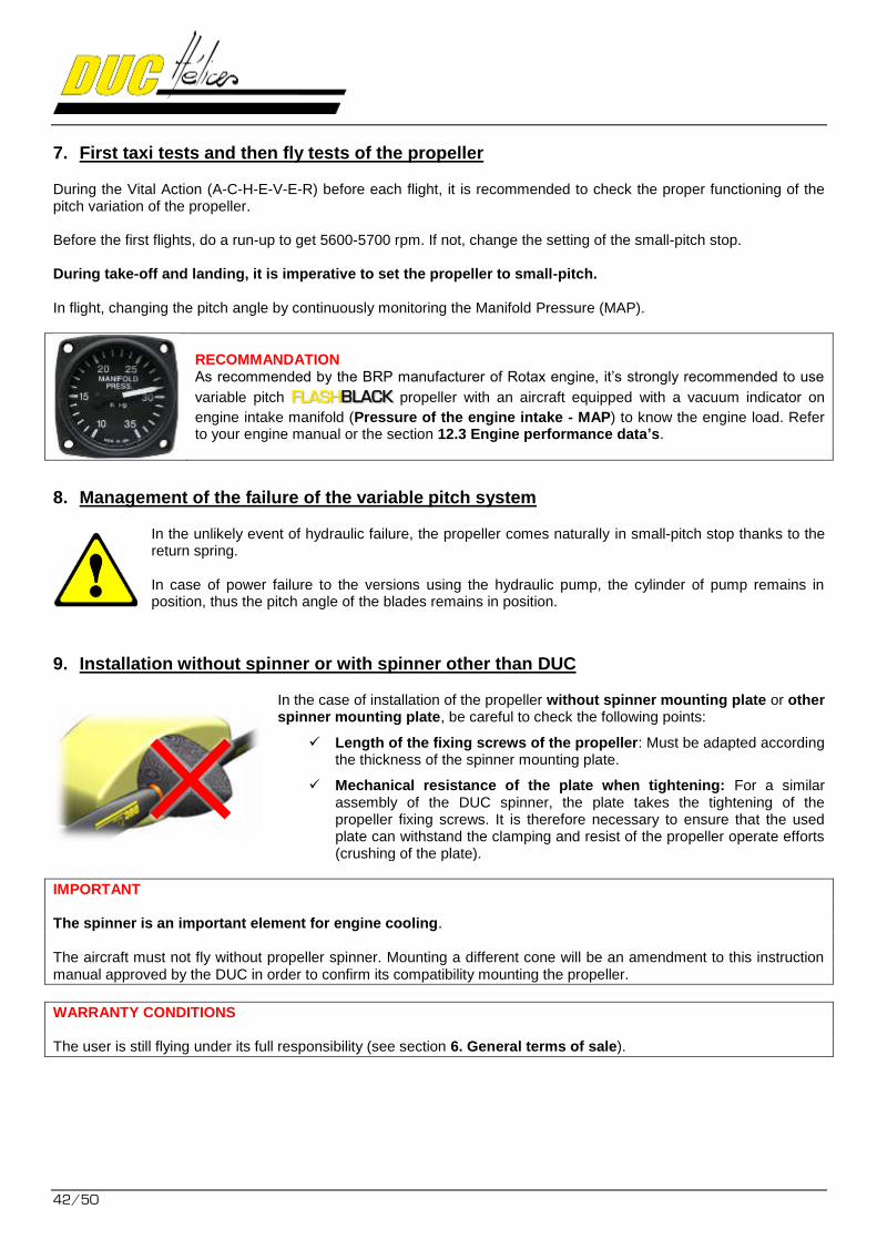
RECOMMANDATION As recommended by the BRP manufacturer of Rotax engine, it’s strongly recommended to use
variable pitch FLASH propeller with an aircraft equipped with a vacuum indicator on BLACK
engine intake manifold (Pressure of the engine intake - MAP) to know the engine load. Refer to your engine manual or the section 12.3 Engine performance data’s.
8. Management of the failure of the variable pitch system
In the unlikely event of hydraulic failure, the propeller comes naturally in small-pitch stop thanks to the return spring. In case of power failure to the versions using the hydraulic pump, the cylinder of pump remains in position, thus the pitch angle of the blades remains in position.
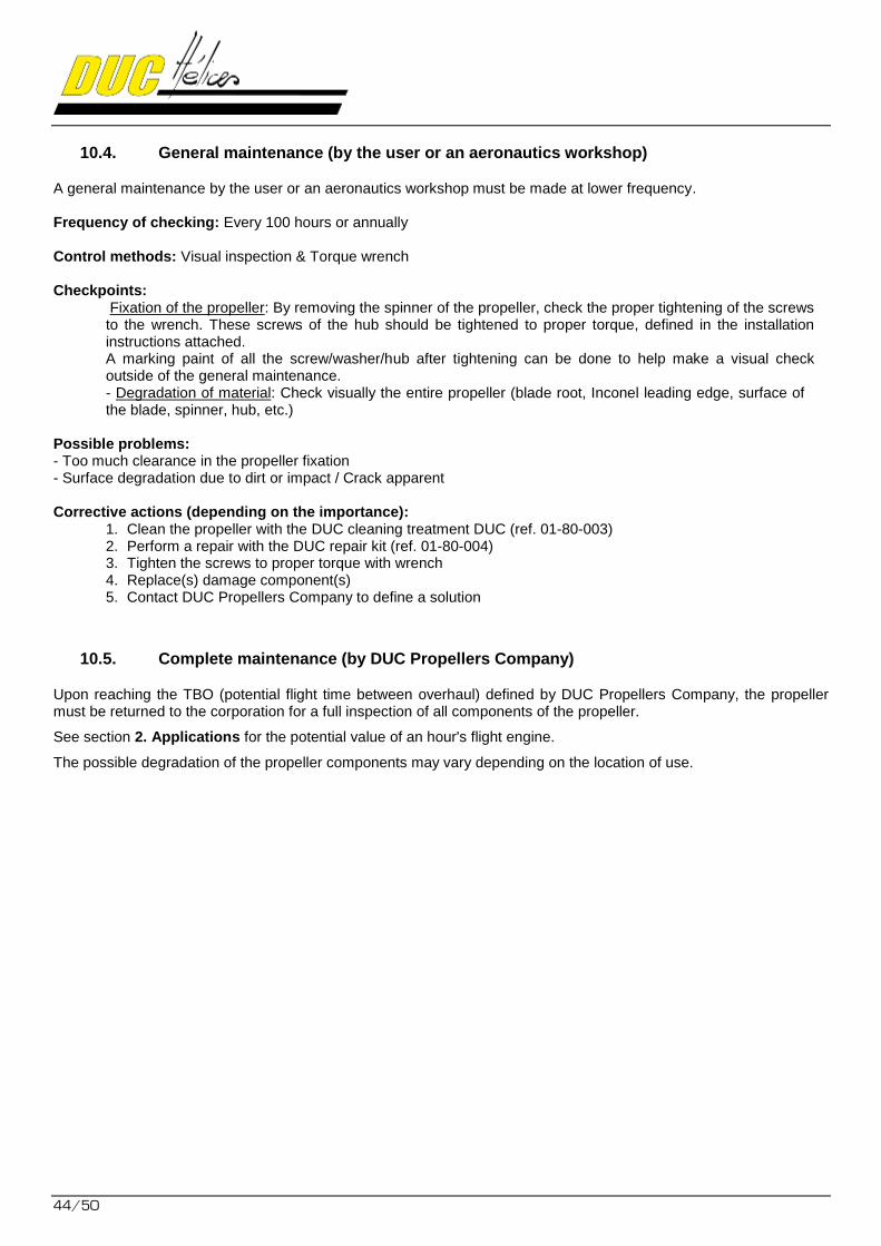
9. Installation without spinner or with spinner other than DUC
In the case of installation of the propeller without spinner mounting plate or other spinner mounting plate, be careful to check the following points:
Length of the fixing screws of the propeller: Must be adapted according the thickness of the spinner mounting plate.
Mechanical resistance of the plate when tightening: For a similar assembly of the DUC spinner, the plate takes the tightening of the propeller fixing screws. It is therefore necessary to ensure that the used plate can withstand the clamping and resist of the propeller operate efforts (crushing of the plate).
IMPORTANT The spinner is an important element for engine cooling. The aircraft must not fly without propeller spinner. Mounting a different cone will be an amendment to this instruction manual approved by the DUC in order to confirm its compatibility mounting the propeller.
WARRANTY CONDITIONS The user is still flying under its full responsibility (see section 6. General terms of sale).
FLASHBLACK
43/50
10. Potential use & Propeller maintenance
10.1. Potential use of the propeller: Unlimited
The propellers DUC have an unlimited flight potential in normal operation conditions. To keep the unlimited potential, DUC Propellers Company has defined a TBO (Time Between Overhaul) for a propeller depending on its engine. This TBO according the engine is indicated in this manual (see 2. Applications). For ROTAX engine TBO is set at 800 flight hours. In all cases, it may not exceed 5 years. To achieve this, the propeller must be returned to the DUC Propellers Company to perform a full control, verify its proper use and change the wearing parts if necessary. Following this inspection and maintenance of the propeller, the propeller is credited again with the same TBO and is returned to you. The cost of maintenance when you reach 800 hours of flight on Rotax is 800 € excl. tax, in other words 1€ per hour of flight. The deliveries costs of sending and returning will be payable by the customer. Remember, there is no imperative of logbook in light aviation. But know that this control is highly recommended for the continuing airworthiness and safety.
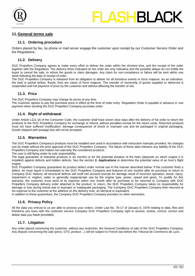
10.2. Propeller maintenance schedule
Type Actor Frequency
Regular User Each pre-flight
General user or an aeronautics workshop Every 100 hours or annually
Complete DUC Propellers Company Each TBO
10.3. Regular maintenance (by the user)
For a safety use of the FLASH propellers, it is necessary that the user performs regular maintenance to detect any abnormalities. This maintenance is usually just a simple check. Frequency of checking: Each pre-flight Control methods: Visual inspection & Manual handling Checkpoints:
- Fixation of the propeller: Manually maintaining the tip of a blade of the propeller, shake it firmly to feel if a too much clearance appears in the setting of the propeller. - Degradation of material: Check visually the entire propeller without dismantling (blade root, Inconel leading edge, surface of the blade, spinner, hub, etc.) - Fixation of the spinner: Check visually the fixation screws of the spinner. A marking paint can be made between each screw and spinner to have a means of visual inspection of proper tightening the screws.
Possible problems: - Too much clearance in the propeller fixation - Surface degradation due to dirt or impact / Crack apparent
Corrective actions (depending on the importance):
1. Clean the propeller with the DUC cleaning treatment DUC (ref. 01-80-003) 2. Perform a repair with the DUC repair kit (ref. 01-80-004) 3. Tighten the screws to proper torque with wrench 4. Replace(s) damage component(s) 5. Contact DUC Propellers Company to define a solution
44/50
10.4. General maintenance (by the user or an aeronautics workshop)
A general maintenance by the user or an aeronautics workshop must be made at lower frequency. Frequency of checking: Every 100 hours or annually Control methods: Visual inspection & Torque wrench Checkpoints:
Fixation of the propeller: By removing the spinner of the propeller, check the proper tightening of the screws to the wrench. These screws of the hub should be tightened to proper torque, defined in the installation instructions attached. A marking paint of all the screw/washer/hub after tightening can be done to help make a visual check outside of the general maintenance. - Degradation of material: Check visually the entire propeller (blade root, Inconel leading edge, surface of the blade, spinner, hub, etc.)
Possible problems: - Too much clearance in the propeller fixation - Surface degradation due to dirt or impact / Crack apparent Corrective actions (depending on the importance):
1. Clean the propeller with the DUC cleaning treatment DUC (ref. 01-80-003) 2. Perform a repair with the DUC repair kit (ref. 01-80-004) 3. Tighten the screws to proper torque with wrench 4. Replace(s) damage component(s) 5. Contact DUC Propellers Company to define a solution
10.5. Complete maintenance (by DUC Propellers Company)
Upon reaching the TBO (potential flight time between overhaul) defined by DUC Propellers Company, the propeller must be returned to the corporation for a full inspection of all components of the propeller.
See section 2. Applications for the potential value of an hour's flight engine.
The possible degradation of the propeller components may vary depending on the location of use.
FLASHBLACK
45/50
11. General terms sale
11.1. Ordering procedure
Orders placed by fax, by phone or mail server engage the customer upon receipt by our Customer Service Order and the Regulations.
11.2. Delivery
DUC Propellers Company agrees to make every effort to deliver the order within the shortest time, and the receipt of the order together with the Regulation. The delivery times indicated on the order are only indicative and the possible delays do not entitle the buyer to cancel the sale, to refuse the goods or claim damages. Any claim for non-compliance or failure will be sent within one week following the date of receipt of order. The DUC Propellers Company is released from its obligation to deliver for all fortuitous events or force majeure. As an indication, the total or partial strikes, floods, fires are cases of force majeure. The transfer of ownership of goods supplied or delivered is suspended until full payment of price by the customer and without affecting the transfer of risk.
11.3. Price
The DUC Propellers Company may change its prices at any time. The customer agrees to pay the purchase price in effect at the time of order entry. Regulation Order is payable in advance in one payment when sending the DUC Propellers Company purchase order.
11.4. Right of withdrawal
Under Article L121-16 of the Consumer Code, the customer shall have seven clear days after the delivery of his order to return the products to the DUC Propellers Company for exchange or refund, without penalties except for the return costs. Returned products must not have suffered modification, damage consequence of shock or improper use and be packaged in original packaging. Goods shipped with postage due will not be accepted.
11.5. Warranties
The DUC Propellers Company’s products must be installed and used in accordance with instruction manuals provided. No changes can be made without the prior approval of the DUC Propellers Company. The failure of these data releases any liability of the DUC Propellers Company and makes non-warranty the considered products. The user is still flying under its sole responsibility. The legal guarantee of industrial products is six months or for the potential duration of the helix (depends on which engine it is installed) against defects and hidden defects. See the section 2. Applications to determine the potential value of an hour's flight
engine. DUC Propellers Company guarantees its product defect under normal use in the manner described below: If the customer finds a defect, he must report it immediately to the DUC Propellers Company and features of one months after its purchase to return to Company DUC Helices, all structural defects will snuff into account (except for damage result of incorrect operation, shock, injury, impairment or neglect, water or generally inappropriate use by the engine type, power, speed and gear). To qualify for this warranty, the customer must send at its expense within one month after its purchase to be returned to Company with DUC Propellers Company delivery order attached to the product. In return, the DUC Propellers Company takes no responsibility for damage or loss during transit due to improper or inadequate packaging. The Company DUC Propellers Company then returned at his expense to the customer at the address on the delivery note, an identical or equivalent. In addition to these guarantees, the Company DUC Propellers Company provides no other warranties.
11.6. Privacy Policy
All the data you entrust to us are able to process your orders. Under Law No. 78-17 of January 6, 1978 relating to data, files and freedoms you have with the customer service Company DUC Propellers Company right to access, review, correct, correct and
delete data you have provided.
11.7. Litigation
Any order placed convincing the customer, without any restriction, the General Conditions of sale of the DUC Propellers Company. Any dispute concerning the sale (price, GTS, product ...) will be subject to French law before the Tribunal de Commerce de Lyon.
46/50
12. Annexes
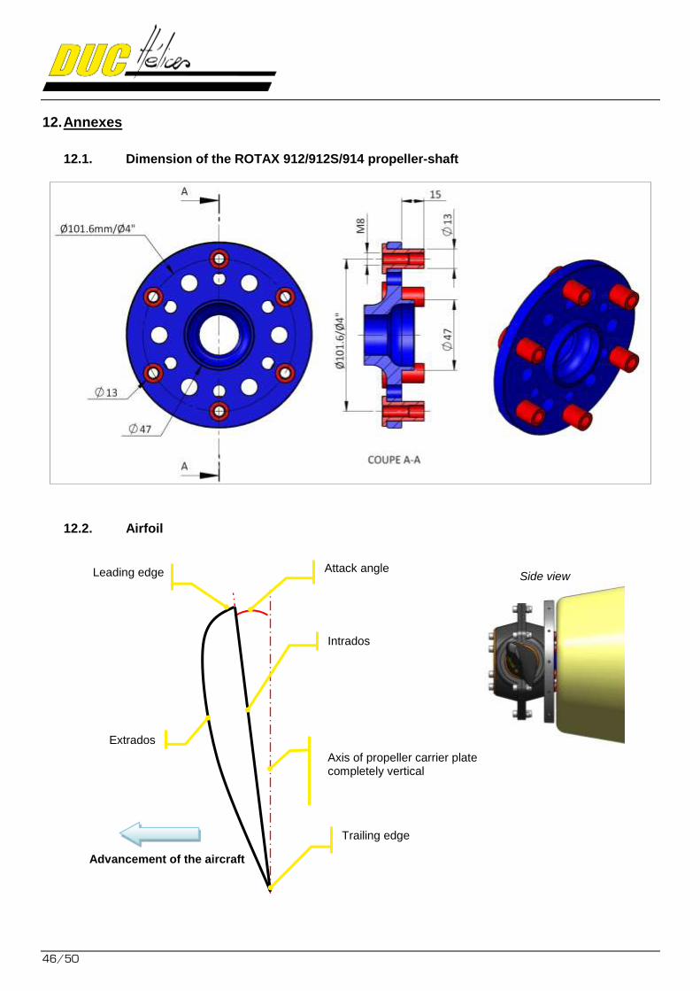
12.1. Dimension of the ROTAX 912/912S/914 propeller-shaft
12.2. Airfoil
Axis of propeller carrier plate completely vertical
Intrados
Extrados
Leading edge
Advancement of the aircraft
Trailing edge
Attack angle Side view
FLASHBLACK
47/50
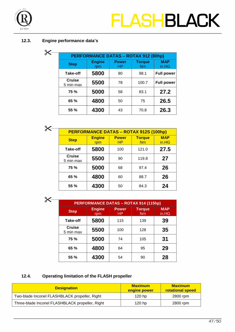
12.3. Engine performance data’s
PERFORMANCE DATAS – ROTAX 912 (80hp)
Step Engine
rpm Power
HP Torque
Nm MAP in.HG
Take-off 5800 80 98.1 Full power
Cruise 5 min max 5500 78 100.7 Full power
75 % 5000 58 83.1 27.2
65 % 4800 50 75 26.5
55 % 4300 43 70.8 26.3
PERFORMANCE DATAS – ROTAX 912S (100hp)
Step Engine
rpm Power
HP Torque
Nm MAP in.HG
Take-off 5800 100 121.0 27.5 Cruise
5 min max 5500 90 119.8 27
75 % 5000 68 97.4 26
65 % 4800 60 88.7 26
55 % 4300 50 84.3 24
PERFORMANCE DATAS – ROTAX 914 (115hp)
Step Engine
rpm Power
HP Torque
Nm MAP in.HG
Take-off 5800 115 139 39 Cruise
5 min max 5500 100 128 35
75 % 5000 74 105 31
65 % 4800 64 95 29
55 % 4300 54 90 28
12.4. Operating limitation of the FLASH propeller
Designation Maximum
engine power Maximum
rotational speed
Two-blade Inconel FLASHBLACK propeller, Right 120 hp 2800 rpm
Three-blade Inconel FLASHBLACK propeller, Right 120 hp 2800 rpm
48/50
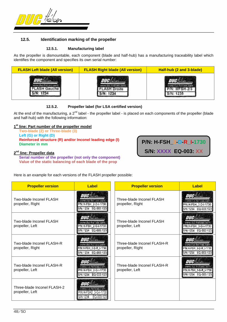
12.5. Identification marking of the propeller
12.5.1. Manufacturing label
As the propeller is dismountable, each component (blade and half-hub) has a manufacturing traceability label which identifies the component and specifies its own serial number:
FLASH Left blade (All version) FLASH Right blade (All version) Half-hub (2 and 3-blade)
12.5.2. Propeller label (for LSA certified version)
At the end of the manufacturing, a 2nd
label - the propeller label - is placed on each components of the propeller (blade and half-hub) with the following information: 1
st line: Part number of the propeller model Two-blade (2) or Three-blade (3) Left (G) or Right (D) Reinforced structure (R) and/or Inconel leading edge (I) Diameter in mm
2nd
line: Propeller data Serial number of the propeller (not only the component) Value of the static balancing of each blade of the prop
Here is an example for each versions of the FLASH propeller possible:
Propeller version Label
Propeller version Label
Two-blade Inconel FLASH propeller, Right
Three-blade Inconel FLASH propeller, Right
Two-blade Inconel FLASH propeller, Left
Three-blade Inconel FLASH propeller, Left
Two-blade Inconel FLASH-R propeller, Right
Three-blade Inconel FLASH-R propeller, Right
Two-blade Inconel FLASH-R propeller, Left
Three-blade Inconel FLASH-R propeller, Left
Three-blade Inconel FLASH-2 propeller, Left
P/N: H-FSH_3-D-R_I-1730
S/N: XXXX EQ-003: XX

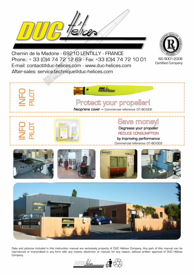
Chemin de la Madone - 69210 LENTILLY - FRANCE
Phone.: + 33 (0)4 74 72 12 69 - Fax: +33 (0)4 74 72 10 01
E-mail: [email protected] - www.duc-helices.com
After-sales: [email protected]
ISO 9001:2008
Certified Company
Data and pictures included in this instruction manual are exclusively property of DUC Hélices Company. Any part of this manual can be
reproduced or transmitted in any form with any means, electronic or manual, for any reason, without written approval of DUC Hélices
Company.
INFO
P
ILO
T
Neoprene cover – Commercial reference: 01-80-002
INFO
P
ILO
T
Degrease your propeller
REDUCE CONSUMPTION
by improving performance
Commercial reference: 01-80-003