Embed Size (px)
Citation preview

Varied Line-Space Gratings: Past, Present and Future
Michael C. Hettrick
Proc. Soc. Photo-Opt. Instr. Eng. vol. 560, pp. 96-108 (1986)
http://dx.doi.org/10.1117/12.949620
Copyright 1986 Society of Photo Optical Instrumentation Engineers. One print or electronic copy may be made for personal use only. Systematic electronic or print reproduction and distribution, duplication of any material in this paper for a fee or for commercial purposes, or modification of the content of the paper are prohibited.

Varied line -space gratings: past, present and future
Michael C. Hettrick
Lawrence Berkeley Laboratory, Center for X -Ray Optics,Building 80 -101, 1 Cyclotron Road, Berkeley, CA 94720.
Abstract
A classically ruled diffraction grating consists of grooves which are equidistant,straight and parallel. Conversely the so- called "holographic" grating ( formed by theinterfering waves of coherent visible light ) , although severely constrained by therecording wavelength and recording geometry, has grooves which are typically neitherequidistant, straight nor parallel. In contrast a varied line -space (VLS) grating, incommon nomenclature, is a design in which the groove positions are relatively unconstrainedyet possess sufficient symmetry to permit mechanical ruling. Such seemingly exotic gratingsare no longer only a theoretical curiosity, but have been ruled and used in a wide varietyof applications. These include 1) aberration -corrected normal incidence concave gratingsfor Seya -Namioka monochromators and optical de- multiplexers, 2) flat -field grazing incidenceconcave gratings for plasma diagnostics, 3) aberration -corrected grazing incidence planegratings for space -borne spectrometers, 4) focusing grazing incidence plane grating forsynchrotron radiation monochromators, and 5) wavefront generators for visible interferometryof optical surfaces (particularly aspheres). Future prospects of VLS gratings as dispersingelements, wavefront correctors and beamsplitters appear promising. I discuss the history ofVLS gratings, their present applications and their potential in the future.
Introduction
In the middle to late nineteenth century, whgn the imaging properties of the newlyconceived concave grating were being discovered , attention was already being given to theeffects of systematic variations in spacings between the grooves. The intent of thesestudies was primarily to explain anomalies observed in the spectra of imperfectly ruledgratings. For example, periodic spacing errors were found responsil2le for "ghost" linesand false images which dominated the spectra of the earliest gratings ' . Indeed, mucheffort has since been concentrated into reducing such variations and their undesirableeffects.
Cornu4 also considered the focal properties of gratings ruled with slow non -periodicvariations in groove spacings. By invoking a linear space variation ( arising from an"error of run" inherent in early ruling engines ), he was able to explain observed anomaliesin the focal curves of concave gratings, and predicted some focusing ability of a planegrating if ruled with a large linear space variation. In referring to the distance betweengrooves, quotes from two of Cornu's papers read
"J'ai en vue les erreurs systematiques qui produisent un changement de foyer sansalterer la nettete des images." (1875).
"Elle effecte, suivant le rapport existant entre R et P, des formes tres diverses,qui derivent du type de la cissoide de Diocles a laquelle d'ailleurs elle sereduit lorsque la coubure de reseau devient nulle (R= m)." (1893).
Unfortunately, the engineering challenges inherent in the fabrication of even a conventionalgrating left such possibilities dormant for the next eighty years.
During this period, the diffraction grating found use in ever more demanding circum-stances, driving the performance requirements to near perfection. Mechanical ruling5-7or optical interferometry8-10 can now form finely spaced ( up to 6000 g/mm ) grooves on thesurface of a large plane or curved surface, result in the retrieval of greater than 70%of the theoretical diffraction efficiency and with ghost line intensities negligible in mostapplications. Thus, we have reached the point where further engineering perfection of thebasic plane or concave grating will yield limited return. Significant future enhancement inthe performance of grating instruments requires that we now turn our attention to the use ofnew or unconventional geometric solutions to the problem of diffractive focusing.
Several recent technological events are seen as responsible for a growing interest inVLS gratings. First, the increased sophistication of ruling engines, which now routinelyincorporate computer control, interferometric feedback and fine servo motions; all necessaryingredients to the construction of a VLS capability. Second, the realization that aberra-tion- correction using mechanical ruling is optimal when the highest possible diffraction
96 / SP /E Vol. 560 Diffraction Phenomena in Optical Engineering Applications (1985)
Varied line-space gratings: past, present and future
Michael C. Hettrick
Lawrence Berkeley Laboratory, Center for X-Ray Optics, Building 80-101, 1 Cyclotron Road, Berkeley, CA 94720.
Abstract
A classically ruled diffraction grating consists of grooves which are equidistant, straight and parallel. Conversely the so-called "holographic" grating ( formed by the interfering waves of coherent visible light ) , although severely constrained by the recording wavelength and recording geometry, has grooves which are typically neither equidistant, straight nor parallel. In contrast a varied line-space (VLS) grating, in common nomenclature, is a design in which the groove positions are relatively unconstrained yet possess sufficient symmetry to permit mechanical ruling. Such seemingly exotic gratings are no longer only a theoretical curiosity, but have been ruled and used in a wide variety of applications. These include 1) aberration-corrected normal incidence concave gratings for Seya-Namioka monochromators and optical de-multiplexers, 2) flat-field grazing incidence concave gratings for plasma diagnostics, 3) aberration-corrected grazing incidence plane gratings for space-borne spectrometers, 4) focusing grazing incidence plane grating for synchrotron radiation monochromators, and 5) wavefront generators for visible interferometry of optical surfaces (particularly aspheres). Future prospects of VLS gratings as dispersing elements, wavefront correctors and beamsplitters appear promising. I discuss the history of VLS gratings, their present applications and their potential in the future.
Introduction
In the middle to late nineteenth century, when the imaging properties of the newly conceived concave grating were being discovered , attention was already being given to the effects of systematic variations in spacings between the grooves. The intent of these studies was primarily to explain anomalies observed in the spectra of imperfectly ruled gratings. For example, periodic spacing errors were found responsible for "ghost" lines and false images which dominated the spectra of the earliest gratings ' . Indeed, much effort has since been concentrated into reducing such variations and their undesirable effects.
Cornu also considered the focal properties of gratings ruled with slow non-periodic variations in groove spacings. By invoking a linear space variation ( arising from an "error of run" inherent in early ruling engines ), he was able to explain observed anomalies in the focal curves of concave gratings, and predicted some focusing ability of a plane grating if ruled with a large linear space variation. In referring to the distance between grooves, quotes from two of Cornu's papers read
"J'ai en vue les erreurs systematiques qui produisent un changement de foyer sans alterer la nettete des images." (1875).
"Elle effecte, suivant le rapport existant entre R et P, des formes tres diverses, qui derivent du type de la cissoide de Diocles a laquelle d'ailleurs elle se reduit lorsque la coubure de reseau devient nulle (R=~)," (1893).
Unfortunately, the engineering challenges inherent in the fabrication of even a conventional grating left such possibilities dormant for the next eighty years.
During this period, the diffraction grating found use in ever more demanding circum stances, driving the performance requirements to near perfection. Mechanical ruling^"' or optical interferometry8 ~ 10 can now form finely spaced ( up to 6000 g/mm ) grooves on the surface of a large plane or curved surface, result in the retrieval of greater than 70% of the theoretical diffraction efficiency and with ghost line intensities negligible in most applications. Thus, we have reached the point where further engineering perfection of the basic plane or concave grating will yield limited return. Significant future enhancement in the performance of grating instruments requires that we now turn our attention to the use of new or unconventional geometric solutions to the problem of diftractive focusing.
Several recent technological events are seen as responsible for a growing interest in VLS gratings. First, the increased sophistication of ruling engines, which now routinely incorporate computer control, interferometric feedback and fine servo motions; all necessary ingredients to the construction of a VLS capability. Second, the realization that aberra tion-correction using mechanical ruling is optimal when the highest possible ddffraction
96 / SPIE Vol. 560 Diffraction Phenomena in Optical Engineering Applications (1985)

efficiency is crucial or when the reduction of certain aberrations (such as coma) requiresa relatively unconstrained positioning of the grooves. Third, the use of gratings atincreasingly shorter wavelengths, particularly in the soft x -ray with the availability ofsynchrotron and plasma radiation. The line -space variations available using visible ornear UV interferometry do not closely approximate the large variations required for use atshorter wavelengths in grazing incidence. Varied line- spacing using mechanical ruling hasemerged as a preferred method of aberration -correction in the far UV, extreme UV and softx -ray bands. Fourth, spectrometers are now being designed and built for long durationspace flights in astronomy. Requirements on physical compactness, efficiency and signal -to-noise are extreme, and are increasingly being met by exploiting the extra degree of freedomavailable with varied line -spacing. Such designs have revitalized the use of unconventional .plane grating geometries in both astronomical spectrometers and laboratory monochromators.Fifth, the development of high -resolution photoelectric detectors (microchannel plates,imaging proportional counters, streak cameras, etc) for which the spectrum is imaged on aflat detecting surface. Varied spacings on a grazing incidence grating can be used toobtain such required flat -field imaging. Finally, the fabrication of precisely shapedaspheric surfaces (e.g. grazing incidence telescopes, toroids, normal incidence paraboloids)has precipitated the need for more exacting methods of surface metrology. VLS gratings,including the use of circular grooves, have been used to generate wavefronts suitable forthe interferometric testing of figured optical surfaces. Thus, we see a broad range ofneeds have arisen in which VLS gratings are crucial elements.
In this paper, I have made an attempt to briefly review any work published on thesubject of VLS gratings, survey their current applications, and speculate as to the futureroles such devices may assume. The following sections discuss various relaxations of theclassical constraints on grating design. First we consider gratings in which the groovesare straight and parallel, but not equidistant. Second we consider equally curved orconcentrically curved grooves which may be either equally or unequally spaced. Lastly wediscuss gratings in which the grooves are straight, but are not parallel and thus must alsohave space variations. In all three categories we find both plane grating and concavegrating surfaces have been utilized.
Non -equidistant, straight and parallel rulings
Concave Surfaces
In the literal sense, a curved surface contains curved grooves. The phrase "straightand parallel rulings" refers to the conventional rectilinear motion of a mechanical rulingengine for which the grooves are formed at the intersection of the grating surface and a setof parallel planes in which the tool reciprocates. Any modern ruling engine can thus, inprinciple, be outfitted with means of specifying the location of individual grooves in thisgeometry. As such, these were the first VLS gratings studied and fabricated.
In a series of papers from 1875 to 1893, Cornu investigated in some detail the anomalousfocal curves which result from linear space variations, i.e. a = a + w da /dw, where a isthe nominal spacing, w is the ruled width coordinate and the derivative da /dw is a cons ?ant.He arrived at the following equation for the spectral (meridional) focal curve:
p = costa / (cosa /R - sina /P) (1)
where R is the grating radius of curvature, P = o /( da /dw), a is the angle of diffraction(or incidence) and p is the image distance measured from the grating center. A perfectlyruled classical concave grating has an infinite value for P, which from the above equationresults in the Rowland circle p = R cosa. Small space variations mainly tilt the Rowlandcircle in the direction of larger groove spacings.However, a significant space variation, for which
Fig. 1. Anomalous focal curve of Cornu (1893). Fig. 2. Remuniscate of Sakayanagi (1967).
SP /E Vol 560 Diffraction Phenomena in Optical Engineering Applications (1985) / 97
efficiency is crucial or when the reduction of certain aberrations (such as coma) requires a relatively unconstrained positioning of the grooves. Third, the use of gratings at increasingly shorter wavelengths, particularly in the soft x-ray with the availability of synchrotron and plasma radiation. The line-space variations available using visible or near UV interferometry do not closely approximate the large variations required for use at shorter wavelengths in grazing incidence. Varied line-spacing using mechanical ruling has emerged as a preferred method of aberration-correction in the far UV, extreme UV and soft x-ray bands. Fourth, spectrometers are now being designed and built for long duration space flights in astronomy. Requirements on physical compactness, efficiency and signal-to- noise are extreme, and are increasingly being met by exploiting the extra degree of freedom available with varied line-spacing. Such designs have revitalized the use of unconventional plane grating geometries in both astronomical spectrometers and laboratory monochromators. Fifth, the development of high-resolution photoelectric detectors (microchannel plates, imaging proportional counters, streak cameras, etc) for which the spectrum is imaged on a flat detecting surface. Varied spacings on a grazing incidence grating can be used to obtain such required flat-field imaging. Finally, the fabrication of precisely shaped aspheric surfaces (e.g. grazing incidence telescopes, toroids, normal incidence paraboloids) has precipitated the need for more exacting methods of surface metrology. VLS gratings, including the use of circular grooves, have been used to generate wavefronts suitable for the interferometric testing of figured optical surfaces. Thus, we see a broad range of needs have arisen in which VLS gratings are crucial elements.
In this paper, I have made an attempt to briefly review any work published on the subject of VLS gratings, survey their current applications, and speculate as to the future roles such devices may assume. The following sections discuss various relaxations of the classical constraints on grating design. First we consider gratings in which the grooves are straight and parallel, but not equidistant. Second we consider equally curved or concentrically curved grooves which may be either equally or unequally spaced. Lastly we discuss gratings in which the grooves are straight, but are not parallel and thus must also have space variations. In all three categories we find both plane grating and concave grating surfaces have been utilized.
Non-equidistant, straight and parallel rulings
Concave Surfaces
In the literal sense, a curved surface contains curved grooves. The phrase "straight and parallel rulings" refers to the conventional rectilinear motion of a mechanical ruling engine for which the grooves are formed at the intersection of the grating surface and a set of parallel planes in which the tool reciprocates. Any modern ruling engine can thus, in principle, be outfitted with means of specifying the location of individual grooves in this geometry. As such, these were the first VLS gratings studied and fabricated.
In a series of papers from 1875 to 1893, Cornu investigated in some detail the anomalous focal curves which result from linear space variations, i.e. a = a + w da/dw, where a is the nominal spacing, w is the ruled width coordinate and the deriva?ive da/dw is a constant. He arrived at the following equation for the spectral (meridional) focal curve:
p = cos a / (cosa /R sina /P) (1)
where R is the grating radius of curvature, P = a /( da/dw), a is the angle of diffraction (or incidence) and p is the image distance measured from the grating center. A perfectly ruled classical concave grating has an infinite value for P, which from the above equation results in the Rowland circle p = R cosa. Small space variations mainly tilt the Rowland circle in the direction of larger groove spacings. However, a significant space variation, for which
Fig. 1. Anomalous focal curve of Cornu (1893). Fig. 2. Remuniscate of Sakayanagi (1967).
SPIE Vol. 560 Diffraction Phenomena in Optical Engineering Applications (1985) / 97

P is comparable to R, results in a non -closed focal surface reproduced in Fig. 1.
Apparently unaware of Cornu's work, Sakayanagi proposed in 1967 that a concave sphericalgrating be ruled with varied groove spacingsll. Sakayanagi realized the potential of spacevariations in removing aberrations in the image *. With an approximately linear variation,defined by P =2R in eqn. 1, he generated a reminuscate meridional focal curve which wouldbe tangent to the sagittal (secondary) focal plane at a point in whose vicinity astigmatismwould be small (Fig. 2). The paper of Sakayanagi marks the beginning of an era whenfabrication of VLS gratings became practical.
In 1970, Gerasimov et al13, 14devised a ruling engine
N a
capable of introducing fixed variations in the groovespacings. Their setup consisted of a grating interfero-meter within which was inserted a cam -driven screen whichmodulated the moire fringes according to the cam shape.Using a circular cam, they ruled several plane and concavegratings with linear space variations (of order 1 %). InFig. 3 are shown imaging tests of three concave gratings i
using a mercury light source and an entrance slit whichwas broken in height to test for astigmatism removal. Thegratings had a radius of 1 meter and were mounted nearnormal incidence resulting in focal curves as illustrated 'o
below the spectra. The removal of astigmatism within abroad wavelength range centered at the intersection pointof the distorted meridional curve and the sagittal planewas verified. Curve 4 in Fig. 3 shows the Rowland circle.It is historically interesting to note that this first Fig. 3. Reduction of astigmatismdemonstration of a mechanically ruled aberration -corrected demonstrated by Gerasimov(1970).grating occurred within the same time period in whichholographic corrections were first demonstrated on photoresist gratings
The first instrument which effectively used a VLS mechanically ruled grating appggrs tohave been a far UV solar spectrograph flown on the Skylab space observatory in 1973'. Themain grating of the spectrograph was preceded by a cross- disperser concave grating whichdecreased the level of focused stray light and extended the wavelength range by separatingspectral orders 1 and 2 of the main grating. However another function of this predisperserwas to correct for the astigmatism (2 -3 mm) of the main grating. As shown in Fig. 4, the
disperser was ruled in ten segments (multi -partite) acrossits ruled width, each segment having a discrete groovespacing. Although not continuous, this variation changedits meridional focal surface to approximate the sagittalplane (Sirk's position) of the main grating (POINT C).Astigmatism in the main spectrum was reduced a factor ofthree, and the recording speed of the spectrograph therebyincreased. The segmented predisperser was ruled byB.W. Bach while at Bausch and Lomb. The instrumentrecorded 6400 spectra during its flight on Skylab (Fig.5).
r
RRECiSRERSER SAGITTAL FOCAL PLANE
PREDISPERSEP TANGENTIAL FOC ALPLANE ROWLAND CIRCLE I
PLANE OF MAIN GRATINGPOI, AND CIRCLE
Fig.4. Bartoe segmented predisperser
1
LIMB - 12 ARCSECQUIET REGION
LIMB-12 ARCSECVI) 11110 4 ip ACTIVE REGION
LIMBMM M M*4,I 94 $101 4)" FLARE
I 11OFF -LIMB +2 ARCSECQUIET REGION
OFF -LIMB +2 ARCSEC141 $14014$ 41 011) +oil NI) 11)14 0011 ACTIVE REGION
'n 1530' 351 115401 ',3 Ißó ence signal to correct the blank translation byN m
means of a servo motor driven in pulsed steps of" 0.2 R. Harada has demonstrated systematic
Fig.5. Skylab solar spectra, astigmatism control of the groove positions to less than 1 á0.5 mm, A /Aa ti 15,000. From Bartoe (1974). in a coma -corrected VUV Seya- Namioka grating
whose total required space variation was only2 R. This accuracy should be understood as a statistical uncertainty averaged over thenumber of grooves necessary to construct an interference pattern of the observed resolution.
(1974) .The most significant advances in the engineer-
ing realization and practical use of the VLSconcave grating have been made over the lastdecade by Harada and colleagues at Hitachi'sCentral Research Laboratory. They have con-structed ruling engines capable of placinggrooves according to essentially any desiredinput function continuously across the gratingruled width (Fig. 6)17 -19. Their control system(Fig. 7) consists of a multi -reflection prisminterferometer which can determine position ofthe grating blank to a small fraction of thelaser wavelength. The desired space variationis input by microcomputer and used as a refer-
A thesis by Baumgardner also investigated VLS gratings and found similar results.
98 / SP /E Vol. 560 Diffraction Phenomena in Optical Engineering Applications (1985)
P is comparable to R, results in a non-closed focal surface reproduced in Fig. 1.
Apparently unaware of Cornu's work, Sakayanagi proposed in 1967 that a concave spherical grating be ruled with varied groove spacingsll. Sakayanagi realized the potential of space variations in removing aberrations in the image*. With an approximately linear variation, defined by P=2R in eqn. 1, he generated a reminuscate meridional focal curve which would be tangent to the sagittal (secondary) focal plane at a point in whose vicinity astigmatism would be small (Fig. 2). The paper of Sakayanagi marks the beginning of an era when fabrication of VLS gratings became practical.
In 1970, Gerasimov et al ' devised a ruling engine capable of introducing fixed variations in the groove spacings. Their setup consisted of a grating interfero meter within which was inserted a cam-driven screen which modulated the moire fringes according to the cam shape. Using a circular cam, they ruled several plane and concave gratings with linear space variations (of order 1%). In Fig. 3 are shown imaging tests of three concave gratings using a mercury light source and an entrance slit which was broken in height to test for astigmatism removal. The gratings had a radius of 1 meter and were mounted near normal incidence resulting in focal curves as illustrated below the spectra. The removal of astigmatism within a broad wavelength range centered at the intersection point of the distorted meridional curve and the sagittal plane was verified. Curve 4 in Fig. 3 shows the Rowland circle. It is historically interesting to note that this first demonstration of a mechanically ruled aberration-corrected grating occurred within the same time period in which
Fig. 3. Reduction of astigmatism demonstrated by Gerasimov(1970).
holographic corrections were first demonstrated on photoresist gratings 15
M
The first instrument which effectively used a VLS mechanically ruled grating appears to have been a far UV solar spectrograph flown on the Skylab space observatory in 1973 . The main grating of the spectrograph was preceded by a cross-disperser concave grating which decreased the level of focused stray light and extended the wavelength range by separating spectral orders 1 and 2 of the main grating. However another function of this predisperser was to correct for the astigmatism (2-3 mm) of the main grating. As shown in Fig. 4, the
disperser was ruled in ten segments (multi-partite) across its ruled width, each segment having a discrete groove spacing. Although not continuous, this variation changed its meridional focal surface to approximate the sagittal plane (Sirk's position) of the main grating (POINT C). Astigmatism in the main spectrum was reduced a factor of three, and the recording speed of the spectrograph thereby increased. The segmented predisperser was ruled by B.W. Bach while at Bausch and Lomb. The instrument
Row^c.RCLE 1'" 1111 '' recorded 6400 spectra during its flight on Skylab (Fig. 5).
Fig. 4. Bartoe segmented predisperser (1974). , . _. , , j_u^ ^ * r \ i The most significant advances in the engineer ing realization and practical use of the VLS concave grating have been made over the last decade by Harada and colleagues at Hitachi's Central Research Laboratory. They have con structed ruling engines capable of placing grooves according to essentially any desired input function continuously across the grating ruled width (Fig. 6) 17 "" 19 . Their control system (Fig. 7) consists of a multi-reflection prism interferometer which can determine position of the grating blank to a small fraction of the laser wavelength. The desired space variation is input by microcomputer and used as a refer ence signal to correct the blank translation by means of a servo motor driven in pulsed steps of 0.28. Harada has demonstrated systematic control of the groove positions to less than 1 A in a coma-corrected VUV Seya-Namioka grating whose total required space variation was only
2 8. This accuracy should be understood as a statistical uncertainty averaged over the number of grooves necessary to construct an interference pattern of the observed resolution.
*A thesis by Baumgardner12 also investigated VLS gratings and found similar results.
$$
I MMl
LIMB-12 ARCSEC QUIET REGION
LIMB-12 ARCSEC ACTIVE REGION
LIMB FLARE
OFF-LIMB -1-2 ARCSEC QUIET REGION
OFF-LIMB +2 ARCSEC ACTIVE REGION
i I i i 1550
Fig.5. Skylab solar spectra, astigmatism 0.5 mm, X/AX ^ 15,000. From Bartoe (1974).
98 / SPIE Vol. 560 Diffraction Phenomena in Optical Engineering Applications (1985)

Iwanaga and Oshio undertook a comprehensive analysis ofthe aberration -correction possible with mechanical rulingof a concave grating, and found that coma -type aberrationcan be reduced in addition to astigmatism for rotati28na1mountings (e.g. Seya- Namioka) near normal incidence .
At grazing incidence, much larger space variations arerequired to effect useful deviations from the Rowlandcircle. The Hitachi group has designed, fabricated andtested a grazing incidence concave grating for which a35% space variation constrained the focal surface to211eapproximately flat and normal to the diffracted beam ,
as illustrated in Fig. 8. In Fig. 9 is shown a scanningelectron micrograph mosaic of different sections acrossthe ruled width (50 mm) of a 1200 g/mm VLS concave grat-ing ruled for flat -field use at grazing incidence from 50to 3008. This grating was measured in the extreme UV andfound to retrieve over 70% of the theo gtical efficiencyexpected from perfectly shaped grooves . The level ofstray light was also quite small in comparison to con-ventional gratings, an effect attributed to the necessar-ily small random errors in groove positions attained withthe VLS numerically controlled ruling engine describedabove. Nakano et al have used two such flat -fieldgratings (10 -50 and 50 -300 R) analyze laser producedplasmas with photographic plates . Flat -field focusingis even more crucial when electronic devices such asstreak cameras are used to image the spectrum.
A second unique feature of the Hitachi VLS rulingengine is its ability to tilt the ruling plane a fixedangle from the grating normal, resulting in grooves whichappear elliptically curved if projected in the plaietangent to the grating at its center. This tilt has beenused to alter the sagittal focal curve and thus helpreduce astigmatism in a Seya -Namioka monochromator19.Kita and Harada have also used this effect in theconstruction of a compact concave grating (lensless) opt-ical de- multiplexer24. By a linear space variation incombination with a tilt of the ruling planes, both the
EntranceSlit
Grating Normal
r=237mma=87° _ 2ooA
Bi= 83.04°
By=
Fig. 6. Numerically controlledruling engine. From Harada (1980).
Table I. Specifications of the Concave Gratings Ruled with theNumerically Controlled Ruling Engine
Nominal groove numberMin. radius of curvatureMax. ruled areaMax. apertureMin. space variationGrating surface
300-3000 g/mm10 mm150 (W) X 100 (L) mm;F30.02 nmSpherical or toroidal
M1CRO-COMPUTERSYSTEM
tPULSEGENERATOR
LC MOTOR
_J__PULSEMOTOR
INDEX5--, CHANGE
GEARS
REFERENCESIGNALGENERATOR
He -NeLASER
GEARS
SERVO
TOOL CARRIAGE
BLANK CARRIAGE
COMPENSATOR
Fig. 7. Control system of Fig. 6.Spectral meridional and sagittal focal curves werePlane distorted, and a factor of twenty reduction
in astigmatism was obtained over the 750 -85Oá251mm spectral band. The coupling efficiency of
the de- multiplexer thereby rose to 55 %, whichis a factor of six larger than attainable
«Cm-, with a conventional concave grating. The0
Concave Grating instrument configuration is illustrated inFig.10. The grating radius of curvature was
Fig. 8. Flat -field grazing incidence spectro- only 50 mm, the nominal groove spacing wasgraph using VLS grating. From Kita (1983). 1/300 mm, and the blaze angle was reset twice
across the ruled width (tri- partite) tomaintain high diffraction efficiency.
concavegrating
850nm n °ut fiber
' outputgrating fibers
normal90' 8
Fig. 10. Optical de- multiplexer using a VLS
W .=-2Omm W = O WI= 20mm grating. From Kita & Harada (1983) .
Fig. 9. Electron- micrographs of VLS grating for flat -field spectrograph (Harada, priv comm)
SPIE Vol. 560 Diffraction Phenomena in Optical Engineering Applications (1985) / 99
Iwanaga and Oshio undertook a comprehensive analysis of the aberration-correction possible with mechanical ruling of a concave grating, and found that coma-type aberration can be reduced in addition to astigmatism for rotational mountings (e.g. Seya-Namioka) near normal incidence .
At grazing incidence, much larger space variations are required to effect useful deviations from the Rowland circle. The Hitachi group has designed, fabricated and tested a grazing incidence concave grating for which a 35% space variation constrained the focal surface to^be approximately flat and normal to the diffracted beam , as illustrated in Fig. 8. In Fig. 9 is shown a scanning electron micrograph mosaic of different sections across the ruled width (50 mm) of a 1200 g/mm VLS concave grat ing ruled for flat-field use at grazing incidence from 50 to 3DOS. This grating was measured in tne extreme UV and found to retrieve over 70% of the theoretical efficiency expected from perfectly shaped grooves . The level of stray light was also quite small in comparison to con ventional gratings, an effect attributed to the necessar ily small random errors in groove positions attained with the VLS numerically controlled ruling engine described above. Nakano et al havp used two such flat-field gratings (10-50 8 and 50-300 8) |o analyze laser produced plasmas with photographic plates . Flat-field focusing is even more crucial when electronic devices such as streak cameras are used to image the spectrum.
A second unique feature of the Hitachi VLS ruling engine is its ability to tilt the ruling plane a fixed angle from the grating normal, resulting in grooves which appear elliptically curved if projected in the plane tangent to the grating at its center. This tilt has been used to alter the sagittal focal curve and thus help reduce astigmatism in a Seya-Namioka monochromatorl^. Kita and Harada have also used this effect in the construction of a compact concave grating (lensless) opt ical de-multiplexer 24 . By a linear space variation in combination with a tilt of the ruling planes, both the
Fig. 6. Numerically controlled ruling engine. From Harada (1980)
Specifications of the Concave Gratings Ruled with the Numerically Controlled Ruling Engine
Nominal groove number Min. radius of curvature Max. ruled area Max. aperture Min. space variation Grating surface
300-3000 g/mm10 mm150(W) X 100 ID mm-F30.02 nmSpherical or toroidal
TOOL CARRIAGE BLANK CARRIAGE
Grating Normal
Entrance Slit
Spectral Plane
25.1mm
•235mm —
Concave Grating
Fig. 8. Flat-field grazing incidence spectro- graph using VLS grating. From Kita (1983).
Fig. 7. Control system of Fig. 6.
meridional and sagittal focal curves were distorted, and a factor of twenty reduction in astigmatism was obtained over the 750-850& spectral band. The coupling efficiency of the de-multiplexer thereby rose to 55%, which is a factor of six larger than attainable with a conventional concave grating. The instrument configuration is illustrated in Fig.10. The grating radius of curvature was only 50 mm, the nominal groove spacing was 1/300 mm, and the blaze angle was reset twice across the ruled width (tri-partite) to maintain high diffraction efficiency.
fiber
Fig. 10.W?-20mm W*0 W = 20mm
Fig. 9. Electron-micrographs of VLS grating for flat-field spectrograph
Optical de-multiplexer using a VLS grating. From Kita & Harada (1983).
(Harada, priv comm)
SP/E Vol. 560 Diffraction Phenomena in Optical Engineering Applications {1985} / 99

Aspnes has proposed a monochromator using a varied -space cylindrical grating design25.The surface curvature would provide sagittal focusing and the varied spacing would result inmeridional focusing along the dispersion direction. As the grating accepts divergingincident light and is not curved along the direction of its ruled width, the required spacevariation is approximately an exponential function of the ruled width. Given practicalconstraints on the magnitude of the total space variation between opposite edges of thegrating, this design is limited to applications requiring only a slowly diverging beam(e.g. synchrotron radiation). Interesting properties of such a monochromator are 1) almostno defocusing under a simple translational scanning motion of the grating, and 2) on -blazediffraction efficiency at the central groove for all wavelengths accessible by the scan.
Plane Surfaces
In reference to Fig. 1, Cornu remarked4:
"Enfin, passant a des conditions inverses, si le reseau est sensiblement planet presente une progression systematique notable dans la distance des traits,le point C s'eloigne a l'infini, l'angle ó devient droit; la courbe focaleprincipale devient une cissoide dont l'asymptote passe par M et est normaleau plan du reseau. On retrouve alors la disposition des foyers des spectresque j'ai indiquee dans mes premieres recherches."
Despite such clues, the focusing properties of plane gratings received only intermittentand curious attention until recently. This reluctance has been with some justification,as the concave grating performs focusing and dispersion in a single optic, permitting useeven at ultraviolet wavelengths where the number of reflections must be minimized. However,the single concave grating geometry does have some disadvantages, including the presence ofsignificant astigmatism (which can degrade the ultimate sensitivity and hamper attempts tooverlay a comparison spectrum), the need to obtain accurately curved and polished gratingblanks, and its practical restriction to use in low spectral orders.
In 1928, Monk26 proposed a spectrometer in which, following the idea suggested to him bythe optician Pearson at the University of Chicago Ryerson Laboratory, a plane grating wasilluminated by convergent light produced by a spherical mirror (Fig. 11). In 1949,Gillieson27 re- invented this arrangement which has since been called the Monk -Gilliesonmounting. Interestingly, a U.S. patent wasissued in 1961 to Barnes and Collyer for aspectrometer 4 ing convergent light on aplane grating". Monk himself deduced themeridional focal curve to be a lemniscateof the form:
S = p cos20 /cos2i (2)
where t is the angle of incidence, 0 isthe angle of diffraction, p is the distancefrom the grating center to the (virtual)source located behind the grating, and S isthe focal distance from the grating centerto the image. If the incident and diffr-acted rays lie on opposite sides of thegrating normal (e.g. zero order) then i and0 are opposite in sign. In Fig. 11, theconcave mirror C refocuses the light sources to the left of the diagram, and the plane Fig. 11. Spectrometer consisting of a planegrating G focuses various wavelengths along grating in convergent light (Monk 1928).the lemniscate (dotted curve). The point Iis the reflected zero order image, and is an equal distancefrom the grating as the virtual source. As the gratingdiffracts within its plane of reflection, it provides nofocusing power in the image height direction, thus thepoint I contains no astigmatism. Although this zero orderimage is of no interest spectroscopically, the astigmatismis also absent at a second point on the opposite side ofthe grating normal, corresponding to the Littrow condition0 = i. In 1962, Murty29 used this normal incidence mount-ing (Fig. 12) and considered various methods of removinghigher -order aberrations such as coma, the existence ofwhich was first recognized by Richards, Thomas andWeinstein30 and by Rosendah131. By inspection of Fig. 12, Fig. 12. Point -like focusing inwhere A is the virtual source, A' the spectral image and P Littrow Monk -Gillieson requiresa point on the grating, it was shown by Murty that point- hyperbolic grooves (Murty 1962)
100 / SPIE Vol 560 Diffraction Phenomena in Optical Engineering Applications (1985)
Aspnes has proposed a monochromator using a varied-space cylindrical grating design . The surface curvature would provide sagittal focusing and the varied spacing would result in meridional focusing along the dispersion direction. As the grating accepts diverging incident light and is not curved along the direction of its ruled width, the required space variation is approximately an exponential function of the ruled width. Given practical constraints on the magnitude of the total space variation between opposite edges of the grating, this design is limited to applications requiring only a slowly diverging beam (e.g. synchrotron radiation). Interesting properties of such a monochromator are 1) almost no defocusing under a simple translational scanning motion of the grating, and 2) on-blaze diffraction efficiency at the central groove for all wavelengths accessible by the scan.
Plane Surfaces
4 In reference to Fig. 1, Cornu remarked :
"Enfin, passant a des conditions inverses, si le reseau est sensiblement plan et presente une progression systematique notable dans la distance des traits, le point C s'eloigne a 1'infini, I 1 angle <}> devient droit; la courbe focale principale devient une cissoide dont 1'asymptote passe par M et est normale au plan du reseau. On retrouve alors la disposition des foyers des spectres que j'ai indiquee dans mes premieres recherches."
Despite such clues, the focusing properties of plane gratings received only intermittent and curious attention until recently. This reluctance has been with some justification, as the concave grating performs focusing and dispersion in a single optic, permitting use even at ultraviolet wavelengths where the number of reflections must be minimized. However, the single concave grating geometry does have some disadvantages, including the presence of significant astigmatism (which can degrade the ultimate sensitivity and hamper attempts to overlay a comparison spectrum), the need to obtain accurately curved and polished grating blanks, and its practical restriction to use in low spectral orders.
9 f\ In 1928, Monk proposed a spectrometer in which, following the idea suggested to him by
the optician Pearson at the University of Chicago Ryerson Laboratory, a plane grating was illuminated by convergent light produced by a spherical mirror (Fig. 11). In 1949, Gillieson27 re-invented this arrangement which has since been called the Monk-Gillieson mounting. Interestingly, a U.S. patent wasissued in 1961 to Barnes and Collyer for a spectrometer using convergent light on a plane grating28 . Monk himself deduced the meridional focal curve to be a lemniscate of the form:
S = p cos 0 /cos i (2)
where \ is the angle of incidence, 0 is the angle of diffraction, p is the distance from the grating center to the (virtual) source located behind the grating, and S is the focal distance from the grating center to the image. If the incident and diffr acted rays lie on opposite sides of the grating normal (e.g. zero order) then i and 0 are opposite in sign. In Fig. 11, the concave mirror C refocuses the light source s to the left of the diagram, and the plane grating G focuses various wavelengths along the lemniscate (dotted curve). The point I
Fig. 11. Spectrometer consisting of a plane grating in convergent light (Monk 1928).
is the reflected zero order image, and is an equal distance from the grating as the virtual source. As the grating diffracts within its plane of reflection, it provides no focusing power in the image height direction, thus the point I contains no astigmatism. Although this zero order image is of no interest spectroscopically, the astigmatism is also absent at a second point on the opposite side of the grating normal, corresponding to the Littrow condition 0 = i. In 1962, Murty29 used this normal incidence mount ing (Fig. 12) and considered various methods of removing higher-order aberrations such as coma, the existence of which was first recognized by Richards, Thomas and Weinstein 30 and by Rosendahl^ 1 . By inspection of Fig. 12, where A is the virtual source, A 1 the spectral image and P a point on the grating, it was shown by Murty that point-
Fig. 12. Point-like focusing in Littrow Monk-Gillieson requires hyperbolic grooves (Murty 1962)
100 / SPIE Vol. 560 Diffraction Phenomena in Optical Engineering Applications (1985)

like focusing (stigmatism) at A' is achieved ifthe grooves coincide with hyperboloids of revo-lution about the AA' axis. This is the condi-tion for which the distance AP - A'P is stationaryfor all P on the grating aperture. The groovecurvature removes astigmatic coma and a quadratic aespace variation between the grooves removes thedominant meridional coma aberration. However, theunlikely prospect of ruling hyperbolic grooves ledMurty and others32 -34 to consider less exoticmeans of reducing coma -type aberrations.
At grazing incidence, the most debilitatingaberration in moderate resolution applications isnot coma, but astigmatism. Equation 2 states thefocal distance S varies as the square of the ratioin cosines of the incident and diffracted angles.For angles approaching 90° (grazing incidence),the separation between the sagittal and meridionalfocal curves is even larger than for a sphericalgratin) in diverging light, as in the later casethe focal distance along the Rowland circle variesonly linearly with the cosine of the angles. Suchlarge astigmatism, combined with the asphericalfocal surface illuminated at grazing incidence, hasprecluded the use of the Monk -Gillieson mounting forgrazing incidence spectroscopy.
FOCAL SURFACE( RADIUS Lo)
m=0
Qmox
GRATING ao
Lo
111111W111101fX,
SPECTROSCOPYFOCUS
MIRRORFOCUS
C
Fig. 13. VLS plane grating, correctedfor astigmatism and coma. Figure isfrom Hettrick and Bowyer (1983).
A solution to this problem has been given in a seriesof papers by Hettrick . By use of straight parallelgrooves whose spacing varies across the ruled width, themeridional focal curve is changed from a lemniscate toa curve which passes through the sagittal focal circle(Fig. 13) at a correction wavelength (S =p):
S = p cos20 / [c(sin0 + sini) + cos2i] (3)
where c= (cos200- cos2i) /(sin0o +sine), 0 being the diffr-acted angle at the correction point. °This not only re-moves astigmatism but also produces a normal incidencefocal surface near the correction wavelength. Meridio-nal coma is also eliminated by the choice of space var -ation. Because the incident focus (source) and spectral
Fig. 14. Images from convergentimage are equidistant from the grating, sagittal comais minimized, resulting in a resolution A /AX = 8 f2, beam test of VLS plane grating atwhere fy is the beam speed (e.g. 10) along the groves. grazing incidence (Hettrick 1985).
The use of varied spacing to alter the meridional focal surface and thus remove astigma-tism has been realized for some time in the case of a concave grating (previous section).It is therefore interesting that the analogous improvement for a plane grating was notrealized until 1983, nearly 100 years after the first theoretical work on the focusingproperties of plane gratings. In part, this ignorance has probably been due to the require-ment of convergent incident light in the plane grating case. It is generally assumed,though incorrectly, that use of other than divergent source light requires more reflections.
The realization that straight grooves could be used with small residual aberrations in aconvergent beam led Hettrick to design a space observatory extreme UV spectrometer based onthis principle. Given a pre- existing large aperture telescope which collected starlight,the primary goals of maximum sensitivity and a physically compact instrument were met by aslitless design using grazing incidence VLS gratings37. The gratings were fabricated byHarada and the performance results on a test sample reported by Hettrick et al37. Using aconvergent beam provided in the laboratory, images were recorded on film as shown inFig. 14. The elimination of astigmatism is verified over a wide spectral band near thecorrection wavelength. At the sagittal focal curve of a conventional grating, the imageheights would still be approximately 50 microns, but the spectral resolution would be only25 %, corresponding to an image width of 15,000 microns (over 300 times as large as theimage widths shown in Fig. 14). This grating was also measured to retrieve in excess of 80%of the diffraction efficiency expected from perfectly formed grooves, despite the 25% spacevariation across its aperture.
In 1966, Gale38 studied the focal properties of VLS plane gratings illuminated by diver-ging light. Using a physical optics approach, Gale generated focal curves for two designs.
SPIE Vol. 560 Diffraction Phenomena in Optical Engineering Applications (1985) / 101
like focusing (stigmatism) at A' is achieved if the grooves coincide with hyperboloids of revo lution about the AA 1 axis. This is the condi tion for which the distance AP - A'P is stationary for all P on the grating aperture. The groove curvature removes astigmatic coma and a quadratic space variation between the grooves removes the dominant meridional coma aberration. However, the unlikely prospect of ruling hyperbolic grooves led Murty and others32~34 £O consider less exotic means of reducing coma-type aberrations.
At grazing incidence, the most debilitating aberration in moderate resolution applications is not coma, but astigmatism. Equation 2 states the focal distance S varies as the square of the ratio in cosines of the incident and diffracted angles. For angles approaching 90° (grazing incidence), the separation between the sagittal and meridional focal curves is even larger than for a spherical grating in diverging light, as in the later case the focal distance along the Rowland circle varies only linearly with the cosine of the angles. Such large astigmatism, combined with the aspherical focal surface illuminated at grazing incidence, precluded the use of the Monk-Gillieson mounting for grazing incidence spectroscopy.
FOCAL SURFACE (RADIUS L 0 )
SPECTROSCOPY FOCUS
Fig. 13. VLS plane grating, corrected for astigmatism and coma. Figure is from Hettrick and Bowyer (1983) .
has
* 104 I
A solution to this problem has been given in a series of papers by Hettrick 3*"37 . By use of straight parallel grooves whose spacing varies across the ruled width, the meridional focal curve is changed from a lemniscate to a curve which passes through the saqittal focal circle (Fig. 13) at a correction wavelength (S=p):
S = p cos 0 / [c(sin0 + sini) + cos 2 i] (3)
where c= (cos 2 0 o -cos 2 i ) / (sin0 o~f-sini ) , acted angle at the correction point.
0 being the diffr- This not only re
moves astigmatism but also produces a normal incidence focal surface near the correction wavelength. Meridio nal coma is also eliminated by the choice of space var- ation. Because the incident focus (source) and spectral image are equidistant from the grating, sagittal coma is minimized, resulting in a resolution X/AX = 8 f 2 , where fy is the beam speed (e.g. 10) along the grooves.
-DO HOC -*QO
MICRONS
•HOC
Fig. 14. Images from convergent beam test of VLS plane grating at grazing incidence (Hettrick 1985).
The use of varied spacing to alter the meridional focal surface and thus remove astigma tism has been realized for some time in the case of a concave grating (previous section). It is therefore interesting that the analogous improvement for a plane grating was not realized until 1983, nearly 100 years after the first theoretical work on the focusing properties of plane gratings. In part, this ignorance has probably been due to the require ment of convergent incident light in the plane grating case. It is generally assumed, though incorrectly, that use of other than divergent source light requires more reflections.
The realization that straight grooves could be used with small residual aberrations in a convergent beam led Hettrick to design a space observatory extreme UV spectrometer based on this principle. Given a pre-existing large aperture telescope which collected starlight, the primary goals of maximum sensitivity and a physically compact instrument were met by a slitless design using grazing incidence VLS gratings 3 ?. The gratings were fabricated by Harada and the performance results on a test sample reported by Hettrick et al 3 ?. Using a convergent beam provided in the laboratory, images were recorded on film as shown in Fig. 14. The elimination of astigmatism is verified over a wide spectral band near the correction wavelength. At the sagittal focal curve of a conventional grating, the image heights would still be approximately 50 microns, but the spectral resolution would be only 25%, corresponding to an image width of 15,000 microns (over 300 times as large as the image widths shown in Fig. 14). This grating was also measured to retrieve in excess of 80% of the diffraction efficiency expected from perfectly formed grooves, despite the 25% space variation across its aperture.
In 1966, Gale 38 studied the focal properties of VLS plane gratings illuminated by diver ging light. Using a physical optics approach, Gale generated focal curves for two designs.
SPIE Vol. 560 Diffraction Phenomena in Optical Engineering Applications (1985) / 101
Harada has designed and fabricated a high resolution (1t /iX = 103 -104) plane gratingmonochromator39, using the focusing properties of varied spacing when the incident light isdiverging. The instrument (Fig. 15.) uses only plane surfaces (mirror and grating) , whichcan be easily fabricated to high optical quality. As with the VLS grating monochromatorproposed by Aspnes (above), the divergent incident light requires a large space variationand thus small acceptance angles. However, this is not a limitation when used with highlycollimated synchrotron radiation, where the acceptance angle need be only 1 milliradian orless across the ruled width. The monochromator is currently becoming operational atJapan's Photon Factory synchrotron radiation light source, where it will be used to wave-lengths as short as 5 R. The flat mirror preceding the grating functions not only to keepthe grating in focus through the wavelength scan, but also to reduce higher -order harmonic
contamination and to partially compensatePIANEMINN°11 SINEBA" for the blaze shift in the grating diffr-
Mtl SCREW MR T-IIsCA" a7 RW ° "'1 °° action efficiency as the grating scans.
°°S" POO
LOPSF ``°°" CHAMBER These properties are simi$r to those of
0f1LOW5 NpFC11°MAi( the FLIPPER monochromator used inSFNE1°1. POP _Adak MT StIF BEAN
°w'" synchrotron radiation beam lines, andM__ result from the fact that both the pre -
1mirror and the grating are illuminated atlarger graze angles as the scanned wave-length is increased. Yet, unlike theFLIPPER, the VLS plane grating monochro-mator of Harada does not require a curved
1 I re- focusing mirror after the grating.
Fig. 15. VLS plane grating monochromator for synchrotron radiation. From Harada (1984).
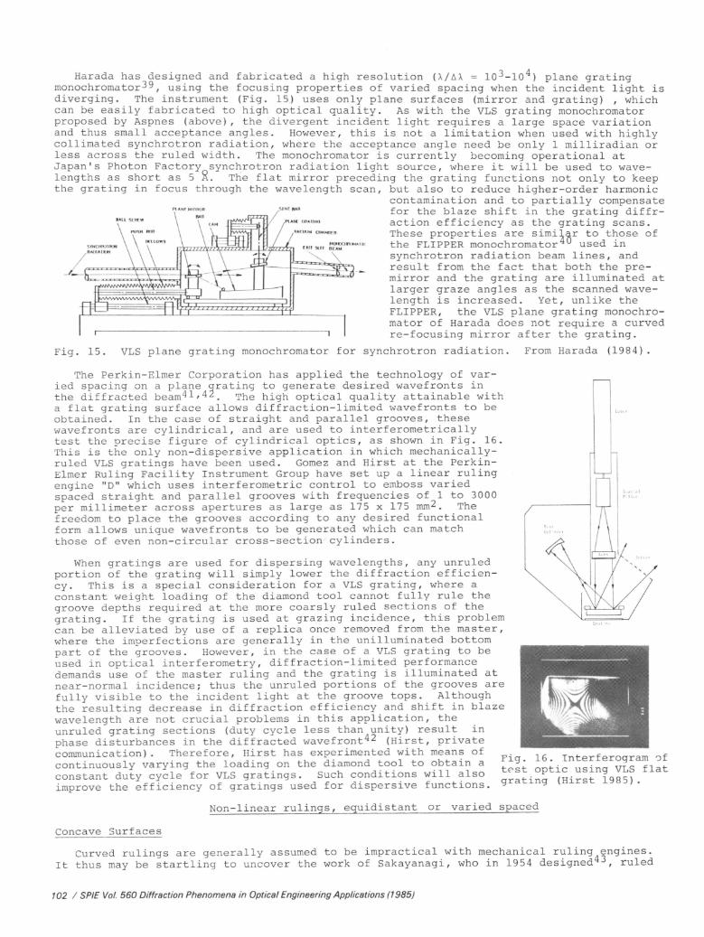
The Perkin -Elmer Corporation has applied the technology of var-ied spacing on a plane grating to generate desired wavefronts inthe diffracted beam41,42. The high optical quality attainable witha flat grating surface allows diffraction -limited wavefronts to beobtained. In the case of straight and parallel grooves, thesewavefronts are cylindrical, and are used to interferometricallytest the precise figure of cylindrical optics, as shown in Fig. 16.This is the only non- dispersive application in which mechanically -ruled VLS gratings have been used. Gomez and Hirst at the Perkin -Elmer Ruling Facility Instrument Group have set up a linear rulingengine "D" which uses interferometric control to emboss variedspaced straight and parallel grooves with frequencies of 1 to 3000per millimeter across apertures as large as 175 x 175 mm2. Thefreedom to place the grooves according to any desired functionalform allows unique wavefronts to be generated which can matchthose of even non -circular cross -section cylinders.
When gratings are used for dispersing wavelengths, any unruledportion of the grating will simply lower the diffraction efficien-cy. This is a special consideration for a VLS grating, where aconstant weight loading of the diamond tool cannot fully rule thegroove depths required at the more coarsly ruled sections of thegrating. If the grating is used at grazing incidence, this problemcan be alleviated by use of a replica once removed from the master,where the imperfections are generally in the unilluminated bottompart of the grooves. However, in the case of a VLS grating to beused in optical interferometry, diffraction -limited performancedemands use of the master ruling and the grating is illuminated atnear -normal incidence; thus the unruled portions of the grooves arefully visible to the incident light at the groove tops. Althoughthe resulting decrease in diffraction efficiency and shift in blazewavelength are not crucial problems in this application, theunruled grating sections (duty cycle less than unity) result in
phase disturbances in the diffracted wavefront42 (Hirst, privatecommunication). Therefore, Hirst has experimented with means ofcontinuously varying the loading on the diamond tool to obtain a
Fig. 16. Interferogram of
constant duty cycle for VLS gratings. Such conditions will also test optic using VLS flat
improve the efficiency of gratings used for dispersive functions,grating (Hirst 1985)
Non -linear rulings, equidistant or varied spaced
Concave Surfaces
Curved rulings are generally assumed to be impractical with mechanical ruling engines.It thus may be startling to uncover the work of Sakayanagi, who in 1954 designed43, ruled
102 / SPIE Vol. 560 Diffraction Phenomena in Optical Engineering Applications (1985)
Harada has designed and fabricated a high resolution (X/AX = 10 3 -1Q ) plane grating monochromator39 , using the focusing properties of varied spacing when the incident light is diverging. The instrument (Fig. 15) uses only plane surfaces (mirror and grating) , which can be easily fabricated to high optical quality. As with the VLS grating monochromator proposed by Aspnes (above), the divergent incident light requires a large space variation and thus small acceptance angles. However, this is not a limitation when used with highly collimated synchrotron radiation, where the acceptance angle need be only 1 milliradian or less across the ruled width. The monochromator is currently becoming operational at Japan's Photon Factory synchrotron radiation light source, where it will be used to wave lengths as short as 5 A. The flat mirror preceding the grating functions not only to keep the grating in focus through the wavelength scan, but also to reduce higher-order harmonic
contamination and to partially compensate for the blaze shift in the grating diffr action efficiency as the grating scans. These properties are similar to those of the FLIPPER monochromator 40 used in synchrotron radiation beam, lines, and result from the fact that both the pre- mirror and the grating are illuminated at larger graze angles as the scanned wave length is increased. Yet, unlike the FLIPPER, the VLS plane grating monochro mator of Harada does not require a curved re-focusing mirror after the grating.
Fig. 15. VLS plane grating monochromator for synchrotron radiation. From Harada (1984).
The Perkin-Elmer Corporation has applied the technology of var ied spacing on a plane grating to generate desired wavefronts in the diffracted beam4 '-'-' 4 '2 . The high optical quality attainable with a flat grating surface allows diffraction-limited wavefronts to' be obtained. In the case of straight and parallel grooves, these wavefronts are cylindrical, and are used to interferometrically test the precise figure of cylindrical optics, as shown in Fig. 16. This is the only non-dispersive application in which mechanically- ruled VLS gratings have been used. Gomez and Hirst at the Perkin- Elmer Ruling Facility Instrument Group have set up a linear ruling engine "D" which uses interferometrie control to emboss varied spaced straight and parallel grooves with frequencies of^l to 3000 pe r m i11imete r ac ros s ap e r tures a s large a s 175 x 175 mm. 2 . The freedom to place the grooves according to any desired functional form allows unique wavefronts to be generated which can match those of even non-circular cross-section cylinders.
When gratings are used for dispersing wavelengths, any unruled portion of the grating will simply lower the diffraction efficien cy. This is a special consideration for a VLS grating, where aconstant weight loading of the diamond tool cannot fully rule the groove depths required at the more coarsly ruled sections of the gr a t i ng. If the g ra t i ng is u s ed at grazing i nc ide nce, thi s p rob1em can be a 1 lev! a t e d by u s e of a r e p 1 i c a on c e r emo v e d. f r om t h e ma s t e r , where the imperfections are generally in the unilluminated bottom part of the grooves. However, in the case of a VLS grating to be used in optical interferometry, diffraction-limited performance demands use of the master ruling and the grating is illuminated at near-normal incidence; thus the unruled portions of the grooves are fully visible to the incident light at the groove tops. Although the resulting decrease in diffraction efficiency and shift in blaze wavelength are not crucial problems in this application, the unruled grating sections (duty cycle less than unity) result in phase disturbances in the diffracted wavefront42 (Hirst, private communication). Therefore, Hirst has experimented with means of continuously varying the loading on the diamond tool to obtain a constant duty cycle for VLS gratings. Such conditions will also improve the efficiency of gratings used for dispersive functions.
Fig. 16. In te r fer og r am o f test optic using VLS flat
Non-linear rulings, equidistant or varied spaced
Concave Surfaces
Curved rulings are generally assumed to be impractical with mechanical ruling engines. It thus may be startling to uncover the work of Sakayanagi, who in 1954 designed43 , ruled
102 / SPIE Vol. 560 Diffraction Phenomena in Optical Engineering Applications (1985)

and tested44 a curved groove grating. Sakayanagi's "curvedgrating" design principle is shown in Fig. 17. The gratingsurface is a sphere with radius R and center of curvature atpoint O. If projected onto the plane O'G tangent to the gra-ting, the grooves are circular with center at 0'. The threedimensional groove is a circle with symmetry axis 0'O on whichastigmatism must vanish provided the image and source both lieon this line. This sagittal focal curve of the grating inter-sects the meridional focal curve (Rowland circle) at twopoints. If the source and image are located at these twopoints, in addition to no astigmatism, the image will be infocus spectrally and contain no coma aberration. At normalincidence (within 30° of the grating normal) Sakayanagishowed there will be a useful range in wavelength where theastigmatism remains small.Subsequent theoretical workl2,45,46,particularly that of Strezhnev and Shmidt4' (and referencescited therein) revealed that a curved groove spherical gratingexhibits a broader region of astigmatism correction than would
Fig. 17. Sakayanagi curved grating (1954).
result from varied spacing alone or by use ofaspherical (e.g. toroidal) surfaces. In thecase of Sakayanagi's curved grating, thesagittal focal surface is altered, while theuniform spacings keep the meridional focalsurface intact.
Sakayangi's ruling apparatus is shown inFig. 18. This geometry constains the diamondD to move along a spherical surface with centerO' and radius p . (As discussed above, Haradahas more recently realized this curved grooveconstraint with a linear ruling motion by Fig. 18. Apparatus used by Sakayanagi totilting the reciprocation plane to coincide rule grooves of equal curvature on a sphere.with axis GS in Fig. 17. However, Sakayanagi'sfabrication method provided a curved ruling motion even if the grating surface was flat.) Aspherical grating blank of radius R =150 cm was used, and grooves of equal (not concentric)curvature p =315 cm were ruled with spacing 576 g /mm. The grating was illuminated with a Hglamp and the spectra obtained (Fig. 19) compared to a conventional concave grating.Although the spectra suffered from a large amount of stray light, this work demonstratedclearly that astigmatism could be eliminated using curved grooves.
Murty48 has proposed a spherical zone -plate diffractiongrating in reflection or transmission (Fig. 20). The gratingis aplanatic due to the choice of a coma -free surface PC (thecircle of Apollonius) along which the magnification betweenobject A and image A' is constant. Varied spacing is thenrequired to remove spherical aberration. For example, if theobject is at infinity, the grating surface is a sphere withcenter at the image. A mirror surface, of course, would havetwice this radius of curvature; thus the groove densities onthe grating must be quite high to remove spherical aberration,comparable to what is required for a planar zone plate. Murtyshowed that the grooves are at the intersection of parallelplanes spaced equally in the horizontal direction of Fig. 20.Thus, if viewed from the grating normal, the grooves are con-
centric with spacings whichvary inverse with theirradii. Murty recently hasproposed a tandem arrange-ment of two such gratingsto conruct a narrow -bandfilter. 9" While such gratingscould be fabricated by holo-graphic techniques, a mecha-nical ruling would providemuch larger apertures andmore easily attain the highgroove densities desired.
Fig. 20. Aplanatic spherical zoneplate diagram (Murty 1960).
(a)ao=-zas°a =-2GS°
cl
cal-25.5°
a = -2z°
5770L791 5a6i
/3=2° Z.
5
AsHgmolism 3°ero
-2°
Asrigmonsm zero
Fig. 19. Mercury spectrausing 1 mm long entranceslit. (a) curved grating,(b) conventional grating.From Sakayanagi (1954).
SP /E Vol 560 Diffraction Phenomena in Optical Engineering Applications (1985) / 103
and tested44 a curved groove grating. Sakayanagi's "curved grating" design principle is shown in Fig. 17. The grating surface is a sphere with radius R and center of curvature at point 0. If projected onto the plane O'G tangent to the gra ting, the grooves are circular with center at 0'. The three dimensional groove is a circle with symmetry axis O'O on which astigmatism must vanish provided the image and source both lie on this line. This sagittal focal curve of the grating inter sects the meridional focal curve (Rowland circle) at two points. If the source and image are located at these two points, in addition to no astigmatism, the image will be in focus spectrally and contain no coma aberration. At normal incidence (within 30° of the grating normal) Sakayanagi showed there will be a useful ranqe in wavelenqth where the astigmatism remains small. Subsequent theoretical work-^-^' ' , particularly that of Strezhnev and Shmidt 4 ' (and references cited therein) revealed that a curved groove spherical grating exhibits a broader region of astigmatism correction than would
Fig. 17. Sakayanagi curved grating (1954)..
result from varied spacing alone or by use of aspherical (e.g. toroidal) surfaces. In the case of Sakayanagi's curved grating, the sagittal focal surface is altered, while the uniform spacings keep the meridional focal surface intact.
Sakayangi's ruling apparatus is shown in Fig. 18. This geometry constains the diamond D to move along a spherical surface with center O 1 and radius p . (As discussed above, Harada has more recent?y realized this curved groove constraint with a linear ruling motion by tilting the reciprocation plane to coincide with axis GS in Fig. 17. However, Sakayanagi's fabrication method provided a curved ruling motion even if the grating surface was flat.) A spherical grating blank of radius R=150 cm was used, and grooves of equal (not concentric) curvature p=315 cm were ruled with spacing 576 g/mm. The grating was illuminated with a Hg lamp and the spectra obtained (Fig. 19) compared to a conventional concave grating. Although the spectra suffered from a large amount of stray light, this work demonstrated clearly that astigmatism could be eliminated using curved grooves.
Murty 48 has proposed a spherical zone-plate diffractiongrating in reflection or transmission (Fig. 20). The gratingis aplanatic due to the choice of a coma-free surface PC (thecircle of Apollonius) along which the magnification betweenobject A and image A 1 is constant. Varied spacing is thenrequired to remove spherical aberration. For example, if theobject is at infinity, the grating surface is a sphere withcenter at the image. A mirror surface, of course, would havetwice this radius of curvature; thus the groove densities onthe grating must be quite high to remove spherical aberration,comparable to what is required for a planar zone plate. Murtyshowed that the grooves are at the intersection of parallelplanes spaced equally in the horizontal direction of Fig. 20.Thus, if viewed from the grating normal, the grooves are con
centric with spacings which vary inverse with their radii. Murty recently has proposed a tandem arrange ment of two such gratings to construct a narrow-band filter. While such gratings could be fabricated by holo graphic techniques, a mecha nical ruling would provide much larger apertures and
Fig. 18. Apparatus used by Sakayanagi to rule grooves of equal curvature on a sphere.
Fig. 20. Aplanatic spherical zone plate diagram (Murty 1960) .
more easily attain the high groove densities desired.
Fig. 19. Mercury spectra using 1 mm long entrance slit. (a) curved grating, (b) conventional grating. From Sakayanagi (1954).
SPIE Vol. 560 Diffraction Phenomena in Optical Engineering Applications (1985) / 103

Plane Surfaces
Encouraged by the prospect of mechanically -ruled curved grooves, a number of authors haveproposed designs using plane grating surfaces and concentric grooves. Applications haveranged from use as fine -pitched rulers in surface metrology50 to spectroscopy at grazingincidence35,36,51 to interferometry at visible52 or at grazing incidence in the extreme UVor soft x- ray53. However, until recently such gratings have not been attempted with amechanical ruling eng4_ne, In 1982, the Perkin -Elmer Corporation constructed a prototyperotary ruling engine for ruling single -start concentric grooves with varied spacings.As with their linear varied -spaced gratings, the concentric gratings have been used togenerate desired wavefronts for the interferometric testing of curved surfaces - in thiscase spheres or aspheres. The grating behaves as a zone plate in reflection, focusing to apoint image either incident parallel light (in first order diffraction) or a point source(second order diffraction). One such "paraboloid- sphere" is shown in Fig. 21, for which thefocal length is 600 mm, corresponding to a groove density variation of approximately 50 -150g;mm for groove radii from approximately 20 to 60 mm. This grating has been used as a wave -front generator in interferometers to test spherical optics. Most recently, Hirst atPerkin -Elmer has, in addition to the prototype rotary engine, constructed an AdvancedCircular Ruling Engine which is capable of providing VLS groove densities up to 1500 g /mmon ruled diameters as large as 500 mm (these proceedings42). A photograph of this newruling engine is shown in Fig. 22.
Cr
1111111111111.Fig. 21. Concentric groove VLS plane grating:"Paraboloid- sphere ". Courtesy of G. Hirst,Perkin -Elmer Ruling Facility Instrument Group.
Fig. 22. Perkin -Elmer Advanced CircularRuling Engine. Courtesy of G. Hirst,Perkin -Elmer Ruling Facility.
Hettrick has proposed a concentric groove plane VLS grating design which removesastigmatism at all wavelengths at grazing incidence, and thus provides an ideal means oflow- dispersion order separation in a new echelle spectrometer51. One design variation ofsuch a grazing incidence system is shown in Fig. 23, where the high- dispersion echellegrating is also a VLS grating (which will be discussed in the next section). A high- resolu-tion spectrometer of this type, with the minimum number of reflections, was motivated by use
in future astronomical missions. The focal length of the concentric groove grating insuch applications is of order2 meters, requiring largeradii of the concentricgrooves. In anticipation ofspectroscopic use of con-centric grooves, B.W. Bach54at Hyperfine Inc. has recent-ly fabricated a grating withgroove radii from 400 mm to440 mm and, for initial testpurposes, with a constantgroove density of 600 g /mm.It should be noted that foruse at grazing incidence,only a small sector of agroove circle is used tocollect the incident light,unlike the situation forzone-plate normal incidence
NCIDENT FOCUS
applications as described Fig. 23. VLS grazing incidence echelle spectrometer, using a
above. concentric groove grating and fan grating (Hettrick 1985).
ECNELLE SPECTRUM
RULING FOCUS
TELESCOPEFAN ECNELLE
CONCENTRIC GROOVECROSS - DISPERSER
GROOVE
SYMMETRYAXIS
104 / SPIE ''Vol. 560 Diffraction Phenomena in Optical Engineering Applications (1985)
Plane Surfaces
Encouraged by the prospect of mechanically-ruled curved grooves, a number of authors have proposed designs using plane grating surfaces and concentric grooves. Applications have ranged from use as fine-pitched rulers in surface metrology 50 to spectroscopy at grazing incidence 35 /36,51 ^o interferometry at visible 52 or at grazing incidence in the extreme UV or soft x-ray 5 . However, until recently such gratings have not been attempted with a mechanical ruling engine. In 1982, the Perkin-Elmer Corporation constructed a prototype rotary ruling engine^ '^ for ruling single-start concentric grooves with varied spacings. As with their linear varied-spaced gratings, the concentric gratings have been used to generate desired wavefronts for the interferometric testing of curved surfaces - in this case spheres or aspheres. The grating behaves as a zone plate in reflection, focusing to a point image either incident parallel light (in first order diffraction) or a point source (second order diffraction). One such "paraboloid-sphere" is shown in Fig. 21, for which the focal length is 600 mm, corresponding to a groove density variation of approximately 50-150 g/min for groove radii from approximately 20 to 60 mm. This grating has been used as a wave- front generator in interferometers to test spherical optics. Most recently, Hirst at Perkin-Elmer has, in addition to the prototype rotary engine, constructed an Advanced Circular Ruling Engine which is capable of providing VLS groove densities up to 1500 g/mm on ruled diameters as large as 500 mm (these proceedings 42 ). A photograph of this new ruling engine is shown in Fig. 22.
Fig. 21. Concentric groove VLS plane grating: "Paraboloid-sphere". Courtesy of G. Hirst, Perkin-Elmer Ruling Facility Instrument Group.
Fig. 22. Perkin-Elmer Advanced Circular Ruling Engine. Courtesy of G. Hirst, Perkin-Elmer Ruling Facility.
,54
ECHELLE SPECTRUM
RULING FOCUS
Hettrick has proposed a concentric groove plane VLS grating design which removes astigmatism at all wavelengths at grazing incidence, and thus provides an ideal means of low-dispersion order separation in a new echelle spectrometer 5 -1-. One design variation of such a grazing incidence system is shown in Fig. 23, where the high-dispersion echelle grating is also a VLS grating (which will be discussed in the next section). A high-resolu tion spectrometer of this type, with the minimum number of reflections, was motivated by use in future astronomical missions. The focal length of the concentric groove grating in such applications is of order 2 meters, requiring large radii of the concentric grooves. In anticipation of spectroscopic use of con centric grooves, B.W. Bach at Hyperfine Inc. has recent ly fabricated a grating with groove radii from 400 mm to 440 mm and, for initial test purposes, with a constant groove density of 600 g/mm. It should be noted that for use at grazing incidence, only a small sector of a groove circle is used to collect the incident light, unlike the situation for zone-plate normal incidence applications as described above.
GROOVE • SYMMETRY
AXIS
CONCENTRIC GROOVE CROSS -DISPERSER
INCIDENT FOCUS
Fig. 23. VLS qrazing incidence echelle spectrometer, using a concentric groove grating and fan grating (Hettrick 1985).
104 / SPIE Vol. 560 Diffraction Phenomena in Optical Engineering Applications (1985}

Non -parallel rulings
"Fan error ", or successive non -parallelism, of grooves has been considered for some timeto be one of the demons of ruling large gratings55. Uncontrolled fanning of grooves is, ofcourse, undesirable and will degrade the resolution of a conventional grating whose groovesare assumed by the instrument designer to be perfectly parallel and straight. However,there are instances in which a controlled fanning of grooves can result in improved designs.
Concave Surfaces
In 1969, Baumgardner12 briefly discussed a fan -type ruling pattern for the correction ofimage rotation from a concave grating when mounted for off -plane diffraction. This rulingpattern, where the grooves are straight but slanted towards the central ruling with variousslopes, was shown by Baumgardner to remove first -order cross terms in the aberrant light -path function, and thus remove image distortion.
Plane Surfaces
Hettrick has proposed a "fan grating" for use at grazing incidence in convergent light,being the off -plane version of the plane grating geometry previously described. The imag-ing properties of these gratings, both in -plane and off -plane, were presented in severalpapers35,26,51 by Hettrick. In the fan grating design (Fig. 24), the grooves converge to acommon "ruling focus" and the diffracted wavelengths lie along a cone. This is a varied -space grating with the variation being in the direction along the groove lengths. Thiscorrects for the linearly varying focal distance to the spectral image, which without thespace var ation would result in a large first -order cross term in the aberrant light -pathfunction30. With fan grooves which converge to a ruling focus located behind the focalplane (and the virtual focus) by a distance
ARF = Lo sinyo tanyo , (4)
Hettrick showed that this aberration is essentially cancelled at grazing incidence. In thisequation, L is the nominal focal distance and y the nominal graze angle. A single gratingcan therefore be used in -focus at any graze angle, provided the focal surface and incidentvirtual source lie on a circle (Fig. 23) of diameter L /cosy , which intersects the gratingcenter, the virtual source, the spectral image and the °ruling focus. By an additionalspace variation between the grooves, the next most significant aberration (meridional coma),can be removed, resulting in potentially high resolution at grazing incidence. However,due to the inherently low dispersion of an off -plane grating of a given groove density, highresolution in practice requires use of high spectral orders. This is feasible with the fangrating due to the absence of shadowing (thus high diffraction efficiency) at large blazeangles, and a unique by- product of the fan pattern being a nearly constant blaze wavelengthacross the grating aperture. Hettrick used these advantages of an echelle fan to design aclass of grazing echelle spectrometer (Fig. 23).
Cash has also proposed use of fan -type rulings inlow spectral order56. Adopting the nomenclaturecommon in the opto- electronics industry57 and inmetrological applications using this pattern10,Cash refers to this as the "radial groove grating."
A fan grating or "radial grating" was mechanic-ally ruled by B.W. Bach at Hyperfine Inc. andsubsequently tested in EUV and soft x -ray light byWindt58. The ruling of a fan groove pattern isextremely challenging, as the groove depth variescontinuously along each groove, requiring a meansof continuously varying the weight loading on adiamond tool. Combined with the requirement oflarge blaze angles to operate as an echelle in thedesired high spectral orders, and the accompanyingrequirement of a second space variation between thegrooves for high resolution, a spectroscopicallyuseful fan grating is perhaps the most difficultof the VLS grating designs to fabricate.
DISPERSIONCONES
CORRECTING .`MIRROR `-fir
RULINGFOCUS
ZERO ORDER
R
FOCAL PLANE '0MIRROR FOCUS
Fig. 24. Fan grating, mounted forconical diffraction at grazingincidence in a convergent beam. Figurefor this plane grating from Hettrickand Bowyer (1983).
The future
The above review has inspired some speculation regarding the future direction in whichVLS gratings may be headed. In addition to the plethora of proposed grating designs, afraction of which have actually been ruled at present, the recent construction of rulingengines dedicated to varied -space capability has provided a forward momentum to the art.
SPIE Vol 560 Diffraction Phenomena in Optical Engineering Applications (1985) / 105
Non-parallel rulings
"Fan error", or successive non-parallelism, of grooves has been considered for some time to be one of the demons of ruling large gratings-^ . Uncontrolled fanning of grooves is, of course, undesirable and will degrade the resolution of a conventional grating whose grooves are assumed by the instrument designer to be perfectly parallel and straight. However, there are instances in which a controlled fanning of grooves can result in improved designs.
Concave Surfaces
In 1969, Baumgardner12 briefly discussed a fan-type ruling pattern for the correction of image rotation from a concave grating when mounted for off-plane diffraction. This ruling pattern, where the grooves are straight but slanted towards the central ruling with various slopes, was shown by Baumgardner to remove first-order cross terms in the aberrant light- path function, and thus remove image distortion.
Plane Surfaces
Hettrick has proposed a "fan grating" for use at grazing incidence in convergent light, being the off-plane version of the plane grating geometry previously described. The imag ing properties of these gratings, both in-plane and off-plane, were presented in several papers 3 -}, 36 , 51 by Hettrick. In the fan grating design (Fig. 24), the grooves converge to a common "ruling focus" and the diffracted wavelengths lie along a cone. This is a varied- space grating with the variation being in the direction along the groove lengths. This corrects for the linearly varying focal distance to the spectral image, which without the space variation would result in a large first-order cross term in the aberrant light-path function-* . With fan grooves which converge to a ruling focus located behind the focal plane (and the virtual focus) by a distance
ARF = L siny tarw (4)
Hettrick showed that this aberration is essentially cancelled at grazing incidence. In this equation, L is the nominal focal distance and y the nominal graze angle. A single grating can therefore be used in-focus at any graze angle, provided the focal surface and incident virtual source lie on a circle (Fig. 23) of diameter L /COSYQ , which intersects the grating center, the virtual source, the spectral image and the°ruling focus. By an additional space variation between the grooves, the next most significant aberration (meridional coma), can be removed, resulting in potentially high resolution at grazing incidence. However, due to the inherently low dispersion of an off-plane grating of a given groove density, high resolution in practice requires use of high spectral orders. This is feasible with the fan grating due to the absence of shadowing (thus high diffraction efficiency) at large blaze angles, and a unique by-product of the fan pattern being a nearly constant blaze wavelength across the grating aperture. Hettrick used these advantages of an echelle fan to design a class of grazing echelle spectrometer (Fig. 23).
Cash has also proposed use of fan-type rulings in low spectral order^. Adopting the nomenclature common in the opto-electronics industry^ an(j j_ n metrological applications using this pattern 10 , Cash refers to this as the "radial groove grating."
A fan grating or "radial grating" was mechanic ally ruled by B.W. Bach at Hyperfine Inc. and subsequently tested in EUV and soft x-ray light by Windt^S. The ruling of a fan groove pattern is extremely challenging, as the groove depth varies continuously along each groove, requiring a means of continuously varying the weight loading on a diamond tool. Combined with the requirement of large blaze angles to operate as an echelle in the desired high spectral orders, and the accompanying requirement of a second space variation between the grooves for high resolution, a spectroscopically useful fan grating is perhaps the most difficult of the VLS grating designs to fabricate.
The future
RULING FOCUS
\MIRROR FOCUS
Fig. 24. Fan grating, mounted for conical diffraction at grazing incidence in a convergent beam. Figure for this plane grating from Hettrick and Bowyer (1983).
The above review has inspired some speculation regarding the future direction in which VLS gratings may be headed. In addition to the plethora of proposed grating designs, a fraction of which have actually been ruled at present, the recent construction of ruling engines dedicated to varied-space capability has provided a forward momentum to the art.
SPIE Vol. 560 Diffract/on Phenomena in Optical Engineering Applications (1985) / 105

The use of plane VLS gratings in converging or diverging light is a recently deomonstra-ted geometry, and as such it is likely to quickly find applications in a number of diversefields. Its advantages in being used for large area moderate resolution astronomicalspectrometers are currently being explored at shorter and shorter wavelengths59. Inlaboratory spectroscopy, such designs can be adapted to time -resolved streak camerasó0, pro-viding a powerful method of plasma diagnostics. It may also be realistic to expect thestigmatic properties of VLS plane gratings to be used in extending interferometry to thesoft x -ray region by use of grazing incidence. Interferometry at these energies will bemade feasible by the development of intense coherent synchrotron radiation61. Furthertheoretical and experimental work on the properties of gratings with varied spacingmay also permit even further simplification of dispersive systems, whereby all the opticalfunctions required are perforifed in a single "monolithic" element.
A VLS concave grating design of tantalizing potential is the reflection zone plate, forwhich both coma and spherical aberration are absent. Such a grating should exhibit anexceptionally wide field of view, making it ideal for use as a camera or de- magnifyingmicroprobe with loose alignment tolerances. Since such a grating is used at normalincidence, it would either be restricted to wavelengths longer than approximately 200 R, orrequire multi -layer coatings which reflect only an interference -limited bandpass. A multi -layered aplanatic zone plate would also have minimum achromatism, allowing its use in strongcontinuum light such as synchrotron radiation.
Varied spacing also permits higher resolution to be attained, particularly at grazingincidence. Applications to monochromator and spectrometer design are at an early stage,and likely to proceed with increased vigor given the increased availability of intensesoft x -ray and extreme UV radiation.
Acknowledgements
The author wishes to thank those researchers who kindly provided information, andsometimes even original drawings or photographs, regarding their work: T. Harada, G. Hirst,B. Bach, and M.V.R.K. Murty. This review would of course not have been possible without thepublished efforts of a large number of people, both past and present, who's foresightinspired the present work. I apologize for any misinterpretations of the reviewed works.
References
1. H.A. Rowland, "On Concave Gratings for Optical Purposes," Phil. Mag. Vol. 16, p. 197,1883
2. H.A. Rowland, "Gratings in Theory and Practice," Phil. Mag. Vol. 35, p. 397, 1893.3. T. Lyman, "False Spectra from the Rowland Concave Grating," Phys. Rev. Vol. 12, p. 1,
1901; An Explanation of the False Spectra from Diffraction Gratings," Phys. Rev. Vol. 16,p. 257, 1903.
4. M.A. Cornu, "Sur la diffraction proprietes focales des reseaux," C.R. Acad. Sci. Vol.80, p. 645, 1875 (Paris); "Etudies sur les reseaux diffringents. Anomalies focales,"C.R. Acad. Sci. Vol. 116, p. 1215, 1893 (Paris); "Sur diverses methodes relatives al'observation des proprietes appelees anomalies focales des reseaux diffringents,"C.R. Acad. Sci. Vol. 116, p. 1421, 1893 Paris); "Verifications numeriques relatives auxproprietes focales des reseaux diffringents plans," C.R. Acad. Sci. Vol. 117, p. 1032,1893 (Paris).
5. G.R. Harrison, "The Diffraction Grating - An Opinionated Appraisal," Appl. Opt.Vol. 12, p. 2039, 1973.
6. W. Werner, "X -ray efficiencies of blazed gratings in extreme off -plane mountings,"Appl. Opt. Vol. 16, p. 2078, 1977.
7. B.W. Bach, "Vacuum ultraviolet gratings," SPIE Proc. Vol. 240, p. 223, 1980.8. A. Labeyrie and J. Flamand, "Spectrographic Performance of Holographically Made
Diffraction Gratings," Opt. Comm. Vol. 1, p. 5, 1969.9. A.J. Caruso, G.H. Mount and B.E. Woodgate, "Absolute s- and p- plane polarization
efficiencies for high frequency holographic gratings in the VUV," Appl. Opt. Vol. 20,p. 1764, 1981.
10. M.C. Hutley, Diffraction Gratings, Academic Press 1.982.11. Y. Sakayanagi, "A Stigmatic Concave Grating with Varying Spacing," Sci. Light,
Vol. 16, p. 129, 1967.12. J.D. Baumgardner, Theory and Design of Unusual Concave Gratings, Univ. Rochester
Thesis 1969.13. F.M. Gerasimov, "Use of Diffraction Gratings for Controlling a Ruling Engine,"
Appl. Opt. Vol. 6, p. 1861, 1967.14. F.M. Gerasimov, E.A. Yakovlev, I.V. Peisakhason and B.K. Koshelev, "Concave
Diffraction Gratings with Variable Spacing," Opt. Spectrosc. Vol. 28, p. 423, 1970.15. L. Rosen, "Focusing Hologram Diffraction Grating," Rev. Sci. Instrum. Vol. 38,
p. 438, 1967.
106 / SPIE Vol. 560 Diffraction Phenomena in Optical Engineering Applications (1985)
The use of plane VLS gratings in converging or diverging light is a recently deomonstra- ted geometry, and as such it is likely to quickly find applications in a number of diverse fields. Its advantages in being used for large area moderate resolution astronomical spectrometers are currently being explored at shorter and shorter wavelengths 59 . In laboratory spectroscopy, such designs can be adapted to time-resolved streak cameras 60 , pro viding a powerful method of plasma diagnostics. It may also be realistic to expect the stigmatic properties of VLS plane gratings to be used in extending interferometry to the soft x-ray reqion by use of grazing incidence. Interferometry at these energies will be made feasible by the development of intense coherent synchrotron radiation61 . Further theoretical and experimental work on the properties of gratings with varied spacing may also permit even further simplification of dispersive systems, whereby all the optical functions required are performed in a single "monolithic" element.
A VLS concave grating design of tantalizing potential is the reflection zone plate, for which both coma and spherical aberration are absent. Such a grating should exhibit an exceptionally wide field of view, making it ideal for use as a camera or de-magnifying microprobe with loose alignment tolerances. Since such a grating is used at normal incidence, it would either be restricted to wavelengths longer than approximately 200 8, or require multi-layer coatings which reflect only an interference-limited bandpass. A multi- layered aplanatic zone plate would also have minimum achromatism, allowing its use in strong continuum light such as synchrotron radiation.
Varied spacing also permits higher resolution to be attained, particularly at grazing incidence. Applications to monochromator and spectrometer design are at an early stage, and likely to proceed with increased vigor given the increased availability of intense soft x-ray and extreme UV radiation.
Acknowledgements
The author wishes to thank those researchers who kindly provided information, and sometimes even original drawings or photographs, regarding their work: T. Harada, G. Hirst, B. Bach, and M.V.R.K. Murty. This review would of course not have been possible without the published efforts of a large number of people, both past and present, who's foresight inspired the present work. I apologize for any misinterpretations of the reviewed works.
References
1. H.A. Rowland, "On Concave Gratings for Optical Purposes," Phil. Mag. Vol. 16, p. 197, 1883.
2. H.A. Rowland, "Gratings in Theory and Practice," Phil. Mag. Vol. 35, p. 397, 1893.3. T. Lyman, "False Spectra from the Rowland Concave Grating," Phys. Rev. Vol. 12, p. 1,
1901; "An Explanation of the False Spectra from Diffraction Gratings," Phys. Rev. Vol. 16, p. 257, 1903.
4. M.A. Cornu, "Sur la diffraction proprietes focales des reseaux," C.R. Acad. Sci. Vol. 80, p. 645, 1875 (Paris);"Etudies sur les reseaux diffringents. Anomalies focales," C.R. Acad. Sci. Vol. 116, p. 1215, 1893 (Paris); "Sur diverses methodes relatives a l f observation des proprietes appelees anomalies focales des reseaux diffringents," C.R, Acad. Sci. Vol. 116, p. 1421, 1893 Paris); "Verifications numeriques relatives aux proprietes focales des reseaux diffringents plans," C.R. Acad. Sci. Vol. 117, p. 1032, 1893 (Paris).
5. G.R. Harrison, "The Diffraction Grating - An Opinionated Appraisal," Appl. Opt. Vol. 12, p. 2039, 1973.
6. W. Werner, "X-ray efficiencies of blazed gratings in extreme off-plane mountings," Appl. Opt. Vol. 16, p. 2078, 1977.
7. B.W. Bach, "Vacuum ultraviolet gratings," SPIE Proc. Vol. 240, p. 223, 1980.8. A. Labeyrie and J. Flamand, "Spectrographic Performance of Holographically Made
Diffraction Gratings," Opt. Comm. Vol. 1, p. 5, 1969.9. A.J. Caruso, G.H. Mount and B.E. Woodgate, "Absolute s- and p- plane polarization
efficiencies for high frequency holographic gratings in the VUV," Appl. Opt. Vol. 20, p. 1764, 1981.
10. M.C. Hutley, Diffraction Gratings, Academic Press L982.11. Y. Sakayanagi, "A Stigmatic Concave Grating with Varying Spacing," Sci. Light,
Vol. 16, p. 129, 1967.12. J.D. Baumgardner, Theory and Design of Unusual Concave Gratings, Univ. Rochester
Thesis 1969.13. F.M. Gerasimov, "Use of Diffraction Gratings for Controlling a Ruling Engine,"
Appl. Opt. Vol. 6, p. 1861, 1967.14. F.M. Gerasimov, E.A. Yakovlev, I.V. Peisakhason and B.K. Koshelev, "Concave
Diffraction Gratings with Variable Spacing," Opt. Spectrosc. Vol. 28, p. 423, 1970.15. L. Rosen, "Focusing Hologram Diffraction Grating," Rev. Sci. Instrum. Vol. 38,
p. 438, 1967.
106 / SPIE Vol. 560 Diffraction Phenomena in Optical Engineering Applications (1985)

16. J. -D. Bartoe, G.E. Brueckner, J.D. Purcell and R. Tousey, "Extreme ultravioletspectrograph ATM experiment S082B," Appl. Opt. Vol. 16, p. 879, 1977; or SPIE Proc. Vol. 44,p. 153, 1974.
17. T. Harada, S. Moriyama and T. Kita, "Mechanically ruled stigmatic concave gratings,"Jpn. J. Appl. Phys. Vol. 14 (suppl. 14 -1), p. 175, 1975.
18. T. Harada, S. Moriyama, T. Kita and Y. Kondo, "Development of numerical controlruling engine for stigmatic concave grating," J. Jpn. Soc. Precision Eng. Vol. 42, p. 888,1976.
19. T. Harada and T. Kita, "Mechanically ruled aberration -corrected concave gratings,"Appl. Opt. Vol. 19, p. 3987, 1980; or T. Kita and T. Harada, "Mechanically ruled aberration- -corrected concave grating for high resolution Seya Namioka monochromator,"J. Spectrosc. Soc. Jpn. (Bunko Kenku) Vol. 29, p. 256, 1980.
20. R. Iwanaga and T. Oshio, "Aberration reduced mechanically ruled grating for simplerotational mounting," J. Opt. Soc. Am. Vol. 69, p. 1538, 1979.
21. T. Kita et al., "Mechanically ruled aberration -corrected concave gratings fora flat -field grazing incidence spectrograph," Appl. Opt. Vol. 22, p. 512, 1983.
22. J. Edelstein et al, "Extreme UV measurements of a varied line -space HItachi reflect-ion grating: efficiency and scattering," Appl. Opt. Vol. 23, p. 3267, 1984; "erratum,"Appl. Opt. Vol. 24, p. 153, 1985.
23. N. Nakano et al, "Development of a flat -field grazing incidence XUV spectrometer andits applications in picosecond XUV spectroscopy," Appl. Opt. Vol. 23, p. 2386, 1984.
24. T. Kita and T. Harada, "Use of aberration -corrected concave gratings in opticalde- multiplexers," Appl. Opt. Vol. 22, p. 819, 1983.
25. D.E. Aspnes, "High- efficiency concave -garting monochromator with wavelength- independ-ent focusing characteristics," J. Opt. Soc. Am. Vol. 72, p. 1056, 1982.
26. G.S. Monk, "A Mounting for the Plane Grating," J. Opt. Soc. Am. Vol. 17, p. 358, 192827. A.H.C.P. Gillieson, J. Sci. Instrum Vol. 26, p. 335, 1949.28. R.B. Barnes and P.W. Collyer, U.S. Patent 2,995,973 (Aug. 15, 1961).29. M.V.R.K. Murty, Use of Convergent and Divergent Illumination with Plane Gratings,"
J. Opt. Soc. Am. Vol. 52, p. 768, 1962.30. E.W. Richards, A.R. Thomas and W. Weinstein, A.E.R.E c/r 2152, 2163 (Harwell,
England, 1957).31. G. Rosendahl, "Contributions to the optics of mirror and gratings with oblique
incidence," Ball Bros. Res. Rep. (April 20, 1959).32. D.J. Schroeder, "Scanning Spectrometer of the Gillieson Type," Appl. Opt. Vol. 5,
p. 545, 1966.33. J.T. Hall, "Focal Properties of a Plane Grating in a Convergent Beam," Appl. Opt.
Vol. 5, p. 1051, 1966.34. M. Seya, T. Namioka and T. Sai, "Theory of a Plane Grating Mounting Utilizing
Convergent Illumination," Sci. Light Vol. 16, p. 138, 1967.35. M.C. Hettrick and S. Bowyer, "Variable line -space gratings: new designs for use in
grazing incidence spectrometers," Appl. Opt. Vol. 22, p. 3921, 1983.36. M.C. Hettrick, "Aberrations of varied line -space grazing incidence gratings in
converging light beams," Appl. Opt. Vol. 23, p. 3221, 1984.37. M.C. Hettrick et al, "Extreme ultraviolet Explorer spectrometer," Appl. Opt. Vol. 24,
p. 1737, 1985.38. B. Gale, "The theory of variable spacing gratings," Opt. Act. Vol. 13, p. 41, 1966.39. T. Harada, M. Itou and T. Kita, "A grazing incidence monochromator with a varied -
space plane grating for synchrotron radiation," SPIE Proc. Vol. 503, p. 114, 1984.40. H. Dietrich and C. Kunz, "A Grazing Incidence Vacuum Ultraviolet Monochromator with
Fixed Exit Slit," Rev. Sci. Instrum. Vol. 43, p. 434, 1972.41. H.W. Marshall and G.E. Hirst, "Diffraction Gratings and Replication,"
Perkin -Elmer technote Vol. 2, p. 1, 1985.42. G.E. Hirst, "Some recent developments in the fabrication of variably- spaced linear
and circular diffraction gratings," SPIE Proc. (this volume, 1985).43. Y. Sakayanagi, "Theory of Grating with Circular Grooves (Curved grating),"
Sci. Light Vol. 3, p. 1, 1954.44. Y. Sakayanagi, "Ruling of a Curved Grating," Sci. Light Vol. 3, p. 79, 1955.45. M. Singh and K. Majumder, "Cylindrical Gratings with Circular Grooves," Sci. Light
Vol. 18, p. 57, 1969.46. I.V. Peisakhson and Yu.V. Bazhanov, "The aberrations of a concave grating with
curved rulings," Sov. J. Opt. Technol. Vol. 42, p. 579, 1975.47. S.A. Strezhnev and N.S. Shmidt, "Astigmatism of spherical concave gratings with
non -rectilinear rulings," Opt. Spectrosc. Vol. 39, p. 213, 1975.48. M.V.R.K. Murty, "Spherical zone -plate diffraction grating," J. Opt. Soc. Am.
Vol. 50, p. 923, 1960.49. M.V.R.K. Murty and N.C. Das, "Narrow -band filter consisting of two aplanatic
gratings," J. Opt. Soc. Am. Vol. 72, p. 1714, 1982.50. J. Dyson, "Circular and spiral diffraction gratings," Proc. Royal Soc. Vol. 248,
p. 93, 1958.51. M.C. Hettrick, "Grazing incidence echelle spectrometers using varied line -space
gratings," Appl. Opt. Vol. 24, p. 1251, 1985.
SPIE Vol 560 Diffraction Phenomena in Optical Engineering Applications (1985) / 107
16. J.-D. Bartoe, G.E. Brueckner, J.D. Purcell and R. Tousey, "Extreme ultraviolet spectrograph ATM experiment S082B," Appl. Opt. Vol. 16, p. 879, 1977; or SPIE Proc. Vol. 44, p. 153, 1974.
17. T. Harada, S. Moriyama and T. Kita, "Mechanically ruled stigmatic concave gratings," Jpn. J. Appl. Phys. Vol. 14 (suppl. 14-1), p. 175, 1975.
18. T. Harada, S. Moriyama, T. Kita and Y. Kondo, "Development of numerical control ruling engine for stigmatic concave grating," J. Jpn. Soc. Precision Eng. Vol. 42, p. 888, 1976.
19. T. Harada and T. Kita, "Mechanically ruled aberration-corrected concave gratings," Appl. Opt. Vol. 19, p. 3987, 1980; or T. Kita and T. Harada, "Mechanically ruled aberration- corrected concave grating for high resolution Seya Namioka monochromator," J. Spectrosc. Soc. Jpn. (Bunko Kenku) Vol. 29, p. 256, 1980.
20. R. Iwanaga and T. Oshio, "Aberration reduced mechanically ruled grating for simple rotational mounting," J. Opt. Soc. Am. Vol. 69, p. 1538, 1979.
21. T. Kita et al., "Mechanically ruled aberration-corrected concave gratings for a flat-field grazing incidence spectrograph," Appl. Opt. Vol. 22, p. 512, 1983.
22. J. Edelstein et al, "Extreme UV measurements of a varied line-space Hitachi reflect ion grating: efficiency and scattering," Appl. Opt. Vol. 23, p. 3267, 1984; "erratum," Appl. Opt. Vol. 24, p. 153, 1985.
23. N. Nakano et al, "Development of a flat-field grazing incidence XUV spectrometer and its applications in picosecond XUV spectroscopy," Appl. Opt. Vol. 23, p. 2386, 1984.
24. T. Kita and T. Harada, "Use of aberration-corrected concave gratings in optical de-multiplexers," Appl. Opt. Vol. 22, p. 819, 1983.
25. D.E. Aspnes, "High-efficiency concave-garting monochromator with wavelength-independ ent focusing characteristics," J. Opt. Soc. Am. Vol. 72, p. 1056, 1982.
26. G.S. Monk, "A Mounting for the Plane Grating," J. Opt. Soc. Am. Vol. 17, p. 358, 192827. A.H.C.P. Gillieson, J. Sci. Instrum Vol. 26, p. 335, 1949.28. R.B. Barnes and P.W. Collyer, U.S. Patent 2,995,973 (Aug. 15, 1961).29. M.V.R.K. Murty, "Use of Convergent and Divergent Illumination with Plane Gratings,"
J. Opt. Soc. Am. Vol. 52, p. 768, 1962.30. E.W. Richards, A.R. Thomas and W. Weinstein, A.E.R.E c/r 2152, 2163 (Harwell,
England, 1957) .31. G. Rosendahl, "Contributions to the optics of mirror and gratings with oblique
incidence," Ball Bros. Res. Rep. (April 20, 1959).32. D.J. Schroeder, "Scanning Spectrometer of the Gillieson Type," Appl. Opt. Vol. 5,
p. 545, 1966.33. J.T. Hall, "Focal Properties of a Plane Grating in a Convergent Beam," Appl. Opt.
Vol. 5, p. 1051, 1966.34. M. Seya, T. Namioka and T. Sai, "Theory of a Plane Grating Mounting Utilizing
Convergent Illumination," Sci. Light Vol. 16, p. 138, 1967.35. M.C. Hettrick and S. Bowyer, "Variable line-space gratings: new designs for use in
grazing incidence spectrometers," Appl. Opt. Vol. 22, p. 3921, 1983.36. M.C. Hettrick, "Aberrations of varied line-space grazing incidence gratings in
converging light beams," Appl. Opt. Vol. 23, p. 3221, 1984.37. M.C. Hettrick et al, "Extreme ultraviolet Explorer spectrometer," Appl. Opt. Vol. 24,
p. 1737, 1985.38. B. Gale, "The theory of variable spacing gratings," Opt. Act. Vol. 13, p. 41, 1966.39. T. Harada, M. Itou and T. Kita, "A grazing incidence monochromator with a varied-
space plane grating for synchrotron radiation," SPIE Proc. Vol. 503, p. 114, 1984.40. H. Dietrich and C. Kunz, "A Grazing Incidence Vacuum Ultraviolet Monochromator with
Fixed Exit Slit," Rev. Sci. Instrum. Vol. 43, p. 434, 1972.41. H.W. Marshall and G.E. Hirst, "Diffraction Gratings and Replication,"
Perkin-Elmer technote Vol. 2, p. 1, 1985.42. G.E. Hirst, "Some recent developments in the fabrication of variably-spaced linear
and circular diffraction gratings," SPIE Proc. (this volume, 1985).43. Y. Sakayanagi, "Theory of Grating with Circular Grooves (Curved grating),"
Sci. Light Vol. 3, p. 1, 1954.44. Y. Sakayanagi, "Ruling of a Curved Grating," Sci. Light Vol. 3, p. 79, 1955.45. M. Singh and K. Majumder, "Cylindrical Gratings with Circular Grooves," Sci. Light
Vol. 18, p. 57, 1969.46. I.V. Peisakhson and Yu.V. Bazhanov, "The aberrations of a concave grating with
curved rulings," Sov. J. Opt. Technol. Vol. 42, p. 579, 1975.47. S.A. Strezhnev and N.S. Shmidt, "Astigmatism of spherical concave gratings with
non-rectilinear rulings," Opt. Spectrosc. Vol. 39, p. 213, 1975.48. M.V.R.K. Murty, "Spherical zone-plate diffraction grating," J. Opt. Soc. Am.
Vol. 50, p. 923, 1960.49. M.V.R.K. Murty and N.C. Das, "Narrow-band filter consisting of two aplanatic
gratings," J. Opt. Soc. Am. Vol. 72, p. 1714, 1982.50. J. Dyson, "Circular and spiral diffraction gratings," Proc. Royal Soc. Vol. 248,
p. 93, 1958.51. M.C. Hettrick, "Grazing incidence echelle spectrometers using varied line-space
gratings," Appl. Opt. Vol. 24, p. 1251, 1985.
SPIE Vol. 560 Diffraction Phenomena in Optical Engineering Applications (1985) / 107

52. K.M. Bystricky and T.A. Fritz, "Advanced Circularly Ruled Gratings for GeneralSurface Metrology," SPIE Proc. Vol. 429, p. 119, 1983.
53. M.C. Hettrick and C. Martin, "Interference Methods in the Testing and Fabrication ofNew -Design Grazing Incidence Gratings," SPIE Proc. Vol. 503, p. 106, 1984.
54. B.W. Bach, Hyperfine Incorporated, private communication (Aug. 1985).55. G.R. Harrison et al, "Ruling of LPrge Diffraction Gratings with Interfereometric
Control," J. Opt. Soc. Am. Vol. 47, p. 15, 1957.56. W. Cash, Jr., "X -Ray spectrographs using radial groove gratings," Appl. Opt. Vol. 22,
p. 3971, 1983.57. S. -L. Huang et al, "A HIgh- Accuracy Radial Grating Generating Machine with Opto-
Electric Control," Proc. Thirteenth Congress of International Commission for Optics, p. 560,1984 (Sapporo, Japan).
58. D.L. Windt and W. Cash, "Laboratory evaluation of conical diffraction spectrographs,"SPIE Proc. Vol. 503, p. 98, 1984.
59. S.M. Kahn and M.C. Hettrick, "The Application of Reflection Gratings to a Large AreaX -Ray Spectroscopy Mission: A Discussion of Scientific Requirements and Various DesignOptions," Proc. ESA Workshop on a Cosmic X -Ray Spectroscopy Mission (Lyngby, Denmark 1985).
60. G.L. Stradling, D.T. Attwood and R.L. Kauffman, "A Soft X -Ray Streak Camera,"IEEE J. Quantum Elect. Vol. 19, p. 604, 1983.
61. D. Attwood, K. Halbach and K. -Je Kim, "Tunable Coherent X- Rays," Science Vol. 228,p. 1265, 1985.
108 / SP/E Vol. 560 Diffraction Phenomena in Optical Engineering Applications (1985)
52. K.M. Bystricky and T.A. Fritz, "Advanced Circularly Ruled Gratings for General Surface Metrology," SPIE Proc. Vol. 429, p. 119, 1983.
53. M.C. Hettrick and C. Martin, "Interference Methods in the Testing and Fabrication of New-Design Grazing Incidence Gratings," SPIE Proc. Vol. 503, p. 106, 1984.
54. B.W. Bach, Hyperfine Incorporated, private communication (Aug. 1985).55. G.R. Harrison et al, "Ruling of Large Diffraction Gratings with Interfereometric
Control," J. Opt. Soc. Am. Vol . 47, p. 15, 1957.56. W. Cash, Jr., "X-Ray spectrographs using radial groove gratings," Appl. Opt. Vol. 22,
p. 3971, 1983.57. S.-L. Huang et al, "A High-Accuracy Radial Grating Generating Machine with Opto-
Electric Control," Proc. Thirteenth Congress of International Commission for Optics, p. 560, 1984 (Sapporo, Japan).
58. D.L. Windt and W. Cash, "Laboratory evaluation of conical diffraction spectrographs," SPIE Proc. Vol. 503, p. 98, 1984.
59. S.M. Kahn and M.C. Hettrick, "The Application of Reflection Gratings to a Large Area X-Ray Spectroscopy Mission: A Discussion of Scientific Requirements and Various Design Options," Proc. ESA Workshop on a Cosmic X-Ray Spectroscopy Mission (Lyngby, Denmark 1985).
60. G.L. Stradling, D.T. Attwood and R.L. Kauffman, "A Soft X-Ray Streak Camera," IEEE J. Quantum Elect. Vol. 19, p. 604, 1983.
61. D. Attwood, K. Halbach and K.-Je Kirn, "Tunable Coherent X-Rays," Science Vol. 228, p. 1265, 1985.
108 / SPIE Vol. 560 Diffraction Phenomena in Optical Engineering Applications (1985)