Embed Size (px)
Citation preview
Vasyl Kravchyk, EIT, PMP – NYC DEPMarc Santos, PE – Hazen and Sawyer
2
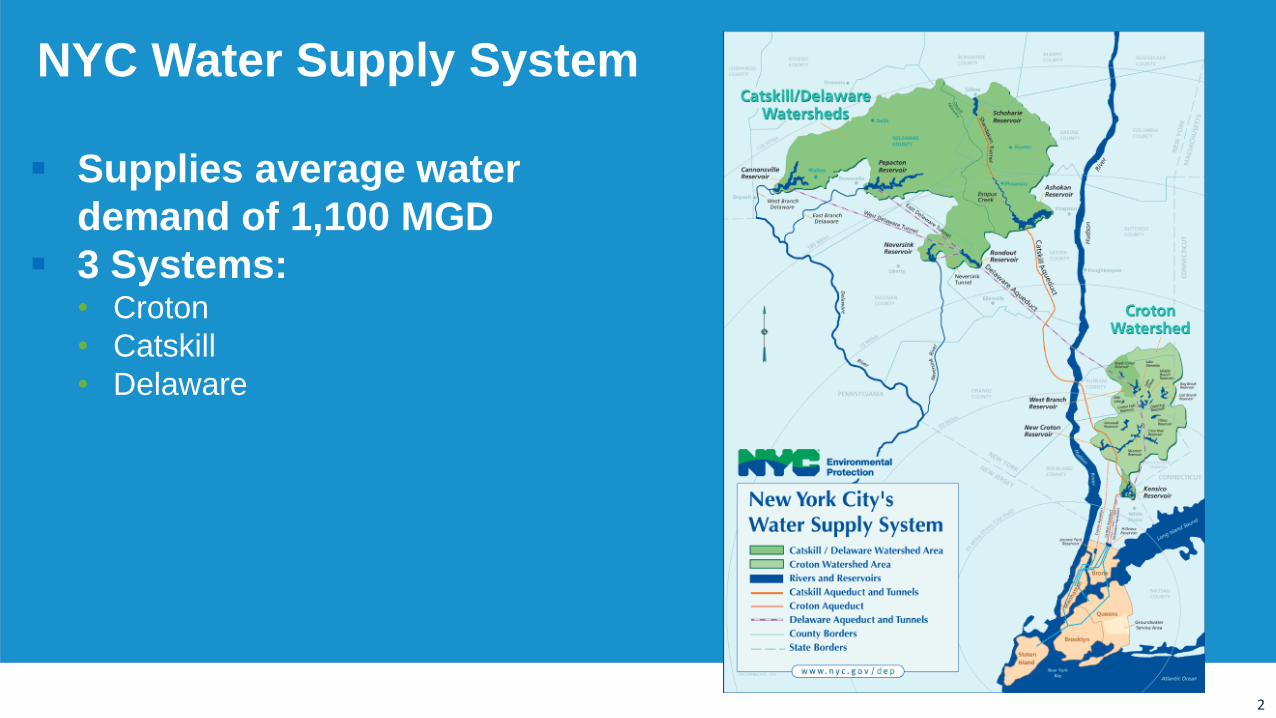
NYC Water Supply System
Supplies average water
demand of 1,100 MGD
3 Systems:• Croton
• Catskill
• Delaware
3
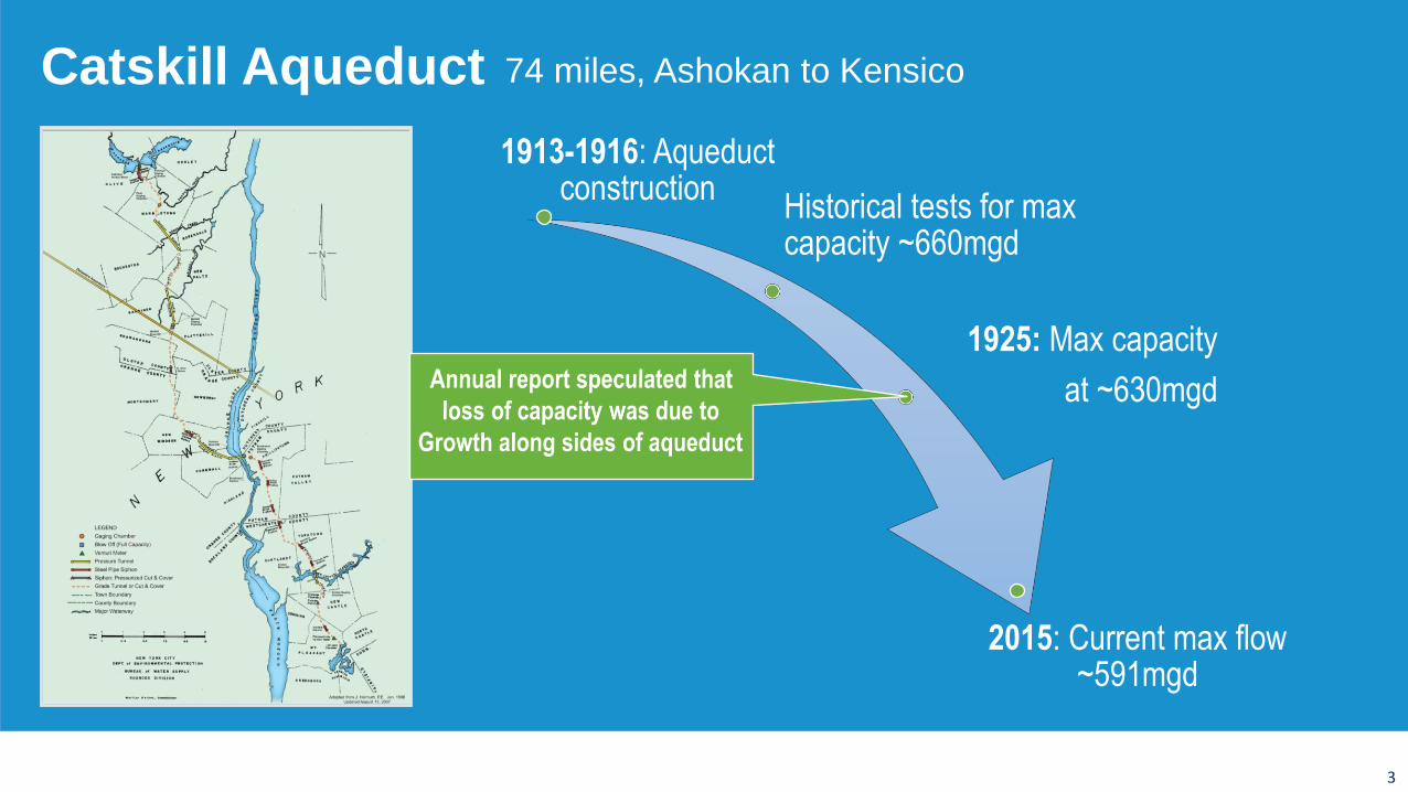
74 miles, Ashokan to KensicoCatskill Aqueduct
1913-1916: Aqueduct construction
Historical tests for max capacity ~660mgd
1925: Max capacity
at ~630mgd
2015: Current max flow ~591mgd
4
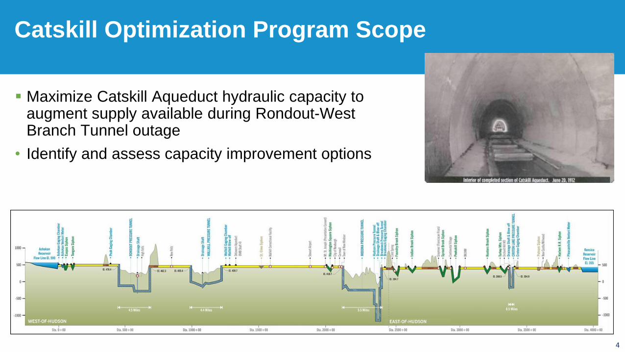
Maximize Catskill Aqueduct hydraulic capacity to augment supply available during Rondout-West Branch Tunnel outage
• Identify and assess capacity improvement options
Catskill Optimization Program Scope
5
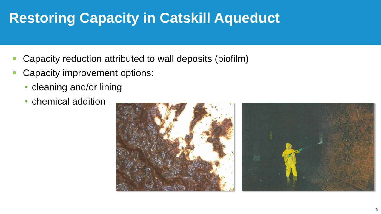
Restoring Capacity in Catskill Aqueduct
5
Capacity reduction attributed to wall deposits (biofilm)
Capacity improvement options:
• cleaning and/or lining
• chemical addition
6
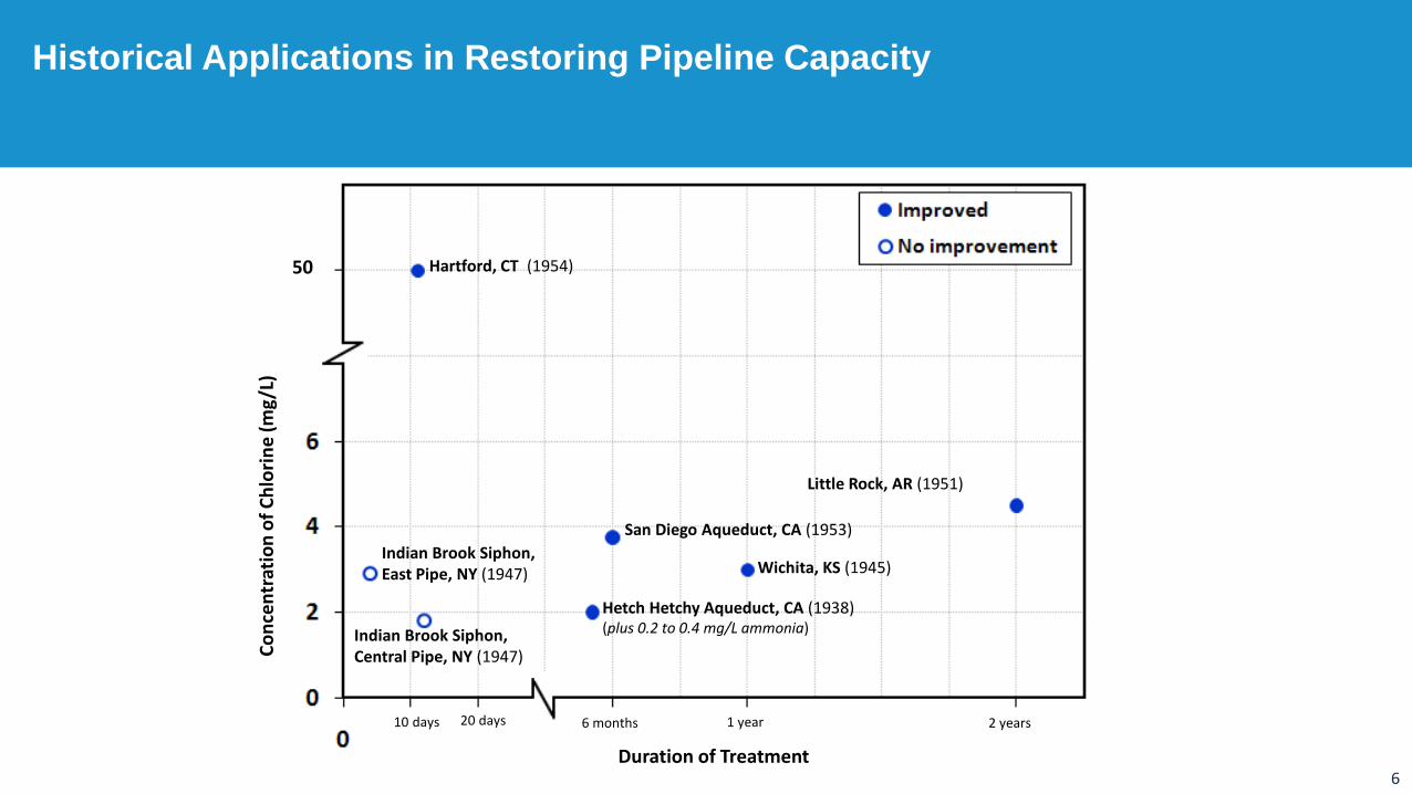
Historical Applications in Restoring Pipeline Capacity
50
10 days 20 days
Indian Brook Siphon, East Pipe, NY (1947)
Hartford, CT (1954)
San Diego Aqueduct, CA (1953)
Wichita, KS (1945)
Little Rock, AR (1951)
Indian Brook Siphon, Central Pipe, NY (1947)
Hetch Hetchy Aqueduct, CA (1938)(plus 0.2 to 0.4 mg/L ammonia)
Duration of Treatment
Co
nce
ntr
atio
n o
f C
hlo
rin
e (
mg/
L)
6 months 1 year 2 years
7
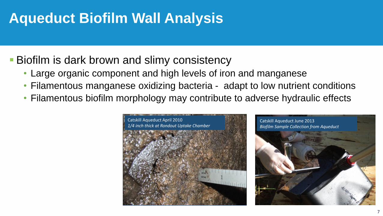
Biofilm is dark brown and slimy consistency• Large organic component and high levels of iron and manganese
• Filamentous manganese oxidizing bacteria - adapt to low nutrient conditions
• Filamentous biofilm morphology may contribute to adverse hydraulic effects
Aqueduct Biofilm Wall Analysis
Catskill Aqueduct April 20101/4 inch thick at Rondout Uptake Chamber
Catskill Aqueduct June 2013Biofilm Sample Collection from Aqueduct
8
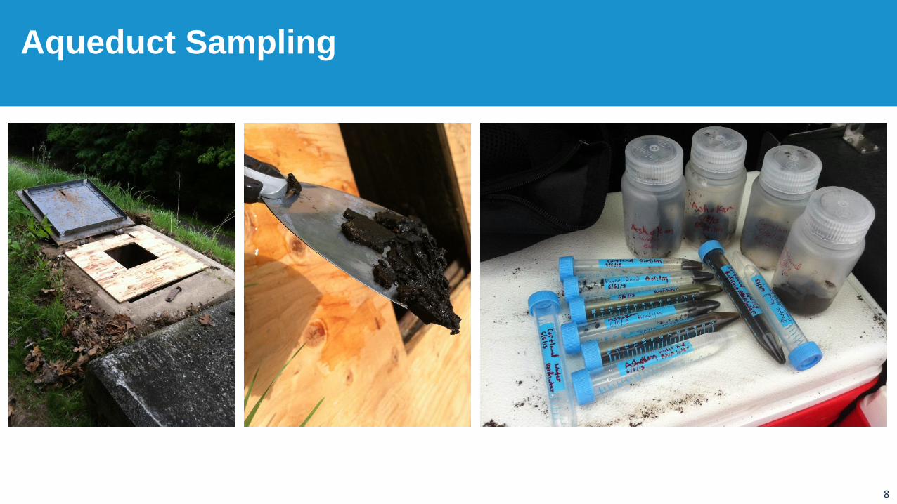
Aqueduct Sampling
9
Primary Objective (ATL Study)1. Hydraulic Benefit from chemical addition for:
a) Mitigation of new biofilm growth
b) Reduction of existing biofilm
c) Type of chemical
Secondary Objectives
2. Turbidity impacts of adding chemicals
3. Decay Rates of oxidants along the length of the aqueduct
4. DBP formation in varying seasons
Ashokan Test Loop Study Objectives
10
Phase I: Biofilm growth to establish population
Phase II: Chemical addition to Treat biofilm
• Raw Water (control)
• Sodium Hypochlorite
• Chloramines
• Chlorine Dioxide
Phase III: Chemical addition and dechlorination(investigate oxidation effects)
Primary Objective Test Plan
11
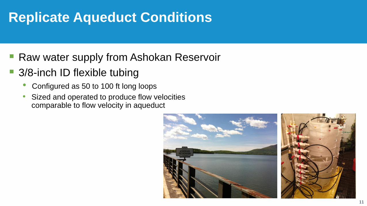
Raw water supply from Ashokan Reservoir
3/8-inch ID flexible tubing
• Configured as 50 to 100 ft long loops
• Sized and operated to produce flow velocities comparable to flow velocity in aqueduct
Replicate Aqueduct Conditions
12
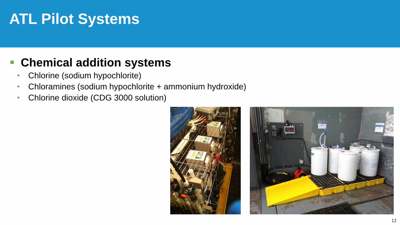
Chemical addition systems • Chlorine (sodium hypochlorite)
• Chloramines (sodium hypochlorite + ammonium hydroxide)
• Chlorine dioxide (CDG 3000 solution)
ATL Pilot Systems
13
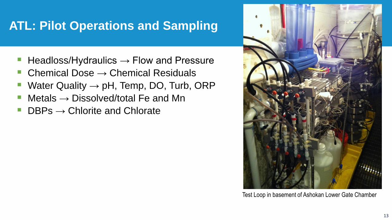
Headloss/Hydraulics → Flow and Pressure
Chemical Dose → Chemical Residuals
Water Quality → pH, Temp, DO, Turb, ORP
Metals → Dissolved/total Fe and Mn
DBPs → Chlorite and Chlorate
ATL: Pilot Operations and Sampling
Test Loop in basement of Ashokan Lower Gate Chamber
14
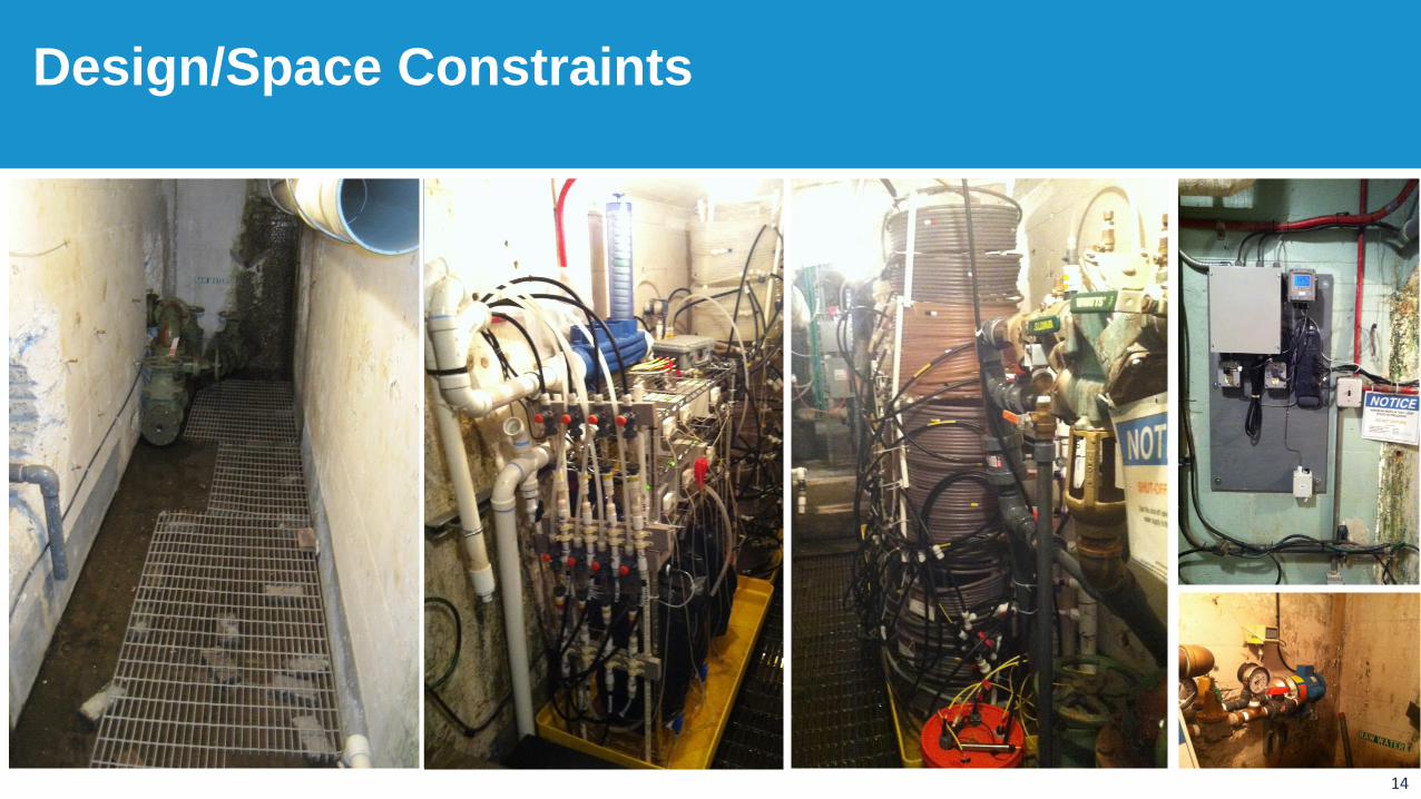
Design/Space Constraints
15
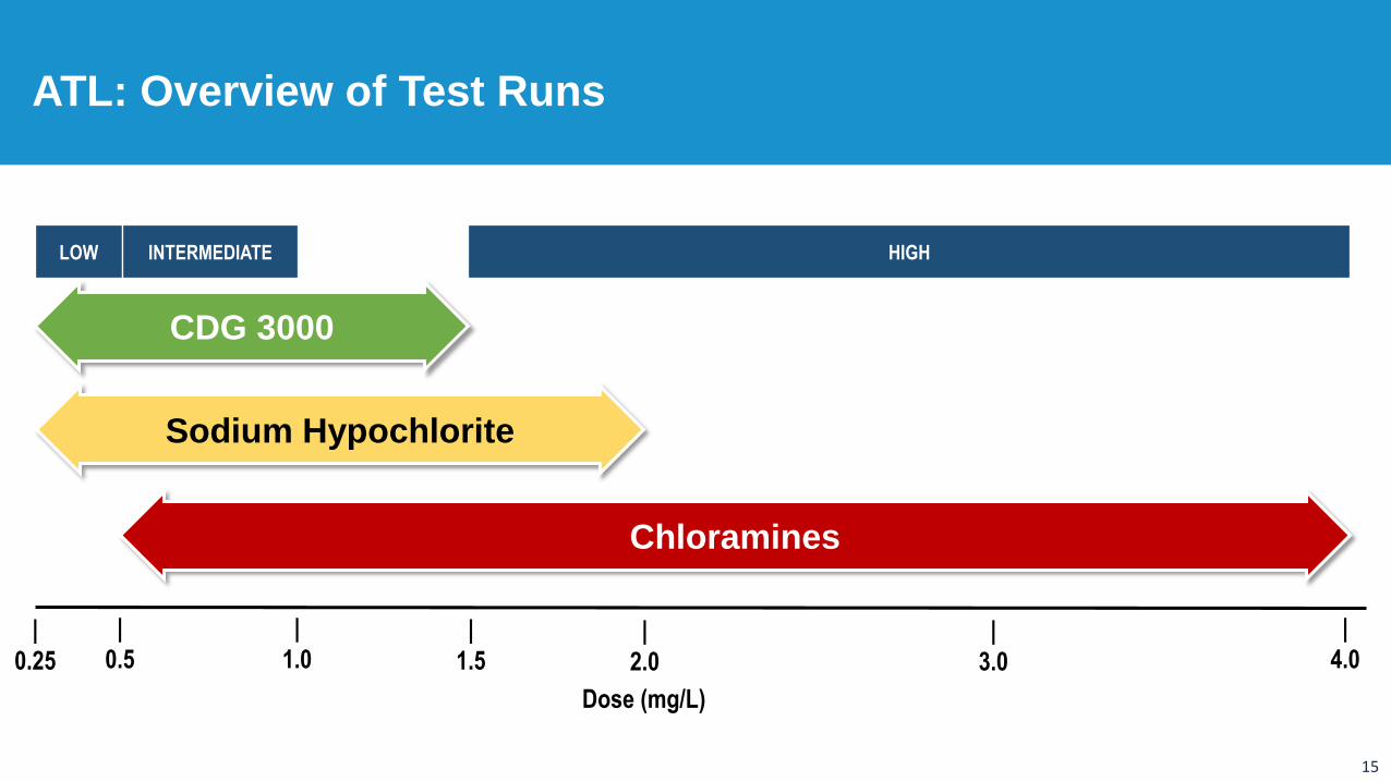
ATL: Overview of Test Runs
Dose (mg/L)
LOW INTERMEDIATE HIGH
|
0.25
|
0.5|
2.0
|
4.0
|
1.0|
1.5|
3.0
CDG 3000
Sodium Hypochlorite
Chloramines
16
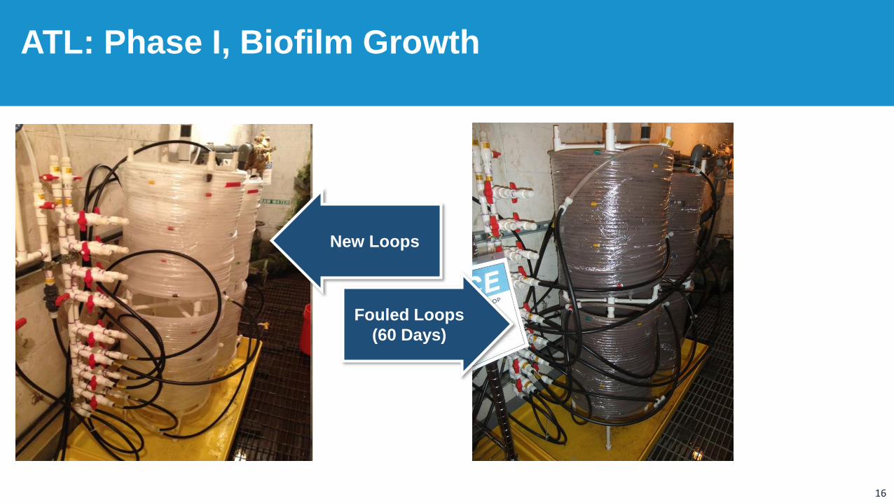
ATL: Phase I, Biofilm Growth
New Loops
Fouled Loops
(60 Days)
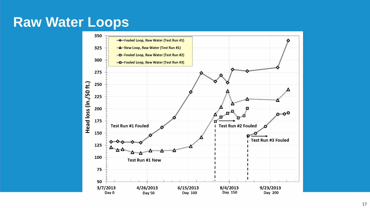
17
Raw Water Loops
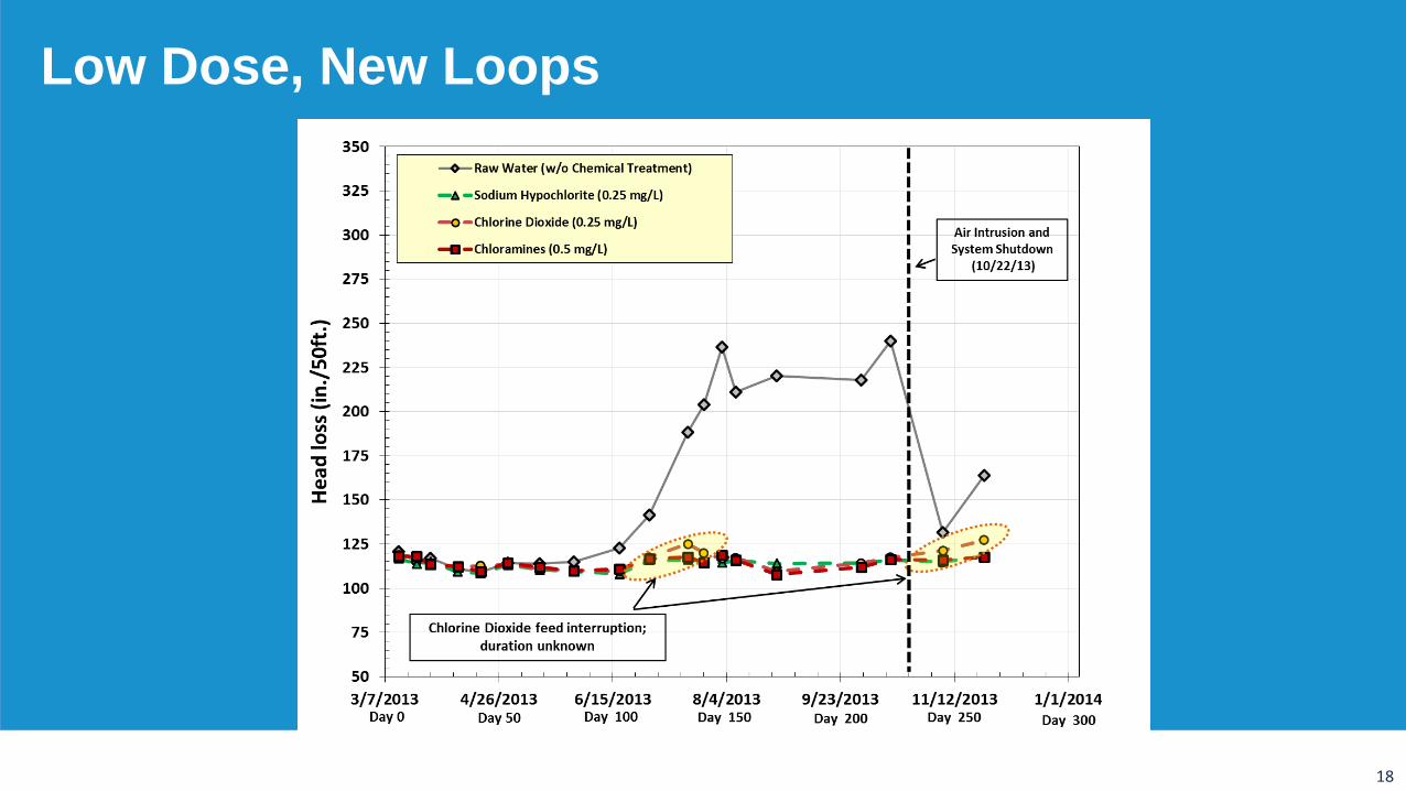
18
Low Dose, New Loops
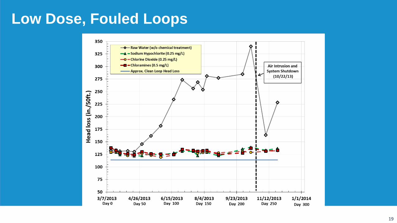
19
Low Dose, Fouled Loops
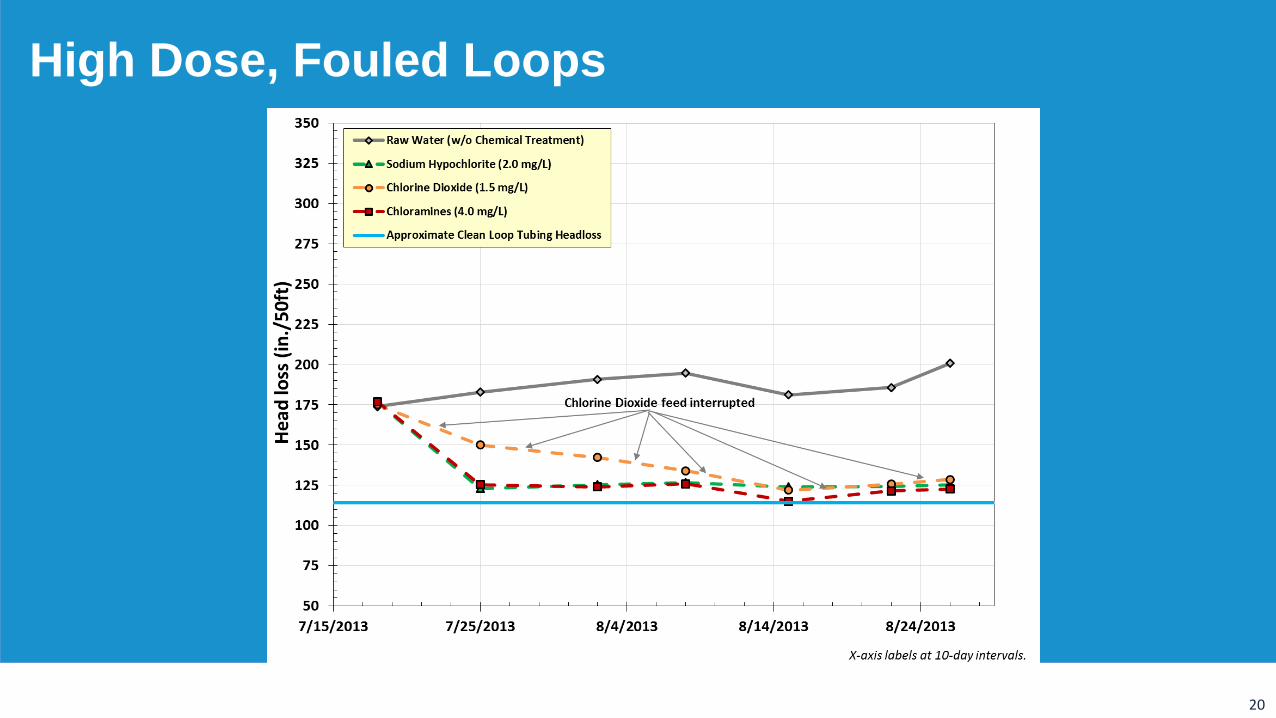
20
High Dose, Fouled Loops
21
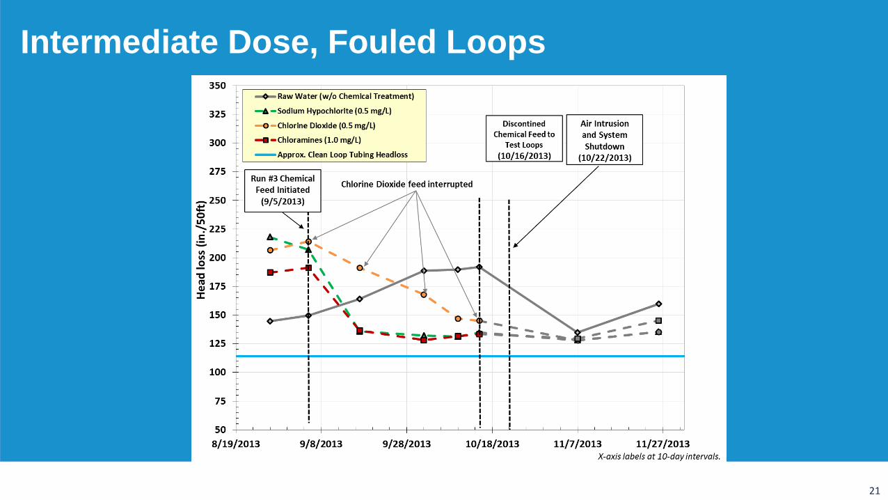
Intermediate Dose, Fouled Loops
22
Objective 1a: Prevention of new biofilm growth
• Low doses maintained hydraulic performance on new loops
Objective 1b: Reduction of headloss with established biofilm
• Low doses maintained hydraulic performance on fouled loops
• High and intermediate doses improved hydraulic performance of fouled loops
Objective 1c: Comparison of hydraulic benefit by oxidant
• Clear difference between hydraulic performance of raw water loops and treated chemical loops
• All chemicals provided equal treatment performance in test loops
• Chlorine dioxide performed equally to sodium hypochlorite and chloramines without a residual
Summary of Treatment Phases
23
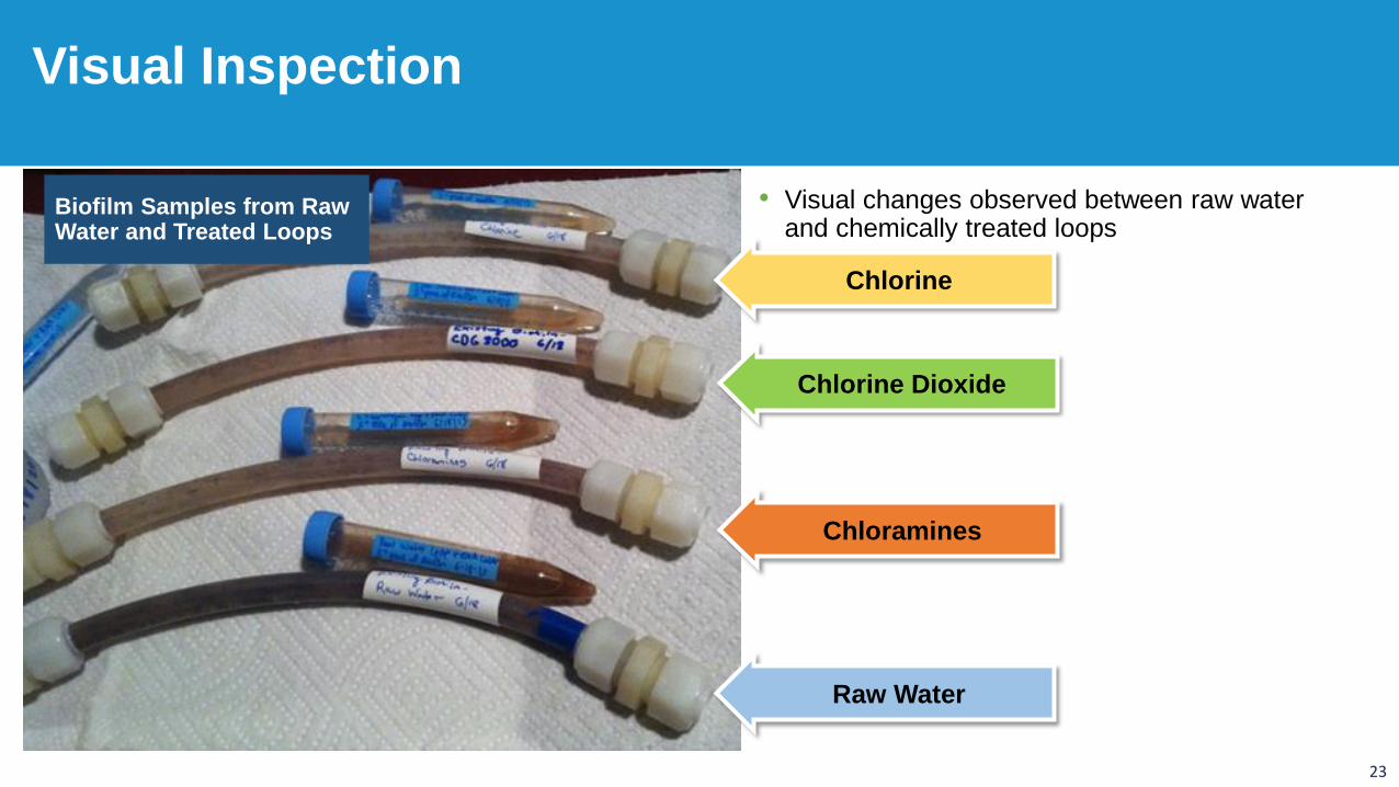
• Visual changes observed between raw water and chemically treated loops
Biofilm Samples from Raw Water and Treated Loops
Visual Inspection
Chlorine
Chlorine Dioxide
Chloramines
Raw Water
24
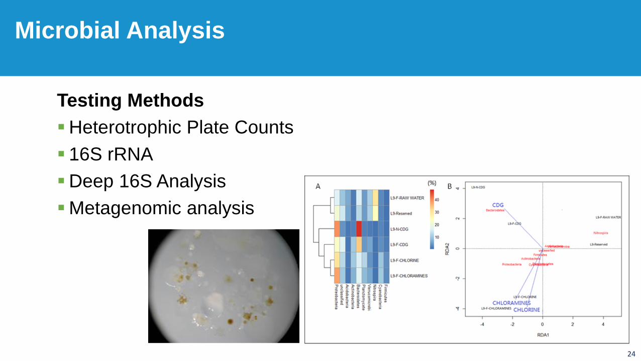
Testing Methods
Heterotrophic Plate Counts
16S rRNA
Deep 16S Analysis
Metagenomic analysis
Microbial Analysis
25
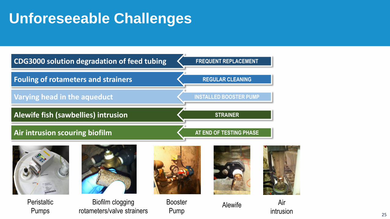
Unforeseeable Challenges
Air
intrusionAlewifeBiofilm clogging
rotameters/valve strainers
CDG3000 solution degradation of feed tubing FREQUENT REPLACEMENT
Fouling of rotameters and strainers REGULAR CLEANING
Varying head in the aqueduct INSTALLED BOOSTER PUMP
Alewife fish (sawbellies) intrusion STRAINER
Air intrusion scouring biofilm AT END OF TESTING PHASE
Booster
Pump
Peristaltic
Pumps
26
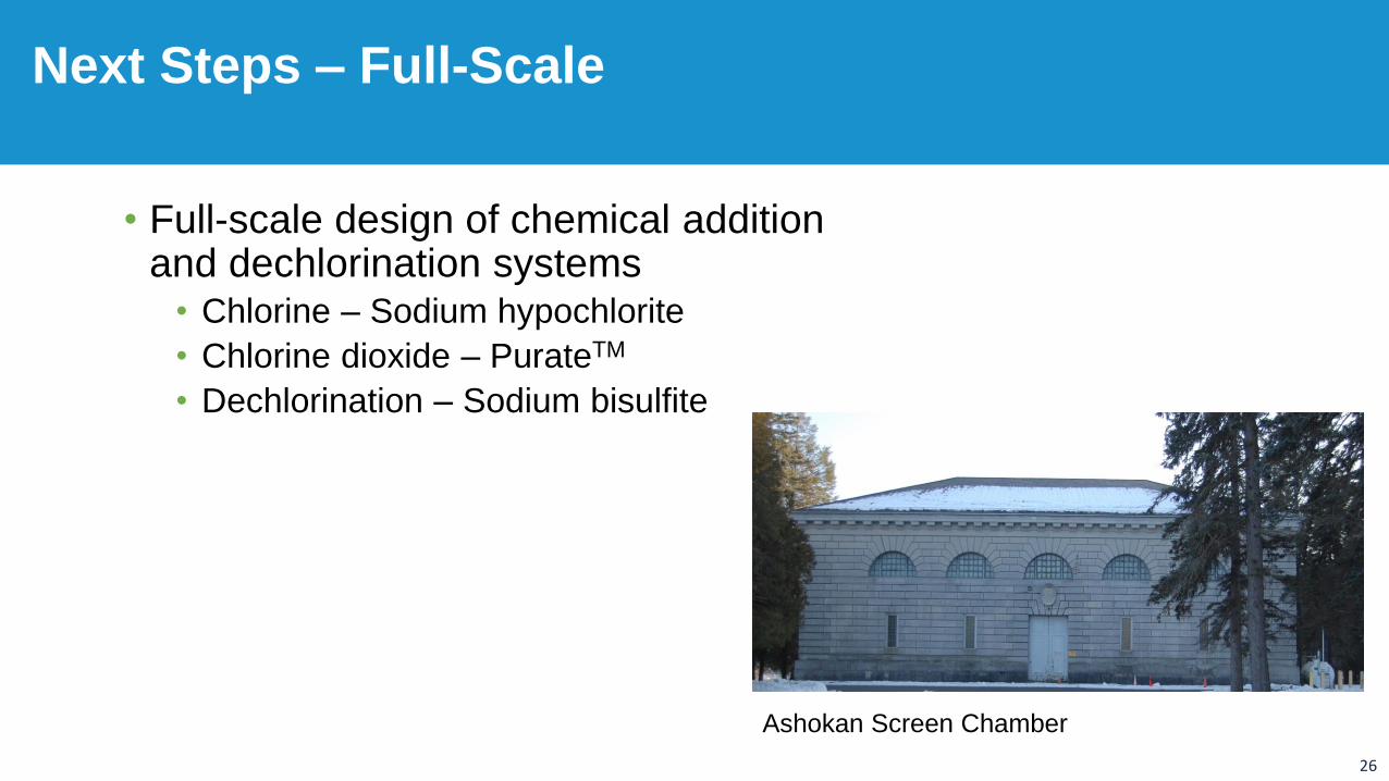
• Full-scale design of chemical addition and dechlorination systems
• Chlorine – Sodium hypochlorite
• Chlorine dioxide – PurateTM
• Dechlorination – Sodium bisulfite
Next Steps – Full-Scale
Ashokan Screen Chamber
27
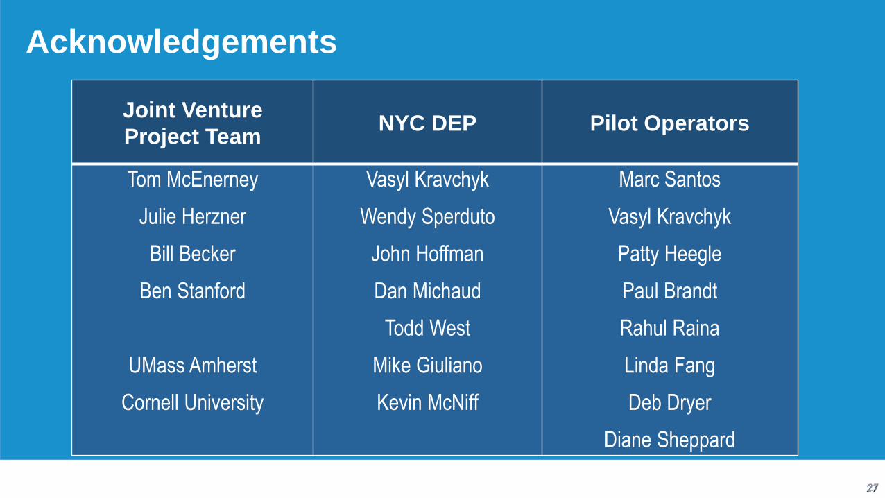
Acknowledgements
27
Joint Venture
Project Team NYC DEP Pilot Operators
Tom McEnerney
Julie Herzner
Bill Becker
Ben Stanford
UMass Amherst
Cornell University
Vasyl Kravchyk
Wendy Sperduto
John Hoffman
Dan Michaud
Todd West
Mike Giuliano
Kevin McNiff
Marc Santos
Vasyl Kravchyk
Patty Heegle
Paul Brandt
Rahul Raina
Linda Fang
Deb Dryer
Diane Sheppard


![PMP 패키지 pmp 패키지 pmp패키지과정은[pmp 주중반] 또는[pmp 주말반] 수강과함께[시험응시료]를함께제공하는과정니다. pmp 자격시험주관처인미국pmi](https://img.pdfslide.net/doc/110x75/5e9830a17f8afd798b62141f/pmp-oe-pmp-oe-pmpoeepmp-e-eepmp-ee.jpg)
