Embed Size (px)
Citation preview
© 2014 IJEDR | Volume 2, Issue 2 | ISSN: 2321-9939
IJEDR1402053 International Journal of Engineering Development and Research (www.ijedr.org) 1610
Vector Control of PM Synchronous Motor Drive
System Using Hysteresis Current Controller 1Rajesh P. Nathwani,
2Hitesh M. Karkar
1M.E.(Electrical) Student,
2Assistant Prof.
1Electrical Department,
1Atmiya institute of technology & science , Rajkot, India.
[email protected], [email protected]
________________________________________________________________________________________________________
Abstract: This paper describes PM SYNCHRONOUS MOTOR Control techniques used in AC drives prevailing in
Contemporary market viz, Scalar Control & Vector control(field oriented control).The underlying operating Principle of
control schemes are described and indirect vector controlled PM synchronous motor drive has been simulated in
MATLAB/Simulink environment. Also hysteresis band pulse width modulated inverter (current controlled VSI) has been
implemented using simpower system blocks & the same is used to supply the PM synchronous motor as per the indirect
vector control scheme thereby implementing complete indirect vector control drive in closed loop operation.
Index Terms- indirect Vector control, PM synchronous motor, Hysteresis Current controller, Closed loop motor drive.
________________________________________________________________________________________________________
I.INTRODUCTION
The last decade has seen rapid growth in the field of electrical drives. This growth can be attributed mainly to the advantages
offered by both power and signal electronics; hence giving rise to powerful microcontroller and DSP. These technological
improvements have allowed the development of very effective AC drives controls.
Now days many industrial applications which require electrical drive demand precise speed and torque control, to increase
production quality. More ever proper control of these drives using modern control schemes also improves systems efficiency. For
application requiring precise control previously DC drives preferred because of their inherent ability to give independent speed
and torque control. But these drives have higher maintenance costs because of brush and commutator construction.
In this paper Vector control technique with Voltage source inverter (VSI) for speed control of PM synchronous motor has
been discussed. These drives are simulated in MATLAB and tracking of reference speed and torque has been observed.
II.PM SYNCHRONOUS MOTOR DRIVE SYSTEM
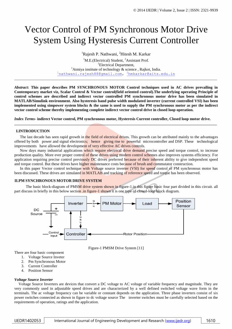
The basic block-diagram of PMSM drive system shown in figure-1.in this figure basic four part divided in this circuit. all
part discuss in briefly in this below section .in figure-1 shown it is one type of closed-loop block diagram.
Figure-1 PMSM Drive System [11]
There are four basic component
1. Voltage Source Inveter
2. Pm Synchronous Motor
3. Current Controller
4. Position Sensor
Voltage Source Inverter
Voltage Source Inverters are devices that convert a DC voltage to AC voltage of variable frequency and magnitude. They are
very commonly used in adjustable speed drives and are characterized by a well defined switched voltage wave form in the
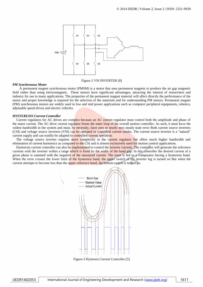
terminals. The ac voltage frequency can be variable or constant depends on the application. Three phase inverters consist of six
power switches connected as shown in figure to dc voltage source The inverter switches must be carefully selected based on the
requirements of operation, ratings and the application.
© 2014 IJEDR | Volume 2, Issue 2 | ISSN: 2321-9939
IJEDR1402053 International Journal of Engineering Development and Research (www.ijedr.org) 1611
Figure-2 VSI INVERTER [8]
PM Synchronous Motor
A permanent magnet synchronous motor (PMSM) is a motor that uses permanent magnets to produce the air gap magnetic
field rather than using electromagnets. These motors have significant advantages, attracting the interest of researchers and
industry for use in many applications. The properties of the permanent magnet material will affect directly the performance of the
motor and proper knowledge is required for the selection of the materials and for understanding PM motors. Permanent magnet
(PM) synchronous motors are widely used in low and mid power applications such as computer peripheral equipments, robotics,
adjustable speed drives and electric vehicles.
HYSTERESIS Current Controller Current regulators for AC drives are complex because an AC current regulator must control both the amplitude and phase of
the stator current. The AC drive current regulator forms the inner loop of the overall motion controller. As such, it must have the
widest bandwidth in the system and must, by necessity, have zero or nearly zero steady-state error Both current source inverters
(CSI) and voltage source inverters (VSI) can be operated in controlled current modes. The current source inverter is a "natural"
current supply and can readily be adapted to controlled current operation.
The voltage source inverter requires more complexity in the current regulator but offers much higher bandwidth and
elimination of current harmonics as compared to the CSI and is almost exclusively used for motion control applications.
Hysteresis current controller can also be implemented to control the inverter currents. The controller will generate the reference
currents with the inverter within a range which is fixed by the width of the band gap. In this controller the desired current of a
given phase is summed with the negative of the measured current. The error is fed to a comparator having a hysteresis band.
When the error crosses the lower limit of the hysteresis band, the upper switch of the inverter leg is turned on But when the
current attempts to become less than the upper reference band, the bottom switch is turned on.
Figure-3 Hystresis Current Controller.[5]
© 2014 IJEDR | Volume 2, Issue 2 | ISSN: 2321-9939
IJEDR1402053 International Journal of Engineering Development and Research (www.ijedr.org) 1612
The hysteresis band with the actual current and the resulting gate signals. This controller does not have a specific switching
frequency and changes continuously but it is related with the band width shown in figure-3.
Position Sensor
Operation of permanent magnet synchronous motors requires position sensors in the rotor shaft when operated without damper
winding. The need of knowing the rotor position requires the development of devices for position measurement. There are four
main devices for the measurement of position, the potentiometer, linear variable differential transformer, optical encoder and
resolvers. The ones most commonly used for motors are encoders and revolvers. Depending on the application and performance
desired by the motor a position sensor with the required accuracy can be selected.
III.VECTOR CONTROL TECHNIQUE
The PMSM control is equivalent to that of the dc motor by a decoupling control known as field oriented control or vector
control. The vector control separates the torque component of current and flux channels in the motor through its stator excitation.
The vector control strategy is somewhat similar to that of the induction motor vector control, except for the following:
The slip frequency is zero because the machine always runs at synchronous speed.
The magnetizing current Ids =0 because the rotor flux is supplied by the PM.
The unit vector generated from an absolute position sensor because, the unlike slipping poles of an induction motor, the poles
are fixed on the rotor.
The basically two method of vector control.(1) Direct method (2) indirect method This method are different essentially by how
the unit vector (cosθe , sinθe) is generated for control. It should be mention here that the orientation of Ids with rotor flux ,air gap
flux or stator flux is possible in vector control. The indirect vector control method is used for the PM synchronous motor drive
systems.
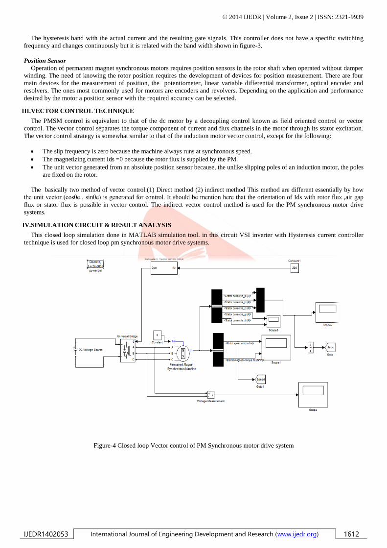
IV.SIMULATION CIRCUIT & RESULT ANALYSIS
This closed loop simulation done in MATLAB simulation tool. in this circuit VSI inverter with Hysteresis current controller
technique is used for closed loop pm synchronous motor drive systems.
Figure-4 Closed loop Vector control of PM Synchronous motor drive system
© 2014 IJEDR | Volume 2, Issue 2 | ISSN: 2321-9939
IJEDR1402053 International Journal of Engineering Development and Research (www.ijedr.org) 1613
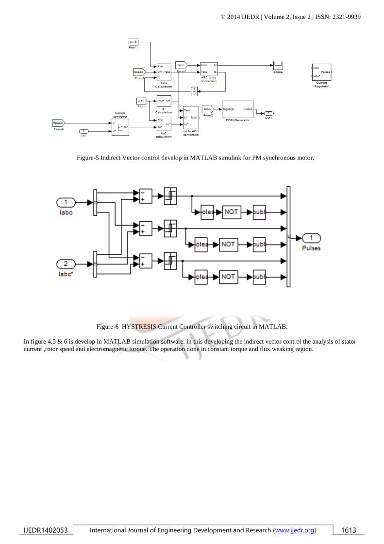
Figure-5 Indirect Vector control develop in MATLAB simulink for PM synchronous motor.
Figure-6 HYSTRESIS Current Controller switching circuit in MATLAB.
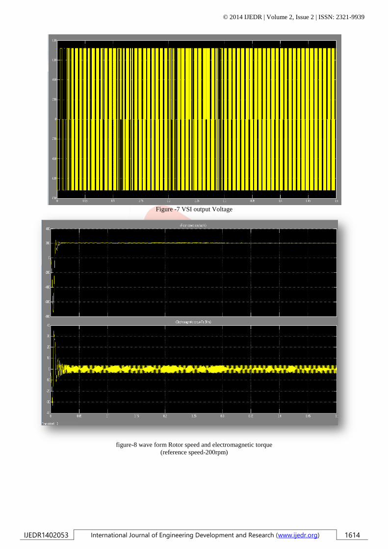
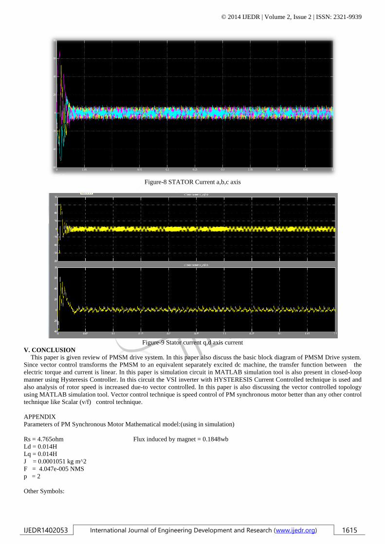
In figure 4,5 & 6 is develop in MATLAB simulation software. in this developing the indirect vector control the analysis of stator
current ,rotor speed and electromagnetic torque. The operation done in constant torque and flux weaking region.
© 2014 IJEDR | Volume 2, Issue 2 | ISSN: 2321-9939
IJEDR1402053 International Journal of Engineering Development and Research (www.ijedr.org) 1614
Figure -7 VSI output Voltage
figure-8 wave form Rotor speed and electromagnetic torque
(reference speed-200rpm)
© 2014 IJEDR | Volume 2, Issue 2 | ISSN: 2321-9939
IJEDR1402053 International Journal of Engineering Development and Research (www.ijedr.org) 1615
Figure-8 STATOR Current a,b,c axis
Figure-9 Stator current q,d axis current
V. CONCLUSION
This paper is given review of PMSM drive system. In this paper also discuss the basic block diagram of PMSM Drive system.
Since vector control transforms the PMSM to an equivalent separately excited dc machine, the transfer function between the
electric torque and current is linear. In this paper is simulation circuit in MATLAB simulation tool is also present in closed-loop
manner using Hysteresis Controller. In this circuit the VSI inverter with HYSTERESIS Current Controlled technique is used and
also analysis of rotor speed is increased due-to vector controlled. In this paper is also discussing the vector controlled topology
using MATLAB simulation tool. Vector control technique is speed control of PM synchronous motor better than any other control
technique like Scalar (v/f) control technique.
APPENDIX
Parameters of PM Synchronous Motor Mathematical model:(using in simulation)
Rs = 4.765ohm Flux induced by magnet = 0.1848wb
Ld = 0.014H
Lq = 0.014H
J = 0.0001051 kg m^2
F = 4.047e-005 NMS
p = 2
Other Symbols:
© 2014 IJEDR | Volume 2, Issue 2 | ISSN: 2321-9939
IJEDR1402053 International Journal of Engineering Development and Research (www.ijedr.org) 1616
Rs = Stator resistance
Ld = d- axis inductance
Lq = q- axis inductance
J = Rotor interia
F = Friction factor
p = Poles pairs
REFERNCES
[1] D. P. M. Cahill and B. Adkins, “The permanent magnet synchronous motor,” Proc. Inst. Elec. Eng., vol. 109, part
A, no. 48, pp. 483-491, Dec. 1962.
[2] R. Krishnan and A. J. Beutler, “Performance and design of an axial field permanent magnet synchronous motor servo
drive,” in Proc.IEEE Ind. Appl. Soc. Annu. Meeting, 1985, pp. 634-640.
[3] E. Richter, T. J. E. Miller, T. W. Neumann, and T. L. Hudson, “Theferrite PM ac motor-A technical and economic
assessment, ” IEEETrans. Ind. Appl., vol. IA-21, no. 4, pp. 644-650, May/June 1985.
[4] B. Honsinger, “Permanent magnet machines: Asynchronous operation,” IEEE Trans. PowerApp. Sysr., vol. PAS-99, no.
4, pp.
[5] T. J. E. Miller, “Transient performance of permanent magnet machines,” in Proc. Ind. Appl. Soc. Annu. Meeting, 1981,
pp. 500-502.
[6] W. Leonard, Control of Electrical Drives. New York: Springer-Verlag, 1984.
[7] G. Pfaff, A. Weschta, and A. Wick, “Design and experimental results of a brushless ac servo drive,” in Proc. IEEE Ind.
Appl. Soc. Annu. Meeting, 1982, pp. 692-697.
[8] R. Krishnan, “Analysis of electronically controlled motor drives,” class notes, Virginia Polytechnic Inst. and State Univ.,
Blacksburg,1986.
[9] M. Lajoie-Mazenc, C. Villanueva, and J. Hector, “Study and implementation of hysteresis controlled inverter on a
permanent magnet synchronous machine,” IEEE Trans. Ind. Appl., vol. IA-21, no. 2, pp. 408-413, Mar./Apr. 1985.
[10] P. Enjeti, J. F. Lindsay, and M. H. Rashid, “Stability and dynamic performance of variable speed permanent magnet
synchronous motors,” in Proc. IECON, 1985, pp. 749-754.
[11] Pillay and R. Krishnan, “Control characteristics and speed controller design for a high-performance permanent magnet
synchronous motor drive,” in Proc. IEEE 1987 Power Electronics Specialists’ Cony., 1987, pp. 598-606.
[12] “Application characteristics of permanent magnet synchronous and brushless dc motors for servo drives,” in Proc. Ind.
Appl. Soc. Annu. Meeting, 1987, pp. 380-390.