Embed Size (px)
Citation preview
SAE Technical Standards Board Rules provide that: “This report is published by SAE to advance the state of technical and engineering sciences. The use of this report is entirelyvoluntary, and its applicability and suitability for any particular use, including any patent infringement arising therefrom, is the sole responsibility of the user.”
SAE reviews each technical report at least every five years at which time it may be reaffirmed, revised, or cancelled. SAE invites your written comments and suggestions.
QUESTIONS REGARDING THIS DOCUMENT: (724) 772-8512 FAX: (724) 776-0243TO PLACE A DOCUMENT ORDER; (724) 776-4970 FAX: (724) 776-0790
SAE WEB ADDRESS http://www.sae.org
Copyright 1968 Society of Automotive Engineers, Inc.All rights reserved. Printed in U.S.A.
SURFACEVEHICLE
400 Commonwealth Drive, Warrendale, PA 15096-0001STANDARD
Submitted for recognition as an American National Standard
J492REV.
MAY68
Issued 1928-02Revised 1968-05
Superseding J492 JUN61
(R) RIVETS AND RIVETING
Foreword—This Document has also changed to comply with the new SAE Technical Standards Board format.
1. Scope
2. References—There are no referenced publications specified herein.
3. General Specifications for Small Solid Rivets
3.1 General—This small solid rivet standard covers the complete general and dimensional data for flat head, panhead, button head, truss head, countersunk head, copper’s, tinner’s and belt rivets. Design and assembly dataare given in the Appendix—Rivet Selection and Design Considerations.
The inclusion of dimensional data in this standard is not intended to imply that all of the products described arestock production sizes. Consumers are requested to consult with manufacturers concerning stock productionsizes.
3.2 Tolerances—The tolerances given on the dimensional tables are those for rivets made by the normal coldheading process. The tolerance for rivets made by the hot heading or forging process shall be as agreed uponbetween the purchaser and supplier.
3.3 Heads—Because the heads of these rivets are not machined or trimmed, the circumference may be slightlyirregular and the edges may be rounded or flat.
3.4 Underhead Fillets—Rivets, other than countersunk type, shall be furnished with a definite fillet under thehead but radius of fillet shall not exceed 10% of maximum shank diameter or 0.03 in., whichever is the smaller.
3.5 Material—Rivets shall be steel, copper, brass, aluminum, or other metals as specified by purchaser.
Suitable material for steel small solid rivets is covered by SAE Recommended Practice, Mechanical andChemical Requirements for Non-threaded Fasteners—SAE J430.
Requirements of rivets made from other materials shall be as agreed upon between the purchaser andsupplier.
SAE J492 Revised MAY68
-2-
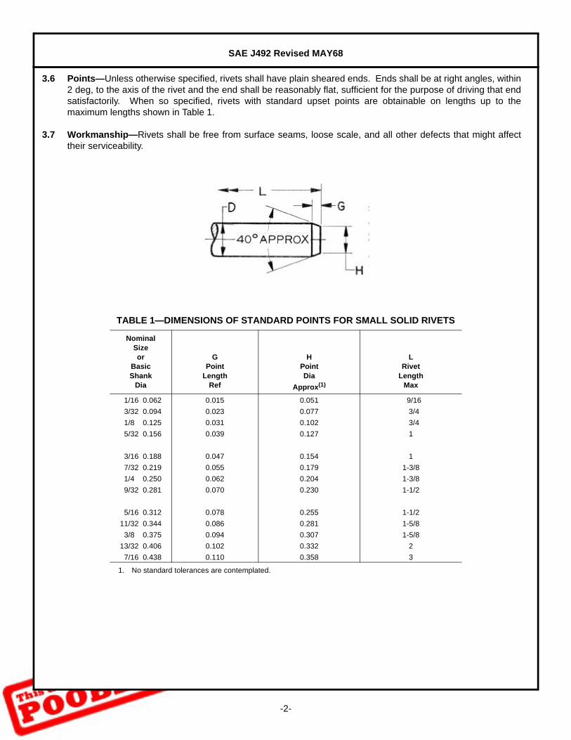
3.6 Points—Unless otherwise specified, rivets shall have plain sheared ends. Ends shall be at right angles, within2 deg, to the axis of the rivet and the end shall be reasonably flat, sufficient for the purpose of driving that endsatisfactorily. When so specified, rivets with standard upset points are obtainable on lengths up to themaximum lengths shown in Table 1.
3.7 Workmanship—Rivets shall be free from surface seams, loose scale, and all other defects that might affecttheir serviceability.
TABLE 1—DIMENSIONS OF STANDARD POINTS FOR SMALL SOLID RIVETS
NominalSizeor
BasicShank
Dia
GPoint
LengthRef
HPointDia
Approx(1)
1. No standard tolerances are contemplated.
LRivet
LengthMax
1/16 0.062 0.015 0.051 9/16
3/32 0.094 0.023 0.077 3/4
1/8 0.125 0.031 0.102 3/4
5/32 0.156 0.039 0.127 1
3/16 0.188 0.047 0.154 1
7/32 0.219 0.055 0.179 1-3/8
1/4 0.250 0.062 0.204 1-3/8
9/32 0.281 0.070 0.230 1-1/2
5/16 0.312 0.078 0.255 1-1/2
11/32 0.344 0.086 0.281 1-5/8
3/8 0.375 0.094 0.307 1-5/8
13/32 0.406 0.102 0.332 2
7/16 0.438 0.110 0.358 3
SAE J492 Revised MAY68
-3-
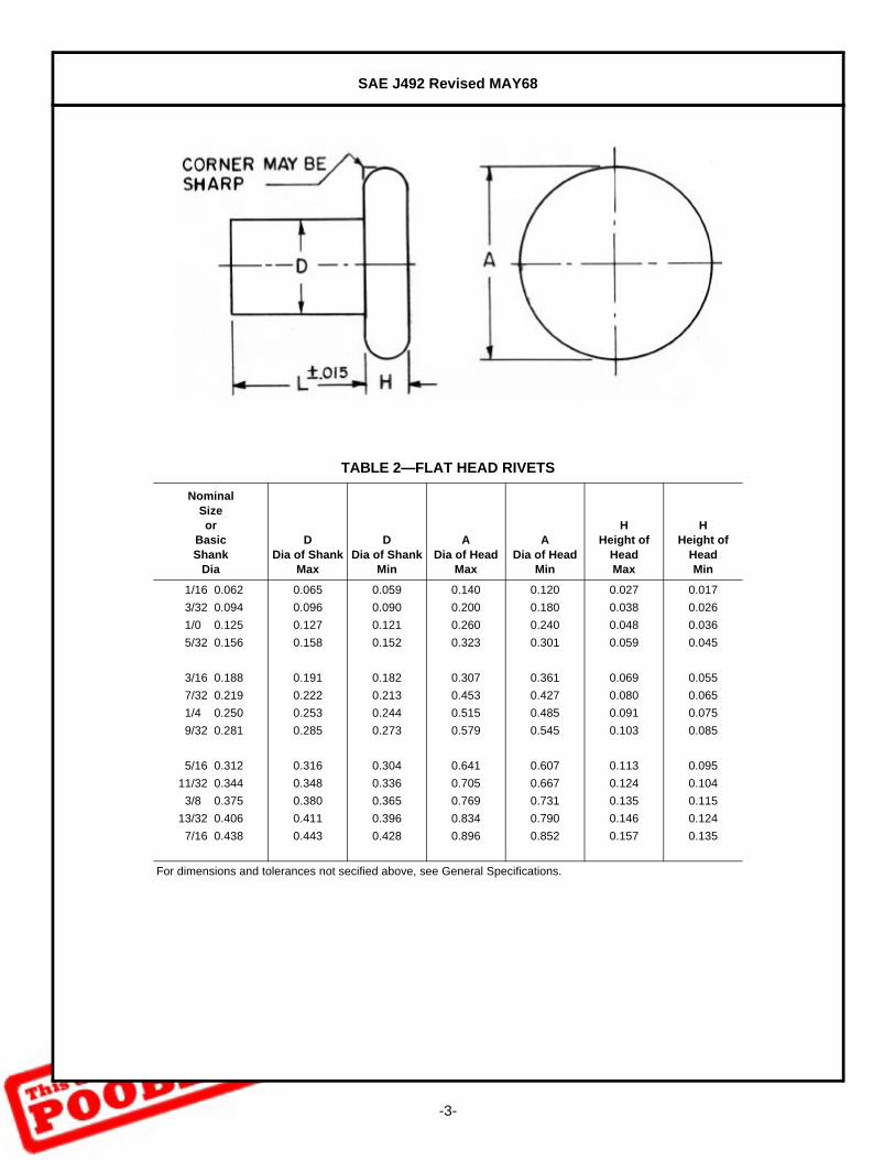
TABLE 2—FLAT HEAD RIVETS
NominalSizeor
BasicShank
Dia
DDia of Shank
Max
DDia of Shank
Min
ADia of Head
Max
ADia of Head
Min
HHeight of
HeadMax
HHeight of
HeadMin
1/16 0.062 0.065 0.059 0.140 0.120 0.027 0.017
3/32 0.094 0.096 0.090 0.200 0.180 0.038 0.026
1/0 0.125 0.127 0.121 0.260 0.240 0.048 0.036
5/32 0.156 0.158 0.152 0.323 0.301 0.059 0.045
3/16 0.188 0.191 0.182 0.307 0.361 0.069 0.055
7/32 0.219 0.222 0.213 0.453 0.427 0.080 0.065
1/4 0.250 0.253 0.244 0.515 0.485 0.091 0.075
9/32 0.281 0.285 0.273 0.579 0.545 0.103 0.085
5/16 0.312 0.316 0.304 0.641 0.607 0.113 0.095
11/32 0.344 0.348 0.336 0.705 0.667 0.124 0.104
3/8 0.375 0.380 0.365 0.769 0.731 0.135 0.115
13/32 0.406 0.411 0.396 0.834 0.790 0.146 0.124
7/16 0.438 0.443 0.428 0.896 0.852 0.157 0.135
For dimensions and tolerances not secified above, see General Specifications.
SAE J492 Revised MAY68
-4-
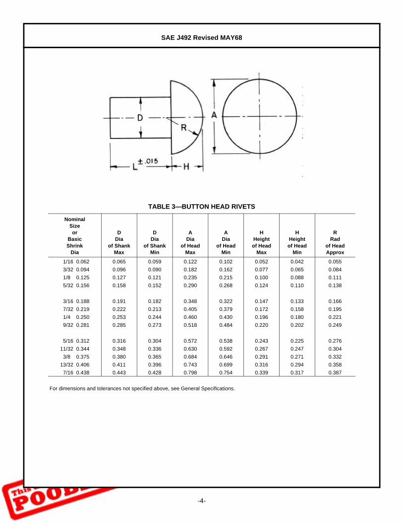
TABLE 3—BUTTON HEAD RIVETS
NominalSizeor
BasicShrink
Dia
DDia
of ShankMax
DDia
of ShankMin
ADia
of HeadMax
ADia
of HeadMin
HHeightof Head
Max
HHeightof Head
Min
RRad
of HeadApprox
1/16 0.062 0.065 0.059 0.122 0.102 0.052 0.042 0.055
3/32 0.094 0.096 0.090 0.182 0.162 0.077 0.065 0.084
1/8 0.125 0.127 0.121 0.235 0.215 0.100 0.088 0.111
5/32 0.156 0.158 0.152 0.290 0.268 0.124 0.110 0.138
3/16 0.188 0.191 0.182 0.348 0.322 0.147 0.133 0.166
7/32 0.219 0.222 0.213 0.405 0.379 0.172 0.158 0.195
1/4 0.250 0.253 0.244 0.460 0.430 0.196 0.180 0.221
9/32 0.281 0.285 0.273 0.518 0.484 0.220 0.202 0.249
5/16 0.312 0.316 0.304 0.572 0.538 0.243 0.225 0.276
11/32 0.344 0.348 0.336 0.630 0.592 0.267 0.247 0.304
3/8 0.375 0.380 0.365 0.684 0.646 0.291 0.271 0.332
13/32 0.406 0.411 0.396 0.743 0.699 0.316 0.294 0.358
7/16 0.438 0.443 0.428 0.798 0.754 0.339 0.317 0.387
For dimensions and tolerances not specified above, see General Specifications.
SAE J492 Revised MAY68
-5-
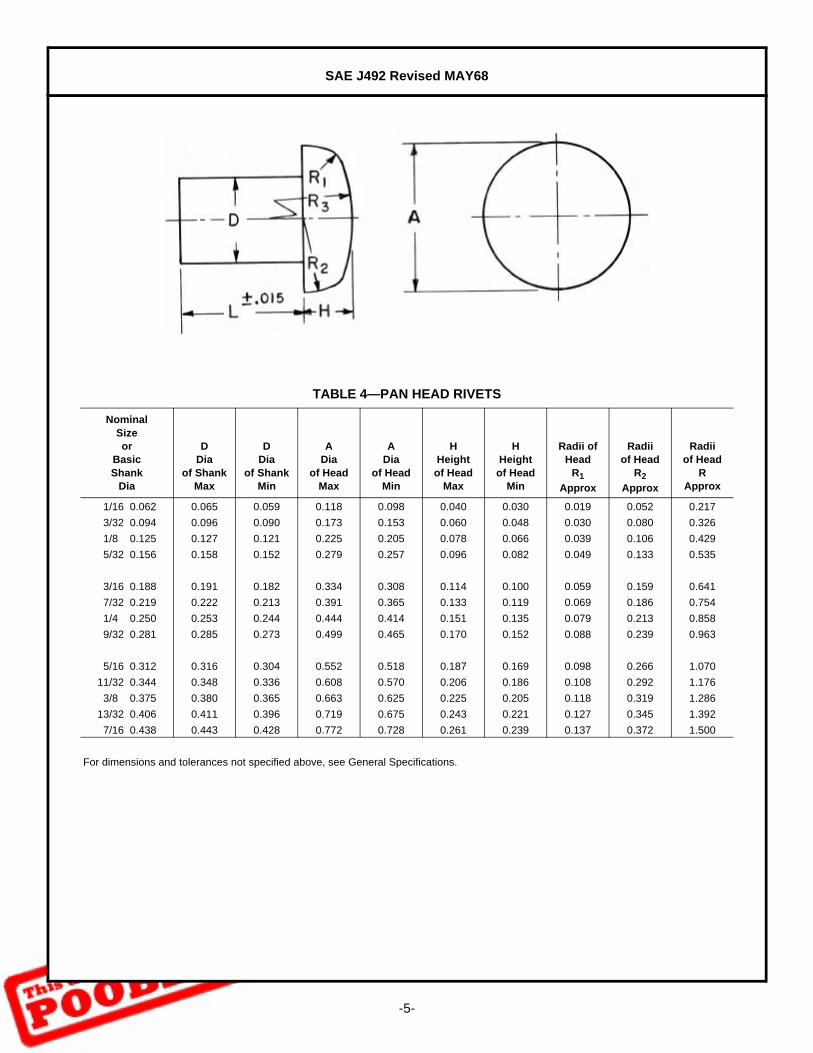
TABLE 4—PAN HEAD RIVETS
NominalSizeor
BasicShank
Dia
DDia
of ShankMax
DDia
of ShankMin
ADia
of HeadMax
ADia
of HeadMin
HHeightof Head
Max
HHeightof Head
Min
Radii of Head
R1
Approx
Radiiof Head
R2
Approx
Radiiof Head
RApprox
1/16 0.062 0.065 0.059 0.118 0.098 0.040 0.030 0.019 0.052 0.217
3/32 0.094 0.096 0.090 0.173 0.153 0.060 0.048 0.030 0.080 0.326
1/8 0.125 0.127 0.121 0.225 0.205 0.078 0.066 0.039 0.106 0.429
5/32 0.156 0.158 0.152 0.279 0.257 0.096 0.082 0.049 0.133 0.535
3/16 0.188 0.191 0.182 0.334 0.308 0.114 0.100 0.059 0.159 0.641
7/32 0.219 0.222 0.213 0.391 0.365 0.133 0.119 0.069 0.186 0.754
1/4 0.250 0.253 0.244 0.444 0.414 0.151 0.135 0.079 0.213 0.858
9/32 0.281 0.285 0.273 0.499 0.465 0.170 0.152 0.088 0.239 0.963
5/16 0.312 0.316 0.304 0.552 0.518 0.187 0.169 0.098 0.266 1.070
11/32 0.344 0.348 0.336 0.608 0.570 0.206 0.186 0.108 0.292 1.176
3/8 0.375 0.380 0.365 0.663 0.625 0.225 0.205 0.118 0.319 1.286
13/32 0.406 0.411 0.396 0.719 0.675 0.243 0.221 0.127 0.345 1.392
7/16 0.438 0.443 0.428 0.772 0.728 0.261 0.239 0.137 0.372 1.500
For dimensions and tolerances not specified above, see General Specifications.
SAE J492 Revised MAY68
-6-
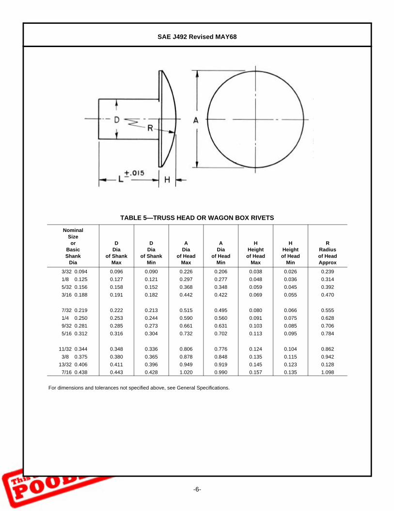
TABLE 5—TRUSS HEAD OR WAGON BOX RIVETS
NominalSizeor
BasicShank
Dia
DDia
of ShankMax
DDia
of ShankMin
ADia
of HeadMax
ADia
of HeadMin
HHeightof Head
Max
HHeightof Head
Min
RRadiusof HeadApprox
3/32 0.094 0.096 0.090 0.226 0.206 0.038 0.026 0.239
1/8 0.125 0.127 0.121 0.297 0.277 0.048 0.036 0.314
5/32 0.156 0.158 0.152 0.368 0.348 0.059 0.045 0.392
3/16 0.188 0.191 0.182 0.442 0.422 0.069 0.055 0.470
7/32 0.219 0.222 0.213 0.515 0.495 0.080 0.066 0.555
1/4 0.250 0.253 0.244 0.590 0.560 0.091 0.075 0.628
9/32 0.281 0.285 0.273 0.661 0.631 0.103 0.085 0.706
5/16 0.312 0.316 0.304 0.732 0.702 0.113 0.095 0.784
11/32 0.344 0.348 0.336 0.806 0.776 0.124 0.104 0.862
3/8 0.375 0.380 0.365 0.878 0.848 0.135 0.115 0.942
13/32 0.406 0.411 0.396 0.949 0.919 0.145 0.123 0.128
7/16 0.438 0.443 0.428 1.020 0.990 0.157 0.135 1.098
For dimensions and tolerances not specified above, see General Specifications.

SAE J492 Revised MAY68
-7-
TABLE 6—COUNTERSUNK HEAD RIVETS
NominalSizeor
BasicShank
Dia
DDia
of ShankMax
DDia
of ShankMin
ADia
of HeadMax Sharp
ADia
of HeadAbs Min
H(1)
Heightof
Head
1. Height of head, H, is given for construction purposes only. Variations in this dimension are controlled by the diameters A and D and the included angle of the head.For dimensions and tolerances not specified above, see General Specifications.
1/16 0.062 0.065 0.059 0.118 0.110 0.027
3/32 0.094 0.096 0.090 0.176 0.163 0.040
1/8 0.125 0.127 0.121 0.235 0.217 0.053
5/32 0.156 0.158 0.152 0.293 0.272 0.066
3/16 0.188 0.191 0.182 0.351 0.326 0.079
7/32 0.219 0.222 0.213 0.413 0.384 0.094
1/4 0.250 0.253 0.244 0.469 0.437 0.106
9/32 0.281 0.285 0.273 0.528 0.491 0.119
5/16 0.312 0.316 0.304 0.588 0.547 0.133
11/32 0.344 0.348 0.336 0.646 0.602 0.146
3/8 0.375 0.380 0.365 0.704 0.656 0.159
13/32 0.406 0.411 0.396 0.763 0.710 0.172
7/16 0.438 0.443 0.428 0.823 0.765 0.186

SAE J492 Revised MAY68
-8-
TABLE 7—TINNERS’ RIVETS
Nominal
Size(1)
1. Nominal size refers to the approximate weight of 1,000 rivets.For dimensions and tolerances not specified above, see General Specifications.
DDia
of ShankMax
DDia
of ShankMin
ADia
of HeadMax
ADia
of HeadMin
HHeightof Head
Max
HHeightof Head
MinLength
MaxLength
Min
6 oz 0.081 0.075 0.213 0.193 0.028 0.016 0.135 0.115
8 oz 0.091 0.085 0.225 0.205 0.036 0.024 0.166 0.146
10 oz 0.097 0.091 0.250 0.230 0.037 0.025 0.182 0.162
12 oz 0.107 0.101 0.265 0.245 0.037 0.025 0.198 0.178
14 oz 0.111 0.105 0.275 0.255 0.038 0.026 0.198 0.178
1 lb 0.113 0.107 0.285 0.265 0.040 0.028 0.213 0.193
1-1/4 lb 0.122 0.116 0.295 0.275 0.045 0.033 0.229 0.209
1-1/2 lb 0.132 0.126 0.316 0.294 0.046 0.034 0.244 0.224
1-3/4 lb 0.136 0.130 0.331 0.309 0.049 0.035 0.260 0.240
2 lb 0.146 0.140 0.341 0.319 0.050 0.036 0.276 0.256
2-1/2 lb 0.150 0.144 0.311 0.289 0.069 0.055 0.291 0.271
3 lb 0.163 0.154 0.329 0.303 0.073 0.059 0.323 0.303
3-1/2 lb 0.168 0.159 0.348 0.322 0.074 0.060 0.338 0.318
4 lb 0.179 0.170 0.368 0.342 0.076 0.062 0.354 0.334
5 lb 0.190 0.181 0.388 0.362 0.084 0.070 0.385 0.365
6 lb 0.206 0.197 0.419 0.393 0.090 0.076 0.401 0.381
7 lb 0.223 0.214 0.431 0.405 0.094 0.080 0.416 0.396
8 lb 0.227 0.218 0.475 0.445 0.101 0.085 0.448 0.428
9 lb 0.241 0.232 0.490 0.460 0.103 0.087 0.463 0.443
10 lb 0.241 0.232 0.505 0.475 0.104 0.088 0.479 0.459
12 lb 0.263 0.251 0.532 0.498 0.108 0.090 0.510 0.490
14 lb 0.288 0.276 0.577 0.543 0.113 0.095 0.525 0.505
16 lb 0.304 0.292 0.597 0.563 0.128 0.110 0.541 0.521
18 lb 0.347 0.335 0.706 0.668 0.156 0.136 0.603 0.583
SAE J492 Revised MAY68
-9-
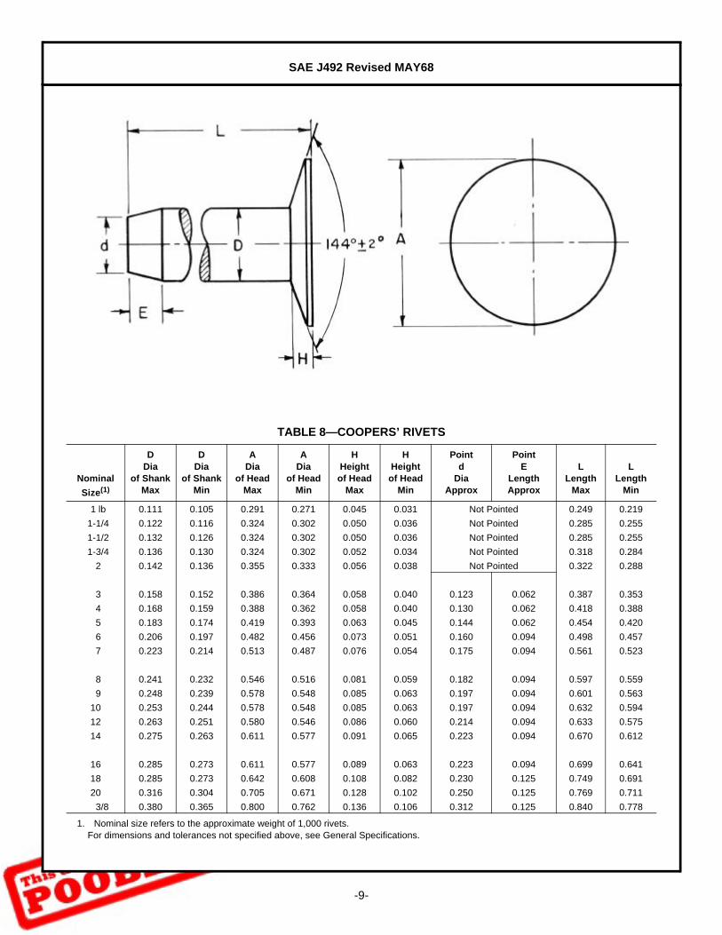
TABLE 8—COOPERS’ RIVETS
Nominal
Size(1)
1. Nominal size refers to the approximate weight of 1,000 rivets.For dimensions and tolerances not specified above, see General Specifications.
DDia
of ShankMax
DDia
of ShankMin
ADia
of HeadMax
ADia
of HeadMin
HHeightof Head
Max
HHeightof Head
Min
Pointd
DiaApprox
PointE
LengthApprox
LLength
Max
LLength
Min
1 lb 0.111 0.105 0.291 0.271 0.045 0.031 Not Pointed 0.249 0.219
1-1/4 0.122 0.116 0.324 0.302 0.050 0.036 Not Pointed 0.285 0.255
1-1/2 0.132 0.126 0.324 0.302 0.050 0.036 Not Pointed 0.285 0.255
1-3/4 0.136 0.130 0.324 0.302 0.052 0.034 Not Pointed 0.318 0.284
2 0.142 0.136 0.355 0.333 0.056 0.038 Not Pointed 0.322 0.288
3 0.158 0.152 0.386 0.364 0.058 0.040 0.123 0.062 0.387 0.353
4 0.168 0.159 0.388 0.362 0.058 0.040 0.130 0.062 0.418 0.388
5 0.183 0.174 0.419 0.393 0.063 0.045 0.144 0.062 0.454 0.420
6 0.206 0.197 0.482 0.456 0.073 0.051 0.160 0.094 0.498 0.457
7 0.223 0.214 0.513 0.487 0.076 0.054 0.175 0.094 0.561 0.523
8 0.241 0.232 0.546 0.516 0.081 0.059 0.182 0.094 0.597 0.559
9 0.248 0.239 0.578 0.548 0.085 0.063 0.197 0.094 0.601 0.563
10 0.253 0.244 0.578 0.548 0.085 0.063 0.197 0.094 0.632 0.594
12 0.263 0.251 0.580 0.546 0.086 0.060 0.214 0.094 0.633 0.575
14 0.275 0.263 0.611 0.577 0.091 0.065 0.223 0.094 0.670 0.612
16 0.285 0.273 0.611 0.577 0.089 0.063 0.223 0.094 0.699 0.641
18 0.285 0.273 0.642 0.608 0.108 0.082 0.230 0.125 0.749 0.691
20 0.316 0.304 0.705 0.671 0.128 0.102 0.250 0.125 0.769 0.711
3/8 0.380 0.365 0.800 0.762 0.136 0.106 0.312 0.125 0.840 0.778
SAE J492 Revised MAY68
-10-
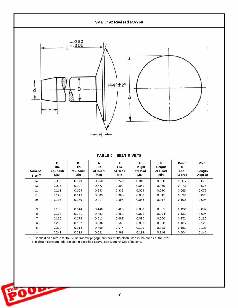
TABLE 9—BELT RIVETS
Nominal
Size(1)
1. Nominal size refers to the Stubs iron wirge gage number of the stock used in the shank of the rivet.For dimensions and tolerances not specified above, see General Specifications.
DDia
of ShankMax
DDia
of ShankMin
ADia
of HeadMax
ADia
of HeadMin
HHeightof Head
Max
HHeightof Head
Min
Pointd
DiaApprox
PointE
LengthApprox
14 0.085 0.079 0.260 0.240 0.042 0.030 0.065 0.078
13 0.097 0.091 0.322 0.302 0.051 0.039 0.073 0.078
12 0.111 0.105 0.353 0.333 0.054 0.040 0.083 0.078
11 0.122 0.116 0.383 0.363 0.059 0.045 0.097 0.078
10 0.136 0.130 0.417 0.395 0.065 0.047 0.109 0.094
9 0.150 0.144 0.448 0.426 0.069 0.051 0.122 0.094
8 0.167 0.161 0.481 0.455 0.072 0.054 0.135 0.094
7 0.183 0.174 0.513 0.487 0.075 0.056 0.151 0.125
6 0.206 0.197 0.606 0.580 0.090 0.068 0.165 0.125
5 0.223 0.214 0.700 0.674 0.105 0.083 0.185 0.125
4 0.241 0.232 0.921 0.893 0.138 0.116 0.204 0.141
SAE J492 Revised MAY68
-11-
4. General Specifications For Tubular Rivets
4.1 General—This tubular rivet standard covers the complete general and dimensional data for oval head, trusshead, flat head, 90- and 120-deg countersunk head semitubular rivets and oval head, truss head andcountersunk head full tubular rivets. Design and assembly data are given in the Appendix—Rivet Selectionand Design Considerations.
The inclusion of dimensional data in this standard is not intended to imply that all of the products described arestock production sizes. Consumers are requested to consult with manufacturers concerning stock productionsizes.
4.2 Heads—The bearing surface of flat, oval, and truss head rivets shall be at right angles to the axis of the bodywithin 2 deg. Heads of all tubular rivets shall not be eccentric with the shank beyond a tolerance of 3% of themaximum head diameter. Because the heads are not machined or trimmed, the circumference may be slightlyirregular and the edges rounded or flat.
4.3 Underhead Fillets—Rivets, other than countersunk type, shall be furnished with a definite fillet under the headbut radius of fillet shall not exceed 10% of maximum shank diameter.
4.4 Material—Tubular rivets shall be low carbon steel, or brass, standard with manufacturer; or stainless steel,aluminum, copper, or other metals as agreed upon between the purchaser and supplier.
4.5 Length—Length of rivets shall be measured as indicated in the illustrations for each head style. Tubular rivetsare available in length increments specified in Table 10.
Tolerance on length of tubular rivets shall be as specified in Table 11.
4.6 Workmanship—Tubular rivet end irregularities shall not be such that usability of the rivet is impaired. Rivetsshall be free from surface seams, splits, and all other defects that might affect their serviceability.
SAE J492 Revised MAY68
-12-
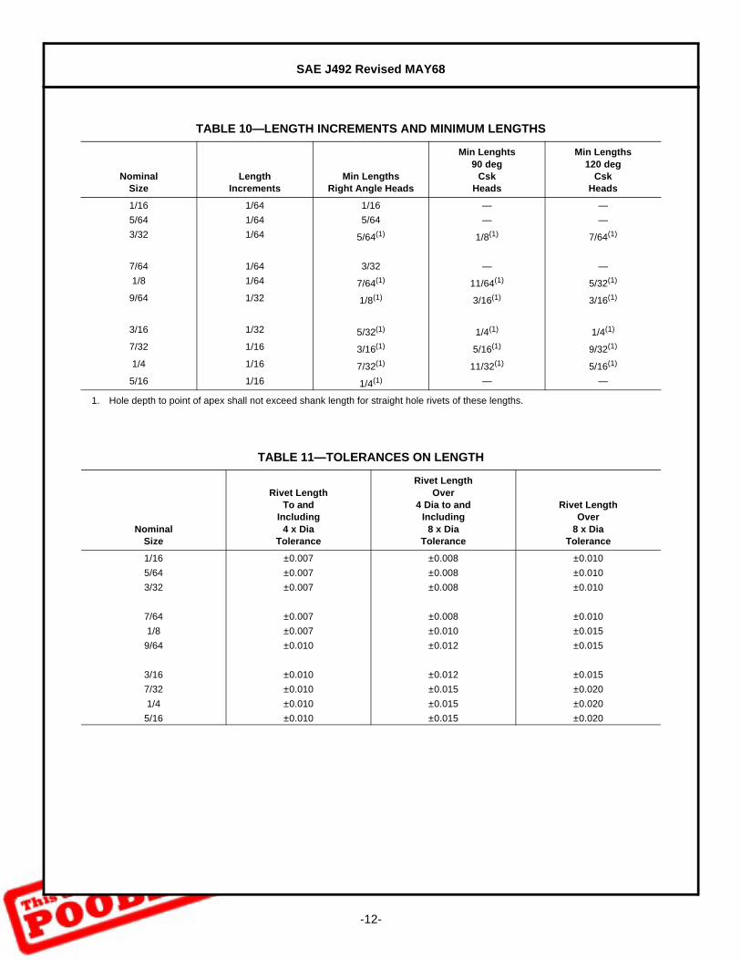
TABLE 10—LENGTH INCREMENTS AND MINIMUM LENGTHS
NominalSize
LengthIncrements
Min LengthsRight Angle Heads
Min Lenghts90 deg
CskHeads
Min Lengths120 deg
CskHeads
1/16 1/64 1/16 — —
5/64 1/64 5/64 — —
3/32 1/64 5/64(1)
1. Hole depth to point of apex shall not exceed shank length for straight hole rivets of these lengths.
1/8(1) 7/64(1)
7/64 1/64 3/32 — —
1/8 1/64 7/64(1) 11/64(1) 5/32(1)
9/64 1/32 1/8(1) 3/16(1) 3/16(1)
3/16 1/32 5/32(1) 1/4(1) 1/4(1)
7/32 1/16 3/16(1) 5/16(1) 9/32(1)
1/4 1/16 7/32(1) 11/32(1) 5/16(1)
5/16 1/16 1/4(1) — —
TABLE 11—TOLERANCES ON LENGTH
NominalSize
Rivet LengthTo and
Including4 x Dia
Tolerance
Rivet LengthOver
4 Dia to andIncluding
8 x DiaTolerance
Rivet LengthOver
8 x DiaTolerance
1/16 ±0.007 ±0.008 ±0.010
5/64 ±0.007 ±0.008 ±0.010
3/32 ±0.007 ±0.008 ±0.010
7/64 ±0.007 ±0.008 ±0.010
1/8 ±0.007 ±0.010 ±0.015
9/64 ±0.010 ±0.012 ±0.015
3/16 ±0.010 ±0.012 ±0.015
7/32 ±0.010 ±0.015 ±0.020
1/4 ±0.010 ±0.015 ±0.020
5/16 ±0.010 ±0.015 ±0.020
SAE J492 Revised MAY68
-13-
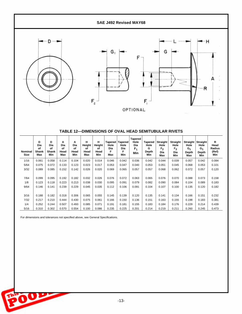
TABLE 12—DIMENSIONS OF OVAL HEAD SEMITUBULAR RIVETS
NominalSize
DDiaof
ShankMax
DDiaof
ShankMin
ADiaof
HeadMax
ADiaof
HeadMin
HHeight
of HeadMax
HHeight
of HeadMin
Tapered HoleDiaF
Max
Tapered HoleDiaF
Min
TaperedHoleDiaF1
Min
TaperedHole
GDepth
Min
StraightHoleF2DiaMax
StraightHoleF2DiaMin
StraightHoleG1
DepthMax
StraightHoleG1
DepthMin
RHead
Radius(Ref)Min
1/16 0.061 0.058 0.114 0.104 0.020 0.014 0.046 0.042 0.036 0.042 0.044 0.039 0.057 0.042 0.084
5/64 0.075 0.072 0.133 0.123 0.023 0.017 0.053 0.047 0.040 0.053 0.051 0.045 0.068 0.053 0.101
3/32 0.089 0.085 0.152 0.142 0.026 0.020 0.069 0.065 0.057 0.057 0.068 0.062 0.072 0.057 0.120
7/64 0.099 0.095 0.192 0.182 0.032 0.026 0.076 0.072 0.063 0.065 0.076 0.070 0.088 0.073 0.158
1/8 0.123 0.118 0.223 0.213 0.038 0.030 0.095 0.091 0.079 0.082 0.090 0.084 0.104 0.089 0.183
9/64 0.146 0.141 0.239 0.229 0.045 0.035 0.112 0.106 0.091 0.104 0.107 0.100 0.135 0.120 0.182
3/16 0.188 0.182 0.318 0.306 0.065 0.055 0.145 0.139 0.120 0.135 0.141 0.134 0.166 0.151 0.232
7/32 0.217 0.210 0.444 0.430 0.075 0.061 0.166 0.150 0.136 0.151 0.163 0.155 0.198 0.183 0.381
1/4 0.252 0.244 0.507 0.493 0.085 0.071 0.191 0.181 0.155 0.183 0.184 0.176 0.229 0.214 0.439
5/16 0.310 0.302 0.570 0.554 0.100 0.086 0.235 0.225 0.201 0.214 0.219 0.211 0.260 0.245 0.473
For dimensions and tolerances not specified above, see General Specifications.
SAE J492 Revised MAY68
-14-
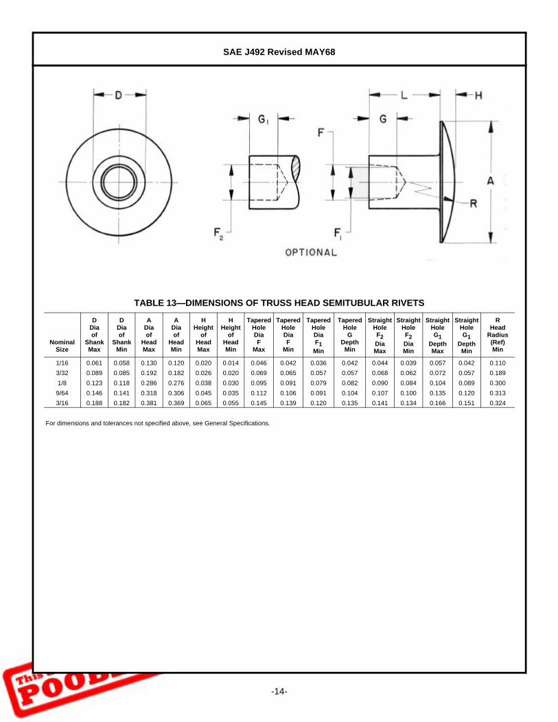
TABLE 13—DIMENSIONS OF TRUSS HEAD SEMITUBULAR RIVETS
NominalSize
DDiaof
ShankMax
DDiaof
ShankMin
ADiaof
HeadMax
ADiaof
HeadMin
HHeight
ofHeadMax
HHeight
ofHeadMin
Tapered HoleDiaF
Max
Tapered HoleDiaF
Min
TaperedHoleDiaF1
Min
TaperedHole
GDepth
Min
Straight HoleF2 DiaMax
StraightHoleF2DiaMin
Straight HoleG1
DepthMax
Straight HoleG1
DepthMin
RHead
Radius(Ref)Min
1/16 0.061 0.058 0.130 0.120 0.020 0.014 0.046 0.042 0.036 0.042 0.044 0.039 0.057 0.042 0.110
3/32 0.089 0.085 0.192 0.182 0.026 0.020 0.069 0.065 0.057 0.057 0.068 0.062 0.072 0.057 0.189
1/8 0.123 0.118 0.286 0.276 0.038 0.030 0.095 0.091 0.079 0.082 0.090 0.084 0.104 0.089 0.300
9/64 0.146 0.141 0.318 0.306 0.045 0.035 0.112 0.106 0.091 0.104 0.107 0.100 0.135 0.120 0.313
3/16 0.188 0.182 0.381 0.369 0.065 0.055 0.145 0.139 0.120 0.135 0.141 0.134 0.166 0.151 0.324
For dimensions and tolerances not specified above, see General Specifications.
SAE J492 Revised MAY68
-15-
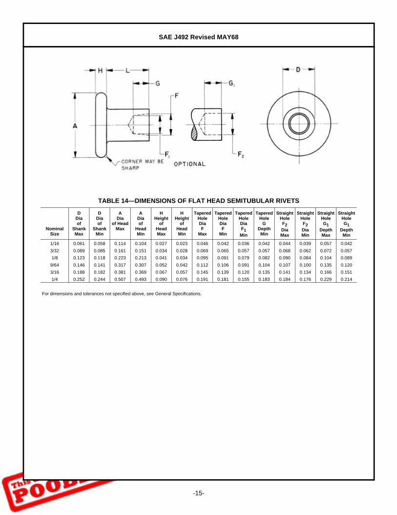
TABLE 14—DIMENSIONS OF FLAT HEAD SEMITUBULAR RIVETS
NominalSize
DDiaof
ShankMax
DDiaof
ShankMin
ADia
of HeadMax
ADiaof
HeadMin
HHeight
ofHeadMax
HHeight
ofHeadMin
Tapered HoleDiaF
Max
Tapered HoleDiaF
Min
Tapered HoleDiaF1
Min
Tapered Hole
GDepthMin
Straight HoleF2DiaMax
Straight HoleF2DiaMin
Straight HoleG1
DepthMax
Straight HoleG1
DepthMin
1/16 0.061 0.058 0.114 0.104 0.027 0.023 0.046 0.042 0.036 0.042 0.044 0.039 0.057 0.042
3/32 0.089 0.085 0.161 0.151 0.034 0.028 0.069 0.065 0.057 0.057 0.068 0.062 0.072 0.057
1/8 0.123 0.118 0.223 0.213 0.041 0.034 0.095 0.091 0.079 0.082 0.090 0.084 0.104 0.089
9/64 0.146 0.141 0.317 0.307 0.052 0.042 0.112 0.106 0.091 0.104 0.107 0.100 0.135 0.120
3/16 0.188 0.182 0.381 0.369 0.067 0.057 0.145 0.139 0.120 0.135 0.141 0.134 0.166 0.151
1/4 0.252 0.244 0.507 0.493 0.090 0.076 0.191 0.181 0.155 0.183 0.184 0.176 0.229 0.214
For dimensions and tolerances not specified above, see General Specifications.

SAE J492 Revised MAY68
-16-
TABLE 15—DIMENSIONS OF 90 DEGREE COUNTERSUNK HEAD SEMITUBULAR RIVETS
NominalSize
DDiaof
ShankMax
ADiaof
ShankMin
ADiaof
HeadMax
Sharp
ADiaof
HeadAbs
Sharp
HHeight
ofHeadRef(1)
1. Height of head, H, is given for reference purposes only. Variations in this dimension are controlled by diameters A and D and included angle of the head.For dimensions and tolerances not specified above, see General Specifications.
Tapered HoleDiaF
Max
Tapered HoleDiaF
Min
Tapered HoleDiaF1
Min
Tapered Hole
GDepthMin
Straight HoleF2DiaMax
Straight HoleF2DiaMin
Straight HoleG1
DepthMax
Straight HoleG1
DepthMin
3/32 0.089 0.085 0.176 0.163 0.045 0.069 0.065 0.057 0.057 0.068 0.062 0.072 0.057
1/8 0.123 0.118 0.235 0.217 0.057 0.095 0.091 0.079 0.082 0.090 0.084 0.104 0.089
9/64 0.146 0.141 0.270 0.250 0.060 0.112 0.106 0.091 0.104 0.107 0.100 0.135 0.120
3/16 0.188 0.182 0.351 0.326 0.083 0.145 0.139 0.120 0.135 0.141 0.134 0.166 0.151
7/32 0.217 0.210 0.413 0.384 0.100 0.166 0.158 0.136 0.151 0.163 0.155 0.198 0.183
1/4 0.252 0.244 0.469 0.437 0.112 0.191 0.181 0.155 0.183 0.184 0.176 0.229 0.214

SAE J492 Revised MAY68
-17-
TABLE 16—DIMENSIONS OF 120 DEGREE COUNTERSUNK HEAD SEMITUBULAR RIVETS
NominalSize
DDiaof
ShankMax
DDiaof
ShankMin
ADiaof
HeadMax
Sharp
ADiaof
HeadAbsMin
HHeight
ofHeadRef(1)
1. Height of head, H, is given for reference purposes only. Variations in this dimension are controlled by diameters A and D and inlcuded angle of the head.For dimensions and tolerances not specified above, see General Specifications.
Tapered HoleDiaF
Max
Tapered HoleDiaF
Min
Tapered HoleDiaF1
Min
Tapered Hole
GDepthMin
Straight HoleF2DiaMax
Straight HoleF2DiaMin
Straight HoleG1
DepthMax
Straight HoleG1
DepthMin
3/32 0.089 0.085 0.223 0.203 0.041 0.069 0.065 0.057 0.057 0.068 0.062 0.072 0.057
1/8 0.123 0.118 0.271 0.245 0.045 0.095 0.091 0.079 0.082 0.090 0.084 0.104 0.089
9/64 0.146 0.141 0.337 0.307 0.057 0.112 0.106 0.091 0.104 0.107 0.100 0.135 0.120
3/16 0.188 0.182 0.404 0.369 0.065 0.145 0.139 0.120 0.135 0.141 0.134 0.166 0.151
7/32 0.217 0.210 0.472 0.430 0.077 0.166 0.158 0.136 0.151 0.163 0.155 0.198 0.183
1/4 0.252 0.244 0.540 0.493 0.087 0.191 0.181 0.155 0.183 0.184 0.176 0.299 0.214
SAE J492 Revised MAY68
-18-
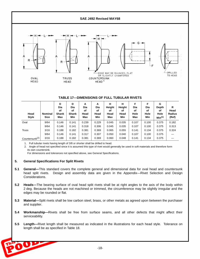
5. General Specifications For Split Rivets
5.1 General—This standard covers the complete general and dimensional data for oval head and countersunkhead split rivets. Design and assembly data are given in the Appendix—Rivet Selection and DesignConsiderations.
5.2 Heads—The bearing surface of oval head split rivets shall be at right angles to the axis of the body within2 deg. Because the heads are not machined or trimmed, the circumference may be slightly irregular and theedges may be rounded or flat.
5.3 Material—Split rivets shall be low carbon steel, brass, or other metals as agreed upon between the purchaserand supplier.
5.4 Workmanship—Rivets shall be free from surface seams, and all other defects that might affect theirserviceability.
5.5 Length—Rivet length shall be measured as indicated in the illustrations for each head style. Tolerance onlength shall be as specified in Table 18.
TABLE 17—DIMENSIONS OF FULL TUBULAR RIVETS
HeadStyle
NominalSize
DDiaof
ShankMax
DDiaof
ShankMin
ADiaof
HeadMax
ADiaof
HeadMin
HHeight
ofHeadMax
HHeight
ofHeadMin
FDiaof
HoleMax
FDiaof
HoleMin
GDepth
ofHole
Min(1)
1. Full tubular rivets having length of 3/8 or shorter shall be drilled to head.
RHead
Radius(Ref)
Oval 9/64 0.146 0.141 0.239 0.229 0.045 0.035 0.107 0.100 0.375 0.182
9/64 0.146 0.141 0.318 0.306 0.045 0.035 0.107 0.100 0.375 0.313
Truss 3/16 0.188 0.182 0.381 0.369 0.065 0.055 0.141 0.134 0.375 0.324
9/64 0.146 0.141 0.317 0.307 0.050 0.040 0.107 0.100 0.375 —
Countersunk(2)
2. Angle of head not specified since it is assumed this type of rivet would generally be used in soft materials and therefore form its own countersink.For dimensions and tolerances not specified above, see General Specifications.
3/16 0.188 0.182 0.381 0.369 0.060 0.048 0.141 0.134 0.375 —
SAE J492 Revised MAY68
-19-
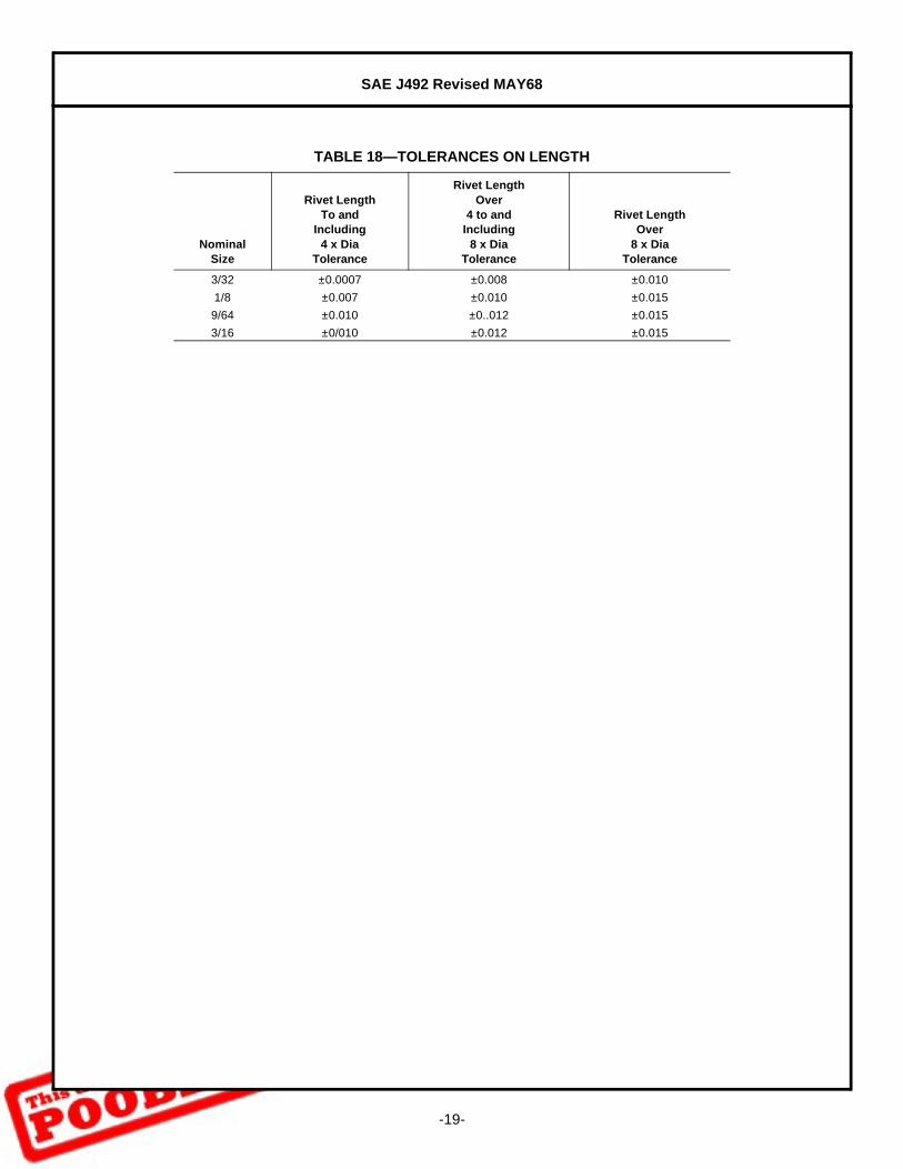
TABLE 18—TOLERANCES ON LENGTH
Nominal Size
Rivet LengthTo and
Including4 x Dia
Tolerance
Rivet LengthOver
4 to andIncluding
8 x DiaTolerance
Rivet LengthOver
8 x DiaTolerance
3/32 ±0.0007 ±0.008 ±0.010
1/8 ±0.007 ±0.010 ±0.015
9/64 ±0.010 ±0..012 ±0.015
3/16 ±0/010 ±0.012 ±0.015

SAE J492 Revised MAY68
-20-
TABLE 19—DIMENSIONS OF OVAL HEAD SPLIT RIVETS
Nominal Size
DDiaof
ShankMax
DDiaof
ShankMin
ADiaof
HeadMax
ADiaof
HeadMin
HHeight
ofHeadMax
HHeight
ofHeadMin
ERadius
ofFilletMax
RRadius
ofHeadRef
L(1)
Lengthof
Rivet
1. Lengths over those tabulated shall be in increments of 1/16 in.For dimensions and tolerances not specified above, see General Specifications.
FDepth
ofSlot
±0.015
Widthof
SlotG
±0.005
Widthof
SlotJ
±0.005
3/16 0.156 0.030 0.037
1/4 0.219 0.030 0.039
3/32 0.092 0.086 0.151 0.141 0.027 0.019 0.010 0.130 5/16 0.250 0.030 0.039
3/8 and over 0.312 0.030 0.039
3/16 0.156 0.040 0.047
1/4 0.219 0.040 0.052
1/8 0.122 0.114 0.223 0.213 0.037 0.027 0.014 0.210 5/16 0.266 0.040 0.057
3/8 and over 0.312 0.040 0.057
3/16 0.156 0.050 0.060
1/4 0.219 0.050 0.073
9/64 0.152 0.144 0.317 0.307 0.049 0.037 0.018 0.304 5/16 0.281 0.050 0.078
3/8 0.328 0.050 0.081
7/16 0.344 0.050 0.083
1/2 and over 0.391 0.052 0.077
1/4 0.219 0.065 0.120
5/16 0.281 0.065 0.125
3/16 0.195 0.185 0.350 0.338 0.064 0.050 0.022 0.300 3/8 0.312 0.065 0.127
7/16 0.375 0.065 0.130
1/2 and over 0.437 0.068 0.133

SAE J492 Revised MAY68
-21-
TABLE 20—DIMENSIONS OF COUNTERSUNK HEAD SPLIT RIVETS
NominalSize
DDiaof
ShankMax
DDiaof
ShankMin
ADiaof
HeadMax
ADiaof
HeadMin
HHeight
ofHeadMax
HHeight
ofHeadMin
LLength
ofRivet
FDepth
ofSlot
±0.016
Widthof
SlotG
±0.005
Widthof
SlotJ
±0.005
1/4 0.156 0.040 0.047
1/8 0.122 0.114 0.223 0.213 0.036 0.026 5/16 0.219 0.040 0.052
3/8 0.281 0.040 0.057
7/16 and over 0.312 0.040 0.057
1/4 0.156 0.050 0.060
5/16 0.219 0.050 0.073
3/8 0.281 0.050 0.078
0.317 0.307 0.053 0.043 7/16 0.328 0.050 0.081
1/2 0.344 0.050 0.083
9/64 0.152 0.144 9/16 and over 0.391 0.052 0.077
1/4 0.156 0.050 0.060
5/16 0.219 0.050 0.073
0.380 0.370 0.062 0.052 3/8 0.281 0.050 0.078
7/16 0.328 0.050 0.081
1/2 0.344 0.050 0.083
9/16 and over 0.391 0.052 0.077
5/16 0.219 0.065 0.120
3/8 0.281 0.065 0.125
3/16 0.195 0.185 0.443 0.431 0.061 0.051 7/16 0.312 0.065 0.127
1/2 0.375 0.065 0.130
9/16 and over 0.437 0.068 0.133

SAE J492 Revised MAY68
-22-
6. General Specifications For Rivet Caps
6.1 General—This standard covers the complete general and dimensional data for rivet caps used with full tubularand split rivets where appearance is a consideration.
6.2 Materials—Rivet caps shall be brass or steel, standard with manufacturer.
6.3 Workmanship—Rivet caps shall be free from all defects that might affect their serviceability.
7. General Specifications For Eyelets
7.1 General—This standard covers the complete general and dimensional data for rolled flange eyelets. Designand assembly data are given in the Appendix—Rivet Selection and Design Considerations.
7.2 Flanges—Flanges of eyelets shall not be eccentric with the shank by more than 0.0075 in.
7.3 Material—Eyelets shall be brass, steel, or aluminum, standard with manufacturer.
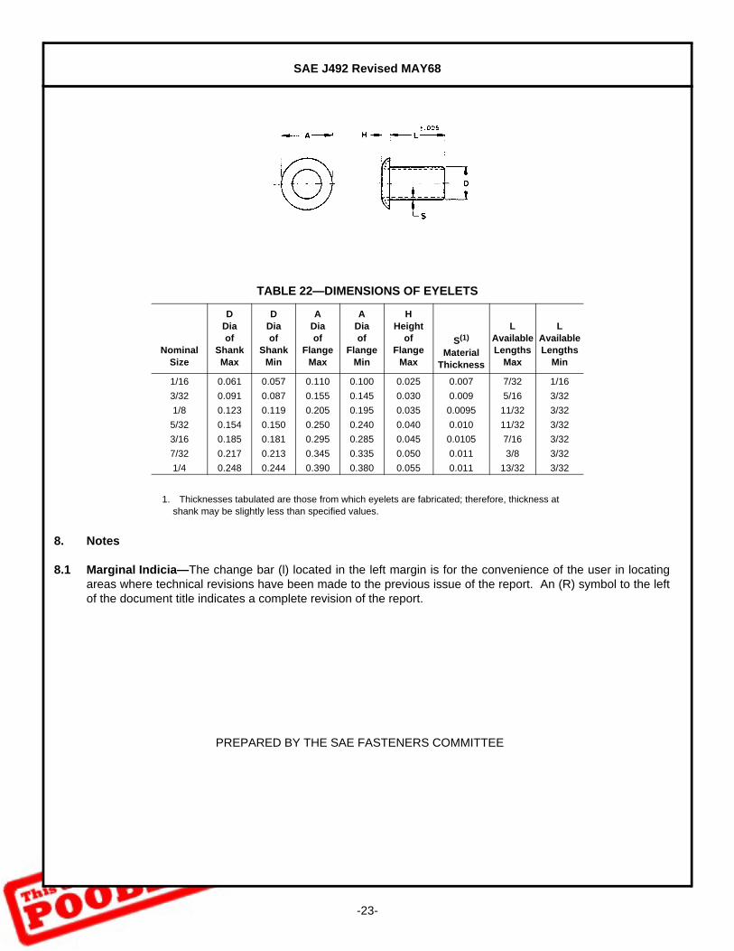
7.4 Length—Length of eyelets shall be measured as indicated in the illustration. They are available in lengthincrements of 1/32 in. between the limits specified in Table 22.
7.5 Workmanship—Eyelet end irregularities shall not be such that usability of the eyelet is impaired. Eyelets shallbe free from surface seams, splits, and all other defects that might affect their serviceability.
TABLE 21—DIMENSIONS OF RIVET CAPS
Style
DDia
of HoleMax
DDia
of HoleMin
AOutside
DiaMax
AOutside
DiaMin
HHeight
Max
HHeight
Min
0.233 0.203 0.288 0.258 0.098 0.068
1(1)
1. Style 1 rivet caps are designed for use with split rivets.
0.233 0.203 0.311 0.299 0.098 0.068
0.233 0.203 0.358 0.346 0.098 0.068
2(2)
2. Style 2 rivet cpas are designed for use with full tubular rivets.
0.233 0.203 0.350 0.320 0.098 0.068
0.281 0.251 0.442 0.412 0.129 0.099
SAE J492 Revised MAY68
-23-
8. Notes
8.1 Marginal Indicia—The change bar (l) located in the left margin is for the convenience of the user in locatingareas where technical revisions have been made to the previous issue of the report. An (R) symbol to the leftof the document title indicates a complete revision of the report.
PREPARED BY THE SAE FASTENERS COMMITTEE
TABLE 22—DIMENSIONS OF EYELETS
NominalSize
DDiaof
ShankMax
DDiaof
ShankMin
ADiaof
FlangeMax
ADiaof
FlangeMin
HHeight
ofFlange
Max
S(1)
MaterialThickness
1. Thicknesses tabulated are those from which eyelets are fabricated; therefore, thickness at shank may be slightly less than specified values.
LAvailableLengths
Max
LAvailableLengths
Min
1/16 0.061 0.057 0.110 0.100 0.025 0.007 7/32 1/16
3/32 0.091 0.087 0.155 0.145 0.030 0.009 5/16 3/32
1/8 0.123 0.119 0.205 0.195 0.035 0.0095 11/32 3/32
5/32 0.154 0.150 0.250 0.240 0.040 0.010 11/32 3/32
3/16 0.185 0.181 0.295 0.285 0.045 0.0105 7/16 3/32
7/32 0.217 0.213 0.345 0.335 0.050 0.011 3/8 3/32
1/4 0.248 0.244 0.390 0.380 0.055 0.011 13/32 3/32
SAE J492 Revised MAY68
-24-
APPENDIX A
RIVET SELECTION AND DESIGN CONSIDERATIONS
A.1 General—This appendix is a guide intended to aid the user in the proper selection and application of rivets asa fastening means. It consists of general information on the advantages of riveting, various methods ofriveting, selection of rivets and design considerations.
A.2 Advantages of Riveting—Riveting as a means of fastening is popular because of its simplicity, dependability,and low cost. Where the parts to be assembled do not normally need to be disassembled and, in the case oftubular, semi-tubular and split rivets, the tensile and fatigue strength of the joinings made are not critical,riveting has many advantages. Some of the more outstanding of these are:
1. Metallic rivets are almost universally made by cold heading in high speed headers, and this makes arivet a very economical fastener.
2. Investment in assembly equipment is low.3. Maintenance costs of assembly equipment are low.4. Rate of assembly is high and due to its simplicity, riveting lends itself to automation.5. A minimum of skill is required to perform the operation.6. Metallic or nonmetallic materials, or combinations thereof may be joined.7. Rivets can be produced in a great variety of metals, ranging from low carbon steel to precious metals
such as silver or gold.8. Rivets may be used, not only as fasteners, but as functional components, such as pivots, electrical
contacts, spacers, or supports.9. Riveting normally requires no supplementary parts such as plain washers, lock washers, nuts, or
safety wiring, nor are additional operations required such as assembly of nuts or locking devices as inthe case of threaded fasteners.
10. Except for tubular, semitubular and split rivets, the rivet, when driven, usually fills the hole and preventsshifting of the parts joined.
A.3 Methods of Riveting—Riveting operations are performed by a number of methods, some of which areapplicable only to particular types of rivets. The most commonly used methods are as follows:
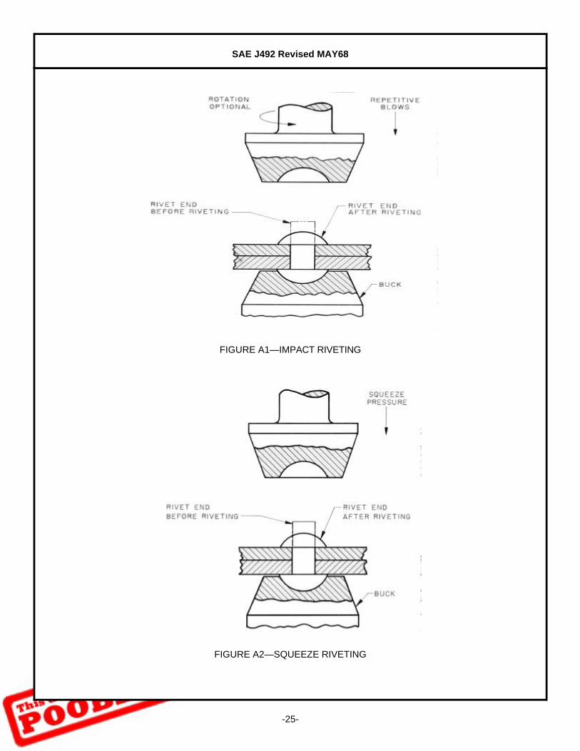
A.3.1 Impact—This method employs a header die which strikes repetitive blows thus forming a head while thepreformed end of the rivet is backed up with a tool called a buck or bucking bar. The header die may also berotated while striking the repetitive blows. In machine riveting the buck is usually a part of the holding fixture.The method is applicable to solid rivets driven either hot or cold. Hot riveting is usually confined to largerivets used for structural purposes, while cold riveting is the method generally used for industrial applicationson manufactured products. During the riveting operation the rivet material is displaced outward anddownward into contact with the sides of the hole in which it is being assembled. The remainder of thematerial at rivet end forms the head. Upsetting of the shank can be controlled by using the proper impactforce. See Figure A1.
A.3.2 Squeeze—As its name implies, this method consists of applying steady pressure with a formed header diewhile the preformed end of rivet is backed up with a buck which may be made a part of the holding fixture.This method is applicable to solid rivets driven hot or cold. As in the case of impact riveting, the rivet materialis displaced outward and downward into contact with the sides of the hole in which it is being assembled.The remainder of the material forms the head. See Figure A2.
SAE J492 Revised MAY68
-25-
FIGURE A1—IMPACT RIVETING
FIGURE A2—SQUEEZE RIVETING
SAE J492 Revised MAY68
-26-
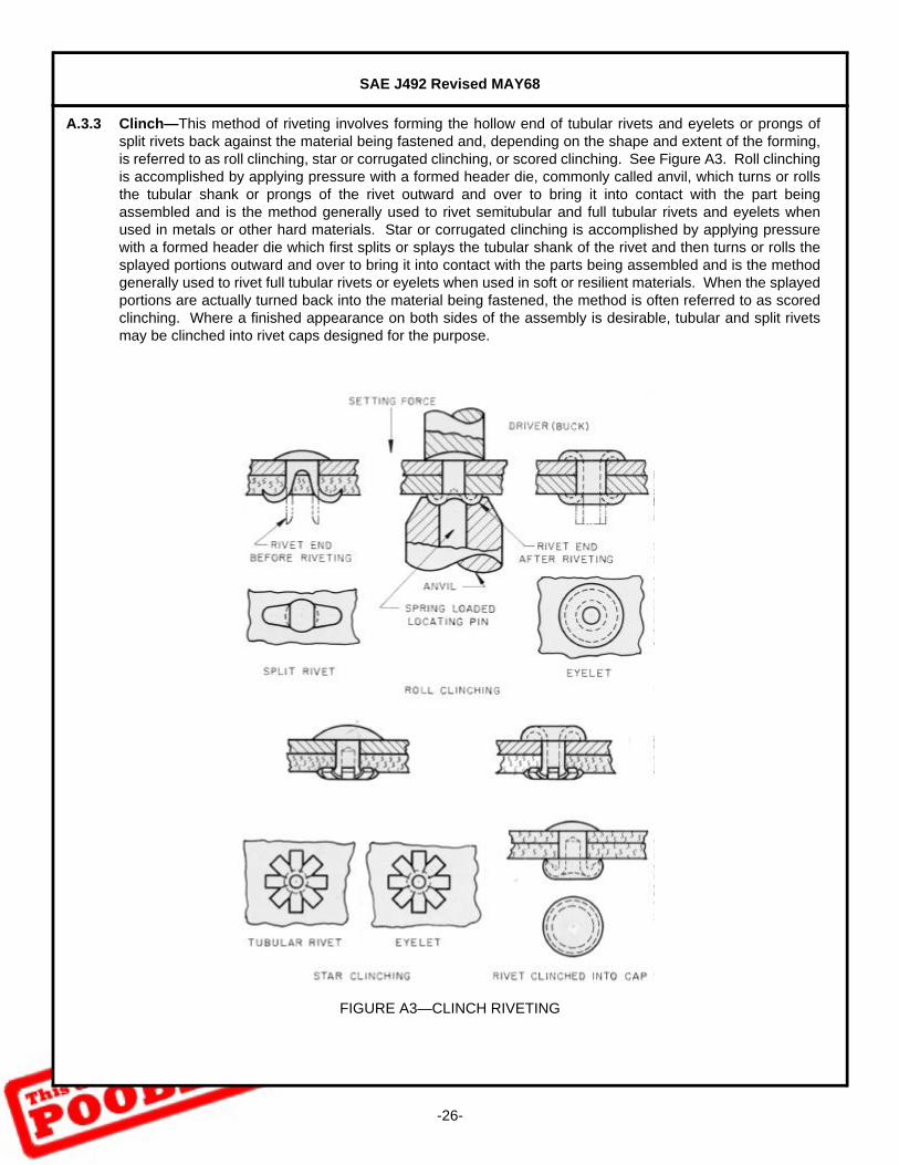
A.3.3 Clinch—This method of riveting involves forming the hollow end of tubular rivets and eyelets or prongs ofsplit rivets back against the material being fastened and, depending on the shape and extent of the forming,is referred to as roll clinching, star or corrugated clinching, or scored clinching. See Figure A3. Roll clinchingis accomplished by applying pressure with a formed header die, commonly called anvil, which turns or rollsthe tubular shank or prongs of the rivet outward and over to bring it into contact with the part beingassembled and is the method generally used to rivet semitubular and full tubular rivets and eyelets whenused in metals or other hard materials. Star or corrugated clinching is accomplished by applying pressurewith a formed header die which first splits or splays the tubular shank of the rivet and then turns or rolls thesplayed portions outward and over to bring it into contact with the parts being assembled and is the methodgenerally used to rivet full tubular rivets or eyelets when used in soft or resilient materials. When the splayedportions are actually turned back into the material being fastened, the method is often referred to as scoredclinching. Where a finished appearance on both sides of the assembly is desirable, tubular and split rivetsmay be clinched into rivet caps designed for the purpose.
FIGURE A3—CLINCH RIVETING
SAE J492 Revised MAY68
-27-
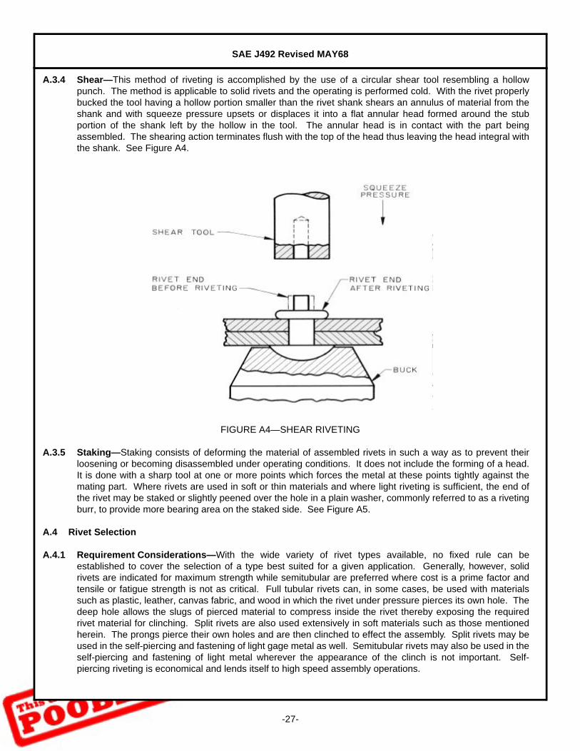
A.3.4 Shear—This method of riveting is accomplished by the use of a circular shear tool resembling a hollowpunch. The method is applicable to solid rivets and the operating is performed cold. With the rivet properlybucked the tool having a hollow portion smaller than the rivet shank shears an annulus of material from theshank and with squeeze pressure upsets or displaces it into a flat annular head formed around the stubportion of the shank left by the hollow in the tool. The annular head is in contact with the part beingassembled. The shearing action terminates flush with the top of the head thus leaving the head integral withthe shank. See Figure A4.
FIGURE A4—SHEAR RIVETING
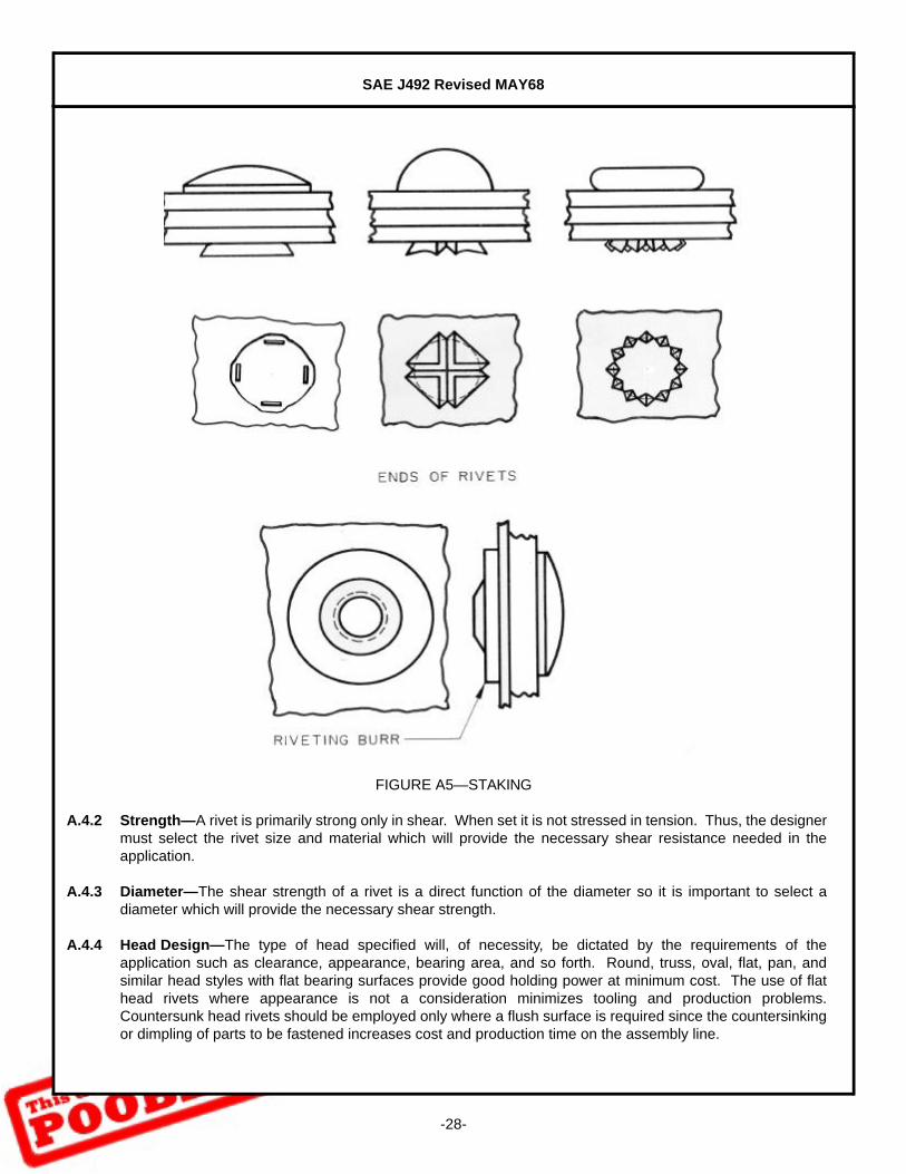
A.3.5 Staking—Staking consists of deforming the material of assembled rivets in such a way as to prevent theirloosening or becoming disassembled under operating conditions. It does not include the forming of a head.It is done with a sharp tool at one or more points which forces the metal at these points tightly against themating part. Where rivets are used in soft or thin materials and where light riveting is sufficient, the end ofthe rivet may be staked or slightly peened over the hole in a plain washer, commonly referred to as a rivetingburr, to provide more bearing area on the staked side. See Figure A5.
A.4 Rivet Selection
A.4.1 Requirement Considerations—With the wide variety of rivet types available, no fixed rule can beestablished to cover the selection of a type best suited for a given application. Generally, however, solidrivets are indicated for maximum strength while semitubular are preferred where cost is a prime factor andtensile or fatigue strength is not as critical. Full tubular rivets can, in some cases, be used with materialssuch as plastic, leather, canvas fabric, and wood in which the rivet under pressure pierces its own hole. Thedeep hole allows the slugs of pierced material to compress inside the rivet thereby exposing the requiredrivet material for clinching. Split rivets are also used extensively in soft materials such as those mentionedherein. The prongs pierce their own holes and are then clinched to effect the assembly. Split rivets may beused in the self-piercing and fastening of light gage metal as well. Semitubular rivets may also be used in theself-piercing and fastening of light metal wherever the appearance of the clinch is not important. Self-piercing riveting is economical and lends itself to high speed assembly operations.
SAE J492 Revised MAY68
-28-
FIGURE A5—STAKING
A.4.2 Strength—A rivet is primarily strong only in shear. When set it is not stressed in tension. Thus, the designermust select the rivet size and material which will provide the necessary shear resistance needed in theapplication.
A.4.3 Diameter—The shear strength of a rivet is a direct function of the diameter so it is important to select adiameter which will provide the necessary shear strength.
A.4.4 Head Design—The type of head specified will, of necessity, be dictated by the requirements of theapplication such as clearance, appearance, bearing area, and so forth. Round, truss, oval, flat, pan, andsimilar head styles with flat bearing surfaces provide good holding power at minimum cost. The use of flathead rivets where appearance is not a consideration minimizes tooling and production problems.Countersunk head rivets should be employed only where a flush surface is required since the countersinkingor dimpling of parts to be fastened increases cost and production time on the assembly line.
SAE J492 Revised MAY68
-29-
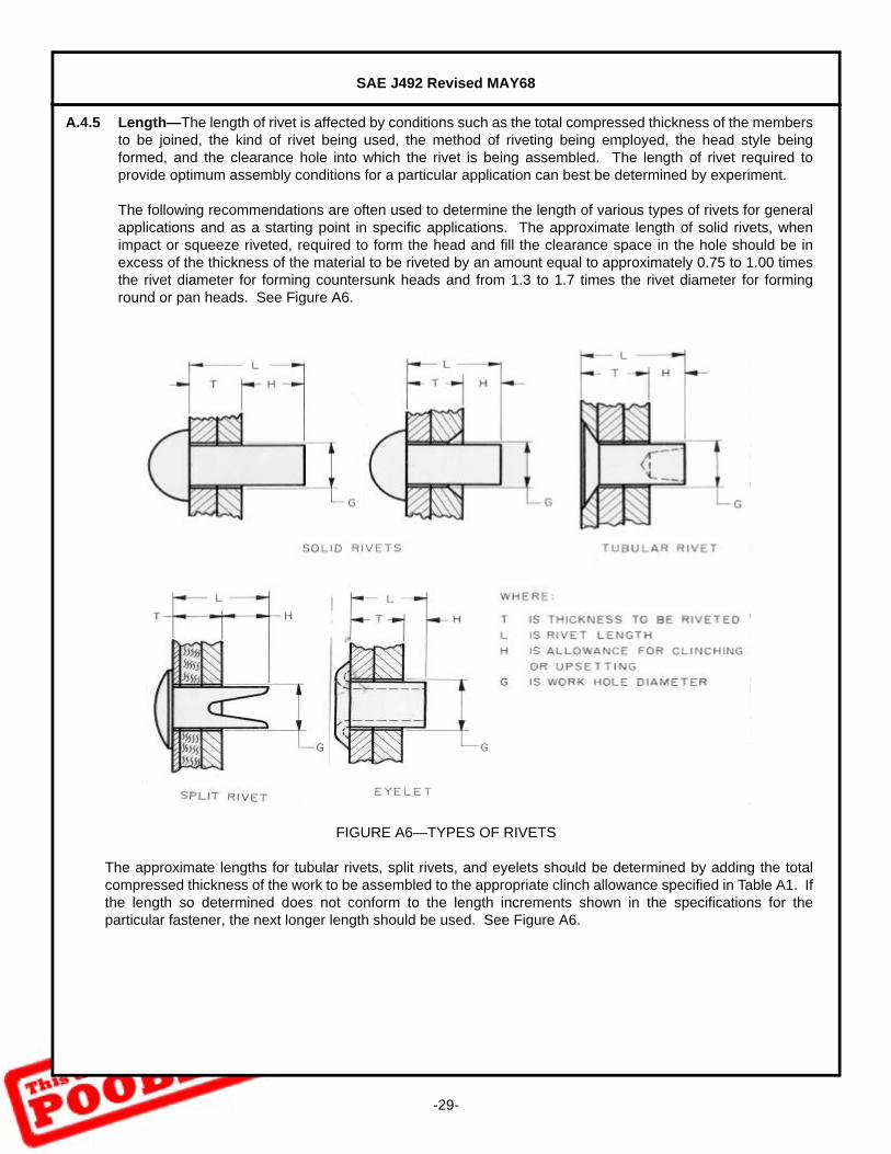
A.4.5 Length—The length of rivet is affected by conditions such as the total compressed thickness of the membersto be joined, the kind of rivet being used, the method of riveting being employed, the head style beingformed, and the clearance hole into which the rivet is being assembled. The length of rivet required toprovide optimum assembly conditions for a particular application can best be determined by experiment.
The following recommendations are often used to determine the length of various types of rivets for generalapplications and as a starting point in specific applications. The approximate length of solid rivets, whenimpact or squeeze riveted, required to form the head and fill the clearance space in the hole should be inexcess of the thickness of the material to be riveted by an amount equal to approximately 0.75 to 1.00 timesthe rivet diameter for forming countersunk heads and from 1.3 to 1.7 times the rivet diameter for forminground or pan heads. See Figure A6.
FIGURE A6—TYPES OF RIVETS
The approximate lengths for tubular rivets, split rivets, and eyelets should be determined by adding the totalcompressed thickness of the work to be assembled to the appropriate clinch allowance specified in Table A1. Ifthe length so determined does not conform to the length increments shown in the specifications for theparticular fastener, the next longer length should be used. See Figure A6.

SAE J492 Revised MAY68
-30-
A.5 Design Considerations—After the design of rivet to be used has been determined which includes diameter,type of head, material, and other factors, the designer must then establish other related features of the designof the assembly.
A.5.1 Spacing—Where more than one rivet is indicated, the spacing between rivets must be such that there issufficient room for the driving tools. Also a minimum pitch of 3 times the rivet diameter should be provided.For thin sheets it is recommended that the pitch be not greater than 24 times the thickness of the sheet. Forfunctional strength consideration the strength afforded by the portion of metal between rivet holes should bedetermined and compared with the shear and bearing strength of the rivets.
A.5.2 Edge Distance—Failure of the metal between the rivet hole and the edge of the sheet, where solid rivets areused, can be prevented by maintaining an edge distance of 1½ times the hole diameter for hot driven rivetsand 2 times the hole diameter for cold driven rivets.
Clinching of tubular rivets exerts little radial force on the sides of the hole compared to the driving of solidrivets. The edge distance, where tubular rivets are used, can, therefore, be less than the values givenherein. It can, in most applications, be dictated by the strength of the material and the load to be applied onthe riveted joint. The small amount of radial force need be considered only where fastening very brittlematerials such as ceramics and some plastics.
A.5.3 Accessibility—When using standard rivets, it is necessary to have both the preformed and driven headends of the rivet accessible so that both the forming die and the buck may be properly used. Sufficient spaceshould be provided to permit the use of power or manually operated rivet sets and bucks.
TABLE A1—RECOMMENDED CINCH ALLOWANCES FOR TUBULAR AND SPLIT RIVETS AND EYELETS
NominalSize
Clinch AllowancesSemitubular
Rivets(1)
1. For rolled cinch.
Clinch Allowances
FullTubular
Rivets(2)
2. For star or corrugated clinch, where roll clinch is desired, use semitubular values.
Clinch Allowances
SplitRivets
Clinch Allowances
Eyelets(1)
1/16 0.034 — — 0.043
5/64 0.041 — — —
3/32 0.048 — 0.078 0.048
7/64 0.059 — — —
1/8 0.074 — 0.094 0.048
9/64 0.088 0.125 0.0125 —
5/32 — — — 0.053
3/16 0.122 0.188 0.141 0.053
7/32 0.141 — — 0.058
1/4 0.162 — — 0.058
5/16 0.202 — — —
SAE J492 Revised MAY68
-31-
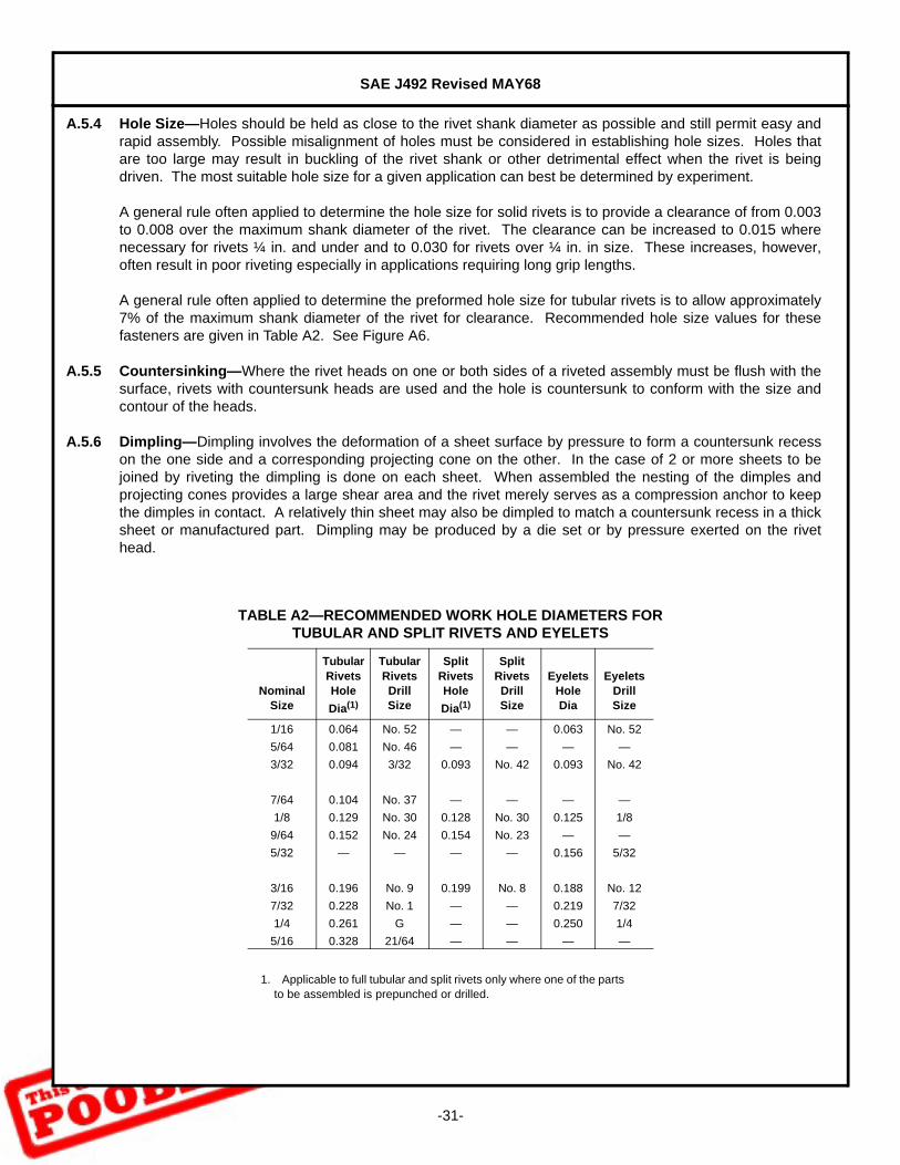
A.5.4 Hole Size—Holes should be held as close to the rivet shank diameter as possible and still permit easy andrapid assembly. Possible misalignment of holes must be considered in establishing hole sizes. Holes thatare too large may result in buckling of the rivet shank or other detrimental effect when the rivet is beingdriven. The most suitable hole size for a given application can best be determined by experiment.
A general rule often applied to determine the hole size for solid rivets is to provide a clearance of from 0.003to 0.008 over the maximum shank diameter of the rivet. The clearance can be increased to 0.015 wherenecessary for rivets ¼ in. and under and to 0.030 for rivets over ¼ in. in size. These increases, however,often result in poor riveting especially in applications requiring long grip lengths.
A general rule often applied to determine the preformed hole size for tubular rivets is to allow approximately7% of the maximum shank diameter of the rivet for clearance. Recommended hole size values for thesefasteners are given in Table A2. See Figure A6.
A.5.5 Countersinking—Where the rivet heads on one or both sides of a riveted assembly must be flush with thesurface, rivets with countersunk heads are used and the hole is countersunk to conform with the size andcontour of the heads.
A.5.6 Dimpling—Dimpling involves the deformation of a sheet surface by pressure to form a countersunk recesson the one side and a corresponding projecting cone on the other. In the case of 2 or more sheets to bejoined by riveting the dimpling is done on each sheet. When assembled the nesting of the dimples andprojecting cones provides a large shear area and the rivet merely serves as a compression anchor to keepthe dimples in contact. A relatively thin sheet may also be dimpled to match a countersunk recess in a thicksheet or manufactured part. Dimpling may be produced by a die set or by pressure exerted on the rivethead.
TABLE A2—RECOMMENDED WORK HOLE DIAMETERS FOR TUBULAR AND SPLIT RIVETS AND EYELETS
NominalSize
TubularRivetsHole
Dia(1)
1. Applicable to full tubular and split rivets only where one of the parts to be assembled is prepunched or drilled.
TubularRivetsDrillSize
SplitRivetsHole
Dia(1)
SplitRivetsDrillSize
EyeletsHoleDia
EyeletsDrillSize
1/16 0.064 No. 52 — — 0.063 No. 52
5/64 0.081 No. 46 — — — —
3/32 0.094 3/32 0.093 No. 42 0.093 No. 42
7/64 0.104 No. 37 — — — —
1/8 0.129 No. 30 0.128 No. 30 0.125 1/8
9/64 0.152 No. 24 0.154 No. 23 — —
5/32 — — — — 0.156 5/32
3/16 0.196 No. 9 0.199 No. 8 0.188 No. 12
7/32 0.228 No. 1 — — 0.219 7/32
1/4 0.261 G — — 0.250 1/4
5/16 0.328 21/64 — — — —
SAE J492 Revised MAY68
Rationale—Not applicable.
Relationship of SAE Standard to ISO Standard—Not applicable.
Application—This small solid rivet standard covers the complete general and dimensional data for flat head,pan head, button head, truss head, countersunk head, copper’s, tinner’s and belt rivets. Design andassembly data are given in the Appendix—River Selection and Design Considerations.
The inclusion of dimensional data in this standard is not intended to imply that all of the productsdescribed are stock production sizes. Consumers are requested to consult with manufacturersconcerning stock production sizes.
This tubular rivet standard covers the complete general and dimensional data for oval head, truss head,flat head, 90- and 120-deg countersunk head semitubular rivets and oval head, truss head andcountersunk head full tubular rivets. Design and assembly data are given in the Appendix—RivetSelection and Design Considerations.
The inclusion of dimensional data in this standard is not intended to imply that all of the productsdescribed are stock production sizes. Consumers are requested to consult with manufacturersconcerning stock production sizes.
This standard covers the complete general and dimensional data for oval head and countersunk headsplit rivets. Design and assembly data are given in the Appendix—Rivet Selection and DesignConsiderations.
This standard covers the complete general and dimensional data for rivet caps used with full tubular andsplit rivets where appearance is a consideration.
This standard covers the complete general and dimensional data for rolled flange eyelets. Design andassembly data are given in the Appendix—Rivet Selection and Design Considerations.
Reference Section—There are no referenced publications specified herein.
Developed by the SAE Fasteners Committee