Embed Size (px)
Citation preview
National Institute Of Technology Rourkela
May 2014 A Thesis submitted in partial fulfillment of the requirements for the degree of
bachelor of technology in
Electronics and Communication Engineering
VEHICLE TRACKING AND ACCIDENT ALERT SYSTEM.
Submitted by: KOMMINENI RAKESH (ROLL NO :110EC0220) Under guidance of: MUNSHI NURUL ISLAM
National Institute Of Technology
Department Of Electronics and Communication Engineering
CERTIFICATE
This is to certify that thesis report entitled VEHICLE TRACKING AND ACCIDENT
ALERT SYSTEM submitted by Kommineni Rakesh (110EC0220) of Electronics and
Communication during May 2014 at National Institute of Technology, Rourkela is
an authentic work performed by him under my supervision and guidance.
To the best of my knowledge matter embodied in the thesis is not submitted to
any other Institute/University for the award of any Degree or Diploma.
Prof. Munshi Nurul Islam
Dept. of Electronics and Communication Engineering
National Institute of Technology, Rourkela

National Institute Of Technology
Department Of Electronics and Communication Engineering
ACKNOWLEDGEMENT
First of all, I would like to thank Prof. MUNSHI NURUL ISLAM, Dept. of Electronics
and Communication Engineering, National Institute of Technology, Rourkela, my
guide, for his encouragement, guidance and cooperation to carry out this project,
and for giving me an opportunity to work on this project and providing me with a
great environment to carry our work in ease.
I also appreciate Prof. S.K.Behera, Prof. S Deshmukh, Prof. M Okhade, Prof. AK
Sahoo, Prof. AK Swain, Prof. S.M. Hiremath and other staff members for the
invaluable feedback and comments that helped me improving my work.
I am also thankful to Research Scholars and M. Tech. students for their co-
operation during use of laboratories and to all my friends who have directly or
indirectly helped me with the thesis and project.
Kommineni Rakesh
(110EC0220)
Dept. of Electronics and Communication Engineering
National Institute of Technology, Rourkela
ABSTRACT
Initially the GPS continuously takes input data from the satellite and stores the latitude and
longitude values in AT89s52 microcontroller's buffer. If we have to track the vehicle, we need to
send a message to GSM device, by which it gets activated. It also gets activated by detecting accident
on the shock sensor connected to vehicle. Parallely deactivates GPS with the help of relay .Once
GSM gets activated it takes the last received latitude and longitude positions values from the buffer
and sends a message to the particular number or laptop which is predefined in the program. Once
message has been sent to the predefined device the GSM gets deactivated and GPS gets activated.
List of figures
Figure 1 block diagram .................................................................................................................................... 11
Figure 2 overview of the system .................................................................................................................... 12
Figure 3 internal circuit diagram .................................................................................................................... 13
Figure 4 pin diagram of microcontroller AT89S52 .................................................................................... 15
Figure 5 GPS modem ...................................................................................................................................... 16
Figure 6 GSM modem .................................................................................................................................... 17
Figure 7 shock sensor ...................................................................................................................................... 18
Figure 8 Shock sensors position on vehicle ................................................................................................. 19
Figure 9 LCD interfacing with AT89S52 ..................................................................................................... 20
Figure 10 LCD display .................................................................................................................................... 20
Figure 11 output displayed on lcd ................................................................................................................. 33
Contents
ABSTRACT ................................................................................................................................................................... 6
LIST OF FIGURES ................................................................................................................................. 7
1. INTRODUCTION ................................................................................................................................................. 9
1.1 VEHICLE TRACKING FEATURES ..................................................................................................................... 9
1.2 ACCIDENT ALERT SYSTEM FEATURES ........................................................................................................ 10
1.3 USAGE OF TRACKING IN INDIA. ................................................................................................................... 10
2. BLOCK DIAGRAM .............................................................................................................................................. 11
2.1 CONCEPT AND OVERVIEW ........................................................................................................................... 12
2.2 INTERNAL CIRCUIT DIAGRAM ..................................................................................................................... 13
3. HARDWARE .......................................................................................................................................................... 14
3.1 MICROCONTROLLER ...................................................................................................................................... 15
3.2 GPS ................................................................................................................................................................... 16
3.3 GSM .................................................................................................................................................................. 17
3.4 SHOCK SENSOR .............................................................................................................................................. 18
3.4.1 SHOCK SENSOR INTEGRATION ................................................................................................................... 19
3.5 LIQUID CRYSTAL DISPLAY ............................................................................................................................ 19
4. VEHICLE TRACKING SYSTEM WORKING .......................................................................................................... 21
4.1 ACCIDENT ALERT SYSTEM WORKING ........................................................................................................ 21
5.CODE WRITTEN TO THE PROCESSOR ............................................................................................. 22
6. RESULTS .................................................................................................................................................................... 33
7. APPLICATIONS ......................................................................................................................................................... 34
8. CONCLUSION ........................................................................................................................................................... 35
9. BIBLIOGRAPHY ....................................................................................................................................................... 36
1. INTRODUCTION
Vehicle tracking system main aim is to give Security to all vehicles. Accident alert system main aim is
to rescuing people in accidents. This is improved security systems for vehicles. The latest like GPS
are highly useful now a days, this system enables the owner to observe and track his vehicle and find
out vehicle movement and its past activities of vehicle.
This new technology, popularly called vehicle Tracking Systems which created many wonders in the
security of the vehicle. This hardware is fitted on to the vehicle in such a manner that it is not visible
to anyone who is inside or outside of the vehicle. Thus it is used as a covert unit which continuously
or by any interrupt to the system, sends the location data to the monitoring unit.
When the vehicle is stolen, the location data from tracking system can be used to find the location
and can be informed to police for further action. Some Vehicle tracking System can even detect
unauthorized movements of the vehicle and then alert the owner. This gives an edge over other
pieces of technology for the same purpose.
This accident alert system in it detects the accident and the location of the accident occurred and
sends GPS coordinates to the specified mobile, computer etc.
1.1 Vehicle Tracking Features
It is mainly benefit for the companies which are based on transport system. Since it can show the
position of all vehicles in real time, so that they can create the expected data accordingly. These
tracking system can store the whole data where the vehicle had gone, where did it stop, how much
time it take at every stop and can create whole data analysis. It is also used in buses and trains, to
estimate how far are they, how much time it takes for them to come to a particular stop. These
systems are used to data capture, data storage, data analysis and finally data transfer.
1.2 Accident Alert System Features
This system is based on new technology, its main purpose is to detect an accident and alert to the
control room, so the victim can find some help. It can detect accidents the intensity of the accident
without any visual contact from control room. If this system is inserted in every vehicle then it is
easy to understand how many vehicles are involved in a particular accident and how intense is it. So
that the help from control room will be according to the control room. The present board designed
has both vehicle tracking and accident alert systems, which make it more valuable and useful. This
board alerts us from theft and on accident detection also. This device detects fire accidents also by
placing fire detector in one of the interrupt pins.
1.3 Usage of tracking in India.
Tracking in India is mainly used by transport systems, taxi companies, traffic operators. Taxi
operators use this to estimate how far the vehicle is from a particular area and send this information
to call centers and they can inform general public about the distance of the taxi location and time it
takes tom come to them. Another use is for traffic police if this system is located in every vehicle
they can estimate the traffic by looking on the map and if any accident is detected then they can
route the traffic in to another way. This is how tracking is useful because India is one of busy traffic
countries and this system can control many of the traffic problems.
2. BLOCK DIAGRAM
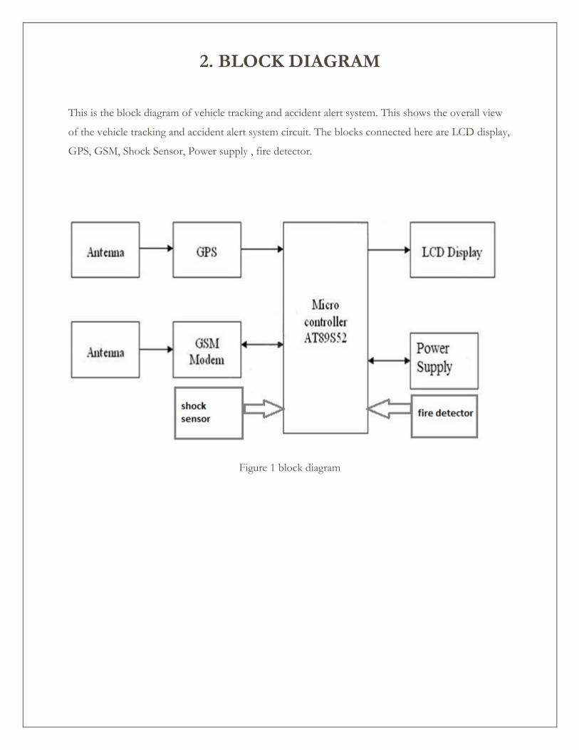
This is the block diagram of vehicle tracking and accident alert system. This shows the overall view
of the vehicle tracking and accident alert system circuit. The blocks connected here are LCD display,
GPS, GSM, Shock Sensor, Power supply , fire detector.
Figure 1 block diagram
2.1 Concept and Overview
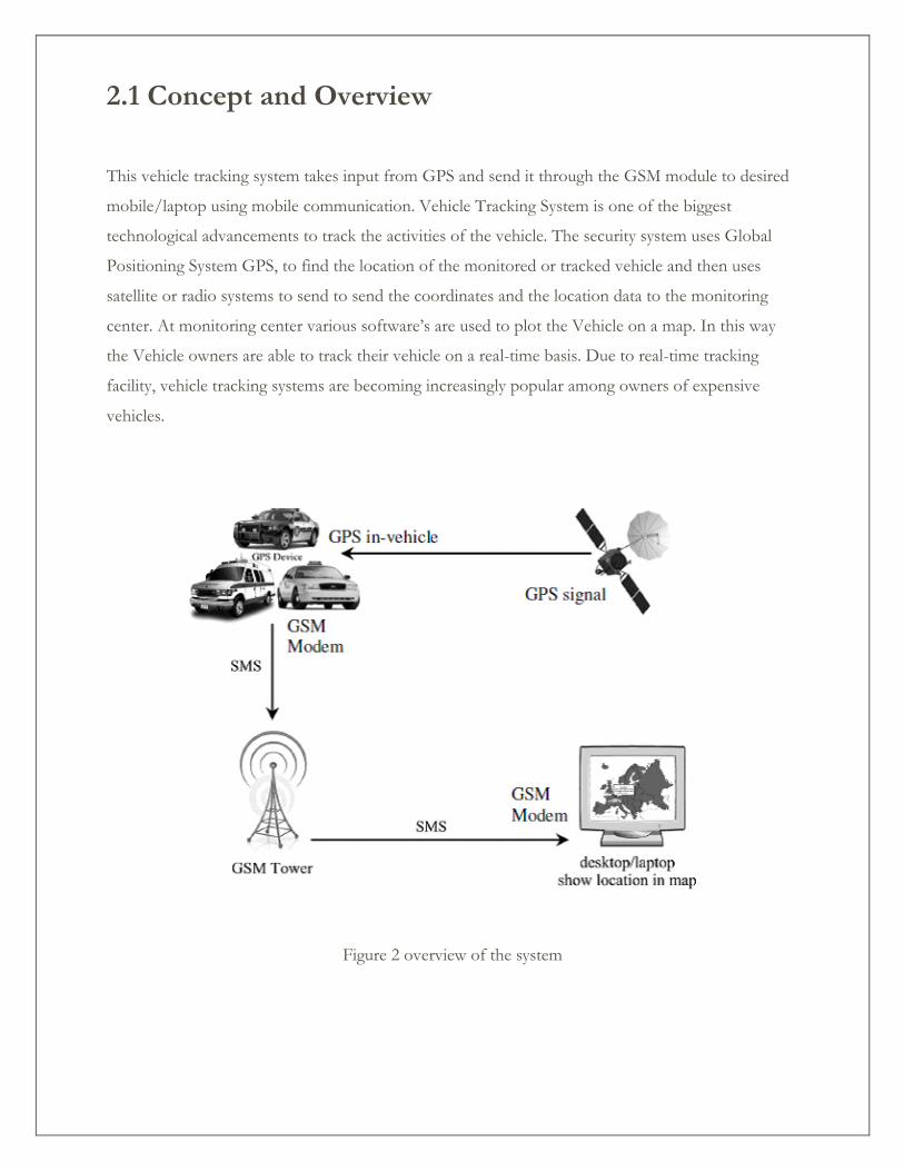
This vehicle tracking system takes input from GPS and send it through the GSM module to desired
mobile/laptop using mobile communication. Vehicle Tracking System is one of the biggest
technological advancements to track the activities of the vehicle. The security system uses Global
Positioning System GPS, to find the location of the monitored or tracked vehicle and then uses
satellite or radio systems to send to send the coordinates and the location data to the monitoring
center. At monitoring center various software’s are used to plot the Vehicle on a map. In this way
the Vehicle owners are able to track their vehicle on a real-time basis. Due to real-time tracking
facility, vehicle tracking systems are becoming increasingly popular among owners of expensive
vehicles.
Figure 2 overview of the system
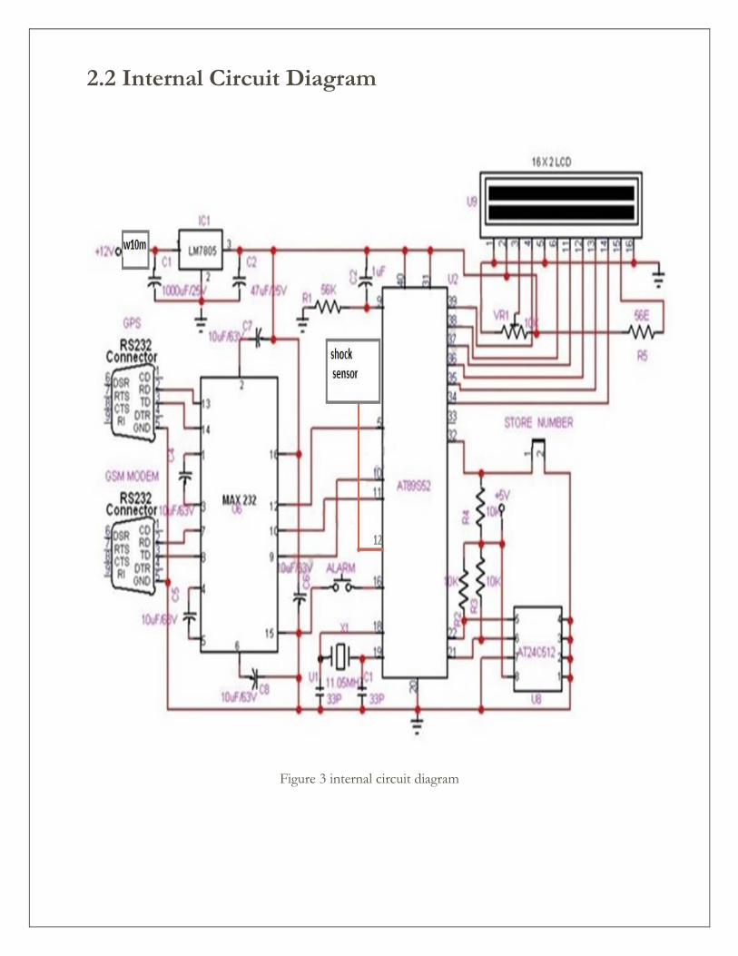
2.2 Internal Circuit Diagram
Figure 3 internal circuit diagram
3. HARDWARE
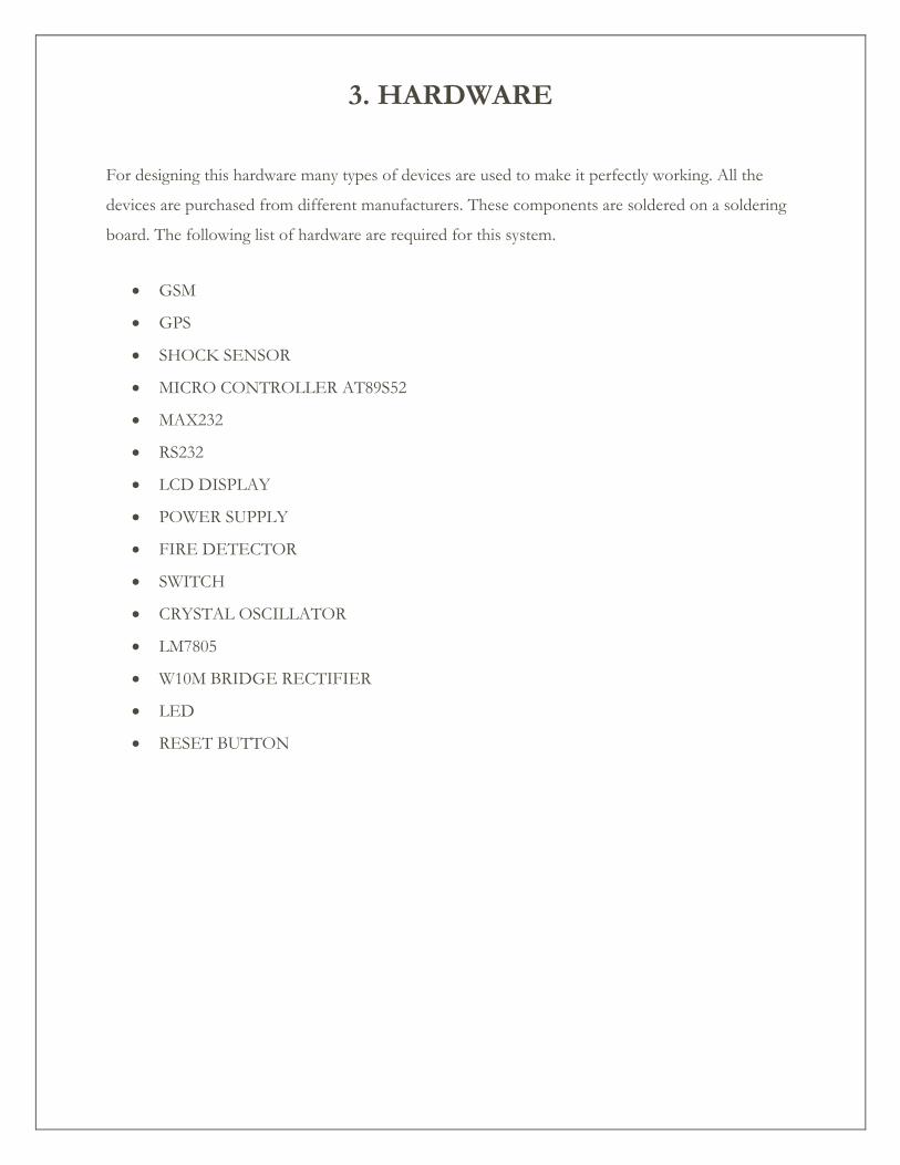
For designing this hardware many types of devices are used to make it perfectly working. All the
devices are purchased from different manufacturers. These components are soldered on a soldering
board. The following list of hardware are required for this system.
GSM
GPS
SHOCK SENSOR
MICRO CONTROLLER AT89S52
MAX232
RS232
LCD DISPLAY
POWER SUPPLY
FIRE DETECTOR
SWITCH
CRYSTAL OSCILLATOR
LM7805
W10M BRIDGE RECTIFIER
LED
RESET BUTTON
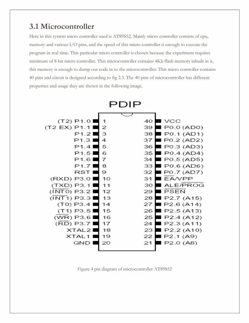
3.1 Microcontroller Here in this system micro controller used is AT89S52. Mainly micro controller consists of cpu,
memory and various I/O pins, and the speed of this micro controller is enough to execute the
program in real time. This particular micro controller is chosen because the experiment requires
minimum of 8-bit micro controller. This microcontroller contains 4Kb flash memory inbuilt in it,
this memory is enough to dump our code in to the microcontroller. This micro controller contains
40 pins and circuit is designed according to fig 2.3. The 40 pins of microcontroller has different
properties and usage they are shown in the following image.
Figure 4 pin diagram of microcontroller AT89S52
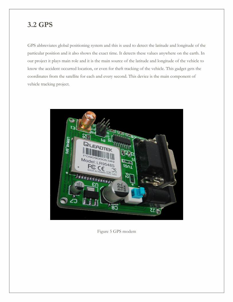
3.2 GPS
GPS abbreviates global positioning system and this is used to detect the latitude and longitude of the
particular position and it also shows the exact time. It detects these values anywhere on the earth. In
our project it plays main role and it is the main source of the latitude and longitude of the vehicle to
know the accident occurred location, or even for theft tracking of the vehicle. This gadget gets the
coordinates from the satellite for each and every second. This device is the main component of
vehicle tracking project.
Figure 5 GPS modem
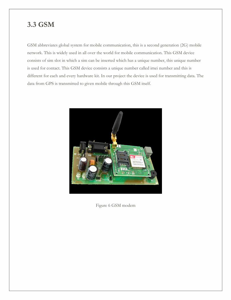
3.3 GSM
GSM abbreviates global system for mobile communication, this is a second generation (2G) mobile
network. This is widely used in all over the world for mobile communication. This GSM device
consists of sim slot in which a sim can be inserted which has a unique number, this unique number
is used for contact. This GSM device consists a unique number called imei number and this is
different for each and every hardware kit. In our project the device is used for transmitting data. The
data from GPS is transmitted to given mobile through this GSM itself.
Figure 6 GSM modem
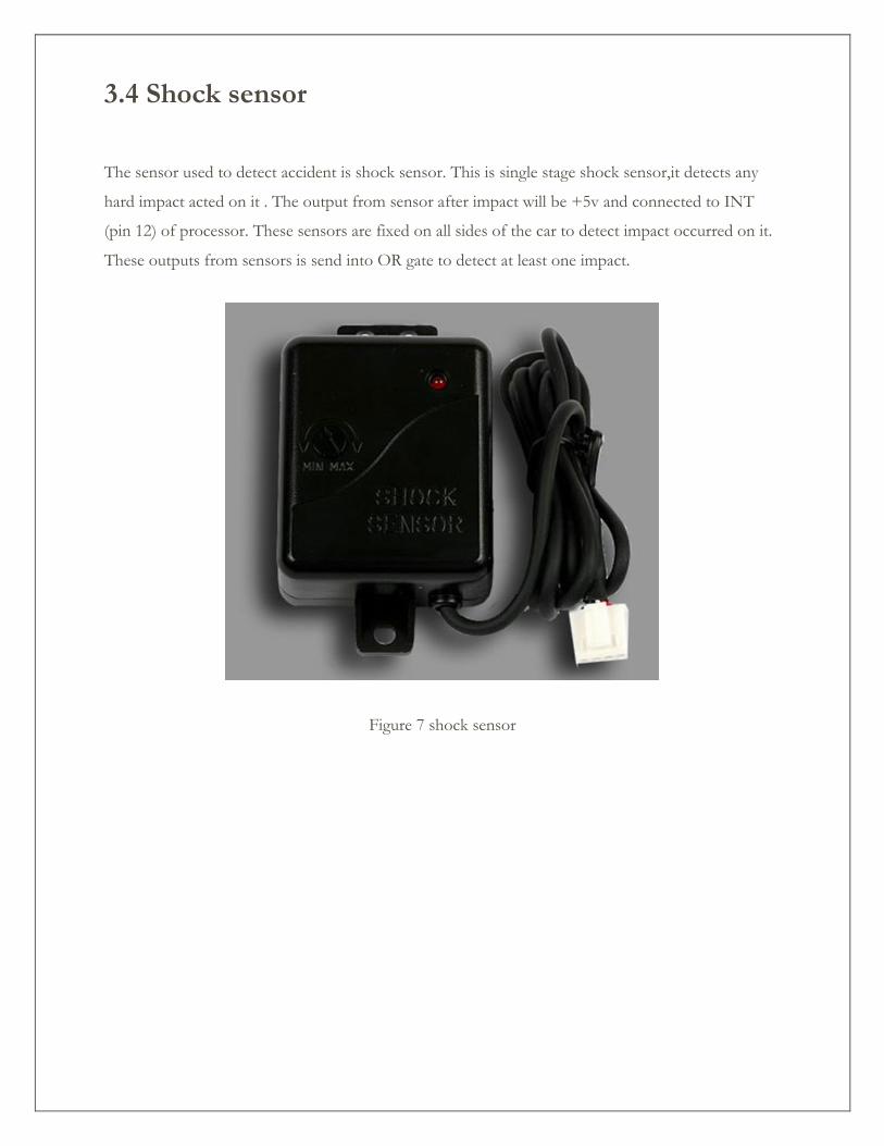
3.4 Shock sensor
The sensor used to detect accident is shock sensor. This is single stage shock sensor,it detects any
hard impact acted on it . The output from sensor after impact will be +5v and connected to INT
(pin 12) of processor. These sensors are fixed on all sides of the car to detect impact occurred on it.
These outputs from sensors is send into OR gate to detect at least one impact.
Figure 7 shock sensor
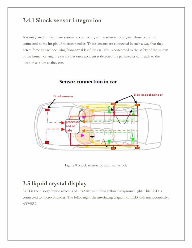
3.4.1 Shock sensor integration
It is integrated in the circuit system by connecting all the sensors to or gate whose output is
connected to the int pin of microcontroller. These sensors are connected in such a way that they
detect force impact occurring from any side of the car. This is concerned to the safety of the system
of the human driving the car so that once accident is detected the paramedics can reach to the
location as soon as they can.
Figure 8 Shock sensors position on vehicle
3.5 liquid crystal display LCD is the display device which is of 16x2 size and it has yellow background light. This LCD is
connected to microcontroller. The following is the interfacing diagram of LCD with microcontroller
AT89S52.
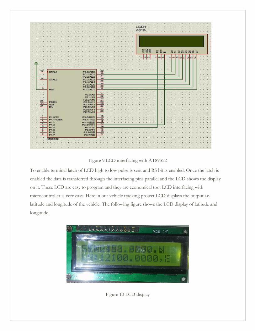
Figure 9 LCD interfacing with AT89S52
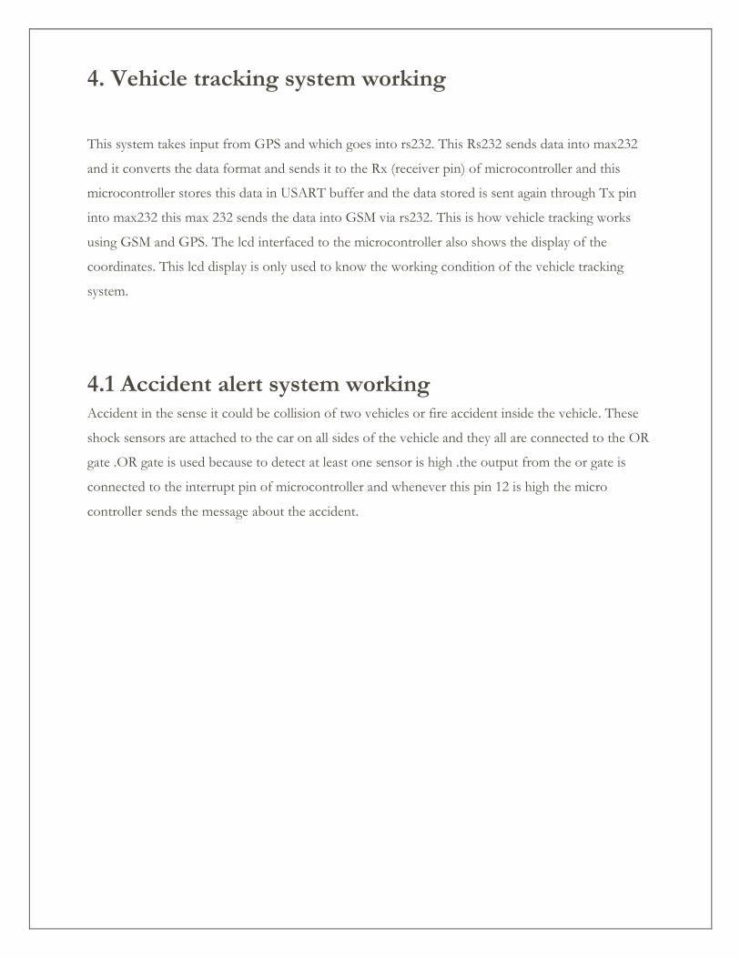
To enable terminal latch of LCD high to low pulse is sent and RS bit is enabled. Once the latch is
enabled the data is transferred through the interfacing pins parallel and the LCD shows the display
on it. These LCD are easy to program and they are economical too. LCD interfacing with
microcontroller is very easy. Here in our vehicle tracking project LCD displays the output i.e.
latitude and longitude of the vehicle. The following figure shows the LCD display of latitude and
longitude.
Figure 10 LCD display
4. Vehicle tracking system working
This system takes input from GPS and which goes into rs232. This Rs232 sends data into max232
and it converts the data format and sends it to the Rx (receiver pin) of microcontroller and this
microcontroller stores this data in USART buffer and the data stored is sent again through Tx pin
into max232 this max 232 sends the data into GSM via rs232. This is how vehicle tracking works
using GSM and GPS. The lcd interfaced to the microcontroller also shows the display of the
coordinates. This lcd display is only used to know the working condition of the vehicle tracking
system.
4.1 Accident alert system working Accident in the sense it could be collision of two vehicles or fire accident inside the vehicle. These
shock sensors are attached to the car on all sides of the vehicle and they all are connected to the OR
gate .OR gate is used because to detect at least one sensor is high .the output from the or gate is
connected to the interrupt pin of microcontroller and whenever this pin 12 is high the micro
controller sends the message about the accident.
5.Code written to the processor
#include<stdio.h>
#include<stdlib.h>
#define LCD_RS 3
#define LCD_RW 1
#define LCD_EN 2
/*----4x20 lcd display functions prototypes declarations--*/
void lcdinit(void);
void lcdcmd(char);
void lcddata(char);
void lcdstring(char*);
void lcdline1(void);
void lcdline2(void);
void lcdline3(void);
void lcdline4(void);
void clearscreen(void);
void gsmlink(void);
void sms_send(void);
void disp_gpsdata(void);
void gps_check(void);
/*----serial communication functions prototypes declarations---*/
void USART_Init(void);
void USART_Transmit(unsigned char data );
void usart_puts(char *ptr);
void delay(unsigned char del);
/*----globlal variables declarations----*/
int i,k=0;
char d[75],start=0,rmcok=0,disp;
char gpsdata,cnt;
/*.......main function..............*/
int main(void)
{
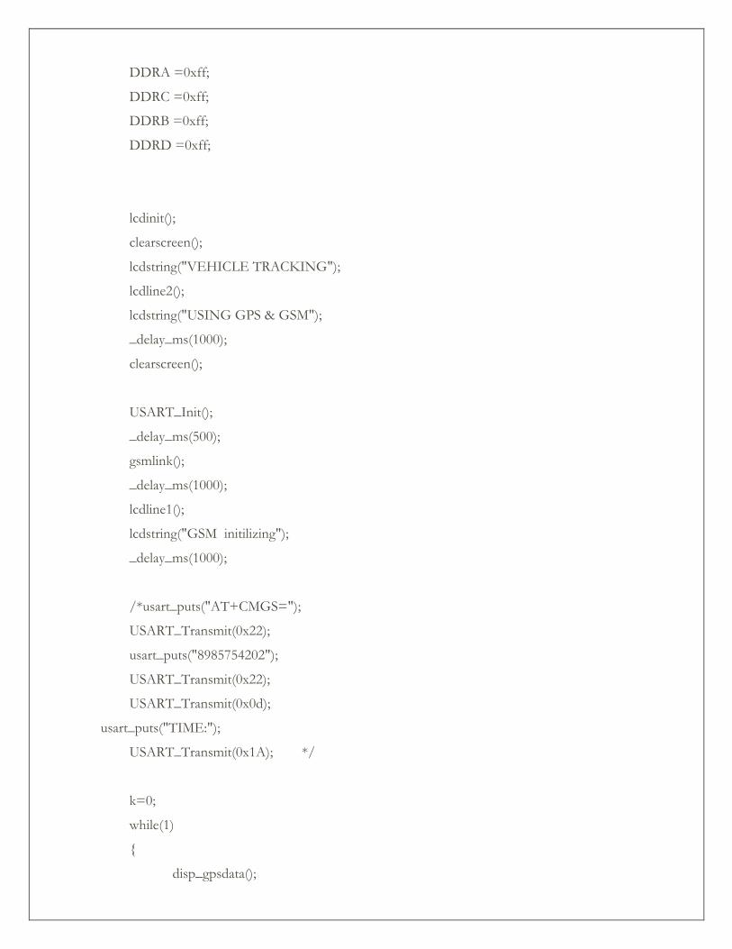
DDRA =0xff;
DDRC =0xff;
DDRB =0xff;
DDRD =0xff;
lcdinit();
clearscreen();
lcdstring("VEHICLE TRACKING");
lcdline2();
lcdstring("USING GPS & GSM");
_delay_ms(1000);
clearscreen();
USART_Init();
_delay_ms(500);
gsmlink();
_delay_ms(1000);
lcdline1();
lcdstring("GSM initilizing");
_delay_ms(1000);
/*usart_puts("AT+CMGS=");
USART_Transmit(0x22);
usart_puts("8985754202");
USART_Transmit(0x22);
USART_Transmit(0x0d);
usart_puts("TIME:");
USART_Transmit(0x1A); */
k=0;
while(1)
{
disp_gpsdata();
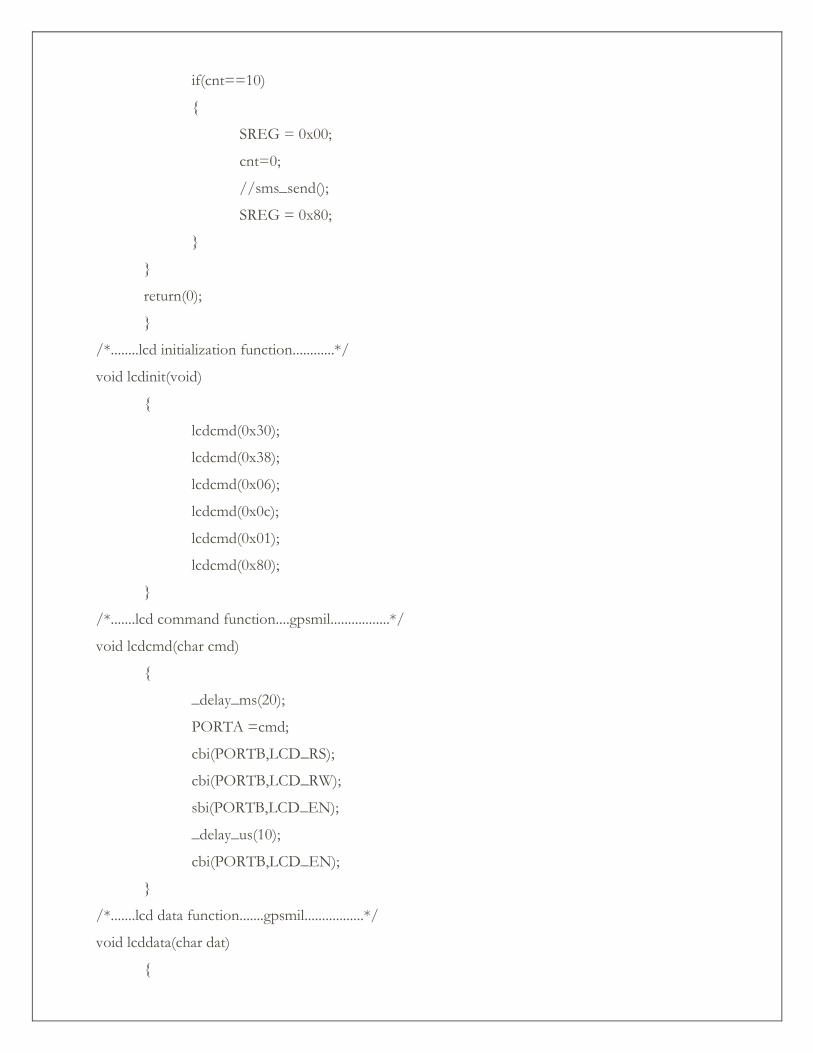
if(cnt==10)
{
SREG = 0x00;
cnt=0;
//sms_send();
SREG = 0x80;
}
}
return(0);
}
/*........lcd initialization function............*/
void lcdinit(void)
{
lcdcmd(0x30);
lcdcmd(0x38);
lcdcmd(0x06);
lcdcmd(0x0c);
lcdcmd(0x01);
lcdcmd(0x80);
}
/*.......lcd command function....gpsmil.................*/
void lcdcmd(char cmd)
{
_delay_ms(20);
PORTA =cmd;
cbi(PORTB,LCD_RS);
cbi(PORTB,LCD_RW);
sbi(PORTB,LCD_EN);
_delay_us(10);
cbi(PORTB,LCD_EN);
}
/*.......lcd data function.......gpsmil.................*/
void lcddata(char dat)
{
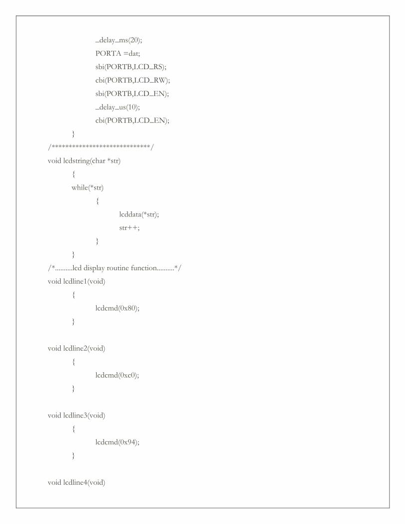
_delay_ms(20);
PORTA =dat;
sbi(PORTB,LCD_RS);
cbi(PORTB,LCD_RW);
sbi(PORTB,LCD_EN);
_delay_us(10);
cbi(PORTB,LCD_EN);
}
/*****************************/
void lcdstring(char *str)
{
while(*str)
{
lcddata(*str);
str++;
}
}
/*..........lcd display routine function..........*/
void lcdline1(void)
{
lcdcmd(0x80);
}
void lcdline2(void)
{
lcdcmd(0xc0);
}
void lcdline3(void)
{
lcdcmd(0x94);
}
void lcdline4(void)
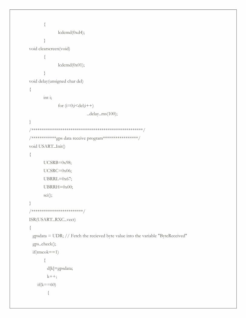
{
lcdcmd(0xd4);
}
void clearscreen(void)
{
lcdcmd(0x01);
}
void delay(unsigned char del)
{
int i;
for (i=0;i<del;i++)
_delay_ms(100);
}
/******************************************************/
/************gps data receive program*****************/
void USART_Init()
{
UCSRB=0x98;
UCSRC=0x06;
UBRRL=0x67;
UBRRH=0x00;
sei();
}
/*************************/
ISR(USART_RXC_vect)
{
gpsdata = UDR; // Fetch the recieved byte value into the variable "ByteReceived"
gps_check();
if(rmcok==1)
{
d[k]=gpsdata;
k++;
if(k==60)
{
rmcok=0;
disp=1;
}
}
}
void usart_ puts(char *ptr)
{
while(*ptr)
{
USART _Transmit(*ptr);
ptr++;
}
i=0;
}
/***************************/
void USART_Transmit( unsigned char data )
{
while ( !( UCSRA & (1<<UDRE)) );
UDR = data;
}
/******************************************************/
void disp_gpsdata(void)
{
_delay_ms(100);
clearscreen();
if(disp==1)
{
//cli();
disp=0;
SREG = 0x00;
_delay_ms(1000);
/* //lcdline1();
// lcdstring("TIME:"); //hrs
for(k=5;k<=6;k++)
{
//lcddata(d[k]);
}
//lcdstring(":");
for(k=7;k<=8;k++)
{
//lcddata(d[k]);
}
//lcdstring(":");
for(k=9;k<=10;k++)
{
//lcddata(d[k]);
}*/
lcdline1();
lcdstring("LON:");
for(k=17;k<=27;k++)
{
lcddata(d[k]);
}
lcdline2();
lcdstring("LAT:");
for(k=29;k<=40;k++)
{
lcddata(d[k]);
}
//lcdline4();
//lcdstring("DATE:");
for(k=50;k<=55;k++)
{
//lcddata(d[k]);
}
cnt++; //sei();
_delay_ms(1000);
k=0;
_delay_ms(1000);
_delay_ms(1000);
_delay_ms(1000);
sms_send();
SREG = 0x80;
}
}
/**********************************/
void gps_check(void)
{
if(gpsdata=='R')
{
d[k]=gpsdata;
k++;
}
if( (d[0]=='R')&( gpsdata=='M'))
{
d[k]=gpsdata;
k++;
}
if((d[0]=='R')&(d[1]=='M')& (gpsdata=='C'))
{
d[k]=gpsdata;
k++;
rmcok=1;
}
}
/****************linking GSM to AVr*****************************/
void gsmlink(void)
{
usart_puts("AT"); USART_Transmit(0x0D); _delay_ms(20);
clearscreen();lcdline1(); lcdstring("AT");
usart_puts("ATE0"); USART_Transmit(0x0D); _delay_ms(20);
clearscreen();lcdline1(); lcdstring("ATE0");
usart_puts("AT+CSMS=0"); USART_Transmit(0x0D); _delay_ms(20);
clearscreen();lcdline1(); lcdstring("AT+CSMS=0");
usart_puts("AT+IPR=9600"); USART_Transmit(0x0D); _delay_ms(20);
clearscreen();lcdline1(); lcdstring("AT+IPR=9600");
usart_puts("AT+CMGF=1"); USART_Transmit(0x0D); _delay_ms(20);
clearscreen();lcdline1(); lcdstring("AT+CMGF=1");
usart_puts("AT&W"); USART_Transmit(0x0D); _delay_ms(20);
clearscreen();lcdline1(); lcdstring("AT&W");
usart_puts("AT+CNMI=2,1,0,0,0"); USART_Transmit(0x0D); _delay_ms(20);
clearscreen();lcdline1(); lcdstring("AT+CNMI=2,1,0,0,0");
}
/*******************SIM DETAILS*******************************/
void sms_send(void)
{
i=0;
k=0;
usart_puts("AT+CMGS=");
USART_Transmit(0x22);
usart_puts("8985754202");
USART_Transmit(0x22);
USART_Transmit(0x0d);
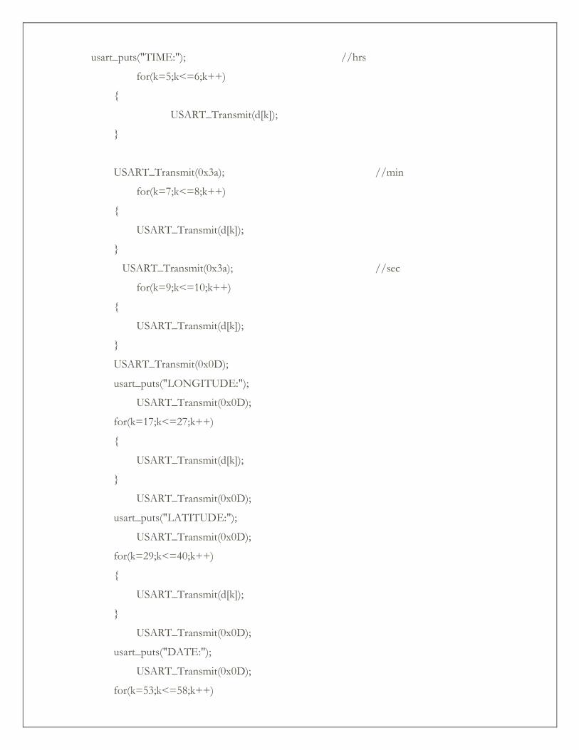
usart_puts("TIME:"); //hrs
for(k=5;k<=6;k++)
{
USART_Transmit(d[k]);
}
USART_Transmit(0x3a); //min
for(k=7;k<=8;k++)
{
USART_Transmit(d[k]);
}
USART_Transmit(0x3a); //sec
for(k=9;k<=10;k++)
{
USART_Transmit(d[k]);
}
USART_Transmit(0x0D);
usart_puts("LONGITUDE:");
USART_Transmit(0x0D);
for(k=17;k<=27;k++)
{
USART_Transmit(d[k]);
}
USART_Transmit(0x0D);
usart_puts("LATITUDE:");
USART_Transmit(0x0D);
for(k=29;k<=40;k++)
{
USART_Transmit(d[k]);
}
USART_Transmit(0x0D);
usart_puts("DATE:");
USART_Transmit(0x0D);
for(k=53;k<=58;k++)
{
USART_Transmit(d[k]);
}
USART_Transmit(0x1A);
clearscreen();
lcdstring(" MSG SENT");
k=0;
}
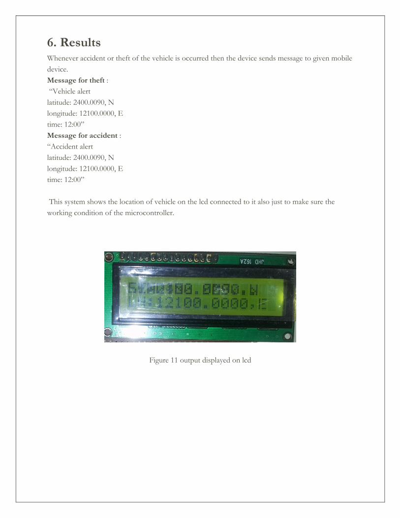
6. Results Whenever accident or theft of the vehicle is occurred then the device sends message to given mobile
device.
Message for theft :
“Vehicle alert
latitude: 2400.0090, N
longitude: 12100.0000, E
time: 12:00”
Message for accident :
“Accident alert
latitude: 2400.0090, N
longitude: 12100.0000, E
time: 12:00”
This system shows the location of vehicle on the lcd connected to it also just to make sure the
working condition of the microcontroller.
Figure 11 output displayed on lcd
7. Applications Commercial fleet operators are by far the largest users of vehicle tracking systems. These systems are
used for operational functions such as routing, security, dispatch and collecting on-board
information.
These are also used for fire detector in large vehicles like train, bus etc. because the vehicle like train
contains large number of people and the sending alert of fire accident can save many lives.
The applications for this project are in military, navigation, automobiles, aircrafts, fleet management,
remote monitoring, remote control, security systems, tele services, etc.
• Fleet monitoring
• Vehicle scheduling
• Route monitoring
• Driver monitoring
• Accident analysis
• Geo-fencing geo-coding
8. Conclusion Vehicle tracking system makes better fleet management and which in turn brings large profits. Better
scheduling or route planning can enable you handle larger jobs loads within a particular time.
Vehicle tracking both in case of personal as well as business purpose improves safety and security,
communication medium, performance monitoring and increases productivity. So in the coming year,
it is going to play a major role in our day-to-day living.
Main motto of the accident alert system project is to decrease the chances of losing life in such
accident which we can’t stop from occurring. Whenever accident is alerted the paramedics are
reached to the particular location to increase the chances of life. This device invention is much more
useful for the accidents occurred in deserted places and midnights. This vehicle tracking and
accident alert feature plays much more important role in day to day life in future.
9. Bibliography www.8051projects.com
www.wikipedia.org
www.atmel.com
www.tatateleservices.com
www.roseindia.net
[1] R.S GAONKAR Microprocessor architecture programming and
Application” WILEY EASTERN LTD, NEWDELHI
[2] KRISHNA KANT “Microprocessor and microcontroller” EASTERN
COMPANY EDITION NEW DELHI 2007
[3] DANIEL .W.LEWIS “Fundamental of embedded software “prentice
Hall of India, 2004
[4] WILLIAM STALLING “Wireless communication and
Networks”, 2nd edition, 2005 prentice hall of India