Embed Size (px)
Citation preview

Embedded Systems (CSCE 4114)
Vending Machine FSM
Zack Fravel
9/23/16
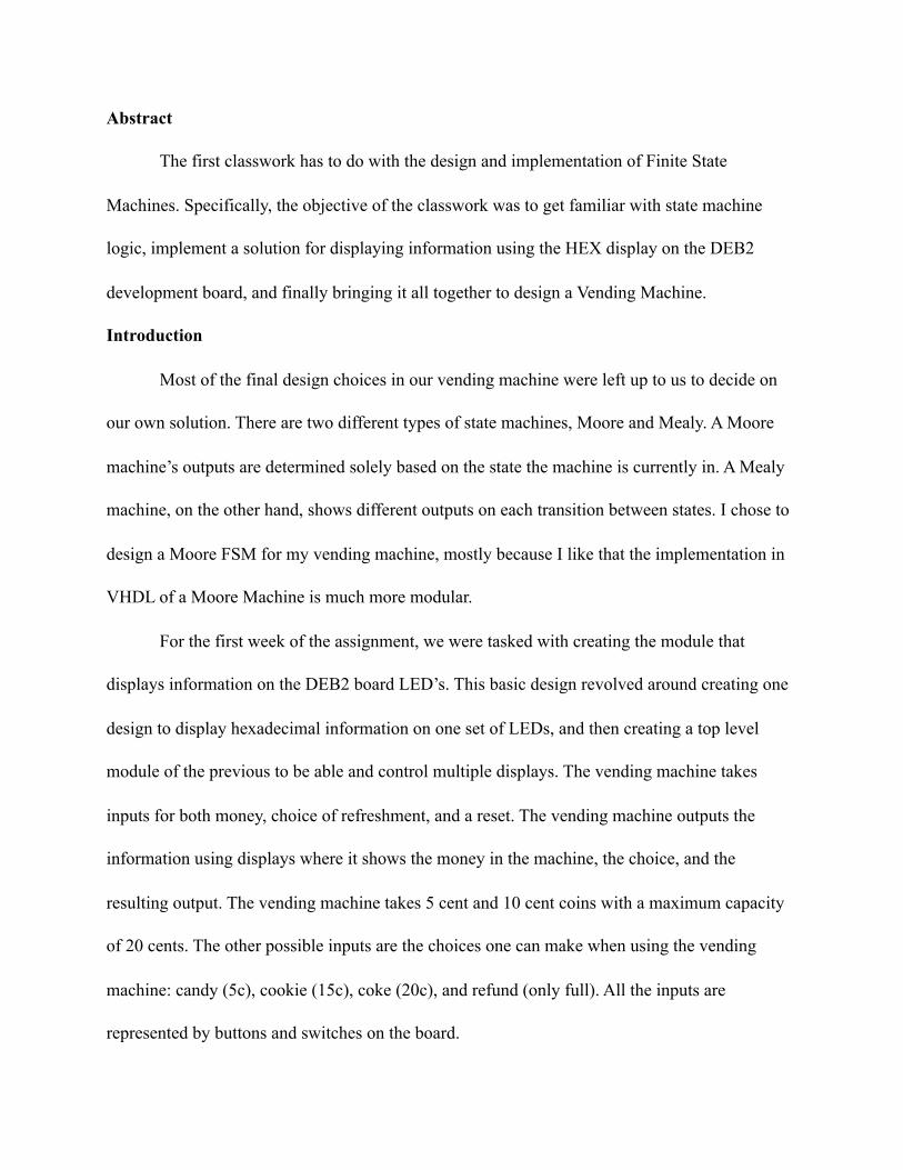
Abstract
The first classwork has to do with the design and implementation of Finite State
Machines. Specifically, the objective of the classwork was to get familiar with state machine
logic, implement a solution for displaying information using the HEX display on the DEB2
development board, and finally bringing it all together to design a Vending Machine.
Introduction
Most of the final design choices in our vending machine were left up to us to decide on
our own solution. There are two different types of state machines, Moore and Mealy. A Moore
machine’s outputs are determined solely based on the state the machine is currently in. A Mealy
machine, on the other hand, shows different outputs on each transition between states. I chose to
design a Moore FSM for my vending machine, mostly because I like that the implementation in
VHDL of a Moore Machine is much more modular.
For the first week of the assignment, we were tasked with creating the module that
displays information on the DEB2 board LED’s. This basic design revolved around creating one
design to display hexadecimal information on one set of LEDs, and then creating a top level
module of the previous to be able and control multiple displays. The vending machine takes
inputs for both money, choice of refreshment, and a reset. The vending machine outputs the
information using displays where it shows the money in the machine, the choice, and the
resulting output. The vending machine takes 5 cent and 10 cent coins with a maximum capacity
of 20 cents. The other possible inputs are the choices one can make when using the vending
machine: candy (5c), cookie (15c), coke (20c), and refund (only full). All the inputs are
represented by buttons and switches on the board.

Design and Implementation
In chronological order we designed an LED module, an array of LED’s, and an FSM to
control the state of the LEDs. All VHDL files are attached at the end of the report as screenshots
as well as the original .vhd files in the report package. The seven segment display is our first
order of business. Each SSD can be thought of a std_logic_vector of 7 bits. Each bit represents
one of the seven segments the display is able to light up. The LED’s on the board are designed so
that “0” actually represents the on-state and “1” for off. With that in mind, If we take a 4 bit input
we’re able to create a case statement and have a different configuration of LED’s for each case
on the 4 bit input. This is exactly what was accomplished, each input asserts its hexadecimal
representation of itself on the SSD output for all 16 combinations. The module that lets us
control four displays at once is a little more complex, its diagram is shown below.
Four Display Diagram
Figure 1
It can be seen from the diagram that the module continuously counts through the four different
inputs to the mux, which represent 4 different inputs to an SSD module, and sends them one at a

time to a single SSD module. This SSD module then sends its outputs to the output on the parent
four display module who’s outputs are continuously scrolling through each of the 4 SSD’s. This
is happening at a rate so fast however, it’s not noticeable to the human eye. In effect, this allows
us to control 4 SSD’s with only one module and one set of inputs.
Now that we have a way to display our vending machine information, we’re able to
design the FSM (Finite State Machine). To recap, out FSM takes in seven inputs (Reset, Nickel,
Dime, Candy, Cookie, Coke, and Refund) and sends out three outputs (Cash, Choice, and Result)
which is broken down into four SSD’s. I have decided with my state machine to have the Cash
be represented by the first two displays, the Choice the third, and the Result on the final display.
Candy costs 5 cents, Cookies 15 cents, Coke 20 cents, and the only refund the machine can do is
full, not partial. Below is a graphical representation of my FSM design for the vending machine;
wherever there is an X, that means there could be a number of possible configurations depending
on the inputs. Vending Machine Diagram
Figure 2

My state machine has nine total possible states, their names being fairly self descriptive. I have
one state dedicated to each different sum of cash that can be possibly dispensed into the machine
(20 cents maximum) as well as states for each output and of course an initial state. Below I have
also included the parent diagram for the whole vending machine system.
Vending Machine
Figure 3
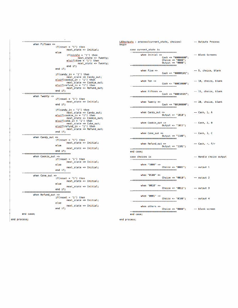
The implementation in VHDL of the FSM is fairly straight forward. I declare my inputs
and outputs exactly as they’re shown above where it says FSM. The inputs all being std_logic
and the outputs being std_logic_vector(7 downto 0) for cash and (3 downto) for the other two.
Choice is represented in hexadecimal as 1, 2, 3, 4 (Candy, Cookie, Coke, Refund) and the
outputs A, B, C, -blank- or d on the SSD. I declare a type STATE in my architecture to represent
all the possible states and create two signals, next_state and current_state to tell the tool which
state I’m in and where I’m going to be. Along with that, I also create a signal called choices,
which is a concatenation of all the possible choice inputs and is being fed directly to the output
process.

The logic of the state machine is broken up into three processes. First, I have my Current
State Transition, which is sensitive to the clock and reset. Within this first process is a simple if
else if statement that changes my current state signal to whatever the next state signal is, unless
Reset = ‘1,’ then current state is Initial. The second process, and by far the longest to write, is the
Next State Transition Process. This process is sensitive to all inputs and is responsible for
making sure the state machine correctly changes state based on a pattern of inputs. How this is
implemented in VHDL is a case statement that is accounting for each case of the signal
current_state and tells the circuit where to go based on the inputs in each case with if statements.
In every case, the first if statement is always if ( Reset = ‘1’ ) then next_state <= Initial. After
that, the nested if statement within the else tells the FSM which state to move to based on
whether a nickel or dime is inserted. Along with that, on each case where there is money in the
machine, the FSM also has to check whether or not any of the choice inputs are asserted, if so
then it should change to the appropriate output state given there’s an appropriate amount of cash
in the vending machine. Once all of those cases are accounted for, then I just had to make sure
that for the output states the next_state is always Initial so the vending machine can reset.
The final process is much shorter than the second and is responsible for setting the output
of the FSM correctly based on the current state. The output process also has a choice case
statement so the vending machine displays user inputs to the LED’s, regardless if the transaction
is legal or not. If the transaction is allowed, the output will show but it won’t if theres not enough
cash. The current state case statement just assigns the outputs respectively to each case as
described on the previous page. All three of these processes run concurrently and the resulting
logic is the behavior we were striving for.

Results
Once I had my design compiled and was confident it would perform the way it was
specified, I designed a testbench to simulate the design. My testbench runs through five different
scenarios to show that all of the functionality performs as advertised. I initialize a 20 ns clock
cycle and instantiate my FSM module into the testbench with corresponding inputs/outputs.
Below is the first half of the simulation.
Simulation (pt. 1)
Figure 4
The first 100 ns of the simulation runs through one of the simplest cases, requesting a candy and
inserting a nickel, which correctly outputs “A” to the Result display. During the duration the

candy is being requested, “1” is being displayed on the Choice display. It can also be seen that
the Cash is correctly shown as well on the first two displays. The second test states with a dime
being inserted and the FSM correspondingly changes states. Then, the user requests a coke and
inserts two nickels. Only after the FSM makes the two necessary transitions to Twenty is it able
to make the transition to Coke_out and output “C” on the display. In my test bench I had to split
up each “coin insertion” by about 20 nanoseconds to account for the delay in the state transition.
The second half of the simulation shows some more uncommon cases and how the
vending machine will handle it properly.
Simulation (pt. 2)
Figure 5
The third test is a test of the Reset functionality, mostly. I created a case where the user inputs
two nickels and requests a Coke, but before inserting 20 cents I reset the machine. This shows
both that the reset works and the output logic works as well. The fourth test shows a case where

the user requests a cookie and inserts more than the appropriate amount of Cash, but still
receives the appropriate output, “B.” Finally, the fifth test shows the refund function working
properly and displaying “D” after the user inputs 15 cents. The FSM then resets and the
simulation is complete. When implemented on the board, each of the coins are mapped to two of
the push buttons and the choices and reset are represented by switches.
In conclusion, a previously designed SSD module and designing a Moore FSM using
three distinct processes, I was able to successfully design and implement a vending machine as
specified by the classwork assignment.