Embed Size (px)
Citation preview

Ver.1.3

Introduction
This service manual describes the steps to maintain the Baroness Greens Mower LM18G, LM56G and
LM66T as well as the resources for diagnosing malfunctions and other issues.
The content is organized by categories of representative maintenance methods.
Please refer to the appropriate chapter to address your mower’s particular condition.
Please note that there are no steps described in this manual for disassembling and maintaining engine and
other parts that are specifically to be repaired by the manufacturer.
Please contact the dealer where you purchased the product or Kyoeisha USA for a repair request.
Kyoeisha USA, Inc.
Notes
The specifications described in this manual are current as of December 2009.
There may be some changes made to the content of this manual for improvement at any time
without notice. When replacing parts, please always use genuine parts or those specified by Kyoeisha USA.
Kyoeisha USA will not be responsible for the malfunction caused by the use of parts other than
genuine parts.

Specifications ......................................................................................................... 1
Part Names ........................................................................................................... 1
Maintenance Schedule ............................................................................................ 2
Locations for Greasing ............................................................................................. 2
How to Handle a Product Malfunction ......................................................................... 3
Required Tools ....................................................................................................... 6
Note for Inspection .................................................................................................. 6
[1] Replacing reel cutter and bedknife .......................................................................... 7
[2] How to replace the oil seal and tapered roller bearing .............................................. 13
[3] How to replace the bedknife ................................................................................ 17
[4] Installing of the reel cover .................................................................................. 22
[5] Overhaul of the inside of the gear case (left) ........................................................... 23
[6] Overhaul of the inside of the gear case (right) ......................................................... 25
[7] Removing/installing the drum assembly ................................................................ 26
[8] Disassembling/assembling the drum ..................................................................... 28
[9] Removing/installing/disassembling/assembling the transmission shaft ......................... 30
[10] Disassembling/assembling/adjusting the engine clutch area .................................... 34
[11] Disassembling/assembling/adjusting the brake ...................................................... 37
[12] Disassembling/assembling the front roller (with a groomer) ...................................... 39
[13] Disassembling/assembling the front roller (without a groomer) .................................. 44
[14] Disassembling/assembling/adjusting the front groomer ........................................... 45
[15] Setting of dethatching blades ............................................................................ 47
[16] Adjusting the front groomer ............................................................................... 48
[17] Disassembling/assembling the IGCA roller ........................................................... 49
[18] Adjusting the arm stopper ................................................................................. 54
[19] Reference ..................................................................................................... 55
Table of Contents

1 1
Specifications
Part Names
Head light switch
Throttle leverHandle
Engine clutch cover
Blade reel
Engine switch
Engine switch cordBrake lever
Drum wheel
Wheel shaft
Traveling wheel
Grass catcher
Front rollerFront groome
Safety lock lever
Main clutch lever
Head lampEngine
LM56GLM18GModel LM66T
Length (with grass catcher) 54.5 in. (138.5cm) 55.3 in. (140.5cm)
33.1 in. (84.2cm) 37 in. (94.2cm) 40 in. (103cm)Width (without travelling wheels)
45.2in. (114.7 cm)
no groomer
fully optioned
202 lbs. (91.5kg)211 lbs. (95.7kg) 214 lbs. (97kg)
236 lbs. (107kg)218 lbs. (99kg) 223 lbs. (101kg)
22 in. (55.6cm)18 in. (45.6cm) 26 in. (64.6cm)Mowing width
Reel diameter
Speed (km/h)
5.04 in. (ø 12.8cm)
Number of reel blades
Cutting height (min.~ max.)
0.08 in.~1.14 in. (2.0mm~28.5mm)
Mowingweight
Mowingsection
* When equipped with 1.5 mm bedknife.
9(option), 1111 7, 9, or 11
Eff cutting height(min. ~ max.)
*0.10 in.~1.06 in. (2.5mm~27mm)*0.10 in.~0.35 in.(2.5mm~9mm)
4.8 km/h (3 mph) @3,000 rpm
Engine Honda GX120U1 2.6 kw (3.5 hp) / 3,600 rpm
Height (handle)
LM56GLM18GModel LM66T
Front groomer
Dethatching Reel
Rotary Brush
Working width
Number of Blades
Working width
Number of Blades
Working width
Turning Diameter
16.4 in. (41.8cm)
64
16.2 in. (41.1cm)
32
15.3 in. (38.9cm)
2.4in. (6cm)
20 in. (51cm)
78
20 in. (51cm)
39
19.3 in. (49cm)
2.4in. (6cm)
23.6 in. (60cm)
92
23.6 in. (60cm)
46
22.4 in. (57cm)
2.4in. (6cm)

22 3
Locations for Greasing
Maintenance Schedule
Before use Every 8hr
Only after the initial operation
Every 10hr Every 50hrE
ngin
eM
ain
unit
Every 10hrLeft frame intermediate shaft (for Reel)Right & left frame intermediate shaft (for Drum)Differential gear partsVertical gear case intermediate shaft
Every 50hrLeft gear coverReel bearingFront rollerVertical gear case
Drum housing
Periodically fill up respective grease nipples.Exercise special care when greasing the sections where needle bearings are used.(Intermediate shaft of the right and left gears and the intermediate shaft of the groomer)Periodically fill up the grease nipples with approx. 1 g of grease (EXCELITE EP No.2) (one or two times with a compact manual grease pump).
Right-side main unit Left-side main unit
Every 10hr
Every 50hr
MaintenanceCleaning of each part/inspection of tighteningInspection and addition of fuelInspection and cleaning of air cleanerInspection and addition of engine oilEngine oil change [SAE30/0.6dm3 (0.6L)]
Inspection and cleaning of recoil starter dust proofing netCleaning of each part/inspection of tighteningInspection and adjustment of blade engagementInspection and adjustment of mowing heightGreasing and oilingRemoval of mown grass and dust

22 3
How to Handle a Product Malfunction
Is the mowing height on both sides adjusted to be the same?
Adjust the mowing height.
Is the bedknife cracked?
Replace the bedknife.
Does the front roller rattle up and down?
Replace the bearing on the front roller. Replace the front roller shaft.
Does the drum rattle up and down?
YES
Replace the bearing on the drum. Replace the drum shaft. Replace the bearing on the drum shaft.
Is the condition of the green spongy?
Replace the front roller with the straight roller.Select Low Clip.Use Groomer in Forward rotation.
Are the greens severely undulating?
If the groomer is attached, remove it. Replacethe roller bracket with the L-shaped roller bracket and bring the front roller closer to the reel.
Are the greens sloped?
Are the left frame and right frame possibly twisted?
Contact your dealership.
YES
YES
YES
YES
YES
YES
YES
NO
NO
Restore the bedknife to its normal conditionby lapping, grinding, or replacing it.
Does the reel cutter move sideways?
Is the spring pressure of the adjusting nut too light?
Is the sliding of the cam bush and frame extremely unsmooth?
Adjust the compression length of the spring (1-8) to 50mm.
Lightly engage the blades.Adjust light contact to reel and Bedknife.
NO
NO
NO
NO
Make sure the bearing on the reel cutter is properly tightened.(Refer to Section "6-5 Installation of the reel cutter" in the Owner's Manual.)
YES
NO
Has the bearing (1-36) cone been installed correctly?
Hammer in the cone again. Replace the reel bearing.
YES
NO
Do the cam bush and cutter pin (1-20) rattle a lot?
Replace the cam bush Replace the cutter pin.
YES
NO
Is the reel bearing not working correctly?
YES
Do the cam bush (1-22) and frame rattle together?
Replace the cam bush. Replace the frame.
When replacing the frames, make sure to reassemble the left and right frames parallel to the drum.
YES
NO
NO
NO
YES
YES
YES
NO
Clean and apply grease to the sliding sections to make the sliding smoother, and then reassemble.
Even though the blades are lightly engaged,streaks still appear.
[IMPORTANT]
[IMPORTANT]
Replace the reel bearing.(Replace it once a year.)
Apply enough grease to the reel bearing before installing it.
Replacing the oil seal at the same time is recommended.
NO
Change the mowing direction.
Has the bedknife become curvy?

44 5
YES
NO
NO
Are genuine parts used for the blades?
Replace the blades with genuine parts.
Does the Bedknife & Reel have too much contact?
Is the blade surface of the bedknife too rough?
Have you recently appliedtopdressing sand to the greens?
Engage the blades lightly.
Is the grain size of lapping powder #200 - #400?
Work sand into the greens.
Use the lapping powder of #200 - #400 grain size.
Adjust the compression length of the spring (1-8) to 50mm.
Is the sliding of the cam bush (1-22) and frame extremely unsmooth?
YES
Hammer in the cone again. Replace the reel bearing.
Replace the frame.
Cylindrically grind the reel. Replace the reel cutter.
Do the cam bush and cutter pin (1-20) rattle substantially?
Replace the cam bush. Replace the cutter pin.
YES
NO
Is the reel bearing not working correctly?
Replace the reel bearing.(Replace it once a year)
YES
Do the cam bush (1-22) and frame rattle together?
Replace the cam bush. Replace the frame.
YES
NO
Is the spring pressure of the adjusting lever too light? Clean and apply grease to the sliding
sections to make the sliding smoother, and then reassemble.
YES
YES
YES
When replacing the frames, make sure to reassemble the left and right frames parallel to the drum.
Apply enough grease to the reel bearing before installing it. Replacing the oil seal at the same time is recommended.
NO
Is the volume of sand to right?
Is the groomer used?
YES
Is the reel cutter not working consistent contact across the whole surface of the bedknife?
YES
YES
YES
NO
NO
The blades have been adjusted to be lightly engaged but now they are not cutting well.
Stop using the groomer. Raise the groomer's height.
Has the bearing (1-36) cone been installed correctly?
YES
YES
YES
YES
Is the frame warped around where the reel bearing is installed?
Does the reel cutter shaft shake, or is it bent?
Let the topdressing sand settle down (by working it into the greens, and water before mowing).
YES
NO
YES
NO
NO
[IMPORTANT]
[IMPORTANT]

44 5
Is the roller bracket secured?
Is the mower adjusted to the correct mowing height?
Adjust the mowing height.
Does the front roller rattle up and down?
Replace the bearing on the front roller. Replace the front roller shaft.
Tighten and secure the bracket. Replace the locking screw.
Does the drum rattle up and down?
YES
Replace the bearing on the drum. Replace the drum shaft.Replace the bearing on the drum shaft.
Is cut grass frequently discarded?
The front roller could sink down due to the weight of the cut grass trapped inside the grass catcher.Replace the front roller with the straight roller.
Are the bedknife and mowing height adjusted appropriately? (Refer to Section "5-13 Setting the mowing height gauge and blade thickness" in the Owner's Manual.)
Change the mowing height. Replace the bedknife.
Are the greens sloped?
Change the mowing direction.
YES
YES
YES
YES
YES
YES
NO
NO
NO
NO
NO
NO
NO
Is the condition of the greens spongy?
Raise height of out.Engage groomers, and run for one week.Top dress the green after one week and return to previous height of cut.
YES
NO
The greens' surface has been mowed smoothly.
Consider rolling the putting surface.
YES
Are the greens severely undulating?
Raise the mowing height.If the groomer is attached, remove it. Replace the roller bracket with the L-shaped roller bracket and bring the front roller closer to the reel.
YES
NO

66 7
Required Tools
*Tool sizes are indicated in mm.
Notes for Inspection
Always refer to this service manual as well as the owner’s manual when inspecting the mower.
During the inspection and operation of the mower, always wear gloves. “Left” and “right” directions in this manual are based on the viewpoint of the operator holding
the handle of the mower and facing the mowing direction.
When inspecting and repairing the mower, place it on a level surface and make sure all the
parts are in OFF position.
The build-up of cut grass and other debris at the intakes for engine cooling air and air cleaner,
or the muffler and exhaust pipe could lead to engine malfunction and overheating which could
cause a fire. When you see this build-up, stop the operation immediately. After the heated area
cools down enough, remove the build-up.
Do not touch the muffler and engine either during or right after operation as those areas can
be dangerously hot. This could cause burns.
Always keep clean the safety symbols and instructions attached to the mower. If they are lost
or damaged, replace them immediately with new ones.
Do not alter the machine. When replacing parts and grease, use those specified by Kyoeisha
USA.
The operation of a machine that has been altered or installed with parts other than those
specified by Kyoeisha USA could lead to mechanical damage or accident.
CAUTION
WARNING
Screw wrench 7 10 13 17 19 22 x 1 24 x 2
Allen key wrench 2 5 6
Longnose pliers
Pin remover 4
Stop ring pliers For opening & closing
Screwdriver Flathead x 2
Slide gauge
Clearance gauge (thickness gauge) 0.5 x 2 (included tool)
Hammer Metal, wooden, plastic
Other Magic marker, mowing height gauge, waste cloth, round bar Tool to hammer bearings Support to prevent engine oil from spilling when the engine tilts

66 7
Change lever
Travel ONDrum operationReel cutter stop
Travel ONDrum stop
Drum Operation
Reel cutter stop
Reel Cutter operationReel ON
* Please always wear gloves during this replacement as
it could be dangerous.
1) Set up the stand first, and then remove the traveling
wheels on both sides.
2) Place the mower on a stable workbench and lower the
handle.
3) Always set the change lever located at the top of the
left frame to the “Travel ON” position in order to keep
the mower from moving.
4) Engage parking brake.
5) If the engine is tilted, engine oil may spill out.
* Please keep the cylinder head’s vertical line slightly
above the line horizontal to the ground.
[1] Replacing reel cutter and bedknife
Traveling wheel
Stand
Handle
Lower
Cylinder head
Vertical line
Line horizontal to the ground

88 9
Groomer Ass'y
Tall nut
Square-rootbolt
Right caselocking bolt
Tall nut
Groomer Ass'y
Lower
Pull out to the right
Square-root bolt
Clutch cover
Bolt
6) Open the clutch cover [5-1,2,50].
7) Remove the bolts [1-25] on both sides that are holding
the reel cover.
Models equipped with a groomer
8) Unscrew the tall nuts [8-58] on both sides and the right
case locking bolt [8-60], and then remove the groomer
Ass’y.
* Lower the entire groomer Ass’y, and then pull it out to
the right after the groomer’s blade comes out of the
groove on the front roller.
Models not equipped with a groomer
Remove the front roller.
(Please refer to #1 - #4 of Section 12 on page 39, and
#2 of Section 13 on page 44.)
Cover
88 9
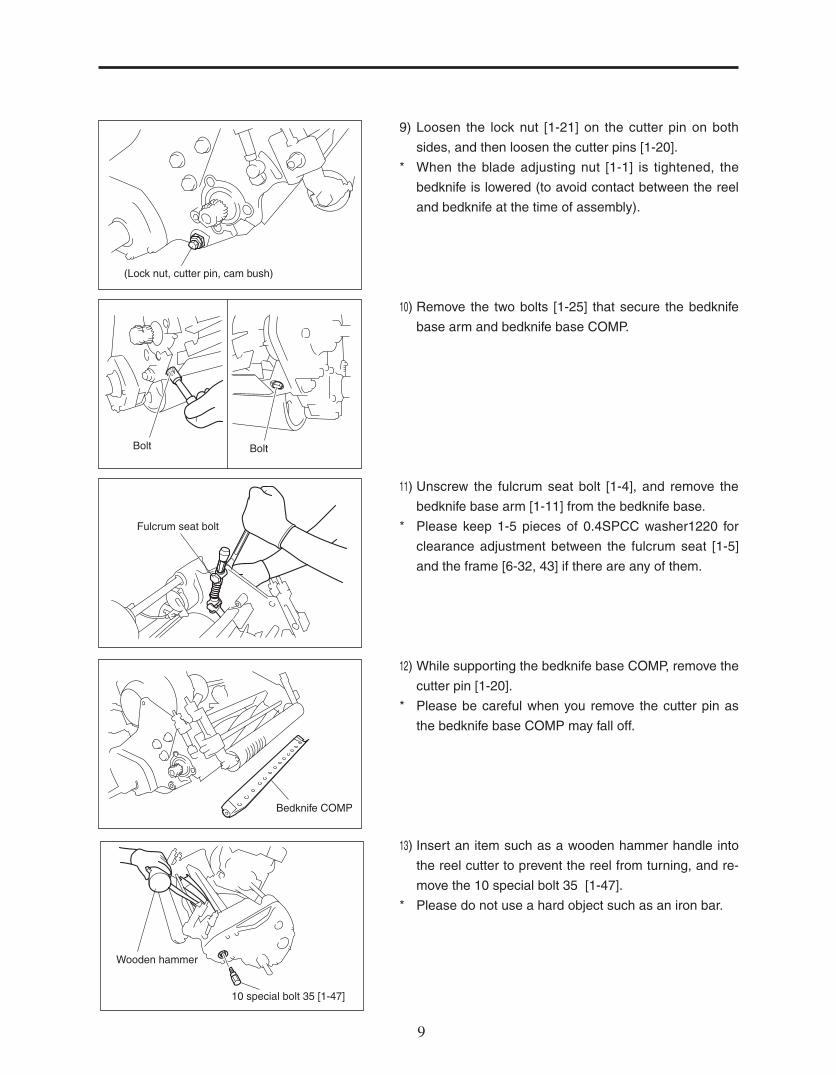
9) Loosen the lock nut [1-21] on the cutter pin on both
sides, and then loosen the cutter pins [1-20].
* When the blade adjusting nut [1-1] is tightened, the
bedknife is lowered (to avoid contact between the reel
and bedknife at the time of assembly).
10) Remove the two bolts [1-25] that secure the bedknife
base arm and bedknife base COMP.
11) Unscrew the fulcrum seat bolt [1-4], and remove the
bedknife base arm [1-11] from the bedknife base.
* Please keep 1-5 pieces of 0.4SPCC washer1220 for
clearance adjustment between the fulcrum seat [1-5]
and the frame [6-32, 43] if there are any of them.
12) While supporting the bedknife base COMP, remove the
cutter pin [1-20].
* Please be careful when you remove the cutter pin as
the bedknife base COMP may fall off.
13) Insert an item such as a wooden hammer handle into
the reel cutter to prevent the reel from turning, and re-
move the 10 special bolt 35 [1-47].
* Please do not use a hard object such as an iron bar.
(Lock nut, cutter pin, cam bush)
BoltBolt
Fulcrum seat bolt
Bedknife COMP
Wooden hammer
10 special bolt 35 [1-47]

1010 11
14) Remove the 6 bolt 10 , 6 S Washer , Clutch retainer
spring [6-56], and remove the H/L change lever [6-91]
from left side cover.
15) Loosen the hexagon socket head bolt on the wheel
driving fitting, amd then remove the fitting. Remove the
key [4-11] from the drum shaft.
16) Unscrew the six bolts [6-2], six bolts [6-30], one bolt [6-
94], and then detach the left cover [6-89].
* Do not force open the cover using an object such as a screw-
driver as it will scratch the adjoining surfaces.
If the cover doesn’t come off easily, remove it by tap-
ping those six locations (indicated by the arrows in the
left illustration) lightly with a wooden hammer.
17) Remove the washer [6-52,53], 36-tooth reel gear and
36-tooth / 45-tooth reel gear [6-54], 33-tooth reel gear
and 42-tooth reel gear [1-46].
18) Remove the reel gear securing nut [8-45] from the right
frame, then the 20-tooth reel gear [8-46], and then the
spring [1-35].
* The nut is left-hand threaded.
The 20-tooth reel gear has a specific orientation.
(Please confirm the orientation beforehand by referring
to [6-5] on page 14 of the owner’s manual.)
6 bolt 10
Clutch retainerspring
H/L change lever
6SWasher
Reel gearsecuring nut
20-tooth reel gear
Spring
Wheel driving fitting
8 Hexagon socket head bolt 25
Left cover
Bolt [6-2]Bolt [6-30]
Bolt [6-94]
washer [6-52]
washer[6-53]
36-tooth reel gear and 45-tooth reel gear
33-tooth reel gear and42-tooth reel gear
1010 11
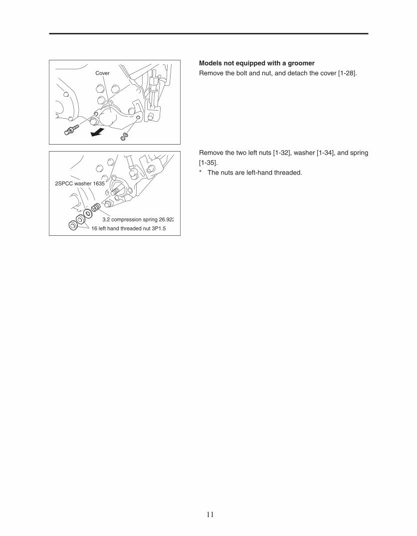
16 left hand threaded nut 3P1.5
3.2 compression spring 26.922
2SPCC washer 1635
Cover
Models not equipped with a groomer
Remove the bolt and nut, and detach the cover [1-28].
Remove the two left nuts [1-32], washer [1-34], and spring
[1-35].
* The nuts are left-hand threaded.
1212 13
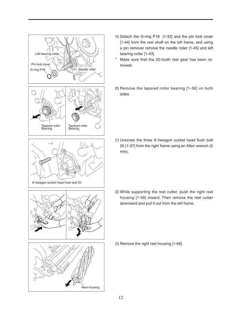
19) Detach the O-ring P18 [1-33] and the pin lock cover
[1-44] from the reel shaft on the left frame, and using
a pin remover remove the needle roller [1-45] and left
bearing collar [1-43].
* Make sure that the 20-tooth reel gear has been re-
moved.
20) Remove the tapered roller bearing [1-36] on both
sides.
21) Unscrew the three 8 hexagon socket head flush bolt
20 [1-37] from the right frame using an Allen wrench (5
mm).
22) While supporting the reel cutter, push the right reel
housing [1-58] inward. Then remove the reel cutter
downward and pull it out from the left frame.
23) Remove the right reel housing [1-58].
Pin lock cover
O-ring P18
Left bearing collar
Needle roller
Tapered rollerBearing
Tapered rollerBearing
8 hexagon socket head flush bolt 20
Reel housing

1212 13
1) Using a flathead screwdriver, remove the oil seal [1-38].
* Be careful not to scratch the frame.
2) Remove the bearing core[1-36] by hammering a flat-
head screwdriver equally around the bearing.
(Pay attention to the direction of hammering.)
* Since the outer bearing is not pressed fit, you can re-
move it smoothly by keeping it parallel to the housing
as you pull it out.
3) First, secure the right reel housing [1-58] with a vice,
and then remove the oil seal [1-38] using a flathead
screwdriver.
* Be careful not to scratch the right reel housing.
4) Remove the bearing core [1-36] by hammering a flat-
head screwdriver into it.
* Since the outer bearing is not pressed fit, you can re-
move it smoothly by keeping it parallel to the housing
as you pull it out.
5) Prepare the oil seal and tapered roller bearing. Make
sure that you always replace with a new part.
When replacing the tapered roller bearing [1-36], both
the core and bearing must be replaced as a set.
Grease the oil seal [1-38] and tapered roller bearing
[1-36]. (Rub enough grease on the tapered roller bear-
ing so that the grease may come out from the other
side. Apply enough grease on the lip surface of the oil
seal.)
[2] How to replace the oil seal and tapered roller bearing
Oil seal
Tapered roller bearing
Oil seal
Tapered roller bearing
Tapered rollerbearing
Oil seal

1414 15
6) Hammer the oil seal [1-38] into the housing.
* The oil seal needs to be hammered deep inside while
paying attention to the direction of the housing and oil
seal.
7) Hammer the tapered bearing core [1-36] into the hous-
ing [1-58].
* Please make sure that the direction of the bearing is
parallel to the housing.
8) Hammer the oil seal [1-38] from the inside.
9) Hammer the tapered bearing core [1-36] from the out-
side.
* Please make sure that the outer bearing is going in
parallel to the housing.
10) Install the housing on the reel cutter [1-39,40,41,42,63,71]
while paying attention to the direction of the housing.
* Be careful not to damage the oil seal.
Oil seal
Housing
Tapered roller bearing
Tapered roller bearing
Oil seal
Oil seal
Tapered roller bearing
Oil seal side
Spline
Housing
Reel cutter

1414 15
11) Insert the spline side of the reel cutter into the left
frame [6-43].
* Be careful not to damage the oil seal.
12) Set up the reel cutter by reversing the steps to remove it.
* Please refer to pages 12-12).
(Install the right reel housing on the right frame.)
13) Set the right reel housingÅfs grease nipple at the notch
of the frame, and secure it using the three hexagon
socket head counter sunk bolts [1-37].
14) Install the tapered roller bearings [1-36] to the reel cut-
ter and make sure the tapered side faces in.
15) Install the left bearing collar [1-43] to the reel shaft,
and, after matching the holes on the collar and shaft,
insert the needle roller [1-45] into the holes. Install the
pin lock cover [1-44], and the O-ring P18 [1-33], and
install the 33-tooth reel gear and 42-tooth reel gear
[1-46], 36-tooth reel gear and 45-tooth reel gear [6-54]
while marking sure the direction of the gear is small
side out.
Reel cutter(spline side)
8 hexagonal socket head flush bolt 20 Nipple
Tapered roller bearing Tapered roller bearing
O-ring P18
Left bearing collar
Pin lock cover
Needle roller

1616 17
16) Insert an item such as a wooden hammer handle into
the reel cutter to prevent the reel from turning.
17) Set the spring [1-35] and the gear [8-46] on the right
reel housing while making sure that the direction and
the order are correct.
* The gear and nut are left-hand threaded.
* Make sure that the left bearing, and pin rock cover, O-
ring are set.
18) Tighten the 20-tooth reel gear [8-46] all the way once
and make sure the bearing is fitted properly.
Then, adjust the length of the spring to 11.5mm while
loosening the 20-tooth reel gear, and secure it using
the reel gear securing nut [8-45].
* They are left-hand threaded.
Models not equipped with a groomer
Tighten the nut all the way once, and then adjust the
length of the spring to 11.5mm using a slide gauge.
Secure the spring with the lock nut [1-32].
Grease both the tapered roller bearing [1-36] and the
spring [1-35].
19) Make sure that the cam bush [1-22] moves smoothly
without any excessive play in it.
20-tooth reel gear
Spring
Reel cutter
11.5mm20-tooth reel gear
Spring
Cam bush
3.2 compression spring 26.922
11.5mm16 left hand threaded nut 3P1.5
2SPCC washer 1635
1616 17
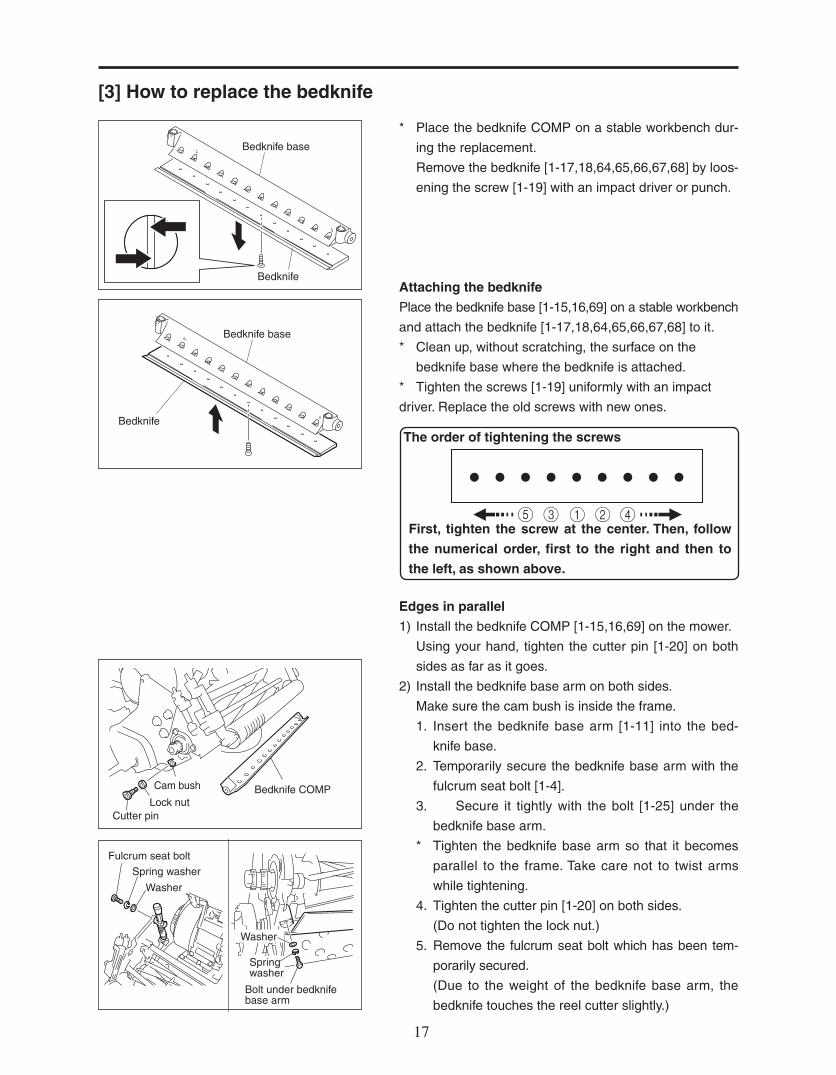
* Place the bedknife COMP on a stable workbench dur-
ing the replacement.
Remove the bedknife [1-17,18,64,65,66,67,68] by loos-
ening the screw [1-19] with an impact driver or punch.
Attaching the bedknife
Place the bedknife base [1-15,16,69] on a stable workbench
and attach the bedknife [1-17,18,64,65,66,67,68] to it.
* Clean up, without scratching, the surface on the
bedknife base where the bedknife is attached.
* Tighten the screws [1-19] uniformly with an impact
driver. Replace the old screws with new ones.
Edges in parallel
1) Install the bedknife COMP [1-15,16,69] on the mower.
Using your hand, tighten the cutter pin [1-20] on both
sides as far as it goes.
2) Install the bedknife base arm on both sides.
Make sure the cam bush is inside the frame.
1. Insert the bedknife base arm [1-11] into the bed-
knife base.
2. Temporarily secure the bedknife base arm with the
fulcrum seat bolt [1-4].
3. Secure it tightly with the bolt [1-25] under the
bedknife base arm.
* Tighten the bedknife base arm so that it becomes
parallel to the frame. Take care not to twist arms
while tightening.
4. Tighten the cutter pin [1-20] on both sides.
(Do not tighten the lock nut.)
5. Remove the fulcrum seat bolt which has been tem-
porarily secured.
(Due to the weight of the bedknife base arm, the
bedknife touches the reel cutter slightly.)
[3] How to replace the bedknife
Bedknife base
Bedknife
Bedknife
Bedknife base
Cam bush Bedknife COMPLock nut
Cutter pin
Fulcrum seat bolt
Spring washer
Spring washer
Washer
Washer
Bolt under bedknife base arm
The order of tightening the screws
First, tighten the screw at the center. Then, follow
the numerical order, first to the right and then to
the left, as shown above.

1818 19
3) Align the punch mark of the cam bush on both sides to
the mowing direction.
4) Make sure that the reel cutter and bedknife contact.
5) Try to cut a strip of newspaper from left to right while
gently turning the reel (at 5 to 6 different places)
* If the reel and bedknife are not yet engaged correctly.
(Do not turn the reel blade too fast as it is dangerous)
6) Adjust the position of the cam bush [1-22] so that a
newspaper is cut smoothly at both ends of the reel.
* When cutting a newspaper, insert it vertically to the
bedknife. Turn the reel cutter slowly and adjust appro-
priately so that the newspaper is cut sharply.
7) Once the position of the cam bush is adjusted, mark
the position of the punch mark on the mower with a
marker.
0.3Punch mark
Center of cutter pin
Center of cam bush
Bedknifegoes down
Bedknifegoes up
Reel cutter
Bedknife
No clearance
Clearance
Reel cutter
Bedknife
Punch mark
1818 19
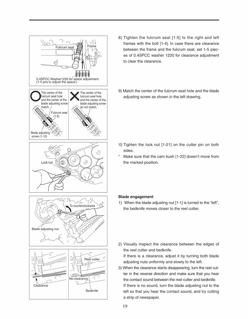
8) Tighten the fulcrum seat [1-5] to the right and left
frames with the bolt [1-4]. In case there are clearance
between the frame and the fulcrum seat, set 1-5 piec-
es of 0.4SPCC washer 1220 for clearance adjustment
to clear the clearance.
9) Match the center of the fulcrum seat hole and the blade
adjusting screw as shown in the left drawing.
Lock nut
To counterclockwise
Blade adjusting nut
No-clearance
Clearance
Reel cutter
Bedknife
The center of thefulcrum seat holeand the center of theblade adjusting screwmatch.
The center of thefulcrum seat holeand the center of theblade adjusting screwdo not match.
Fulcrum seat (1-5)
Blade adjusting screw (1-12)
10) Tighten the lock nut [1-21] on the cutter pin on both
sides.
* Make sure that the cam bush [1-22] doesn’t move from
the marked position.
Blade engagement
1) When the blade adjusting nut [1-1] is turned to the “left”,
the bedknife moves closer to the reel cutter.
2) Visually inspect the clearance between the edges of
the reel cutter and bedknife.
If there is a clearance, adjust it by turning both blade
adjusting nuts uniformly and slowly to the left.
3) When the clearance starts disappearing, turn the reel cut-
ter in the reverse direction and make sure that you hear
the contact sound between the reel cutter and bedknife.
If there is no sound, turn the blade adjusting nut to the
left so that you hear the contact sound, and try cutting
a strip of newspaper.
FrameFulcrum seat
0.4SPCC Washer1220 for space adjustment.(1-5 pcs to adjust the space.)

2020 21
5) Apply grease on the 33-tooth reel gear and 42-tooth
reel gear [1-46] , 36-tooth reel gear and 45-tooth reel
gear [6-54] and the lip surface of the oil seal on both
sides of the cover. Attach the left cover [6-89] as shown
in the illustration.
6) Secure the left cover [6-89] with the six bolts [6-2], one
bolt [6-94], six bolts [6-30].
* Please tighten the screws uniformly.
7) Attach the 10 special bolt 35 [1-47].
(Lock the reel by inserting a wooden hammer handle
into the reel cutter to prevent the reel from turning.)
Left cover
Bolt [6-94]
Bolt [6-30] Bolt [6-2]
Reel cutter
10 special bolt 35
Reel cutter
Blade
4) To make sure that the newspaper is cut uniformly on
both sides of the cutter, loosen the blade adjusting nut
on the side where the newspaper is cut better by turn-
ing it slightly to “right” and adjust the side that doesn’t
cut well by turning the nut slightly to “left”.
* Be careful not to press the cutter and blade to each
other too hard.

2020 21
Equipped with the groomer
1) Apply the grease (EXCELITE EP No.2) to the 20-tooth
reel gear [8-46].
Apply the grease also to the vertical gear case’s O-ring
[8-48].
(Make sure that the O-ring is firmly fitted into the groove.)
2) Fit the vertical gear case over the 20-tooth reel gear
[8-46]. (Push the case in the direction of as far as
possible.)
On the opposite side, fit the left vertical housing [8-63]
into the frame’s groove, and raise the groomer.
3) Insert the right and left square-root bolts [8-49] along
the groove from the inside of the frame.
Insert the adjusting screw 108 [8-57] and secure it
temporarily with the spring washer [8-59] and tall nut
[8-58].
4) Attach the right case locking bolt [8-60]. (This bolt is for
keeping the case from unfastening, not for locking it
down.)
* Be careful not to tighten the bolt too hard.
5) Tighten the tall nut [8-58] on the adjusting screw on
both sides.
O-ring
Vertical gear case
Groomer
Square-root bolt Tall nut
Square-root bolt
Left vertical housing
Adjusting screw
1.6 compression spring13.720
2C5191P washer 8.522
Right case locking bolt
6S washer6 bolt 10
Clutch retainerspring 5
H/L change lever
8) Install the H/L change lever [6-91] on the left cover
[6-89], attach the clutch retainer spring 5 [6-56], 6S
washer, 6 bolt 10.
* Install the alignment finger of H/L change lever in the
33-tooth reel gear and 42-tooth reel gear.

2222 23
1) Set the reel cover into the groove behind the bedknife
base.
2) Secure it with the two bolts [1-25].
Bolt x 2 (left & right)
Reel cover Reel cover
Bedknife base
Bolt
[4] Installation of the reel cover
Cover
Models not equipped with a groomer
Attach the cover.
* After making sure that the position of the O-ring [1-31]
is correct, apply grease to it. Secure it tightly.

2222 23
1) Set up the stand and remove the traveling wheels.
First, loosen the hexagon socket head bolt on the
wheel driving fitting, and then remove the fitting.
Remove the key [4-11] from the outer drum shaft.
Use an item such as a wooden hammer handle to pre-
vent the reel from turning, and remove the 10 special
bolt 35 [1-47], H/L change lever [6-91]. Then, unscrew
the six bolts [6-2], six bolts [6-30], one bolt [6-94], and
then detach the left cover [6-89]
* Do not force open the cover using an object such as a
screwdriver as it will scratch the adjoining surfaces.
If the cover doesn’t come off easily, remove it by tap-
ping those six locations (indicated by the arrows in the
left illustration) lightly with a wooden hammer.
2) Remove the stop ring [6-21], washer [6-22,23], bearing
[6-24] and collar [6-25] from the outer drum shaft.
* If you mark the gears with numbers as shown in the
illustration using a permanent marker before you re-
move them, it helps to make the direction and order of
the gears clear when assembling them.
Remove the gears in the order of the numbers shown
in the illustration.
(When removing the #2 gear, be careful not to lose the
key.)
(Remove the changeover clutch lever before the #7
gear.)
3) Pay attention to the quantity, size, direction, and type
when removing the gear, washer, bearing, and needle
bearing.
* Check for any crack on the gear or wear on the bear-
ing and shaft, and if necessary, replace them.
4) Assemble the corresponding parts in the reverse order
that they were disassembled.
[5] Overhaul of the inside of the gear case (left)
Washer
Bearing
Bearing
Collar
Stop ring
Wheel driving fitting
8 Hexagon socket head bolt 25
Left cover
Bolt [6-2]Bolt [6-30]
Bolt [6-94]
Bolt [6-94]
Bolt [6-30] Bolt [6-2]

2424 25
* Make sure that the changeover clutch lever is fitted
tightly into the groove of the #7 gear.
Apply enough grease to the gear tooth surface and
bearings when assembling them.
5) Before attaching the cover, verify the gears’ movement
and the number of the washers. If the cover doesn’t
fit well, the direction of the gears may be wrong or the
gears may not be fitted well.
* Please refer to the Parts Catalog as well.
* Please do not force the cover to fit by hitting on it. Such
actions could cause a fracture or dent.
* When tightening the bolts on the cover, first tighten
them by hand, and then using a tool, tighten them grad-
ually in a diagonal order (over a couple of rounds).
After the bolts are tightened, turn the drum by hand to
see if it turns smoothly.
#7 gearChangeover clutch lever

2424 25
1) Set up the stand and remove the traveling wheels.
First, loosen the hexagon socket head bolt [4-10] on
the wheel driving fitting, and then remove the fitting.
Remove the key [4-11] from the outer drum shaft.
Unscrew the six bolts [6-2] and remove the right cover
[6-3].
* Use a permanent marker to mark the gears with num-
bers as shown in the illustration before you remove
them. This helps clarify the direction and order of the
gears when reassembling them.
2) Remove the stop ring [6-21], washer [6-22,23], bearing
[6-24], and collar [6-25] from the outer drum shaft.
Remove the gears in the order of the numbers shown
in the illustration.
(When removing the #2 gear, be careful not to lose the
key.)
Pay attention to the quantity, size, direction, and type
when removing the gear, washer, bearing, and needle
bearing.
Check for any crack on the gear or wear on the bear-
ing and shaft, and if necessary, replace them.
3) Assemble the corresponding parts in the reverse order
that they were disassembled.
* When assembling them, apply enough grease to the
gear tooth surface and bearings.
[6] Overhaul of the inside of the gear case (right)
Hexagon sockethead bolt
Wheel driving fitting Key
Stop ring
Washer
Bearing
Collar

2626 27
1) Set up the stand and remove the traveling wheels.
Remove the left cover [6-89].
* For more information, refer to sections “ [5] Overhaul
of the inside of the gear case (left)” or “ [6] Overhaul of
the inside of the gear case (right)”.
2) Remove the #1 and #2 gears.
3) Remove the right cover [6-3].
4) Remove the #1 and #2 gears.
5) Remove both the right and left packings.
(Be careful not to break the packings when removing
them. If they ever break, exchange them with the new
ones.)
Unscrew the three bolts [6-28] from both the right and
left drum housings.
[7] Removing / installing the drum assembly
Left cover
Bolt [6-2]Bolt [6-30]
Bolt [6-94]
Hexagon socket head bolt
Wheel driving fitting Key
Collar
Stop ring
Bearing
Washer
Bolt [6-28]
Packing
Packing
Washer
Bearing
Bearing
Collar
Stop ring

2626 27
6) Gently hold both ends of the drum shaft with panto-
graph jacks.
(If no pantograph jack is available, use an alterna-
tive and make sure that the drum shaft doesn’t come
down.)
7) Remove the right and left drum housings [6-29] out-
ward.
* If they don’t come off, remove them by tightening all-
screw bolts (M8 x 40 or larger) into the two female
screws.
After both drum housings come off, remove the right
and left jacks, and take the drum Ass’y down.
8) Lift up the handle and stand, and move the mower for-
ward.
* After moving the mower, set up the stand.
9) Assemble the corresponding parts in the reverse order
that they were disassembled.
* When assembling them, apply enough grease to the
gear tooth surface and bearings.
When installing the drum housing, apply a silicon gas-
ket to the locations that touch the frame.
1. Clean up the old gasket and any dirt attached to the
frame. (Remove grease.)
2. Apply a liquefied gasket to the packing’s surface
facing the frame (be careful not to use too much
grease), and attach the packing to the frame.
* Replace the packings as needed.
Drum shaft
If the drum housing doesn't comeoff, remove it by tightening the twoall-screw bolts (M8 x 40 or larger).
Drumhousing
Drumhousing
: The area to apply a liquefied gasket
Drum shaft
Set up the stand

2828 29
Oil seal Oil seal
1) Remove the outer drum shaft [4-15] by unscrewing the
four bolts [4-16] on each side.
* Secure the drum so that it doesn’t turn when loosening
the bolts.
2) Remove the stop rings [4-17] on both sides.
Separate the right from the left drum, and remove one
of them.
* If an adjustment shim is used, be careful not to lose it.
3) Pull out the intermediate drum shaft [4-24,34,40].
* Be careful not to lose the drum center collar.
4) Tap inside the drum using something like a round bar,
and remove the oil seal and bearing .
* If an adjustment shim is used, be careful not to lose it.
Outer drum shaft
Stop ring
Intermediate drumshaft
Drum center collar
Oil sealBearing
[8] Disassembling / assembling the drum
2828 29
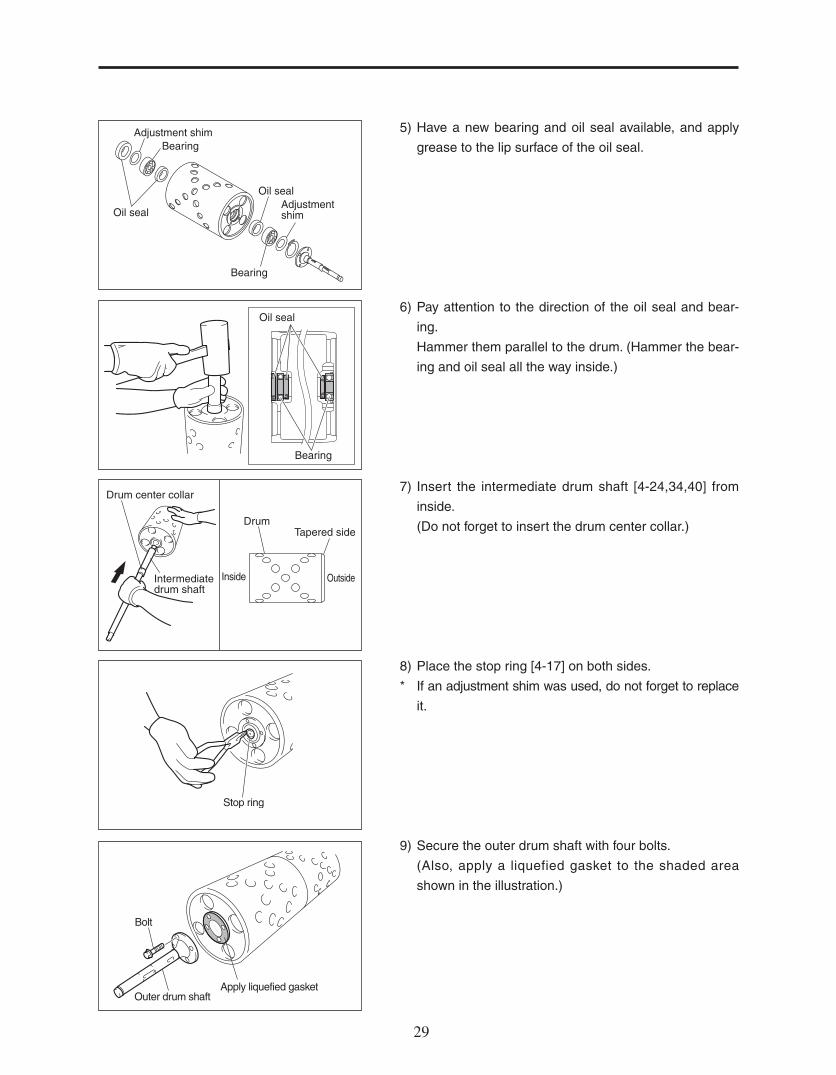
5) Have a new bearing and oil seal available, and apply
grease to the lip surface of the oil seal.
6) Pay attention to the direction of the oil seal and bear-
ing.
Hammer them parallel to the drum. (Hammer the bear-
ing and oil seal all the way inside.)
7) Insert the intermediate drum shaft [4-24,34,40] from
inside.
(Do not forget to insert the drum center collar.)
8) Place the stop ring [4-17] on both sides.
* If an adjustment shim was used, do not forget to replace
it.
9) Secure the outer drum shaft with four bolts.
(Also, apply a liquefied gasket to the shaded area
shown in the illustration.)
Bearing
Bearing
Oil seal
Oil seal
Adjustment shim
Adjustment shim
Oil seal
Bearing
Drum center collar
Intermediatedrum shaft
DrumTapered side
Inside Outside
Stop ring
Apply liquefied gasket
Bolt
Outer drum shaft

3030 31
Clutch cover receiver
Bolt
Left cover
Bolt [6-2]Bolt [6-30]
Bolt [6-94]
Hexagon socket head bolt
Wheel driving fitting Key
[9] Removing / installing / disassembling / assembling the transmission shaft
1) Set up the stand first, and then remove the traveling
wheels on both sides.
2) Open the clutch cover and remove the clutch cover re-
ceiver [5-43,44,53].
(Remove the two bolts.)
3) Remove the six bolts [6-2], six bolts [6-30], one bolt
[6-94], and remove the left cover [6-89].
* Refer to Section “ [5] Overhaul of the inside of the gear
case (left).”
4) Remove the #1 gear [6-19].
Remove the #6 gear [6-67].
5) Remove the right cover [6-3]. (Remove the six bolts.)
Traveling wheel
Stand

3030 31
Needle roller
Collar
Right transmissionshaft Stop ring
Needle roller
6) Remove the nut [6-6] from the #3 gear. (left-hand
threaded)
Loosen the nut while holding the #1 gear with a flat-
head screwdriver to keep the #3 gear from turning.
(Hold the flathead screwdriver vertical to the teeth of
the #1 gear.)
7) Remove the #3 gear by turning it clockwise.
* They are left-hand threaded.
Remove the #1 gear.
8) Keep the right transmission shaft [6-13] from turning
by using something like pliers, and remove the #3 gear
by turning it clockwise.
Remove the stop ring [6-34] on the right side first.
Move the differential joint shaft collar [6-33] slightly and
remove the needle roller [6-35].
9) Remove the stop ring [6-34] on the left side, and then
slightly move the differential joint shaft collar [6-33].
Pull out the needle roller [6-35], and then remove the
stop ring [6-34].
Washer
Disc spring
Nut
Loosen Bearing
Collar
Stop ring
Bearing
Washer
Needle roller
Collar
Stop ring

3232 33
Right transmission shaft
Right frame side
Collar (right frame side)
Stop ring (right frame side)
Collar (left frame side)
Stop ring (left frame side)
Left frame side
10) Remove the 16-tooth right differential gear [6-66].
11) First pull out the transmission shaft [6-36,80,101] in
the direction of (as shown in the illustration).
* Be careful not to lose the collar [6-33] or stop ring [6-34]
that are attached to the transmission shaft.
12) Pull out the right transmission shaft.
(If you can’t pull it out by hand, remove it by tapping it
lightly with a wooden hammer.)
* Check for any wear and damage on the oil seal, bear-
ing, and shaft, and if necessary, replace them.
When replacing them, pay attention to their direction
and order.
13) Assemble the corresponding parts in the reverse order
that they were disassembled.
* Pre-install the three stop rings [6-34] and two col-
lars [6-33] on the transmission shaft [6-36,80,101] as
shown in the illustration.
14) Make sure that the 50-tooth differential gear Ass’y [6-
67] and the differential gear shaft receiver [6-65] fit to-
gether without any gap.
Transmission shaft
Collar
Stop ring
50-tooth differential gear Ass'y
Differential gear shaft receiver

3232 33
Screwdriver
15) Tighten the gear by turning it all the way to the left, and
then turn it back to the right a quarter of a circle. (left-
hand threaded)
Then, secure it with the lock nut [6-6].
* To avoid overstretching the transmission shaft, loosen
it slightly.

3434 35
1) Fold the stand and let the drum touch the ground.
2) Set the changeover clutch lever to “Reel ON” position.
Hold a flathead screwdriver against the 51-tooth gear
[6-85] to keep it from turning, and then remove the nut
from the 16-tooth [5-39].
Remove the disc spr ing washer and detach the
16-tooth gear [5-39] and 1 shaft collar [5-38].
3) Unscrew the four bolts [5-18] and remove the clutch
box [5-16].
4) Remove the four bolts [7-1] from the engine.
* Do not remove the four bolts [7-4] from the engine
base.
5) Remove the engine.
* Be careful with the throttle wire and the engine stop
cord that are still attached to the engine.
[10] Disassembling / assembling / adjusting the engine clutch area
16-tooth gear51-tooth gear
HorizontalStand
Clutch box
Bolts at engine base
Engine
Throttle wireEngine
Engine switch code

3434 35
6) Pull out the clutch shaft Ass’y.
7) Secure the clutch shaft Ass’y [5-24,25,51] on a vice.
Pull out the tapered pin [5-27] using a pin remover.
* When securing the clutch shaft Ass’y on a vice, wrap it
with a waste cloth to avoid scratching the surface.
* Since the pin is tapered, remove it by tapping on the
thinner end.
* When reassembling it, pay attention to the direction of
the pin.
8) First, remove the facing holder [5-26], and then remove
the spring [5-30] and clutch facing [5-31].
* When replacing the facing, make sure the direction is
correct.
9) Assemble the corresponding parts in the reverse order
that they were disassembled. (up to assembly of the
engine)
* Make sure to insert the tapered pin in the right direc-
tion.
When inserting the pin, the end with a smaller diam-
eter goes in first. (The hole is tapered as well.)
10) Install the clutch shaft Ass’y [5-24,25,51] to the left
frame.
Clutch shaftAss'y
Tapered pin
Waste cloth
Pin remover
Clutch facing
Spring
Facing holder
Pay attention to the direction of the groove
Note the directionEnd with bigger diameterEnd with smaller diameter
Clutch facing
Tapered pin
Clutch shaft Ass'y

3636 37
11) Install in the following order: the collar [5-38], gear [5-
39], washer [5-40], disc spring washer [5-41], and nut
[5-42].
When tightening the nut, hold a flathead screwdriver
against the gear A (51-tooth gear) to keep it from turn-
ing.
12) When installing the engine, fit the facing in the groove
of the engine clutch, and secure the engine temporar-
ily with the four bolts [7-1].
* Of the four bolts, tighten the two which are on a diago-
nal line until the spring washer levels out.
13) Secure the clutch box [5-16] with the four bolts [5-18].
* Set the main clutch lever of the handle to “ON” posi-
tion.
14) Using the 0.5mm (0.020 in.) thickness gauge (included
with this product), adjust the clearance (at 6 locations)
between the engine clutch and the clutch facing to 0.5
- 1.00mm (0.20 – 0.40in.) by hammering lightly with a
tool such as a plastic hammer (in the direction of the
arrows as shown in the illustration).
* Once the gap is adjusted to be parallel, securely tight-
en the four bolts on the engine.
Move the main clutch lever and check for movement
and clearance.
15) Shift the main clutch to ON and OFF repeatedly, and
adjust the clutch wire adjusting nut so that the opera-
tion distance is 1.30 - 1.50mm (0.52 – 0.60in.).
Make sure the main clutch successfully turns off when
shifted to OFF.
Clearance0.5~1.0mm
Engine clutch
A (51-tooth gear)
16-tooth gear
Disc springWasher
Collar16-tooth gear
Nut
Clutch box
Engine clutch
Facing
Clutch wire adjusting nut
Clutch facingOperation distance: 1.3~1.5mmEngine clutch
3636 37
[11] Disassembling / assembling / adjusting the brake
Wire mounting bracketBrake Ass'y
Brake shoe
Brake shoe
Sandpaper
Bring downA
A
AB
B
B
Wire mounting bracketBrake Ass'y
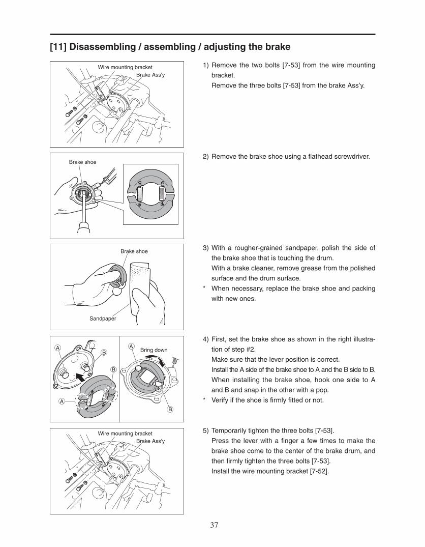
1) Remove the two bolts [7-53] from the wire mounting
bracket.
Remove the three bolts [7-53] from the brake Ass’y.
2) Remove the brake shoe using a flathead screwdriver.
3) With a rougher-grained sandpaper, polish the side of
the brake shoe that is touching the drum.
With a brake cleaner, remove grease from the polished
surface and the drum surface.
* When necessary, replace the brake shoe and packing
with new ones.
4) First, set the brake shoe as shown in the right illustra-
tion of step #2.
Make sure that the lever position is correct.
Install the A side of the brake shoe to A and the B side to B.
When installing the brake shoe, hook one side to A
and B and snap in the other with a pop.
* Verify if the shoe is firmly fitted or not.
5) Temporarily tighten the three bolts [7-53].
Press the lever with a finger a few times to make the
brake shoe come to the center of the brake drum, and
then firmly tighten the three bolts [7-53].
Install the wire mounting bracket [7-52].

3838 39
6) Make sure the brake works by gripping the brake lever.
(If the brake doesn’t work, adjust it by tightening the
adjusting nut of the brake wire.)
* Set the brake shoe so that it does not always touch the
brake drum. (Avoid the brake always being engaged.)
The brake may be engaged if, when rotating the drum
wheel, you hear a rubbing sound or the drum feels
heavy.
Adjusting nut

3838 39
1) Remove the tall nut [2-1], disc spring washer [2-2],
washer [2-3], and square-root bolt [2-7] from the left
roller bracket on the left frame.
2) First loosen the lock nut [2-26] on the right bracket
and then the stopper bolt [2-25].
3) Remove the 15 extension pin 19 [2-5] while supporting
the front roller [2-9,10].
4) Remove the front roller [2-9,10] from the main unit.
Do not lose the washer between the front roller and
bracket.
5) Remove left hard thread roller bolt.
(Part # K0071000152)
6) First loosen the lock nut [2-26] and stopper bolt [2-25],
and remove the roller bracket [2-24] on the left frame
by tapping it with a wooden hammer.
[12] Disassembling / assembling the front roller (with a groomer) (As for the “with smooth front roller” and “with independent arm” types, follow the same steps )
Square-root boltWasher
Disc spring Tall nut
Stopper bolt
Lock nut
15 extension pin 19
WasherFront roller
Left hard thread roller bolt
Stopper boltLock nut
Roller bracket

4040 41
7) Remove the oil seal [2-12] on both sides using a flat-
head screwdriver.
Remove the stop ring [2-13].
8) Remove the front roller shaft by tapping the end which
is sticking out more.
9) Secure the removed front roller shaft on a vice, and
remove the bearing [2-14,15] from the shaft using a
pulley remover.
10) Remove the bearing on the opposite side by tapping
the removed roller shaft into it.
Oil seal
Stop ring
WasherBearing + seal
Stop ringOil seal
Front roller shaft
Gear pullerBearing
Bearing
Roller shaft
Roller shaft

4040 41
Preparation of replacement parts
Have the replacement parts ready beforehand.
1) Apply some grease inside the oil seal [2-14]. Insert the
bearing [2-15] into the oil seal firmly by tapping it with
a wooden hammer.
2) Apply grease to the lip surface of the oil seal [2-12]
which is to be set on the outside of the roller. (The lip
surface is inside the oil seal as shown in the illustra-
tion.)
Have a stop ring [2-13] and washer [2-16] available.
* Inspect each part (such as the roller shaft), and re-
place them when needed.
3) Pound in the combined set of the bearing [2-15] and oil
seal [2-14] on one side of the roller.
(The oil seal side should face upward.)
Bearing
BearingOil sealOil seal
Drivingtool
Oilseal
Oil seal
Bearing
Oil seal
Grease
WasherBearing + seal
Stop ringOil seal

4242 43
Using a driving tool, pound in the bearing and oil seal set
all the way.
(Drive them in below the stop ring’s groove.)
4) Insert the stop ring [2-13].
5) Pound in the oil seal [2-12] on the outside. (up to the
edge of the roller)
6) Insert the washer from the end of the roller shaft that
has a shorter stepped section.
Insert the shaft from the end of the roller with no bear-
ing.
Place the roller shaft firmly into the bearing.
7) After the shaft is inserted, turn the roller upside down
and insert the washer [2-16] from the other end of the
shaft.
Additionally, using a driving tool, hammer in the bear-
ing [2-15] and oil seal [2-14] set, stop ring [2-13], and
oil seal [2-12], in this order .
Stop ring
Oil seal
Roller shaft (shorter end)
Washer
Washer
Stop ring's groove
Combined set ofbearing and oil seal

4242 43
8) Install the washer [2-8] and bracket [2-24] as shown in
the illustration.
Set and secure the flat end of the roller shaft into the
stopper bolt side, and lock it.Stopper bolt
WasherLock nut
Washer Front rollerSet in
15 extension pin 19
Drivingtool
Oilseal
9) As shown in the illustration, match the bracket to the
frame’s joint, and set the top of the bracket in the
groove of the roller adjuster [2-21].
10) Insert the washer [2-8] between the roller and bracket
[2-23], and install them with the 15 extension pin19.
(Make sure that the extension pin does not cut into the
washer.)
Stopper bolt
Lock nut
11) Tighten the bracket’s stopper bolt [2-25] and secure it
with the lock nut [2-26].
4444 45
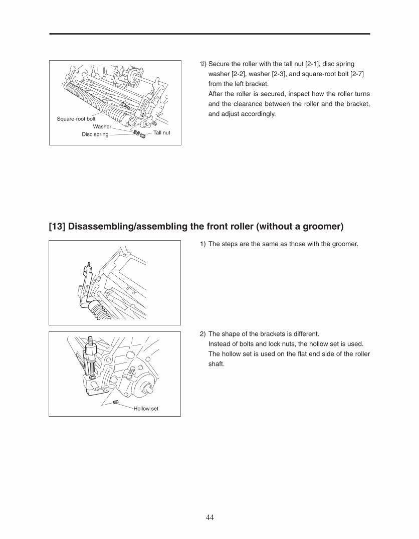
1) The steps are the same as those with the groomer.
2) The shape of the brackets is different.
Instead of bolts and lock nuts, the hollow set is used.
The hollow set is used on the flat end side of the roller
shaft.
[13] Disassembling/assembling the front roller (without a groomer)
Hollow set
Square-root boltWasher
Disc spring Tall nut
12) Secure the roller with the tall nut [2-1], disc spring
washer [2-2], washer [2-3], and square-root bolt [2-7]
from the left bracket.
After the roller is secured, inspect how the roller turns
and the clearance between the roller and the bracket,
and adjust accordingly.

4444 45
6 bolt 10
6S washer
6 washer
Clutch retainer spring
Clutch lever
1) Refer to #1 of Equipped with the groomer on page 8
for removing the front groomer from the main unit.
Left vertical housing
2) Remove the left vertical housing [8-63].
3) Pay attention to the direction of the oil seal [8-27].
Disassemble, assemble, adjust, and replace.
Before assembling them, apply grease to the lip sur-
face of the oil seal.
4) Remove the clutch retainer spring [8-8].
5) Remove the clutch lever [8-9].
[14] Disassembling / assembling / adjusting the front groomer
Left vertical housing
Left vertical housing
Bearing 69022RS
Stopper 30
Oil seal MHSA15257
Stop ring R28
Oil seal
Bearing

4646 47
6) Unscrew the four bolts [8-14,15] from the gear case
cover, and then remove the cover [8-12].
7) Remove the 20-tooth vertical gear [8-30].
* Lock the nut [8-76] on the groomer using a screw
wrench, and remove the nut [8-29](left-hand threaded)
which secures the 20-tooth vertical gear.
8) Pay attention to the order and direction of the oil seal
[8-16] and bearing [8-34].
9) Replace other parts when necessary.
Pay attention to the parts (such as gear) which need to
be set in a certain direction.
20-tooth vertical gear
CollarScrew wrench
Washer
20-tooth vertical gearNut
Cover
10 left-hand thread nut P110 disc spring washer
20-tooth vertical gear12.1STKM collar 176
Stop ring R24
Bearing6901RDC3
16011 washer
12.1STKM collar 1714
Oil seal MHSA15227
Collar
Oil seal
Seal Seal
Bearing
Caseside
Groomerside

4646 47
Punch mark
Collar
Rotate the hexagonend by one side eachtime
Dethatching blade
[15] Setting of dethatching blades
10) Loosen the lock nut [8-72] and then the hollow set [8-
71].
11) Secure the 17 special nut (Groomer Blade Locking
nut) [8-76] on the spine side using a screw wrench, re-
move the 17 special nut (Groomer Blade Locking nut)
[8-76] on the opposite side first, and then remove the
groomer’s collar and blade.
Hollow setLock nut
17 special nut Collar Blade
1) Make sure that the 17 special nut (Groomer Blade
Locking nut) [8-76] is attached on the spline side of the
vertical shaft.
If it is attached, stand the shaft with the spline side on
the bottom.
2) First, insert the two collars [8-22], and then continue in
the order of one dethatching blade [8-23], one collar,
one dethatching blade, and one collar. Insert the two
collars at the end.
* Position the punch mark on the dethatching blade fac-
ing you, and insert the blade by rotating the vertical
shaft [8-20,21,79] clockwise.
Rotate the vertical shaft’s hexagon end by one sixth of
a turn each time you insert one blade. (Always position
the punch mark facing you.)
Match the helical angle of the dethatching blade with
that of the reel blade.

4848 49
SpacerSpacer
Front roller
17 special nut
Dethatchingblade
[16] Adjusting the front groomer
3) Finally, insert the 17 special nut (Groomer Blade Lock-
ing nut) [8-76], secure it with the hollow set [8-71], and
lock it with the lock nut [8-72].
* Please do not tightened to much power.
(Torque = 5~10 N m)
4) Install it in the vertical gear case [8-47] in the reverse
order that it was disassembled.
* Apply enough grease to the gear’s tooth surface and
the needle bearings before installing the cover.(Refer
to the Parts Catalog.)
5) Install the left vertical housing [8-63].
* Please refer to #1 ~ #5 of Equipped with the groom-
er section on page 21 for installing the dethatching
blades to the main unit.
After the front groomer is installed on the main unit, make
sure that the two dethatching blades go into each groove
on the front roller.
* When adjusting the groomer to the front roller, first
start by adjusting with the 17 special nut [8-76] first. If
this does not give you the required clearances, then
use the spacers [8-24] provided to every space the
blades between the groomers on the roller.

4848 49
[17] Disassembling/assembling the IGCA roller
1) Remove the washer [13-10], shaft [13-11], and snap
pin [13-12] from the rear frame stay[7-92].
2) Raise the catcher arm and remove it from the mower.
3) Unfasten the bolts [13-15] of both side of the catcher
arm. To prevent roller shaft from spinning, slide a screw
driver through the hole of the roller shaft and hold for
support while loosening bolt. Repeat for both sides.
Rear frame stay
Snap pin
Shaft
Washer
Catcher arm
Bolt

5050 51
4) Remove the oil seal [13-22] on both sides using a flat-
head screwdriver.
Remove the stop ring [13-21].
5) Remove the front roller shaft by tapping the end which
is sticking out more.
6) Secure the removed front roller shaft on a vice, and
remove the bearing [13-19,20] from the shaft using a
pulley remover.
7) Remove the bearing on the opposite side by tapping
the removed roller shaft into it.
Gear pullerBearing
Oil seal
Stop ring
Front roller shaft
Bearing
Roller shaft
Roller shaft
WasherBearing + seal
Stop ringOil seal

5050 51
Preparation of replacement parts
Have the replacement parts ready beforehand.
1) Apply some grease inside the oil seal [13-20]. Insert
the bearing [13-19] into the oil seal firmly by tapping it
with a wooden hammer.
2) Apply grease to the lip surface of the oil seal [13-22]
which is to be set on the outside of the roller. (The lip
surface is inside the oil seal as shown in the illustra-
tion.)
Have a stop ring [13-21] and washer [13-18] available.
* Inspect each part (such as the roller shaft), and re-
place them when needed.
3) Pound in the combined set of the bearing [13-19] and
oil seal [13-20] on one side of the roller.
(The oil seal side should face upward.)
Bearing
BearingOil sealOil seal
Oil seal
Bearing
Oil seal
Grease
WasherBearing + seal
Stop ringOil seal
Drivingtool
Oilseal

5252 53
Using a driving tool, pound in the bearing and oil seal set
all the way.
(Drive them in below the stop ring’s groove.)
4) Insert the stop ring [13-21].
5) Pound in the oil seal [13-22] on the outside. (up to the
edge of the roller)
6) Insert the washer from the end of the roller shaft.
Insert the shaft from the end of the roller with no bear-
ing.
Place the roller shaft firmly into the bearing.
7) After the shaft is inserted, turn the roller upside down
and insert the washer [13-18] from the other end of the
shaft.
Additionally, using a driving tool, hammer in the bear-
ing [13-19] and oil seal [13-20] set, stop ring [13-21],
and oil seal [13-22], in this order .
Stop ring's groove
Combined set ofbearing and oil seal
Stop ring
Oil seal
Washer
Washer

5252 53
8) Screw bolt [13-15] and s washer [13-16] through hole
on catcher arm [13-3] and into roller shaft [13-17]. Re-
peat for both sides.
9) Tighten and lock bolt [13-15]. To prevent roller shaft
[13-17] from spinning, slide a screw driver through the
hole of the roller shaft and hold for support while tight-
ening bolt [13-15].
10) From the front of the greens mower, drop the catcher
arm into the right position.
11) Slide washer [13-11] over protruding end of the shaft
[13-10], then lock it into the right place with snap pin
[13-12].
Drivingtool
Oilseal
S washer
Bolt
Catcher arm
Roller shaft
Catcher arm
Bolt
Roller shaft
Rear frame stay
Snap pin
Shaft
Washer

5454 55
[18] Ajusting the arm stopper
1) Adjust distance of catcher arm [13-3] by tightening or
loosening arm stoppers [13-5].
Recommended space between the arm stopper and
stopper brackets [13-6,8] should be 1 mm, when the
front roller [3-37] is parallel with the roller [13-23] of
catcher arm.
2) Lock the arm stopper [13-5] into desired position by
tightening and loosening the nuts [13-4] on both sides.
Stopper bracket
Arm stopper
Catcher arm
Arm stopper
Nut
Arm stopper

5454 55
[19] Reference
Bl
Bl Black
Bu Blue
W White
Bl
Bl
Bu
W o
r Bu
W
(1)
(2) (3)
(1) ENGINE SWITCH
(2) SPARK PLUG
(3) IGNITION COIL
(4)
(5)
(6)
(4) COIL ASSY., LAMP
(5) HEADLIGHT SWITCH
(6) HEADLIGHT
Wiring Diagrams (GX120)

56

LM56GA--SM--USZ/09M-00-SPEC