Embed Size (px)
Citation preview

HDMI Coaxial Cable Extender
COS-100HD-B Users Guide
Ver.1.5.0
RS
-23
2C
L AU
DIO
INP
UT
R
Tx
1 COAX Tx for HDMI COS-T100HD-B
FG
DC
5V
3A
HD
MI
OU
TP
UT
HD
MI
INP
UT
POWERSTATUS
LINK KEY LOCK
-+SET
SIGNAL HDCP RS
-23
2C
FG
DC
5V
3A
HD
MI
Rx
COS-R100HD-B
LA
UD
IO O
UT
PU
TR
POWERSTATUS
LINK KEY LOCK
-+SET
SIGNAL HDCP
OU
TP
UT
INP
UT
1 COAX Rx for HDMI
OU
TP
UT
● Thank you for choosing our product.
● To ensure the best performance of this product, please read this User’s Guide fully and carefully before
using it and keep this manual together with the product for reference as needed.
IDK Corporation

COS-100HD-B User’s Guide
2
Trademarks
Blu-ray Disc and Blu-ray are trademarks of Blu-ray Disc Association. The terms HDMI and HDMI High-Definition Multimedia Interface, and the HDMI Logo are trademarks or
registered trademarks of HDMI Licensing Administrator, Inc. in the United States and other countries. Connection Reset is a registered trademark of IDK Corporation in Japan.
All other company and product names mentioned in this manual are either registered trademarks or
trademarks of their respective owners. In this manual, the “®” or “™” marks may not be specified.

COS-100HD-B User’s Guide
3
Before reading this manual
● All rights reserved.
● Some of the contents in this user’s guide such as the appearance of diagrams, menu operations,
communication commands, and so on may differ between products depending on the specific version.
● This Users guide is subject to change without notice. You can download the latest version from IDK’s
website at: http://www.idkav.com
FCC STATEMENT This equipment has been tested and found to comply with the limits for a Class A digital device, pursuant to part 15 of the FCC Rules. These limits are designed to provide reasonable protection against harmful interference when the equipment is operated in a commercial environment. This equipment generates, uses, and can radiate radio frequency energy and, if not installed and used in accordance with the instruction manual, may cause harmful interference to radio communications. Operation of this equipment in a residential area is likely to cause harmful interference, in which case the user will be required to correct the interference at their own expense.
CE MARKING
This equipment complies with the essential requirements of the relevant European health, safety and
environmental protection legislation.
WEEE MARKING Waste Electrical and Electronic Equipment (WEEE), Directive 2002/96/EC
(This directive is only valid in the EU.) This equipment complies with the WEEE Directive (2002/96/EC) marking requirement. The left marking indicates that you must not discard this electrical/electronic equipment in
domestic household waste.

COS-100HD-B User’s Guide
4
Safety Instructions Read and understand all safety and operating instructions before using this product. Follow all instructions
and cautions as detailed in this document.
Enforcement Symbol Description
Indicates the presence of a hazard that may result in death or serious
personal injury if the warning is ignored or the product is handled
incorrectly.
Indicates the presence of a hazard that may cause minor personal
injury or property damage if the caution is ignored or the product is
handled incorrectly.
Symbol Description Example
Caution
This symbol is intended to alert the user. (Warning and caution)
Electrical
Hazard
Prohibited
This symbol is intended to prohibit the user from specified actions.
Do not
disassemble
Instruction
This symbol is intended to instruct the user.
Unplug
Caution
Warning

COS-100HD-B User’s Guide
5
Prohibited
Do not place the product in any unstable place. Install the product in a horizontal and stable place. Otherwise, it may fall/turn over and lead to injury.
Do not place the product in any environment with vibration. Otherwise, it may move/fall and lead to injury.
Keep out any foreign objects. In order to avoid fire or electric shock, do not allow foreign objects, such as metal and paper, to enter the product from the vent holes.
For power cable/ plug:
Do not scratch, heat, or modify, including lengthening them. Do not pull, place heavy objects on them, or pinch them.
Do not bend, twist, or tie them together forcefully. Misuse of the power cable and plug may cause fire or electric shock. If power cables/plugs become damaged,
contact your IDK representative.
Do not disassemble
Do not repair, modify or disassemble. Since the product includes circuitry that uses potentially lethal, high voltage levels, disassembly by unauthorized personnel may lead to the risk of fire or electric shock. For internal inspection or repair, contact your IDK
representative.
Do not touch
In the event of electrical storms, keep away from the main unit and cables such as power cable and LAN cable. Contact may cause electric shock
Instruction
For installation: The product is intended to be installed by skilled technicians. For installation, please contact a system integrator or IDK. Improper installation may lead to the risk of fire, electric shock, injury, or property damage.
Set the power plug in a convenient place to unplug easily. Unobstructed access to the plug enables unplugging the product in case of any extraordinary failure, abnormal
situation or for easy disconnection during extended periods of non-use.
Insert the power plug into an appropriate outlet completely. If the plug is partially inserted, arching may cause the connection to overheat, increasing the risk of electrical shock or fire. Do not use a damaged plug or connect to a damaged outlet.
Clean the power plug regularly. If the plug is covered in dust, it may increase the risk of firer.
Unplug
Unplug immediately if the product smokes, makes unusual noise, or produces a burning odor. If you continue to use the product under these conditions, it may cause electric shock or fire. After confirming that the product stops smoking, contact your IDK representative.
Unplug immediately if the product falls and/or if the cabinet is damaged. If you continue to use the product under these conditions, it may increase the risk of electrical shock or fire. For maintenance and repair, contact your IDK representative.
Unplug immediately if water or other objects are directed inside. If you continue to use the product under these conditions, it may increase the risk of electrical shock or fire. For maintenance and repair, contact your IDK representative.
For connection
Instruction
Differences in ground potential among product population of interconnected products and other external devices may increase the risk of electric shock to personnel or cause damage to the devices or cabling infrastructure. When using cables to connect devices, including connection of long-distance transmission cables, unplug the power
cables of all interconnected devices. Power may be restored after all signal/control cables are connected to each device.
Warning

COS-100HD-B User’s Guide
6
For rack mount devices:
For devices with rubber feet:
Altitude:
Prohibited
Do not place the product in any place where it will be subjected to high temperatures. If the product is subjected to direct sunlight or high temperatures while under operation, it may affect the
product’s performance and reliability and may increase the risk of fire.
Do not place the product in humid, oil smoke filled, or dusty place. If the product is placed near humidifiers or in a dusty area, it may increase the risk of fire or electric shock.
Do not block the vent holes. If ventilation slots are blocked, it may cause the product to overheat, affecting performance and reliability and may increase the risk of fire.
Do not place or stack heavy objects on the product. Failure to observe this precaution may result in damage to the product and other property and may lead to the risk of personal injury.
Do not exceed ratings of outlet and wiring devices. Exceeding the rating of an outlet may increase the risk of fire and electric shock.
Use only the supplied AC adapter and power cable.
Do not use the supplied AC adapter and power cable with other products. If non-compliant adapter or power cables are used, it may increase the risk of fire or electrical shock. Always
use the supplied AC power connection cable for this product.
No wet hands
Do not plug or unplug with wet hands. Failure to observe this precaution may increase the risk of electrical shock.
Instruction
Use and store the product within the specified temperature/humidity range. If the product is used outside the specified range for temperature and humidity continuously, it may increase the risk of fire or electric shock.
Turn off devices while making connections to another device. Failure to observe this precaution may increase the risk of fire or electric shock.
Unplug
If the product won’t be used for an extended period of time, unplug it. Failure to observe this precaution may increase the risk of fire.
Unplug the product before cleaning. To prevent electric shock.
For installation
Instruction
Mount the product in a the rack meeting EIA standards, and maintain spaces above and below for air circulation. For your safety, attach an L-shaped bracket in addition to the panel mount bracket kit to improve mechanical stability.
Instruction
Never insert screws without the rubber feet into the threaded holes on the bottom of the product. Doing so may lead to damage when the screws contact electrical circuitry or components inside the product. Reinstall the originally supplied rubber feet using only the originally supplied screws.
Instruction
Do not place the product at elevations of 2,000 meters (6562 feet) or higher above sea level. Failure to do so may shorten the life of the internal parts and result in malfunctions.
Caution

COS-100HD-B User’s Guide
7
Table of Contents
1 Included Items ...................................................................................................................................... 9
2 Product Outline....................................................................................................................................10
3 Features ..............................................................................................................................................11
4 Panels .................................................................................................................................................12
4.1 Transmitter .....................................................................................................................................12
4.2 Receiver .........................................................................................................................................14
5 Connecting to external device ..............................................................................................................16
5.1 Preparation .....................................................................................................................................16
5.1.1 Coaxial cable ..........................................................................................................................16
5.1.2 RS-232C cable ........................................................................................................................17
5.2 Precautions ....................................................................................................................................17
5.3 Application example .......................................................................................................................20
5.4 Daisy Chain connection ..................................................................................................................21
6 Basic Operation ...................................................................................................................................22
6.1 Menu operation buttons ..................................................................................................................22
6.2 Locking menu operation buttons .....................................................................................................23
6.3 Initialization ....................................................................................................................................23
7 Menu ...................................................................................................................................................24
7.1 Menu List .......................................................................................................................................25
7.1.1 Transmitter ..............................................................................................................................25
7.1.2 Receiver..................................................................................................................................26
Displaying firmware version..................................................................................................................26
7.2 Transmitter (Setup menu) ...............................................................................................................28
7.2.1 [ F01 ] Copying EDID ..............................................................................................................28
7.2.2 [ F02 ] EDID resolution ............................................................................................................29
7.2.3 [ F03 ] No-signal input monitoring time.....................................................................................31
7.2.4 [ F04 ] PCM Audio ...................................................................................................................32
7.2.5 [ F05 ] AC-3 Dolby Digital Audio ..............................................................................................32
7.2.6 [ F06 ] AAC Audio ...................................................................................................................32
7.2.7 [ F07 ] Dolby Digital Plus Audio ...............................................................................................32
7.2.8 [ F08 ] DTS Audio ....................................................................................................................33
7.2.9 [ F09 ] Audio channel ..............................................................................................................33
7.2.10 [ F10 ] EDID WXGA.................................................................................................................34
7.2.11 [ F11 ] Analog / Digital audio ....................................................................................................34
7.2.12 [ F90 ] Displaying firmware version ..........................................................................................34
7.2.13 [ F91 ] Displaying hardware version .........................................................................................34
7.2.14 [ F99 ] Maintenance / Status display menu ..............................................................................34
7.3 Transmitter (Maintenance menu) ....................................................................................................35
7.3.1 [ C01 ] HDCP input setting ......................................................................................................35
7.3.2 [ C10 ] Test pattern resolution .................................................................................................36
7.3.3 [ C11 ] Test pattern output .......................................................................................................37
7.3.4 [ C12 ] Input status On-screen-display .....................................................................................38
7.3.5 [ C13 ] RS-232C communication mode ....................................................................................39
7.3.6 [ C14 ] RS-232C communication: Baud rate ............................................................................39
7.3.7 [ C15 ] RS-232C communication: Data bit length .....................................................................39
7.3.8 [ C16 ] RS-232C communication: Parity check .........................................................................39
7.3.9 [ C17 ] RS-232C communication: Stop bit ................................................................................40

COS-100HD-B User’s Guide
8
7.4 Transmitter (Displaying input status) ...............................................................................................41
7.4.1 [ L01 to L13 ] Displaying input information ...............................................................................41
7.5 Receiver (Setting menu) .................................................................................................................44
7.5.1 [ F01 ] Digital audio output .......................................................................................................44
7.5.2 [ F02 ] Analog audio output......................................................................................................44
7.5.3 [ F90 ] Displaying firmware version ..........................................................................................44
7.5.4 [ F91 ] Displaying hardware version .........................................................................................44
7.5.5 [ F99 ] Maintenance / Status display menu ..............................................................................44
7.6 Receiver (Maintenance menu) ........................................................................................................45
7.6.1 [ C01 ] Hot plug masking .........................................................................................................45
7.6.2 [ C02 ] Checking sink device EDID ..........................................................................................45
7.6.3 [ C03 ] Output mode ................................................................................................................46
7.6.4 [ C10 ] Test pattern resolution .................................................................................................47
7.6.5 [ C11 ] Test pattern output .......................................................................................................48
7.6.6 [ C12 ] Output status On-screen-display ..................................................................................49
7.6.7 [ C13 ] RS-232C communication mode ....................................................................................50
7.6.8 [ C14 ] RS-232C communication: Baud rate ............................................................................50
7.6.9 [ C15 ] RS-232C communication: Data bit length .....................................................................50
7.6.10 [ C16 ] RS-232C communication: Parity check .........................................................................50
7.6.11 [ C17 ] RS-232C communication: Stop bit ................................................................................50
7.6.12 [ C18 ] RS-232C communication: Receiver ID .........................................................................51
7.7 Receiver (Displaying output status) .................................................................................................52
7.7.1 [ L01 to L07 ] Displaying output information .............................................................................52
8 Product specification ...........................................................................................................................54
8.1 Pin assignment ...............................................................................................................................54
8.1.1 HDMI TypeA connector ...........................................................................................................54
8.1.2 RS-232C connector .................................................................................................................54
8.2 Product specification.......................................................................................................................56
9 Troubleshooting...................................................................................................................................58

COS-100HD-B User’s Guide
9
1 Included Items
Ensure that all items illustrated below are included in the package.
If any items are missing or damaged, please contact IDK.
COS-T100HD-B
One (1) AC adapter 5.9 ft.
(1.8 m) with locking
mechanism
One (1) cable clamp
Four (4) rubber feet
COS-R100HD-B
One (1) AC adapter 5.9 ft.
(1.8 m) with locking
mechanism
One (1) cable clamp
Four (4) rubber feet
[Fig. 1.1] Included items
You can download the latest version from IDK’s website at: http://www.idkav.com
RS
-23
2C
L AU
DIO
INP
UT
R
Tx
1 COAX Tx for HDMI COS-T100HD-B
FG
DC
5V
3A
HD
MI
OU
TP
UT
HD
MI
INP
UT
POWERSTATUS
LINK KEY LOCK
-+SET
SIGNAL HDCP
RS
-23
2C
FG
DC
5V
3A
HD
MI
Rx
COS-R100HD-B
LA
UD
IO O
UT
PU
TR
POWERSTATUS
LINK KEY LOCK
-+SET
SIGNAL HDCP
OU
TP
UT
INP
UT
1 COAX Rx for HDMI
OU
TP
UT

COS-100HD-B User’s Guide
10
2 Product Outline
The COS-100HD-B is a transmitter and receiver set that enables HDMI signals to be transmitted over a
coaxial cable. It also supports Daisy Chain and RS-232C bidirectional communication.
Coaxial
Transmission
Digital video/audio
HDMI DVI
input1EDID emulation
Receiver
COS-T100HD-BUp to 98ft. (30 m)
Up to 689 ft. (210 m)*1
Analog audio L/R unbalanced
iinput1 A/D conversion
Coaxial
Transmission
COS-R100HD-B
D/A conversionAudioAudio
Daisy Chain
*1 When L-7CHD (Canare Electric Co., Ltd.) cable is used
Up to 16 ft. (5 m)
RS-232C※2
*2 Bidirectional communication between a specific receiver
Audio
Video Digital video/audio
HDMI DVI
Output1
Analog audio L/R unbalanced
Output1
RS-232C*2
TransmitterAudio
Video
Up to 689 ft. (210 m)*1
Coaxial
Transmission
COS-R100HD-B
D/A conversionAudio
Up to 16 ft. (5 m)Digital video/audio
HDMI DVI
Output1
Analog audio L/R unbalanced
Output1
RS-232C*2
TransmitterAudio
Video
Coaxial
Transmission
Digital video/audio
HDMI DVI
input1EDID emulation
Receiver
COS-T100HD-BUp to 98ft. (30 m)
Up to 689 ft. (210 m)*1
Analog audio
L/R unbalancedinput1 A/D conversion
Coaxial
Transmission
COS-R100HD-B
D/A conversionAudioAudio
Up to 16 ft. (5 m)
RS-232C※2
Audio
Video Digital video/audio
HDMI DVI
Output1
Analog audio L/R unbalanced
Output1
RS-232C
TransmitterAudio
Video
■One receiver is used
■Daisy chain connection
port1 port1
port1 Port1
Output1
[Fig. 2.1] COS-100HD-B Diagram
Note:
The COS-T100HD (Transmitter) and COS-R100HD (Receiver) have to be used together.
IDK’s own format is employed for digital signal for extension between the transmitter and receiver. Any device
cannot be connected between the COS-T100HD and COS-R100HD.

COS-100HD-B User’s Guide
11
3 Features
■ Video
・Maximum resolution: QWXGA (Reduced Blanking),1080p
・HDCP
・Maximum extension distance: 361 ft. (110 m) over L-5CFB cable
98 ft. (30 m) over HDMI cable connected to the transmitter
・Daisy chain connection
・Anti-snow
■ Audio
・Embedding/De-embedding
■ Communication
・RS-232C bidirectional communication
・Simultaneous transmission to all receivers in Daisy Chain connection
・Bidirectional communication with a specific receiver
■ Others
・EDID emulation
・Connection Reset
・Built-in test patterns and test tones
・I/O signal status check (7 segment and OSD)
・HDMI and serial signals transmission over one single coaxial cable
・AC adapter with locking mechanism

COS-100HD-B User’s Guide
12
4 Panels
4.1 Transmitter
①
②
⑨⑧
③
④
⑥
⑩
⑤
⑦
⑪
RS
-23
2C
L AU
DIO
INP
UT
R
Tx
1 COAX Tx for HDMI COS-T100HD-B
FG
DC
5V
3A
HD
MI
OU
TP
UT
HD
MI
INP
UT
POWERSTATUS
LINK KEY LOCK
-+SET
SIGNAL HDCP
[Fig. 4.1] Panel drawings
[Table 4.1] Panel features
# Feature Description
① RS-232C connector Connector for RS-232C signal. Connected to a control device (e.g. PC).
② Audio input connectors Input connector for analog audio input.
③ Output connector for
extension
Output connector for digital signals for extension. Connected to the
receiver using a coaxial cable.
④ HDMI input connector Input connector for HDMI signals.
Connected to a source device (e.g. Blu-ray player).
⑤ HDMI cable fixing hole Retains HDMI cables by inserting cable clamps.
⑥ Frame ground Use for bonding chassis to local ground. An M3 screw is used.
⑦ Power connector Connector for the included AC adapter.
⑧ 7-segment display Displays menu items and setting status.
⑨ Menu operation
buttons
Sets I/O settings of the transmitter and locks menu operation buttons
● Use “SET”, “+”, and “-” buttons to set I/O settings of the transmitter.
● Press and hold the “SET” button in order to lock those buttons.

COS-100HD-B User’s Guide
13
[Table 4.2] Panel features (cont’d)
# Feature Description
⑩ Status LEDs ・POWER
Illuminates green : Power is supplied.
Does not illuminate : Power is not supplied.
・LINK
Illuminates green : Connected to the COS-R100HD and
signal is recognized.
Does not illuminate : Not connected to the COS-R100HD or
connected to a device other than the
COS-R100HD.
・SIGNAL
Illuminates green : Vertical synchronous signal is input from
the HDMI input connector.
Does not illuminate : Vertical synchronous signal is not input
from the HDMI input connector.
・HDCP
Illuminates green : The input signal is with HDCP.
Does not illuminate : The input signal is not with HDCP.
・KEY LOCK
Illuminates green : Buttons are locked.
Flashes green : Buttons are being locked (being set).
Does not illuminate : Buttons are not locked.
⑪ Connector for
maintenance
Do not use this connector.

COS-100HD-B User’s Guide
14
4.2 Receiver
①
③
⑥
⑧⑦
⑨⑫⑬
②
④
⑪⑩
⑤
RS
-23
2C
FG
DC
5V
3A
HD
MI
Rx
COS-R100HD-B
LA
UD
IO O
UT
PU
TR
POWERSTATUS
LINK KEY LOCK
-+SET
SIGNAL HDCP
OU
TP
UT
INP
UT
1 COAX Rx for HDMI
OU
TP
UT
[Fig. 4.2] Panel drawings
[Table 4.3] Panel features
# Feature Description
① RS-232C connector Connector for RS-232C signal. Connected to a control device (e.g. PC).
② Audio output
connectors
De-embeds HDMI input audio to analog audio. Connected to amplifiers,
speakers or mixers.
③ Output connector for
extension
Output connector for digital signal for extension. Connected to the next
receiver over a coaxial cable in Daisy Chain connection.
④ Input connector for
extension
Input connector for digital signal for extension. Connected to the
transmitter over a coaxial cable. Connected to the previous receiver in
Daisy Chain connection.
⑤ LED for detecting
abnormality in
transmission
Lights in green when valid code is transmitted (Tx) or received (Rx).
Illuminates green : Connected to a receiver over a coaxial
cable and recognizes signal.
Flashes green : Problems occurs in signal.
Flashes green : Signal cannot be recognized.
For extension distance, see [Table 5.1] Maximum extension
distance(P.16).
⑥ HDMI output connector Output connector for HDMI signals.
Connected to a sink device (e.g. LC monitors).
⑦ HDMI cable fixing hole Retains HDMI cables by inserting cable clamps.
⑧ Frame ground Use for bonding chassis to local ground. An M3 screw is used.
⑨ Power connector Connector for the included AC adapter.
⑩ 7-segment display Displays menu items and setting status.

COS-100HD-B User’s Guide
15
[Table 4.4] Panel features (cont’d)
# Feature Description
⑪ Menu operation
buttons
Sets I/O settings of the transmitter and locks menu operation buttons
● Use “SET”, “+”, and “-” buttons to set I/O settings of the transmitter.
● Press and hold the “SET” button in order to lock those buttons.
⑫ Status LEDs ・POWER
Illuminates green : Power is supplied.
Does not illuminate : Power is not supplied.
・LINK
Illuminates green : Connected to the COS-T100HD and
signal is recognized.
Does not illuminate : Not connected to the COS-T100HD or
connected to a device other than the
COS-T100HD.
・SIGNAL
Illuminates green : Vertical synchronous signal is input from
the transmitter.
Does not illuminate : Vertical synchronous signal is not input
from the transmitter.
・HDCP
Illuminates green : HDCP authentication completed.
Does not illuminate : The input signal is not with HDCP./
The sink device does not support HDCP./.
HDCP authentication failed.
・KEY LOCK
Illuminates green : Buttons are locked.
Flashes green : Setting is being changed.
Does not illuminate : Buttons are not locked.
⑬ Connector for
maintenance
Do not use this connector.

COS-100HD-B User’s Guide
16
5 Connecting to external device
5.1 Preparation
Before connecting to external devices, such as source devices and sink devices, prepare the following cables:
● HDMI cable (19-pin TypeA)
● Coaxial cable (BNC connector)
● Stereo audio cable (RCA pin plug)
● RS-232C cable (D-sub9 pin, female)
5.1.1 Coaxial cable
Use appropriate coaxial cables.
[Table 5.1] Maximum extension distance
Cable type Maximum extension distance
L-3C2V 131 ft. (40 m)
L-3CFB 262 ft. (80 m)
L-5C2V 197 ft. (60 m)
L-5CFB 361 ft. (110 m)
L-7CFB 492 ft. (150 m)
L-7CHD 689 ft. (210 m)
Notes:
Those distances were obtained under tests using Canare’s cable. If you use other manufactures’ cable or a
cable joint (JJ), the distances above are not guaranteed.
If Canare’s L-5CFB and BCJ-J (cable joint) are used together, up to 5 JJs can be used. The total extension
distance may be shortened if a JJ has a problem or impedance mismatch.
The extension distance may be shortened or the number of JJs may be reduced depending on characteristics
of source devices and source devices. The cable length needs to be long enough to avoid those problems.

COS-100HD-B User’s Guide
17
5.1.2 RS-232C cable
・RS-232C signal (up to 38400 bps) can be transmitted bi-directionally.
・Select cross cables or straight cable depending on devices to be connected.
【See:8.1.2 RS-232C (P.54) 】
5.2 Precautions
Before using the COS-100HD-B, follow the precautions and instructions below.
■ Attaching rubber feet
First, clean the bottom surface of the COS-100HD-B as needed, and then peal the release papers from the
rubber feet and place them in each of the four corners.
■ Installation
・ Before you connecting cables to the COS-100HD-B or an external device, dissipate static electricity
by touching grounded metal such as racks before handling signal cables. Failure to observe this
precaution may result in ESD (electrostatic discharge) damage.
・ Do not place the COS-100HD-B on another device directly. The temperature of its bottom surface is
elevated after it is powered on.
・ Do not block vent holes. To provide adequate ventilation, maintain sufficient clearances around the
COS-100HD-B (1.18 in. (30 mm) or more).
・ Prepare ventilating equipment to keep the ambient temperature at 40 degrees C (104 degrees F) or
less. If inadequately vented, the life of parts may be shortened and operation may be affected.
・ When you do not use an EIA rack-mount unit, maintain adequate clearances 1.18 in. (30 mm) or
more) as shown below.
1.2 in. (30 mm) or more
Bad example
Good example
Good example
[Fig. 5.1] Minimum required clearances (when an EIA rack-mount unit is not used)

COS-100HD-B User’s Guide
18
■ Cabling
Follow the precautions below when connecting the COS-100HD-B to target devices.
・Read the user’s guides of connected devices carefully.
・Power off all devices.
・Be sure to fully seat all plugs and connections and dress cables to reduce stress on connectors.
・Secure the HDMI cable using an attached cable clamp in order to prevent it from falling off this device.
② ④ ⑤① ③
Click
Fixing HDMI cable using
cable clamp
① ② ③
Removing HDMI cable and cable
clamp
Pull out while
holding this portion
④
[Fig. 5.2] Attaching and removing cable clamp

COS-100HD-B User’s Guide
19
■ AC adapter with locking mechanism
The shapes of AC plugs with screw lock mechanism vary from country to country. The AC plug can be
removed from the AC adapter.
Removing AC plug:
Slide the AC plug (②) from the AC adapter while holding down the portion mentioned below (①).
①
②
[Fig. 5.3] Removing AC plug (For Japan and U.S.A.)
Attaching AC plug:
Gently slide the AC plug into the AC adapter (③) until it clicks (④).
③
④
Bracket ear
[Fig. 5.4] Attaching AC plug (For Japan and U.S.A.)

COS-100HD-B User’s Guide
20
5.3 Application example
Digital video and audio are transmitted from the Blu-ray disc player to the transmitter. The transmitter sends
those signals to the receiver over a coaxial cable, and it also converts digital audio signals to analog and
outputs them to the amplifier. The receiver outputs the received video and audio signals to the projector from
the HDMI output connector.
A control device (e.g. PC) can control peripheral devices (e.g. projector) and data communication between
transmitter and receiver by RS-232C.
HDMI
Blu-ray player
Projector
LC monitor
PC
DVIHDMI
PC
Video/Audio input
External control/Data communication
Video/Audio output
COS-T100HD-B (Transmitter)
HDMI cable
HDMI-DVI conversion cable
Coaxial cable
RS-232 cable
RCA cable
RS-232C※2
Mixture
Analog audio input
Audio input
COS-R100HD-B (Receiver)
External control/Data communication
RS-232C※2
Speaker
Audio output
Analog audio output
Up to 989 ft. (210 m)※1
Daisy Chain
Projector
LC monitor
HDMI
Video/Audio output
External control/Data communication
RS-232C※2
Speaker
Audio output
Analog audio output
RS
-23
2C
L AU
DIO
INP
UT
R
Tx
1 COAX Tx for HDMI COS-T100HD-B
FG
DC
5V
3A
HD
MI
OU
TP
UT
HD
MI
INP
UT
POWERSTATUS
LINK KEY LOCK
-+SET
SIGNAL HDCP
RS
-23
2C
FG
DC
5V
3A
HD
MI
Rx
COS-R100HD-B
LA
UD
IO O
UT
PU
TR
POWERSTATUS
LINK KEY LOCK
-+SET
SIGNAL HDCP
OU
TP
UT
INP
UT
1 COAX Rx for HDMI
OU
TP
UT
RS
-23
2C
FG
DC
5V
3A
HD
MI
Rx
COS-R100HD-B
LA
UD
IO O
UT
PU
TR
POWERSTATUS
LINK KEY LOCK
-+SET
SIGNAL HDCP
OU
TP
UT
INP
UT
1 COAX Rx for HDMI
OU
TP
UT
※1 If Canare’s L-7CHD is used.
Up to 989 ft. (210 m)※1
※2 Bidirectional communication with a specific receiver
[Fig. 5.5] Application example

COS-100HD-B User’s Guide
21
5.4 Daisy Chain connection
Up to 15 receivers can be connected to 1 transmitter.
Connect coaxial cables correctly as shown below.
HDMI cable
Blu-ray player
Video/Audio input
COS-T100HD-B (Transmitter)
RS
-23
2C
L AU
DIO
INP
UT
R
Tx
1 COAX Tx for HDMI COS-T100HD-B
FG
DC
5V
3A
HD
MI
OU
TP
UT
HD
MI
INP
UT
POWERSTATUS
LINK KEY LOCK
-+SET
SIGNAL HDCP
COS-R100HD-B (Receiver)
RS
-23
2C
FG
DC
5V
3A
HD
MI
Rx
COS-R100HD-B
LA
UD
IO O
UT
PU
TR
POWERSTATUS
LINK KEY LOCK
-+SET
SIGNAL HDCP
OU
TP
UT
INP
UT
1 COAX Rx for HDMI
OU
TP
UT
LC monitor
Video/Audio output
COS-R100HD-B (Receiver)
RS
-23
2C
FG
DC
5V
3A
HD
MI
Rx
COS-R100HD-B
LA
UD
IO O
UT
PU
TR
POWERSTATUS
LINK KEY LOCK
-+SET
SIGNAL HDCP
OU
TP
UT
INP
UT
1 COAX Rx for HDMI
OU
TP
UT
COS-R100HD-B (Receiver)
RS
-23
2C
FG
DC
5V
3A
HD
MI
Rx
COS-R100HD-B
LA
UD
IO O
UT
PU
TR
POWERSTATUS
LINK KEY LOCK
-+SET
SIGNAL HDCP
OU
TP
UT
INP
UT
1 COAX Rx for HDMI
OU
TP
UT
・
・
・
・
HDMI cable
LC monitor
Video/Audio output
LC monitor
Video/Audio output
Up to 15 receivers
COS-R100HD-B (Receiver)
RS
-23
2C
FG
DC
5V
3A
HD
MI
Rx
COS-R100HD-B
LA
UD
IO O
UT
PU
TR
POWERSTATUS
LINK KEY LOCK
-+SET
SIGNAL HDCP
OU
TP
UT
INP
UT
1 COAX Rx for HDMI
OU
TP
UT
LC monitor
Video/Audio output
Coaxial cable
Coaxial cable
HDMI cable
HDMI cable
HDMI cable
Coaxial cable
Coaxial cable
[Fig. 5.6] Daisy Chain connection
If connecting a receiver over RS-232C, set an ID to the receiver. For details of RS-232C communication, refer
to the Command Guide.
【See:7.6.12 [ C18 ] RS-232C (P.51) 】
Note:
Canare’s L-5CFB, 361 ft. (110 m) was used in the test. The cable length needs to be long enough to avoid
problems.

COS-100HD-B User’s Guide
22
6 Basic Operation
6.1 Menu operation buttons
Setting input and output using the menu operation buttons.
To use menu operation buttons:
Select the menu number first and then select the setting number.
Use a thin stick to press buttons.
Note:
If no operation is performed for 60 seconds in each step, the segment display is turned off.
■ Procedure
1 Press the “SET” button. The
segment display lights.
2 Select the menu number using “+”
and “-” buttons.
3 Press the “SET” button to apply the
menu number.
4 Select the setting number using ”+”
and “-” buttons.
5 Press the “SET” button to apply the
setting.
The display of step 2 is displayed
again.
If no operation is performed for 10
seconds in step 5, you need to
return to step 2.
[Fig. 6.1] Using menu operation buttons
1, 3
2
Selecting menu
number
Setting
5
4

COS-100HD-B User’s Guide
23
6.2 Locking menu operation buttons
Press and hold the “SET” button for three seconds in order to lock the menu operation buttons. Perform the
same operation in order to release the lock.
[Fig. 6.2] Locking / Unlocking menu operation buttons
6.3 Initialization
Turn on the COS while pressing the “SET” button in order to reset settings to factory default values.
Note: Once initializing the settings, you cannot restore these settings.
初期化の完了
Press this key and turn on the COS.
初期化の完了初期化の完了
[Fig. 6.3] Initialization
Press and hold for 3 seconds
Blinks
(Being set)
Turns off
(Not locked)
Illuminates
(Locked)
KEY LOCK KEY LOCK KEY LOCK

COS-100HD-B User’s Guide
24
7 Menu
The following three menu types can be set in the transmitter and receiver:
■ Transmitter
Setting input in normal use: Setup menu
Verifying operations: Maintenance menu
Displaying input status: Input status display menu
■ Receiver
Setting output: Setup menu
Verifying operations: Maintenance menu
Displaying output status: Output status display menu
Tip: Since the maintenance menu and status display menu are not used normally, they are not displayed.
Display them using Setup menu as needed.

COS-100HD-B User’s Guide
25
7.1 Menu List
7.1.1 Transmitter
■ Setup menu
[Table 7.1] Setup menu
Menu # Function Settings
Page Setting Default
F01 Copying EDID Copy / Not copy Not copy 28
F02 EDID resolution SVGA to QWXGA 1080p 29
F03 No-signal input monitoring time OFF / 2 to 15 [sec.] 10 [sec.] 31
F04 PCM Audio 32 / 44.1 / 48 / 88.2 / 96 / 192 [kHz] 48 [kHz] 32
F05 AC-3 Dolby Digital Audio OFF / ON (48 [kHz]) OFF 32
F06 AAC Audio OFF / ON (48 [kHz]) OFF 32
F07 Dolby Digital Plus Audio OFF / ON (48 [kHz]) OFF 32
F08 DTS Audio OFF / ON (48 [kHz]) OFF 32
F09 Audio
2 channels /
3 (2.1) channels /
6 (5.1) channels /
8 (7.1) channels
2 channels 33
F10 EDID WXGA 1360×768 / 1366×768 1360×768 34
F11 Analog / Digital audio Analog audio / Digital audio Digital audio 34
F90 Displaying firmware version - - 34
F91 Displaying hardware version - - 34
F99 Maintenance / Status display menu Display / Not display / Always display Not display 34
■ Maintenance menu
[Table 7.2] Maintenance menu
Menu # Function Settings
Page Setting Default
C01 HDCP input setting HDCP enabled / HDCP disabled HDCP
enabled 35
C10 Test pattern resolution VGA to QWXGA / 480i to 1080p 1080p (60Hz) 36
C11 Test pattern output OFF / COLOR BAR / CROSS HATCH /
V-GRAY SCALE OFF 37
C12 Input status On-screen-display Display / Not display Not display 38
C13 RS-232C communication mode Transmission mode / Setting mode. Transmission
mode 39
C14 RS-232C communication: Baud rate 4800 / 9600 / 19200 / 38400 [bps] 9600 [bps] 39
C15 RS-232C 7 / 8 [bit] 8 [bit] 39
C16 RS-232C None / Odd / Even None 39
C17 RS-232C 1 / 2 [bit] 1 [bit] 40
COS-100HD-B User’s Guide
26
■ Input status display menu
[Table 7.3] Input status display menu
Menu # Function Settings
Menu # Setting value
L01 to
L13 Displaying input information - - 41
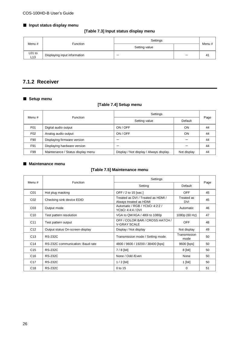
7.1.2 Receiver
■ Setup menu
[Table 7.4] Setup menu
Menu # Function Settings
Page Setting value Default
F01 Digital audio output ON / OFF ON 44
F02 Analog audio output ON / OFF ON 44
F90 Displaying firmware version - - 44
F91 Displaying hardware version - - 44
F99 Maintenance / Status display menu Display / Not display / Always display. Not display 44
■ Maintenance menu
[Table 7.5] Maintenance menu
Menu # Function Settings
Page Setting Default
C01 Hot plug masking OFF / 2 to 15 [sec.] OFF 45
C02 Checking sink device EDID Treated as DVI / Treated as HDMI /
Always treated as HDMI
Treated as
DVI 45
C03 Output mode Automatic / RGB / YCbCr 4:2:2 /
YCbCr 4:4:4 / DVI Automatic 46
C10 Test pattern resolution VGA to QWXGA / 480i to 1080p 1080p (60 Hz) 47
C11 Test pattern output OFF / COLOR BAR / CROSS HATCH /
V-GRAY SCALE OFF 48
C12 Output status On-screen-display Display / Not display Not display 49
C13 RS-232C Transmission mode / Setting mode. Transmission
mode 50
C14 RS-232C communication: Baud rate 4800 / 9600 / 19200 / 38400 [bps] 9600 [bps] 50
C15 RS-232C 7 / 8 [bit] 8 [bit] 50
C16 RS-232C None / Odd /Even None 50
C17 RS-232C 1 / 2 [bit] 1 [bit] 50
C18 RS-232C 0 to 15 0 51

COS-100HD-B User’s Guide
27
■ Output status display menu
[Table 7.6] Output status display menu
Menu # Function Settings
Page Setting value Default
[ L01 to
L07 ] Displaying output information - - 52
Tip: [ ] to the left of the each section title shows its menu name.

COS-100HD-B User’s Guide
28
7.2 Transmitter (Setup menu)
You can set transmitter’s input in normal use.
Tip: “[ ]” shows each menu number in this section.
7.2.1 [ F01 ] Copying EDID
EDID of sink devices can be read and stored in the transmitter. The copied EDID can be registered in the
transmitter to treat the EDID as same as the built-in EDID.
(1) Set [ F01 ] to “on” in order to read EDID of the sink device from the receiver’s HDMI output connector.
The read EDID will be copied to the transmitter.
(2) Set [ F02 ] to “02”. The copied EDID will be used.
Reading EDID
LC Monitor
Copied EDID
EXTERNAL(External EDID)
Built-in EDIDBlu-ray player
Step (1)Step (2)
RS
-23
2C
L AU
DIO
INP
UT
R
Tx
1 COAX Tx for HDMI COS-T100HD-B
FG
DC
5V
3A
HD
MI
OU
TP
UT
HD
MI
INP
UT
POWERSTATUS
LINK KEY LOCK
-+SET
SIGNAL HDCP
RS
-23
2C
FG
DC
5V
3A
HD
MI
Rx
COS-R100HD-B
LA
UD
IO O
UT
PU
TR
POWERSTATUS
LINK KEY LOCK
-+SET
SIGNAL HDCP
OU
TP
UT
INP
UT
1 COAX Rx for HDMI
OU
TP
UT
COS-R100HD-B (Receiver)
COS-T100HD-B (Transmitter)
Copying
[Fig. 7.1] Copying EDID
【See:7.2.2 [ F02 ] EDID resolution (P.29) 】
Setting values
on : Copying EDID
oFF : Not copying EDID [Default]
Note: For Daisy Chain connection, the transmitter copies the EDID from the sink device that is directly
connected to the receiver.
Blu-ray Player
LC Monitor
Cannot be copied
COS-T100HD-B (Transmitter)
COS-R100HD-B (Receiver)
Daisy Chain
connection
LC Monitor
Can be Copied
COS-R100HD-B (Receiver)
RS
-23
2C
L AU
DIO
INP
UT
R
Tx
1 COAX Tx for HDMI COS-T100HD-B
FG
DC
5V
3A
HD
MI
OU
TP
UT
HD
MI
INP
UT
POWERSTATUS
LINK KEY LOCK
-+SET
SIGNAL HDCP
RS
-23
2C
FG
DC
5V
3A
HD
MI
Rx
COS-R100HD-B
LA
UD
IO O
UT
PU
TR
POWERSTATUS
LINK KEY LOCK
-+SET
SIGNAL HDCP
OU
TP
UT
INP
UT
1 COAX Rx for HDMI
OU
TP
UT
RS
-23
2C
FG
DC
5V
3A
HD
MI
Rx
COS-R100HD-B
LA
UD
IO O
UT
PU
TR
POWERSTATUS
LINK KEY LOCK
-+SET
SIGNAL HDCP
OU
TP
UT
INP
UT
1 COAX Rx for HDMI
OU
TP
UT
[Fig. 7.2] EDID copy in Daisy Chain connection

COS-100HD-B User’s Guide
29
7.2.2 [ F02 ] EDID resolution
You can set the EDID that is sent to the source device.
03 to 22: Transmitter’s built-in EDID
If using built-in EDID, set the maximum resolution supported by the sink device.
Setting value
[Table 7.7] Maximum EDID resolution
Setting
value
Maximum resolution Pixel Standard Remarks
01 EXTERNAL (External
EDID)
- - When no EDID data, setting value “03”
will be applied.
02 Copied EDID
- - When no EDID data, setting value “03”
will be applied.
03 1080p (59.94/60) 1920×1080 HDTV Default
04 720p 1280×720
05 1080i 1920×1080
06 1080p (24/25/30/50) 1920×1080
07 SVGA 800×600 VESA
08 XGA 1024×768
09 VESA720 1280×720 CVT For DVI devices
10 WXGA 1280×768 VESA
11 WXGA 1280×800 MAC supported
12 Quad-VGA 1280×960
13 SXGA 1280×1024
14 WXGA 1360×768,
1366×768
Pixels can be set in “7.2.10 [ F10 ]
EDID WXGA (P.34)”
15 SXGA+ 1400×1050
16 WXGA+ 1440×900
17 WXGA++ 1600×900 Reduced Blanking
18 UXGA 1600×1200
19 WSXGA 1680×1050
20 VESA1080 1920×1080 CVT Reduced Blanking, For DVI devices
21 WUXGA 1920×1200 VESA Reduced Blanking
22 QWXGA 2048×1152 Reduced Blanking
【See:7.2.10 [ F10 ] EDID WXGA (P.34) 】

COS-100HD-B User’s Guide
30
[Table 7.8] Maximum resolution and EDID supported pixel
○: Supported, ×: Not supported
EDID supported
Max. resolution
640
x 480
800
x 600
1024
x 768
1280
x 720
1280
x 768
1280
x 800
1280
x 960
1280
x 1024
1360 x
768
※
1366 x
768
※
1400
x 1050
1440
x 900
1600
x 900
1600
x 1200
1680
x 1050
1920
x 1080
1920
x 1200
2048
x 1152
01 - - - - - - - - - - - - - - - - - - -
02 - - - - - - - - - - - - - - - - - - -
03 1080p (59.94/60) ○ ○ ○ × × ○ ○ ○ ○ ○ ○ ○ ○ ○ ○ ○ × ×
04 720p ○ ○ × ○ × × × × × × × × × × × × × ×
05 1080i ○ ○ ○ × × × × × × × × × × × × × × ×
06 1080p
(24/25/30p/50p) ○ ○ ○ × × ○ ○ ○ ○ ○ ○ ○ ○ ○ ○ ○ × ×
07 800x600 ○ ○ × × × × × × × × × × × × × × × ×
08 1024x768 ○ ○ ○ × × × × × × × × × × × × × × ×
09 1280x720 ○ ○ ○ ○ × × × × × × × × × × × × × ×
10 1280x768 ○ ○ ○ ○ ○ × × × × × × × × × × × × ×
11 1280x800 ○ ○ ○ ○ ○ ○ × × × × × × × × × × × ×
12 1280x960 ○ ○ ○ ○ ○ ○ ○ × × × × × × × × × × ×
13 1280x1024 ○ ○ ○ ○ ○ ○ ○ ○ × × × × × × × × × ×
14 1360x768 ○ ○ ○ ○ ○ ○ ○ ○ ○ ○ × × × × × × × ×
15 1400x1050 ○ ○ ○ ○ × ○ ○ ○ ○ ○ ○ × × × × × × ×
16 1440x900 ○ ○ ○ ○ × ○ ○ ○ ○ ○ ○ ○ × × × × × ×
17 1600x900 ○ ○ ○ ○ × ○ ○ ○ ○ ○ ○ ○ ○ × × × × ×
18 1600x1200 ○ ○ ○ ○ × ○ ○ ○ ○ ○ ○ ○ ○ ○ × × × ×
19 1680x1050 ○ ○ ○ ○ × ○ ○ ○ ○ ○ ○ ○ ○ ○ ○ × × ×
20 1920x1080 ○ ○ ○ × × ○ ○ ○ ○ ○ ○ ○ ○ ○ ○ ○ × ×
21 1920x1200 ○ ○ ○ × × ○ ○ ○ × × ○ ○ ○ ○ ○ ○ ○ ×
22 2048x1152 ○ ○ ○ × × × ○ ○ × × ○ ○ ○ ○ ○ ○ ○ ○
* The number of EDID-supported pixels for 1360×768 and 1366×768 can be set in “EDID WXGA”. The
default value is 1360×768.
【See:7.2.10 [ F10 ] EDID WXGA (P.34) 】
COS-100HD-B User’s Guide
31
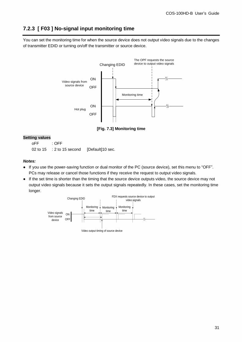
7.2.3 [ F03 ] No-signal input monitoring time
You can set the monitoring time for when the source device does not output video signals due to the changes
of transmitter EDID or turning on/off the transmitter or source device.
Changing EDID
ON
OFF
The OPF requests the source
device to output video signals
Monitoring time
Hot plugON
OFF
Video signals from
source device
[Fig. 7.3] Monitoring time
Setting values
oFF : OFF
02 to 15 : 2 to 15 second [Default]10 sec.
Notes:
● If you use the power-saving function or dual monitor of the PC (source device), set this menu to “OFF”.
PCs may release or cancel those functions if they receive the request to output video signals.
● If the set time is shorter than the timing that the source device outputs video, the source device may not
output video signals because it sets the output signals repeatedly. In these cases, set the monitoring time
longer.
Changing EDID
Monitoring
time
ON
OFF
Monitoring
time
Monitoring
time
Video output timing of source device
Video signals
from source
device
FDX requests source device to output
video signals
COS-100HD-B User’s Guide
32
7.2.4 [ F04 ] PCM Audio
You can set the maximum sampling frequency of PCM Audio output from the source device.
Setting values
32 : 32 kHz
44 : 44.1 kHz
48 : 48 kHz [Default]
88 : 88.2 kHz
96 : 96 kHz
192 : 192 kHz
Note: For audio sampling frequency that is output from a receiver is 48 kHz.
7.2.5 [ F05 ] AC-3 Dolby Digital Audio
You can enable and disable AC-3 Dolby Digital Audio input.
Setting values
on : 48 kHz
oFF : OFF [Default]
Note: For compressed audio input, only 48 kHz is available.
7.2.6 [ F06 ] AAC Audio
You can enable and disable AAC Audio input.
Setting values
on : 48 kHz
oFF : OFF [Default]
Note: For compressed audio input, only 48 kHz is available.
7.2.7 [ F07 ] Dolby Digital Plus Audio
You can enable and disable Dolby Digital Plus Audio input.
Setting values
on : 48 kHz
oFF : OFF [Default]
Note: For compressed audio input, only 48 kHz is available.

COS-100HD-B User’s Guide
33
7.2.8 [ F08 ] DTS Audio
You can enable and disable DTS Audio
Setting values
on : 48 kHz
oFF : OFF [Default]
Note: For compressed audio input, only 48 kHz is available.
7.2.9 [ F09 ] Audio channel
You can set the number of channels to the audio of multi-channel output that is output from the source device.
Setting values
02 : 2 channels [Default]
03 : 3 channels (2.1 channels)
06 : 6 channels (5.1 channels)
08 : 8 channels (7.1 channels)
■ The number of channels and speaker configuration
RL
RLC RRC
RR
FR
FC
FL
LFE
FL : Front Left
FC : Front Center
FR : Front Right
RL : Rear Left
RR : Rear Right
RLC : Rear Left Center
RRC : Rear Right Center
LFE : Low Frequency Effect
The number of
channels FL/FR LFE FC RL/RR RLC/RRC
02 (2 channels) ON OFF OFF OFF OFF
03 (2.1 channels) ON ON OFF OFF OFF
06 (5.1 channels) ON ON ON ON OFF
08 (7.1 channels) ON ON ON ON ON
[Fig. 7.4] The number of channels and speaker configuration

COS-100HD-B User’s Guide
34
7.2.10 [ F10 ] EDID WXGA
You can set the number of pixels of WXGA (1360×768 / 1366×768) depending on the EDID resolution.
【See:7.2.2 [ F02 ] EDID resolution (P.29) 】
Setting values
on : 1366×768
oFF : 1360×768 [Default]
7.2.11 [ F11 ] Analog / Digital audio
You can select input audio.
Setting values
oFF : OFF
d : Digital audio [Default]
A : Analog audio
Note: If DVI signal is input and analog audio is selected, embedded HDMI signal is output.
7.2.12 [ F90 ] Displaying firmware version
You can display the firmware version.
7.2.13 [ F91 ] Displaying hardware version
You can display the hardware version.
7.2.14 [ F99 ] Maintenance / Status display menu
You can set how the maintenance menu and status display menu are displayed.
Setting value
oFF : Not displayed [Default]
on : Displayed (not displayed when the COS is turned on next time)
ALL : Always displayed (displayed when the COS is turned on next time as well)

COS-100HD-B User’s Guide
35
7.3 Transmitter (Maintenance menu)
You can set the required items for operation verification.
Set [F99] to “ALL” or “on” in order to enable the maintenance menu.
【See:7.2.14 [ F99 ] (P.34) 】
7.3.1 [ C01 ] HDCP input setting
You can set whether the transmitter encrypts HDCP to the source device.
Some source devices check whether the connected device supports HDCP and then determine whether they
encrypt HDCP signals or not. Since the transmitter is HDCP compliant, if it is connected to a sink device that
is not HDCP compliant, the sink device may not display video. In this case, set this menu to “oFF” in order to
display the video.
HDCP-
compliant PC
Without
copyright
protection
With copyright
protection HDCP input setting:
“on”
Video cannot be
displayed
Video can be
displayed
Video can be
displayed
HDCP-non-compliant sink
device
HDCP-compliant/non-compliant sink device
HDCP-compliant sink device
COS-T100HD-B (Transmitter) COS-R100HD-B (Receiver)
HDCP input setting:
“oFF”
RS
-23
2C
L AU
DIO
INP
UT
R
Tx
1 COAX Tx for HDMI COS-T100HD-B
FG
DC
5V
3A
HD
MI
OU
TP
UT
HD
MI
INP
UT
POWERSTATUS
LINK KEY LOCK
-+SET
SIGNAL HDCP
RS
-23
2C
L AU
DIO
INP
UT
R
Tx
1 COAX Tx for HDMI COS-T100HD-B
FG
DC
5V
3A
HD
MI
OU
TP
UT
HD
MI
INP
UT
POWERSTATUS
LINK KEY LOCK
-+SET
SIGNAL HDCP
RS
-23
2C
FG
DC
5V
3A
HD
MI
Rx
COS-R100HD-B
LA
UD
IO O
UT
PU
TR
POWERSTATUS
LINK KEY LOCK
-+SET
SIGNAL HDCP
OU
TP
UT
INP
UT
1 COAX Rx for HDMI
OU
TP
UT
RS
-23
2C
FG
DC
5V
3A
HD
MI
Rx
COS-R100HD-B
LA
UD
IO O
UT
PU
TR
POWERSTATUS
LINK KEY LOCK
-+SET
SIGNAL HDCP
OU
TP
UT
INP
UT
1 COAX Rx for HDMI
OU
TP
UT
COS-T100HD-B (Transmitter) COS-R100HD-B (Receiver)
[Fig. 7.5] HDCP and sink devices
Setting value
on : HDCP enabled [Default]1
oFF : HDCP disabled
Note: Set this menu to “on” in order to display copyright protected contents.

COS-100HD-B User’s Guide
36
7.3.2 [ C10 ] Test pattern resolution
You can set the output resolution of the built-in test pattern of the transmitter.
If setting [ C11 ] to a value other than “oFF”, the test pattern will be output at the resolution that is set in this
menu.
Setting values
[Table 7.9] Test pattern resolution
【See:7.3.3 [ C11 ] Test pattern output (P.37)】
Setting
values
Resolution Pixels Frequency Remarks
01 VGA 640×480 60 Hz
02 SVGA 800×600 60 Hz
03 XGA 1024×768 60 Hz
04 WXGA 1280×768 60 Hz
05 WXGA 1280×800 60 Hz
06 Quad-VGA 1280×960 60 Hz
07 SXGA 1280×1024 60 Hz
08 SXGA+ 1400×1050 60 Hz
09 WXGA+ 1440×900 60 Hz
10 WXGA++ 1600×900 60 Hz
11 UXGA 1600×1200 60 Hz
12 WSXGA+ 1680×1050 60 Hz
13 VESA HD 1920×1080 60 Hz
14 WUXGA 1920×1200 60 Hz Reduced Blanking
15 QWXGA 2048×1152 60 Hz Reduced Blanking
16 480i 720×480 59.94 Hz
17 480p 720×480 59.94 Hz
18 576i 720×576 50 Hz
19 576p 720×576 50 Hz
20 720p 1280×720 50 Hz
21 720p 1280×720 59.94 Hz
22 720p 1280×720 60 Hz
23 1080i 1920×1080 50 Hz
24 1080i 1920×1080 59.94 Hz
25 1080i 1920×1080 60 Hz
26 1080p 1920×1080 50 Hz
27 1080p 1920×1080 59.94 Hz
28 1080p 1920×1080 60 Hz Default

COS-100HD-B User’s Guide
37
7.3.3 [ C11 ] Test pattern output
You can switch built-in test patterns, and the selected test pattern will be output at the resolution that is set in
[ C10 ]. Video signal input is not necessary when a test pattern is output.
For 01, 03, and 05, the built-in test tone is also output. Audio signal input is not necessary when the test tone
is output.
The number of test tone channels: 8
Output frequency: 1 kHz (LFE: 80 Hz)
Sampling frequency: 48 kHz
【See:7.3.2 [ C10 ] (P.36) 】
Setting values
oFF : OFF [Default]
01 : COLOR BAR (With test tone)
02 : COLOR BAR (Without test tone)
03 : CROSS HATCH (With test tone)
04 : CROSS HATCH (Without test tone)
05 : V-GRAY SCALE (With test tone)
06 : V-GRAY SCALE (Without test tone)
Notes: If you set test pattern output for both transmitter and receiver, receiver’s test pattern will be output.
OFF(Normal video output)
COLOR BAR CROSS HATCH V-GRAY SCALE

COS-100HD-B User’s Guide
38
7.3.4 [ C12 ] Input status On-screen-display
You can display the signal status that is input to the transmitter on the screen.
Setting values
on : OSD enabled
oFF : OSD disabled [Default]
<InputStatus> [COS-T100HD-B] [VideoStatus] Format :1920x1080p 59.94Hz InputMode:HDMIMode HDCP ON Color :8Bit YCbCr4:4:4
[AudioStatus] Format :L-PCM 48kHz Channel :2ch
[TestPattern(TX)] Format :1080p 60Hz
[Version(TX)] Soft/Hard:1.00/1.00
②
⑤
④
①
③
[Fig. 7.6] Input status OSD
[Table 7.10] Description of input status
# Description
① Model name
② Input video signal
Format : Input resolution, input vertical synchronous frequency
InputMode : Input mode (HDMI / DVI), with or without HDCP
Color : Color depth, color space
③ Digital audio input signal
Format : Input audio format, input sampling frequency
Channel : The number of input audio channels
④ Data of output test pattern information
Format : Resolution of output test pattern, Vertical synchronous frequency
(When no test pattern is output: “OFF”)
⑤ Version
Soft / Hard: Software version / Hardware version
Notes:
If the on-screen display function is set for both transmitter and receiver, the input status of the transmitter
is not displayed.
If the on-screen display function of transmitter and the test pattern output function of receiver are set to
enabled, the former is not displayed.

COS-100HD-B User’s Guide
39
7.3.5 [ C13 ] RS-232C communication mode
You can set the RS-232C communication mode to control the transmitter and communicate with the receiver.
Setting values
00 : Transmission mode [Default]
01 : Setting mode
7.3.6 [ C14 ] RS-232C communication: Baud rate
You can set the baud rate for RS-232C communication between the transmitter and control device.
This setting will be applied for both modes (“00” and “01”) set in [ C13 ].
【See:7.3.5 [ C13 ] RS-232C communication mode (P.39) 】
Setting values
48 : 4800 [bps]
96 : 9600 [bps] [Default]
192 : 19200 [bps]
384 : 38400 [bps]
7.3.7 [ C15 ] RS-232C communication: Data bit length
You can set the data bit length for RS-232C communication between the transmitter and control device.
This setting will be applied for both modes (“00” and “01”) set in [ C13 ].
【See:7.3.5 [ C13 ] RS-232C communication mode (P.39) 】
Setting values
07 : 7 [bit]
08 : 8 [bit] [Default]
7.3.8 [ C16 ] RS-232C communication: Parity check
You can set the parity check for RS-232C communication between the transmitter and control device.
This setting will be applied for both modes (“00” and “01”) set in [ C13 ].
【See:7.3.5 [ C13 ] RS-232C communication mode (P.39) 】
Setting values
Non : None [Default]
odd : Odd
En : Even

COS-100HD-B User’s Guide
40
7.3.9 [ C17 ] RS-232C communication: Stop bit
You can set the stop bit for RS-232C communication between the transmitter and control device.
This setting will be applied for both modes (“00” and “01”) set in [ C13 ].
【See:7.3.5 [ C13 ] RS-232C communication mode (P.39) 】
Setting values
01 : 1 [bit] [Default]
02 : 2 [bit]

COS-100HD-B User’s Guide
41
7.4 Transmitter (Displaying input status)
You can set status display menus in this section if [ F99 ] is set to “on” or “ALL”.
Press the “SET” button to apply the setting.
【See:7.2.14 [ F99 ] (P.34)】
7.4.1 [ L01 to L13 ] Displaying input information
[Table 7.11] Input information of transmitter
Menu # Value Description
● HDMI / DVI mode and color depth
Note: Even if 30 bit / pixel or larger signal is input, the output is 24 bit / pixel.
L01 H08 HDMI mode 24 bit / pixel (8bit / component)
H10 HDMI mode 30 bit / pixel (10bit / component)
H12 HDMI mode 36 bit / pixel (12bit / component)
d08 DVI mode 24 bit / pixel (8bit / component)
- - - No input
● With / Without HDCP
L02 on With HDCP
oFF Without HDCP
- - - No input
● Color space
L03 rgb RGB
422 YCbCr 4:2:2
444 YCbCr 4:4:4
- - - Unknown or no input
● Video frequency
L04 59.9 Input vertical synchronous frequency (for 59.9 Hz)
- - - No input
● DDC power
L05 on DDC power is input
oFF No DDC power is input
● Resolution
L06 192 Input resolution (scrolling display)
- - - No input

COS-100HD-B User’s Guide
42
[Table 7.12] Input information of transmitter (cont’d)
Menu # Value Description
● Audio input format (2 digits from left) and the number of channels (1 digit from
right)
X= the number of channels: 2 = 2 channels, 3 = 2.1 channels, 6 = 5.1channels,
8 = 7.1 channels
L10 - - - Unknown or no input
00X Unknown
01X PCM Audio
02X AC-3 Audio
03X MPEG-1 Audio
04X MP3 Audio
05X MPEG-2 Audio
06X AACLC Audio
07X DTS Audio
08X ATRAC Audio
09X DSD Audio
10X Dolby Digital Plus Audio
11X DTS-HD Audio
12X Dolby TrueHD Audio
13X DST Audio
14X WMA Audio
15X HE-AAC / HE-AACv2 / MPEG Surround Audio
● Sampling frequency of digital audio input
Note: For compressed audio input, only 48 kHz is available.
L11 22 22.05 kHz
24 24 kHz
32 32 kHz
44 44.1 kHz
48 48 kHz
88 88.2 kHz
96 96 kHz
176 176.4 kHz
192 192 kHz
768 768 kHz
_01 Unknown
_05
_07
_11
_13
_15
- - - No input

COS-100HD-B User’s Guide
43
[Table 7.13] Input information of transmitter (cont’d)
Menu # Value Description
● The number of digital audio input bit, HBR mode (High Bit-Rate Audio)
Note: HBR is not supported.
L12 H16 16 bit, HBR mode
P16 16 bit, PCM mode
: :
H24 24 bit, HBR mode
P24 24 bit, PCM mode
- - - No input
● Digital audio input status
L13 00 No audio input
01 Input is being detected.
02
03
04
05
06
07 Normal input.
- - - No input

COS-100HD-B User’s Guide
44
7.5 Receiver (Setting menu)
You can set receiver’s input in normal use.
Tip: “[ ]” shows each menu number in this section.
7.5.1 [ F01 ] Digital audio output
You can enable and disable digital audio output.
Setting values
on : ON [Default]
oFF : OFF
7.5.2 [ F02 ] Analog audio output
You can enable and disable analog audio output.
Setting values
on : ON [Default]
oFF : OFF
Note: If compressed audio (Dolby Digital, DTS and the like) is input, analog audio is not output.
7.5.3 [ F90 ] Displaying firmware version
You can display the firmware version.
7.5.4 [ F91 ] Displaying hardware version
You can display the hardware version.
7.5.5 [ F99 ] Maintenance / Status display menu
You can set how the maintenance menu and status display menu are displayed.
Setting value
oFF : Not displayed [Default]
on : Displayed (not displayed when the COS is turned on next time)
ALL : Always displayed (displayed when the COS is turned on next time as well)

COS-100HD-B User’s Guide
45
7.6 Receiver (Maintenance menu)
You can set the required items for operation verification.
Set [F99] to “ALL” or “on” in order to enable the maintenance menu.
【See:7.5.5 [ F99 ] (P.44) 】
7.6.1 [ C01 ] Hot plug masking
You can set the time for ignoring video output request signal that is sent from the sink device.
If the sink device repeatedly sends video output request in a short cycle, the receiver sets video output every
time. In such a case, video may not be output.
This problem can be solved by setting the time for ignoring video output request signal.
【See:7.2.3 [ F03 ] (P.31) 】
Setting values
oFF : Without masking processing [Default]
02 to 15 : 2 to 15 [sec.]
7.6.2 [ C02 ] Checking sink device EDID
You can set the sink device’s EDID checking method.
The receiver acquires EDID from the sink device and determines whether the sink device is HDMI or DVI
device. However, if the receiver cannot acquire the EDID for any reason, audio may not be output. In such a
case, the COS determines the sink device is an HDMI device.
Setting values
oFF : DVI device in case of EDID reading error [Default]
Err : HDMI device in case of EDID reading error
ALL : HDMI device at all times
Notes:
If selecting “Err” or “ALL”, set the transmitter’s EDID resolution to a resolution other than “EXTERNAL” and set
the appropriate EDID.
If the source device cannot acquire the EDID, video and audio may not be output correctly.
This setting is valid only if the output mode is set to a value other than “d”.
【See:7.2.2 [ F02 ] EDID resolution (P.29) 】
【See:7.6.3 [ C03 ] Output mode (P.46) 】

COS-100HD-B User’s Guide
46
7.6.3 [ C03 ] Output mode
You can set the color space that will be sent to the sink device.
The sink device automatically selects the optimal color space. However, if the sink device does not select the
color space for any reason, use this menu.
Setting values
oFF : Automatic [Default]
rgb : RGB
422 : YCbCr 4:2:2
444 : YCbCr 4:4:4
d : DVI
Note: This setting is valid only if HDMI signal is input.

COS-100HD-B User’s Guide
47
7.6.4 [ C10 ] Test pattern resolution
You can set the output resolution of the built-in test pattern of the receiver.
If setting [ C11 ] to a value other than “oFF”, the test pattern will be output at the resolution that is set in this
menu.
Setting values
[Table 7.14] Test pattern resolution
【See:7.6.5 [ C11 ] (P.48) 】
Setting
values
Resolution Pixels Frequency Remarks
01 VGA 640×480 60 Hz
02 SVGA 800×600 60 Hz
03 XGA 1024×768 60 Hz
04 WXGA 1280×768 60 Hz
05 WXGA 1280×800 60 Hz
06 Quad-VGA 1280×960 60 Hz
07 SXGA 1280×1024 60 Hz
08 SXGA+ 1400×1050 60 Hz
09 WXGA+ 1440×900 60 Hz
10 WXGA++ 1600×900 60 Hz
11 UXGA 1600×1200 60 Hz
12 WSXGA+ 1680×1050 60 Hz
13 VESA HD 1920×1080 60 Hz
14 WUXGA 1920×1200 60 Hz Reduced Blanking
15 QWXGA 2048×1152 60 Hz Reduced Blanking
16 480i 720×480 59.94 Hz
17 480p 720×480 59.94 Hz
18 576i 720×576 50 Hz
19 576p 720×576 50 Hz
20 720p 1280×720 50 Hz
21 720p 1280×720 59.94 Hz
22 720p 1280×720 60 Hz
23 1080i 1920×1080 50 Hz
24 1080i 1920×1080 59.94 Hz
25 1080i 1920×1080 60 Hz
26 1080p 1920×1080 50 Hz
27 1080p 1920×1080 59.94 Hz
28 1080p 1920×1080 60 Hz Default

COS-100HD-B User’s Guide
48
7.6.5 [ C11 ] Test pattern output
You can switch built-in test patterns, and the selected test pattern will be output at the resolution that is set in
[ C10 ]. Video signal input is not necessary when a test pattern is output.
For 01, 03, and 05, the built-in test tone is also output. Audio signal input is not necessary when the test tone
is output.
The number of test tone channels: 8
Output frequency: 1 kHz (LFE: 80 Hz)
Sampling frequency: 48 kHz
【See:7.6.4 [ C10 ] (P.47) 】
Setting values
oFF : OFF [Default]
01 : COLOR BAR (With test tone)
02 : COLOR BAR (Without test tone)
03 : CROSS HATCH (With test tone)
04 : CROSS HATCH (Without test tone)
05 : V-GRAY SCALE (With test tone)
06 : V-GRAY SCALE (Without test tone)
Notes: If you set test pattern output for both transmitter and receiver, receiver’s test pattern will be output.
OFF(Normal video output)
COLOR BAR CROSS HATCH V-GRAY SCALE

COS-100HD-B User’s Guide
49
7.6.6 [ C12 ] Output status On-screen-display
You can display the signal status that is output to the receiver on the screen.
Setting values
on : OSD enabled
oFF : OSD disabled [Default]
<OutputStatus> [COS-R100HD-B] [MonitorStatus] Color :8bit YCbCr4:4:4 Mode :HDMIMode Audio :L-PCM 48kHz 2ch HDCP :Support
[OutStatus] Color :RGB HDCP :Auth OK
[TestPattern(RX)] Format :OFF
[Version(RX)] Soft/Hard:1.00/1.00
②
⑤
④
①
③
[Fig. 7.7] Output status OSD
[Table 7.15] Description of input status
# Description
① Model name
② Sink device status
Color : Color depth, color space
Mode : mode (HDMI / DVI)
Audio : Audio format, sampling frequency, the number of audio channels
HDCP : Supported / Not supported
③ Output signal status
Color : Color space
HDCP : HDCP Authentication Status
④ Data of output test pattern information
Format : Resolution of output test pattern, Vertical synchronous frequency
(When no test pattern is output: “OFF”)
⑤ Version
Soft / Hard: Software version / Hardware version
Note: If the on-screen display function is set for both transmitter and receiver, the input status of the
transmitter is not displayed.

COS-100HD-B User’s Guide
50
7.6.7 [ C13 ] RS-232C communication mode
You can set the RS-232C communication mode to control the receiver and communicate with the transmitter.
Setting values
00 : Transmission mode [Default]
01 : Setting mode
7.6.8 [ C14 ] RS-232C communication: Baud rate
You can set the data bit length for RS-232C communication between the receiver and control device.
This setting will be applied for both modes (“00” and “01”) set in [ C13 ].
【See:7.6.7 [ C13 ] RS-232C (P.50) 】
Setting values
48 : 4800 [bps]
96 : 9600 [bps] [Default]
192 : 19200 [bps]
384 : 38400 [bps]
7.6.9 [ C15 ] RS-232C communication: Data bit length
You can set the data bit length for RS-232C communication between the receiver and control device.
This setting will be applied for both modes (“00” and “01”) set in [ C13 ].
【See:7.6.7 [ C13 ] RS-232C (P.50) 】
Setting values
07:7 [bit]
08:8 [bit] [Default]
7.6.10 [ C16 ] RS-232C communication: Parity check
You can set the parity check for RS-232C communication between the receiver and control device.
This setting will be applied for both modes (“00” and “01”) set in [ C13 ].
【See:7.6.7 [ C13 ] RS-232C (P.50) 】
Setting values
non : None [Default]
odd : Odd
En : Even
7.6.11 [ C17 ] RS-232C communication: Stop bit
You can set the stop bit for RS-232C communication between the transmitter and control device.
This setting will be applied for both modes (“00” and “01”) set in [ C13 ].
【See:7.6.7 [ C13 ] RS-232C (P.50) 】
Setting values

COS-100HD-B User’s Guide
51
01 : 1 [bit] [Default]
02 : 2 [bit]
7.6.12 [ C18 ] RS-232C communication: Receiver ID
You can set the ID for serial transmission with a specified receiver in Daisy Chain connection.
Set the receiver ID to “00” to transmit the data to a specified receiver.
This setting is valid only if [ C13 ] is set to “00” (Transmission mode).
【See:7.6.7 [ C13 ] RS-232C (P.50) 】
Setting values
00 : ID for unspecified receiver [Default]
01 to 15 : ID for specified receiver

COS-100HD-B User’s Guide
52
7.7 Receiver (Displaying output status)
You can set status display menus in this section if [ F99 ] is set to “on” or “ALL”.
Press the “SET” button to apply the setting.
【See:7.5.5 [ F99 ] (P.44) 】
7.7.1 [ L01 to L07 ] Displaying output information
[Table 7.16] Output information of receiver
Menu # Value Description
● Color depth
Note: 24 bit / pixel fixed from receiver
L01 08 24 bit / pixel (8bit / component)
10 30 bit / pixel (10bit / component)
12 36 bit / pixel (12bit / component)
- - - Not connected
● Color space supported (sink device)
L02 rgb RGB supported
422 YCbCr 4:2:2 supported
444 YCbCr 4:4:4 supported
- - - Not connected
● Color space: Output status
L03 rgb RGB output
422 YCbCr 4:2:2 output
444 YCbCr 4:4:4 output
- - - Not connected
● Hot plug detection
L04 on Hot plug detected
oFF No hot plug detected
● HDMI / DVI
L05 HC HDMI mode (Compressed audio)
HP HDMI mode (PCM audio)
d DVI mode (Audio is not supported)
- - - Not connected
● HDCP authentication
L06 00 None
01 Being authenticated
02
03
04 Ended normally
05 Ended abnormally

COS-100HD-B User’s Guide
53
[Table 7.17] Output information of receiver (cont’d)
Menu # Value Description
● HDCP
L07 on HDCP supported
oFF HDCP not supported
- - - Not connected

COS-100HD-B User’s Guide
54
8 Product specification
8.1 Pin assignment
8.1.1 HDMI TypeA connector
Pin # Signal name Pin # Signal name
1 TMDS data 2+ 10 TMDS clock+
2 TMDS data 2 shield 11 TMDS clock shield
3 TMDS data 2- 12 TMDS clock
4 TMDS data 1+ 13 CEC
5 TMDS data 1 shield 14 spare (N.C.*)
6 TMDS data 1- 15 SCL
7 TMDS data 0+ 16 SDA
8 TMDS data 0 shield 17 DDC / CEC ground
9 TMDS data 0- 18 +5 power supply
19 Detecting hot plug
*N.C.: No Connection
[Fig. 8.1] HDMI TypeA pin assignment
8.1.2 RS-232C connector
D-sub 9 pin, male
RS-232C connector
1 5
6 9
[Fig. 8.2] RS-232C connector pin assignment
1
2
19
18

COS-100HD-B User’s Guide
55
■ Connection to PCs
Make sure to use a cross cable in order to connect to a PC.
RD
TD
N.C.
N.C.
N.C.
N.C.
GND
RTS
CTS
Pin No.
1
3
2
4
6
5
7
9
8
Signal
RD
TD
N.C.
N.C.
N.C.
N.C.
GND
RTS
CTS
Signal
(RX data)
(TX data)
(Ground)
(TX request)
(RX request)
OPF-H1000D PC
(No connection)
(No connection)
(No connection)
(No connection)
[Fig. 8.3] COS-100HD-B and PC are connected
■ Connecting to an IDK’s product
Make sure to use a cross cable in order to connect to an IDK’s product.
RD
TD
N.C.
N.C.
N.C.
N.C.
GND
RTS
CTS
Pin No.
1
3
2
4
6
5
7
9
8
Signal
RD
TD
N.C.
N.C.
N.C.
N.C.
GND
RTS
CTS
Signal
(RX data)
(TX data)
(Ground)
(TX request)
(RX request)
OPF-H1000D IDK’s product
(No connection)
(No connection)
(No connection)
(No connection)
[Fig. 8.4] COS-100HD-B and IDK’s product are connected
■ Connecting to a product requiring straight cabling
Make sure to use a straight cable in order to connect to a product that needs straight cabling.
RD
TD
N.C.
N.C.
N.C.
N.C.
GND
RTS
CTS
Pin No.
1
3
2
4
6
5
7
9
8
Signal
TD
RD
N.C.
N.C.
N.C.
N.C.
GND
CTS
RTS
Signal
(RX data)
(TX data)
(Ground)
(TX request)
(RX request)
OPF-H1000D Another company’s product
(No connection)
(No connection)
(No connection)
(No connection)
[Fig. 8.5] COS-100HD-B and another company’s product requiring straight cabling are connected

COS-100HD-B User’s Guide
56
8.2 Product specification
Item Description
Model number COS-T100HD (Transmitter) COS-R100HD (Receiver)
Input
Video
HDMI/
DVI
Number/
Signal
1 input/HDMI (HDCP 1.4) (*1)
TMDS Single Link
TMDS clock
- 25 MHz to 165 MHz
Built-in EDID emulation
1 input/Digital signals for extension
Connector 1 female HDMI Type A (*2) 1 BNC 75Ω
Others Color depth: 24 bit (*3)
Formats
480i / 480p / 576i / 576p / 720p / 1080i / 1080p
VGA to QWXGA
* WUXGA / QWXGA only support Reduced Blanking
Audio
Digital
Number/
Signal
1 input/Multi-channel linear PCM
up to 8 channels
- Sampling frequency: 32kHz to 192kHz
- Sample Size: 16bit to 24bit
- Reference level:-20 dBFS
- Max. input level: 0 dBFS
1 input/Digital signals for extension
Connector 1 female HDMI Type A (*2) 1 BNC 75Ω
Analog
Number/
Signal
1 input / stereo LR unbalanced signals
- Input impedance: 24 kΩ
- Reference level: -10 dBu
- Max input level: +10 dBu
-
Connector 1 RCA pin jack -
Output
Video
HDMI/
DVI
Number/
Signal 1 output / Digital signals for extension
1 output/HDMI (HDCP 1.4) (*1)
TMDS Single Link
TMDS clock
- 25 MHz to 165 MHz
Connector 1 BNC 75Ω 1 female HDMI Type A (*2)
Daisy
Chain
Number/
Signal - 1 input/Digital signals for extension
Connector - 1 BNC 75Ω
Others Color depth: 24 bit (*3)
Formats
480i / 480p / 576i / 576p / 720p / 1080i / 1080p
VGA to QWXGA
* WUXGA / QWXGA only support Reduced Blanking
Audio
Digital
Number/
Signal 1 output/Digital signals for extension
1 output/Multi-channel linear PCM
up to 8 channels
- Sampling frequency: 48kHz
- Sample Size: 24bit
- Reference level:-20 dBFS
- Max. input level: 0 dBFS
Connector 1 BNC 75Ω 1 female HDMI Type A
Analog Number/
Signal -
1 output/stereo LR unbalanced signals
(*4)

COS-100HD-B User’s Guide
57
- Input impedance: 75 kΩ
- Reference level: -10 dBu
- Max input level: +10 dBu
Connector - 1 RCA pin jack
Plug & Play DDC2B (Built-in EDID: It can select maximum resolution)
Coaxial cables 75 Ω coaxial cable for high frequency signal
Signal transmission distance
L-7CHD: Up to 688.97 ft. / 210 m
L-7CFB: Up to 492.13 ft. / 150 m L-5CFB: Up to 360.89 ft. / 110 m L-5C2V: Up to 196.85 ft. / 60 m
L-3CFB: Up to 262.47 ft. / 80 m L-3C2V: Up to 131.23 ft. / 40 m *Please be careful to use it with an adequate cable length
*This distance may shorten due to jitter performance of the input video signals
*Number of daisy chaining may be limited or cable extension distance may shorten if
jitter performance at daisy chaining had degraded
Functions Anti-Snow (*5), Connection Reset (*6)
Control Serial control port
Number/
Signal 1 port / Full duplex Max. 115.2kbps
Connector 1 male 9-pin D-Sub
Others
AC adapter Input: 100 - 240 VAC ± 10 %, 50 Hz / 60 Hz ± 3 Hz
Output: 5VDC 3A 15Watt (AC adapter is supplied)
Power consumption About 6 Watts About 6 Watts
Dimensions 4.17 × 1.10 × 5.91" / 106 (W) × 28 (H) × 150 (D) mm
(Quarter rack wide) (Excluding connectors and the like)
Weight 1.1 lbs. (0.5 kg)
Temperature Operating: 32°F to 104°F / 0°C to +40°C
Storage: -4°F to +176°F / -20°C to +80°C
Humidity Operating/ Storage: 20 % to 90 % (Non Condensing)
(*1) This product does not support CEC, xvYCC, , 3D, ARC, HEC
(*2) Please use an HDMI cable shorter than 5 m
(*3) Deep Color is not supported.
(*4) Analog audio output only supports 2 channels liner PCM
(*5) Anti-snow function can fix snowy noise automatically that is a specific symptom of the signal having HDCP, mainly snow noise that
arises during starting. Therefore, this function cannot work when snow noise has already occurred before starting or when snowy
noise occurs because of bad status of transmission line.
(*6) Connection reset function can fix problems that can be repaired by taking off and putting in connectors. This function can work only
in this product's output port, which sometimes will not take effect if another device is between output of this product and d isplay
device

COS-100HD-B User’s Guide
58
9 Troubleshooting
In case the COS-100HD-B does not work correctly, please check the following items first. Also refer to
manuals for connected devices as well, since they may possibly be the cause of the problem.
・Is the COS-100HD-B powered on correctly?
・Are cables connected correctly?
・Are there no short circuits, disconnections, or loose connections?
・Are appropriate cables for the COS-100HD-B being used?
・Connected devices are set correctly?
・Are there any nearby objects that may cause noise?
If additional assistance is required, please check the following items and refer to manuals of connected
devices as well.
Problem Cause/Check item/Solution Page #
● Video output
Video is not output. If there are no problems with cable connections, first check [1] and
[2] below.
-
[1]
Is the EDID resolution setting of this device set to the input
resolution supported by the display device?
・If the EDID resolution is set to 1080i, some TVs do not
support that resolution.
・For output resolution for TVs (480i to 1080p), check the
vertical synchronous frequency .
・For output resolution for PCs (VGA to QWXGA), video may
not be output to LC monitors.
29
[2] Are signals output from the input device?
If the SIGNAL LED of the transmitter illuminates, check
[3]to[7];if it does not illuminate, check [8] and [9].
12
[3] If signals protected by HDCP are input, does the sink device
support the HDCP?
If the sink device that is not HDCP compliant is connected:
- only video without content protection (such as analog input
and test pattern) can be output
- black is output when signal with content protection is input.
Some source devices check whether the sink device is HDCP
compliant or not and they output video depending on the
result. In such a case, disable HDCP input in “7.3.1 [ C01 ]
HDCP input setting”.
35
[4] If a test pattern of the transmitter is displayed, the input side
has problems. replace the HDMI cable with a shorter one (16
ft. (5 m) or shorter).
If a test pattern of the receiver is not displayed, the output side
has problems.
-

COS-100HD-B User’s Guide
59
Problem Cause/Check item/Solution Page #
● Video output (Cont’d)
Video is not output
from input.
[5] If the transmitter’s test pattern is not displayed while receiver’s
test pattern is displayed, the coaxial cable has problems.
Replace the cable with a shorter cable.
16
[6] The COS-100HD-B supports only 25 MHz to 165 MHz dot
clock.
-
[7] Change the setting of Hot plug masking. 45
[8] Is the “No-signal input” monitoring time too short? 31
[9] Check the video output setting of the source device. -
Interference or noise
appears on video.
If a test pattern of the transmitter is displayed, the input side has
problems. replace the HDMI cable with a shorter one (16 ft. (5 m) or
shorter).
If a test pattern of the receiver is not displayed, the output side has
problems.
16
If the problem occurs in the transmitter side while it does not in the
receiver side, the coaxial cable has problems.
If a long cable is connected for input or output, replace it with a
shorter cable. The problem may occur due to the cable’s quality or
the connected device. If the problem is solved by the replacement,
the signals may be deteriorated because of the long-distance
transmission.
16
If a coaxial cable length exceeds its maximum transmission
distance, the video may be interrupted or noise appears. Even
within the maximum transmission distance, if the cable is
connected using a cable joint (JJ), the signals may not be
transmitted to the distance mentioned in the specification. The
similar problems may occur if the number of Daisy chain devices
exceeds the maximum number (15 devices). The maximum
transmission distance and the maximum number of Daisy chain
devices of this device depends on each input resolution.
16
When high-speed signals (e.g.: high-resolution signals such as
UXGA, WUXGA, and 1080p) are input or output, video may not be
displayed or noise may appear depending on the cable quality and
connected devices.
Set the EDID in order to control the resolution and color depth of
input signals.
29
Video blinks. If interlace signals are input to a display device that does not
support interlaced signals, the video blinks. Check the supported
resolution of the monitor.
-

COS-100HD-B User’s Guide
60
Problem Cause/Check item/Solution Page #
● Video output (Cont’d)
The left, right, top
and bottom sides are
cut off.
If the problem occurs only when “CROSS HATCH” (a test pattern)
is output, the sink device enlarges and displays the video. Adjust
the sink device. If the sink device does not have the adjusting
function, set the video size and position of the output.
37
48
Video is reduced
vertically or
horizontally.
Does the selected aspect ratio of the output resolution match that of
the connected sink device? If not, set the aspect ratio of the sink
device.
Check the set aspect ratio of the input signal.
Check the monitor setting of the source device
-
Black is displayed at
top, bottom, right and
left on PC video or
only part of the PC
video is displayed,
and the rest is
displayed by scrolling
with the mouse.
Does the PC resolution (you can check it in “Properties” of the PC)
match the resolution that is output from the PC (you can check it in
“7.3.4[ C12 ] Input status On-screen-display”)? If not, set the EDID
and PC resolutions.
If the copy of the built-in LCD screen is output in the laptop, the
output to an output monitor is limited to the resolution of the LCD
screen. As a result, black may be displayed at edges. The problem
can be solved by enlarging the display or displaying only to the
external monitor.
29
Dual monitor cannot
be set in PC or the
setting is released
automatically.
If the “No-signal input” monitoring feature works, the Dual monitor
may not work correctly. In this case, disable the ignoring monitoring
feature.
31
Video is displayed in
purple or green.
Some sink devices cannot determine color space. Set the desired
color space in the output mode setting.
46
● Audio output
Video is displayed,
but audio is not
output.
Is analog / digital audio set to “oFF”?
Are analog audio and digital audio input set correctly?
34
Is audio output (Digital / Audio) set to “oFF”? 44
If a test tone of the transmitter is displayed, the input side has
problems; if a test tone of the receiver is not displayed, the output
side has problems. Check the audio setting of the source or sink
device.
37
48
If there are multiple output connectors in the input device, check
the audio output setting of the input device.
-
Is compressed audio (such as Dolby Digital and DTS) input?
Compressed audio cannot be output.
When you want to play a disk with compressed audio (such as
Blu-ray disk), check the audio output setting of the input device.
32
to
33
Are DVI signals output from the source device? -
Is the output mode set to DVI output? 46

COS-100HD-B User’s Guide
61
Problem Cause/Check item/Solution Page #
● Audio output (Cont’d)
Video is displayed,
but audio is not
output.
EDID of the connected sink device cannot be acquired, audio may
not be output. Set the sink device EDID check to “Err” or “ALL”.
45
Multi-channel audio
is played, but only 2
channels audio is
output.
It is limited by default. Change the EDID settings. 33
Audio is output from
HDMI output, but it is
not output from
analog audio output.
Is analog audio output set to “oFF”? 44
Is compressed audio (such as Dolby Digital and DTS) input?
Analog audio is not output. Only 2-channel linear PCM is
supported.
-
Audio is output from
analog audio output,
but it is not output
from HDMI output.
Is digital audio output set to “oFF”? 44
Is appropriate resolution set?
If an output resolution for PCs (VGA to WUXGA) selected, the sink
device may not output audio.
-
Analog audio is not
output.
Analog / Digital audio setting is set to “A”? 34
Digital audio is not
output.
Analog / Digital audio setting is set to “d”? 34
Compressed audio
(such as Dolby
Digital and DTS) is
not output from the
input device.
Compressed audio input is limited. Change the EDID setting to use
compressed audio.
High Bit-rate Audio (Dolby TrueHD,DTS-HD) is not supported.
32
to
33
Check the audio output setting of input device. -
● RS-232C communication
Communication
between transmitter
and receiver is not
available.
Are the communication mode of the transmitter and receiver set to
the Setting mode?
Set the mode of each to communication mode for communication
between the transmitter and receiver.
39
50
Are the communication settings between external control devices
correct?
If the communication settings (Baud rate, data length, parity, stop
bit) are not matched, communication cannot proceed.
39
50
Is the RS-232C cable type correct?
Select straight or cross cable according to the devices (such as
control devices) to be connected.
54
Communication to a
specific receiver is
not available during
Daisy Chain
connection.
Is the ID set correctly?
Set each receiver’s ID to a value other than “00” and set the IDs of
transmitter’s and receiver’s destinations. See the Command Guide
for details.
51

COS-100HD-B User’s Guide
62
Problem Cause/Check item/Solution Page #
● RS-232C communication (Cont’d)
Bidirectional
communication is not
available during
Daisy chain
connection.
Is bidirectional communication setting set for multiple receivers?
Bidirectional communication is only valid for one receiver. If
multiple receivers are set to the bidirectional setting, bidirectional
communication is available only for the receiver closest to the
transmitter.
51
Transmitter and
receiver cannot be
set by communication
commands.
Are the communication mode of the transmitter and receiver set to
the Transmission mode?
Set the mode of both transmitter and receiver each to
communication mode for communication between the transmitter
and receiver.
39
50
Are the communication settings between the COS-100HD-B and
control device correct?
If the communication settings (Baud rate, data length, parity, stop
bit) are not matched, communication cannot proceed.
39
50
Is the RS-232C cable type correct?
Select straight or cross cable according to the devices (such as
control devices) to be connected.
54
● Key operation
Keys do not operate. Ensure that keys are not locked. 23
If additional assistance is required, please perform the following tests and then contact us.
1. The problem occurs in all connectors?
2. Connect the devices using genuine cables without connecting the
COS-100HD-B.
The problem still cannot be solved? Please contact us for assistance.

COS-100HD-B User’s Guide
63
User’s Guide of COS-100HD-B
Ver.1.5.0
Issued on: 29 January 2018
Headquarters IDK Corporation
7-9-1 Chuo, Yamato-shi, Kanagawa-pref.
242-0021 JAPAN
TEL: +81-46-200-0764 FAX: +81-46-200-0765
Email: [email protected] URL: http://www.idkav.com
USA
IDK America Inc.
72 Grays Bridge Road Suite 1-C, Brookfield, CT 06804
TEL: +1-203-204-2445
Email: [email protected] URL: http://www.idkav.com
Europe
IDK Europe GmbH
Lise-Meitner-Str. 6, D-40878 Ratingen
Email: [email protected] URL: http://www.idkav.com
Product information
Support
Arvanics Corporation
7-9-1 Chuo, Yamato-shi, Kanagawa-pref.
242-0021 JAPAN
TEL: +81-46-259-6920 FAX: +81-46-259-6930
Email: [email protected] URL: http://www.arvanics.com
Information in this document is subject to change without notice. All rights reserved. All trademarks mentioned are the property of their respective owners.