Embed Size (px)
Citation preview

1

2
3
Verification of Assumptions for Approximate
Analysis used in Building frames
Sharmin Reza Chowdhury1, Md. Mashfiqul Islam
2,
Md. Golam Rashed3
Abstract : Building frames are usually indeterminate and exact indeterminate analysis can be performed after a preliminary design of the
members of a structure using an approximate analysis method. Some assumptions like points of contraflexure (points at zero moment) at 0.10L
(where L is the member length) from each support when vertical uniformly distributed load (UDL) is imposed and points of contraflexure at
center of each girder and each column when lateral loads is applied on building frame, are taken in approximate analysis method. It is found
from this study that locations of point of contraflexure are not always maintained in this way. It depends on geometric properties of members,
span length, number of stories and number of spans of the building frame. To conduct this study a computer program is developed in FORTRAN
to perform linear elastic analysis of framed structure for gravity and lateral loading by stiffness method. Finite Element Software, STAAD.Pro
2006 has also been used to verify the analysis result (axial force, bending moment, shear force and location of points of contraflexure) and a
very good agreement between FORTRAN analysis and STAAD. Pro analysis is achieved at the end.
Keywords: Point of contraflexure, plane frame, approximate analysis, statically indeterminate analysis, stiffness matrix.
1. Introduction For an initial design, since it is not possible to know a member’s size, a statically indeterminate analysis cannot be considered. For analysis a simpler model of the structure must be developed one that is statically determinate. Once the
model is specified, the analysis of it is called an approximate analysis. By performing an approximate analysis, a
preliminary design of the members of a structure can be made, and when this is complete the more exact indeterminate
analysis can then be performed and the design becomes refined. Approximate analysis also sometimes useful when time, money, or capabilities are not available for performing the more exact analysis (Norris et al., 1999). The configuration and
complexity of the structure may be such that exact methods of analysis are either not available or are impractical to apply.
Sometimes the time required to carry out a statically indeterminate analysis may be so great that an exact solution should be avoided (Hibbeler, 2006). In this study an attempt is made to check the assumptions taken in approximate method of
analysis through development a program, FORTRAN which is based on stiffness method and verify the FORTRAN
output with widely used finite element software STAAD.Pro 2006.
2. Theories required to develop program
2.1 Stiffness of a plane frame member
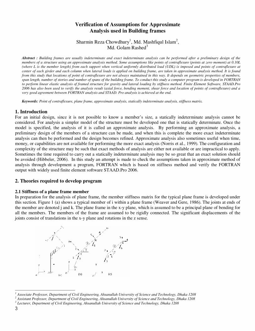
In preparation for the analysis of plane frame, the member stiffness matrix for the typical plane frame is developed under
this section. Figure 1 (a) shows a typical member of i within a plane frame (Weaver and Gere, 1986). The joints at ends of
the member are denoted j and k. The plane frame in the x-y plane, which is assumed to be a principal plane of bending for all the members. The members of the frame are assumed to be rigidly connected. The significant displacements of the
joints consist of translations in the x-y plane and rotations in the z sense.
1 Associate Professor, Department of Civil Engineering, Ahsanullah University of Science and Technology, Dhaka 1208
2 Assistant Professor, Department of Civil Engineering, Ahsanullah University of Science and Technology, Dhaka 1208
3 Lecturer, Department of Civil Engineering, Ahsanullah University of Science and Technology, Dhaka 1208
4
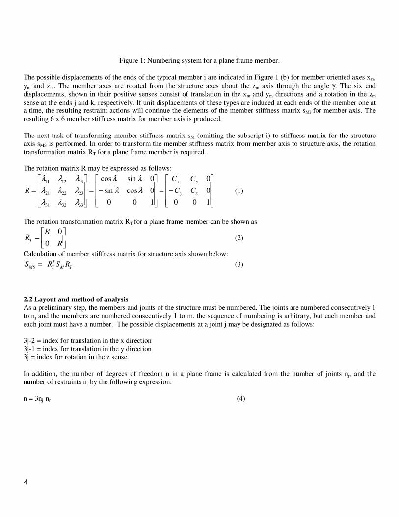
Figure 1: Numbering system for a plane frame member.
The possible displacements of the ends of the typical member i are indicated in Figure 1 (b) for member oriented axes xm,
ym and zm. The member axes are rotated from the structure axes about the zm axis through the angle γ. The six end displacements, shown in their positive senses consist of translation in the xm and ym directions and a rotation in the zm
sense at the ends j and k, respectively. If unit displacements of these types are induced at each ends of the member one at a time, the resulting restraint actions will continue the elements of the member stiffness matrix sMi for member axis. The
resulting 6 x 6 member stiffness matrix for member axis is produced.
The next task of transforming member stiffness matrix sM (omitting the subscript i) to stiffness matrix for the structure axis sMS is performed. In order to transform the member stiffness matrix from member axis to structure axis, the rotation
transformation matrix RT for a plane frame member is required.
The rotation matrix R may be expressed as follows:
−=
−=
=
100
0
0
100
0cossin
0sincos
333231
232221
131211
xy
yx
CC
CC
R λλ
λλ
λλλ
λλλ
λλλ
(1)
The rotation transformation matrix RT for a plane frame member can be shown as
=
R
RRT
0
0 (2)
Calculation of member stiffness matrix for structure axis shown below:
TM
T
TMSRSRS = (3)
2.2 Layout and method of analysis
As a preliminary step, the members and joints of the structure must be numbered. The joints are numbered consecutively 1 to nj and the members are numbered consecutively 1 to m. the sequence of numbering is arbitrary, but each member and
each joint must have a number. The possible displacements at a joint j may be designated as follows:
3j-2 = index for translation in the x direction
3j-1 = index for translation in the y direction
3j = index for rotation in the z sense.
In addition, the number of degrees of freedom n in a plane frame is calculated from the number of joints nj, and the
number of restraints nr by the following expression:
n = 3nj-nr (4)
5
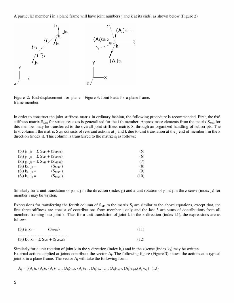
A particular member i in a plane frame will have joint numbers j and k at its ends, as shown below (Figure 2)
Figure 2: End-displacement for plane
frame member.
Figure 3: Joint loads for a plane frame.
In order to construct the joint stiffness matrix in ordinary fashion, the following procedure is recommended. First, the 6x6
stiffness matrix SMSi for structures axes is generalized for the i-th member. Approximate elements from the matrix SMSi for this member may be transferred to the overall joint stiffness matrix Sj through an organized handling of subscripts. The
first column I the matrix SMSi consists of restraint actions at j and k due to unit translation at the j end of member i in the x
direction (index i). This column is transferred to the matrix sj as follows:
(Sj) j1, j1 = Σ SMS + (SMS11)i (5)
(Sj) j2, j1 = Σ SMS + (SMS21)i (6)
(Sj) j3, j1 = Σ SMS + (SMS31)i (7) (Sj) k1, j1 = (SMS41)i (8)
(Sj) k2, j1 = (SMS51)i (9)
(Sj) k3, j1 = (SMS61)i (10)
Similarly for a unit translation of joint j in the direction (index j2) and a unit rotation of joint j in the z sense (index j3) for
member i may be written.
Expressions for transferring the fourth column of SMS to the matrix Sj are similar to the above equations, except that, the
first three stiffness are consist of contributions from member i only and the last 3 are sums of contributions from all members framing into joint k. Thus for a unit translation of joint k in the x direction (index k1), the expressions are as
follows:
(Sj) j1,k1 = (SMS14)i (11) ………………………………
(Sj) k3, k1 = Σ SMS + (SMS64)I (12)
Similarly for a unit rotation of joint k in the y direction (index k2) and in the z sense (index k3) may be written. External actions applied at joints contribute the vector Aj. The following figure (Figure 3) shows the actions at a typical
joint k in a plane frame. The vector Aj will take the following form:
Aj = {(Aj)1, (Aj)2, (Aj)3…., (Aj)3k-2, (Aj)3k-1, (Aj)3k, …., (Aj)3nj-2, (Aj)3nj-1,(Aj)3nj} (13)
6
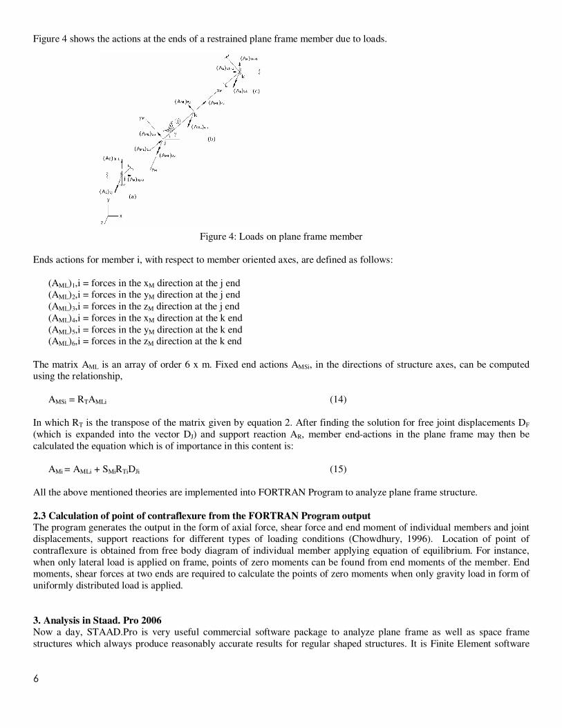
Figure 4 shows the actions at the ends of a restrained plane frame member due to loads.
Figure 4: Loads on plane frame member
Ends actions for member i, with respect to member oriented axes, are defined as follows:
(AML)1,i = forces in the xM direction at the j end (AML)2,i = forces in the yM direction at the j end
(AML)3,i = forces in the zM direction at the j end
(AML)4,i = forces in the xM direction at the k end
(AML)5,i = forces in the yM direction at the k end (AML)6,i = forces in the zM direction at the k end
The matrix AML is an array of order 6 x m. Fixed end actions AMSi, in the directions of structure axes, can be computed using the relationship,
AMSi = RTAMLi (14)
In which RT is the transpose of the matrix given by equation 2. After finding the solution for free joint displacements DF
(which is expanded into the vector DJ) and support reaction AR, member end-actions in the plane frame may then be
calculated the equation which is of importance in this content is:
AMi = AMLi + SMiRTiDJi (15)
All the above mentioned theories are implemented into FORTRAN Program to analyze plane frame structure.
2.3 Calculation of point of contraflexure from the FORTRAN Program output
The program generates the output in the form of axial force, shear force and end moment of individual members and joint displacements, support reactions for different types of loading conditions (Chowdhury, 1996). Location of point of
contraflexure is obtained from free body diagram of individual member applying equation of equilibrium. For instance,
when only lateral load is applied on frame, points of zero moments can be found from end moments of the member. End moments, shear forces at two ends are required to calculate the points of zero moments when only gravity load in form of
uniformly distributed load is applied.
3. Analysis in Staad. Pro 2006
Now a day, STAAD.Pro is very useful commercial software package to analyze plane frame as well as space frame
structures which always produce reasonably accurate results for regular shaped structures. It is Finite Element software
7
where numerical analysis is performed in an easy and quick way. Member end forces and moments in the member
resulting from loads applied to the structure in the STAAD.Pro 2006 environment are shown in Figure 5.
Figure 5: Member end forces and moments in STAAD.Pro 2006 environment (Bentley Systems Incorporated, 2006)
4. Problem Statement
Two-storied building with two bays is preliminary set for this study. All column and beam dimensions are fixed as 12inch x18inch and span and story height is 10ft. Beam, column numbering, lateral and uniformly distributed load arrangements
are shown in Figure 6. Beam depth, span length, storey height, storey number and number of spans has been varied which
is described in details in section 6.
(a) (b)
Figure 6: Plane Frames (a) with lateral load (b) with uniformly distribute load (UDL).
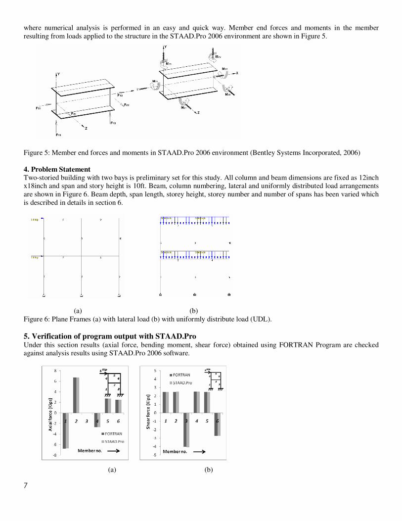
5. Verification of program output with STAAD.Pro Under this section results (axial force, bending moment, shear force) obtained using FORTRAN Program are checked against analysis results using STAAD.Pro 2006 software.
(a) (b)
8
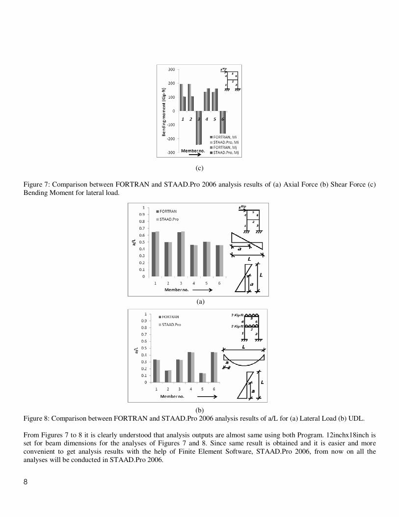
(c)
Figure 7: Comparison between FORTRAN and STAAD.Pro 2006 analysis results of (a) Axial Force (b) Shear Force (c)
Bending Moment for lateral load.
(a)
(b) Figure 8: Comparison between FORTRAN and STAAD.Pro 2006 analysis results of a/L for (a) Lateral Load (b) UDL.
From Figures 7 to 8 it is clearly understood that analysis outputs are almost same using both Program. 12inchx18inch is set for beam dimensions for the analyses of Figures 7 and 8. Since same result is obtained and it is easier and more
convenient to get analysis results with the help of Finite Element Software, STAAD.Pro 2006, from now on all the
analyses will be conducted in STAAD.Pro 2006.
9
6. Results and Discussion Parametric study are conducted under this section to see the variation of location of point of contraflexure changing beam
depth, span length, and storey height as well as increasing number of spans and stories in either symmetrical or non-symmetrical way. Each of these factors which control the location of point of contraflexure is described in the following
subsections one by one.
6.1 For two stories, two bays with same storey height and span length
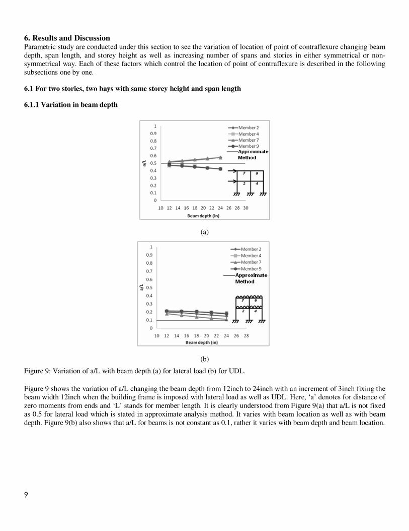
6.1.1 Variation in beam depth
(a)
(b)
Figure 9: Variation of a/L with beam depth (a) for lateral load (b) for UDL.
Figure 9 shows the variation of a/L changing the beam depth from 12inch to 24inch with an increment of 3inch fixing the beam width 12inch when the building frame is imposed with lateral load as well as UDL. Here, ‘a’ denotes for distance of
zero moments from ends and ‘L’ stands for member length. It is clearly understood from Figure 9(a) that a/L is not fixed
as 0.5 for lateral load which is stated in approximate analysis method. It varies with beam location as well as with beam
depth. Figure 9(b) also shows that a/L for beams is not constant as 0.1, rather it varies with beam depth and beam location.
10
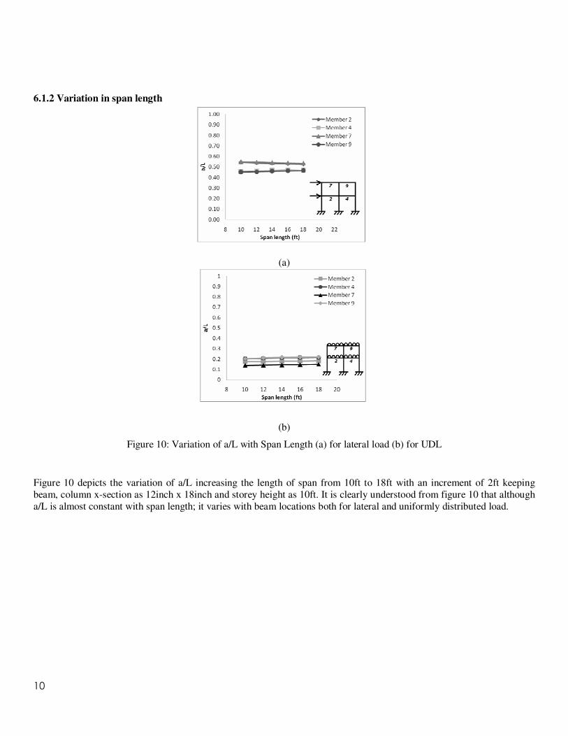
6.1.2 Variation in span length
(a)
(b)
Figure 10: Variation of a/L with Span Length (a) for lateral load (b) for UDL
Figure 10 depicts the variation of a/L increasing the length of span from 10ft to 18ft with an increment of 2ft keeping
beam, column x-section as 12inch x 18inch and storey height as 10ft. It is clearly understood from figure 10 that although
a/L is almost constant with span length; it varies with beam locations both for lateral and uniformly distributed load.
11
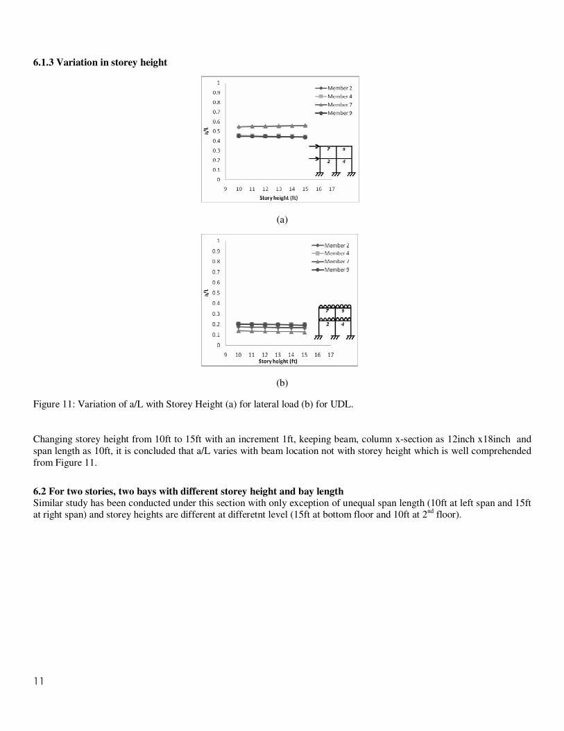
6.1.3 Variation in storey height
(a)
(b)
Figure 11: Variation of a/L with Storey Height (a) for lateral load (b) for UDL.
Changing storey height from 10ft to 15ft with an increment 1ft, keeping beam, column x-section as 12inch x18inch and
span length as 10ft, it is concluded that a/L varies with beam location not with storey height which is well comprehended
from Figure 11.
6.2 For two stories, two bays with different storey height and bay length
Similar study has been conducted under this section with only exception of unequal span length (10ft at left span and 15ft at right span) and storey heights are different at differetnt level (15ft at bottom floor and 10ft at 2
nd floor).
12
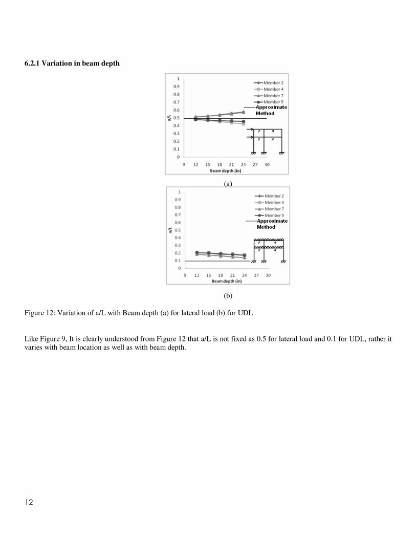
6.2.1 Variation in beam depth
Figure 12: Variation of a/L with Beam depth (a) for lateral load (b) for UDL
Like Figure 9, It is clearly understood from Figure 12 that a/L is not fixed as 0.5 for lateral load and 0.1 for UDL, rather it varies with beam location as well as with beam depth.
(a)
(b)
13
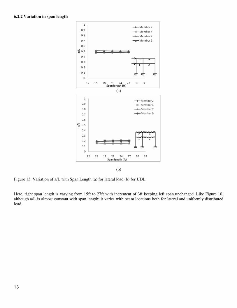
6.2.2 Variation in span length
(a)
(b)
Figure 13: Variation of a/L with Span Length (a) for lateral load (b) for UDL.
Here, right span length is varying from 15ft to 27ft with increment of 3ft keeping left span unchanged. Like Figure 10,
although a/L is almost constant with span length; it varies with beam locations both for lateral and uniformly distributed
load.
14
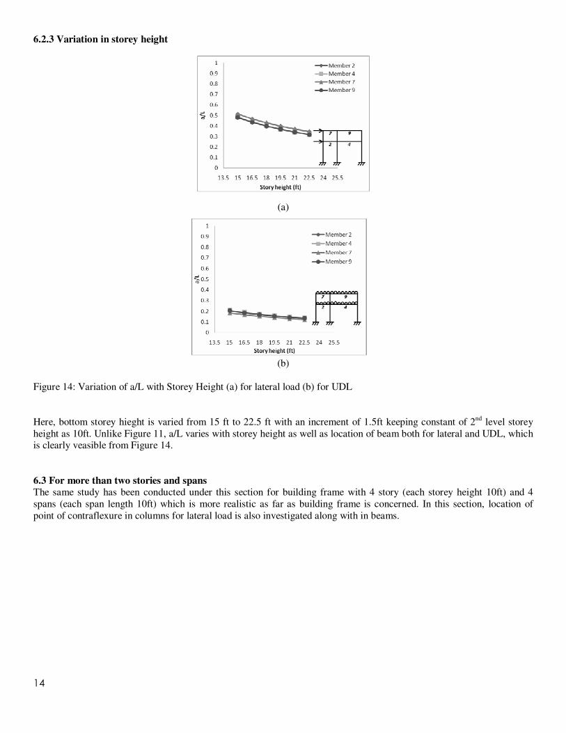
6.2.3 Variation in storey height
(a)
(b)
Figure 14: Variation of a/L with Storey Height (a) for lateral load (b) for UDL
Here, bottom storey hieght is varied from 15 ft to 22.5 ft with an increment of 1.5ft keeping constant of 2nd
level storey
height as 10ft. Unlike Figure 11, a/L varies with storey height as well as location of beam both for lateral and UDL, which is clearly veasible from Figure 14.
6.3 For more than two stories and spans
The same study has been conducted under this section for building frame with 4 story (each storey height 10ft) and 4
spans (each span length 10ft) which is more realistic as far as building frame is concerned. In this section, location of
point of contraflexure in columns for lateral load is also investigated along with in beams.
15
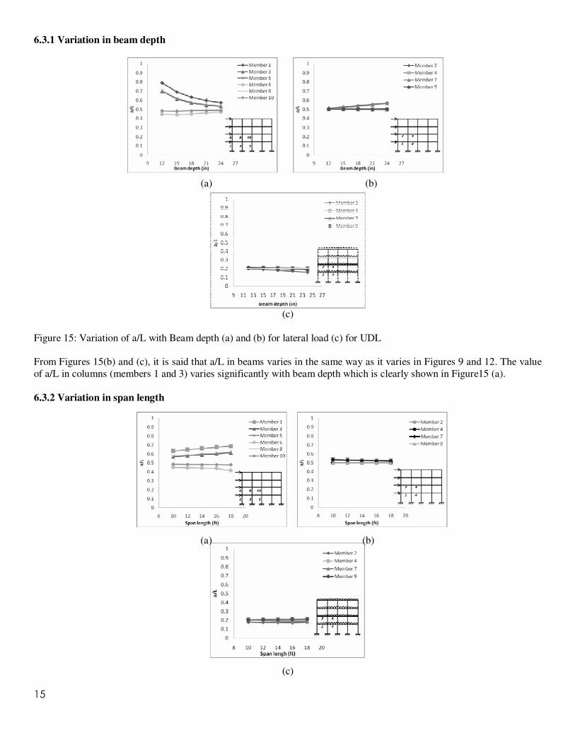
6.3.1 Variation in beam depth
(a) (b)
(c)
Figure 15: Variation of a/L with Beam depth (a) and (b) for lateral load (c) for UDL
From Figures 15(b) and (c), it is said that a/L in beams varies in the same way as it varies in Figures 9 and 12. The value
of a/L in columns (members 1 and 3) varies significantly with beam depth which is clearly shown in Figure15 (a).
6.3.2 Variation in span length
(a) (b)
(c)
16
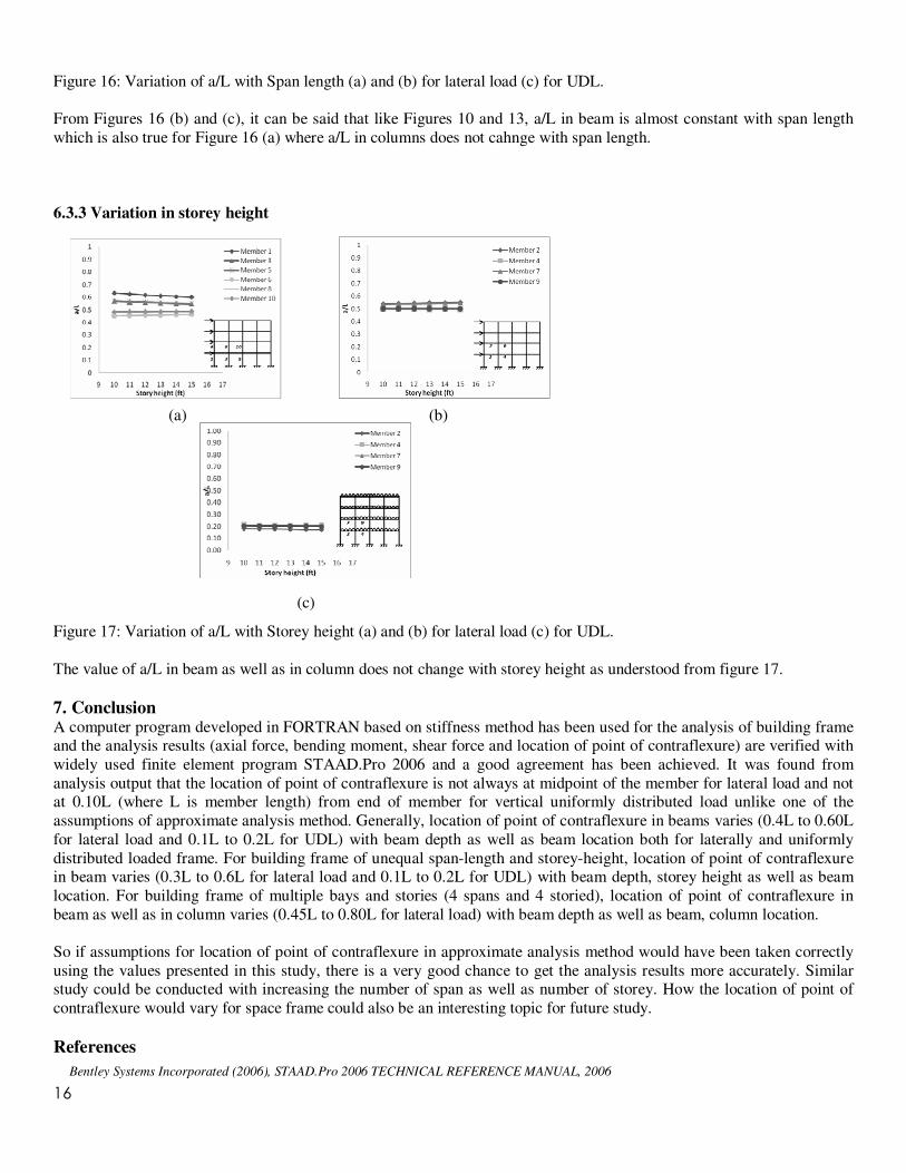
Figure 16: Variation of a/L with Span length (a) and (b) for lateral load (c) for UDL.
From Figures 16 (b) and (c), it can be said that like Figures 10 and 13, a/L in beam is almost constant with span length
which is also true for Figure 16 (a) where a/L in columns does not cahnge with span length.
6.3.3 Variation in storey height
(a) (b)
(c)
Figure 17: Variation of a/L with Storey height (a) and (b) for lateral load (c) for UDL.
The value of a/L in beam as well as in column does not change with storey height as understood from figure 17.
7. Conclusion A computer program developed in FORTRAN based on stiffness method has been used for the analysis of building frame and the analysis results (axial force, bending moment, shear force and location of point of contraflexure) are verified with
widely used finite element program STAAD.Pro 2006 and a good agreement has been achieved. It was found from
analysis output that the location of point of contraflexure is not always at midpoint of the member for lateral load and not at 0.10L (where L is member length) from end of member for vertical uniformly distributed load unlike one of the
assumptions of approximate analysis method. Generally, location of point of contraflexure in beams varies (0.4L to 0.60L
for lateral load and 0.1L to 0.2L for UDL) with beam depth as well as beam location both for laterally and uniformly
distributed loaded frame. For building frame of unequal span-length and storey-height, location of point of contraflexure in beam varies (0.3L to 0.6L for lateral load and 0.1L to 0.2L for UDL) with beam depth, storey height as well as beam
location. For building frame of multiple bays and stories (4 spans and 4 storied), location of point of contraflexure in
beam as well as in column varies (0.45L to 0.80L for lateral load) with beam depth as well as beam, column location.
So if assumptions for location of point of contraflexure in approximate analysis method would have been taken correctly
using the values presented in this study, there is a very good chance to get the analysis results more accurately. Similar study could be conducted with increasing the number of span as well as number of storey. How the location of point of
contraflexure would vary for space frame could also be an interesting topic for future study.
References
Bentley Systems Incorporated (2006), STAAD.Pro 2006 TECHNICAL REFERENCE MANUAL, 2006

17
Chowdhury, S.R. “Comparison between Space Frame and Plane Frame Analysis”, Undergraduate Thesis, Department of Civil Engineering,
BUET, 1996.
Coats, R.C. Coutie, M.G. and Kong, F.R. “Structural Analysis”, 2nd
Edition, Van Nostrand Reinhold Company, UK, 1980
Greene, B.E. “Application of Generalized Constraints in the Stiffness Method of Structure Analysis”, AIAA Jour, Volume 4, No. 9, Sept. 1966
Hibbeler, R.C. “Structural Analysis”, Sixth Edition, Pearson, Prentice Hall, 2006
Jennings, A. “Matrix Computation For Engineers and Scientists”, Johm Wiley and Sons, 1980.
Norris, C.H., Wilbur, J.B. and Utku, S. “Elementary Structural Analysis”, Fourth Edition, McGraw-Hill Inc., 1991
Weaver, W.JR. and Gere, J.M. “Matrix Analysis of Framed Structures”, 2nd
Edition, Van Nostrand Reinhold Company, USA, 1986