Embed Size (px)
Citation preview
Chapter 5 Gate-Level Modeling 1
Verilog HDL:Digital Design and Modeling
Chapter 5
Gate-Level Modeling
Chapter 5 Gate-Level Modeling 2
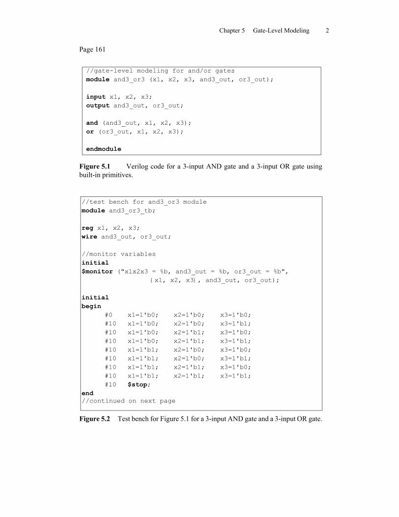
Page 161
//gate-level modeling for and/or gates module and3_or3 (x1, x2, x3, and3_out, or3_out);
input x1, x2, x3; output and3_out, or3_out;
and (and3_out, x1, x2, x3); or (or3_out, x1, x2, x3);
endmodule
Figure 5.1 Verilog code for a 3-input AND gate and a 3-input OR gate usingbuilt-in primitives.
//test bench for and3_or3 modulemodule and3_or3_tb;
reg x1, x2, x3;wire and3_out, or3_out;
//monitor variablesinitial$monitor ("x1x2x3 = %b, and3_out = %b, or3_out = %b",
{x1, x2, x3}, and3_out, or3_out);
initialbegin
#0 x1=1'b0; x2=1'b0; x3=1'b0;#10 x1=1'b0; x2=1'b0; x3=1'b1;#10 x1=1'b0; x2=1'b1; x3=1'b0;#10 x1=1'b0; x2=1'b1; x3=1'b1;#10 x1=1'b1; x2=1'b0; x3=1'b0;#10 x1=1'b1; x2=1'b0; x3=1'b1;#10 x1=1'b1; x2=1'b1; x3=1'b0;#10 x1=1'b1; x2=1'b1; x3=1'b1;#10 $stop;
end//continued on next page
Figure 5.2 Test bench for Figure 5.1 for a 3-input AND gate and a 3-input OR gate.
Chapter 5 Gate-Level Modeling 3
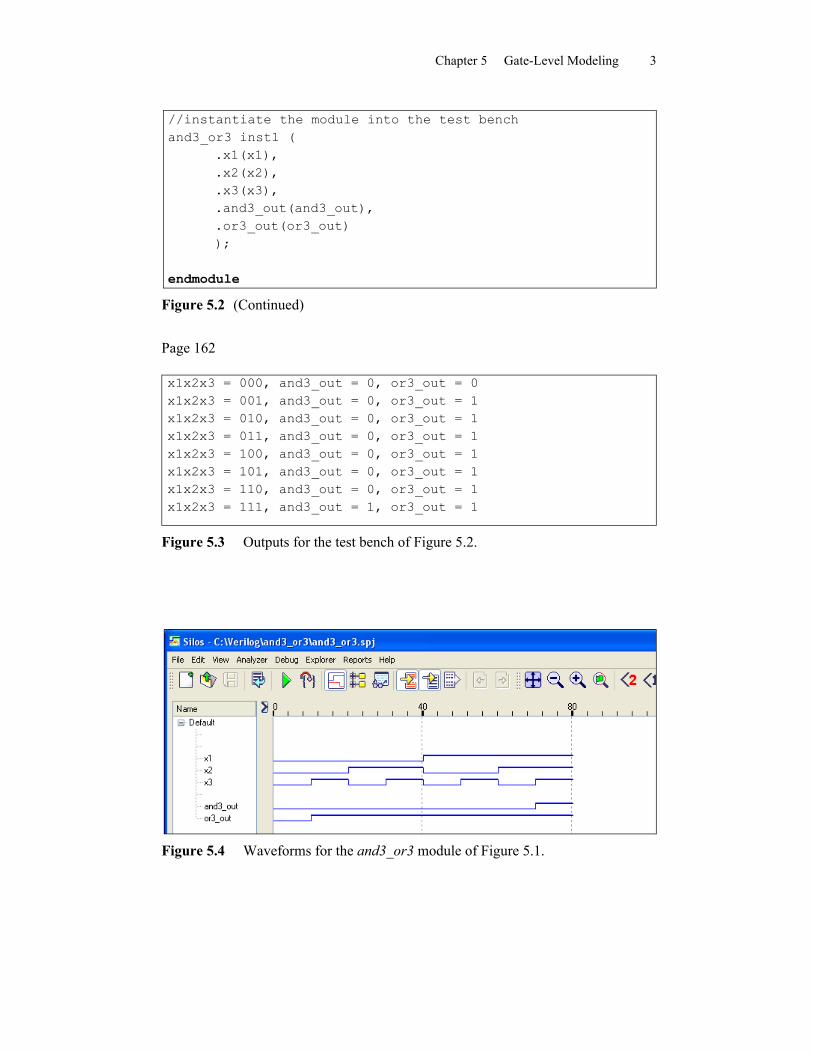
//instantiate the module into the test benchand3_or3 inst1 (
.x1(x1),
.x2(x2),
.x3(x3),
.and3_out(and3_out),
.or3_out(or3_out));
endmodule
Figure 5.2 (Continued)
Page 162
x1x2x3 = 000, and3_out = 0, or3_out = 0x1x2x3 = 001, and3_out = 0, or3_out = 1x1x2x3 = 010, and3_out = 0, or3_out = 1x1x2x3 = 011, and3_out = 0, or3_out = 1x1x2x3 = 100, and3_out = 0, or3_out = 1x1x2x3 = 101, and3_out = 0, or3_out = 1x1x2x3 = 110, and3_out = 0, or3_out = 1x1x2x3 = 111, and3_out = 1, or3_out = 1
Figure 5.3 Outputs for the test bench of Figure 5.2.
Figure 5.4 Waveforms for the and3_or3 module of Figure 5.1.
Chapter 5 Gate-Level Modeling 4
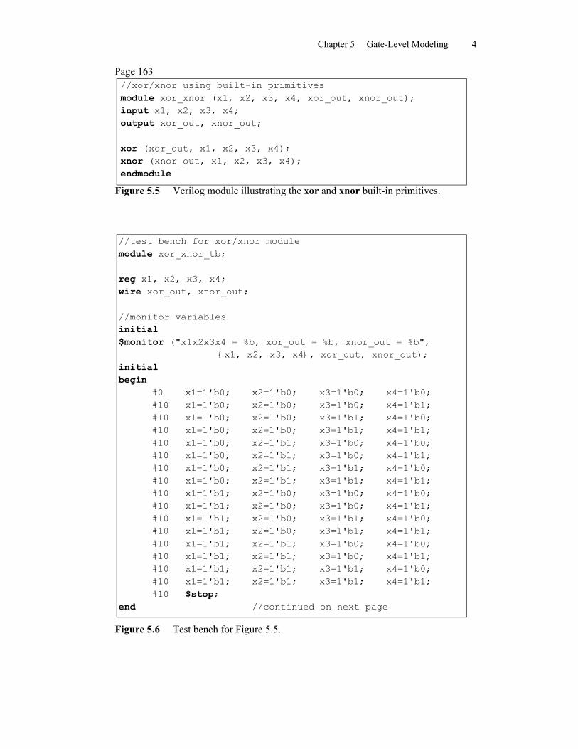
Page 163//xor/xnor using built-in primitivesmodule xor_xnor (x1, x2, x3, x4, xor_out, xnor_out);input x1, x2, x3, x4;output xor_out, xnor_out;
xor (xor_out, x1, x2, x3, x4);xnor (xnor_out, x1, x2, x3, x4);endmodule
Figure 5.5 Verilog module illustrating the xor and xnor built-in primitives.
//test bench for xor/xnor modulemodule xor_xnor_tb;
reg x1, x2, x3, x4;wire xor_out, xnor_out;
//monitor variablesinitial$monitor ("x1x2x3x4 = %b, xor_out = %b, xnor_out = %b",
{x1, x2, x3, x4}, xor_out, xnor_out);initialbegin
#0 x1=1'b0; x2=1'b0; x3=1'b0; x4=1'b0;#10 x1=1'b0; x2=1'b0; x3=1'b0; x4=1'b1;#10 x1=1'b0; x2=1'b0; x3=1'b1; x4=1'b0;#10 x1=1'b0; x2=1'b0; x3=1'b1; x4=1'b1;#10 x1=1'b0; x2=1'b1; x3=1'b0; x4=1'b0;#10 x1=1'b0; x2=1'b1; x3=1'b0; x4=1'b1;#10 x1=1'b0; x2=1'b1; x3=1'b1; x4=1'b0;#10 x1=1'b0; x2=1'b1; x3=1'b1; x4=1'b1;#10 x1=1'b1; x2=1'b0; x3=1'b0; x4=1'b0;#10 x1=1'b1; x2=1'b0; x3=1'b0; x4=1'b1;#10 x1=1'b1; x2=1'b0; x3=1'b1; x4=1'b0;#10 x1=1'b1; x2=1'b0; x3=1'b1; x4=1'b1;#10 x1=1'b1; x2=1'b1; x3=1'b0; x4=1'b0;#10 x1=1'b1; x2=1'b1; x3=1'b0; x4=1'b1;#10 x1=1'b1; x2=1'b1; x3=1'b1; x4=1'b0;#10 x1=1'b1; x2=1'b1; x3=1'b1; x4=1'b1;#10 $stop;
end //continued on next page
Figure 5.6 Test bench for Figure 5.5.
Chapter 5 Gate-Level Modeling 5
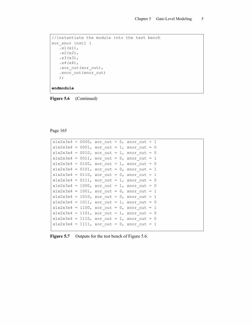
//instantiate the module into the test benchxor_xnor inst1 (
.x1(x1),
.x2(x2),
.x3(x3),
.x4(x4),
.xor_out(xor_out),
.xnor_out(xnor_out));
endmodule
Figure 5.6 (Continued)
Page 165
x1x2x3x4 = 0000, xor_out = 0, xnor_out = 1x1x2x3x4 = 0001, xor_out = 1, xnor_out = 0x1x2x3x4 = 0010, xor_out = 1, xnor_out = 0x1x2x3x4 = 0011, xor_out = 0, xnor_out = 1x1x2x3x4 = 0100, xor_out = 1, xnor_out = 0x1x2x3x4 = 0101, xor_out = 0, xnor_out = 1x1x2x3x4 = 0110, xor_out = 0, xnor_out = 1x1x2x3x4 = 0111, xor_out = 1, xnor_out = 0x1x2x3x4 = 1000, xor_out = 1, xnor_out = 0x1x2x3x4 = 1001, xor_out = 0, xnor_out = 1x1x2x3x4 = 1010, xor_out = 0, xnor_out = 1x1x2x3x4 = 1011, xor_out = 1, xnor_out = 0x1x2x3x4 = 1100, xor_out = 0, xnor_out = 1x1x2x3x4 = 1101, xor_out = 1, xnor_out = 0x1x2x3x4 = 1110, xor_out = 1, xnor_out = 0x1x2x3x4 = 1111, xor_out = 0, xnor_out = 1
Figure 5.7 Outputs for the test bench of Figure 5.6.
Chapter 5 Gate-Level Modeling 6
Page 165
Figure 5.8 Waveforms for the xor_xnor module of Figure 5.5.
Page 167
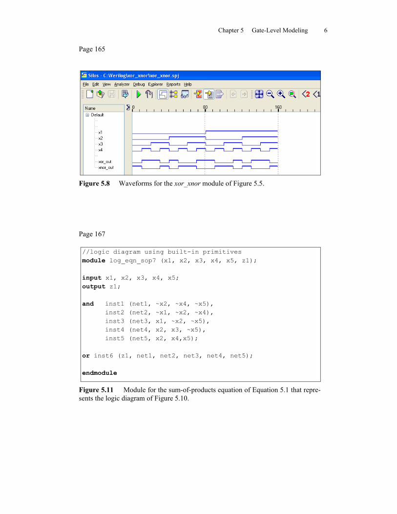
//logic diagram using built-in primitivesmodule log_eqn_sop7 (x1, x2, x3, x4, x5, z1);
input x1, x2, x3, x4, x5;output z1;
and inst1 (net1, ~x2, ~x4, ~x5),inst2 (net2, ~x1, ~x2, ~x4),inst3 (net3, x1, ~x2, ~x5),inst4 (net4, x2, x3, ~x5),inst5 (net5, x2, x4,x5);
or inst6 (z1, net1, net2, net3, net4, net5);
endmodule
Figure 5.11 Module for the sum-of-products equation of Equation 5.1 that repre-sents the logic diagram of Figure 5.10.
Chapter 5 Gate-Level Modeling 7
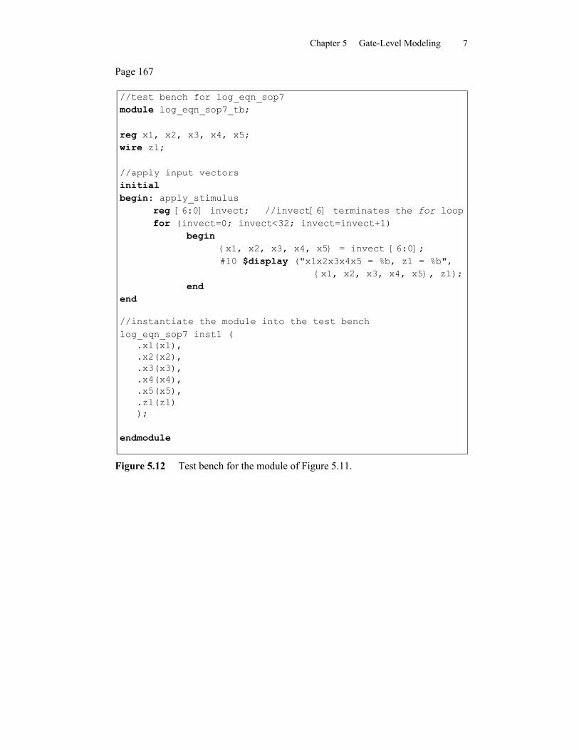
Page 167
//test bench for log_eqn_sop7module log_eqn_sop7_tb;
reg x1, x2, x3, x4, x5;wire z1;
//apply input vectorsinitialbegin: apply_stimulus
reg [6:0] invect; //invect[6] terminates the for loopfor (invect=0; invect<32; invect=invect+1)
begin{x1, x2, x3, x4, x5} = invect [6:0];#10 $display ("x1x2x3x4x5 = %b, z1 = %b",
{x1, x2, x3, x4, x5}, z1);end
end
//instantiate the module into the test benchlog_eqn_sop7 inst1 (
.x1(x1),
.x2(x2),
.x3(x3),
.x4(x4),
.x5(x5),
.z1(z1));
endmodule
Figure 5.12 Test bench for the module of Figure 5.11.
Chapter 5 Gate-Level Modeling 8
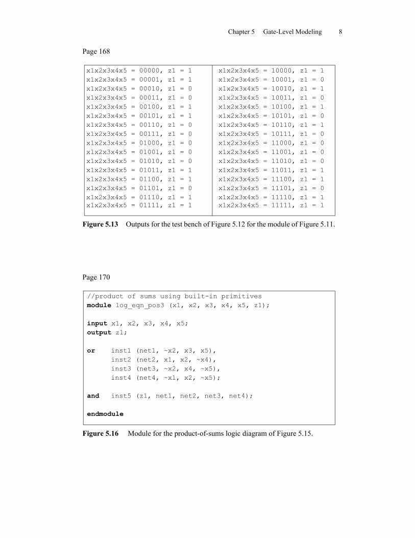
Page 168
x1x2x3x4x5 = 00000, z1 = 1x1x2x3x4x5 = 00001, z1 = 1x1x2x3x4x5 = 00010, z1 = 0x1x2x3x4x5 = 00011, z1 = 0x1x2x3x4x5 = 00100, z1 = 1x1x2x3x4x5 = 00101, z1 = 1x1x2x3x4x5 = 00110, z1 = 0x1x2x3x4x5 = 00111, z1 = 0x1x2x3x4x5 = 01000, z1 = 0x1x2x3x4x5 = 01001, z1 = 0x1x2x3x4x5 = 01010, z1 = 0x1x2x3x4x5 = 01011, z1 = 1x1x2x3x4x5 = 01100, z1 = 1x1x2x3x4x5 = 01101, z1 = 0x1x2x3x4x5 = 01110, z1 = 1x1x2x3x4x5 = 01111, z1 = 1
x1x2x3x4x5 = 10000, z1 = 1x1x2x3x4x5 = 10001, z1 = 0x1x2x3x4x5 = 10010, z1 = 1x1x2x3x4x5 = 10011, z1 = 0x1x2x3x4x5 = 10100, z1 = 1x1x2x3x4x5 = 10101, z1 = 0x1x2x3x4x5 = 10110, z1 = 1x1x2x3x4x5 = 10111, z1 = 0x1x2x3x4x5 = 11000, z1 = 0x1x2x3x4x5 = 11001, z1 = 0x1x2x3x4x5 = 11010, z1 = 0x1x2x3x4x5 = 11011, z1 = 1x1x2x3x4x5 = 11100, z1 = 1x1x2x3x4x5 = 11101, z1 = 0x1x2x3x4x5 = 11110, z1 = 1x1x2x3x4x5 = 11111, z1 = 1
Figure 5.13 Outputs for the test bench of Figure 5.12 for the module of Figure 5.11.
Page 170
//product of sums using built-in primitivesmodule log_eqn_pos3 (x1, x2, x3, x4, x5, z1);
input x1, x2, x3, x4, x5;output z1;
or inst1 (net1, ~x2, x3, x5),inst2 (net2, x1, x2, ~x4),inst3 (net3, ~x2, x4, ~x5),inst4 (net4, ~x1, x2, ~x5);
and inst5 (z1, net1, net2, net3, net4);
endmodule
Figure 5.16 Module for the product-of-sums logic diagram of Figure 5.15.
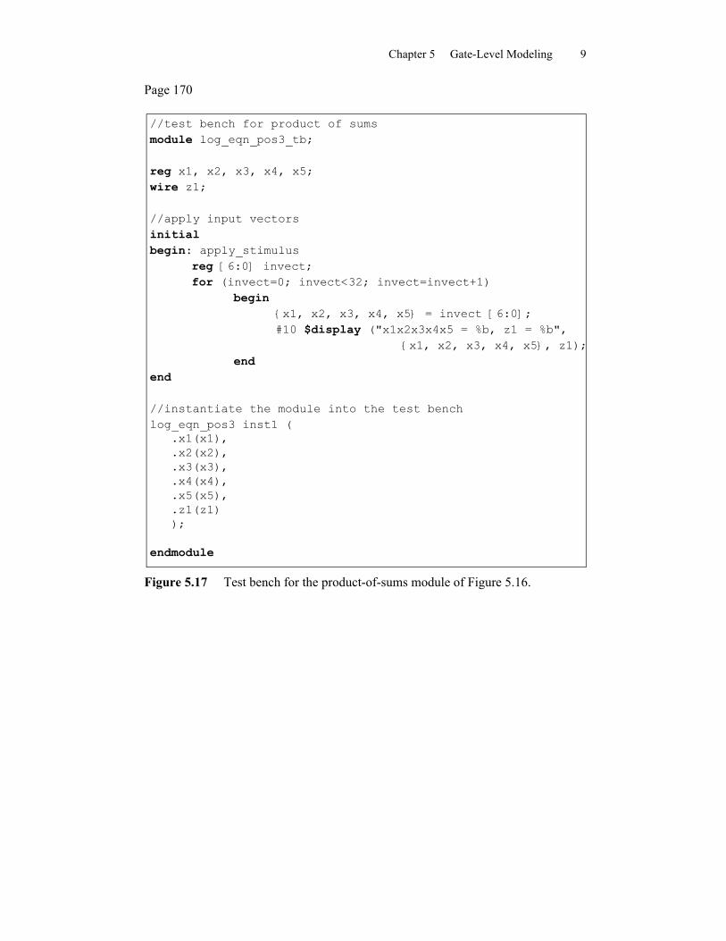
Chapter 5 Gate-Level Modeling 9
Page 170
//test bench for product of sumsmodule log_eqn_pos3_tb;
reg x1, x2, x3, x4, x5;wire z1;
//apply input vectorsinitialbegin: apply_stimulus
reg [6:0] invect;for (invect=0; invect<32; invect=invect+1)
begin{x1, x2, x3, x4, x5} = invect [6:0];#10 $display ("x1x2x3x4x5 = %b, z1 = %b",
{x1, x2, x3, x4, x5}, z1);end
end
//instantiate the module into the test benchlog_eqn_pos3 inst1 (
.x1(x1),
.x2(x2),
.x3(x3),
.x4(x4),
.x5(x5),
.z1(z1));
endmodule
Figure 5.17 Test bench for the product-of-sums module of Figure 5.16.
Chapter 5 Gate-Level Modeling 10
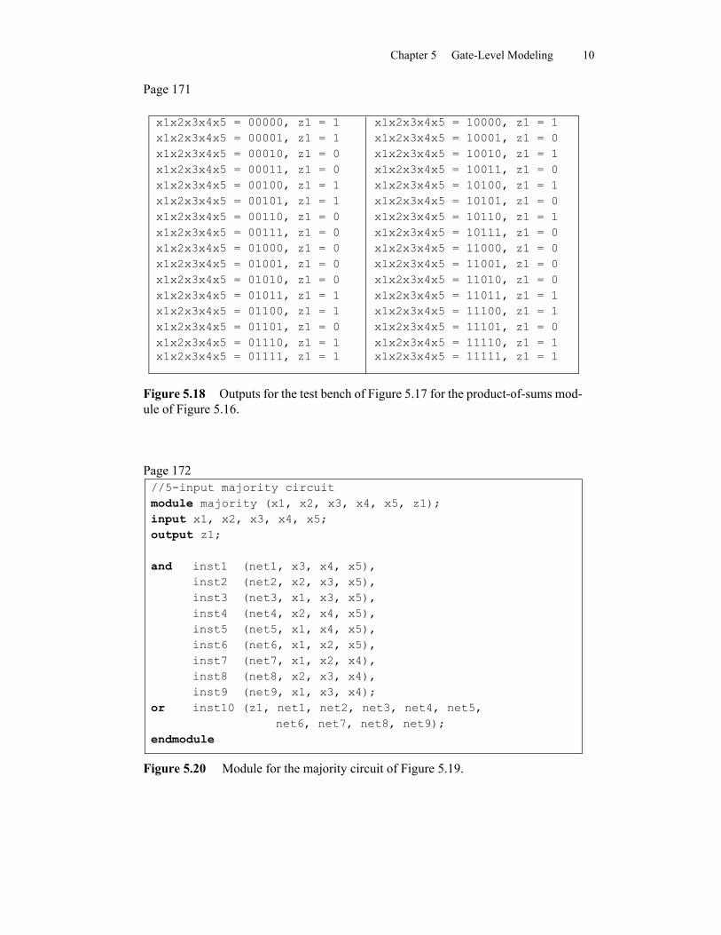
Page 171
x1x2x3x4x5 = 00000, z1 = 1 x1x2x3x4x5 = 00001, z1 = 1 x1x2x3x4x5 = 00010, z1 = 0 x1x2x3x4x5 = 00011, z1 = 0 x1x2x3x4x5 = 00100, z1 = 1 x1x2x3x4x5 = 00101, z1 = 1 x1x2x3x4x5 = 00110, z1 = 0 x1x2x3x4x5 = 00111, z1 = 0 x1x2x3x4x5 = 01000, z1 = 0 x1x2x3x4x5 = 01001, z1 = 0 x1x2x3x4x5 = 01010, z1 = 0 x1x2x3x4x5 = 01011, z1 = 1 x1x2x3x4x5 = 01100, z1 = 1 x1x2x3x4x5 = 01101, z1 = 0 x1x2x3x4x5 = 01110, z1 = 1 x1x2x3x4x5 = 01111, z1 = 1
x1x2x3x4x5 = 10000, z1 = 1x1x2x3x4x5 = 10001, z1 = 0x1x2x3x4x5 = 10010, z1 = 1x1x2x3x4x5 = 10011, z1 = 0x1x2x3x4x5 = 10100, z1 = 1x1x2x3x4x5 = 10101, z1 = 0x1x2x3x4x5 = 10110, z1 = 1x1x2x3x4x5 = 10111, z1 = 0x1x2x3x4x5 = 11000, z1 = 0x1x2x3x4x5 = 11001, z1 = 0x1x2x3x4x5 = 11010, z1 = 0x1x2x3x4x5 = 11011, z1 = 1x1x2x3x4x5 = 11100, z1 = 1x1x2x3x4x5 = 11101, z1 = 0x1x2x3x4x5 = 11110, z1 = 1x1x2x3x4x5 = 11111, z1 = 1
Figure 5.18 Outputs for the test bench of Figure 5.17 for the product-of-sums mod-ule of Figure 5.16.
//5-input majority circuitmodule majority (x1, x2, x3, x4, x5, z1);input x1, x2, x3, x4, x5;output z1;
and inst1 (net1, x3, x4, x5),inst2 (net2, x2, x3, x5),inst3 (net3, x1, x3, x5),inst4 (net4, x2, x4, x5),inst5 (net5, x1, x4, x5),inst6 (net6, x1, x2, x5),inst7 (net7, x1, x2, x4),inst8 (net8, x2, x3, x4),inst9 (net9, x1, x3, x4);
or inst10 (z1, net1, net2, net3, net4, net5,net6, net7, net8, net9);
endmodule
Page 172
Figure 5.20 Module for the majority circuit of Figure 5.19.
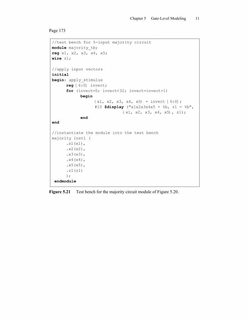
Chapter 5 Gate-Level Modeling 11
Page 173
//test bench for 5-input majority circuitmodule majority_tb;reg x1, x2, x3, x4, x5;wire z1;
//apply input vectorsinitialbegin: apply_stimulus
reg [6:0] invect;for (invect=0; invect<32; invect=invect+1)
begin{x1, x2, x3, x4, x5} = invect [6:0];#10 $display ("x1x2x3x4x5 = %b, z1 = %b",
{x1, x2, x3, x4, x5}, z1);end
end
//instantiate the module into the test benchmajority inst1 (
.x1(x1),
.x2(x2),
.x3(x3),
.x4(x4),
.x5(x5),
.z1(z1));
endmodule
Figure 5.21 Test bench for the majority circuit module of Figure 5.20.
Chapter 5 Gate-Level Modeling 12
Page 173
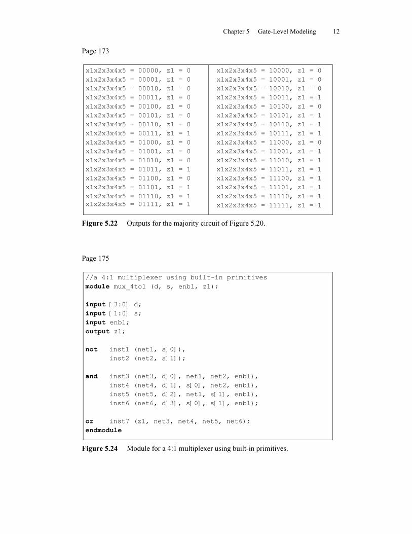
x1x2x3x4x5 = 00000, z1 = 0x1x2x3x4x5 = 00001, z1 = 0x1x2x3x4x5 = 00010, z1 = 0x1x2x3x4x5 = 00011, z1 = 0x1x2x3x4x5 = 00100, z1 = 0x1x2x3x4x5 = 00101, z1 = 0x1x2x3x4x5 = 00110, z1 = 0x1x2x3x4x5 = 00111, z1 = 1x1x2x3x4x5 = 01000, z1 = 0x1x2x3x4x5 = 01001, z1 = 0x1x2x3x4x5 = 01010, z1 = 0x1x2x3x4x5 = 01011, z1 = 1x1x2x3x4x5 = 01100, z1 = 0x1x2x3x4x5 = 01101, z1 = 1x1x2x3x4x5 = 01110, z1 = 1x1x2x3x4x5 = 01111, z1 = 1
x1x2x3x4x5 = 10000, z1 = 0x1x2x3x4x5 = 10001, z1 = 0x1x2x3x4x5 = 10010, z1 = 0x1x2x3x4x5 = 10011, z1 = 1x1x2x3x4x5 = 10100, z1 = 0x1x2x3x4x5 = 10101, z1 = 1x1x2x3x4x5 = 10110, z1 = 1x1x2x3x4x5 = 10111, z1 = 1x1x2x3x4x5 = 11000, z1 = 0x1x2x3x4x5 = 11001, z1 = 1x1x2x3x4x5 = 11010, z1 = 1x1x2x3x4x5 = 11011, z1 = 1x1x2x3x4x5 = 11100, z1 = 1x1x2x3x4x5 = 11101, z1 = 1x1x2x3x4x5 = 11110, z1 = 1x1x2x3x4x5 = 11111, z1 = 1
Figure 5.22 Outputs for the majority circuit of Figure 5.20.
Page 175
//a 4:1 multiplexer using built-in primitivesmodule mux_4to1 (d, s, enbl, z1);
input [3:0] d;input [1:0] s;input enbl;output z1;
not inst1 (net1, s[0]),inst2 (net2, s[1]);
and inst3 (net3, d[0], net1, net2, enbl),inst4 (net4, d[1], s[0], net2, enbl),inst5 (net5, d[2], net1, s[1], enbl),inst6 (net6, d[3], s[0], s[1], enbl);
or inst7 (z1, net3, net4, net5, net6);endmodule
Figure 5.24 Module for a 4:1 multiplexer using built-in primitives.
Chapter 5 Gate-Level Modeling 13
Page 175
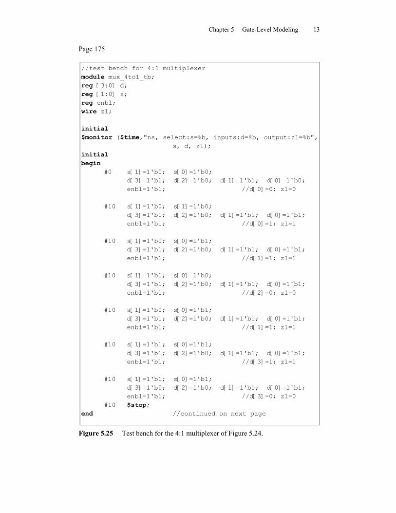
//test bench for 4:1 multiplexermodule mux_4to1_tb;reg [3:0] d;reg [1:0] s;reg enbl;wire z1;
initial$monitor ($time,"ns, select:s=%b, inputs:d=%b, output:z1=%b",
s, d, z1);initialbegin
#0 s[1]=1'b0; s[0]=1'b0;d[3]=1'b1; d[2]=1'b0; d[1]=1'b1; d[0]=1'b0;enbl=1'b1; //d[0]=0; z1=0
#10 s[1]=1'b0; s[1]=1'b0;d[3]=1'b1; d[2]=1'b0; d[1]=1'b1; d[0]=1'b1;enbl=1'b1; //d[0]=1; z1=1
#10 s[1]=1'b0; s[0]=1'b1;d[3]=1'b1; d[2]=1'b0; d[1]=1'b1; d[0]=1'b1;enbl=1'b1; //d[1]=1; z1=1
#10 s[1]=1'b1; s[0]=1'b0;d[3]=1'b1; d[2]=1'b0; d[1]=1'b1; d[0]=1'b1;enbl=1'b1; //d[2]=0; z1=0
#10 s[1]=1'b0; s[0]=1'b1;d[3]=1'b1; d[2]=1'b0; d[1]=1'b1; d[0]=1'b1;enbl=1'b1; //d[1]=1; z1=1
#10 s[1]=1'b1; s[0]=1'b1;d[3]=1'b1; d[2]=1'b0; d[1]=1'b1; d[0]=1'b1;enbl=1'b1; //d[3]=1; z1=1
#10 s[1]=1'b1; s[0]=1'b1;d[3]=1'b0; d[2]=1'b0; d[1]=1'b1; d[0]=1'b1;enbl=1'b1; //d[3]=0; z1=0
#10 $stop;end //continued on next page
Figure 5.25 Test bench for the 4:1 multiplexer of Figure 5.24.
Chapter 5 Gate-Level Modeling 14
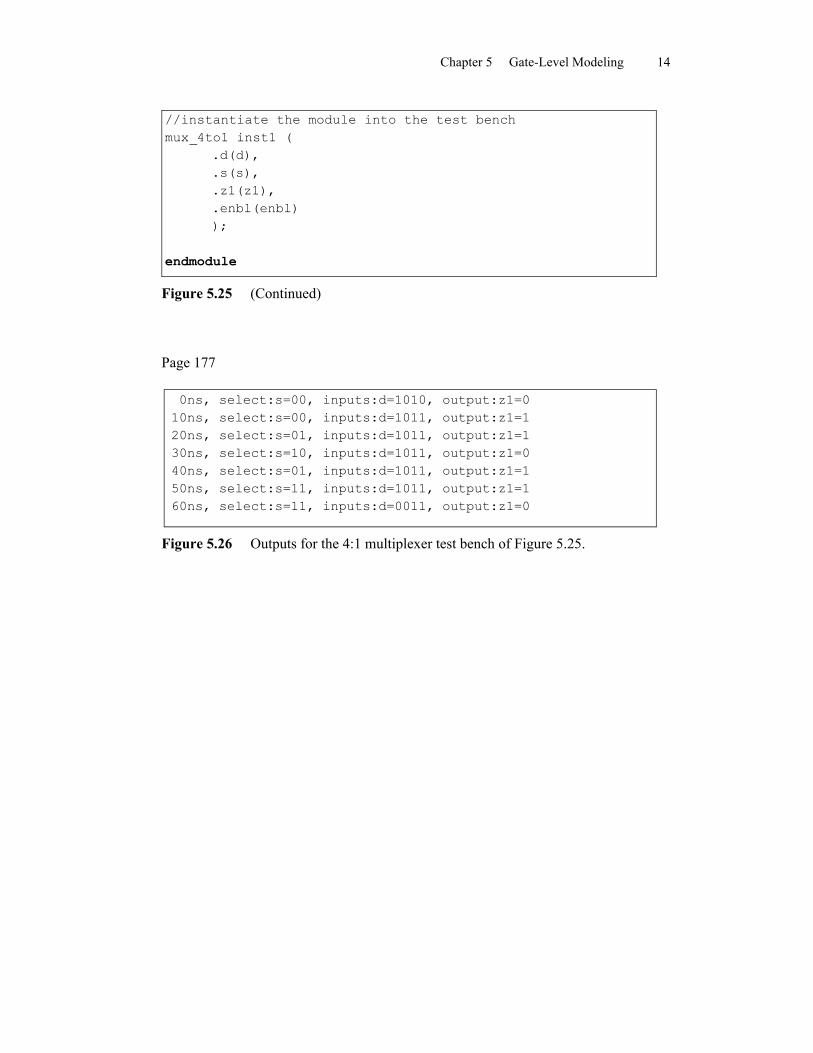
//instantiate the module into the test benchmux_4to1 inst1 (
.d(d),
.s(s),
.z1(z1),
.enbl(enbl));
endmodule
Figure 5.25 (Continued)
Page 177
0ns, select:s=00, inputs:d=1010, output:z1=010ns, select:s=00, inputs:d=1011, output:z1=120ns, select:s=01, inputs:d=1011, output:z1=130ns, select:s=10, inputs:d=1011, output:z1=040ns, select:s=01, inputs:d=1011, output:z1=150ns, select:s=11, inputs:d=1011, output:z1=160ns, select:s=11, inputs:d=0011, output:z1=0
Figure 5.26 Outputs for the 4:1 multiplexer test bench of Figure 5.25.
Chapter 5 Gate-Level Modeling 15
Page 178
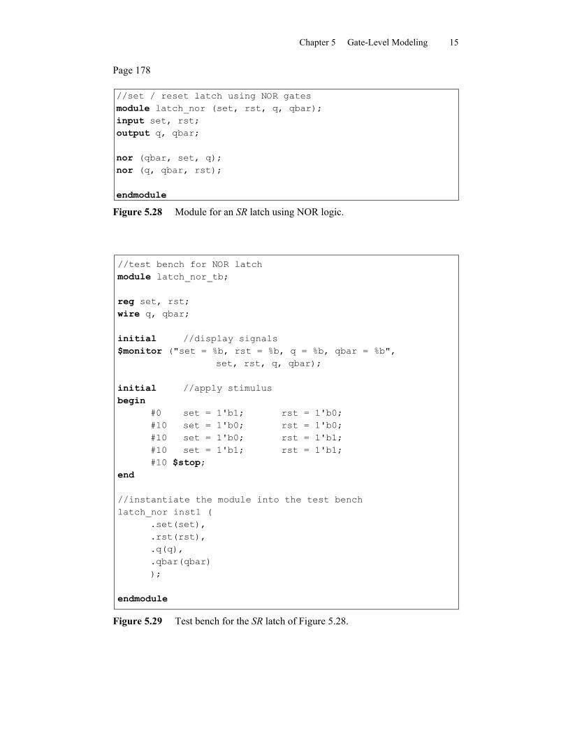
//set / reset latch using NOR gatesmodule latch_nor (set, rst, q, qbar);input set, rst;output q, qbar;
nor (qbar, set, q);nor (q, qbar, rst);
endmodule
Figure 5.28 Module for an SR latch using NOR logic.
//test bench for NOR latchmodule latch_nor_tb;
reg set, rst;wire q, qbar;
initial //display signals$monitor ("set = %b, rst = %b, q = %b, qbar = %b",
set, rst, q, qbar);
initial //apply stimulusbegin
#0 set = 1'b1; rst = 1'b0;#10 set = 1'b0; rst = 1'b0;#10 set = 1'b0; rst = 1'b1;#10 set = 1'b1; rst = 1'b1;#10 $stop;
end
//instantiate the module into the test benchlatch_nor inst1 (
.set(set),
.rst(rst),
.q(q),
.qbar(qbar));
endmodule
Figure 5.29 Test bench for the SR latch of Figure 5.28.
Chapter 5 Gate-Level Modeling 16
Page 179
set = 1, rst = 0, q = 1, qbar = 0 set = 0, rst = 0, q = 1, qbar = 0 set = 0, rst = 1, q = 0, qbar = 1 set = 1, rst = 1, q = 0, qbar = 0
Figure 5.30 Outputs for the test bench of Figure 5.29 for the SR latch of Figure 5.28.
Page 181
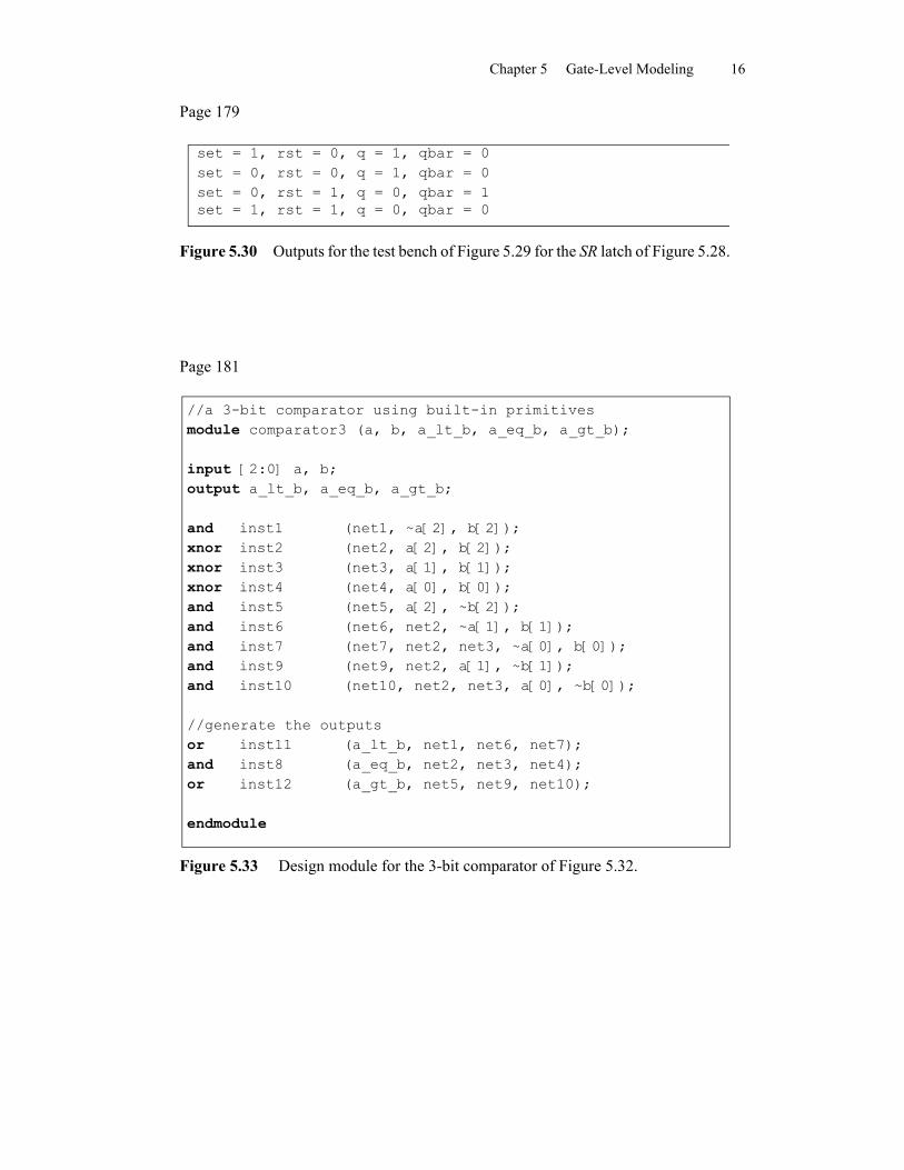
//a 3-bit comparator using built-in primitivesmodule comparator3 (a, b, a_lt_b, a_eq_b, a_gt_b);
input [2:0] a, b;output a_lt_b, a_eq_b, a_gt_b;
and inst1 (net1, ~a[2], b[2]);xnor inst2 (net2, a[2], b[2]);xnor inst3 (net3, a[1], b[1]);xnor inst4 (net4, a[0], b[0]);and inst5 (net5, a[2], ~b[2]);and inst6 (net6, net2, ~a[1], b[1]);and inst7 (net7, net2, net3, ~a[0], b[0]);and inst9 (net9, net2, a[1], ~b[1]);and inst10 (net10, net2, net3, a[0], ~b[0]);
//generate the outputsor inst11 (a_lt_b, net1, net6, net7);and inst8 (a_eq_b, net2, net3, net4);or inst12 (a_gt_b, net5, net9, net10);
endmodule
Figure 5.33 Design module for the 3-bit comparator of Figure 5.32.
Chapter 5 Gate-Level Modeling 17
Page 181
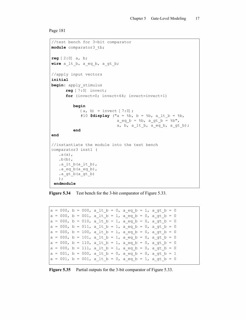
//test bench for 3-bit comparatormodule comparator3_tb;
reg [2:0] a, b;wire a_lt_b, a_eq_b, a_gt_b;
//apply input vectorsinitialbegin: apply_stimulus
reg [7:0] invect;for (invect=0; invect<64; invect=invect+1)
begin{a, b} = invect [7:0];#10 $display ("a = %b, b = %b, a_lt_b = %b,
a_eq_b = %b, a_gt_b = %b",a, b, a_lt_b, a_eq_b, a_gt_b);
endend
//instantiate the module into the test benchcomparator3 inst1 (
.a(a),
.b(b),
.a_lt_b(a_lt_b),
.a_eq_b(a_eq_b),
.a_gt_b(a_gt_b));
endmodule
Figure 5.34 Test bench for the 3-bit comparator of Figure 5.33.
a = 000, b = 000, a_lt_b = 0, a_eq_b = 1, a_gt_b = 0a = 000, b = 001, a_lt_b = 1, a_eq_b = 0, a_gt_b = 0a = 000, b = 010, a_lt_b = 1, a_eq_b = 0, a_gt_b = 0a = 000, b = 011, a_lt_b = 1, a_eq_b = 0, a_gt_b = 0a = 000, b = 100, a_lt_b = 1, a_eq_b = 0, a_gt_b = 0a = 000, b = 101, a_lt_b = 1, a_eq_b = 0, a_gt_b = 0a = 000, b = 110, a_lt_b = 1, a_eq_b = 0, a_gt_b = 0a = 000, b = 111, a_lt_b = 1, a_eq_b = 0, a_gt_b = 0a = 001, b = 000, a_lt_b = 0, a_eq_b = 0, a_gt_b = 1a = 001, b = 001, a_lt_b = 0, a_eq_b = 1, a_gt_b = 0
Figure 5.35 Partial outputs for the 3-bit comparator of Figure 5.33.
Chapter 5 Gate-Level Modeling 18
Page 186
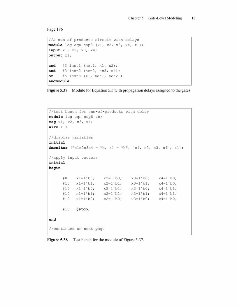
//a sum-of-products circuit with delaysmodule log_eqn_sop8 (x1, x2, x3, x4, z1);input x1, x2, x3, x4;output z1;
and #3 inst1 (net1, x1, x2);and #3 inst2 (net2, ~x3, x4);or #5 inst3 (z1, net1, net2);endmodule
Figure 5.37 Module for Equation 5.5 with propagation delays assigned to the gates.
//test bench for sum-of-products with delaymodule log_eqn_sop8_tb;reg x1, x2, x3, x4;wire z1;
//display variablesinitial$monitor ("x1x2x3x4 = %b, z1 = %b", {x1, x2, x3, x4}, z1);
//apply input vectorsinitialbegin
#0 x1=1'b0; x2=1'b0; x3=1'b0; x4=1'b0;#10 x1=1'b1; x2=1'b1; x3=1'b1; x4=1'b0;#10 x1=1'b0; x2=1'b1; x3=1'b0; x4=1'b1;#10 x1=1'b1; x2=1'b1; x3=1'b1; x4=1'b1;#10 x1=1'b0; x2=1'b0; x3=1'b0; x4=1'b0;
#10 $stop;
end
//continued on next page
Figure 5.38 Test bench for the module of Figure 5.37.
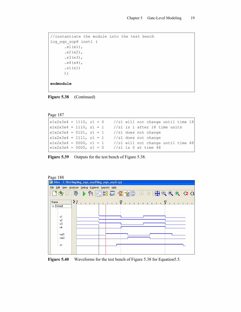
Chapter 5 Gate-Level Modeling 19
//instantiate the module into the test benchlog_eqn_sop8 inst1 (
.x1(x1),
.x2(x2),
.x3(x3),
.x4(x4),
.z1(z1));
endmodule
Figure 5.38 (Continued)
Page 187x1x2x3x4 = 1110, z1 = 0 //z1 will not change until time 18x1x2x3x4 = 1110, z1 = 1 //z1 is 1 after 18 time unitsx1x2x3x4 = 0101, z1 = 1 //z1 does not changex1x2x3x4 = 1111, z1 = 1 //z1 does not changex1x2x3x4 = 0000, z1 = 1 //z1 will not change until time 48x1x2x3x4 = 0000, z1 = 0 //z1 is 0 at time 48
Figure 5.39 Outputs for the test bench of Figure 5.38.
Page 188
Figure 5.40 Waveforms for the test bench of Figure 5.38 for Equation5.5.
Chapter 5 Gate-Level Modeling 20
Page 189
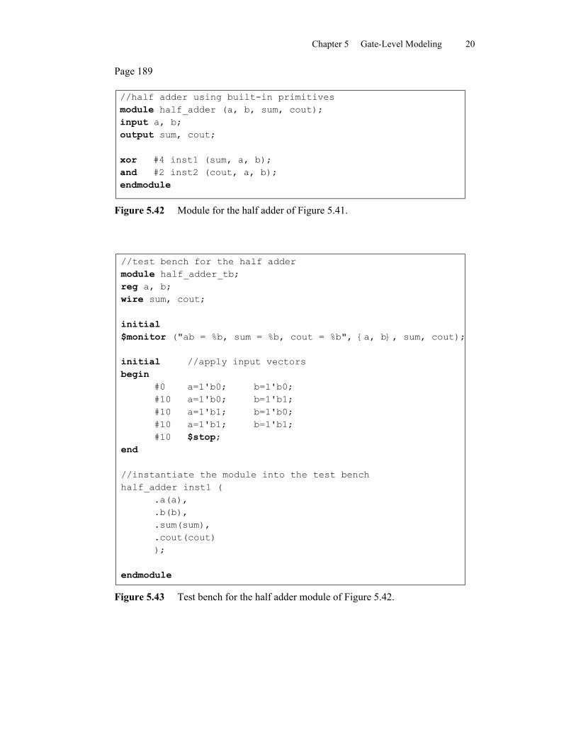
//half adder using built-in primitivesmodule half_adder (a, b, sum, cout);input a, b;output sum, cout;
xor #4 inst1 (sum, a, b);and #2 inst2 (cout, a, b);endmodule
Figure 5.42 Module for the half adder of Figure 5.41.
//test bench for the half addermodule half_adder_tb;reg a, b;wire sum, cout;
initial$monitor ("ab = %b, sum = %b, cout = %b", {a, b}, sum, cout);
initial //apply input vectorsbegin
#0 a=1'b0; b=1'b0;#10 a=1'b0; b=1'b1;#10 a=1'b1; b=1'b0;#10 a=1'b1; b=1'b1;#10 $stop;
end
//instantiate the module into the test benchhalf_adder inst1 (
.a(a),
.b(b),
.sum(sum),
.cout(cout));
endmodule
Figure 5.43 Test bench for the half adder module of Figure 5.42.
Chapter 5 Gate-Level Modeling 21
Page 190
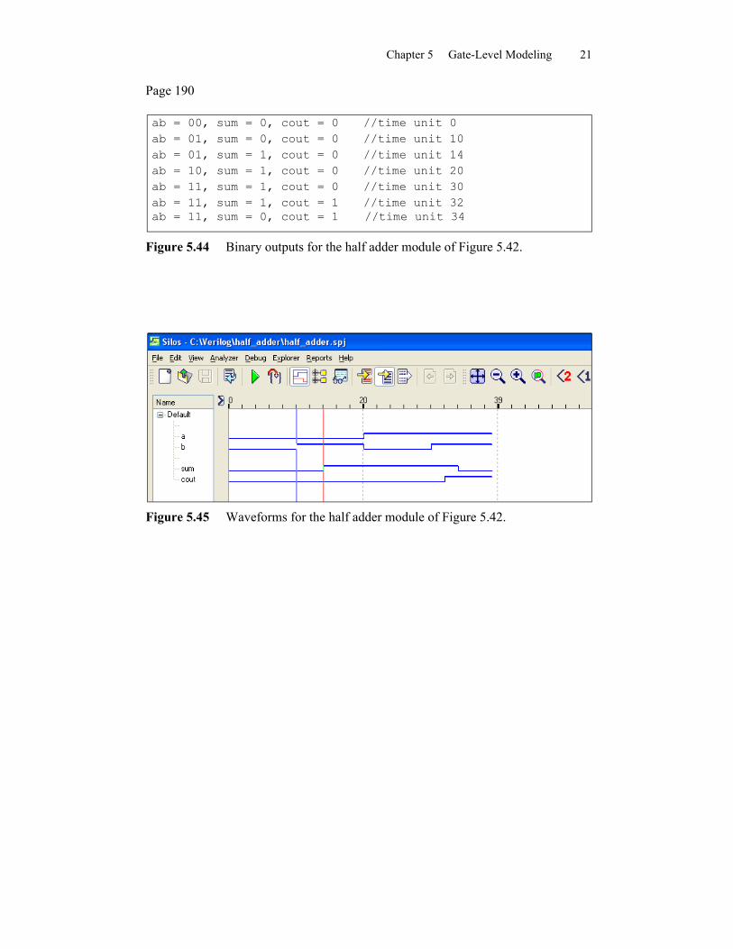
ab = 00, sum = 0, cout = 0 //time unit 0ab = 01, sum = 0, cout = 0 //time unit 10ab = 01, sum = 1, cout = 0 //time unit 14ab = 10, sum = 1, cout = 0 //time unit 20ab = 11, sum = 1, cout = 0 //time unit 30ab = 11, sum = 1, cout = 1 //time unit 32ab = 11, sum = 0, cout = 1 //time unit 34
Figure 5.44 Binary outputs for the half adder module of Figure 5.42.
Figure 5.45 Waveforms for the half adder module of Figure 5.42.
Chapter 5 Gate-Level Modeling 22
Page 193
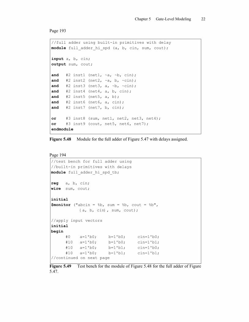
//full adder using built-in primitives with delaymodule full_adder_hi_spd (a, b, cin, sum, cout);
input a, b, cin;output sum, cout;
and #2 inst1 (net1, ~a, ~b, cin);and #2 inst2 (net2, ~a, b, ~cin);and #2 inst3 (net3, a, ~b, ~cin);and #2 inst4 (net4, a, b, cin);and #2 inst5 (net5, a, b);and #2 inst6 (net6, a, cin);and #2 inst7 (net7, b, cin);
or #3 inst8 (sum, net1, net2, net3, net4);or #3 inst9 (cout, net5, net6, net7);endmodule
Figure 5.48 Module for the full adder of Figure 5.47 with delays assigned.
Page 194//test bench for full adder using//built-in primitives with delaysmodule full_adder_hi_spd_tb;
reg a, b, cin;wire sum, cout;
initial$monitor ("abcin = %b, sum = %b, cout = %b",
{a, b, cin}, sum, cout);
//apply input vectorsinitialbegin
#0 a=1'b0; b=1'b0; cin=1'b0;#10 a=1'b0; b=1'b0; cin=1'b1;#10 a=1'b0; b=1'b1; cin=1'b0;#10 a=1'b0; b=1'b1; cin=1'b1;
//continued on next page
Figure 5.49 Test bench for the module of Figure 5.48 for the full adder of Figure5.47.
Chapter 5 Gate-Level Modeling 23
#10 a=1'b1; b=1'b0; cin=1'b0;#10 a=1'b1; b=1'b0; cin=1'b1;#10 a=1'b1; b=1'b1; cin=1'b0;#10 a=1'b1; b=1'b1; cin=1'b1;#10 $stop;
end
//instantiate the module into the test benchfull_adder_hi_spd inst1 (
.a(a),
.b(b),
.cin(cin),
.sum(sum),
.cout(cout));
endmodule
Figure 5.49 (Continued)
Page 195
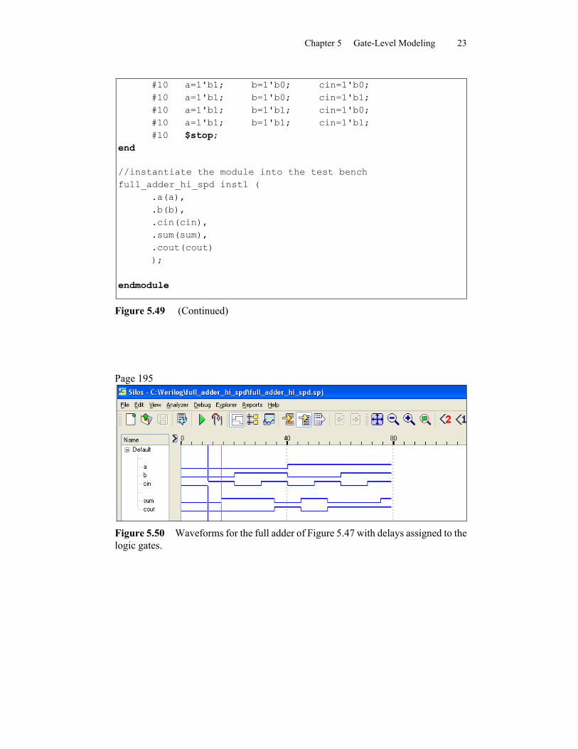
Figure 5.50 Waveforms for the full adder of Figure 5.47 with delays assigned to the logic gates.
Chapter 5 Gate-Level Modeling 24
Page 196
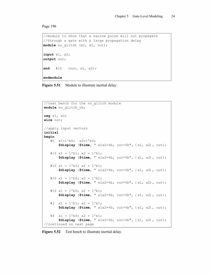
//module to show that a narrow pulse will not propagate//through a gate with a large propagation delaymodule no_glitch (x1, x2, out);
input x1, x2;output out;
and #10 (out, x1, x2);
endmodule
Figure 5.51 Module to illustrate inertial delay.
//test bench for the no_glitch modulemodule no_glitch_tb;
reg x1, x2;wire out;
//apply input vectorsinitialbegin
#0 x1=1'b0; x2=1'b0; $display ($time, " x1x2=%b, out=%b", {x1, x2}, out);
#10 x1 = 1'b1; x2 = 1'b1; $display ($time, " x1x2=%b, out=%b", {x1, x2}, out);
#10 x1 = 1'b1; x2 = 1'b1; $display ($time, " x1x2=%b, out=%b", {x1, x2}, out);
#10 x1 = 1'b0; x2 = 1'b1; $display ($time, " x1x2=%b, out=%b", {x1, x2}, out);
#10 x1 = 1'b0; x2 = 1'b1; $display ($time, " x1x2=%b, out=%b", {x1, x2}, out);
#3 x1 = 1'b1; x2 = 1'b1; $display ($time, " x1x2=%b, out=%b", {x1, x2}, out);
#4 x1 = 1'b0; x2 = 1'b1; $display ($time, " x1x2=%b, out=%b", {x1, x2}, out);
//continued on next page
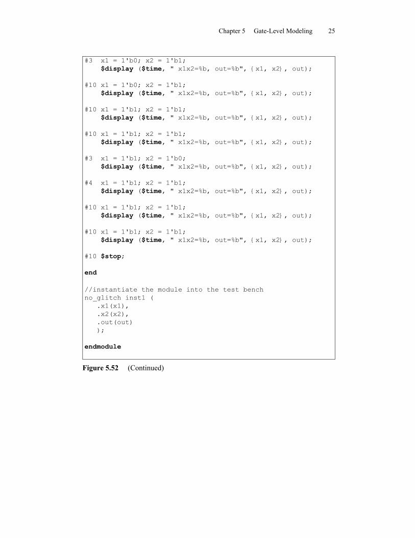
Figure 5.52 Test bench to illustrate inertial delay.
Chapter 5 Gate-Level Modeling 25
#3 x1 = 1'b0; x2 = 1'b1; $display ($time, " x1x2=%b, out=%b", {x1, x2}, out);
#10 x1 = 1'b0; x2 = 1'b1; $display ($time, " x1x2=%b, out=%b", {x1, x2}, out);
#10 x1 = 1'b1; x2 = 1'b1; $display ($time, " x1x2=%b, out=%b", {x1, x2}, out);
#10 x1 = 1'b1; x2 = 1'b1; $display ($time, " x1x2=%b, out=%b", {x1, x2}, out);
#3 x1 = 1'b1; x2 = 1'b0; $display ($time, " x1x2=%b, out=%b", {x1, x2}, out);
#4 x1 = 1'b1; x2 = 1'b1; $display ($time, " x1x2=%b, out=%b", {x1, x2}, out);
#10 x1 = 1'b1; x2 = 1'b1; $display ($time, " x1x2=%b, out=%b", {x1, x2}, out);
#10 x1 = 1'b1; x2 = 1'b1; $display ($time, " x1x2=%b, out=%b", {x1, x2}, out);
#10 $stop;
end
//instantiate the module into the test benchno_glitch inst1 (
.x1(x1),
.x2(x2),
.out(out));
endmodule
Figure 5.52 (Continued)
Chapter 5 Gate-Level Modeling 26
Page 198
0 x1x2=00, out=010 x1x2=11, out=020 x1x2=11, out=130 x1x2=01, out=140 x1x2=01, out=043 x1x2=11, out=047 x1x2=01, out=050 x1x2=01, out=060 x1x2=01, out=070 x1x2=11, out=080 x1x2=11, out=183 x1x2=10, out=187 x1x2=11, out=197 x1x2=11, out=1107 x1x2=11, out=1
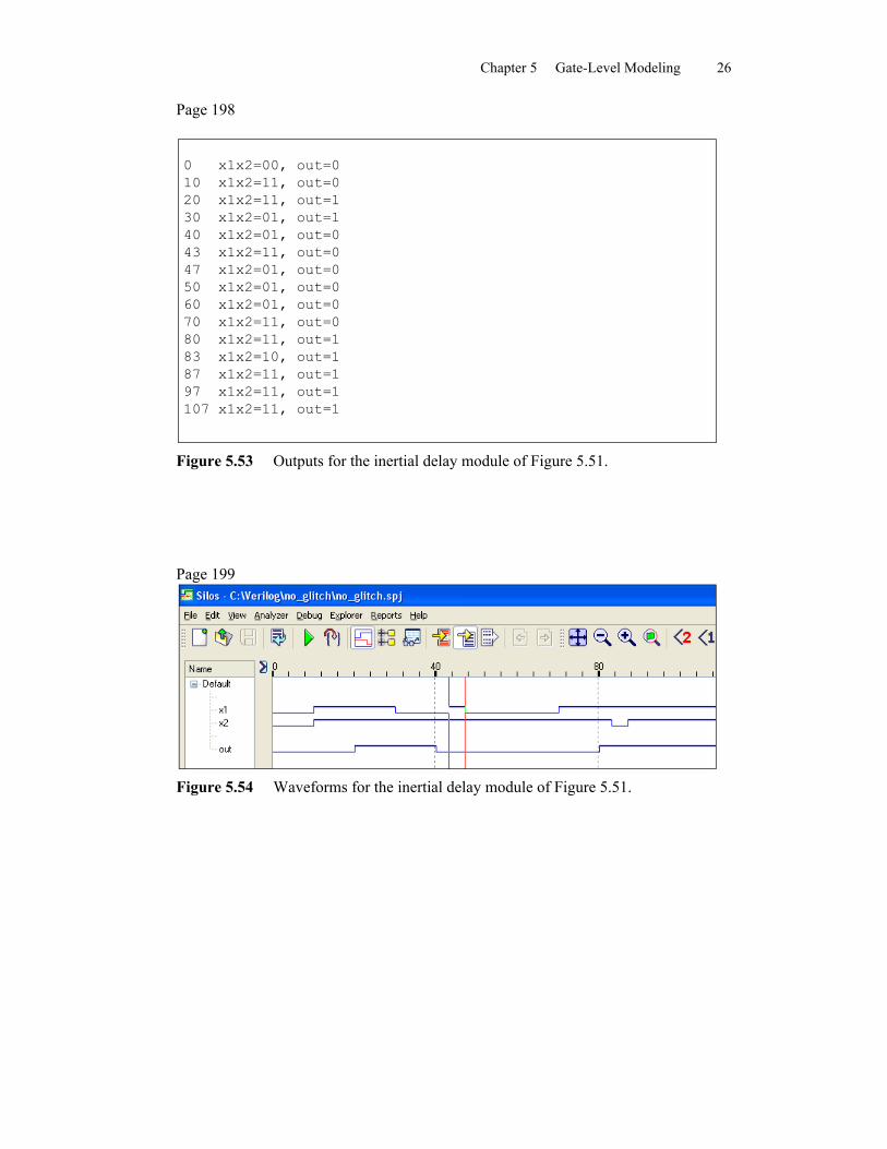
Figure 5.53 Outputs for the inertial delay module of Figure 5.51.
Page 199
Figure 5.54 Waveforms for the inertial delay module of Figure 5.51.
Chapter 5 Gate-Level Modeling 27
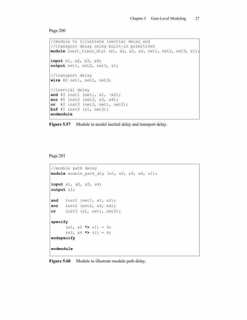
Page 200
//module to illustrate inertial delay and//transport delay using built-in primitivesmodule inert_trans_dly1 (x1, x2, x3, x4, net1, net2, net3, z1);
input x1, x2, x3, x4;output net1, net2, net3, z1;
//transport delaywire #2 net1, net2, net3;
//inertial delayand #3 inst1 (net1, x1, ~x2);xor #5 inst2 (net2, x3, x4);or #2 inst3 (net3, net1, net2);buf #1 inst4 (z1, net3);endmodule
Figure 5.57 Module to model inertial delay and transport delay.
Page 201
//module path delaymodule module_path_dly (x1, x2, x3, x4, z1);
input x1, x2, x3, x4;output z1;
and inst1 (net1, x1, x2);xor inst2 (net2, x3, x4);or inst3 (z1, net1, net2);
specify(x1, x2 *> z1) = 6;(x3, x4 *> z1) = 8;
endspecify
endmodule
Figure 5.60 Module to illustrate module path delay.
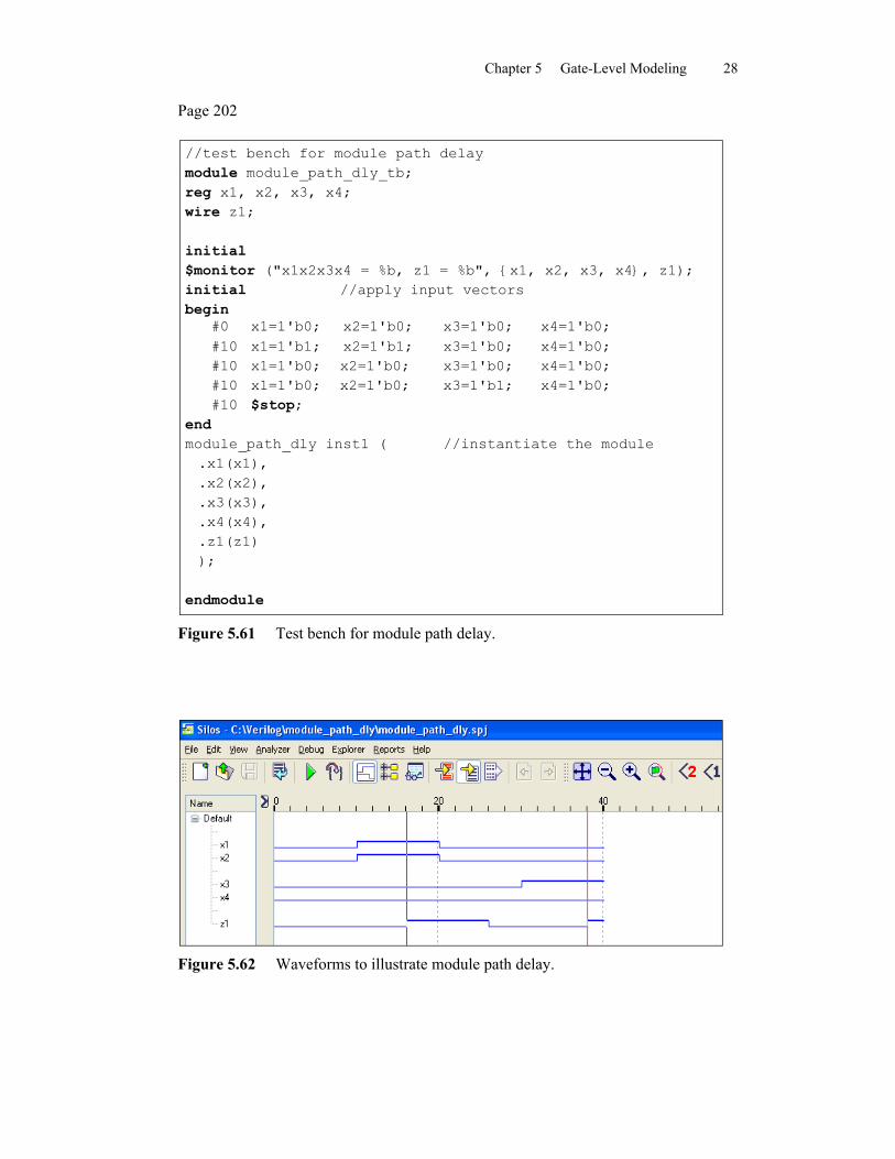
Chapter 5 Gate-Level Modeling 28
Page 202
//test bench for module path delaymodule module_path_dly_tb;reg x1, x2, x3, x4;wire z1;
initial$monitor ("x1x2x3x4 = %b, z1 = %b", {x1, x2, x3, x4}, z1);initial //apply input vectorsbegin
#0 x1=1'b0; x2=1'b0; x3=1'b0; x4=1'b0;#10 x1=1'b1; x2=1'b1; x3=1'b0; x4=1'b0;#10 x1=1'b0; x2=1'b0; x3=1'b0; x4=1'b0;#10 x1=1'b0; x2=1'b0; x3=1'b1; x4=1'b0;#10 $stop;
endmodule_path_dly inst1 ( //instantiate the module.x1(x1),.x2(x2),.x3(x3),.x4(x4),.z1(z1));
endmodule
Figure 5.61 Test bench for module path delay.
Figure 5.62 Waveforms to illustrate module path delay.
Chapter 5 Gate-Level Modeling 29
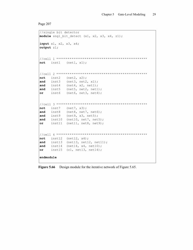
Page 207
//single bit detectormodule sngl_bit_detect (x1, x2, x3, x4, z1);
input x1, x2, x3, x4;output z1;
//cell 1 ************************************************not inst1 (net1, x1);
//cell 2 ************************************************not inst2 (net2, x2);and inst3 (net3, net2, x1);and inst4 (net4, x2, net1);and inst5 (net5, net2, net1);or inst6 (net6, net3, net4);
//cell 3 ************************************************not inst7 (net7, x3);and inst8 (net8, net7, net6);and inst9 (net9, x3, net5);and inst10 (net10, net7, net5);or inst11 (net11, net8, net9);
//cell 4 ************************************************not inst12 (net12, x4);and inst13 (net13, net12, net11);and inst14 (net14, x4, net10);or inst15 (z1, net13, net14);
endmodule
Figure 5.66 Design module for the iterative network of Figure 5.65.
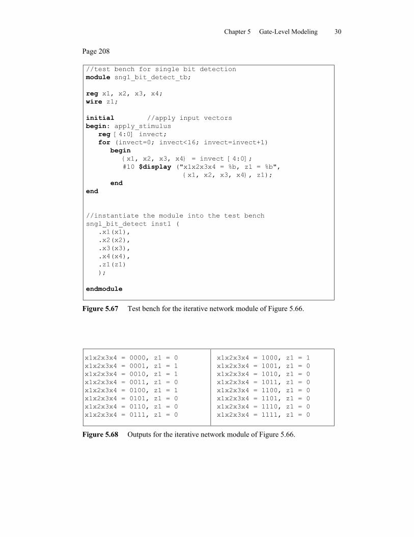
Chapter 5 Gate-Level Modeling 30
Page 208
//test bench for single bit detectionmodule sngl_bit_detect_tb;
reg x1, x2, x3, x4;wire z1;
initial //apply input vectorsbegin: apply_stimulus
reg [4:0] invect;for (invect=0; invect<16; invect=invect+1)
begin{x1, x2, x3, x4} = invect [4:0];#10 $display ("x1x2x3x4 = %b, z1 = %b",
{x1, x2, x3, x4}, z1);end
end
//instantiate the module into the test benchsngl_bit_detect inst1 (
.x1(x1),
.x2(x2),
.x3(x3),
.x4(x4),
.z1(z1));
endmodule
Figure 5.67 Test bench for the iterative network module of Figure 5.66.
x1x2x3x4 = 0000, z1 = 0x1x2x3x4 = 0001, z1 = 1x1x2x3x4 = 0010, z1 = 1x1x2x3x4 = 0011, z1 = 0x1x2x3x4 = 0100, z1 = 1x1x2x3x4 = 0101, z1 = 0x1x2x3x4 = 0110, z1 = 0x1x2x3x4 = 0111, z1 = 0
x1x2x3x4 = 1000, z1 = 1x1x2x3x4 = 1001, z1 = 0x1x2x3x4 = 1010, z1 = 0x1x2x3x4 = 1011, z1 = 0x1x2x3x4 = 1100, z1 = 0x1x2x3x4 = 1101, z1 = 0x1x2x3x4 = 1110, z1 = 0x1x2x3x4 = 1111, z1 = 0
Figure 5.68 Outputs for the iterative network module of Figure 5.66.
Chapter 5 Gate-Level Modeling 31
Page 209
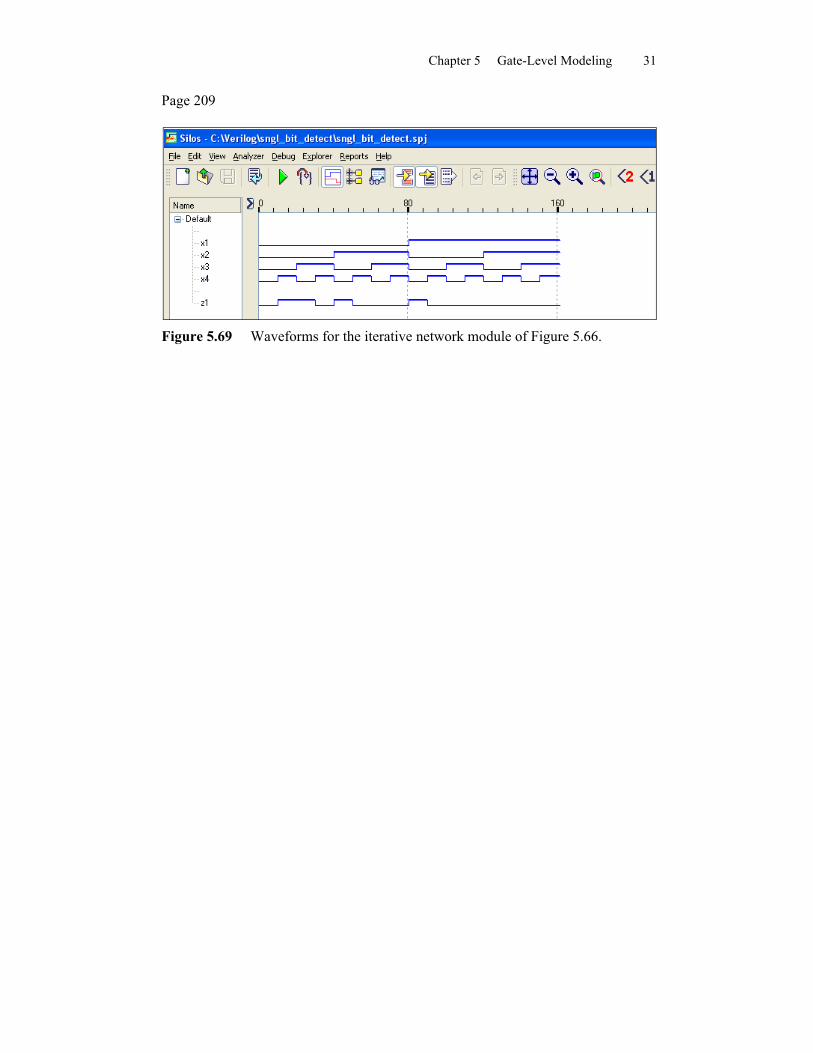
Figure 5.69 Waveforms for the iterative network module of Figure 5.66.
Chapter 5 Gate-Level Modeling 32
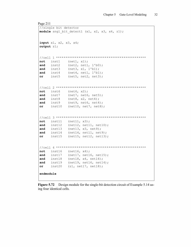
Page 211//single bit detectormodule sngl_bit_detect1 (x1, x2, x3, x4, z1);
input x1, x2, x3, x4;output z1;
//cell 1 ************************************************not inst1 (net1, x1);and inst2 (net2, net1, 1'b0);and inst3 (net3, x1, 1'b1);and inst4 (net4, net1, 1'b1);or inst5 (net5, net2, net3);
//cell 2 ************************************************not inst6 (net6, x2);and inst7 (net7, net6, net5);and inst8 (net8, x2, net4);and inst9 (net9, net6, net4);or inst10 (net10, net7, net8);
//cell 3 ************************************************not inst11 (net11, x3);and inst12 (net12, net11, net10);and inst13 (net13, x3, net9);and inst14 (net14, net11, net9);or inst15 (net15, net12, net13);
//cell 4 ************************************************not inst16 (net16, x4);and inst17 (net17, net16, net15);and inst18 (net18, x4, net14);and inst19 (net19, net16, net14);or inst20 (z1, net17, net18);
endmodule
Figure 5.72 Design module for the single-bit detection circuit of Example 5.14 us-ing four identical cells.
Chapter 5 Gate-Level Modeling 33
Page 212
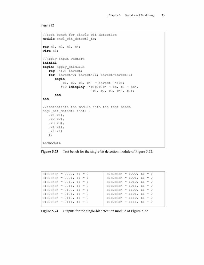
//test bench for single bit detectionmodule sngl_bit_detect1_tb;
reg x1, x2, x3, x4;wire z1;
//apply input vectorsinitialbegin: apply_stimulus
reg [4:0] invect;for (invect=0; invect<16; invect=invect+1)
begin{x1, x2, x3, x4} = invect [4:0];#10 $display ("x1x2x3x4 = %b, z1 = %b",
{x1, x2, x3, x4}, z1);end
end
//instantiate the module into the test benchsngl_bit_detect1 inst1 (
.x1(x1),
.x2(x2),
.x3(x3),
.x4(x4),
.z1(z1));
endmodule
Figure 5.73 Test bench for the single-bit detection module of Figure 5.72.
x1x2x3x4 = 0000, z1 = 0x1x2x3x4 = 0001, z1 = 1x1x2x3x4 = 0010, z1 = 1x1x2x3x4 = 0011, z1 = 0x1x2x3x4 = 0100, z1 = 1x1x2x3x4 = 0101, z1 = 0x1x2x3x4 = 0110, z1 = 0x1x2x3x4 = 0111, z1 = 0
x1x2x3x4 = 1000, z1 = 1x1x2x3x4 = 1001, z1 = 0x1x2x3x4 = 1010, z1 = 0x1x2x3x4 = 1011, z1 = 0x1x2x3x4 = 1100, z1 = 0x1x2x3x4 = 1101, z1 = 0x1x2x3x4 = 1110, z1 = 0x1x2x3x4 = 1111, z1 = 0
Figure 5.74 Outputs for the single-bit detection module of Figure 5.72.
Chapter 5 Gate-Level Modeling 34
Page 213
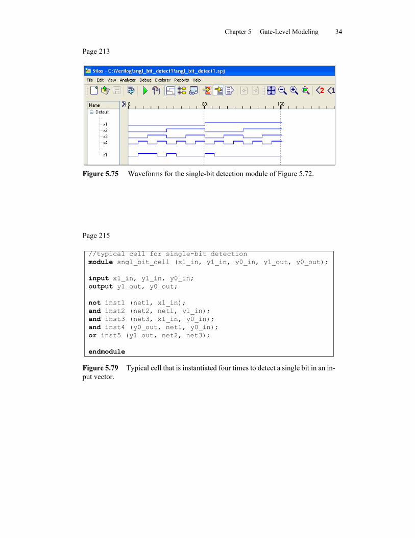
Figure 5.75 Waveforms for the single-bit detection module of Figure 5.72.
Page 215
//typical cell for single-bit detection module sngl_bit_cell (x1_in, y1_in, y0_in, y1_out, y0_out);
input x1_in, y1_in, y0_in; output y1_out, y0_out;
not inst1 (net1, x1_in); and inst2 (net2, net1, y1_in); and inst3 (net3, x1_in, y0_in); and inst4 (y0_out, net1, y0_in); or inst5 (y1_out, net2, net3);
endmodule
Figure 5.79 Typical cell that is instantiated four times to detect a single bit in an in-put vector.
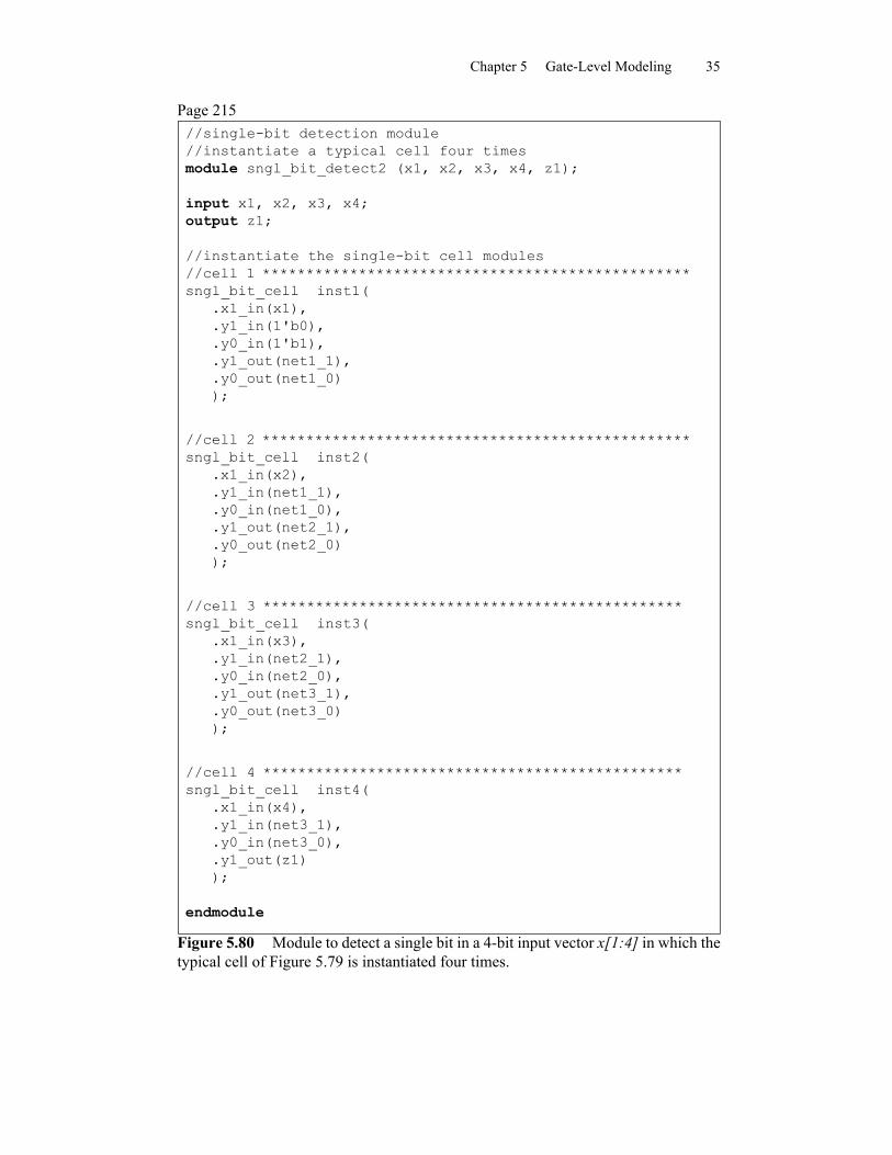
Chapter 5 Gate-Level Modeling 35
Page 215//single-bit detection module//instantiate a typical cell four times module sngl_bit_detect2 (x1, x2, x3, x4, z1);
input x1, x2, x3, x4;output z1;
//instantiate the single-bit cell modules//cell 1 *************************************************sngl_bit_cell inst1(
.x1_in(x1),
.y1_in(1'b0),
.y0_in(1'b1),
.y1_out(net1_1),
.y0_out(net1_0));
//cell 2 *************************************************sngl_bit_cell inst2(
.x1_in(x2),
.y1_in(net1_1),
.y0_in(net1_0),
.y1_out(net2_1),
.y0_out(net2_0));
//cell 3 ************************************************sngl_bit_cell inst3(
.x1_in(x3),
.y1_in(net2_1),
.y0_in(net2_0),
.y1_out(net3_1),
.y0_out(net3_0));
//cell 4 ************************************************sngl_bit_cell inst4(
.x1_in(x4),
.y1_in(net3_1),
.y0_in(net3_0),
.y1_out(z1));
endmodule
Figure 5.80 Module to detect a single bit in a 4-bit input vector x[1:4] in which the typical cell of Figure 5.79 is instantiated four times.
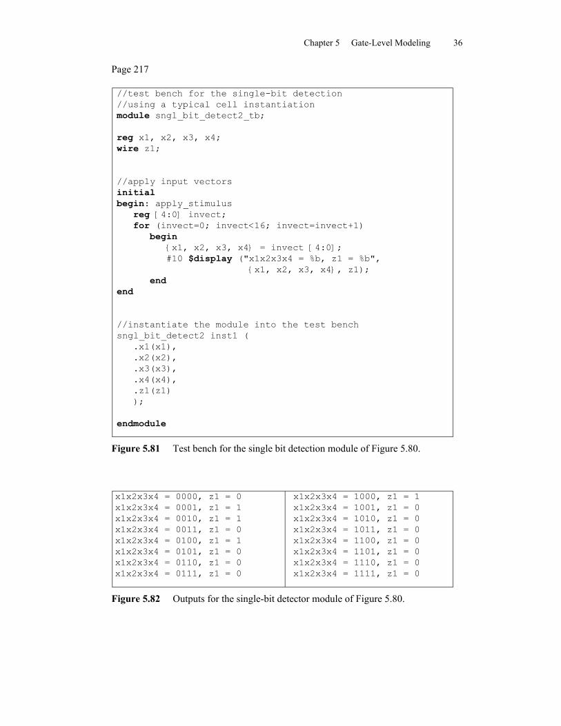
Chapter 5 Gate-Level Modeling 36
Page 217
//test bench for the single-bit detection//using a typical cell instantiationmodule sngl_bit_detect2_tb;
reg x1, x2, x3, x4;wire z1;
//apply input vectorsinitialbegin: apply_stimulus
reg [4:0] invect;for (invect=0; invect<16; invect=invect+1)
begin{x1, x2, x3, x4} = invect [4:0];#10 $display ("x1x2x3x4 = %b, z1 = %b",
{x1, x2, x3, x4}, z1);end
end
//instantiate the module into the test benchsngl_bit_detect2 inst1 (
.x1(x1),
.x2(x2),
.x3(x3),
.x4(x4),
.z1(z1));
endmodule
Figure 5.81 Test bench for the single bit detection module of Figure 5.80.
x1x2x3x4 = 0000, z1 = 0x1x2x3x4 = 0001, z1 = 1x1x2x3x4 = 0010, z1 = 1x1x2x3x4 = 0011, z1 = 0x1x2x3x4 = 0100, z1 = 1x1x2x3x4 = 0101, z1 = 0x1x2x3x4 = 0110, z1 = 0x1x2x3x4 = 0111, z1 = 0
x1x2x3x4 = 1000, z1 = 1x1x2x3x4 = 1001, z1 = 0x1x2x3x4 = 1010, z1 = 0x1x2x3x4 = 1011, z1 = 0x1x2x3x4 = 1100, z1 = 0x1x2x3x4 = 1101, z1 = 0x1x2x3x4 = 1110, z1 = 0x1x2x3x4 = 1111, z1 = 0
Figure 5.82 Outputs for the single-bit detector module of Figure 5.80.
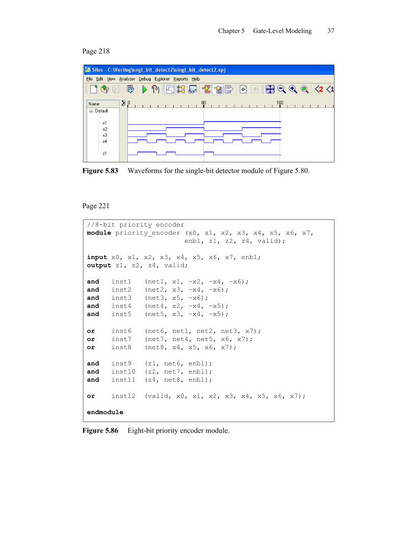
Chapter 5 Gate-Level Modeling 37
Page 218
Figure 5.83 Waveforms for the single-bit detector module of Figure 5.80.
Page 221
//8-bit priority encodermodule priority_encoder (x0, x1, x2, x3, x4, x5, x6, x7,
enbl, z1, z2, z4, valid);
input x0, x1, x2, x3, x4, x5, x6, x7, enbl;output z1, z2, z4, valid;
and inst1 (net1, x1, ~x2, ~x4, ~x6);and inst2 (net2, x3, ~x4, ~x6);and inst3 (net3, x5, ~x6);and inst4 (net4, x2, ~x4, ~x5);and inst5 (net5, x3, ~x4, ~x5);
or inst6 (net6, net1, net2, net3, x7);or inst7 (net7, net4, net5, x6, x7);or inst8 (net8, x4, x5, x6, x7);
and inst9 (z1, net6, enbl);and inst10 (z2, net7, enbl);and inst11 (z4, net8, enbl);
or inst12 (valid, x0, x1, x2, x3, x4, x5, x6, x7);
endmodule
Figure 5.86 Eight-bit priority encoder module.
Chapter 5 Gate-Level Modeling 38
Page 221
//test bench for 8-bit priority encodermodule priority_encoder_tb;reg x0, x1, x2, x3, x4, x5, x6, x7, enbl;wire z1, z2, z4, valid;
initial //display variables$monitor ("x0x1x2x3x4x5x6x7 = %b, z4z2z1 = %b, valid = %b",
{x0, x1, x2, x3, x4, x5, x6, x7}, {z4, z2, z1}, valid);initial //apply input vectorsbegin
#0 x0=1'b0; x1=1'b0; x2=1'b0; x3=1'b0;x4=1'b0; x5=1'b0; x6=1'b0; x7=1'b0; enbl=1'b1;
#10 x0=1'b0; x1=1'b0; x2=1'b1; x3=1'b0;x4=1'b0; x5=1'b0; x6=1'b0; x7=1'b0; enbl=1'b1;
#10 x0=1'b0; x1=1'b0; x2=1'b0; x3=1'b0;x4=1'b0; x5=1'b1; x6=1'b0; x7=1'b0; enbl=1'b1;
#10 x0=1'b0; x1=1'b0; x2=1'b1; x3=1'b0;x4=1'b0; x5=1'b0; x6=1'b1; x7=1'b0; enbl=1'b1;
#10 x0=1'b1; x1=1'b0; x2=1'b1; x3=1'b1;x4=1'b0; x5=1'b0; x6=1'b0; x7=1'b0; enbl=1'b1;
#10 x0=1'b1; x1=1'b1; x2=1'b1; x3=1'b1;x4=1'b1; x5=1'b1; x6=1'b1; x7=1'b1; enbl=1'b1;
#10 $stop;end
priority_encoder inst1 ( //instantiate the module.x0(x0),.x1(x1),.x2(x2),.x3(x3),.x4(x4),.x5(x5),.x6(x6),.x7(x7),.enbl(enbl),.z1(z1),.z2(z2),.z4(z4),.valid(valid));
endmodule
Figure 5.87 Test bench for the 8-bit priority encoder module of Figure 5.86.
Chapter 5 Gate-Level Modeling 39
Page 223
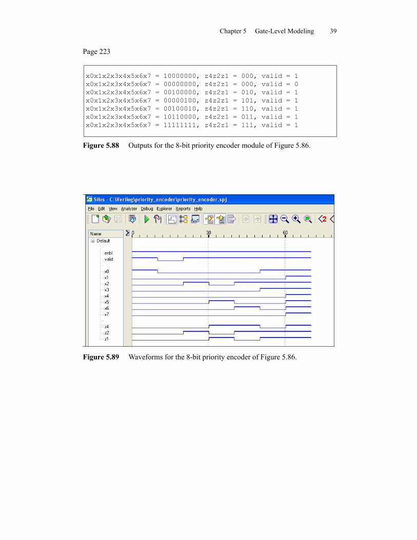
x0x1x2x3x4x5x6x7 = 10000000, z4z2z1 = 000, valid = 1x0x1x2x3x4x5x6x7 = 00000000, z4z2z1 = 000, valid = 0x0x1x2x3x4x5x6x7 = 00100000, z4z2z1 = 010, valid = 1x0x1x2x3x4x5x6x7 = 00000100, z4z2z1 = 101, valid = 1x0x1x2x3x4x5x6x7 = 00100010, z4z2z1 = 110, valid = 1x0x1x2x3x4x5x6x7 = 10110000, z4z2z1 = 011, valid = 1x0x1x2x3x4x5x6x7 = 11111111, z4z2z1 = 111, valid = 1
Figure 5.88 Outputs for the 8-bit priority encoder module of Figure 5.86.
Figure 5.89 Waveforms for the 8-bit priority encoder of Figure 5.86.