Embed Size (px)
Citation preview
FANS-1/A Operations Manual
Version 6.0
Effective 25 September 2008

Intentionally left blank.
FANS-1/A Operations Manual 25 September 2008
Table of Contents
1 INTRODUCTION............................................................................................... 1-1
1.1 Arrangement of the FOM .................................................................................................................... 1-1
1.2 Document Management........................................................................................................................ 1-1
1.3 Copies..................................................................................................................................................... 1-2
1.4 Changes to the FOM............................................................................................................................. 1-3
1.5 Editing conventions............................................................................................................................... 1-3
1.6 Request For Change Form................................................................................................................... 1-4
1.7 Amendment Record .............................................................................................................................. 1-5
2 ACRONYM LIST............................................................................................... 2-1
3 SYSTEM INTEGRITY AND MONITORING ...................................................... 3-1
3.1 Introduction........................................................................................................................................... 3-1
3.2 Personnel Licensing and Training....................................................................................................... 3-1
3.3 Reference Documents ........................................................................................................................... 3-1
3.4 System Performance Criteria .............................................................................................................. 3-2
3.5 ATC System Validation........................................................................................................................ 3-3 3.5.1 System safety assessment................................................................................................................ 3-3 3.5.2 Integration test ................................................................................................................................ 3-3 3.5.3 ATS operation manuals................................................................................................................... 3-3 3.5.4 ATS System Integrity...................................................................................................................... 3-3
3.6 System Monitoring................................................................................................................................ 3-3 3.6.1 The monitoring process................................................................................................................... 3-4 3.6.2 Dispatch of confidential information .............................................................................................. 3-4 3.6.3 FANS-1/A problem reports............................................................................................................. 3-4 3.6.4 FANS-1/A periodic status report .................................................................................................... 3-4 3.6.5 Processing of reports....................................................................................................................... 3-4
3.7 FANS Interoperability Team ............................................................................................................... 3-5
3.8 Central Reporting Agency ................................................................................................................... 3-5
3.9 Local Data Recording and Analysis .................................................................................................... 3-5 3.9.1 Data recording................................................................................................................................. 3-5 3.9.2 Local data collection ....................................................................................................................... 3-6
3.10 Reporting FANS Problems ................................................................................................................. 3-7 3.10.1 FANS-1/A Problem Report............................................................................................................. 3-8 3.10.2 Description of fields........................................................................................................................ 3-9
3.11 FANS-1/A Periodic Status Report Form .......................................................................................... 3-10
Page i Version 6.0
25 September 2008 FANS-1/A Operations Manual
4 CONNECTION MANAGEMENT .......................................................................4-1
4.1 Pre-Flight Phase .................................................................................................................................... 4-1 4.1.1 Identifying data link aircraft equipage ............................................................................................ 4-1 4.1.2 Registration number ........................................................................................................................ 4-1
4.2 The CPDLC Connection Sequence...................................................................................................... 4-2
4.3 The AFN Logon ..................................................................................................................................... 4-2 4.3.1 Prerequisite for CPDLC and / or ADS-C connection...................................................................... 4-2 4.3.2 Initiating an AFN logon .................................................................................................................. 4-2 4.3.3 Purpose of an AFN logon................................................................................................................ 4-2 4.3.4 The initial AFN logon ..................................................................................................................... 4-3
4.3.4.1 Timing of the initial AFN logon ................................................................................................ 4-3 4.3.4.2 Notification of ATS variations .................................................................................................... 4-3 4.3.4.3 Constructing the FN_CON message ........................................................................................... 4-3 4.3.4.4 FMS and ACARS flight identification ........................................................................................ 4-3
4.4 CPDLC Connection .............................................................................................................................. 4-4 4.4.1 Purpose CPDLC connection............................................................................................................ 4-4 4.4.2 Management Of CPDLC connections ............................................................................................. 4-4 4.4.3 CPDLC connection sequence.......................................................................................................... 4-4 4.4.4 Active and inactive CPDLC connections ........................................................................................ 4-4
4.4.4.1 Determination of an active CPDLC connection .......................................................................... 4-4
4.5 Next Data Authority Notification ........................................................................................................ 4-6 4.5.1 Purpose of the NDA message.......................................................................................................... 4-6 4.5.2 Procedure for the NDA notification ................................................................................................ 4-6
4.5.2.1 Sequence of the NDA and FN_CAD messages .......................................................................... 4-6 4.5.2.2 Change of the NDA..................................................................................................................... 4-6
4.5.3 Abnormal cases relating to the NDA notification ........................................................................... 4-7 4.5.3.1 Unsuccessful NDA delivery........................................................................................................ 4-7 4.5.3.2 Duplication of the NDA message................................................................................................ 4-7
4.6 AFN Logon Triggered By Address Forwarding................................................................................. 4-7 4.6.1 Purpose and procedure .................................................................................................................... 4-7 4.6.2 An aircraft transferring from one data link area to another............................................................. 4-7 4.6.3 Aircraft transiting data link areas .................................................................................................... 4-8
4.6.3.1 Options for initiating the AFN logon .......................................................................................... 4-8 4.6.3.2 Transferring CPDLC for short transits ........................................................................................ 4-9
4.7 End of Service and CPDLC Connection Transfer ............................................................................. 4-9 4.7.1 Purpose and procedure .................................................................................................................... 4-9
4.7.1.1 Uplink messages to be closed before the END SERVICE .............................................................. 4-9 4.7.1.2 Use of Contact/Monitor Uplink Message.................................................................................... 4-9 4.7.1.3 Synchronizing the CPDLC and voice transfer .......................................................................... 4-10 4.7.1.4 Timing of the transfer of communications ................................................................................ 4-10 4.7.1.5 Aircraft entering VHF coverage................................................................................................ 4-10 4.7.1.6 Timing of the CPDLC connection............................................................................................. 4-10
4.7.2 Abnormal cases at the time of the connection / disconnection...................................................... 4-11 4.7.2.1 Non-delivery of END SERVICE message .................................................................................... 4-11 4.7.2.2 Non-automatic termination of the connection ........................................................................... 4-11
5 CPDLC PROCEDURES....................................................................................5-1
5.1 Means of Communication..................................................................................................................... 5-1 5.1.1 General ............................................................................................................................................ 5-1 5.1.2 Voice communications .................................................................................................................... 5-1
Version 6.0 Page ii
FANS-1/A Operations Manual 25 September 2008
5.1.2.1 Notification of frequencies to the preceding ATSU.................................................................... 5-1 5.1.2.2 Notification of HF frequencies by CPDLC................................................................................. 5-1
5.2 CPDLC Capability................................................................................................................................ 5-1 5.2.1 Notification of CPDLC capability .................................................................................................. 5-1 5.2.2 Downlink messages......................................................................................................................... 5-1 5.2.3 Uplink messages ............................................................................................................................. 5-2
5.3 Use of Pre-Formatted and Free Text Messages.................................................................................. 5-2 5.3.1 Preferred use of pre-formatted messages ........................................................................................ 5-2 5.3.2 Standardized free text messages...................................................................................................... 5-2 5.3.3 Storing free text messages............................................................................................................... 5-2
5.4 Exchange of CPDLC messages ............................................................................................................ 5-2 5.4.1 Message assurance .......................................................................................................................... 5-2 5.4.2 Ambiguous dialogues...................................................................................................................... 5-2 5.4.3 Interruption of a CPDLC dialogue.................................................................................................. 5-2 5.4.4 Approval of request or clearance / instruction ................................................................................ 5-3
5.4.4.1 Affirmative response to a clearance/instruction.......................................................................... 5-3 5.4.4.2 Affirmative response to a clearance request ............................................................................... 5-3 5.4.4.3 Conditions relating to a specific clearance.................................................................................. 5-3 5.4.4.4 Affirmative response to a negotiation request............................................................................. 5-3
5.4.5 Negative response to a downlink request........................................................................................ 5-3 5.4.5.1 Negative response to a clearance request.................................................................................... 5-3 5.4.5.2 Explanation of negative response ............................................................................................... 5-3 5.4.5.3 Offering alternative clearances to downlink requests ................................................................. 5-3
5.4.6 Negative response to an uplink request........................................................................................... 5-3 5.4.7 Time period between receiving and responding to a message ........................................................ 5-3
5.4.7.1 Delays in responding................................................................................................................... 5-4 5.4.7.2 Delay expected after receiving a “STANDBY” message ........................................................... 5-4
5.4.8 Re-sending Messages...................................................................................................................... 5-4 5.4.8.1 Re-sending of a message when no alert received........................................................................ 5-4 5.4.8.2 Re-sending of a message when an alert has been received ......................................................... 5-4
5.4.9 Duplicate requests received ............................................................................................................ 5-4 5.4.9.1 Second identical request after an uplink “STANDBY” message................................................ 5-4 5.4.9.2 Multiple identical requests .......................................................................................................... 5-4
5.4.10 Altitude change clearances.............................................................................................................. 5-5 5.4.10.1 Issuing conditional altitude change clearances ....................................................................... 5-5 5.4.10.2 Level report requirements for climb or descent clearances..................................................... 5-5 5.4.10.3 Canceling block altitude clearances ........................................................................................ 5-5 5.4.10.4 Issuing Level Restrictions ....................................................................................................... 5-5
5.4.11 Requesting an aircraft’s speed ........................................................................................................ 5-6 5.4.12 Advising a wake turbulence offset.................................................................................................. 5-6 5.4.13 Direct Tracking and UPR Aircraft .................................................................................................. 5-6 5.4.14 Planned Airborne Re-route Procedure – DARP (Datalink Aircraft)............................................... 5-6
5.5 Multi-Element Requests ....................................................................................................................... 5-7 5.5.1 Avoiding multiple element clearance requests................................................................................ 5-7 5.5.2 Responding to multiple element clearance requests........................................................................ 5-7
5.5.2.1 Multiple clearance requests in one message: All approved ........................................................ 5-7 5.5.2.2 Multiple clearance requests in one message: All not approved .................................................. 5-7 5.5.2.3 Multiple clearance requests in one message: Some approved / Some not approved .................. 5-8
5.6 Multi-element Uplink Messages........................................................................................................... 5-8 5.6.1 Combining multiple elements into a single message ...................................................................... 5-8 5.6.2 Dependent Clearances..................................................................................................................... 5-8
5.7 Message Closure.................................................................................................................................... 5-9 5.7.1 General............................................................................................................................................ 5-9
Page iii Version 6.0
25 September 2008 FANS-1/A Operations Manual
5.7.2 Answering an uplink free text ......................................................................................................... 5-9 5.7.3 Dialogue commenced via CPDLC and continued via voice ........................................................... 5-9
5.8 Position Reporting................................................................................................................................. 5-9 5.8.1 General ............................................................................................................................................ 5-9 5.8.2 Downlink of position report .......................................................................................................... 5-10 5.8.3 Flexible track position reports....................................................................................................... 5-10 5.8.4 First position report ....................................................................................................................... 5-10 5.8.5 Sending of ATC waypoints only ................................................................................................... 5-10 5.8.6 Updating a waypoint estimate ....................................................................................................... 5-10 5.8.7 Non-receipt of a scheduled position report ................................................................................... 5-10 5.8.8 Sequencing ‘ABEAM’ waypoints in excess of FMC parameters ................................................. 5-10 5.8.9 ARINC 424 fix names................................................................................................................... 5-10
5.9 FANS-1/A CPDLC Message Set and Intent...................................................................................... 5-10 5.9.1 Response Requirements Key:........................................................................................................ 5-11 5.9.2 Uplink - Responses and Acknowledgements ............................................................................... 5-11 5.9.3 Uplink - Vertical Clearances ......................................................................................................... 5-11 5.9.4 Uplink - Crossing Constraints ....................................................................................................... 5-14 5.9.5 Uplink - Lateral Offsets................................................................................................................. 5-15 5.9.6 Uplink - Route Modifications........................................................................................................ 5-16 5.9.7 Uplink - Speed Changes................................................................................................................ 5-17 5.9.8 Uplink - Contact/Monitor/Surveillance Requests ......................................................................... 5-18 5.9.9 Uplink - Report/Confirmation Requests........................................................................................ 5-18 5.9.10 Uplink - Negotiation Requests ...................................................................................................... 5-19 5.9.11 Uplink - Air Traffic Advisories..................................................................................................... 5-20 5.9.12 Uplink - System Management Messages....................................................................................... 5-20 5.9.13 Uplink - Additional Messages....................................................................................................... 5-20 5.9.14 Downlink - Responses................................................................................................................... 5-21 5.9.15 Downlink - Vertical Requests ....................................................................................................... 5-21 5.9.16 Downlink - Lateral Off-Set Requests............................................................................................ 5-22 5.9.17 Downlink - Speed Requests .......................................................................................................... 5-22 5.9.18 Downlink - Voice Contact Requests ............................................................................................. 5-22 5.9.19 Downlink - Route Modification Requests..................................................................................... 5-22 5.9.20 Downlink - Reports ....................................................................................................................... 5-23 5.9.21 Downlink - Negotiation Requests ................................................................................................. 5-24 5.9.22 Downlink - Emergency Messages................................................................................................. 5-24 5.9.23 Downlink -System Management Messages................................................................................... 5-24 5.9.24 Downlink -Additional Messages ................................................................................................... 5-24
5.10 FANS-1/A CPDLC Standard Free Text Messages........................................................................... 5-26 5.10.1 Uplink - Free Text Report/ Confirmation Requests ...................................................................... 5-26 5.10.2 Uplink - Free Text Instructions ..................................................................................................... 5-27 5.10.3 Uplink - Free text Advisories ........................................................................................................ 5-27 5.10.4 Uplink - Free Text Speed Messages.............................................................................................. 5-28 5.10.5 Uplink - Free Text Emergency Acknowledgment......................................................................... 5-28 5.10.6 Downlink - Free Text Advisories.................................................................................................. 5-28
6 ADS-C PROCEDURES.....................................................................................6-1
6.1 Introduction ........................................................................................................................................... 6-1
6.2 ADS-C Description................................................................................................................................ 6-1 6.2.1 The periodic contract....................................................................................................................... 6-1 6.2.2 The event contract ........................................................................................................................... 6-1 6.2.3 The demand contract ....................................................................................................................... 6-2 6.2.4 Emergency mode............................................................................................................................. 6-2
Version 6.0 Page iv
FANS-1/A Operations Manual 25 September 2008
6.3 Factors To Be Considered When Using ADS-C................................................................................. 6-2 6.3.1 Vertical and lateral variations ......................................................................................................... 6-2 6.3.2 Figure of Merit data in ADS-C reports ........................................................................................... 6-2 6.3.3 Flight crew modification of active route ......................................................................................... 6-3
6.4 ADS-C Connection Management ........................................................................................................ 6-3 6.4.1 Priority for the ADS-C connection ................................................................................................. 6-3
6.4.1.1 Allocation of ADS-C connections .............................................................................................. 6-3 6.4.2 Near boundary ADS-C connections................................................................................................ 6-3
6.4.2.1 Monitoring of an aircraft operating close to an airspace boundary............................................. 6-3 6.4.2.2 Other ground facilities requesting ADS-C contracts................................................................... 6-4
6.4.3 ADS-C connections not available ................................................................................................... 6-4 6.4.4 Ground system termination of ADS-C connections........................................................................ 6-5
6.5 Reporting Rates..................................................................................................................................... 6-5 6.5.1 General............................................................................................................................................ 6-5 6.5.2 Appropriate reporting rates ............................................................................................................. 6-6 6.5.3 Avoid high periodic reporting rates ................................................................................................ 6-6 6.5.4 Other factors to be considered ........................................................................................................ 6-6 6.5.5 Default periodic reporting rates ...................................................................................................... 6-6
6.6 Separation.............................................................................................................................................. 6-6 6.6.1 Appropriate ADS-C reporting requirements ................................................................................... 6-6 6.6.2 Appropriate separation standard ..................................................................................................... 6-6 6.6.3 Vertical separation .......................................................................................................................... 6-6
6.6.3.1 Vertical tolerance consistency..................................................................................................... 6-6 6.6.3.2 Application of vertical tolerances ............................................................................................... 6-6 6.6.3.3 ADS-C level information does not satisfy vertical tolerance...................................................... 6-7 6.6.3.4 Use of ADS-C level information................................................................................................. 6-7 6.6.3.5 Passing or leaving a level............................................................................................................ 6-7
6.6.4 Longitudinal separation................................................................................................................... 6-7 6.6.4.1 Limitations on the use of tools .................................................................................................... 6-7 6.6.4.2 Establishing longitudinal separation ........................................................................................... 6-7 6.6.4.3 Using extrapolated or interpolated positions............................................................................... 6-7 6.6.4.4 Validity of displayed information ............................................................................................... 6-7 6.6.4.5 Time-based separation ................................................................................................................ 6-7 6.6.4.6 .Distance-based separation.......................................................................................................... 6-7
6.6.5 Lateral separation............................................................................................................................ 6-8 6.6.5.1 Areas of lateral conflict............................................................................................................... 6-8
6.7 Air Traffic Clearance Monitoring ....................................................................................................... 6-8 6.7.1 Deviations from ATC clearances .................................................................................................... 6-8
6.8 Coordination.......................................................................................................................................... 6-8 6.8.1 Duty of care responsibility .............................................................................................................. 6-8 6.8.2 Coordinated data inconsistent with ADS displayed data ................................................................ 6-8
6.9 Alerting service...................................................................................................................................... 6-8 6.9.1 Late or missing ADS-C Reports ..................................................................................................... 6-8
6.10 Aircraft Navigation............................................................................................................................... 6-8 6.10.1 Aircraft in heading select mode ...................................................................................................... 6-8 6.10.2 Sequencing subsequent waypoints.................................................................................................. 6-9
6.11 Position Reporting ................................................................................................................................ 6-9 6.11.1 Position reporting requirements in ADS airspace ........................................................................... 6-9
6.11.1.1 Publishing reporting requirements .......................................................................................... 6-9 6.11.1.2 CPDLC report at FIR entry position ....................................................................................... 6-9 6.11.1.3 Updating waypoint estimates .................................................................................................. 6-9
Page v Version 6.0
25 September 2008 FANS-1/A Operations Manual
6.11.1.4 Non-compulsory waypoints .................................................................................................... 6-9 6.11.2 Discrepancies between ADS-C and CPDLC estimates ................................................................... 6-9
6.11.2.1 Actions to be followed when there is an estimate discrepancy ............................................... 6-9
7 EMERGENCY AND NON-ROUTINE PROCEDURES ......................................7-1
7.1 Emergency procedures ......................................................................................................................... 7-1 7.1.1 Response to an emergency message................................................................................................ 7-1 7.1.2 Confirmation of emergency activation............................................................................................ 7-1 7.1.3 Acknowledgement of an emergency message................................................................................. 7-1 7.1.4 CPDLC acknowledgment................................................................................................................ 7-1
7.1.4.1 Voice contact............................................................................................................................... 7-1 7.1.5 Retaining the active connection ...................................................................................................... 7-1
7.1.5.1 Communications responsibility ................................................................................................... 7-2 7.1.5.2 Executive control responsibility .................................................................................................. 7-2
7.1.6 Normal emergency procedures........................................................................................................ 7-2 7.1.7 Coordination in the case of emergency ........................................................................................... 7-2
7.2 Data Link Connection Failures............................................................................................................ 7-2 7.2.1 Detected by the controller ............................................................................................................... 7-2 7.2.2 Detected by the airborne system...................................................................................................... 7-2 7.2.3 Inability to establish the data link connection ................................................................................. 7-2
7.3 Data link System Shutdowns................................................................................................................ 7-2 7.3.1 Unexpected data link shutdowns..................................................................................................... 7-2 7.3.2 Planned data link shutdowns ........................................................................................................... 7-3 7.3.3 Resumption of data link operations................................................................................................. 7-3 7.3.4 Data link component shutdown....................................................................................................... 7-3
7.3.4.1 ADS only failure ......................................................................................................................... 7-3 7.3.4.2 Loss of ADS-C............................................................................................................................ 7-3
7.3.5 Network and satellite data service outages...................................................................................... 7-4 7.3.6 Unexpected avionics system shutdown........................................................................................... 7-4
7.4 Total Communications Failure ............................................................................................................ 7-4
7.5 Using CPDLC to relay messages.......................................................................................................... 7-4
7.6 Weather deviation procedures ............................................................................................................. 7-5 7.6.1 Multiple weather deviations ............................................................................................................ 7-5 7.6.2 Deviations either side of track......................................................................................................... 7-5 7.6.3 Reporting back on track .................................................................................................................. 7-5
8 FANS-1/A IMPLEMENTATION.........................................................................8-1
8.1 Introduction ........................................................................................................................................... 8-1
8.2 ATSU Designators................................................................................................................................. 8-1
8.3 HF Voice Communications Requirements.......................................................................................... 8-1 8.3.1 Crossing International FIR Boundaries ......................................................................................... 8-1 8.3.2 CPDLC Services Within The Fukuoka FIR .................................................................................... 8-2 8.3.3 Logon Procedures within the Fukuoka FIR .................................................................................... 8-2
8.4 Differences of Use of FANS-1/A Messages .......................................................................................... 8-2
8.5 Position Reporting Requirements: CPDLC and ADS-C Environments .......................................... 8-3
Version 6.0 Page vi
FANS-1/A Operations Manual 25 September 2008
8.6 Aircraft Data ......................................................................................................................................... 8-3 8.6.1 Verifying registration number......................................................................................................... 8-3 8.6.2 CPDLC connection requests ........................................................................................................... 8-4 8.6.3 Flight crew display:- response and acknowledgment ..................................................................... 8-4 8.6.4 FMS processing of waypoints......................................................................................................... 8-5 8.6.5 Multiple request messages .............................................................................................................. 8-5 8.6.6 Waypoint sequencing...................................................................................................................... 8-6 8.6.7 Network acknowledgement timer ................................................................................................... 8-6 8.6.8 Open uplinks at time of transfer of communications ...................................................................... 8-6 8.6.9 Offset using the FMS ...................................................................................................................... 8-7 8.6.10 Duplicate uplink messages.............................................................................................................. 8-7
8.7 FANS Interoperability Team Members .............................................................................................. 8-8
8.8 Central Reporting Agency Members .................................................................................................. 8-8 8.8.1 North and Central Pacific (IPACG) ................................................................................................ 8-8 8.8.2 South Pacific (ISPACG) ................................................................................................................ 8-9 8.8.3 Indian Ocean ................................................................................................................................... 8-9 8.8.4 Bay of Bengal ................................................................................................................................. 8-9 8.8.5 Arab Civil Aviation Commission.................................................................................................... 8-9 8.8.6 South Atlantic ................................................................................................................................. 8-9
9 CONTINENTAL CPDLC IMPLEMENTATION.................................................. 9-1
9.1 Introduction........................................................................................................................................... 9-1
9.2 Concepts................................................................................................................................................. 9-1 9.2.1 Supplement to Voice....................................................................................................................... 9-1 9.2.2 Reduced Message Set...................................................................................................................... 9-1 9.2.3 Airspace .......................................................................................................................................... 9-1
9.3 Communications Media........................................................................................................................ 9-1 9.3.1 Continental ...................................................................................................................................... 9-1 9.3.2 Use of CPDLC in Continental Airspace ......................................................................................... 9-1 9.3.3 Strategic CPDLC Application......................................................................................................... 9-1 9.3.4 Tactical Voice ................................................................................................................................. 9-2 9.3.5 Voice Precedence............................................................................................................................ 9-2 9.3.6 Imposing Voice Communications................................................................................................... 9-2 9.3.7 Change from Strategic to Tactical Situation ................................................................................... 9-2 9.3.8 Message Compliance and Responses.............................................................................................. 9-2 9.3.9 Climb/Descent Phase ...................................................................................................................... 9-2 9.3.10 Crossing CPDLC System Boundaries............................................................................................. 9-2 9.3.11 Jurisdiction Over Aircraft ............................................................................................................... 9-2 9.3.12 Dialogues During CPDLC Transfer................................................................................................ 9-2
9.4 Message Set............................................................................................................................................ 9-2 9.4.1 Recommended Uplink Message Set................................................................................................ 9-3 9.4.2 Recommended Downlink Message Set........................................................................................... 9-4
10 PROCEDURES FOR STATE AIRCRAFT SPECIAL OPERATIONS .......... 10-5
10.1 Introduction......................................................................................................................................... 10-5
10.2 Air-to-Air Refueling............................................................................................................................ 10-5
10.3 CPDLC Messages................................................................................................................................ 10-6 10.3.1 CPDLC Messages associated with air-to-air refueling ................................................................. 10-6
Page vii Version 6.0
25 September 2008 FANS-1/A Operations Manual
Version 6.0 Page viii
10.3.2 CPDLC Messages Associated With “Military Assumes Responsibility for Separation of Aircraft” (MARSA)...................................................................................................................................................... 10-8 10.3.3 CPDLC messages associated with “Formation Flights” ............................................................... 10-9
10.4 ADS Reports ...................................................................................................................................... 10-10
11 ENDNOTES..................................................................................................11-1
FANS-1/A Operations Manual 25 September 2008
1 Introduction The FANS-1/A Operations Manual (FOM) details the FANS-1/A procedures and requirements officially adopted by and applicable in the following FIRs: Accral Algeria Anchorage Oceanic Atlantico Auckland Oceanic Antananarivo Bahrain Brisbane Canarias Casablanca Colombo Dakar Oceanic Egypt Emirates Fukuoka Ho Chi Minh Honiara Indi Indonesia Iraq Johannesburg Oceanic Jordan Kuwait Lebanon Libya Lisbon Luanda Malaysia Manila Mauritius Melbourne Morocco Myanmar Nadi Nauru Oakland Oman Palestinian Gaza Qatar Sal Saudi Arabia Seychelles Singapore Sudan Syria Tahiti Thailand Tunisia Yemen
1.1 Arrangement of the FOM The FOM consists of the following Parts: Section 1 Introduction and Document Management Section 2 Acronyms Section 3 System Integrity and Monitoring Section 4 Connection Management Section 5 Controller Pilot Data Link Procedures Section 6 Automatic Dependent Surveillance – Contract (ADS-C) Procedures Section 7 Emergency and Non-Routine Procedures Section 8 FANS-1/A Implementation Section 9 Continental CPDLC Implementation Section 10 Procedures for State Aircraft Special Operation Section 11 Endnotes
1.2 Document Management This document is owned and managed by the FANS Interoperability Teams (FITs) of the:
1. Arab Civil Aviation Commission (ACAC), 2. Bay of Bengal (BOB), 2. Informal Indian Ocean Coordinating Group (IIOCG), 3. Informal Pacific ATC Coordinating Group (IPACG), 4. Informal South Pacific ATC Coordinating Group (ISPACG), and the 5. South Atlantic Air Traffic Services (SAT). 6. Southeast Asia ATS Coordination Group (SEACG)
The FOM editor is: 1 Tom Kraft, Chief Scientific & Technical Advisor for Aeronautical Communications
Aviation Safety (AVS) Federal Aviation Administration (FAA) Tel: +1 202 369 2168 Fax: +1 425 917 6590
Email: [email protected] The IPACG principle contact point for USA is: Reed B. Sladen, IPACG/FIT Co-chair
Program Operations Field Manager Oakland Air Route Traffic Control Centers Federal Aviation Administration (FAA) Tel: +1 510 745 3328
Page 1-1 Version 6.0
25 September 2008 FANS-1/A Operations Manual
Fax: +1 510 745 3826 Email: [email protected] The IPACG principle contact point for Japan is: 2 Takahiro Morishima, IPACG/FIT Co-chair Special Assistant to the Director, ATS Systems Planning Division, ATS Department, Japan Civil Aviation Bureau (JCAB) Ministry of Land, Infrastructure, Transport and Tourism Tel: +81 3 5253 8739 Fax: +81 3 5253 1663 Email: [email protected] The ISPACG principle contact point is: Paul Radford Manager Oceanic Systems Airways New Zealand Tel: +64 9 256 8078 Fax: +64 9 275 3106 Email: [email protected] The IIOCG principle contact point is: Doug Scott Upper Airspace Services Manager Airservices Australia Tel: +61 7 3866 3366 Fax: +61 7 3866 3257 Email: [email protected] The BoB principal contact point is:
Brad D. Cornell Air Traffic Management Services The Boeing Company Tel: +1 425 266 8206 Fax: Email: [email protected]
The SAT principal contact point is: Johnny Smit, SAT/FIT Focal Point Tel: +27 11 928 6526 Fax: +27 11 395 1045 Email: [email protected] The ACAC principal contact point is: Akhil Sharma, ACAC/FIT Chair Director, Aircom Service Development SITA Tel: +44 0208 756 8339 Fax : +44 0208 756 8001 Email : [email protected]
1.3 Copies Paper copies are not distributed. There are four “controlled copies” and they can be found at any of the following web sites: http://www.crasa.cra-japan.org (the JCAB CRASA web page) http://www.faa.gov/ats/ato/130.htm (the FAA’s Oceanic Procedures Branch) http://www.faa.gov/ats/ato/ipacg.htm (the IPACG web page) http://www.faa.gov/ats/ato/ispacg.htm (the ISPACG web site)
Version 6.0 Page 1-2
FANS-1/A Operations Manual 25 September 2008
Copies may be freely downloaded from the web sites in a zip file, or email the FOM Editor and he will send a zipped copy by return mail.
1.4 Changes to the FOM Whenever a user identifies a need for a change to this document, a Request For Change Form should be completed and submitted to the FOM Editor. The RFC may also be given to any or all of the FIT principal representatives listed in Document Management above. When a new version of the FOM is published, changes will be marked by an vertical bar in the margins, and an endnote indicating the relevant RFC or other explanation of the change. If the change is in a table cell, the outside edges of the table will be highlighted: In those few cases where a change is initiated by the editor and has to do with document format rather than functional content, the change may not have an associated RFC, and might not be marked and annotated in the same way.
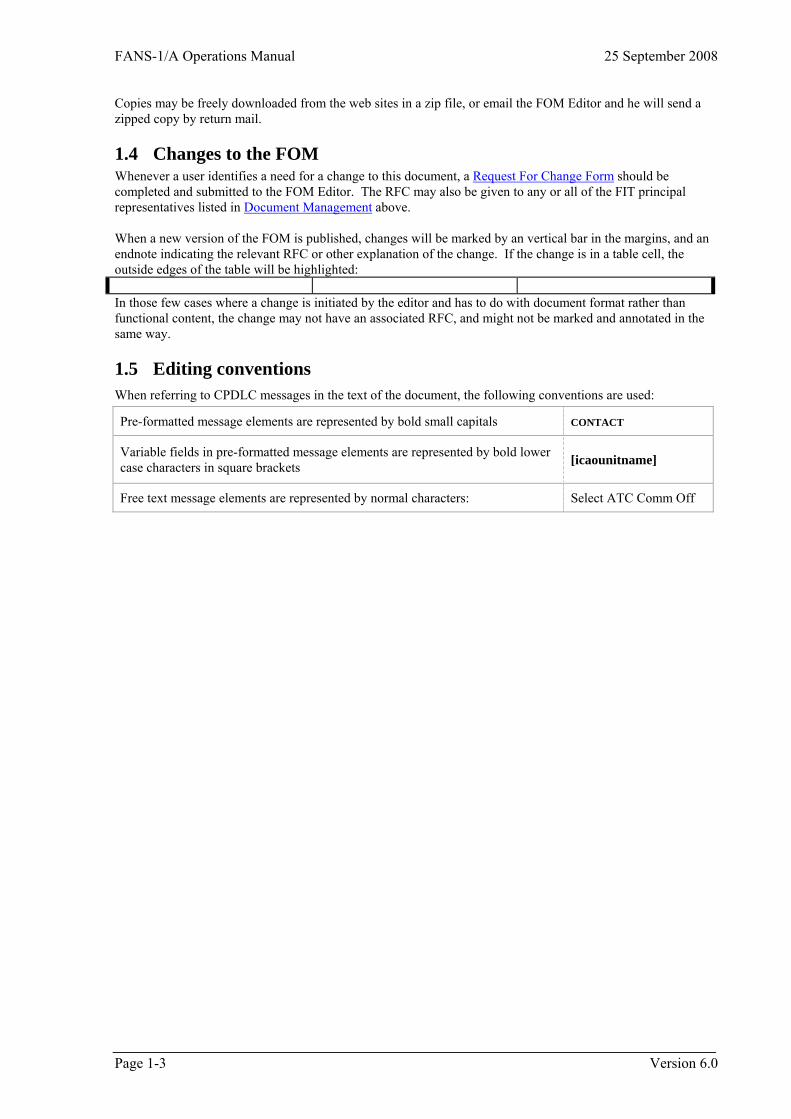
1.5 Editing conventions When referring to CPDLC messages in the text of the document, the following conventions are used:
Pre-formatted message elements are represented by bold small capitals CONTACT
Variable fields in pre-formatted message elements are represented by bold lower case characters in square brackets [icaounitname]
Free text message elements are represented by normal characters: Select ATC Comm Off
Page 1-3 Version 6.0
25 September 2008 FANS-1/A Operations Manual
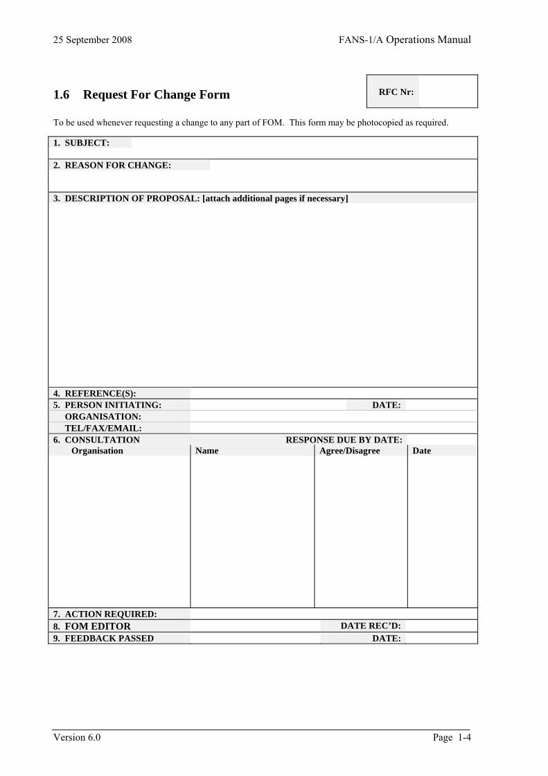
1.6 Request For Change Form
RFC Nr:
To be used whenever requesting a change to any part of FOM. This form may be photocopied as required. 1. SUBJECT: 2. REASON FOR CHANGE: 3. DESCRIPTION OF PROPOSAL: [attach additional pages if necessary] 4. REFERENCE(S): 5. PERSON INITIATING: DATE: ORGANISATION: TEL/FAX/EMAIL: 6. CONSULTATION RESPONSE DUE BY DATE: Organisation Name Agree/Disagree Date
7. ACTION REQUIRED: 8. FOM EDITOR DATE REC’D: 9. FEEDBACK PASSED DATE:
Version 6.0 Page 1-4
FANS-1/A Operations Manual 25 September 2008
Page 1-5 Version 6.0
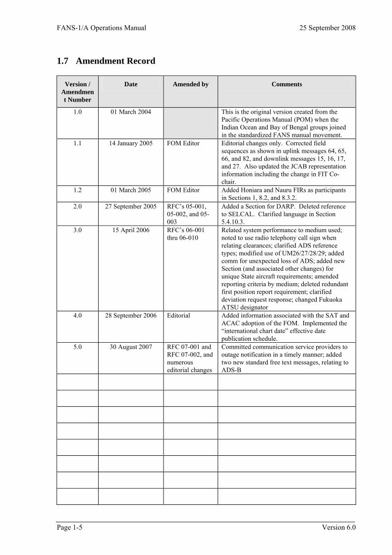
1.7 Amendment Record
Version / Amendment Number
Date Amended by Comments
1.0 01 March 2004 This is the original version created from the Pacific Operations Manual (POM) when the Indian Ocean and Bay of Bengal groups joined in the standardized FANS manual movement.
1.1 14 January 2005 FOM Editor Editorial changes only. Corrected field sequences as shown in uplink messages 64, 65, 66, and 82, and downlink messages 15, 16, 17, and 27. Also updated the JCAB representation information including the change in FIT Co-chair.
1.2 01 March 2005 FOM Editor Added Honiara and Nauru FIRs as participants in Sections 1, 8.2, and 8.3.2.
2.0 27 September 2005 RFC’s 05-001, 05-002, and 05-003
Added a Section for DARP. Deleted reference to SELCAL. Clarified language in Section 5.4.10.3.
3.0 15 April 2006 RFC’s 06-001 thru 06-010
Related system performance to medium used; noted to use radio telephony call sign when relating clearances; clarified ADS reference types; modified use of UM26/27/28/29; added comm for unexpected loss of ADS; added new Section (and associated other changes) for unique State aircraft requirements; amended reporting criteria by medium; deleted redundant first position report requirement; clarified deviation request response; changed Fukuoka ATSU designator
4.0 28 September 2006 Editorial Added information associated with the SAT and ACAC adoption of the FOM. Implemented the “international chart date” effective date publication schedule.
5.0 30 August 2007 RFC 07-001 and RFC 07-002, and numerous editorial changes
Committed communication service providers to outage notification in a timely manner; added two new standard free text messages, relating to ADS-B

FANS-1/A Operations Manual 25 September 2008
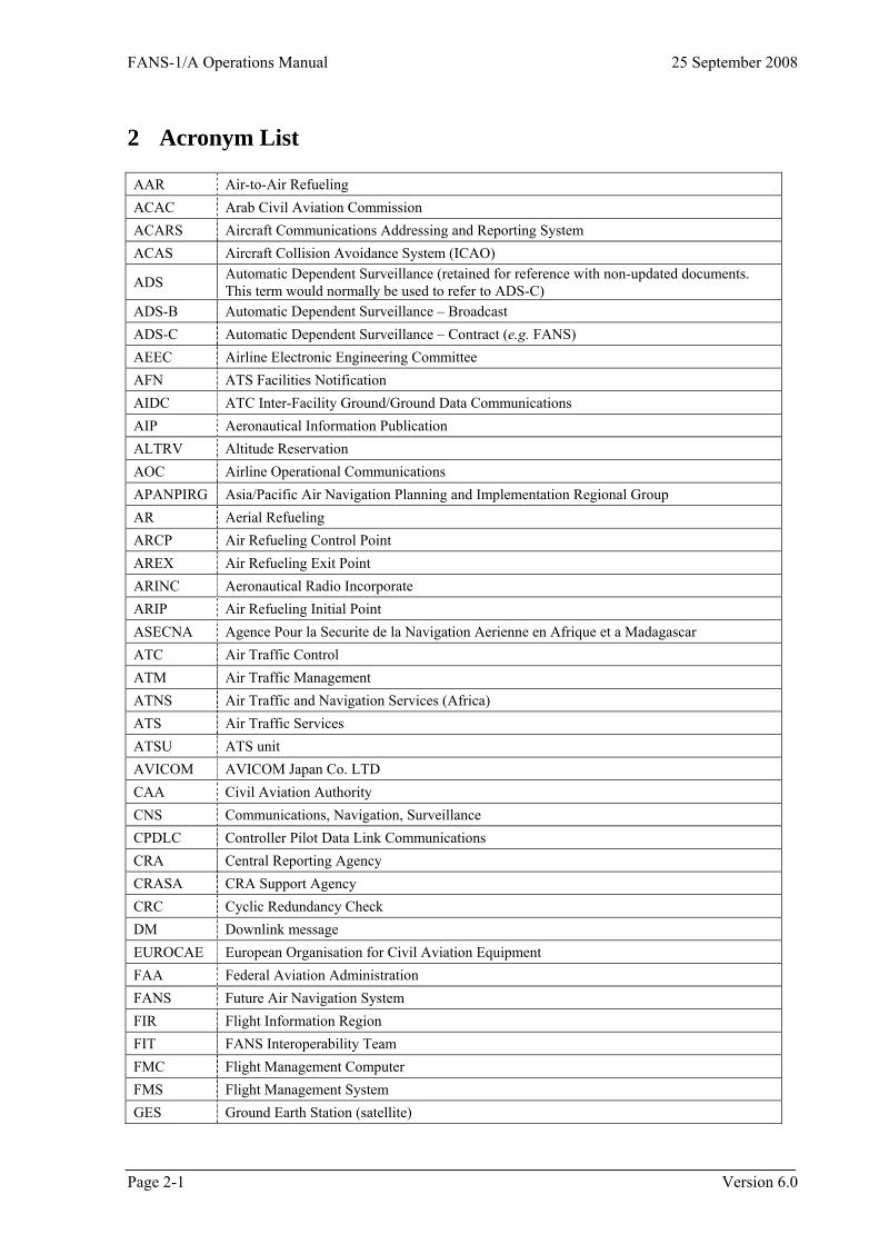
2 Acronym List AAR Air-to-Air Refueling ACAC Arab Civil Aviation Commission ACARS Aircraft Communications Addressing and Reporting System ACAS Aircraft Collision Avoidance System (ICAO)
ADS Automatic Dependent Surveillance (retained for reference with non-updated documents. This term would normally be used to refer to ADS-C)
ADS-B Automatic Dependent Surveillance – Broadcast ADS-C Automatic Dependent Surveillance – Contract (e.g. FANS) AEEC Airline Electronic Engineering Committee AFN ATS Facilities Notification AIDC ATC Inter-Facility Ground/Ground Data Communications AIP Aeronautical Information Publication ALTRV Altitude Reservation AOC Airline Operational Communications APANPIRG Asia/Pacific Air Navigation Planning and Implementation Regional Group AR Aerial Refueling ARCP Air Refueling Control Point AREX Air Refueling Exit Point ARINC Aeronautical Radio Incorporate ARIP Air Refueling Initial Point ASECNA Agence Pour la Securite de la Navigation Aerienne en Afrique et a Madagascar ATC Air Traffic Control ATM Air Traffic Management ATNS Air Traffic and Navigation Services (Africa) ATS Air Traffic Services ATSU ATS unit AVICOM AVICOM Japan Co. LTD CAA Civil Aviation Authority CNS Communications, Navigation, Surveillance CPDLC Controller Pilot Data Link Communications CRA Central Reporting Agency CRASA CRA Support Agency CRC Cyclic Redundancy Check DM Downlink message EUROCAE European Organisation for Civil Aviation Equipment FAA Federal Aviation Administration FANS Future Air Navigation System FIR Flight Information Region FIT FANS Interoperability Team FMC Flight Management Computer FMS Flight Management System GES Ground Earth Station (satellite)
Page 2-1 Version 6.0
25 September 2008 FANS-1/A Operations Manual
Version 6.0 Page 2-2
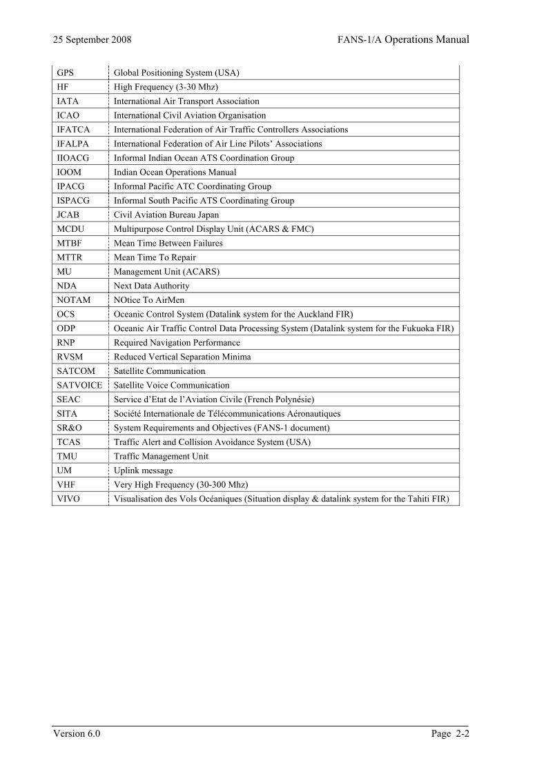
GPS Global Positioning System (USA) HF High Frequency (3-30 Mhz) IATA International Air Transport Association ICAO International Civil Aviation Organisation IFATCA International Federation of Air Traffic Controllers Associations IFALPA International Federation of Air Line Pilots’ Associations IIOACG Informal Indian Ocean ATS Coordination Group IOOM Indian Ocean Operations Manual IPACG Informal Pacific ATC Coordinating Group ISPACG Informal South Pacific ATS Coordinating Group JCAB Civil Aviation Bureau Japan MCDU Multipurpose Control Display Unit (ACARS & FMC) MTBF Mean Time Between Failures MTTR Mean Time To Repair MU Management Unit (ACARS) NDA Next Data Authority NOTAM NOtice To AirMen OCS Oceanic Control System (Datalink system for the Auckland FIR) ODP Oceanic Air Traffic Control Data Processing System (Datalink system for the Fukuoka FIR) RNP Required Navigation Performance RVSM Reduced Vertical Separation Minima SATCOM Satellite Communication SATVOICE Satellite Voice Communication SEAC Service d’Etat de l’Aviation Civile (French Polynésie) SITA Société Internationale de Télécommunications Aéronautiques SR&O System Requirements and Objectives (FANS-1 document) TCAS Traffic Alert and Collision Avoidance System (USA) TMU Traffic Management Unit UM Uplink message VHF Very High Frequency (30-300 Mhz) VIVO Visualisation des Vols Océaniques (Situation display & datalink system for the Tahiti FIR)
FANS-1/A Operations Manual 25 September 2008
3 System Integrity and Monitoring
3.1 Introduction The FANS-1/A CNS/ATM environment is an integrated system including physical systems (hardware, software, and communication networks), human elements (pilots and controllers), and the procedures for use by pilots and controllers. Because of the integrated nature of the system and the degree of interaction among its components, end-to-end system monitoring is required. The procedures described in this section aim to ensure end-to-end system integrity by validation and the identification, reporting and tracking of problems revealed by monitoring. These procedures do not replace the ATS incident reporting procedures and requirements, as specified in ICAO PANS/ATM, Appendix 4; ICAO Air Traffic Services Planning Manual (Doc 9426), Chapter 3; or applicable State regulations, affecting the parties directly involved in a potential ATS incident.
3.2 Personnel Licensing and Training Prior to operating ATC data link communications equipment, pilots and controllers shall receive appropriate training in accordance with Annex 1 and Annex 6 to the Convention on International Civil Aviation. Notwithstanding the above requirement, special arrangements may be made directly between an operator and an ATSU for the purposes of undertaking trials of ATC data link equipment.
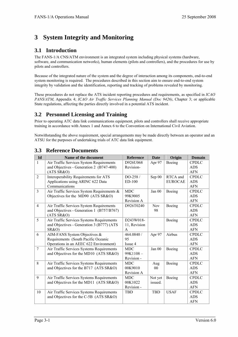
3.3 Reference Documents Id Name of the document Reference Date Origin Domain
1 Air Traffic Services System Requirements and Objectives - Generation 2 (B747-400) (ATS SR&O)
D926U068 Revision-
Apr 97 Boeing CPDLC ADS AFN
2 Interoperability Requirements for ATS Applications using ARINC 622 Data Communications
DO-258 / ED-100
Sep 00 RTCA and EUROCAE
CPDLC ADS AFN
3 Air Traffic Services System Requirements & Objectives for the MD90 (ATS SR&O)
MDC 99K9005 Revision A
Jan 00 Boeing CPDLC ADS AFN
4 Air Traffic Services System Requirements and Objectives - Generation 1 (B757/B767) (ATS SR&O)
D926T0240 Nov 98
Boeing CPDLC ADS AFN
5 Air Traffic Services Systems Requirements and Objectives - Generation 3 (B777) (ATS SR&O)
D243W018-11, Revision A
Boeing CPDLC ADS AFN
6 AIM-FANS System Objectives & Requirements (South Pacific Oceanic Operations in an AEEC 622 Environment)
464.0840 / 95 Issue 4
Apr 97 Airbus
CPDLC ADS AFN
7 Air Traffic Services Systems Requirements and Objectives for the MD10 (ATS SR&O)
MDC 99K1108 – Revision -
Jan 00 Boeing CPDLC ADS AFN
8 Air Traffic Services Systems Requirements and Objectives for the B717 (ATS SR&O)
MDC 00K9010 Revision A
Aug 00
Boeing CPDLC ADS AFN
9 Air Traffic Services Systems Requirements and Objectives for the MD11 (ATS SR&O)
MDC 00K1022 Revision -
Not yet issued.
Boeing CPDLC ADS AFN
10 Air Traffic Services Systems Requirements and Objectives for the C-5B (ATS SR&O)
TBD TBD USAF CPDLC ADS AFN
Page 3-1 Version 6.0
25 September 2008 FANS-1/A Operations Manual
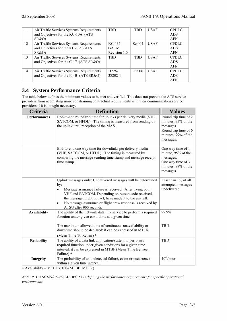
11 Air Traffic Services Systems Requirements and Objectives for the KC-10A (ATS SR&O)
TBD TBD USAF CPDLC ADS AFN
12 Air Traffic Services Systems Requirements and Objectives for the KC-135 (ATS SR&O)
KC-135 GATM Revision 1.0
Sep 04 USAF CPDLC ADS AFN
13 Air Traffic Services Systems Requirements and Objectives for the C-17 (ATS SR&O)
TBD TBD USAF CPDLC ADS AFN
14 Air Traffic Services Systems Requirements and Objectives for the E-4B (ATS SR&O)
D226-38202-1
Jun 06 USAF CPDLC ADS AFN
3.4 System Performance Criteria The table below defines the minimum values to be met and verified. This does not prevent the ATS service providers from negotiating more constraining contractual requirements with their communication service providers if it is thought necessary.
Criteria Definition Values Performances End-to-end round trip time for uplinks per delivery media (VHF,
SATCOM, or HFDL). The timing is measured from sending of the uplink until reception of the MAS.
Round trip time of 2 minutes, 95% of the messages. Round trip time of 6 minutes, 99% of the messages.
End-to-end one way time for downlinks per delivery media (VHF, SATCOM, or HFDL). The timing is measured by comparing the message sending time stamp and message receipt time stamp.
One way time of 1 minute, 95% of the messages. One way time of 3 minutes, 99% of the messages
Uplink messages only: Undelivered messages will be determined by: • Message assurance failure is received. After trying both
VHF and SATCOM. Depending on reason code received, the message might, in fact, have made it to the aircraft.
• No message assurance or flight crew response is received by ATSU after 900 seconds
Less than 1% of all attempted messages undelivered
Availability The ability of the network data link service to perform a required function under given conditions at a given time: The maximum allowed time of continuous unavailability or downtime should be declared: it can be expressed in MTTR (Mean Time To Repair) ∗
99.9% TBD
Reliability The ability of a data link application/system to perform a required function under given conditions for a given time interval: it can be expressed in MTBF (Mean Time Between Failure) *
TBD
Integrity The probability of an undetected failure, event or occurrence within a given time interval.
10-6/hour
∗ Availability = MTBF x 100/(MTBF+MTTR) Note: RTCA SC189/EUROCAE WG 53 is defining the performance requirements for specific operational environments.
Version 6.0 Page 3-2
FANS-1/A Operations Manual 25 September 2008
3.5 ATC System Validation To meet system integrity requirements, States shall consider a validation process that confirms the integrity of their equipment and procedures. The processes shall include: a) A system safety assessment which demonstrates that the ATS Provider’s system will meet the safety
objectives; b) Integration test results confirming interoperability for operational use of airborne and ground systems; and c) Confirmation that the ATS Operation Manuals are compatible with those of adjacent providers.
3.5.1 System safety assessment The system safety assessment can be achieved through a functional hazard analysis or a documented system safety case. This should be conducted for initial implementation as well as for future enhancements and should include: a) Identifying failure conditions; b) Assigning levels of criticality; c) Determining probabilities for occurrence; and d) Identifying mitigating measures. Following on from the safety assessment, States should institute measures to offset the identified failure conditions, or reduce the probability of their occurrence to an acceptable level. This could be accomplished through automation or procedures.
3.5.2 Integration test States should conduct trials with aircraft to ensure that they meet the technical requirements for interoperability previously specified in this document.
3.5.3 ATS operation manuals States should coordinate with adjacent States to confirm that their ATS Operation Manuals contain standard operating procedures.
3.5.4 ATS System Integrity With the implementation of automated ATS control systems, data changes, software upgrades, and system failures can impact on adjacent units. a) ATSUs shall ensure that suitable procedures are in place to ensure that data is correct and accurate, including any changes thereto, and that security of such data is not compromised. b) ATSUs shall also formalise procedures for timely notification to adjacent units of system failures, software upgrades (or downgrades) or other changes, which may impact on surrounding ATS units. Such notification procedures will normally be detailed in Letters of Agreement between adjacent units.
3.6 System Monitoring Routine collection of data is necessary in order to ensure that the system continues to meet its performance, safety and interoperability requirements, and that operations and procedures are working as planned. The monitoring program is a two-fold process. First, summary statistical data should be produced periodically showing the performance of the system. This is accomplished through FANS-1/A Periodic Status Reports. In addition, as problems or abnormalities arise, they should be identified, tracked, analyzed, corrected and information disseminated as required, utilizing the FANS-1/A Problem Report. This process should remain in effect until the system conforms as planned.
Page 3-3 Version 6.0
25 September 2008 FANS-1/A Operations Manual
3.6.1 The monitoring process When problems or abnormalities are discovered, the initial analysis should be performed by the organization(s) identifying the problem. In addition, a copy of the problem report should be sent to the Central Reporting Agency (CRA) which will assign a tracking number. As some problems or abnormalities may involve more than one organization, the originator should be responsible for follow-up action to rectify the problem and forward the information to the CRA. It is essential that all information relating to the problem is documented and recorded and resolved in a timely manner. The parties who need to be involved in this monitoring process and problem tracking for the review and analysis of the data collected are: a) ATS service providers or organizations responsible for ATS system maintenance (where different from the
ATS provider); b) State regulatory authorities; c) Communication service providers; d) Aircraft operators; and e) Aircraft and avionics manufacturers.
3.6.2 Dispatch of confidential information It is important that information that may have an operational impact on other parties be distributed to all users as soon as possible. In this way, each party is made aware of problems already encountered by others, and may be able to contribute further information to aid in the solution of these problems. Before dissemination of information, all references that could identify particular parties are removed by the CRA.
3.6.3 FANS-1/A problem reports Problem reports may originate from many sources, but most will fall within two categories; reports based on observation of one or more specific events, or reports generated from the routine analysis of data. For example, a problem report could arise from an incident where there was confusion about the meaning of a clearance, as the result of inappropriate use of free text. The user would document the problem, resolve it with the appropriate party and forward a copy of the report to the CRA for tracking. This one incident may appear to be an isolated case, but the receipt of numerous similar reports by the CRA that could indicate an area that needs more detailed examination. To effectively resolve problems and track progress, the forms should be sent to the nominated point of contact at the appropriate organization and the CRA. The resolution of the identified problems may require: a) Re-training of system operators, or revision of training procedures to ensure compliance with existing
procedures; b) Change to operating procedures; c) Change to system requirements, including performance and interoperability; or d) Change to system design.
3.6.4 FANS-1/A periodic status report The ATS Providers should complete the FANS-1/A Periodic Status Report at specified intervals agreed by the regional FANS Interoperability Team (FIT) for the dissemination of information and as an indication of system performance. Additionally, the report should identify any trend discovered in system deficiencies, the resultant operational implications, and the resolution, if applicable. Communications service providers are also expected to submit FANS-1/A Periodic Status Reports on the performance of their networks at specified intervals. These reports may contain planned or current upgrades to the systems and may not be required as often as the reports from ATS providers.
3.6.5 Processing of reports Each party to the monitoring process should nominate a single point of contact for receipt of problem reports and coordination with the other parties. This list should be distributed to all parties to the monitoring process. Each State should establish mechanisms within its ATS provider and regulatory authority to:
Version 6.0 Page 3-4
FANS-1/A Operations Manual 25 September 2008
a) Assess problem reports and refer them to the appropriate technical or operational expertise for investigation and resolution;
b) Coordinate with communication service providers and aircraft manufacturers; c) Develop interim operational procedures to mitigate the effects of problems until such time as the problem is
resolved; d) Monitor the progress of problem resolution; e) Prepare summaries of problems encountered and their operational implications and forward these to the
central reporting agency; and f) Prepare the FANS-1/A periodic status report at pre-determined times and forward these to the Central
Reporting Agency.
3.7 FANS Interoperability Team The FANS Interoperability Teams (FITs) shall oversee the monitoring process to ensure the FANS-1/A system continues to meet its performance, safety, and interoperability requirements and that operations and procedures are working as planned. The FITs: a) review de-identified problem reports and determine appropriate resolution; b) develop interim operational procedures to mitigate the effects of problems until such time as they are
resolved; c) monitor the progress of problem resolution; d) prepare summaries of problems encountered and their operational implications; e) assess system performance based on information in CRA periodic reports; and f) authorize and coordinate system testing. FIT members are listed at Section 8.7.
3.8 Central Reporting Agency The Central Reporting Agencies (CRAs) are organizations tasked with the regular dissemination of de-identified statistical data based on monthly status reports received from FIT members. The CRAs track problem reports and publish de-identified information from those reports for dissemination to FIT members. Problem resolution is the responsibility of the appropriate FIT members. The CRAs: a) prepare consolidated problem summaries, with references to particular States and operators removed, for
dissemination to all interested parties; b) collect and consolidate FANS-1/A Periodic Status Reports and disseminates these to all interested parties; c) examine all data to identify trends; and d) prepare an annual report for the FIT. Following review by the FIT, the report will be presented to APANPIRG by the IPACG/ISPACG Co-chairs. This report contains:
• a summary of the system performance based on the periodic status reports; • a summary of the numbers and categories of problems reported; and • a report of progress with rectification of significant problems.
CRA members are listed at Section 8.8.
3.9 Local Data Recording and Analysis
3.9.1 Data recording ATS providers and communication service providers shall retain the records defined below for at least 15 days to allow for accident/incident investigation purposes. (The providers are strongly encouraged to retain the records for at least 30 days.) These records shall be made available for air safety investigative purposes on demand. These recordings shall allow replaying of the situation and identification of the messages that were sent or received by the ATS system.
Page 3-5 Version 6.0
25 September 2008 FANS-1/A Operations Manual
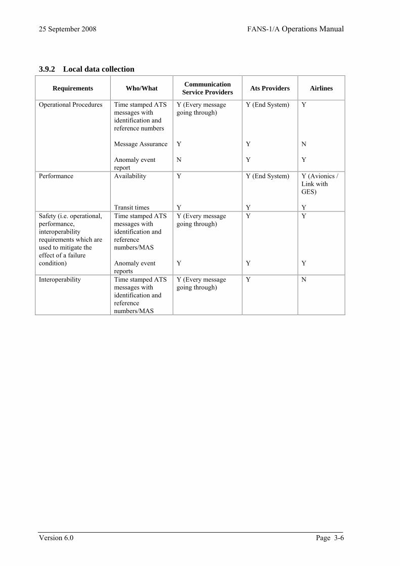
3.9.2 Local data collection
Requirements Who/What Communication Service Providers Ats Providers Airlines
Operational Procedures Time stamped ATS messages with identification and reference numbers Message Assurance Anomaly event report
Y (Every message going through) Y N
Y (End System) Y Y
Y N Y
Performance Availability Transit times
Y Y
Y (End System) Y
Y (Avionics / Link with GES) Y
Safety (i.e. operational, performance, interoperability requirements which are used to mitigate the effect of a failure condition)
Time stamped ATS messages with identification and reference numbers/MAS Anomaly event reports
Y (Every message going through) Y
Y Y
Y Y
Interoperability Time stamped ATS messages with identification and reference numbers/MAS
Y (Every message going through)
Y N
Version 6.0 Page 3-6
FANS-1/A Operations Manual 25 September 2008
3.10 Reporting FANS Problems 3 The use of electronic (ACARS) reporting of problems is encouraged. FMS pages to enable this are available on several Boeing models, and electronic reporting has been in use by Air New Zealand for some time. operators should contact either Boeing or Air New Zealand for more information and assistance in transitioning away fro the paper form When reporting manually, the standard FANS-1/A Problem Report form should be used, as described below,
Page 3-7 Version 6.0
25 September 2008 FANS-1/A Operations Manual
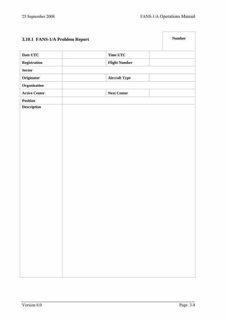
3.10.1 FANS-1/A Problem Report
Number
Date UTC Time UTC
Registration Flight Number
Sector
Originator Aircraft Type
Organization
Active Center Next Center
Position Description
Version 6.0 Page 3-8
FANS-1/A Operations Manual 25 September 2008
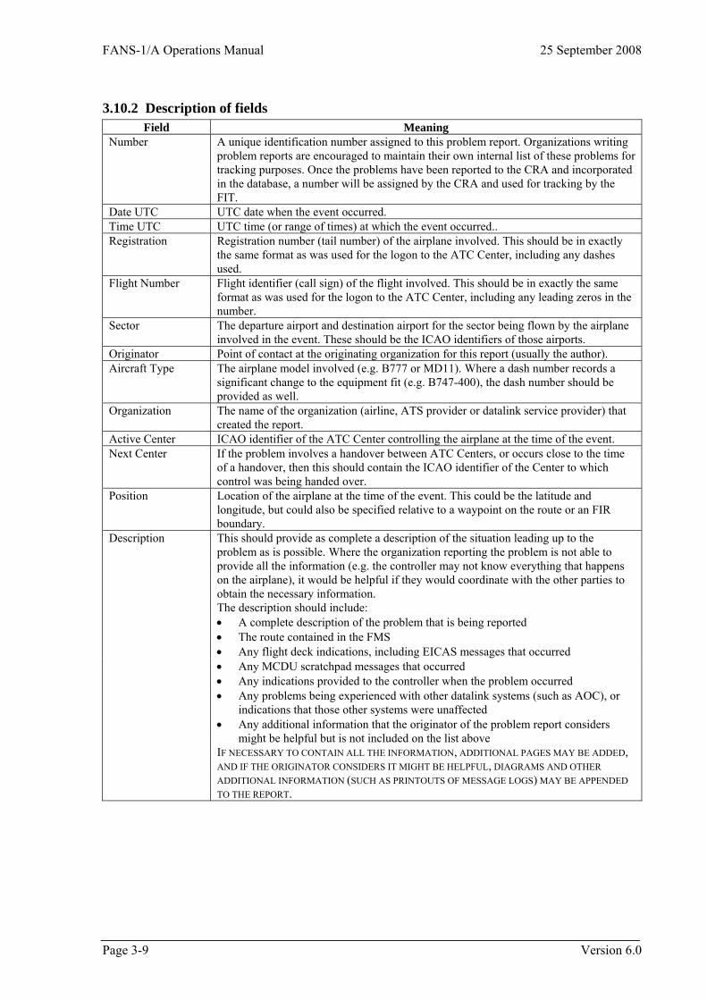
3.10.2 Description of fields Field Meaning
Number A unique identification number assigned to this problem report. Organizations writing problem reports are encouraged to maintain their own internal list of these problems for tracking purposes. Once the problems have been reported to the CRA and incorporated in the database, a number will be assigned by the CRA and used for tracking by the FIT.
Date UTC UTC date when the event occurred. Time UTC UTC time (or range of times) at which the event occurred.. Registration Registration number (tail number) of the airplane involved. This should be in exactly
the same format as was used for the logon to the ATC Center, including any dashes used.
Flight Number Flight identifier (call sign) of the flight involved. This should be in exactly the same format as was used for the logon to the ATC Center, including any leading zeros in the number.
Sector The departure airport and destination airport for the sector being flown by the airplane involved in the event. These should be the ICAO identifiers of those airports.
Originator Point of contact at the originating organization for this report (usually the author). Aircraft Type The airplane model involved (e.g. B777 or MD11). Where a dash number records a
significant change to the equipment fit (e.g. B747-400), the dash number should be provided as well.
Organization The name of the organization (airline, ATS provider or datalink service provider) that created the report.
Active Center ICAO identifier of the ATC Center controlling the airplane at the time of the event. Next Center If the problem involves a handover between ATC Centers, or occurs close to the time
of a handover, then this should contain the ICAO identifier of the Center to which control was being handed over.
Position Location of the airplane at the time of the event. This could be the latitude and longitude, but could also be specified relative to a waypoint on the route or an FIR boundary.
Description This should provide as complete a description of the situation leading up to the problem as is possible. Where the organization reporting the problem is not able to provide all the information (e.g. the controller may not know everything that happens on the airplane), it would be helpful if they would coordinate with the other parties to obtain the necessary information. The description should include: • A complete description of the problem that is being reported • The route contained in the FMS • Any flight deck indications, including EICAS messages that occurred
• Any MCDU scratchpad messages that occurred • Any indications provided to the controller when the problem occurred • Any problems being experienced with other datalink systems (such as AOC), or
indications that those other systems were unaffected • Any additional information that the originator of the problem report considers
might be helpful but is not included on the list above IF NECESSARY TO CONTAIN ALL THE INFORMATION, ADDITIONAL PAGES MAY BE ADDED, AND IF THE ORIGINATOR CONSIDERS IT MIGHT BE HELPFUL, DIAGRAMS AND OTHER ADDITIONAL INFORMATION (SUCH AS PRINTOUTS OF MESSAGE LOGS) MAY BE APPENDED TO THE REPORT.
Page 3-9 Version 6.0

25 September 2008 FANS-1/A Operations Manual
Version 6.0 Page 3-10
3.11 FANS-1/A Periodic Status Report Form Originating Organization
Date of submission Originator
Status for [Month/Year]
Performance Measure Data
DELAY All times will be calculated “less than” < the time band to the right.
Uplinks: Round-trip transit delay time (ATS Provider - delay between the time a message is sent and the time the Message Assurance (MAS) referring to this message is received) (Network provider - delay between the time a message arrives at the router and the time the MAS referring to this message arrives back at the router) Note: If access to individual message delivery media (VHF, SATCOM, HF) is not available to an individual ATSP then a report containing the total uplinks per time bands, total messages sent, and total lost messages for all media combined is acceptable.
Number of messages with a round trip transit delay time of less than X seconds: VHF Data Link (Individual records for CPDLC and ADS messages if possible) X= 10s 20s 30s 60s 90s 120s 180s >180s Total number of VHF uplink messages: Total number of VHF lost uplink messages: SATCOM Data Link: (Individual records for CPDLC and ADS messages if possible) X= 10s 20s 30s 60s 90s 120s 180s >180s Total number of SATCOM uplink messages: Total number of SATCOM lost uplink messages: HF Data Link: (Individual records for CPDLC and ADS messages if possible) X= 10s 20s 30s 60s 90s 120s 180s >180s Total number of HF uplink messages: Total number of HF lost uplink messages:
Downlinks: (ATS Provider - difference between embedded message time stamp and time message received from Network provider)
Lost messages determined by:
• Message assurance failure is received. After trying both VHF and SATCOM. Depending on reason code received, the message might, in fact, have made it to the aircraft.
• No message assurance or flight crew response is received by ATSU after 900 seconds
Note: If access to individual message delivery media (VHF, SATCOM, HF) is not available to an individual ATSP then a report containing the total downlinks per time bands, total messages sent, and total lost messages for all media combined is acceptable.
Number of messages with a downlink transit delay time of less than Y seconds: VHF Data Link: Y= 10s 15s 30s 45s 60s 90s > 90s Total number of VHF downlink messages: Total number of VHF lost downlink messages: SATCOM Data Link: Y= 10s 15s 30s 45s 60s 90s > 90s Total number of SATCOM downlink messages: Total number of SATCOM lost downlink messages: HF Data Link: Y= 10s 15s 30s 45s 60s 90s > 90s Total number of HF downlink messages: Total number of HF lost downlink messages:
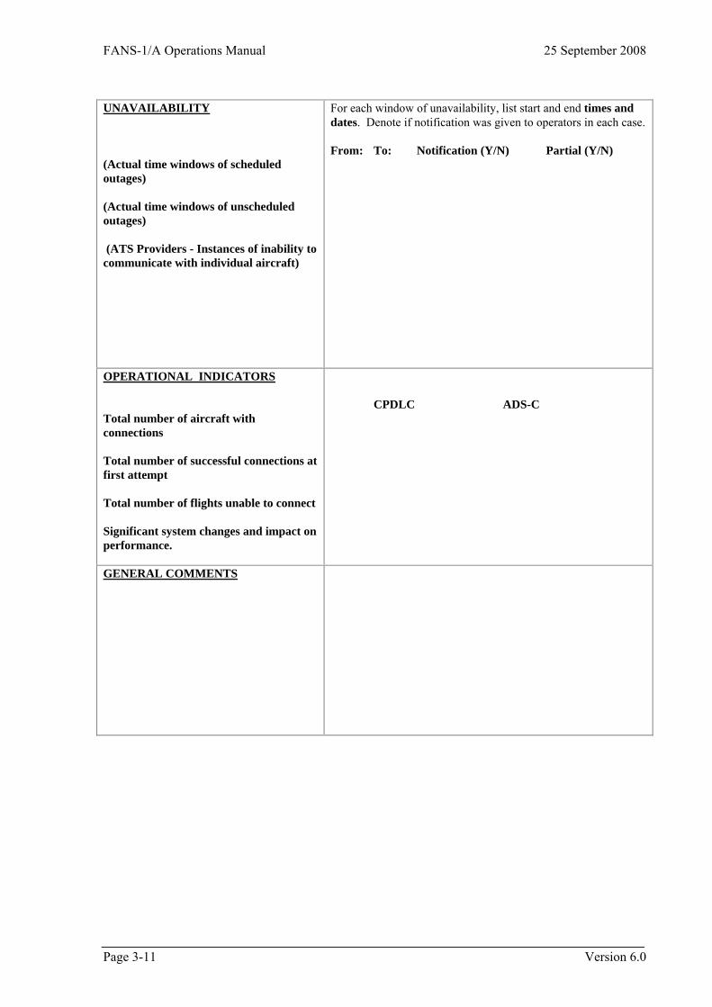
FANS-1/A Operations Manual 25 September 2008
Page 3-11 Version 6.0
UNAVAILABILITY (Actual time windows of scheduled outages) (Actual time windows of unscheduled outages) (ATS Providers - Instances of inability to communicate with individual aircraft)
For each window of unavailability, list start and end times and dates. Denote if notification was given to operators in each case. From: To: Notification (Y/N) Partial (Y/N)
OPERATIONAL INDICATORS Total number of aircraft with connections Total number of successful connections at first attempt Total number of flights unable to connect Significant system changes and impact on performance.
CPDLC ADS-C
GENERAL COMMENTS

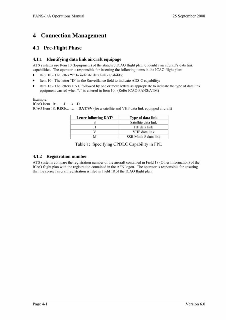
FANS-1/A Operations Manual 25 September 2008
4 Connection Management
4.1 Pre-Flight Phase
4.1.1 Identifying data link aircraft equipage ATS systems use Item 10 (Equipment) of the standard ICAO flight plan to identify an aircraft’s data link capabilities. The operator is responsible for inserting the following items in the ICAO flight plan: • Item 10 - The letter “J” to indicate data link capability; • Item 10 - The letter “D” in the Surveillance field to indicate ADS-C capability; • Item 18 - The letters DAT/ followed by one or more letters as appropriate to indicate the type of data link
equipment carried when “J” is entered in Item 10. (Refer ICAO PANS/ATM) Example: ICAO Item 10: .......J......./…D ICAO Item 18: REG/..……...DAT/SV (for a satellite and VHF data link equipped aircraft)
Letter following DAT/ Type of data link S Satellite data link H HF data link V VHF data link M SSR Mode S data link
Table 1: Specifying CPDLC Capability in FPL
4.1.2 Registration number ATS systems compare the registration number of the aircraft contained in Field 18 (Other Information) of the ICAO flight plan with the registration contained in the AFN logon. The operator is responsible for ensuring that the correct aircraft registration is filed in Field 18 of the ICAO flight plan.
Page 4-1 Version 6.0
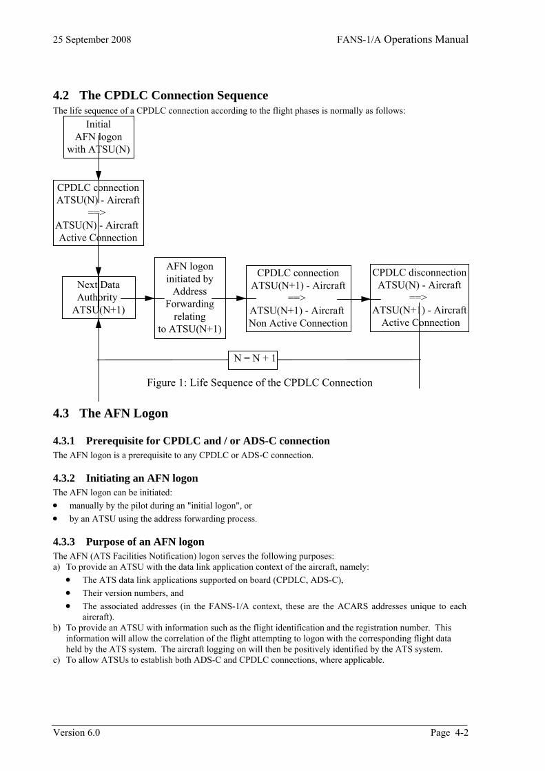
25 September 2008 FANS-1/A Operations Manual
4.2 The CPDLC Connection Sequence The life sequence of a CPDLC connection according to the flight phases is normally as follows:
N = N + 1
CPDLC disconnectionATSU(N) - Aircraft
==> ATSU(N+1) - Aircraft
Active Connection
CPDLC connectionATSU(N) - Aircraft
==> ATSU(N) - Aircraft Active Connection
Next DataAuthority
ATSU(N+1)
CPDLC connectionATSU(N+1) - Aircraft
==> ATSU(N+1) - Aircraft Non Active Connection
InitialAFN logon
with ATSU(N)
AFN logoninitiated by
AddressForwarding
relatingto ATSU(N+1)
Figure 1: Life Sequence of the CPDLC Connection
4.3 The AFN Logon
4.3.1 Prerequisite for CPDLC and / or ADS-C connection The AFN logon is a prerequisite to any CPDLC or ADS-C connection.
4.3.2 Initiating an AFN logon The AFN logon can be initiated: • manually by the pilot during an "initial logon", or • by an ATSU using the address forwarding process.
4.3.3 Purpose of an AFN logon The AFN (ATS Facilities Notification) logon serves the following purposes: a) To provide an ATSU with the data link application context of the aircraft, namely:
• The ATS data link applications supported on board (CPDLC, ADS-C), • Their version numbers, and • The associated addresses (in the FANS-1/A context, these are the ACARS addresses unique to each
aircraft). b) To provide an ATSU with information such as the flight identification and the registration number. This
information will allow the correlation of the flight attempting to logon with the corresponding flight data held by the ATS system. The aircraft logging on will then be positively identified by the ATS system.
c) To allow ATSUs to establish both ADS-C and CPDLC connections, where applicable.
Version 6.0 Page 4-2
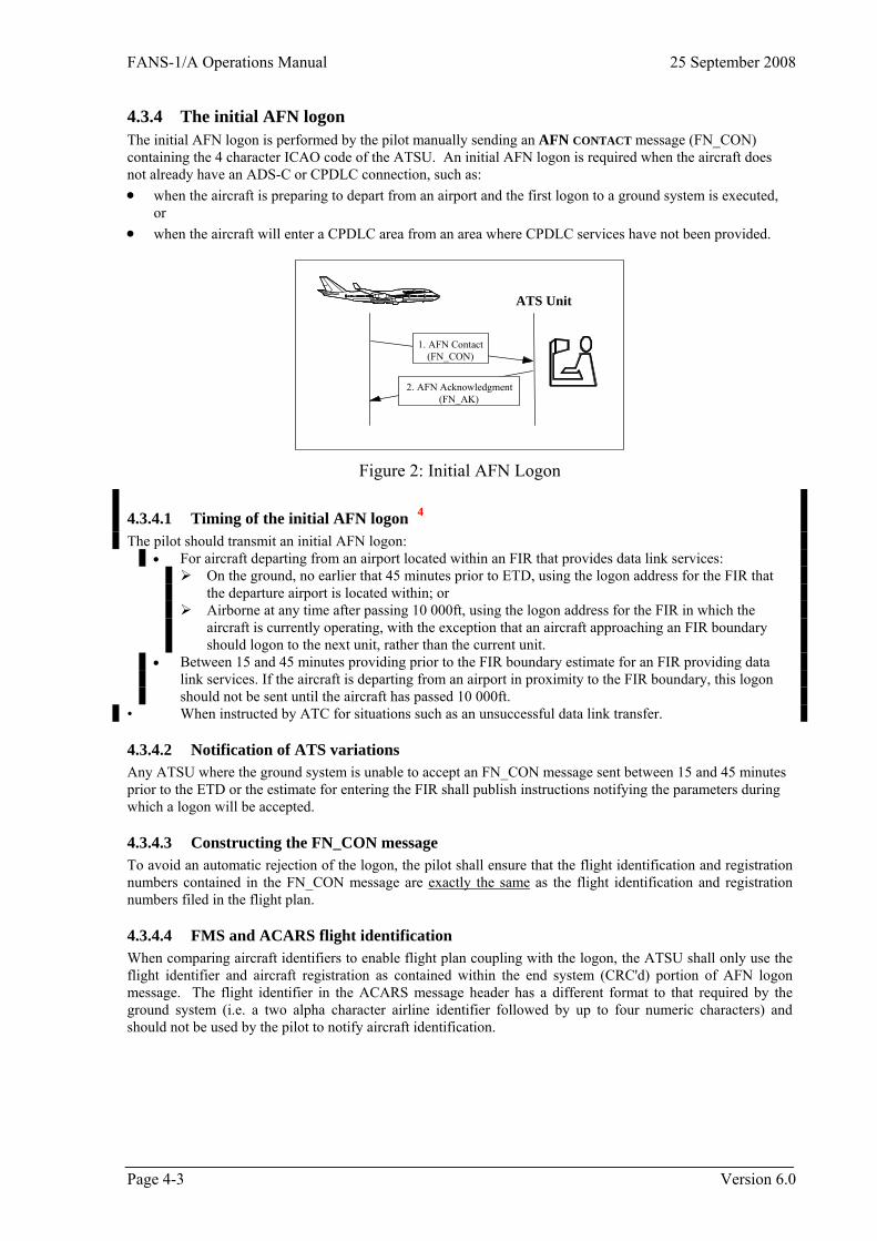
FANS-1/A Operations Manual 25 September 2008
4.3.4 The initial AFN logon The initial AFN logon is performed by the pilot manually sending an AFN CONTACT message (FN_CON) containing the 4 character ICAO code of the ATSU. An initial AFN logon is required when the aircraft does not already have an ADS-C or CPDLC connection, such as: • when the aircraft is preparing to depart from an airport and the first logon to a ground system is executed,
or • when the aircraft will enter a CPDLC area from an area where CPDLC services have not been provided.
1. AFN Contact(FN_CON)
2. AFN Acknowledgment(FN_AK)
ATS Unit
Figure 2: Initial AFN Logon
4.3.4.1 Timing of the initial AFN logon 4 The pilot should transmit an initial AFN logon:
• For aircraft departing from an airport located within an FIR that provides data link services: On the ground, no earlier that 45 minutes prior to ETD, using the logon address for the FIR that
the departure airport is located within; or Airborne at any time after passing 10 000ft, using the logon address for the FIR in which the
aircraft is currently operating, with the exception that an aircraft approaching an FIR boundary should logon to the next unit, rather than the current unit.
• Between 15 and 45 minutes providing prior to the FIR boundary estimate for an FIR providing data link services. If the aircraft is departing from an airport in proximity to the FIR boundary, this logon should not be sent until the aircraft has passed 10 000ft.
• When instructed by ATC for situations such as an unsuccessful data link transfer.
4.3.4.2 Notification of ATS variations Any ATSU where the ground system is unable to accept an FN_CON message sent between 15 and 45 minutes prior to the ETD or the estimate for entering the FIR shall publish instructions notifying the parameters during which a logon will be accepted.
4.3.4.3 Constructing the FN_CON message To avoid an automatic rejection of the logon, the pilot shall ensure that the flight identification and registration numbers contained in the FN_CON message are exactly the same as the flight identification and registration numbers filed in the flight plan.
4.3.4.4 FMS and ACARS flight identification When comparing aircraft identifiers to enable flight plan coupling with the logon, the ATSU shall only use the flight identifier and aircraft registration as contained within the end system (CRC'd) portion of AFN logon message. The flight identifier in the ACARS message header has a different format to that required by the ground system (i.e. a two alpha character airline identifier followed by up to four numeric characters) and should not be used by the pilot to notify aircraft identification.
Page 4-3 Version 6.0
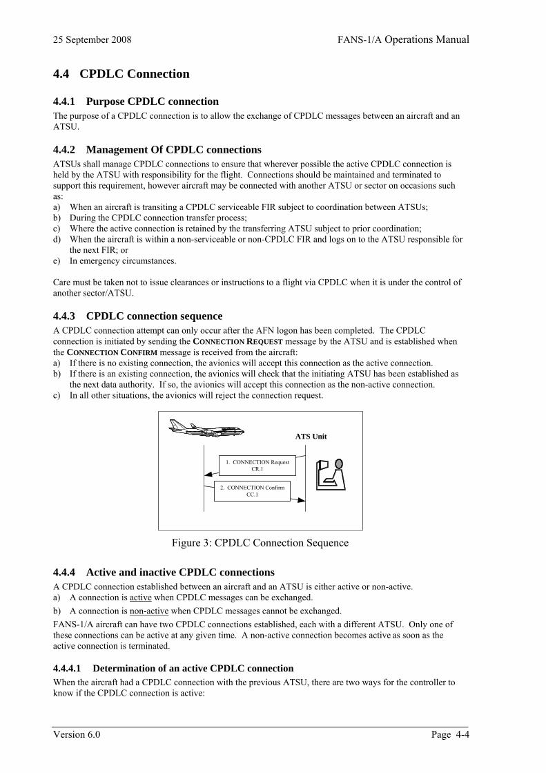
25 September 2008 FANS-1/A Operations Manual
4.4 CPDLC Connection
4.4.1 Purpose CPDLC connection The purpose of a CPDLC connection is to allow the exchange of CPDLC messages between an aircraft and an ATSU.
4.4.2 Management Of CPDLC connections ATSUs shall manage CPDLC connections to ensure that wherever possible the active CPDLC connection is held by the ATSU with responsibility for the flight. Connections should be maintained and terminated to support this requirement, however aircraft may be connected with another ATSU or sector on occasions such as: a) When an aircraft is transiting a CPDLC serviceable FIR subject to coordination between ATSUs; b) During the CPDLC connection transfer process; c) Where the active connection is retained by the transferring ATSU subject to prior coordination; d) When the aircraft is within a non-serviceable or non-CPDLC FIR and logs on to the ATSU responsible for
the next FIR; or e) In emergency circumstances. Care must be taken not to issue clearances or instructions to a flight via CPDLC when it is under the control of another sector/ATSU.
4.4.3 CPDLC connection sequence A CPDLC connection attempt can only occur after the AFN logon has been completed. The CPDLC connection is initiated by sending the CONNECTION REQUEST message by the ATSU and is established when the CONNECTION CONFIRM message is received from the aircraft: a) If there is no existing connection, the avionics will accept this connection as the active connection. b) If there is an existing connection, the avionics will check that the initiating ATSU has been established as
the next data authority. If so, the avionics will accept this connection as the non-active connection. c) In all other situations, the avionics will reject the connection request.
ATS Unit
1. CONNECTION RequestCR.1
2. CONNECTION ConfirmCC.1
Figure 3: CPDLC Connection Sequence
4.4.4 Active and inactive CPDLC connections A CPDLC connection established between an aircraft and an ATSU is either active or non-active. a) A connection is active when CPDLC messages can be exchanged. b) A connection is non-active when CPDLC messages cannot be exchanged. FANS-1/A aircraft can have two CPDLC connections established, each with a different ATSU. Only one of these connections can be active at any given time. A non-active connection becomes active as soon as the active connection is terminated.
4.4.4.1 Determination of an active CPDLC connection When the aircraft had a CPDLC connection with the previous ATSU, there are two ways for the controller to know if the CPDLC connection is active:
Version 6.0 Page 4-4

FANS-1/A Operations Manual 25 September 2008
a) To send a message with the possibility of receiving a NOT CURRENT DATA AUTHORITY error message if the connection is not yet active; or
b) To wait until a CPDLC message is received from the pilot.
Page 4-5 Version 6.0
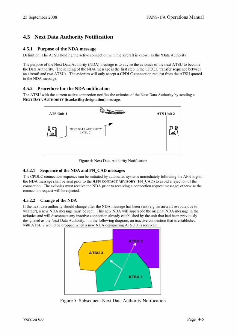
25 September 2008 FANS-1/A Operations Manual
4.5 Next Data Authority Notification
4.5.1 Purpose of the NDA message Definition: The ATSU holding the active connection with the aircraft is known as the ‘Data Authority’. The purpose of the Next Data Authority (NDA) message is to advise the avionics of the next ATSU to become the Data Authority. The sending of the NDA message is the first step in the CPDLC transfer sequence between an aircraft and two ATSUs. The avionics will only accept a CPDLC connection request from the ATSU quoted in the NDA message.
4.5.2 Procedure for the NDA notification The ATSU with the current active connection notifies the avionics of the Next Data Authority by sending a NEXT DATA AUTHORITY [icaofacilitydesignation] message.
ATS Unit 1 ATS Unit 2
NEXT DATA AUTHORITY[ATSU 2]
Figure 4: Next Data Authority Notification
4.5.2.1 Sequence of the NDA and FN_CAD messages The CPDLC connection sequence can be initiated by automated systems immediately following the AFN logon, the NDA message shall be sent prior to the AFN CONTACT ADVISORY (FN_CAD) to avoid a rejection of the connection. The avionics must receive the NDA prior to receiving a connection request message; otherwise the connection request will be rejected.
4.5.2.2 Change of the NDA If the next data authority should change after the NDA message has been sent (e.g. an aircraft re-route due to weather), a new NDA message must be sent. This new NDA will supersede the original NDA message in the avionics and will disconnect any inactive connection already established by the unit that had been previously designated as the Next Data Authority. In the following diagram, an inactive connection that is established with ATSU 2 would be dropped when a new NDA designating ATSU 3 is received.
Figure 5: Subsequent Next Data Authority Notification
Version 6.0 Page 4-6
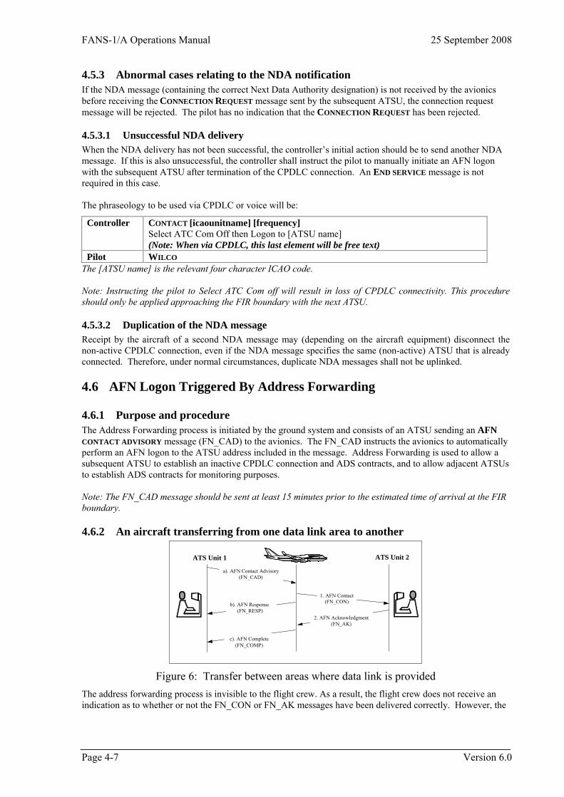
FANS-1/A Operations Manual 25 September 2008
4.5.3 Abnormal cases relating to the NDA notification If the NDA message (containing the correct Next Data Authority designation) is not received by the avionics before receiving the CONNECTION REQUEST message sent by the subsequent ATSU, the connection request message will be rejected. The pilot has no indication that the CONNECTION REQUEST has been rejected.
4.5.3.1 Unsuccessful NDA delivery When the NDA delivery has not been successful, the controller’s initial action should be to send another NDA message. If this is also unsuccessful, the controller shall instruct the pilot to manually initiate an AFN logon with the subsequent ATSU after termination of the CPDLC connection. An END SERVICE message is not required in this case. The phraseology to be used via CPDLC or voice will be:
Controller CONTACT [icaounitname] [frequency] Select ATC Com Off then Logon to [ATSU name] (Note: When via CPDLC, this last element will be free text)
Pilot WILCO The [ATSU name] is the relevant four character ICAO code. Note: Instructing the pilot to Select ATC Com off will result in loss of CPDLC connectivity. This procedure should only be applied approaching the FIR boundary with the next ATSU.
4.5.3.2 Duplication of the NDA message Receipt by the aircraft of a second NDA message may (depending on the aircraft equipment) disconnect the non-active CPDLC connection, even if the NDA message specifies the same (non-active) ATSU that is already connected. Therefore, under normal circumstances, duplicate NDA messages shall not be uplinked.
4.6 AFN Logon Triggered By Address Forwarding
4.6.1 Purpose and procedure The Address Forwarding process is initiated by the ground system and consists of an ATSU sending an AFN CONTACT ADVISORY message (FN_CAD) to the avionics. The FN_CAD instructs the avionics to automatically perform an AFN logon to the ATSU address included in the message. Address Forwarding is used to allow a subsequent ATSU to establish an inactive CPDLC connection and ADS contracts, and to allow adjacent ATSUs to establish ADS contracts for monitoring purposes. Note: The FN_CAD message should be sent at least 15 minutes prior to the estimated time of arrival at the FIR boundary.
4.6.2 An aircraft transferring from one data link area to another
1. AFN Contact(FN_CON)
2. AFN Acknowledgment(FN_AK)
a). AFN Contact Advisory(FN_CAD)
b). AFN Response(FN_RESP)
ATS Unit 1
c). AFN Complete(FN_COMP)
ATS Unit 2
Figure 6: Transfer between areas where data link is provided The address forwarding process is invisible to the flight crew. As a result, the flight crew does not receive an indication as to whether or not the FN_CON or FN_AK messages have been delivered correctly. However, the
Page 4-7 Version 6.0
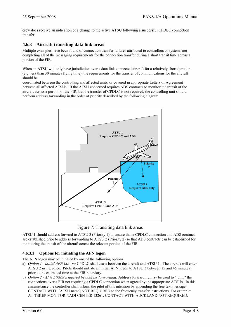
25 September 2008 FANS-1/A Operations Manual
Version 6.0 Page 4-8
crew does receive an indication of a change to the active ATSU following a successful CPDLC connection transfer.
4.6.3 Aircraft transiting data link areas Multiple examples have been found of connection transfer failures attributed to controllers or systems not completing all of the messaging requirements for the connection transfer during a short transit time across a portion of the FIR. When an ATSU will only have jurisdiction over a data link connected aircraft for a relatively short duration (e.g. less than 30 minutes flying time), the requirements for the transfer of communications for the aircraft should be coordinated between the controlling and affected units, or covered in appropriate Letters of Agreement between all affected ATSUs. If the ATSU concerned requires ADS contracts to monitor the transit of the aircraft across a portion of the FIR, but the transfer of CPDLC is not required, the controlling unit should perform address forwarding in the order of priority described by the following diagram.
Figure 7: Transiting data link areas ATSU 1 should address forward to ATSU 3 (Priority 1) to ensure that a CPDLC connection and ADS contracts are established prior to address forwarding to ATSU 2 (Priority 2) so that ADS contracts can be established for monitoring the transit of the aircraft across the relevant portion of the FIR.
4.6.3.1 Options for initiating the AFN logon The AFN logon may be initiated by one of the following options. a) Option 1 - Initial AFN LOGON: CPDLC shall cease between the aircraft and ATSU 1. The aircraft will enter
ATSU 2 using voice. Pilots should initiate an initial AFN logon to ATSU 3 between 15 and 45 minutes prior to the estimated time at the FIR boundary.
b) Option 2 - AFN LOGON triggered by address forwarding: Address forwarding may be used to "jump" the connections over a FIR not requiring a CPDLC connection when agreed by the appropriate ATSUs. In this circumstance the controller shall inform the pilot of this intention by appending the free text message CONTACT WITH [ATSU name] NOT REQUIRED to the frequency transfer instructions For example: AT TEKEP MONITOR NADI CENTER 13261. CONTACT WITH AUCKLAND NOT REQUIRED.
ATSU 2 Requires ADS only
ATSU 3 Requires CPDLC and ADS
ATSU 1 Requires CPDLC and ADS
Priority 1
Priority 2
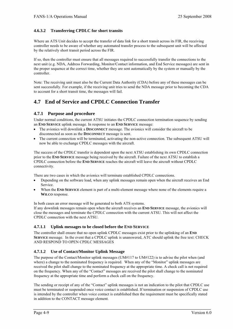
FANS-1/A Operations Manual 25 September 2008
4.6.3.2 Transferring CPDLC for short transits Where an ATS Unit decides to accept the transfer of data link for a short transit across its FIR, the receiving controller needs to be aware of whether any automated transfer process to the subsequent unit will be affected by the relatively short transit period across the FIR. If so, then the controller must ensure that all messages required to successfully transfer the connections to the next unit (e.g. NDA, Address Forwarding, Monitor/Contact information, and End Service messages) are sent in the proper sequence at the correct time, whether they are sent automatically by the system or manually by the controller. Note: The receiving unit must also be the Current Data Authority (CDA) before any of these messages can be sent successfully. For example, if the receiving unit tries to send the NDA message prior to becoming the CDA to account for a short transit time, the messages will fail.
4.7 End of Service and CPDLC Connection Transfer
4.7.1 Purpose and procedure Under normal conditions, the current ATSU initiates the CPDLC connection termination sequence by sending an END SERVICE uplink message. In response to an END SERVICE message: • The avionics will downlink a DISCONNECT message. The avionics will consider the aircraft to be
disconnected as soon as the DISCONNECT message is sent. • The current connection will be terminated, activating the non-active connection. The subsequent ATSU will
now be able to exchange CPDLC messages with the aircraft. The success of the CPDLC transfer is dependent upon the next ATSU establishing its own CPDLC connection prior to the END SERVICE message being received by the aircraft. Failure of the next ATSU to establish a CPDLC connection before the END SERVICE reaches the aircraft will leave the aircraft without CPDLC connectivity. There are two cases in which the avionics will terminate established CPDLC connections. • Depending on the software load, when any uplink messages remain open when the aircraft receives an End
Service. • When the END SERVICE element is part of a multi-element message where none of the elements require a
WILCO response. In both cases an error message will be generated to both ATS systems. If any downlink messages remain open when the aircraft receives an END SERVICE message, the avionics will close the messages and terminate the CPDLC connection with the current ATSU. This will not affect the CPDLC connection with the next ATSU.
4.7.1.1 Uplink messages to be closed before the END SERVICE The controller shall ensure that no open uplink CPDLC messages exist prior to the uplinking of an END SERVICE message. In the event that a CPDLC uplink is unanswered, ATC should uplink the free text: CHECK AND RESPOND TO OPEN CPDLC MESSAGES
4.7.1.2 Use of Contact/Monitor Uplink Message The purpose of the Contact/Monitor uplink messages (UM#117 to UM#122) is to advise the pilot when (and where) a change to the nominated frequency is required. When any of the “Monitor” uplink messages are received the pilot shall change to the nominated frequency at the appropriate time. A check call is not required on the frequency. When any of the “Contact” messages are received the pilot shall change to the nominated frequency at the appropriate time and perform a check call on the frequency. The sending or receipt of any of the “Contact” uplink messages is not an indication to the pilot that CPDLC use must be terminated or suspended once voice contact is established. If termination or suspension of CPDLC use is intended by the controller when voice contact is established then the requirement must be specifically stated in addition to the CONTACT message element.
Page 4-9 Version 6.0
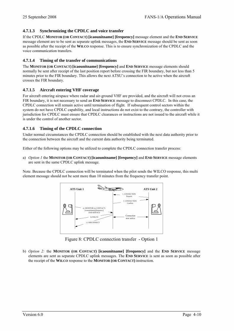
25 September 2008 FANS-1/A Operations Manual
4.7.1.3 Synchronizing the CPDLC and voice transfer If the CPDLC MONITOR (OR CONTACT) [icaounitname] [frequency] message element and the END SERVICE message element are to be sent as separate uplink messages, the END SERVICE message should be sent as soon as possible after the receipt of the WILCO response. This is to ensure synchronization of the CPDLC and the voice communication transfers.
4.7.1.4 Timing of the transfer of communications The MONITOR (OR CONTACT) [icaounitname] [frequency] and END SERVICE message elements should normally be sent after receipt of the last position report before crossing the FIR boundary, but not less than 5 minutes prior to the FIR boundary. This allows the next ATSU’s connection to be active when the aircraft crosses the FIR boundary.
4.7.1.5 Aircraft entering VHF coverage For aircraft entering airspace where radar and air-ground VHF are provided, and the aircraft will not cross an FIR boundary, it is not necessary to send an END SERVICE message to disconnect CPDLC. In this case, the CPDLC connection will remain active until termination of flight. If subsequent control sectors within the system do not have CPDLC capability, and local instructions do not exist to the contrary, the controller with jurisdiction for CPDLC must ensure that CPDLC clearances or instructions are not issued to the aircraft while it is under the control of another sector.
4.7.1.6 Timing of the CPDLC connection Under normal circumstances the CPDLC connection should be established with the next data authority prior to the connection between the aircraft and the current data authority being terminated. Either of the following options may be utilized to complete the CPDLC connection transfer process: a) Option 1 the MONITOR (OR CONTACT) [icaounitname] [frequency] and END SERVICE message elements
are sent in the same CPDLC uplink message. Note. Because the CPDLC connection will be terminated when the pilot sends the WILCO response, this multi element message should not be sent more than 10 minutes from the frequency transfer point.
1. CONNECTIONRequest
a). MONITOR (or CONTACT)[icaounitname][frequency]
END SERVICE
b).WILCO
ATS Unit 1
c). DISCONNECT
ATS Unit 2
2. CONNECTIONConfirm
Connectionnow active
Figure 8: CPDLC connection transfer - Option 1
b) Option 2: the MONITOR (OR CONTACT) [icaounitname] [frequency] and the END SERVICE message
elements are sent as separate CPDLC uplink messages. The END SERVICE is sent as soon as possible after the receipt of the WILCO response to the MONITOR (OR CONTACT) instruction.
Version 6.0 Page 4-10
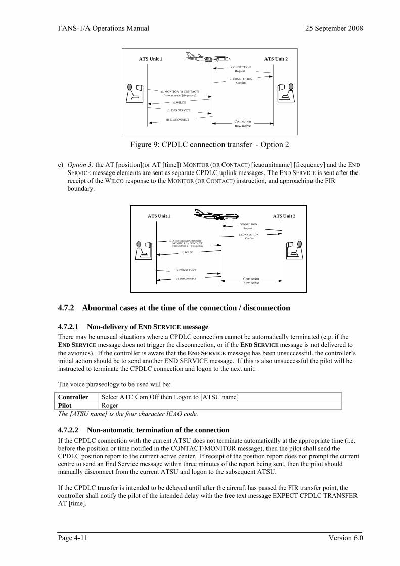
FANS-1/A Operations Manual 25 September 2008
1. CONNECTIONRequest
a). MONITOR (or CONTACT)[icaounitname][frequency]
b).WILCO
ATS Unit 1
d). DISCONNECT
ATS Unit 2
2. CONNECTIONConfirm
c). END SERVICE
Connectionnow active
Figure 9: CPDLC connection transfer - Option 2 c) Option 3: the AT [position](or AT [time]) MONITOR (OR CONTACT) [icaounitname] [frequency] and the END
SERVICE message elements are sent as separate CPDLC uplink messages. The END SERVICE is sent after the receipt of the WILCO response to the MONITOR (OR CONTACT) instruction, and approaching the FIR boundary.
1. CONNEC TIONRequest
a). AT [posit ion] (OR [t ime]) MONITO R (or CONTAC T)
[icaounitnam e ][frequency]
b).WILCO
ATS Unit 1
d). DISCONNECT
ATS Unit 2
2. CONNEC TIONConfirm
c). END SE RVICE
Connectionnow active
4.7.2 Abnormal cases at the time of the connection / disconnection
4.7.2.1 Non-delivery of END SERVICE message There may be unusual situations where a CPDLC connection cannot be automatically terminated (e.g. if the END SERVICE message does not trigger the disconnection, or if the END SERVICE message is not delivered to the avionics). If the controller is aware that the END SERVICE message has been unsuccessful, the controller’s initial action should be to send another END SERVICE message. If this is also unsuccessful the pilot will be instructed to terminate the CPDLC connection and logon to the next unit. The voice phraseology to be used will be:
Controller Select ATC Com Off then Logon to [ATSU name] Pilot Roger The [ATSU name] is the four character ICAO code.
4.7.2.2 Non-automatic termination of the connection If the CPDLC connection with the current ATSU does not terminate automatically at the appropriate time (i.e. before the position or time notified in the CONTACT/MONITOR message), then the pilot shall send the CPDLC position report to the current active center. If receipt of the position report does not prompt the current centre to send an End Service message within three minutes of the report being sent, then the pilot should manually disconnect from the current ATSU and logon to the subsequent ATSU. If the CPDLC transfer is intended to be delayed until after the aircraft has passed the FIR transfer point, the controller shall notify the pilot of the intended delay with the free text message EXPECT CPDLC TRANSFER AT [time].
Page 4-11 Version 6.0

25 September 2008 FANS-1/A Operations Manual
Version 6.0 Page 4-12
If the aircraft crosses the FIR boundary prior to the time notified in the free text uplink, the boundary position will be sent to the ATSU with the active connection. If the CPDLC transfer has not been completed by the time notified in the uplink message, the pilot is entitled to manually disconnect from the active ATSU and logon to the subsequent ATSU.
FANS-1/A Operations Manual 25 September 2008
5 CPDLC Procedures
5.1 Means of Communication
5.1.1 General Generally, when a CPDLC aircraft is operating within a CPDLC airspace beyond the range of VHF voice communications, and other local rules do not apply, then: • CPDLC will be the primary means of communication, and • Voice will be used as the backup communication medium (for example VHF, direct HF, third party HF,
SATVOICE). The response to a CPDLC message should be via CPDLC, and a response to voice should be via voice.
5.1.2 Voice communications
5.1.2.1 Notification of frequencies to the preceding ATSU ATSUs shall advise frequencies to the preceding ATSU, in accordance with the appropriate letters of agreement.
5.1.2.2 Notification of HF frequencies by CPDLC The uplink CPDLC frequency transfer message elements can accommodate only one frequency variable. Due to this limitation, the controller will insert the primary HF frequency in these messages. This applies to the following uplinks: UM#117 CONTACT [icaounitname][frequency] UM#118 AT [position] CONTACT [icaounitname][frequency] UM#119 AT [time] CONTACT [icaounitname][frequency] UM#120 MONITOR [icaounitname][frequency] UM#121 AT [position] MONITOR [icaounitname][frequency] UM#122 AT [time] MONITOR [icaounitname][frequency] In areas of poor HF coverage, the controller may consider appending free text nominating a secondary HF frequency. The format of this message is described in Part 5.9. In the CONTACT and MONITOR messages RADIO is not an option within the [icaounitname] field. Therefore CENTER will be used to identify a RADIO facility.
5.2 CPDLC Capability
5.2.1 Notification of CPDLC capability An AIP Supplement, or similar, shall be published to advise the CPDLC capability of an ATS system and its AFN logon address. An aircraft’s CPDLC capability shall be notified in the flight plan.
5.2.2 Downlink messages ATS systems that allow the use of all elements contained in the FANS-1/A message set should be capable of correctly processing all the FANS-1/A downlink message elements. However, where specific CPDLC implementations do not include all message set elements, such as domestic airspace or initial and temporary situations, the ATSUs involved should publish the reduced message set with appropriate explanatory material. Where these reduced implementations occur across a group of adjoining ATSUs, every attempt should be made to ensure that the message set chosen is common to all applicable airspace within the implementation boundaries. ATSUs should exercise caution when specifying reduced message sets, ensuring that the messages handled are adequate for all envisaged scenarios in the airspace to be served by CPDLC.
Page 5-1 Version 6.0
25 September 2008 FANS-1/A Operations Manual
If the ground system receives a downlink message that is not supported by the implemented message set, then the free text uplink message (UM#169) MESSAGE NOT SUPPORTED BY THIS FACILITY should be sent rather than terminating the connection.
5.2.3 Uplink messages For various reasons some States may not have implemented specific FANS-1/A uplink message elements contained in the message set in Section 5.8 (e.g. UM#33 CRUISE [altitude]). These individual implementations shall not impact overall operations.
5.3 Use of Pre-Formatted and Free Text Messages
5.3.1 Preferred use of pre-formatted messages Free text messages shall be used only when an appropriate pre-formatted message element does not exist. In particular, the creation of a clearance request and the issuing of a clearance shall be performed by the use of pre-formatted message elements only. The use of pre-formatted message elements allows on board data processing such as the automatic insertion of the clearance information into the FMC. It also allows the controller to respond more quickly when the ATS system has the capability to automatically link a pre-formatted request to a pre-formatted response. Additionally, this process minimizes the risk of input errors. When a free text message is required, standard ATC phraseology and format shall be used. Non-essential words and phrases should be avoided. Abbreviations should only be included in free text messages when they form part of standard ICAO phraseology, e.g. ETA.
5.3.2 Standardized free text messages While pre-formatted message elements are required to be used whenever possible, there are occasions where frequent use of free text allows the meaning and appropriate response to be standardized. The Standard Free text message set is shown in Section 5.10.
5.3.3 Storing free text messages ATSUs capable of storing free text messages should select those message elements from the standard free text message set (see FANS-1/A CPDLC Standard Free Text Messages) appropriate to their particular environments. When the storage of free text messages is not possible, controllers shall use the same message formats when typing free text messages.
5.4 Exchange of CPDLC messages
5.4.1 Message assurance The FANS-1/A system does not provide for end-to-end message assurance. Therefore, there can be no guarantee provided by the ground system or the avionics that the message has been delivered to the controller or pilot. However: • The ATS system will receive a network acknowledgment (MAS Message Assurance) to an uplink message
indicating that the message has been delivered to the aircraft’s ACARS MU, and • The avionics will receive a network acknowledgment to a downlink message indicating that the message has
been delivered to the communication service provider’s system.
5.4.2 Ambiguous dialogues In the case of a controller or pilot having any doubt as to the intent of a message, or if any other ambiguity exists, clarification shall be sought through the use of voice communication.
5.4.3 Interruption of a CPDLC dialogue If a CPDLC dialogue is interrupted by a system shutdown, the entire dialogue shall be re-commenced by voice communication.
Version 6.0 Page 5-2
FANS-1/A Operations Manual 25 September 2008
5.4.4 Approval of request or clearance / instruction
5.4.4.1 Affirmative response to a clearance/instruction The WILCO downlink message indicates that the pilot will comply fully with the clearance/instruction contained in the associated uplink message. The readback of a clearance or instruction issued by CPDLC is not required.
5.4.4.2 Affirmative response to a clearance request The ROGER or AFFIRM uplinks are not appropriate responses to a clearance request and shall not be used for this purpose. The controller shall only approve a clearance request by uplinking a message containing an actual clearance.
5.4.4.3 Conditions relating to a specific clearance Terms or conditions relating to a specific clearance shall be included in the clearance uplink message. They shall not be sent as a separate message.
5.4.4.4 Affirmative response to a negotiation request AFFIRM is an appropriate response to an uplinked negotiation request message that is acceptable (e.G. CAN YOU ACCEPT [altitude] AT [time]).
5.4.5 Negative response to a downlink request
5.4.5.1 Negative response to a clearance request When a clearance request is denied, the controller shall use the element UNABLE (not NEGATIVE) in the uplink response. The aircraft’s current clearance shall not be re-stated.
5.4.5.2 Explanation of negative response Pre-formatted elements such as DUE TO TRAFFIC (or a free text element) should be added to the response message if clarification is considered necessary. Additional elements (including free text elements) in the form of an explanation must be included when responding to a multiple clearance request where some, but not all clearance requests can be granted.
5.4.5.3 Offering alternative clearances to downlink requests If the clearance contained in a downlink request is not available, but an alternative (similar) clearance is available, ATC must not simply respond to the downlink request with the alternative uplink clearance. An UNABLE must be uplinked to close the original clearance request. Depending on workload and traffic, ATC may then uplink an alternative clearance. Example: Pilot REQUEST CLIMB TO F370 Controller UNABLE. DUE TO TRAFFIC Controller CLIMB TO AND MAINTAIN F350. REPORT LEVEL F350 The ATC response in the following example is incorrect and should not be used Pilot REQUEST CLIMB TO F370 Controller UNABLE. CLIMB TO AND MAINTAIN F350. REPORT LEVEL F350
5.4.6 Negative response to an uplink request NEGATIVE is an appropriate response to an uplink negotiation request that is not acceptable (e.g. CAN YOU ACCEPT [altitude] AT [time]).
5.4.7 Time period between receiving and responding to a message The controller and the pilot shall respond to incoming requests as soon as practicable to avoid duplicate messages entering the system.
Page 5-3 Version 6.0
25 September 2008 FANS-1/A Operations Manual
5.4.7.1 Delays in responding The controller and the pilot should consider that it takes up to one minute for a message to be received, time for the pilot (or the controller) to take action and respond, and up to one minute for the reply to be received. Nevertheless, they should be aware that extra delays could occur in the transmission of any response to a CPDLC message. Note. Transmission times for messages may vary depending on the transmission media.
5.4.7.2 Delay expected after receiving a “STANDBY” message The intended use of the uplink STANDBY message element is to provide advice to the flight crew that their requested clearance is being assessed, but is not immediately available. This may be due to traffic, delays in coordination with the next sector or ATS unit etc). It should not be used as a means of simply acknowledging that the downlink request has been received by the ATS ground system. 5 If the STANDBY response is received, a further response can be expected within 10 minutes. The message remains open. If the pilot (or the controller) does not respond within this time, the next message should be in the form of an inquiry, not a duplicated request.
5.4.8 Re-sending Messages
5.4.8.1 Re-sending of a message when no alert received When the pilot (or the controller) elects to re-send a message after a reasonable period of time has passed and no error message has been received indicating the non-delivery of the message, the message shall be sent as a query message. Alternatively, voice communication may be used. Example: Pilot REQUEST CLIMB [level] Pilot WHEN CAN I EXPECT [level]
5.4.8.2 Re-sending of a message when an alert has been received When an error message indicating the non-delivery of the message has been received at the flight deck or at the controller work station, the pilot (or the controller) may elect to re-send an identical message. Alternatively, voice may be used.
5.4.9 Duplicate requests received
5.4.9.1 Second identical request after an uplink “STANDBY” message If a second identical downlink request is sent by the pilot after a reasonable period (more than 10 minutes) has passed since receiving a STANDBY response to an earlier request, the controller should respond with UNABLE REQUEST DEFERRED. This will close out the second message, inform the pilot that the reply will take longer, and will leave only one open message requiring a response.
5.4.9.2 Multiple identical requests All messages requiring a response must be answered. If the controller (or the pilot) receives a second identical CPDLC request prior to having answered the first, they shall respond to both of the messages to ensure message closure. On rare occasions, the first uplink message may generate an “invalid reference number” error message, in the avionics.
Version 6.0 Page 5-4
FANS-1/A Operations Manual 25 September 2008
5.4.10 Altitude change clearances
5.4.10.1 Issuing conditional altitude change clearances The potential exists for the restriction “AT” contained at the beginning of the following conditional clearances to be missed by aircrew and consequently the clearance may be executed prematurely. • UM#21 AT [time] CLIMB TO AND MAINTAIN [altitude] • UM#22 AT [position] CLIMB TO AND MAINTAIN [altitude] • UM#24 AT [time] DESCEND TO AND MAINTAIN [altitude] • UM#25 AT [position] DESCEND TO AND MAINTAIN [altitude]
Controllers shall precede UM#21, UM#22, UM#24 and UM#25 with UM#19 MAINTAIN [altitude] indicating to aircrew to maintain their present altitude until the condition of the clearance is satisfied.
5.4.10.2 Level report requirements for climb or descent clearances If a CPDLC level report is required, controllers shall append UM#129 REPORT LEVEL [altitude] to any vertical change clearance to a single altitude so that flight crews have access to the pre-formatted downlink report. If no REPORT LEVEL [altitude] is received, the crew has no requirement to report maintaining the cleared flight level. Example clearance issued to a flight currently cruising at FL310 requesting climb to FL350 when the climb can not be executed until the aircraft is at MICKY MAINTAIN FL310, AT MICKY CLIMB TO AND MAINTAIN FL350, REPORT LEVEL FL350 Note: Some States do not require this CPDLC level report in airspace in which ADS-C is in use.
5.4.10.3 Canceling block altitude clearances A block altitude clearance is an authorization for an aircraft to operate between and at the levels specified in the clearance. A pilot report at the floor or ceiling of the block altitude clearance does not cancel the block altitude clearance – the clearance is only cancelled by the pilot acceptance of a subsequent (vertical) clearance issued by ATC. If the current block altitude clearance is no longer required, the pilot should request the level(s) preferred. To cancel a previously issued block clearance and limit the aircraft to one specific level the controller shall issue an appropriate vertical instruction such as: • UM#19 MAINTAIN [altitude]; • UM#20 CLIMB TO AND MAINTAIN [altitude]; or • UM#28 DESCEND TO REACH [altitude] BY [time]. The controller should also add UM#129 REPORT LEVEL [altitude]. The WILCO response to the vertical clearance uplink cancels any previously issued block clearance.
5.4.10.4 Issuing Level Restrictions Depending on how they are used, certain CPDLC message elements may be used as either:
1. A “stand-alone” clearance; or 2. A level requirement for an interim level, when appended to another CPDLC vertical clearance
This applies to the following message elements:
• UM#26 CLIMB TO REACH [altitude] BY [time] • UM#27 CLIMB TO REACH [altitude] BY [position] • UM#28 DESCEND TO REACH [altitude] BY [time] • UM#29 DESCEND TO REACH [altitude] BY [position]
Page 5-5 Version 6.0
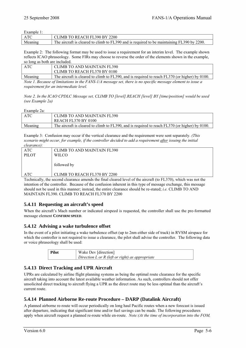
25 September 2008 FANS-1/A Operations Manual
Example 1: ATC CLIMB TO REACH FL390 BY 2200 Meaning The aircraft is cleared to climb to FL390 and is required to be maintaining FL390 by 2200.� Example 2: The following format may be used to issue a requirement for an interim level. The example shown reflects ICAO phraseology. Some FIRs may choose to reverse the order of the elements shown in the example, so long as both are included. ATC CLIMB TO AND MAINTAIN FL390
CLIMB TO REACH FL370 BY 0100 Meaning The aircraft is cleared to climb to FL390, and is required to reach FL370 (or higher) by 0100. Note 1. Because of limitations in the FANS-1/A message set, there is no specific message element to issue a requirement for an intermediate level. Note 2. In the ICAO CPDLC Message set, CLIMB TO [level].REACH [level] BY [time/position] would be used (see Example 2a) Example 2a: ATC CLIMB TO AND MAINTAIN FL390
REACH FL370 BY 0100 Meaning The aircraft is cleared to climb to FL390, and is required to reach FL370 (or higher) by 0100. Example 3: Confusion may occur if the vertical clearance and the requirement were sent separately. (This scenario might occur, for example, if the controller decided to add a requirement after issuing the initial clearance): ATC PILOT ATC
CLIMB TO AND MAINTAIN FL390 WILCO followed by CLIMB TO REACH FL370 BY 2200
Technically, the second clearance amends the final cleared level of the aircraft (to FL370), which was not the intention of the controller. Because of the confusion inherent in this type of message exchange, this message should not be used in this manner; instead, the entire clearance should be re-stated; i.e. CLIMB TO AND MAINTAIN FL390. CLIMB TO REACH FL370 BY 2200
5.4.11 Requesting an aircraft’s speed When the aircraft’s Mach number or indicated airspeed is requested, the controller shall use the pre-formatted message element CONFIRM SPEED.
5.4.12 Advising a wake turbulence offset In the event of a pilot initiating a wake turbulence offset (up to 2nm either side of track) in RVSM airspace for which the controller is not required to issue a clearance, the pilot shall advise the controller. The following data or voice phraseology shall be used:
Pilot Wake Dev [direction] Direction L or R (left or right) as appropriate
5.4.13 Direct Tracking and UPR Aircraft UPRs are calculated by airline flight planning systems as being the optimal route clearance for the specific aircraft taking into account the latest available weather information. As such, controllers should not offer unsolicited direct tracking to aircraft flying a UPR as the direct route may be less optimal than the aircraft’s current route.
5.4.14 Planned Airborne Re-route Procedure – DARP (Datalink Aircraft) A planned airborne re-route will occur periodically on long haul Pacific routes when a new forecast is issued after departure, indicating that significant time and/or fuel savings can be made. The following procedures apply when aircraft request a planned re-route while en-route. Note:(At the time of incorporation into the FOM,
Version 6.0 Page 5-6
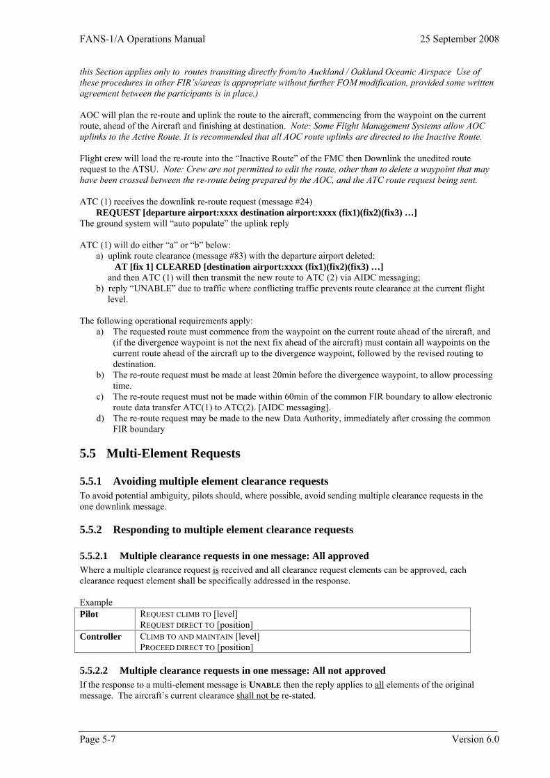
FANS-1/A Operations Manual 25 September 2008
this Section applies only to routes transiting directly from/to Auckland / Oakland Oceanic Airspace Use of these procedures in other FIR’s/areas is appropriate without further FOM modification, provided some written agreement between the participants is in place.) AOC will plan the re-route and uplink the route to the aircraft, commencing from the waypoint on the current route, ahead of the Aircraft and finishing at destination. Note: Some Flight Management Systems allow AOC uplinks to the Active Route. It is recommended that all AOC route uplinks are directed to the Inactive Route. Flight crew will load the re-route into the “Inactive Route” of the FMC then Downlink the unedited route request to the ATSU. Note: Crew are not permitted to edit the route, other than to delete a waypoint that may have been crossed between the re-route being prepared by the AOC, and the ATC route request being sent. ATC (1) receives the downlink re-route request (message #24) REQUEST [departure airport:xxxx destination airport:xxxx (fix1)(fix2)(fix3) …] The ground system will “auto populate” the uplink reply ATC (1) will do either “a” or “b” below: a) uplink route clearance (message #83) with the departure airport deleted: AT [fix 1] CLEARED [destination airport:xxxx (fix1)(fix2)(fix3) …] and then ATC (1) will then transmit the new route to ATC (2) via AIDC messaging; b) reply “UNABLE” due to traffic where conflicting traffic prevents route clearance at the current flight level. The following operational requirements apply:
a) The requested route must commence from the waypoint on the current route ahead of the aircraft, and (if the divergence waypoint is not the next fix ahead of the aircraft) must contain all waypoints on the current route ahead of the aircraft up to the divergence waypoint, followed by the revised routing to destination.
b) The re-route request must be made at least 20min before the divergence waypoint, to allow processing time.
c) The re-route request must not be made within 60min of the common FIR boundary to allow electronic route data transfer ATC(1) to ATC(2). [AIDC messaging].
d) The re-route request may be made to the new Data Authority, immediately after crossing the common FIR boundary
5.5 Multi-Element Requests
5.5.1 Avoiding multiple element clearance requests To avoid potential ambiguity, pilots should, where possible, avoid sending multiple clearance requests in the one downlink message.
5.5.2 Responding to multiple element clearance requests
5.5.2.1 Multiple clearance requests in one message: All approved Where a multiple clearance request is received and all clearance request elements can be approved, each clearance request element shall be specifically addressed in the response. Example Pilot REQUEST CLIMB TO [level]
REQUEST DIRECT TO [position] Controller CLIMB TO AND MAINTAIN [level]
PROCEED DIRECT TO [position]
5.5.2.2 Multiple clearance requests in one message: All not approved If the response to a multi-element message is UNABLE then the reply applies to all elements of the original message. The aircraft’s current clearance shall not be re-stated.
Page 5-7 Version 6.0
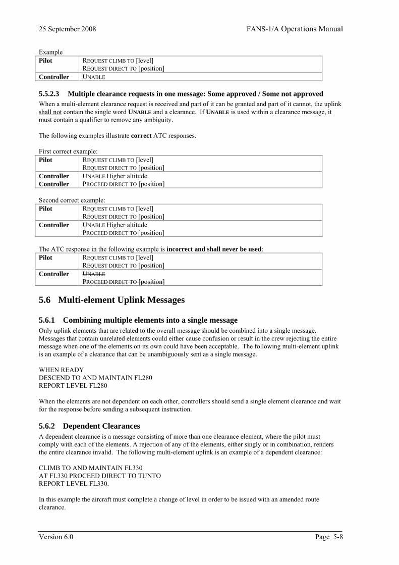
25 September 2008 FANS-1/A Operations Manual
Example Pilot REQUEST CLIMB TO [level]
REQUEST DIRECT TO [position] Controller UNABLE
5.5.2.3 Multiple clearance requests in one message: Some approved / Some not approved When a multi-element clearance request is received and part of it can be granted and part of it cannot, the uplink shall not contain the single word UNABLE and a clearance. If UNABLE is used within a clearance message, it must contain a qualifier to remove any ambiguity. The following examples illustrate correct ATC responses. First correct example: Pilot REQUEST CLIMB TO [level]
REQUEST DIRECT TO [position] Controller Controller
UNABLE Higher altitude PROCEED DIRECT TO [position]
Second correct example: Pilot REQUEST CLIMB TO [level]
REQUEST DIRECT TO [position] Controller UNABLE Higher altitude
PROCEED DIRECT TO [position] The ATC response in the following example is incorrect and shall never be used: Pilot REQUEST CLIMB TO [level]
REQUEST DIRECT TO [position] Controller UNABLE
PROCEED DIRECT TO [position]
5.6 Multi-element Uplink Messages
5.6.1 Combining multiple elements into a single message Only uplink elements that are related to the overall message should be combined into a single message. Messages that contain unrelated elements could either cause confusion or result in the crew rejecting the entire message when one of the elements on its own could have been acceptable. The following multi-element uplink is an example of a clearance that can be unambiguously sent as a single message. WHEN READY DESCEND TO AND MAINTAIN FL280 REPORT LEVEL FL280 When the elements are not dependent on each other, controllers should send a single element clearance and wait for the response before sending a subsequent instruction.
5.6.2 Dependent Clearances A dependent clearance is a message consisting of more than one clearance element, where the pilot must comply with each of the elements. A rejection of any of the elements, either singly or in combination, renders the entire clearance invalid. The following multi-element uplink is an example of a dependent clearance: CLIMB TO AND MAINTAIN FL330 AT FL330 PROCEED DIRECT TO TUNTO REPORT LEVEL FL330. In this example the aircraft must complete a change of level in order to be issued with an amended route clearance.
Version 6.0 Page 5-8
FANS-1/A Operations Manual 25 September 2008
Whenever possible, all elements of a dependent clearance should be sent in a single uplink message. Sending the elements as individual messages may compromise safety or separation if the pilot accepts the first uplink of a dependent clearance, complies with the instruction, and then responds UNABLE to the next message when received. By the time that the controller has received the UNABLE response, the aircraft could have begun executing the first instruction of a clearance that is invalid if the pilot cannot comply with the second element. The response to a multi-element uplink message will either be a WILCO or UNABLE that refers to the entire message. It is not possible for the pilot to respond to individual elements of a multi-element message. NOTE: Care must be taken in the construction of dependent clearances to ensure that there is no ambiguity present in the message. In the example above, the second element has been carefully chosen to reinforce the requirement instead of using the word THEN followed by the route clearance PROCEED DIRECT TO TUNTO. The following message is an example of poor message construction as it does not unambiguously convey to the pilot that the climb clearance must be completed prior to commencing the route clearance component. This format SHOULD NOT be used for dependent clearances: CLIMB TO AND MAINTAIN FL330 THEN PROCEED DIRECT TO TUNTO
5.7 Message Closure
5.7.1 General Definitions: • A message requiring a response remains open until a referenced response is received. • A message is closed when either a response is not technically required, or after a referenced response other
than STANDBY or REQUEST DEFERRED has been received. A normal downlink free text message (based on downlink message element DM#67) does not require a response from the controller to close the CPDLC exchange. However, a downlink free text message based on downlink message element DM#68 (Distress attribute) does require a response and the message will remain open until a referenced response is received. Any uplink message containing only free text requires a ROGER response. The message will remain open until a referenced response containing ROGER is received.
5.7.2 Answering an uplink free text When the controller sends a message containing only free text, or a free text element combined with elements that do not require a response, the pilot must respond to the free text with a ROGER response before responding to the actual contents of the message.
5.7.3 Dialogue commenced via CPDLC and continued via voice If a CPDLC message requiring a closure response is subsequently negotiated by voice, a CPDLC closure response message is still necessary to ensure the proper synchronization of ground and aircraft systems.
5.8 Position Reporting
5.8.1 General To harmonize waypoint position reports by either voice or data, the “Position” and “Next Position” shall only contain compulsory reporting points unless requested otherwise by ATC. The “Ensuing Significant Point” may
Page 5-9 Version 6.0
25 September 2008 FANS-1/A Operations Manual
be either the compulsory or non-compulsory reporting point after the “Next Position” (Refer AIREP form PANS/ATM, Appendix 1).
5.8.2 Downlink of position report When a CPDLC connection exists in a procedural, non-ADS-C environment, pilots shall ensure that position reporting is conducted via CPDLC. A CPDLC position report shall be sent manually by the pilot whenever an ATC waypoint is passed over, (or passed abeam when offset flight is in progress). ATC expects position reports based on downlink message DM#48 - POSITION REPORT.
5.8.3 Flexible track position reports All waypoints published for an independent flex track or user preferred route (UPR) are compulsory reporting points. However, when the track follows a published ATS route, position reports are not required at any non-compulsory waypoints defined for that ATS route.
5.8.4 First position report Pilots shall downlink a CPDLC position report (ATC waypoint) to the next ATSU after the completion of: • An initial CPDLC connection (when inbound from an area not providing CPDLC services), or during a
connection transfer; • Either when the CPDLC connection transfer has been completed; or at the associated FIR boundary. This position report is required whether or not there is an ADS-C contract in place. It serves as confirmation that the receiving centre is the Current Data Authority.
5.8.5 Sending of ATC waypoints only Additional non-ATC waypoints may be sequenced by the FMC, however information relating to these waypoints is not of interest to ATC. It is the pilot’s responsibility to report only at ATC waypoints.
5.8.6 Updating a waypoint estimate When it is necessary to update a waypoint ETA a free text message shall be sent in the form of – Revised ETA [position] [time].
5.8.7 Non-receipt of a scheduled position report If a scheduled position report is not received via CPDLC, the use of voice communication by the controller is not mandatory. The controller may obtain the report by uplinking message UM#147 - REQUEST POSITION REPORT.
5.8.8 Sequencing ‘ABEAM’ waypoints in excess of FMC parameters When an aircraft passes abeam a waypoint in excess of the defined sequencing parameter for the aircraft type the FMC will not sequence the active waypoint on the Legs and Position Report pages. Operators shall develop appropriate airborne procedures to ensure correct waypoint sequencing. Note: Some ATS systems use current GPS position that is included in the ATC position report to update their ground systems.
5.8.9 ARINC 424 fix names Crews should be aware that ATC ground systems can not process latitudes and longitudes encoded as fix names in the ARINC 424 format. Example 10N40 (indicates lat/long of 10N140W). Downlinks containing such fix names may be rejected by ATC systems.
5.9 FANS-1/A CPDLC Message Set and Intent This Section contains a complete listing of the message intent for all FANS-1/A CPDLC messages as defined by the OPLINK Panel. Additional comments provided by the ISPACG forum are displayed in Italics.
Version 6.0 Page 5-10

FANS-1/A Operations Manual 25 September 2008
5.9.1 Response Requirements Key: TYPE CLOSURE RESPONSES W/U WILCO, UNABLE, will close the uplink message. A/N AFFIRM, NEGATIVE, will close the uplink message.
R ROGER, will close the uplink message. Most messages with an NE attribute require an operational response. Only the correct operational response is presented to the pilot. The uplink message is considered to be closed on sending and does not require a response to close the dialogue. The WILCO, UNABLE, AFFIRM, NEGATIVE, ROGER, and STANDBY responses are not enabled for pilot selection.
NE
Y Response required. N Response not required
Note: Under some circumstances, an ERROR message will also close an uplink message. Multi element uplink messages require only a single closure response. The response required for a multi element message is the highest priority response out of each of the elements in the message. When determining the highest priority, the following priority order is used:
W/U A/N R NE
For example, the uplink CLIMB TO AND MAINTAIN FL370. REPORT LEVEL FL370 contains two elements. The first element requires a “W/U” response, the second an “R” response. The highest priority response is W/U, therefore this is the response required for closure.
5.9.2 Uplink - Responses and Acknowledgements UM
MESSAGE ELEMENT MESSAGE INTENT RESPONSE
0 UNABLE Indicates that ATS cannot comply with the request. NE
STANDBY
Indicates that ATS has received the message and will respond. The pilot is informed that the request is being assessed and there will be a short-term delay (within 10 minutes). The exchange is not closed and the request will be responded to when conditions allow. The intention of this message element is to provide advice to the flight crew that the requested clearance is being assessed, but is not immediately available (e.g. due to traffic, ATC coordination requirements etc). 6 It should not be used as a means of simply acknowledging that the downlink request has been received by the ATS ground system. 7
NE 1
REQUEST DEFERRE
D
Indicates that ATS has received the request but it has been deferred until later.The pilot is informed that the request is being assessed and a long-term delay can be expected. The exchange is not closed and the request will be responded to when conditions allow.
NE 2
3 ROGER Indicates that ATS has received and understood the message. NE 4 AFFIRM Yes NE 5 NEGATIVE No NE
5.9.3 Uplink - Vertical Clearances UM MESSAGE ELEMENT MESSAGE INTENT RESPONSE 6 EXPECT [altitude] Notification that a level change instruction
should be expected. R
Page 5-11 Version 6.0
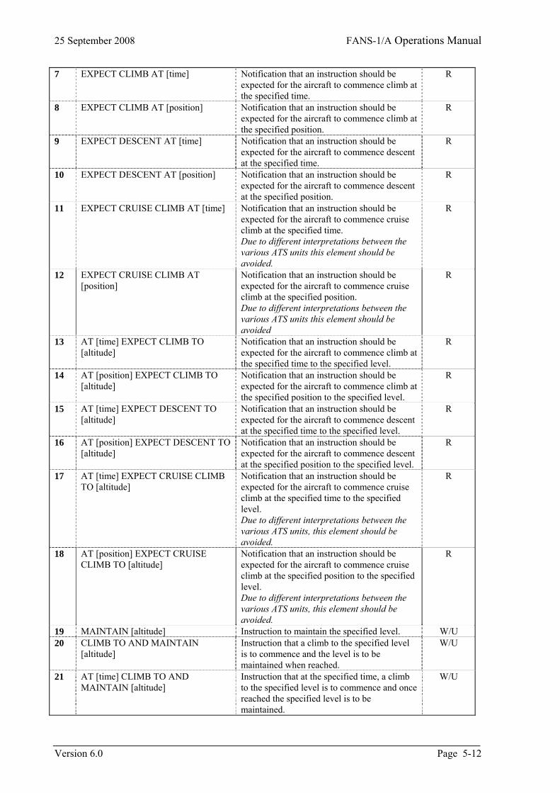
25 September 2008 FANS-1/A Operations Manual
7 EXPECT CLIMB AT [time] Notification that an instruction should be expected for the aircraft to commence climb at the specified time.
R
8 EXPECT CLIMB AT [position] Notification that an instruction should be expected for the aircraft to commence climb at the specified position.
R
9 EXPECT DESCENT AT [time] Notification that an instruction should be expected for the aircraft to commence descent at the specified time.
R
10 EXPECT DESCENT AT [position] Notification that an instruction should be expected for the aircraft to commence descent at the specified position.
R
11 EXPECT CRUISE CLIMB AT [time] Notification that an instruction should be expected for the aircraft to commence cruise climb at the specified time. Due to different interpretations between the various ATS units this element should be avoided.
R
12 EXPECT CRUISE CLIMB AT [position]
Notification that an instruction should be expected for the aircraft to commence cruise climb at the specified position. Due to different interpretations between the various ATS units this element should be avoided
R
13 AT [time] EXPECT CLIMB TO [altitude]
Notification that an instruction should be expected for the aircraft to commence climb at the specified time to the specified level.
R
14 AT [position] EXPECT CLIMB TO [altitude]
Notification that an instruction should be expected for the aircraft to commence climb at the specified position to the specified level.
R
15 AT [time] EXPECT DESCENT TO [altitude]
Notification that an instruction should be expected for the aircraft to commence descent at the specified time to the specified level.
R
16 AT [position] EXPECT DESCENT TO [altitude]
Notification that an instruction should be expected for the aircraft to commence descent at the specified position to the specified level.
R
17 AT [time] EXPECT CRUISE CLIMB TO [altitude]
Notification that an instruction should be expected for the aircraft to commence cruise climb at the specified time to the specified level. Due to different interpretations between the various ATS units, this element should be avoided.
R
18 AT [position] EXPECT CRUISE CLIMB TO [altitude]
Notification that an instruction should be expected for the aircraft to commence cruise climb at the specified position to the specified level. Due to different interpretations between the various ATS units, this element should be avoided.
R
19 MAINTAIN [altitude] Instruction to maintain the specified level. W/U 20 CLIMB TO AND MAINTAIN
[altitude] Instruction that a climb to the specified level is to commence and the level is to be maintained when reached.
W/U
21 AT [time] CLIMB TO AND MAINTAIN [altitude]
Instruction that at the specified time, a climb to the specified level is to commence and once reached the specified level is to be maintained.
W/U
Version 6.0 Page 5-12
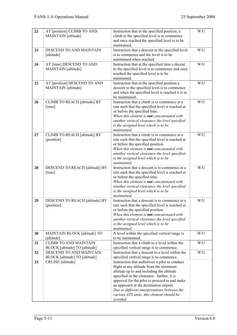
FANS-1/A Operations Manual 25 September 2008
22 AT [position] CLIMB TO AND MAINTAIN [altitude]
Instruction that at the specified position, a climb to the specified level is to commence and once reached the specified level is to be maintained.
W/U
23 DESCEND TO AND MAINTAIN [altitude]
Instruction that a descent to the specified level is to commence and the level is to be maintained when reached.
W/U
24 AT [time] DESCEND TO AND MAINTAIN [altitude]
Instruction that at the specified time a decent to the specified level is to commence and once reached the specified level is to be maintained.
W/U
25 AT [position] DESCEND TO AND MAINTAIN [altitude]
Instruction that at the specified position a descent to the specified level is to commence and when the specified level is reached it is to be maintained.
W/U
26 CLIMB TO REACH [altitude] BY [time]
Instruction that a climb is to commence at a rate such that the specified level is reached at or before the specified time. When this element is not concatenated with another vertical clearance the level specified is the assigned level which is to be maintained.
W/U
27 CLIMB TO REACH [altitude] BY [position]
Instruction that a climb is to commence at a rate such that the specified level is reached at or before the specified position. When this element is not concatenated with another vertical clearance the level specified is the assigned level which is to be maintained.
W/U
28 DESCEND TO REACH [altitude] BY [time]
Instruction that a descent is to commence at a rate such that the specified level is reached at or before the specified time. When this element is not concatenated with another vertical clearance the level specified is the assigned level which is to be maintained.
W/U
29 DESCEND TO REACH [altitude] BY [position]
Instruction that a descent is to commence at a rate such that the specified level is reached at or before the specified position. When this element is not concatenated with another vertical clearance the level specified is the assigned level which is to be maintained.
W/U
30 MAINTAIN BLOCK [altitude] TO [altitude]
A level within the specified vertical range is to be maintained.
W/U
31 CLIMB TO AND MAINTAIN BLOCK [altitude] TO [altitude]
Instruction that a climb to a level within the specified vertical range is to commence.
W/U
32 DESCEND TO AND MAINTAIN BLOCK [altitude] TO [altitude]
Instruction that a descent to a level within the specified vertical range is to commence.
W/U
33 CRUISE [altitude] Instruction that authorizes a pilot to conduct flight at any altitude from the minimum altitude up to and including the altitude specified in the clearance. further, it is approval for the pilot to proceed to and make an approach at the destination airport. Due to different interpretations between the various ATS units, this element should be avoided.
Page 5-13 Version 6.0
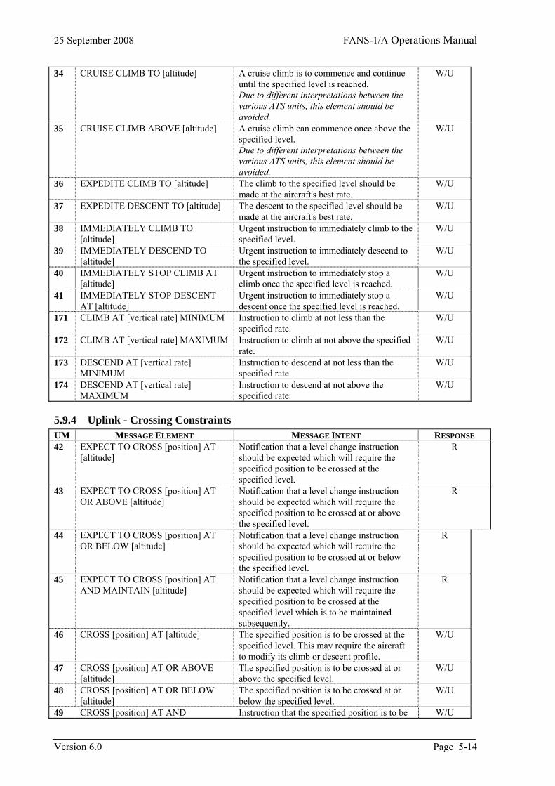
25 September 2008 FANS-1/A Operations Manual
34 CRUISE CLIMB TO [altitude] A cruise climb is to commence and continue until the specified level is reached. Due to different interpretations between the various ATS units, this element should be avoided.
W/U
35 CRUISE CLIMB ABOVE [altitude] A cruise climb can commence once above the specified level. Due to different interpretations between the various ATS units, this element should be avoided.
W/U
36 EXPEDITE CLIMB TO [altitude] The climb to the specified level should be made at the aircraft's best rate.
W/U
37 EXPEDITE DESCENT TO [altitude] The descent to the specified level should be made at the aircraft's best rate.
W/U
38 IMMEDIATELY CLIMB TO [altitude]
Urgent instruction to immediately climb to the specified level.
W/U
39 IMMEDIATELY DESCEND TO [altitude]
Urgent instruction to immediately descend to the specified level.
W/U
40 IMMEDIATELY STOP CLIMB AT [altitude]
Urgent instruction to immediately stop a climb once the specified level is reached.
W/U
41 IMMEDIATELY STOP DESCENT AT [altitude]
Urgent instruction to immediately stop a descent once the specified level is reached.
W/U
171 CLIMB AT [vertical rate] MINIMUM Instruction to climb at not less than the specified rate.
W/U
172 CLIMB AT [vertical rate] MAXIMUM Instruction to climb at not above the specified rate.
W/U
173 DESCEND AT [vertical rate] MINIMUM
Instruction to descend at not less than the specified rate.
W/U
174 DESCEND AT [vertical rate] MAXIMUM
Instruction to descend at not above the specified rate.
W/U
5.9.4 Uplink - Crossing Constraints UM MESSAGE ELEMENT MESSAGE INTENT RESPONSE 42 EXPECT TO CROSS [position] AT
[altitude] Notification that a level change instruction should be expected which will require the specified position to be crossed at the specified level.
R
43 EXPECT TO CROSS [position] AT OR ABOVE [altitude]
Notification that a level change instruction should be expected which will require the specified position to be crossed at or above the specified level.
R
44 EXPECT TO CROSS [position] AT OR BELOW [altitude]
Notification that a level change instruction should be expected which will require the specified position to be crossed at or below the specified level.
R
45 EXPECT TO CROSS [position] AT AND MAINTAIN [altitude]
Notification that a level change instruction should be expected which will require the specified position to be crossed at the specified level which is to be maintained subsequently.
R
46 CROSS [position] AT [altitude]
The specified position is to be crossed at the specified level. This may require the aircraft to modify its climb or descent profile.
W/U
47 CROSS [position] AT OR ABOVE [altitude]
The specified position is to be crossed at or above the specified level.
W/U
48 CROSS [position] AT OR BELOW [altitude]
The specified position is to be crossed at or below the specified level.
W/U
49 CROSS [position] AT AND Instruction that the specified position is to be W/U
Version 6.0 Page 5-14
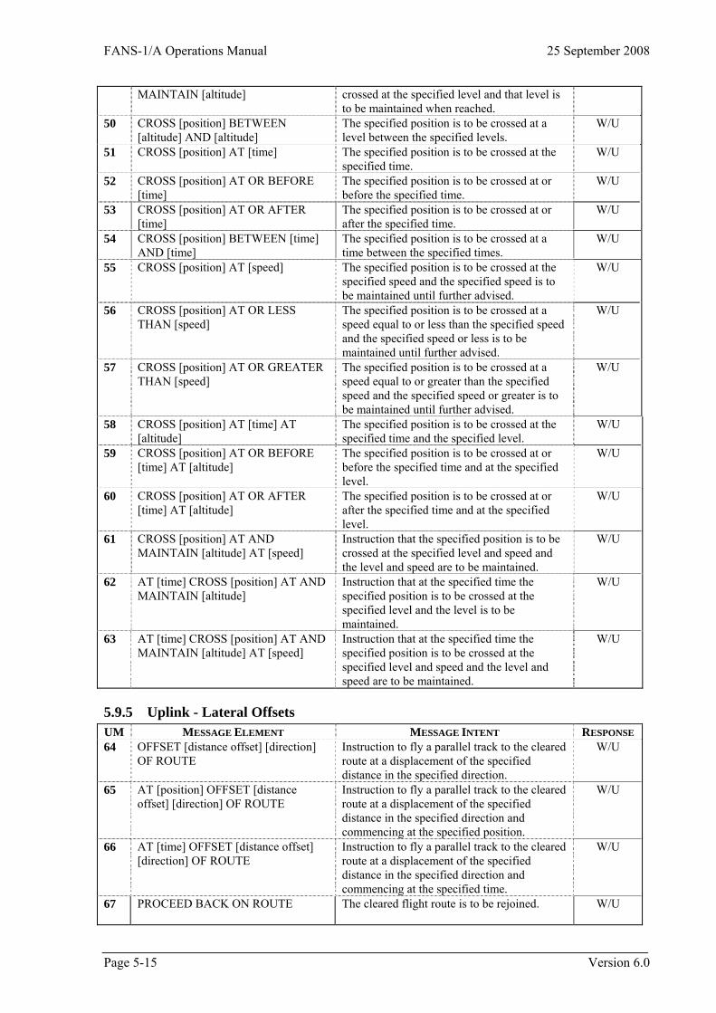
FANS-1/A Operations Manual 25 September 2008
MAINTAIN [altitude] crossed at the specified level and that level is to be maintained when reached.
50 CROSS [position] BETWEEN [altitude] AND [altitude]
The specified position is to be crossed at a level between the specified levels.
W/U
51 CROSS [position] AT [time] The specified position is to be crossed at the specified time.
W/U
52 CROSS [position] AT OR BEFORE [time]
The specified position is to be crossed at or before the specified time.
W/U
53 CROSS [position] AT OR AFTER [time]
The specified position is to be crossed at or after the specified time.
W/U
54 CROSS [position] BETWEEN [time] AND [time]
The specified position is to be crossed at a time between the specified times.
W/U
55 CROSS [position] AT [speed] The specified position is to be crossed at the specified speed and the specified speed is to be maintained until further advised.
W/U
56 CROSS [position] AT OR LESS THAN [speed]
The specified position is to be crossed at a speed equal to or less than the specified speed and the specified speed or less is to be maintained until further advised.
W/U
57 CROSS [position] AT OR GREATER THAN [speed]
The specified position is to be crossed at a speed equal to or greater than the specified speed and the specified speed or greater is to be maintained until further advised.
W/U
58 CROSS [position] AT [time] AT [altitude]
The specified position is to be crossed at the specified time and the specified level.
W/U
59 CROSS [position] AT OR BEFORE [time] AT [altitude]
The specified position is to be crossed at or before the specified time and at the specified level.
W/U
60 CROSS [position] AT OR AFTER [time] AT [altitude]
The specified position is to be crossed at or after the specified time and at the specified level.
W/U
61 CROSS [position] AT AND MAINTAIN [altitude] AT [speed]
Instruction that the specified position is to be crossed at the specified level and speed and the level and speed are to be maintained.
W/U
62 AT [time] CROSS [position] AT AND MAINTAIN [altitude]
Instruction that at the specified time the specified position is to be crossed at the specified level and the level is to be maintained.
W/U
63 AT [time] CROSS [position] AT AND MAINTAIN [altitude] AT [speed]
Instruction that at the specified time the specified position is to be crossed at the specified level and speed and the level and speed are to be maintained.
W/U
5.9.5 Uplink - Lateral Offsets UM MESSAGE ELEMENT MESSAGE INTENT RESPONSE 64 OFFSET [distance offset] [direction]
OF ROUTE
Instruction to fly a parallel track to the cleared route at a displacement of the specified distance in the specified direction.
W/U
65 AT [position] OFFSET [distance offset] [direction] OF ROUTE
Instruction to fly a parallel track to the cleared route at a displacement of the specified distance in the specified direction and commencing at the specified position.
W/U
66 AT [time] OFFSET [distance offset] [direction] OF ROUTE
Instruction to fly a parallel track to the cleared route at a displacement of the specified distance in the specified direction and commencing at the specified time.
W/U
67 PROCEED BACK ON ROUTE
The cleared flight route is to be rejoined. W/U
Page 5-15 Version 6.0
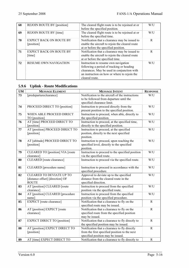
25 September 2008 FANS-1/A Operations Manual
68 REJOIN ROUTE BY [position] The cleared flight route is to be rejoined at or before the specified position.
W/U
69 REJOIN ROUTE BY [time] The cleared flight route is to be rejoined at or before the specified time.
W/U
70 EXPECT BACK ON ROUTE BY [position]
Notification that a clearance may be issued to enable the aircraft to rejoin the cleared route at or before the specified position.
R
71 EXPECT BACK ON ROUTE BY [time]
Notification that a clearance may be issued to enable the aircraft to rejoin the cleared route at or before the specified time.
R
72 RESUME OWN NAVIGATION Instruction to resume own navigation following a period of tracking or heading clearances. May be used in conjunction with an instruction on how or where to rejoin the cleared route.
W/U
5.9.6 Uplink - Route Modifications UM MESSAGE ELEMENT MESSAGE INTENT RESPONSE 73 [predepartureclearance]
Notification to the aircraft of the instructions to be followed from departure until the specified clearance limit.
W/U
74 PROCEED DIRECT TO [position] Instruction to proceed directly from the present position to the specified position.
W/U
75 WHEN ABLE PROCEED DIRECT TO [position]
Instruction to proceed, when able, directly to the specified position.
W/U
76 AT [time] PROCEED DIRECT TO [position]
Instruction to proceed, at the specified time, directly to the specified position.
W/U
77 AT [position] PROCEED DIRECT TO [position]
lnstruction to proceed, at the specified position, directly to the next specified position.
W/U
78 AT [altitude] PROCEED DIRECT TO [position]
Instruction to proceed, upon reaching the specified level, directly to the specified position.
W/U
79 CLEARED TO [position] VIA [route clearance]
Instruction to proceed to the specified position via the specified route.
W/U
80 CLEARED [route clearance] Instruction to proceed via the specified route.
W/U
81 CLEARED [procedure name] Instruction to proceed in accordance with the specified procedure.
W/U
82 CLEARED TO DEVIATE UP TO [distance offset] [direction] OF ROUTE
Approval to deviate up to the specified distance from the cleared route in the specified direction.
W/U
83 AT [position] CLEARED [route clearance]
Instruction to proceed from the specified position via the specified route.
W/U
84 AT [position] CLEARED [procedure name]
Instruction to proceed from the specified position via the specified procedure.
W/U
85 EXPECT [route clearance] Notification that a clearance to fly on the specified route may be issued.
R
86 AT [position] EXPECT [route clearance]
Notification that a clearance to fly on the specified route from the specified position may be issued.
R
87 EXPECT DIRECT TO [position] Notification that a clearance to fly directly to the specified position may be issued.
R
88 AT [position] EXPECT DIRECT TO [position]
Notification that a clearance to fly directly from the first specified position to the next specified position may be issued.
R
89 AT [time] EXPECT DIRECT TO Notification that a clearance to fly directly to R
Version 6.0 Page 5-16
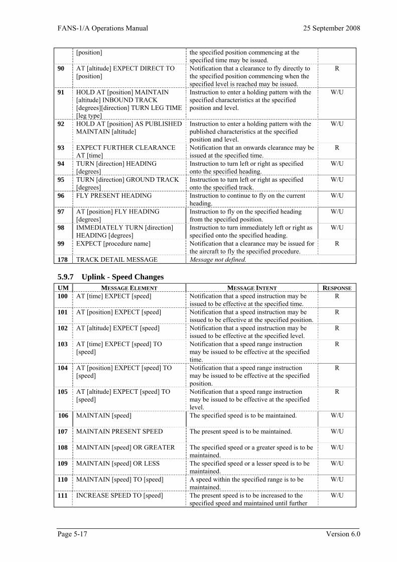
FANS-1/A Operations Manual 25 September 2008
[position] the specified position commencing at the specified time may be issued.
90 AT [altitude] EXPECT DIRECT TO [position]
Notification that a clearance to fly directly to the specified position commencing when the specified level is reached may be issued.
R
91 HOLD AT [position] MAINTAIN [altitude] INBOUND TRACK [degrees][direction] TURN LEG TIME [leg type]
Instruction to enter a holding pattern with the specified characteristics at the specified position and level.
W/U
92 HOLD AT [position] AS PUBLISHED MAINTAIN [altitude]
Instruction to enter a holding pattern with the published characteristics at the specified position and level.
W/U
93 EXPECT FURTHER CLEARANCE AT [time]
Notification that an onwards clearance may be issued at the specified time.
R
94 TURN [direction] HEADING [degrees]
Instruction to turn left or right as specified onto the specified heading.
W/U
95 TURN [direction] GROUND TRACK [degrees]
Instruction to turn left or right as specified onto the specified track.
W/U
96 FLY PRESENT HEADING
Instruction to continue to fly on the current heading.
W/U
97 AT [position] FLY HEADING [degrees]
Instruction to fly on the specified heading from the specified position.
W/U
98 IMMEDIATELY TURN [direction] HEADING [degrees]
Instruction to turn immediately left or right as specified onto the specified heading.
W/U
99 EXPECT [procedure name] Notification that a clearance may be issued for the aircraft to fly the specified procedure.
R
TRACK DETAIL MESSAGE Message not defined. 178
5.9.7 Uplink - Speed Changes UM MESSAGE ELEMENT MESSAGE INTENT RESPONSE 100 AT [time] EXPECT [speed] Notification that a speed instruction may be
issued to be effective at the specified time. R
101 AT [position] EXPECT [speed] Notification that a speed instruction may be issued to be effective at the specified position.
R
102 AT [altitude] EXPECT [speed]
Notification that a speed instruction may be issued to be effective at the specified level.
R
103 AT [time] EXPECT [speed] TO [speed]
Notification that a speed range instruction may be issued to be effective at the specified time.
R
104 AT [position] EXPECT [speed] TO [speed]
Notification that a speed range instruction may be issued to be effective at the specified position.
R
105 AT [altitude] EXPECT [speed] TO [speed]
Notification that a speed range instruction may be issued to be effective at the specified level.
R
106 MAINTAIN [speed]
The specified speed is to be maintained. W/U
107 MAINTAIN PRESENT SPEED
The present speed is to be maintained. W/U
108 MAINTAIN [speed] OR GREATER The specified speed or a greater speed is to be maintained.
W/U
109 MAINTAIN [speed] OR LESS The specified speed or a lesser speed is to be maintained.
W/U
110 MAINTAIN [speed] TO [speed] A speed within the specified range is to be maintained.
W/U
111 INCREASE SPEED TO [speed] The present speed is to be increased to the specified speed and maintained until further
W/U
Page 5-17 Version 6.0
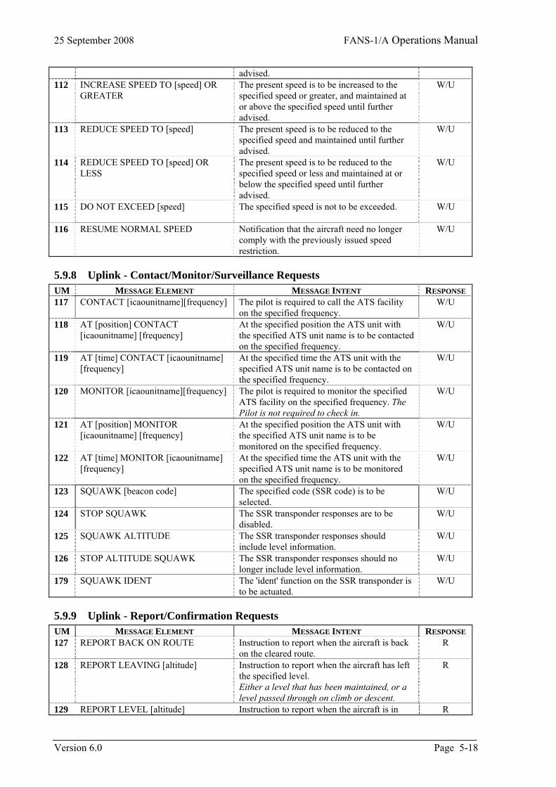
25 September 2008 FANS-1/A Operations Manual
advised. 112 INCREASE SPEED TO [speed] OR
GREATER The present speed is to be increased to the specified speed or greater, and maintained at or above the specified speed until further advised.
W/U
113 REDUCE SPEED TO [speed] The present speed is to be reduced to the specified speed and maintained until further advised.
W/U
114 REDUCE SPEED TO [speed] OR LESS
The present speed is to be reduced to the specified speed or less and maintained at or below the specified speed until further advised.
W/U
115 DO NOT EXCEED [speed]
The specified speed is not to be exceeded. W/U
116 RESUME NORMAL SPEED Notification that the aircraft need no longer comply with the previously issued speed restriction.
W/U
5.9.8 Uplink - Contact/Monitor/Surveillance Requests UM MESSAGE ELEMENT MESSAGE INTENT RESPONSE 117 CONTACT [icaounitname][frequency]
The pilot is required to call the ATS facility on the specified frequency.
W/U
118 AT [position] CONTACT [icaounitname] [frequency]
At the specified position the ATS unit with the specified ATS unit name is to be contacted on the specified frequency.
W/U
119 AT [time] CONTACT [icaounitname] [frequency]
At the specified time the ATS unit with the specified ATS unit name is to be contacted on the specified frequency.
W/U
120 MONITOR [icaounitname][frequency]
The pilot is required to monitor the specified ATS facility on the specified frequency. The Pilot is not required to check in.
W/U
121 AT [position] MONITOR [icaounitname] [frequency]
At the specified position the ATS unit with the specified ATS unit name is to be monitored on the specified frequency.
W/U
122 AT [time] MONITOR [icaounitname] [frequency]
At the specified time the ATS unit with the specified ATS unit name is to be monitored on the specified frequency.
W/U
123 SQUAWK [beacon code]
The specified code (SSR code) is to be selected.
W/U
124 STOP SQUAWK The SSR transponder responses are to be disabled.
W/U
125 SQUAWK ALTITUDE
The SSR transponder responses should include level information.
W/U
126 STOP ALTITUDE SQUAWK
The SSR transponder responses should no longer include level information.
W/U
179 SQUAWK IDENT The 'ident' function on the SSR transponder is to be actuated.
W/U
5.9.9 Uplink - Report/Confirmation Requests UM MESSAGE ELEMENT MESSAGE INTENT RESPONSE 127 REPORT BACK ON ROUTE Instruction to report when the aircraft is back
on the cleared route. R
128 REPORT LEAVING [altitude]
Instruction to report when the aircraft has left the specified level. Either a level that has been maintained, or a level passed through on climb or descent.
R
129 REPORT LEVEL [altitude] Instruction to report when the aircraft is in R
Version 6.0 Page 5-18
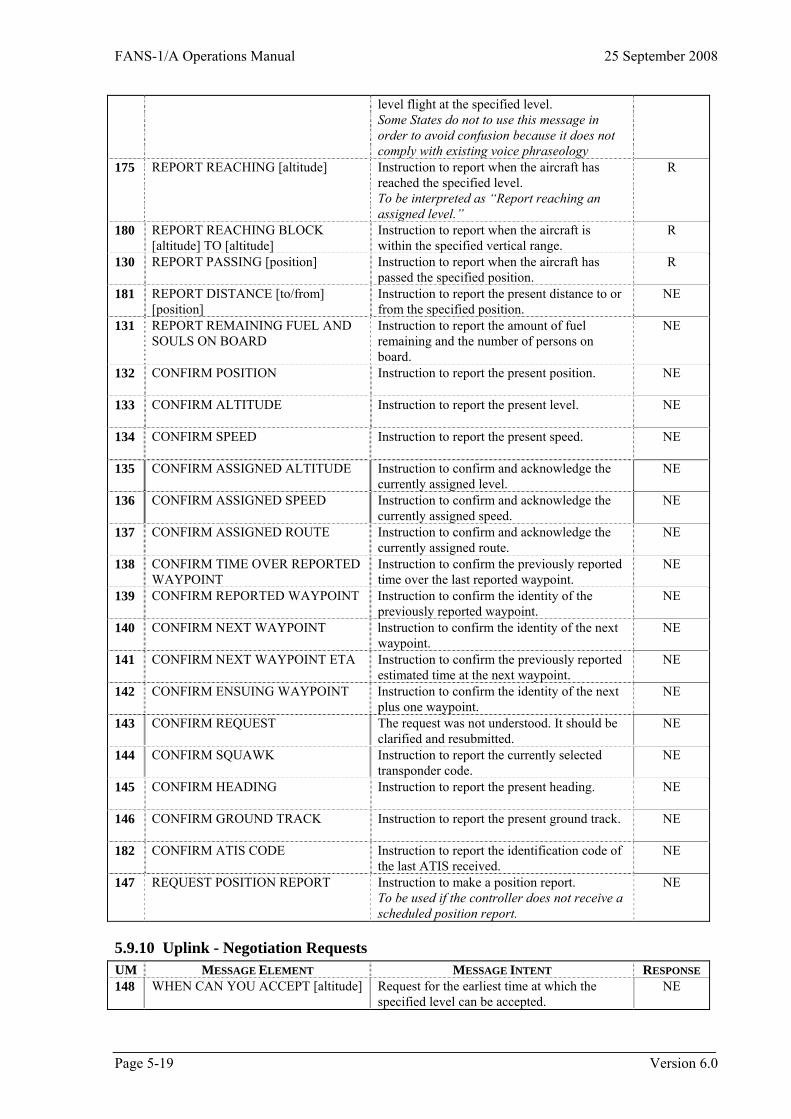
FANS-1/A Operations Manual 25 September 2008
level flight at the specified level. Some States do not to use this message in order to avoid confusion because it does not comply with existing voice phraseology
175 REPORT REACHING [altitude]
Instruction to report when the aircraft has reached the specified level. To be interpreted as “Report reaching an assigned level.”
R
180 REPORT REACHING BLOCK [altitude] TO [altitude]
Instruction to report when the aircraft is within the specified vertical range.
R
130 REPORT PASSING [position] Instruction to report when the aircraft has passed the specified position.
R
181 REPORT DISTANCE [to/from] [position]
Instruction to report the present distance to or from the specified position.
NE
131 REPORT REMAINING FUEL AND SOULS ON BOARD
Instruction to report the amount of fuel remaining and the number of persons on board.
NE
132 CONFIRM POSITION
Instruction to report the present position. NE
133 CONFIRM ALTITUDE
Instruction to report the present level. NE
134 CONFIRM SPEED
Instruction to report the present speed. NE
135 CONFIRM ASSIGNED ALTITUDE
Instruction to confirm and acknowledge the currently assigned level.
NE
136 CONFIRM ASSIGNED SPEED Instruction to confirm and acknowledge the currently assigned speed.
NE
137 CONFIRM ASSIGNED ROUTE Instruction to confirm and acknowledge the currently assigned route.
NE
138 CONFIRM TIME OVER REPORTED WAYPOINT
Instruction to confirm the previously reported time over the last reported waypoint.
NE
139 CONFIRM REPORTED WAYPOINT Instruction to confirm the identity of the previously reported waypoint.
NE
140 CONFIRM NEXT WAYPOINT lnstruction to confirm the identity of the next waypoint.
NE
141 CONFIRM NEXT WAYPOINT ETA Instruction to confirm the previously reported estimated time at the next waypoint.
NE
142 CONFIRM ENSUING WAYPOINT Instruction to confirm the identity of the next plus one waypoint.
NE
143 CONFIRM REQUEST The request was not understood. It should be clarified and resubmitted.
NE
144 CONFIRM SQUAWK Instruction to report the currently selected transponder code.
NE
145 CONFIRM HEADING
Instruction to report the present heading. NE
146 CONFIRM GROUND TRACK
Instruction to report the present ground track. NE
182 CONFIRM ATIS CODE Instruction to report the identification code of the last ATIS received.
NE
147 REQUEST POSITION REPORT
Instruction to make a position report. To be used if the controller does not receive a scheduled position report.
NE
5.9.10 Uplink - Negotiation Requests UM MESSAGE ELEMENT MESSAGE INTENT RESPONSE 148 WHEN CAN YOU ACCEPT [altitude]
Request for the earliest time at which the specified level can be accepted.
NE
Page 5-19 Version 6.0
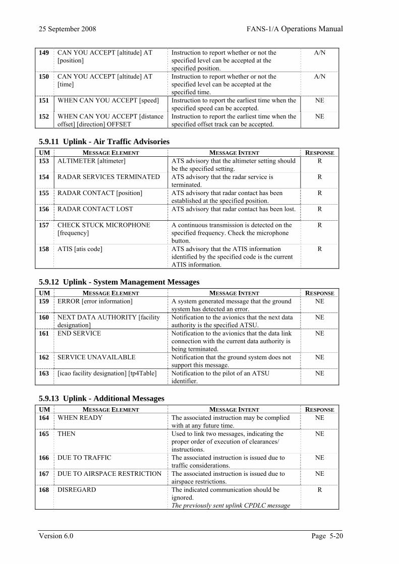
25 September 2008 FANS-1/A Operations Manual
149 CAN YOU ACCEPT [altitude] AT [position]
Instruction to report whether or not the specified level can be accepted at the specified position.
A/N
150 CAN YOU ACCEPT [altitude] AT [time]
Instruction to report whether or not the specified level can be accepted at the specified time.
A/N
151 WHEN CAN YOU ACCEPT [speed] Instruction to report the earliest time when the specified speed can be accepted.
NE
152 WHEN CAN YOU ACCEPT [distance offset] [direction] OFFSET
Instruction to report the earliest time when the specified offset track can be accepted.
NE
5.9.11 Uplink - Air Traffic Advisories UM MESSAGE ELEMENT MESSAGE INTENT RESPONSE 153 ALTIMETER [altimeter] ATS advisory that the altimeter setting should
be the specified setting. R
154 RADAR SERVICES TERMINATED
ATS advisory that the radar service is terminated.
R
155 RADAR CONTACT [position] ATS advisory that radar contact has been established at the specified position.
R
156 RADAR CONTACT LOST ATS advisory that radar contact has been lost.
R
157 CHECK STUCK MICROPHONE [frequency]
A continuous transmission is detected on the specified frequency. Check the microphone button.
R
158 ATIS [atis code] ATS advisory that the ATIS information identified by the specified code is the current ATIS information.
R
5.9.12 Uplink - System Management Messages UM MESSAGE ELEMENT MESSAGE INTENT RESPONSE 159 ERROR [error information] A system generated message that the ground
system has detected an error. NE
160 NEXT DATA AUTHORITY [facility designation]
Notification to the avionics that the next data authority is the specified ATSU.
NE
161 END SERVICE Notification to the avionics that the data link connection with the current data authority is being terminated.
NE
162 SERVICE UNAVAILABLE Notification that the ground system does not support this message.
NE
163 [icao facility designation] [tp4Table]
Notification to the pilot of an ATSU identifier.
NE
5.9.13 Uplink - Additional Messages UM MESSAGE ELEMENT MESSAGE INTENT RESPONSE 164 WHEN READY The associated instruction may be complied
with at any future time. NE
165 THEN Used to link two messages, indicating the proper order of execution of clearances/ instructions.
NE
166 DUE TO TRAFFIC
The associated instruction is issued due to traffic considerations.
NE
167 DUE TO AIRSPACE RESTRICTION The associated instruction is issued due to airspace restrictions.
NE
168 DISREGARD The indicated communication should be ignored. The previously sent uplink CPDLC message
R
Version 6.0 Page 5-20
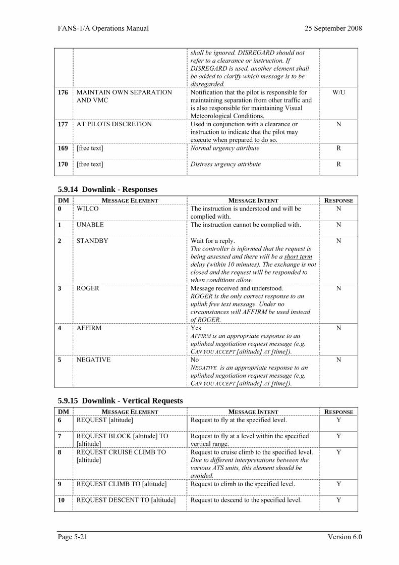
FANS-1/A Operations Manual 25 September 2008
shall be ignored. DISREGARD should not refer to a clearance or instruction. If DISREGARD is used, another element shall be added to clarify which message is to be disregarded.
176 MAINTAIN OWN SEPARATION AND VMC
Notification that the pilot is responsible for maintaining separation from other traffic and is also responsible for maintaining Visual Meteorological Conditions.
W/U
177 AT PILOTS DISCRETION Used in conjunction with a clearance or instruction to indicate that the pilot may execute when prepared to do so.
N
[free text]
Normal urgency attribute R 169
[free text]
Distress urgency attribute R 170
5.9.14 Downlink - Responses DM MESSAGE ELEMENT MESSAGE INTENT RESPONSE 0 WILCO
The instruction is understood and will be complied with.
N
1 UNABLE The instruction cannot be complied with.
N
2 STANDBY
Wait for a reply. The controller is informed that the request is being assessed and there will be a short term delay (within 10 minutes). The exchange is not closed and the request will be responded to when conditions allow.
N
3 ROGER
Message received and understood. ROGER is the only correct response to an uplink free text message. Under no circumstances will AFFIRM be used instead of ROGER.
N
AFFIRM
Yes AFFIRM is an appropriate response to an uplinked negotiation request message (e.g. CAN YOU ACCEPT [altitude] AT [time]).
N 4
NEGATIVE
No NEGATIVE is an appropriate response to an uplinked negotiation request message (e.g. CAN YOU ACCEPT [altitude] AT [time]).
N 5
5.9.15 Downlink - Vertical Requests DM MESSAGE ELEMENT MESSAGE INTENT RESPONSE 6 REQUEST [altitude]
Request to fly at the specified level. Y
7 REQUEST BLOCK [altitude] TO [altitude]
Request to fly at a level within the specified vertical range.
Y
8 REQUEST CRUISE CLIMB TO [altitude]
Request to cruise climb to the specified level. Due to different interpretations between the various ATS units, this element should be avoided.
Y
9 REQUEST CLIMB TO [altitude]
Request to climb to the specified level. Y
10 REQUEST DESCENT TO [altitude]
Request to descend to the specified level. Y
Page 5-21 Version 6.0
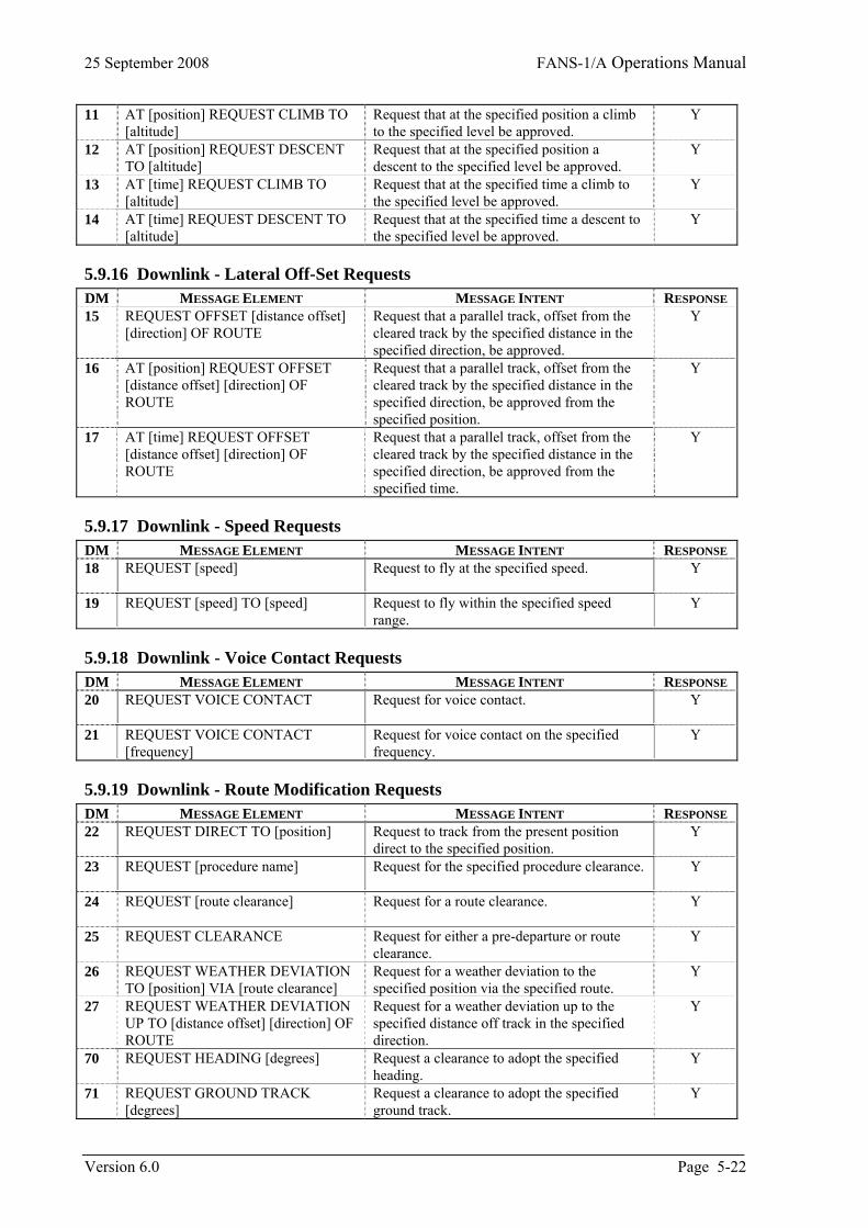
25 September 2008 FANS-1/A Operations Manual
11 AT [position] REQUEST CLIMB TO [altitude]
Request that at the specified position a climb to the specified level be approved.
Y
12 AT [position] REQUEST DESCENT TO [altitude]
Request that at the specified position a descent to the specified level be approved.
Y
13 AT [time] REQUEST CLIMB TO [altitude]
Request that at the specified time a climb to the specified level be approved.
Y
14 AT [time] REQUEST DESCENT TO [altitude]
Request that at the specified time a descent to the specified level be approved.
Y
5.9.16 Downlink - Lateral Off-Set Requests DM MESSAGE ELEMENT MESSAGE INTENT RESPONSE 15 REQUEST OFFSET [distance offset]
[direction] OF ROUTE
Request that a parallel track, offset from the cleared track by the specified distance in the specified direction, be approved.
Y
16 AT [position] REQUEST OFFSET [distance offset] [direction] OF ROUTE
Request that a parallel track, offset from the cleared track by the specified distance in the specified direction, be approved from the specified position.
Y
17 AT [time] REQUEST OFFSET [distance offset] [direction] OF ROUTE
Request that a parallel track, offset from the cleared track by the specified distance in the specified direction, be approved from the specified time.
Y
5.9.17 Downlink - Speed Requests DM MESSAGE ELEMENT MESSAGE INTENT RESPONSE 18 REQUEST [speed]
Request to fly at the specified speed. Y
19 REQUEST [speed] TO [speed] Request to fly within the specified speed range.
Y
5.9.18 Downlink - Voice Contact Requests DM MESSAGE ELEMENT MESSAGE INTENT RESPONSE 20 REQUEST VOICE CONTACT
Request for voice contact. Y
21 REQUEST VOICE CONTACT [frequency]
Request for voice contact on the specified frequency.
Y
5.9.19 Downlink - Route Modification Requests DM MESSAGE ELEMENT MESSAGE INTENT RESPONSE 22 REQUEST DIRECT TO [position] Request to track from the present position
direct to the specified position. Y
23 REQUEST [procedure name]
Request for the specified procedure clearance. Y
24 REQUEST [route clearance]
Request for a route clearance. Y
25 REQUEST CLEARANCE
Request for either a pre-departure or route clearance.
Y
26 REQUEST WEATHER DEVIATION TO [position] VIA [route clearance]
Request for a weather deviation to the specified position via the specified route.
Y
27 REQUEST WEATHER DEVIATION UP TO [distance offset] [direction] OF ROUTE
Request for a weather deviation up to the specified distance off track in the specified direction.
Y
70 REQUEST HEADING [degrees] Request a clearance to adopt the specified heading.
Y
71 REQUEST GROUND TRACK [degrees]
Request a clearance to adopt the specified ground track.
Y
Version 6.0 Page 5-22
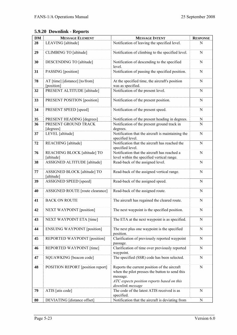
FANS-1/A Operations Manual 25 September 2008
5.9.20 Downlink - Reports DM MESSAGE ELEMENT MESSAGE INTENT RESPONSE 28 LEAVING [altitude]
Notification of leaving the specified level. N
29 CLIMBING TO [altitude]
Notification of climbing to the specified level. N
30 DESCENDING TO [altitude]
Notification of descending to the specified level.
N
31 PASSING [position] Notification of passing the specified position.
N
78 AT [time] [distance] [to/from] [position]
At the specified time, the aircraft's position was as specified.
N
32 PRESENT ALTITUDE [altitude]
Notification of the present level. N
33 PRESENT POSITION [position]
Notification of the present position. N
34 PRESENT SPEED [speed]
Notification of the present speed. N
35 PRESENT HEADING [degrees] Notification of the present heading in degrees. N 36 PRESENT GROUND TRACK
[degrees] Notification of the present ground track in degrees.
N
37 LEVEL [altitude]
Notification that the aircraft is maintaining the specified level.
N
72 REACHING [altitude]
Notification that the aircraft has reached the specified level.
N
76 REACHING BLOCK [altitude] TO [altitude]
Notification that the aircraft has reached a level within the specified vertical range.
N
38 ASSIGNED ALTITUDE [altitude]
Read-back of the assigned level. N
77 ASSIGNED BLOCK [altitude] TO [altitude]
Read-back of the assigned vertical range. N
39 ASSIGNED SPEED [speed]
Read-back of the assigned speed. N
40 ASSIGNED ROUTE [route clearance]
Read-back of the assigned route. N
41 BACK ON ROUTE The aircraft has regained the cleared route.
N
42 NEXT WAYPOINT [position] The next waypoint is the specified position.
N
43 NEXT WAYPOINT ETA [time] The ETA at the next waypoint is as specified.
N
44 ENSUING WAYPOINT [position] The next plus one waypoint is the specified position.
N
45 REPORTED WAYPOINT [position] Clarification of previously reported waypoint passage.
N
46 REPORTED WAYPOINT [time] Clarification of time over previously reported waypoint.
N
47 SQUAWKING [beacon code]
The specified (SSR) code has been selected. N
48 POSITION REPORT [position report]
Reports the current position of the aircraft when the pilot presses the button to send this message. ATC expects position reports based on this downlink message
N
79 ATIS [atis code] The code of the latest ATIS received is as specified.
N
80 DEVIATING [distance offset] Notification that the aircraft is deviating from N
Page 5-23 Version 6.0
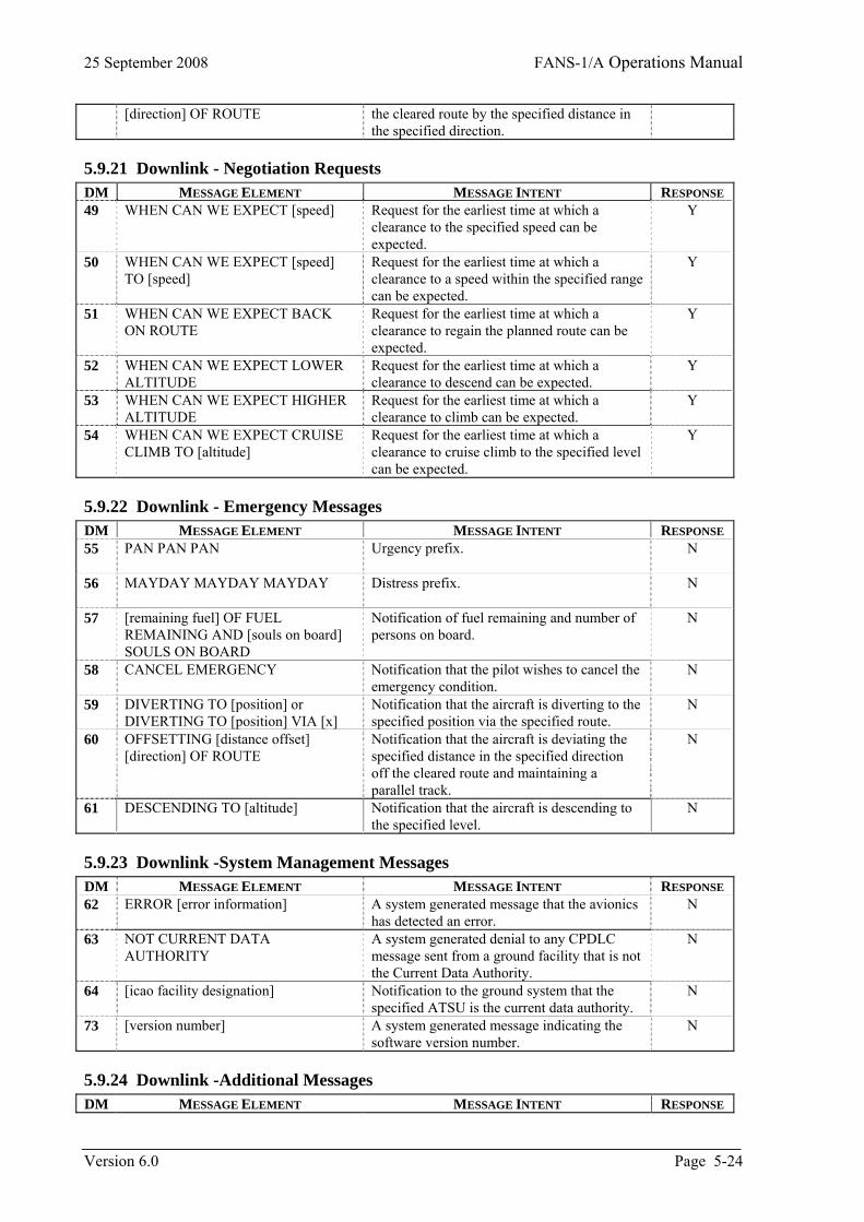
25 September 2008 FANS-1/A Operations Manual
[direction] OF ROUTE
the cleared route by the specified distance in the specified direction.
5.9.21 Downlink - Negotiation Requests DM MESSAGE ELEMENT MESSAGE INTENT RESPONSE 49 WHEN CAN WE EXPECT [speed] Request for the earliest time at which a
clearance to the specified speed can be expected.
Y
50 WHEN CAN WE EXPECT [speed] TO [speed]
Request for the earliest time at which a clearance to a speed within the specified range can be expected.
Y
51 WHEN CAN WE EXPECT BACK ON ROUTE
Request for the earliest time at which a clearance to regain the planned route can be expected.
Y
52 WHEN CAN WE EXPECT LOWER ALTITUDE
Request for the earliest time at which a clearance to descend can be expected.
Y
53 WHEN CAN WE EXPECT HIGHER ALTITUDE
Request for the earliest time at which a clearance to climb can be expected.
Y
54 WHEN CAN WE EXPECT CRUISE CLIMB TO [altitude]
Request for the earliest time at which a clearance to cruise climb to the specified level can be expected.
Y
5.9.22 Downlink - Emergency Messages DM MESSAGE ELEMENT MESSAGE INTENT RESPONSE 55 PAN PAN PAN
Urgency prefix. N
56 MAYDAY MAYDAY MAYDAY
Distress prefix. N
57 [remaining fuel] OF FUEL REMAINING AND [souls on board] SOULS ON BOARD
Notification of fuel remaining and number of persons on board.
N
58 CANCEL EMERGENCY Notification that the pilot wishes to cancel the emergency condition.
N
59 DIVERTING TO [position] or DIVERTING TO [position] VIA [x]
Notification that the aircraft is diverting to the specified position via the specified route.
N
60 OFFSETTING [distance offset] [direction] OF ROUTE
Notification that the aircraft is deviating the specified distance in the specified direction off the cleared route and maintaining a parallel track.
N
61 DESCENDING TO [altitude]
Notification that the aircraft is descending to the specified level.
N
5.9.23 Downlink -System Management Messages DM MESSAGE ELEMENT MESSAGE INTENT RESPONSE 62 ERROR [error information] A system generated message that the avionics
has detected an error. N
63 NOT CURRENT DATA AUTHORITY
A system generated denial to any CPDLC message sent from a ground facility that is not the Current Data Authority.
N
64 [icao facility designation]
Notification to the ground system that the specified ATSU is the current data authority.
N
73 [version number] A system generated message indicating the software version number.
N
5.9.24 Downlink -Additional Messages DM MESSAGE ELEMENT MESSAGE INTENT RESPONSE
Version 6.0 Page 5-24
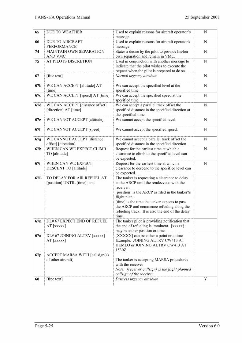
FANS-1/A Operations Manual 25 September 2008
65 DUE TO WEATHER Used to explain reasons for aircraft operator’s message.
N
66 DUE TO AIRCRAFT PERFORMANCE
Used to explain reasons for aircraft operator's message.
N
74 MAINTAIN OWN SEPARATION AND VMC
States a desire by the pilot to provide his/her own separation and remain in VMC.
N
75 AT PILOTS DISCRETION Used in conjunction with another message to indicate that the pilot wishes to execute the request when the pilot is prepared to do so.
N
[free text]
Normal urgency attribute N 67
67b WE CAN ACCEPT [altitude] AT [time]
We can accept the specified level at the specified time.
N
67c WE CAN ACCEPT [speed] AT [time]
We can accept the specified speed at the specified time.
N
67d WE CAN ACCEPT [distance offset] [direction] AT [time]
We can accept a parallel track offset the specified distance in the specified direction at the specified time.
N
67e WE CANNOT ACCEPT [altitude]
We cannot accept the specified level. N
67f WE CANNOT ACCEPT [speed]
We cannot accept the specified speed. N
67g WE CANNOT ACCEPT [distance offset] [direction]
We cannot accept a parallel track offset the specified distance in the specified direction.
N
67h WHEN CAN WE EXPECT CLIMB TO [altitude]
Request for the earliest time at which a clearance to climb to the specified level can be expected.
N
67i WHEN CAN WE EXPECT DESCENT TO [altitude]
Request for the earliest time at which a clearance to descend to the specified level can be expected.
N
67L TO DELAY FOR AIR REFUEL AT [position] UNTIL [time]; and
The tanker is requesting a clearance to delay at the ARCP until the rendezvous with the receiver. [position] is the ARCP as filed in the tanker?s flight plan. [time] is the time the tanker expects to pass the ARCP and commence refueling along the refueling track. It is also the end of the delay time.
67n DL# 67 EXPECT END OF REFUEL AT [xxxxx]�
The tanker pilot is providing notification that the end of refueling is imminent. [xxxxx} may be either position or time.�
67o DL# 67 JOINING ALTRV [xxxxx] AT [xxxxx]
[XXXXX] can be either a point or a time Example: JOINING ALTRV CW413 AT HEMLO or JOINING ALTRV CW413 AT 1530Z�
67p ACCEPT MARSA WITH [callsign(s) of other aircraft]
The tanker is accepting MARSA procedures with the receiver Note: [receiver callsign] is the flight planned callsign of the receiver
68 [free text]
Distress urgency attribute Y
Page 5-25 Version 6.0
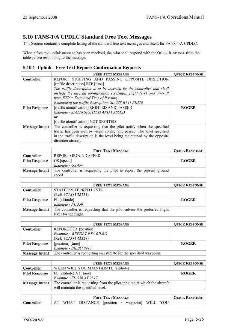
25 September 2008 FANS-1/A Operations Manual
5.10 FANS-1/A CPDLC Standard Free Text Messages This Section contains a complete listing of the standard free text messages and intent for FANS-1/A CPDLC. When a free text uplink message has been received, the pilot shall respond with the QUICK RESPONSE from the table before responding to the message.
5.10.1 Uplink - Free Text Report/ Confirmation Requests FREE TEXT MESSAGE QUICK RESPONSE Controller REPORT SIGHTING AND PASSING OPPOSITE DIRECTION
[traffic description] ETP [time] The traffic description is to be inserted by the controller and shall include the aircraft identification (callsign), flight level and aircraft type. ETP = Estimated Time of Passing. Example of the traffic description: SIA228 B747 FL370
Pilot Response [traffic identification] SIGHTED AND PASSED Example - SIA228 SIGHTED AND PASSED or [traffic identification] NOT SIGHTED
ROGER
Message Intent The controller is requesting that the pilot notify when the specified traffic has been seen by visual contact and passed. The level specified in the traffic description is the level being maintained by the opposite direction aircraft.
FREE TEXT MESSAGE QUICK RESPONSE Controller REPORT GROUND SPEED Pilot Response GS [speed]
Example - GS 490 ROGER
Message Intent The controller is requesting the pilot to report the present ground
speed.
FREE TEXT MESSAGE QUICK RESPONSE Controller STATE PREFERRED LEVEL
(Ref: ICAO UM231)
Pilot Response FL [altitude] Example - FL 350
ROGER
Message Intent The controller is requesting that the pilot advise the preferred flight level for the flight.
FREE TEXT MESSAGE QUICK RESPONSE Controller REPORT ETA [position]
Example – REPORT ETA BILBO (Ref: ICAO UM228)
Pilot Response [position] [time] Example - BILBO 0413
ROGER
Message Intent The controller is requesting an estimate for the specified waypoint. FREE TEXT MESSAGE QUICK RESPONSE Controller WHEN WILL YOU MAINTAIN FL [altitude] Pilot Response FL [altitude] AT [time]
Example - FL 350 AT 2317 ROGER
Message Intent The controller is requesting from the pilot the time at which the aircraft will maintain the specified level.
FREE TEXT MESSAGE QUICK RESPONSE Controller AT WHAT DISTANCE [position / waypoint] WILL YOU
Version 6.0 Page 5-26
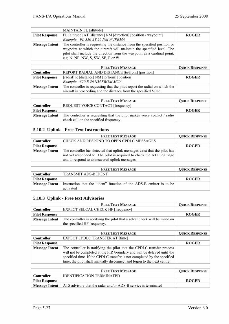
FANS-1/A Operations Manual 25 September 2008
MAINTAIN FL [altitude] Pilot Response FL [altitude] AT [distance] NM [direction] [position / waypoint]
Example - FL 350 AT 26 NM W IPEMA ROGER
Message Intent The controller is requesting the distance from the specified position or waypoint at which the aircraft will maintain the specified level. The pilot shall include the direction from the waypoint as a cardinal point, e.g. N, NE, NW, S, SW, SE, E or W.
FREE TEXT MESSAGE QUICK RESPONSE Controller REPORT RADIAL AND DISTANCE [to/from] [position] Pilot Response [radial] R [distance] NM [to/from] [position]
Example - 320 R 26 NM FROM MCY ROGER
Message Intent The controller is requesting that the pilot report the radial on which the
aircraft is proceeding and the distance from the specified VOR.
FREE TEXT MESSAGE QUICK RESPONSE Controller REQUEST VOICE CONTACT [frequency] Pilot Response ROGER Message Intent The controller is requesting that the pilot makes voice contact / radio
check call on the specified frequency.
5.10.2 Uplink - Free Text Instructions FREE TEXT MESSAGE QUICK RESPONSE Controller CHECK AND RESPOND TO OPEN CPDLC MESSAGES Pilot Response ROGER Message Intent The controller has detected that uplink messages exist that the pilot has
not yet responded to. The pilot is required to check the ATC log page and to respond to unanswered uplink messages.
FREE TEXT MESSAGE QUICK RESPONSE Controller TRANSMIT ADS-B IDENT Pilot Response ROGER Message Intent Instruction that the “ident” function of the ADS-B emitter is to be
activated
5.10.3 Uplink - Free text Advisories FREE TEXT MESSAGE QUICK RESPONSE Controller EXPECT SELCAL CHECK HF [frequency] Pilot Response ROGER Message Intent The controller is notifying the pilot that a selcal check will be made on
the specified HF frequency.
FREE TEXT MESSAGE QUICK RESPONSE Controller EXPECT CPDLC TRANSFER AT [time] Pilot Response ROGER Message Intent The controller is notifying the pilot that the CPDLC transfer process
will not be completed at the FIR boundary and will be delayed until the specified time. If the CPDLC transfer is not completed by the specified time, the pilot shall manually disconnect and logon to the next centre.
FREE TEXT MESSAGE QUICK RESPONSE Controller IDENTIFICATION TERMINATED Pilot Response ROGER Message Intent ATS advisory that the radar and/or ADS-B service is terminated
Page 5-27 Version 6.0
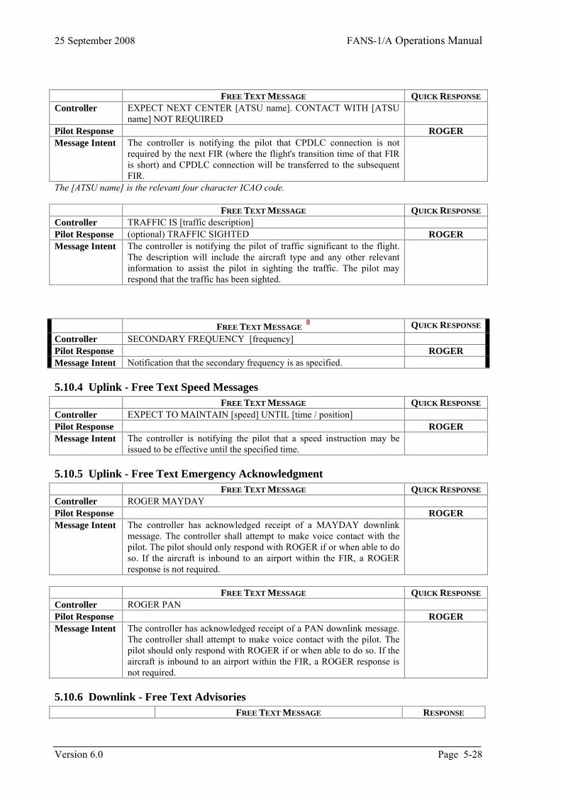
25 September 2008 FANS-1/A Operations Manual
Version 6.0 Page 5-28
FREE TEXT MESSAGE QUICK RESPONSE Controller EXPECT NEXT CENTER [ATSU name]. CONTACT WITH [ATSU
name] NOT REQUIRED
Pilot Response ROGER Message Intent The controller is notifying the pilot that CPDLC connection is not
required by the next FIR (where the flight's transition time of that FIR is short) and CPDLC connection will be transferred to the subsequent FIR.
The [ATSU name] is the relevant four character ICAO code. FREE TEXT MESSAGE QUICK RESPONSE Controller TRAFFIC IS [traffic description] Pilot Response (optional) TRAFFIC SIGHTED ROGER Message Intent The controller is notifying the pilot of traffic significant to the flight.
The description will include the aircraft type and any other relevant information to assist the pilot in sighting the traffic. The pilot may respond that the traffic has been sighted.
FREE TEXT MESSAGE
8
QUICK RESPONSE
Controller SECONDARY FREQUENCY [frequency] Pilot Response ROGER Message Intent Notification that the secondary frequency is as specified.
5.10.4 Uplink - Free Text Speed Messages FREE TEXT MESSAGE QUICK RESPONSE Controller EXPECT TO MAINTAIN [speed] UNTIL [time / position] Pilot Response ROGER Message Intent The controller is notifying the pilot that a speed instruction may be
issued to be effective until the specified time.
5.10.5 Uplink - Free Text Emergency Acknowledgment FREE TEXT MESSAGE QUICK RESPONSE Controller ROGER MAYDAY Pilot Response ROGER Message Intent The controller has acknowledged receipt of a MAYDAY downlink
message. The controller shall attempt to make voice contact with the pilot. The pilot should only respond with ROGER if or when able to do so. If the aircraft is inbound to an airport within the FIR, a ROGER response is not required.
FREE TEXT MESSAGE QUICK RESPONSE Controller ROGER PAN Pilot Response ROGER Message Intent The controller has acknowledged receipt of a PAN downlink message.
The controller shall attempt to make voice contact with the pilot. The pilot should only respond with ROGER if or when able to do so. If the aircraft is inbound to an airport within the FIR, a ROGER response is not required.
5.10.6 Downlink - Free Text Advisories FREE TEXT MESSAGE RESPONSE
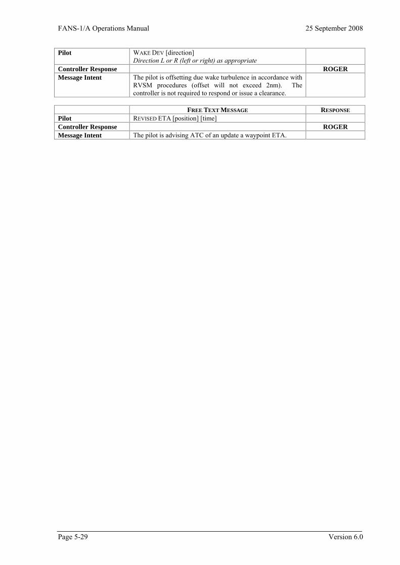
FANS-1/A Operations Manual 25 September 2008
Page 5-29 Version 6.0
Pilot WAKE DEV [direction] Direction L or R (left or right) as appropriate
Controller Response ROGER Message Intent The pilot is offsetting due wake turbulence in accordance with
RVSM procedures (offset will not exceed 2nm). The controller is not required to respond or issue a clearance.
FREE TEXT MESSAGE RESPONSE Pilot REVISED ETA [position] [time] Controller Response ROGER Message Intent The pilot is advising ATC of an update a waypoint ETA.

FANS-1/A Operations Manual 25 September 2008
6 ADS-C Procedures
6.1 Introduction In the CNS/ATM environment, surveillance may be provided by Automatic Dependent Surveillance (ADS). ADS-C allows the establishment of communication contracts between ground systems and an aircraft's avionics system. An ADS-C contract contains the ATC data requirements for ADS reporting as well as frequency of the ADS reports. The implementation of ADS-C provides surveillance capability in oceanic and en-route continental airspace and is intended to replace CPDLC and verbal position reporting in areas where non-radar separation is currently applied. In non-radar airspace, the effective use of ADS-C in the provision of air traffic services enhances flight safety, facilitates the reduction of separation minima and better accommodates user-preferred flight profiles.
6.2 ADS-C Description Three types of ADS-C contracts can be established with an aircraft. Each of these contracts operates independently from the others. These contracts are the: • Periodic; • Event; and • Demand. The establishment of ADS-C contracts is initiated by the ground system and does not require pilot action providing that the airborne system is armed. The pilot has the ability to cancel all contracts by selecting ADS off.
6.2.1 The periodic contract The periodic contract allows an ATSU to specify the reporting frequency, to request that optional data groups be added to the basic ADS-C report, and to specify the frequency at which the optional groups are to be included in the reports. The periodic reporting rate can generally be altered by the controller to allow for situations where a higher or lower reporting rate may be required. Only one periodic contract can be established between a ground system and a particular aircraft at any one time. Whenever a new periodic contract is established, the previous periodic contract is replaced. The periodic contract will remain in effect until it is modified or cancelled.
6.2.2 The event contract An event contract specifies a request for reports to be transmitted by the aircraft whenever a defined “event” occurs. Only one event contract can be established between a ground system and a particular aircraft at any one time, however the event contract can contain multiple event types. Note that multiple ATSUs with ADS-C connections can each establish their own event contracts with an aircraft. Once an event contract has been established, it remains in effect until the specific event requests are fulfilled, or it is cancelled by the ground system. The Vertical Rate Change Event is triggered when the aircraft’s vertical rate is either less than or greater than a parameter defined in the contract. The Lateral Deviation Change Event is triggered when the aircraft’s actual position exceeds a lateral distance parameter from the aircraft’s expected position on the active flight plan.
Page 6-1 Version 6.0
25 September 2008 FANS-1/A Operations Manual
The Altitude Range Change Event is triggered when the aircraft’s altitude exceeds the altitude ceiling or floor defined in the contract by the ground system. Once a vertical rate change, lateral deviation change, or altitude range event trigger has occurred, a recurrence of this event no longer triggers an event report. The ground system must initiate a new event contract every time that one of these specific events occurs. The Waypoint Change Event is triggered by a change to the next or the next-plus-one waypoints. Such a change normally occurs due to routine waypoint sequencing. However, it will also be triggered by occurrences such as a change to a non-ATS waypoint entered by the pilot for operational reasons, or execution of a new route affecting the next or next-plus-one waypoints. Unlike the other event contracts, the waypoint change event trigger remains in effect for all waypoint changes.
6.2.3 The demand contract The demand contract is a “one-off” request from the ground system for the FMS to provide an ADS report containing specific data as defined in the request. A demand contract can be requested by the ground system at any time. The demand contract request will not affect any existing contracts.
6.2.4 Emergency mode The emergency mode can only be activated by the pilot and is normally cancelled by the pilot. While it is possible for some ground systems to cancel the emergency mode status, most ground systems do not have this capability although some ground systems can control the “display” of the emergency mode status to the controller. The pilot normally activates the ADS emergency mode automatically by sending a CPDLC MAYDAY message, although the ADS emergency mode can also be set independently. When the ADS emergency mode is set, the aircraft immediately sends an ADS report containing an emergency flag that is interpreted by all ground systems that currently have periodic or event contracts established with that aircraft. The aircraft does not automatically send an ADS report at the time that the emergency mode is set. When the pilot cancels the emergency mode, the aircraft will send an emergency mode cancellation message to each ground station receiving the emergency mode reports with the next periodic report, whenever it may be due. The cancellation message will remove the emergency flag from the periodic contract, but the data contents will remain the same as per the emergency contract. Any previously existing data groups requested by the ground system will not be restored unless the ground system re-negotiates the periodic contract following receipt of the emergency cancellation message. Existing event contracts are unaffected by the emergency cancellation. Note: the Boeing B717 and B737 models will send the ADS emergency cancellation message immediately after being selected by the pilot.
6.3 Factors To Be Considered When Using ADS-C
6.3.1 Vertical and lateral variations Where the Altitude Range Change Event and Lateral Deviation Event contracts are established, the controller will only be alerted to vertical or lateral variations that exceed the associated tolerances. Note: If a regular periodic report is sent as the aircraft is deviating from cleared level or route (but still within the level or lateral tolerances) the controller will still be alerted to the variation despite no event report having been sent.
6.3.2 Figure of Merit data in ADS-C reports ADS-C reports contain FMS information relating to the Figure of Merit, ACAS/TCAS and the aircraft's navigational redundancy. Some automated ground systems use the FOM value received in an ADS-C report to determine whether to display the report to controllers, or to display a "high" or "low" quality ADS symbol.
Version 6.0 Page 6-2
FANS-1/A Operations Manual 25 September 2008
FOM data is not required for the use of current separation standards. However, where the separation standard being applied requires specific navigational accuracy, such as RNP, controllers shall rely on pilot advice as to the extent of any navigational degradation and shall adjust separation accordingly.
6.3.3 Flight crew modification of active route The flight crew will often insert non-ATS waypoints into the active flight plan in the FMS for flight system monitoring, or will modify the active route for planning purposes. Once the change is activated, a Waypoint Change Event report may be triggered. If so, non-ATS waypoints included in the active flight plan will be reflected in the Predicted Route Group, as well as the Intermediate and Fixed Projected Intent Groups, which may result in the next, or the next-plus-one waypoints from the report not being waypoints expected in the ATS flight plan or flight data record.
6.4 ADS-C Connection Management
6.4.1 Priority for the ADS-C connection FANS-1/A equipped aircraft can have up to five ADS-C connections. One of the five connections is reserved for use by the AOC. The aircraft has the capacity to report to four different ATSUs simultaneously using ADS. The FANS-1/A system does not assign any technical priority to ADS-C connections; therefore the controlling ATSU may not be aware of other connections established with the aircraft. As a result, a procedural hierarchy controlled by the Address Forwarding process (FN_CAD message) has been established.
6.4.1.1 Allocation of ADS-C connections Using the Address Forwarding process, the current controlling authority shall allocate ADS-C connection priority to the next ATSU that will have air traffic control responsibility for the aircraft. The priority for the allocation of ADS-C connections shall be in accordance with the following list: 1. The Current Data Authority, 2. The Next Data Authority, 3. An ATSU requiring a connection for monitoring operations close to a boundary, 4. Airline AOC 5. Other miscellaneous connections.
6.4.2 Near boundary ADS-C connections
6.4.2.1 Monitoring of an aircraft operating close to an airspace boundary When an aircraft will operate within the defined coordination parameter of the boundary with an adjacent ADS-C capable FIR, controllers shall determine during coordination whether that ATSU requires an ADS-C contract to monitor the aircraft’s progress near the boundary.
Page 6-3 Version 6.0
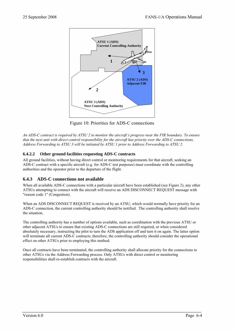
25 September 2008 FANS-1/A Operations Manual
ATSU 2 (ADS)Adjacent FIR
ATSU 3 (ADS)Next Controlling Authority
ATSU 1 (ADS)Current Controlling Authority
1
2
3
Figure 10: Priorities for ADS-C connections An ADS-C contract is required by ATSU 2 to monitor the aircraft’s progress near the FIR boundary. To ensure that the next unit with direct control responsibility for the aircraft has priority over the ADS-C connections, Address Forwarding to ATSU 3 will be initiated by ATSU 1 prior to Address Forwarding to ATSU 2.
6.4.2.2 Other ground facilities requesting ADS-C contracts All ground facilities, without having direct control or monitoring requirements for that aircraft, seeking an ADS-C contract with a specific aircraft (e.g. for ADS-C test purposes) must coordinate with the controlling authorities and the operator prior to the departure of the flight.
6.4.3 ADS-C connections not available When all available ADS-C connections with a particular aircraft have been established (see Figure 2), any other ATSUs attempting to connect with the aircraft will receive an ADS DISCONNECT REQUEST message with "reason code 1" (Congestion). When an ADS DISCONNECT REQUEST is received by an ATSU, which would normally have priority for an ADS-C connection, the current controlling authority should be notified. The controlling authority shall resolve the situation. The controlling authority has a number of options available, such as coordination with the previous ATSU or other adjacent ATSUs to ensure that existing ADS-C connections are still required, or when considered absolutely necessary, instructing the pilot to turn the ADS application off and turn it on again. The latter option will terminate all current ADS-C contracts; therefore, the controlling authority should consider the operational effect on other ATSUs prior to employing this method. Once all contracts have been terminated, the controlling authority shall allocate priority for the connections to other ATSUs via the Address Forwarding process. Only ATSUs with direct control or monitoring responsibilities shall re-establish contracts with the aircraft.
Version 6.0 Page 6-4
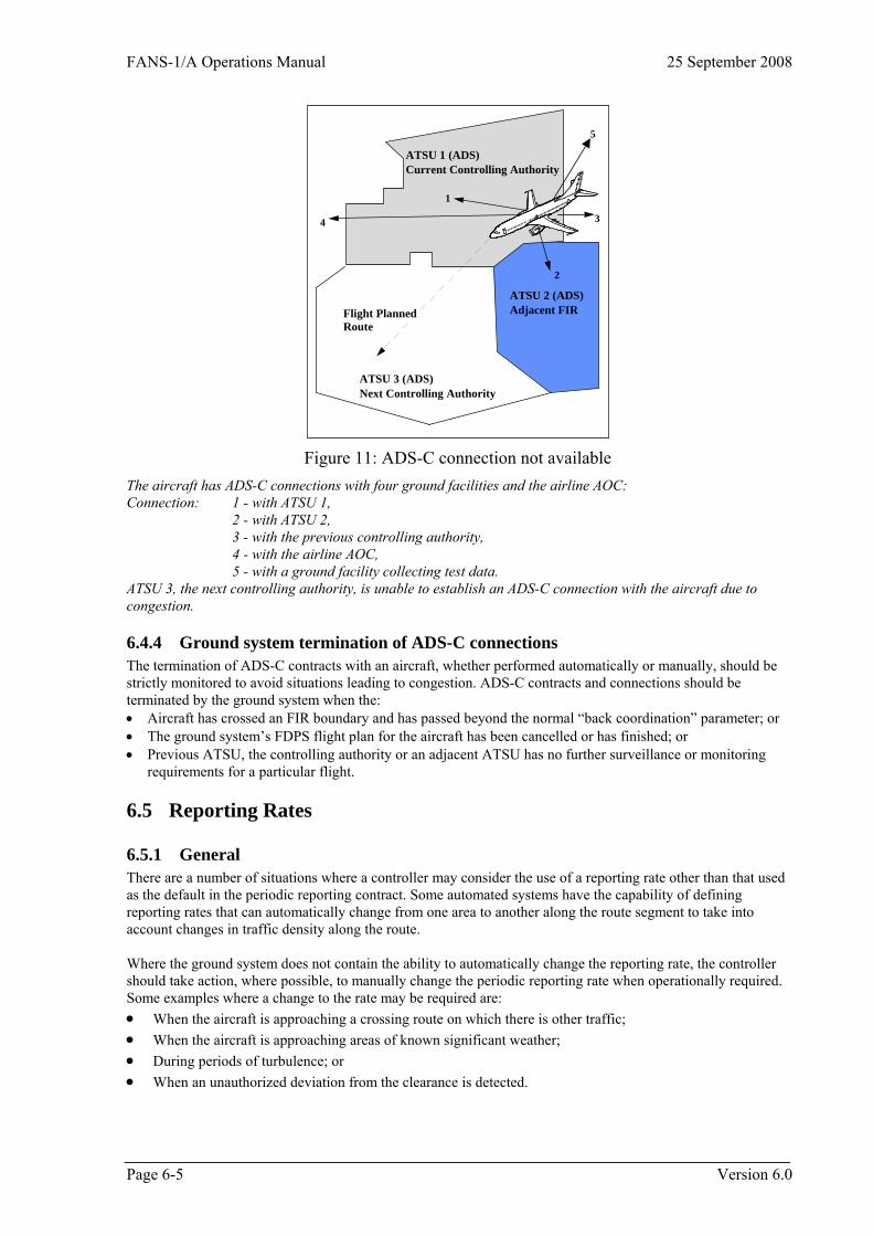
FANS-1/A Operations Manual 25 September 2008
ATSU 2 (ADS)Adjacent FIR
ATSU 3 (ADS)Next Controlling Authority
ATSU 1 (ADS)Current Controlling Authority
4
2
1
3
Flight PlannedRoute
5
Figure 11: ADS-C connection not available The aircraft has ADS-C connections with four ground facilities and the airline AOC: Connection: 1 - with ATSU 1, 2 - with ATSU 2, 3 - with the previous controlling authority, 4 - with the airline AOC,
5 - with a ground facility collecting test data. ATSU 3, the next controlling authority, is unable to establish an ADS-C connection with the aircraft due to congestion.
6.4.4 Ground system termination of ADS-C connections The termination of ADS-C contracts with an aircraft, whether performed automatically or manually, should be strictly monitored to avoid situations leading to congestion. ADS-C contracts and connections should be terminated by the ground system when the: • Aircraft has crossed an FIR boundary and has passed beyond the normal “back coordination” parameter; or • The ground system’s FDPS flight plan for the aircraft has been cancelled or has finished; or • Previous ATSU, the controlling authority or an adjacent ATSU has no further surveillance or monitoring
requirements for a particular flight.
6.5 Reporting Rates
6.5.1 General There are a number of situations where a controller may consider the use of a reporting rate other than that used as the default in the periodic reporting contract. Some automated systems have the capability of defining reporting rates that can automatically change from one area to another along the route segment to take into account changes in traffic density along the route. Where the ground system does not contain the ability to automatically change the reporting rate, the controller should take action, where possible, to manually change the periodic reporting rate when operationally required. Some examples where a change to the rate may be required are: • When the aircraft is approaching a crossing route on which there is other traffic; • When the aircraft is approaching areas of known significant weather; • During periods of turbulence; or • When an unauthorized deviation from the clearance is detected.
Page 6-5 Version 6.0

25 September 2008 FANS-1/A Operations Manual
6.5.2 Appropriate reporting rates ATSUs should ensure that the periodic reporting rate in use is in accordance with the position reporting requirements of the separation standards being used. When not required for the application of separation, or other factors, ATSUs should consider using less frequent periodic reporting rates for individual aircraft to reduce overall costs to the system.
6.5.3 Avoid high periodic reporting rates Arbitrarily selecting high periodic reporting rates adds undue economic costs and unnecessarily loads the data link system.
6.5.4 Other factors to be considered Depending on individual circumstances the controlling authority should limit the periodic reporting rate to not more frequently than five (5) minutes. Adjacent ATSUs with ADS-C contracts established with the same aircraft should restrict the periodic reporting rate to not more frequently than 15 minutes unless coordination is performed with the controlling authority and the controlling authority agrees to reduce any relatively high reporting rate currently in effect.
6.5.5 Default periodic reporting rates When setting a default periodic reporting rate, ATSUs should take into account factors such as conformance with ATC clearance requirements, traffic levels, alerting service requirements, and separation standard requirements.
6.6 Separation ADS-C may be used for the application of procedural separation within a mixed surveillance environment, such as airspace where position reports are provided by a mixture of ADS-C, CPDLC and voice. For example, ADS-C may be used to determine separation between two or more aircraft reporting by ADS-C, between ADS-C and non-ADS aircraft, between ADS-C aircraft and an aircraft identified on radar, and to ensure separation between ADS-C aircraft and special use airspace, such as military restricted areas.
6.6.1 Appropriate ADS-C reporting requirements When position reporting is being provided via ADS-C, to ensure that estimates being used for the application of separation are accurate ATSUs should establish appropriate: • ADS-C contracts; and • Periodic reporting frequencies.
6.6.2 Appropriate separation standard A separation standard to be applied in a mixed surveillance environment must be appropriate to the communications and navigational capability of the relevant aircraft. In the case of separation being applied between ADS-C and non-ADS aircraft, the separation standard must be appropriate to the capabilities of the non-ADS aircraft.
6.6.3 Vertical separation
6.6.3.1 Vertical tolerance consistency Where practical, the tolerances used to determine whether a specific level is occupied by an ADS-C reporting aircraft within the airspace of a specific ATSU should be consistent with other tolerances used throughout the airspace. For example, the vertical tolerances for ADS-C should be consistent with vertical tolerances used for level adherence monitoring by other forms of surveillance, such as radar.
6.6.3.2 Application of vertical tolerances Where other vertical tolerances do not exist, the vertical tolerances to be applied for ADS-C shall be (±) 300 feet. However, an individual ATSU may specify in local instructions and the AIP that a tolerance of not less than (±) 200 feet will be used to provide consistency with other vertical tolerances applied within the FIR.
Version 6.0 Page 6-6
FANS-1/A Operations Manual 25 September 2008
6.6.3.3 ADS-C level information does not satisfy vertical tolerance If displayed ADS-C level information does not satisfy the required tolerance for an individual ATSU then the pilot shall be advised accordingly and requested to confirm the aircraft's level. If following confirmation of the level the displayed ADS-C level information is still beyond the required tolerance, another method of separation or another method of determining level information may need to be applied.
6.6.3.4 Use of ADS-C level information When displayed ADS-C level information is within the specified tolerance of the expected or cleared flight level, the ADS-C level information may be used for the application of vertical separation, and to determine that an aircraft has reached or is maintaining a specified level.
6.6.3.5 Passing or leaving a level An aircraft can be considered to have left a specified level when the displayed ADS-C level information indicates that the aircraft has passed the level in the required direction by more than the required tolerance.
6.6.4 Longitudinal separation
6.6.4.1 Limitations on the use of tools ATSUs that use approved or integrated measurement tools for the purpose of determining screen-based separation should publish in local documentation any limitations on the use of such tools for the establishment and monitoring of separation standards.
6.6.4.2 Establishing longitudinal separation ADS-C reports may be used to establish and monitor longitudinal time and distance separation standards.
6.6.4.3 Using extrapolated or interpolated positions Some ground systems display an extrapolated or interpolated ADS symbol between the receipt of ADS-C reports. Providing that the periodic reporting rate in use is in accordance with any reporting rate required by the separation standard, separation may be determined between the extrapolated/interpolated symbols by the use of screen-based measurement tools, or by the use of automated conflict detection tools.
6.6.4.4 Validity of displayed information When extrapolated or interpolated ADS symbols are being used to provide separation and any doubt exists as to the integrity or validity of the information being presented, the controller shall send a Demand Contract Request to update the relevant information. If doubt still exists, the controller should consider the use of an alternative method of separation.
6.6.4.5 Time-based separation Ground system flight data records updated by ADS-C reports may be used in the application of appropriate time-based separation standards. Methods of determination may include reference to: • Estimates at actual waypoints; • Calculated estimates for positions not contained in the ATS flight plan; • Screen-based measurement tools; or • Automated conflict detection tools.
6.6.4.6 .Distance-based separation ADS-C reports may be used for the application of appropriate longitudinal distance standards. Methods of determination may include: • The use of automated system tools to measure the displayed positions of two or more aircraft reporting by
ADS-C; • Comparing the displayed position of an ADS-C aircraft with the position of another aircraft determined by
an alternative form of surveillance; or • The use of automated conflict detection tools.
Page 6-7 Version 6.0
25 September 2008 FANS-1/A Operations Manual
6.6.5 Lateral separation
6.6.5.1 Areas of lateral conflict ADS-C reports can be used to determine whether an aircraft is within or beyond an area of lateral conflict. Where lateral conflict calculations are not made by automated conflict detection tools, an ADS-C report observed outside an area of lateral conflict displayed or calculated on the screen is confirmation that the aircraft is outside the area of conflict.
6.7 Air Traffic Clearance Monitoring ADS-C reports can be used to monitor conformance with air traffic clearances.
6.7.1 Deviations from ATC clearances The pilot of an ADS aircraft observed to deviate significantly from its cleared flight profile shall be advised accordingly. The controller shall also take action as appropriate if such deviation is likely to affect the air traffic service being provided.
6.8 Coordination
6.8.1 Duty of care responsibility As airlines bear the cost of datalink communications, ATSUs should be aware of Duty of Care responsibility issues when ADS and other technologies allow the surveillance of aircraft and the possible detection of conflicts inside another ATSU's airspace. Local ATS instructions and/or Letters of Agreement between units should detail the coordination response required from one ATSU in the case of a suspected conflict being detected in the adjacent ATSU's airspace. Unless required for safety purposes, ATSUs should ensure that ADS-C is only enabled for aircraft inside their Area of Interest.
6.8.2 Coordinated data inconsistent with ADS displayed data The transferring controller shall advise during coordination if the aircraft is currently at a level or on a route different from that intended for the boundary crossing. When the coordination information relating to the transfer of control is different from the displayed ADS information and the required advice has not been provided, the receiving controller shall confirm the coordinated information with the transferring controller.
6.9 Alerting service For ADS-equipped aircraft, the provision of the alerting service should be based on the scheduled position reports provided by the periodic reporting contract.
6.9.1 Late or missing ADS-C Reports Whenever an ADS-C report (either a periodic or waypoint report) is not received within a parameter of the expected time, the controller should initiate a demand contract request or establish a new periodic contract with the aircraft
6.10 Aircraft Navigation
6.10.1 Aircraft in heading select mode When the aircraft is in Heading Select Mode, the intent and predicted route information being transmitted by the aircraft will project towards the next FMS flight plan waypoint regardless of the actual position and heading of the aircraft. Predicted information is based on the FMS intent, which may not necessarily be the intent of the pilot. If the aircraft is in Heading Select Mode, and the aircraft passes abeam a flight planned waypoint by more than a defined parameter the FMS will not sequence this or subsequent waypoints. The effect on a ground system of a waypoint that has not been sequenced is that the intent information, once the aircraft has passed the waypoint,
Version 6.0 Page 6-8
FANS-1/A Operations Manual 25 September 2008
Page 6-9 Version 6.0
will be directed back towards the non-sequenced waypoint. As a result, some ground systems may see an extrapolated symbol move in a different direction to the actual track of the aircraft.
6.10.2 Sequencing subsequent waypoints If a waypoint is passed abeam by more than the aircraft FMS parameter while flying in Heading Select Mode, the FMS must be re-programmed (e.g. to fly direct to the next relevant waypoint) to enable subsequent waypoints to be sequenced. (See also CPDLC Sequencing “ABEAM” waypoints in excess of FMS parameters)
6.11 Position Reporting
6.11.1 Position reporting requirements in ADS airspace ATSUs may promulgate in the AIP that ADS-C reports fulfill all normal position reporting requirements within the nominated FIR.
6.11.1.1 Publishing reporting requirements ATSUs should publish ADS and CPDLC position reporting requirements in the AIP.
6.11.1.2 CPDLC report at FIR entry position When an ATSU has nominated the use of ADS-C reporting only within the associated FIR, a CPDLC position report at the FIR entry position is still required to confirm that the ATSU holds the status of Current Data Authority. Following the initial CPDLC report at the boundary, no further CPDLC or voice position reports will be required for operations within the FIR.
6.11.1.3 Updating waypoint estimates ATSUs should publish in the AIP that pilots are not required to update estimates for waypoints when the aircraft is reporting by ADS-C in airspace where additional CPDLC or voice reports are not required. Exceptions to this rule are that updates to estimates are required when: • An estimate previously advised by voice or CPDLC will change by more than 2 minutes; or • A pilot-initiated action, such as a change in speed, will change the estimate for the next reporting point by
more than 2 minutes.
6.11.1.4 Non-compulsory waypoints When reporting by ADS-C only, the flight crew is not required to modify the route to remove non-compulsory waypoints. Waypoint event reports will be sent at all non-compulsory reporting points and will be reflected in the predicted route group.
6.11.2 Discrepancies between ADS-C and CPDLC estimates Controllers should be aware that CPDLC and ADS-C estimates received from the same aircraft for the same position may differ as a result of the ADS-C application reporting time to the second and the time reported by CPDLC application either being truncated or rounded to the nearest full minute (depending on aircraft type). The pilot also has the ability to modify the estimate for the next position in the CPDLC position report. Any such modification will not be reflected in the ADS-C report.
6.11.2.1 Actions to be followed when there is an estimate discrepancy When an ATSU is using both ADS-C and CPDLC reporting and a discrepancy of less than 3 minutes between the reports is detected, the ATSU should detail in local documentation methods to be used by the controller for the reconciliation of the time difference. Where the time difference exceeds 3 minutes, the controller shall query the estimate received in the CPDLC position report and request confirmation of the estimate for the waypoint in question.

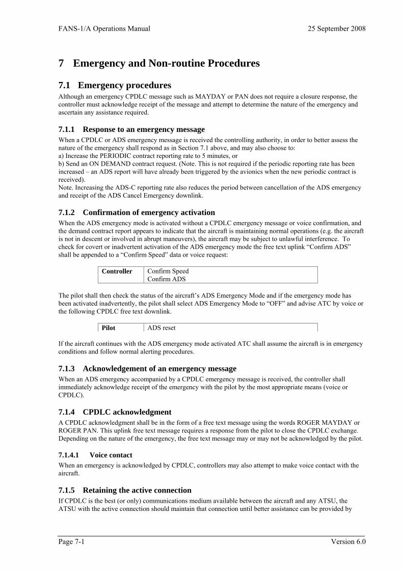
FANS-1/A Operations Manual 25 September 2008
7 Emergency and Non-routine Procedures
7.1 Emergency procedures Although an emergency CPDLC message such as MAYDAY or PAN does not require a closure response, the controller must acknowledge receipt of the message and attempt to determine the nature of the emergency and ascertain any assistance required.
7.1.1 Response to an emergency message When a CPDLC or ADS emergency message is received the controlling authority, in order to better assess the nature of the emergency shall respond as in Section 7.1 above, and may also choose to: a) Increase the PERIODIC contract reporting rate to 5 minutes, or b) Send an ON DEMAND contract request. (Note. This is not required if the periodic reporting rate has been increased – an ADS report will have already been triggered by the avionics when the new periodic contract is received). Note. Increasing the ADS-C reporting rate also reduces the period between cancellation of the ADS emergency and receipt of the ADS Cancel Emergency downlink.
7.1.2 Confirmation of emergency activation When the ADS emergency mode is activated without a CPDLC emergency message or voice confirmation, and the demand contract report appears to indicate that the aircraft is maintaining normal operations (e.g. the aircraft is not in descent or involved in abrupt maneuvers), the aircraft may be subject to unlawful interference. To check for covert or inadvertent activation of the ADS emergency mode the free text uplink “Confirm ADS” shall be appended to a “Confirm Speed” data or voice request:
Controller Confirm Speed Confirm ADS
The pilot shall then check the status of the aircraft’s ADS Emergency Mode and if the emergency mode has been activated inadvertently, the pilot shall select ADS Emergency Mode to “OFF” and advise ATC by voice or the following CPDLC free text downlink.
Pilot ADS reset If the aircraft continues with the ADS emergency mode activated ATC shall assume the aircraft is in emergency conditions and follow normal alerting procedures.
7.1.3 Acknowledgement of an emergency message When an ADS emergency accompanied by a CPDLC emergency message is received, the controller shall immediately acknowledge receipt of the emergency with the pilot by the most appropriate means (voice or CPDLC).
7.1.4 CPDLC acknowledgment A CPDLC acknowledgment shall be in the form of a free text message using the words ROGER MAYDAY or ROGER PAN. This uplink free text message requires a response from the pilot to close the CPDLC exchange. Depending on the nature of the emergency, the free text message may or may not be acknowledged by the pilot.
7.1.4.1 Voice contact When an emergency is acknowledged by CPDLC, controllers may also attempt to make voice contact with the aircraft.
7.1.5 Retaining the active connection If CPDLC is the best (or only) communications medium available between the aircraft and any ATSU, the ATSU with the active connection should maintain that connection until better assistance can be provided by
Page 7-1 Version 6.0
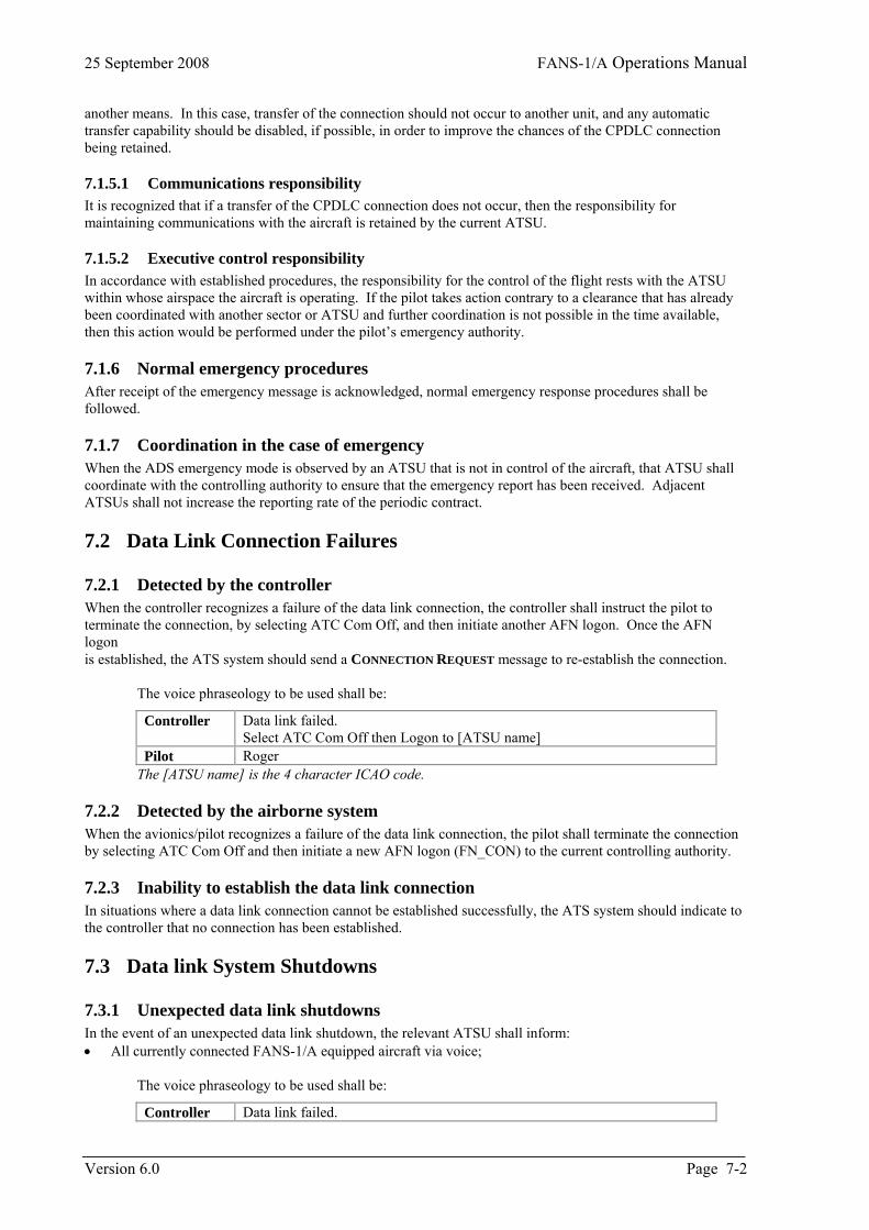
25 September 2008 FANS-1/A Operations Manual
another means. In this case, transfer of the connection should not occur to another unit, and any automatic transfer capability should be disabled, if possible, in order to improve the chances of the CPDLC connection being retained.
7.1.5.1 Communications responsibility It is recognized that if a transfer of the CPDLC connection does not occur, then the responsibility for maintaining communications with the aircraft is retained by the current ATSU.
7.1.5.2 Executive control responsibility In accordance with established procedures, the responsibility for the control of the flight rests with the ATSU within whose airspace the aircraft is operating. If the pilot takes action contrary to a clearance that has already been coordinated with another sector or ATSU and further coordination is not possible in the time available, then this action would be performed under the pilot’s emergency authority.
7.1.6 Normal emergency procedures After receipt of the emergency message is acknowledged, normal emergency response procedures shall be followed.
7.1.7 Coordination in the case of emergency When the ADS emergency mode is observed by an ATSU that is not in control of the aircraft, that ATSU shall coordinate with the controlling authority to ensure that the emergency report has been received. Adjacent ATSUs shall not increase the reporting rate of the periodic contract.
7.2 Data Link Connection Failures
7.2.1 Detected by the controller When the controller recognizes a failure of the data link connection, the controller shall instruct the pilot to terminate the connection, by selecting ATC Com Off, and then initiate another AFN logon. Once the AFN logon is established, the ATS system should send a CONNECTION REQUEST message to re-establish the connection.
The voice phraseology to be used shall be:
Controller Data link failed. Select ATC Com Off then Logon to [ATSU name]
Pilot Roger The [ATSU name] is the 4 character ICAO code.
7.2.2 Detected by the airborne system When the avionics/pilot recognizes a failure of the data link connection, the pilot shall terminate the connection by selecting ATC Com Off and then initiate a new AFN logon (FN_CON) to the current controlling authority.
7.2.3 Inability to establish the data link connection In situations where a data link connection cannot be established successfully, the ATS system should indicate to the controller that no connection has been established.
7.3 Data link System Shutdowns
7.3.1 Unexpected data link shutdowns In the event of an unexpected data link shutdown, the relevant ATSU shall inform: • All currently connected FANS-1/A equipped aircraft via voice;
The voice phraseology to be used shall be:
Controller Data link failed.
Version 6.0 Page 7-2
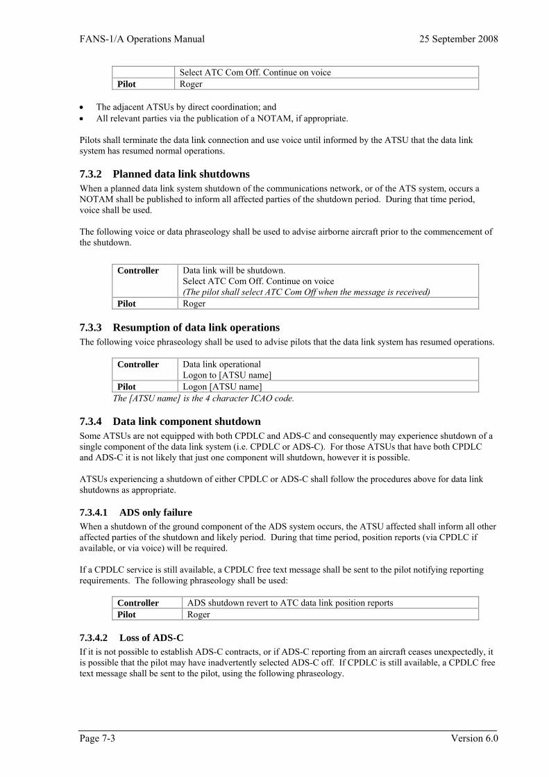
FANS-1/A Operations Manual 25 September 2008
Select ATC Com Off. Continue on voice Pilot Roger
• The adjacent ATSUs by direct coordination; and • All relevant parties via the publication of a NOTAM, if appropriate. Pilots shall terminate the data link connection and use voice until informed by the ATSU that the data link system has resumed normal operations.
7.3.2 Planned data link shutdowns When a planned data link system shutdown of the communications network, or of the ATS system, occurs a NOTAM shall be published to inform all affected parties of the shutdown period. During that time period, voice shall be used. The following voice or data phraseology shall be used to advise airborne aircraft prior to the commencement of the shutdown.
Controller Data link will be shutdown. Select ATC Com Off. Continue on voice (The pilot shall select ATC Com Off when the message is received)
Pilot Roger
7.3.3 Resumption of data link operations The following voice phraseology shall be used to advise pilots that the data link system has resumed operations.
Controller Data link operational Logon to [ATSU name]
Pilot Logon [ATSU name] The [ATSU name] is the 4 character ICAO code.
7.3.4 Data link component shutdown Some ATSUs are not equipped with both CPDLC and ADS-C and consequently may experience shutdown of a single component of the data link system (i.e. CPDLC or ADS-C). For those ATSUs that have both CPDLC and ADS-C it is not likely that just one component will shutdown, however it is possible. ATSUs experiencing a shutdown of either CPDLC or ADS-C shall follow the procedures above for data link shutdowns as appropriate.
7.3.4.1 ADS only failure When a shutdown of the ground component of the ADS system occurs, the ATSU affected shall inform all other affected parties of the shutdown and likely period. During that time period, position reports (via CPDLC if available, or via voice) will be required. If a CPDLC service is still available, a CPDLC free text message shall be sent to the pilot notifying reporting requirements. The following phraseology shall be used:
Controller ADS shutdown revert to ATC data link position reports Pilot Roger
7.3.4.2 Loss of ADS-C If it is not possible to establish ADS-C contracts, or if ADS-C reporting from an aircraft ceases unexpectedly, it is possible that the pilot may have inadvertently selected ADS-C off. If CPDLC is still available, a CPDLC free text message shall be sent to the pilot, using the following phraseology.
Page 7-3 Version 6.0
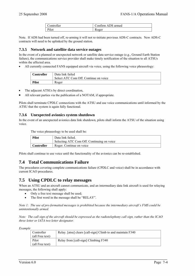
25 September 2008 FANS-1/A Operations Manual
Controller Confirm ADS armed Pilot Roger
Note. If ADS had been turned off, re-arming it will not re-initiate previous ADS-C contracts. New ADS-C contracts will need to be uplinked by the ground station.
7.3.5 Network and satellite data service outages In the event of a planned or unexpected network or satellite data service outage (e.g., Ground Earth Station failure), the communications service provider shall make timely notification of the situation to all ATSUs within the affected area. • All currently connected FANS equipped aircraft via voice, using the following voice phraseology:
Controller Data link failed
Select ATC Com Off. Continue on voice Pilot Roger
• The adjacent ATSUs by direct coordination, • All relevant parties via the publication of a NOTAM, if appropriate. Pilots shall terminate CPDLC connections with the ATSU and use voice communications until informed by the ATSU that the system is again fully functional.
7.3.6 Unexpected avionics system shutdown In the event of an unexpected avionics data link shutdown, pilots shall inform the ATSU of the situation using voice.
The voice phraseology to be used shall be:
Pilot Data link failed. Selecting ATC Com Off. Continuing on voice
Controller Roger. Continue on voice Pilots shall continue to use voice until the functionality of the avionics can be re-established.
7.4 Total Communications Failure The procedures covering complete communications failure (CPDLC and voice) shall be in accordance with current ICAO procedures.
7.5 Using CPDLC to relay messages When an ATSU and an aircraft cannot communicate, and an intermediary data link aircraft is used for relaying messages, the following shall apply:
• Only a free text message shall be used; • The first word in the message shall be “RELAY”.
Note 1: The use of pre-formatted messages is prohibited because the intermediary aircraft’s FMS could be unintentionally armed. Note: The call sign of the aircraft should be expressed as the radiotelephony call sign, rather than the ICAO three letter or IATA two letter designator. Example
Controller (all Free text)
Relay. [atsu] clears [call-sign] Climb to and maintain F340
Pilot (all Free text)
Relay from [call-sign] Climbing F340
Version 6.0 Page 7-4
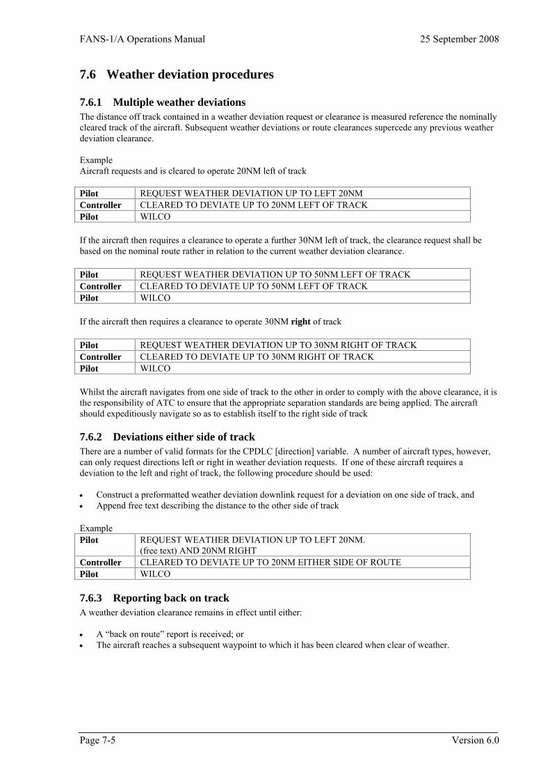
FANS-1/A Operations Manual 25 September 2008
Page 7-5 Version 6.0
7.6 Weather deviation procedures
7.6.1 Multiple weather deviations The distance off track contained in a weather deviation request or clearance is measured reference the nominally cleared track of the aircraft. Subsequent weather deviations or route clearances supercede any previous weather deviation clearance. Example Aircraft requests and is cleared to operate 20NM left of track Pilot REQUEST WEATHER DEVIATION UP TO LEFT 20NM Controller CLEARED TO DEVIATE UP TO 20NM LEFT OF TRACK Pilot WILCO If the aircraft then requires a clearance to operate a further 30NM left of track, the clearance request shall be based on the nominal route rather in relation to the current weather deviation clearance. Pilot REQUEST WEATHER DEVIATION UP TO 50NM LEFT OF TRACK Controller CLEARED TO DEVIATE UP TO 50NM LEFT OF TRACK Pilot WILCO If the aircraft then requires a clearance to operate 30NM right of track Pilot REQUEST WEATHER DEVIATION UP TO 30NM RIGHT OF TRACK Controller CLEARED TO DEVIATE UP TO 30NM RIGHT OF TRACK Pilot WILCO Whilst the aircraft navigates from one side of track to the other in order to comply with the above clearance, it is the responsibility of ATC to ensure that the appropriate separation standards are being applied. The aircraft should expeditiously navigate so as to establish itself to the right side of track
7.6.2 Deviations either side of track There are a number of valid formats for the CPDLC [direction] variable. A number of aircraft types, however, can only request directions left or right in weather deviation requests. If one of these aircraft requires a deviation to the left and right of track, the following procedure should be used: • Construct a preformatted weather deviation downlink request for a deviation on one side of track, and • Append free text describing the distance to the other side of track Example Pilot REQUEST WEATHER DEVIATION UP TO LEFT 20NM.
(free text) AND 20NM RIGHT Controller CLEARED TO DEVIATE UP TO 20NM EITHER SIDE OF ROUTE Pilot WILCO
7.6.3 Reporting back on track A weather deviation clearance remains in effect until either: • A “back on route” report is received; or • The aircraft reaches a subsequent waypoint to which it has been cleared when clear of weather.

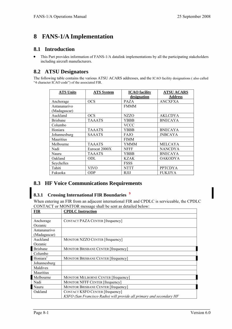
FANS-1/A Operations Manual 25 September 2008
Page 8-1 Version 6.0
8 FANS-1/A Implementation
8.1 Introduction • This Part provides information of FANS-1/A datalink implementations by all the participating stakeholders
including aircraft manufacturers.
8.2 ATSU Designators The following table contains the various ATSU ACARS addresses, and the ICAO facility designations ( also called “4 character ICAO code”) of the associated FIR.
ATS Units ATS System ICAO facility designation
ATSU ACARS Address
Anchorage OCS PAZA ANCXFXA Antananarivo (Madagascar)
FMMM
Auckland OCS NZZO AKLCDYA Brisbane TAAATS YBBB BNECAYA Columbo VCCC Honiara TAAATS YBBB BNECAYA Johannesburg SAAATS FAJO JNBCAYA Mauritius FIMM Melbourne TAAATS YMMM MELCAYA Nadi Eurocat 2000X NFFF NANCDYA Nauru TAAATS YBBB BNECAYA Oakland ODL KZAK OAKODYA Seychelles FSSS Tahiti VIVO NTTT PPTCDYA Fukuoka ODP RJJJ FUKJJYA
8.3 HF Voice Communications Requirements
8.3.1 Crossing International FIR Boundaries 9 When entering an FIR from an adjacent international FIR and CPDLC is serviceable, the CPDLC CONTACT or MONITOR message shall be sent as detailed below: FIR CPDLC Instruction
Anchorage Oceanic
CONTACT PAZA CENTER [frequency]
Antananarivo (Madagascar)
Auckland Oceanic
MONITOR NZZO CENTER [frequency]
Brisbane MONITOR BRISBANE CENTER [frequency] Columbo Honiara1 MONITOR BRISBANE CENTER [frequency] Johannesburg Maldives Mauritius Melbourne MONITOR MELBORNE CENTER [frequency] Nadi MONITOR NFFF CENTER [frequency] Nauru MONITOR BRISBANE CENTER [frequency] Oakland CONTACT KSFO CENTER [frequency]
KSFO (San Francisco Radio) will provide all primary and secondary HF
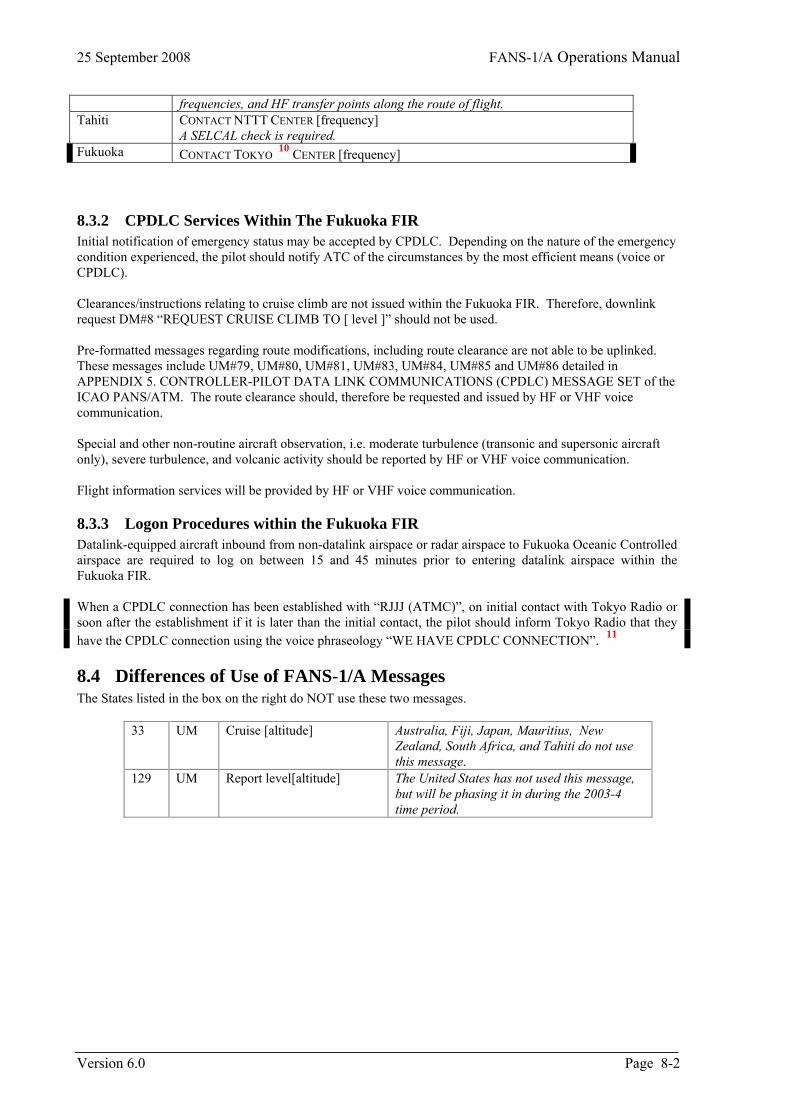
25 September 2008 FANS-1/A Operations Manual
frequencies, and HF transfer points along the route of flight. Tahiti CONTACT NTTT CENTER [frequency]
A SELCAL check is required. Fukuoka CONTACT TOKYO
10 CENTER [frequency]
8.3.2 CPDLC Services Within The Fukuoka FIR Initial notification of emergency status may be accepted by CPDLC. Depending on the nature of the emergency condition experienced, the pilot should notify ATC of the circumstances by the most efficient means (voice or CPDLC). Clearances/instructions relating to cruise climb are not issued within the Fukuoka FIR. Therefore, downlink request DM#8 “REQUEST CRUISE CLIMB TO [ level ]” should not be used. Pre-formatted messages regarding route modifications, including route clearance are not able to be uplinked. These messages include UM#79, UM#80, UM#81, UM#83, UM#84, UM#85 and UM#86 detailed in APPENDIX 5. CONTROLLER-PILOT DATA LINK COMMUNICATIONS (CPDLC) MESSAGE SET of the ICAO PANS/ATM. The route clearance should, therefore be requested and issued by HF or VHF voice communication. Special and other non-routine aircraft observation, i.e. moderate turbulence (transonic and supersonic aircraft only), severe turbulence, and volcanic activity should be reported by HF or VHF voice communication. Flight information services will be provided by HF or VHF voice communication.
8.3.3 Logon Procedures within the Fukuoka FIR Datalink-equipped aircraft inbound from non-datalink airspace or radar airspace to Fukuoka Oceanic Controlled airspace are required to log on between 15 and 45 minutes prior to entering datalink airspace within the Fukuoka FIR. When a CPDLC connection has been established with “RJJJ (ATMC)”, on initial contact with Tokyo Radio or soon after the establishment if it is later than the initial contact, the pilot should inform Tokyo Radio that they have the CPDLC connection using the voice phraseology “WE HAVE CPDLC CONNECTION”. 11
8.4 Differences of Use of FANS-1/A Messages The States listed in the box on the right do NOT use these two messages.
Australia, Fiji, Japan, Mauritius, New Zealand, South Africa, and Tahiti do not use this message.
33 UM Cruise [altitude]
129 UM Report level[altitude] The United States has not used this message, but will be phasing it in during the 2003-4 time period.
Version 6.0 Page 8-2
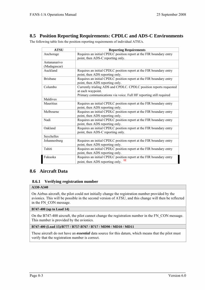
FANS-1/A Operations Manual 25 September 2008
8.5 Position Reporting Requirements: CPDLC and ADS-C Environments The following table lists the position reporting requirements of individual ATSUs.
ATSU Reporting Requirements
Anchorage Requires an initial CPDLC position report at the FIR boundary entry point, then ADS-C reporting only.
Antananarivo (Madagascar)
Auckland Requires an initial CPDLC position report at the FIR boundary entry point, then ADS reporting only.
Brisbane Requires an initial CPDLC position report at the FIR boundary entry point, then ADS reporting only.
Columbo Currently trialing ADS and CPDLC. CPDLC position reports requested at each waypoint. Primary communications via voice. Full HF reporting still required
Maldives Mauritius Requires an initial CPDLC position report at the FIR boundary entry
point, then ADS reporting only. Melbourne Requires an initial CPDLC position report at the FIR boundary entry
point, then ADS reporting only. Nadi Requires an initial CPDLC position report at the FIR boundary entry
point, then ADS reporting only. Oakland Requires an initial CPDLC position report at the FIR boundary entry
point, then ADS-C reporting only. Seychelles Johannesburg Requires an initial CPDLC position report at the FIR boundary entry
point, then ADS reporting only. Tahiti Requires an initial CPDLC position report at the FIR boundary entry
point, then ADS reporting only. Fukuoka Requires an initial CPDLC position report at the FIR boundary entry
point, then ADS reporting only. 12
8.6 Aircraft Data
8.6.1 Verifying registration number A330-A340
On Airbus aircraft, the pilot could not initially change the registration number provided by the avionics. This will be possible in the second version of ATSU, and this change will then be reflected in the FN_CON message.
B747-400 (up to Load 14)
On the B747-400 aircraft, the pilot cannot change the registration number in the FN_CON message. This number is provided by the avionics.
B747-400 (Load 15)/B777 / B757-B767 / B717 / MD90 / MD10 / MD11
These aircraft do not have an essential data source for this datum, which means that the pilot must verify that the registration number is correct.
Page 8-3 Version 6.0
25 September 2008 FANS-1/A Operations Manual
8.6.2 CPDLC connection requests A330-A340
B747-400 / B777 / B757-B767 / B717 / MD90 / MD10 / MD11
• The only CONNECTION REQUEST message processed normally by FANS-1 is the first CONNECTION REQUEST following an AFN logon (i.e., an AFN logon initiated when no CPDLC connection exists).
• If the CPDLC connection in the avionics is not terminated, and a new AFN logon transmitted, before sending the new CONNECTION REQUEST message any subsequent CONNECTION REQUEST messages received from that ATSU are processed, however they have no effect on the “active” connection (i.e. the avionics is not informed of an ATS system shutdown and will therefore consider that the original connection is still active).
• The avionics will not accept a connection if the AFN logon is initiated manually by the pilot while another connection was active, even if the active connection is terminated before the connection from the new ATSU is received
8.6.3 Flight crew display:- response and acknowledgment A330-A340
In response to an uplink message that requires a closure response (WILCO, ROGER, AFFIRM, UNABLE, NEGATIVE), the pilot is presented with prompts corresponding to the closure responses required by DO-219 for the specific uplink message. EG prompts presented upon receipt of an uplink clearance are WILCO, UNABLE, and STANDBY.
B747-400 / B777 / B757-B767 / B717 / MD90 / MD10 / MD11
In response to an uplink message that requires a response element (WILCO, ROGER, AFFIRM, UNABLE or NEGATIVE), the pilot is presented with two prompts (Accept and Reject).
• If the correct response to the uplink message is affirmative (WILCO, ROGER, or AFFIRM), then the pilot will select the Accept prompt.
• If the correct response to the uplink message is negative (UNABLE or NEGATIVE), then the pilot will select the Reject prompt.
When the pilot selects either the Accept or the Reject prompt, the FANS-1 automatically transmits the correct response (WILCO, ROGER, AFFIRM, UNABLE, or NEGATIVE) for the corresponding message.
On the FANS-1 equipped aircraft, the pilot cannot add any other element to a positive response.
Version 6.0 Page 8-4
FANS-1/A Operations Manual 25 September 2008
8.6.4 FMS processing of waypoints A330-A340
The FMS cannot distinguish between ATC mandatory waypoints and waypoints inserted by the pilot. However, the pilot can over-write any avionics-determined default data contained in reports and confirm messages.
B747-400
The FMC’s on Boeing aircraft do not distinguish between ATC mandatory waypoints and FMC sequenced waypoints for position reports. Additionally, the FANS-1 of the B747-400 aircraft does not permit the pilot to overwrite the FMC-determined default “reported waypoint” position in downlink DM#45 - REPORTED WAYPOINT. However, the FANS-1 of the B747-400 aircraft does allow the pilot to overwrite the FMC-determined default time (in particular, in response to uplink UM#138 -CONFIRM TIME OVER REPORTED WAYPOINT).
Non-use of uplink UM#139 for B747-400 aircraft The uplink message UM#139 - CONFIRM REPORTED WAYPOINT should not be sent to B747-400 aircraft.
B777 / B757-B767 / B717 / MD90 / MD10 / MD11
The FMC’s on Boeing aircraft do not distinguish between ATC mandatory waypoints and FMC sequenced waypoints for position reports. However, the FANS-1 of these aircraft will allow the pilot to overwrite the FMC-determined default “reported waypoint” position and time (Downlink element DM#45)
8.6.5 Multiple request messages A330-A340
There is no network acknowledgment timer on Airbus aircraft for the establishment of a connection. Once CPDLC is established, there is a timer which is currently set at 2 minutes.
B747-400
If the network acknowledgment to a downlink message is not received by the B747-400 aircraft’s ACARS MU within a time period set in the Navigation Database or Operational Program Configuration (OPC) file, the FANS-1 closes the message and an alert is triggered to the pilot. This alert may prompt the pilot to re-send the message. The timer value was 2 minutes up to Load 14, but will be set to 5 minutes with the introduction of Load 15. If a second message is identical to the first, but with a different identification number, and both messages have been received and responded to by the controller the avionics will only recognize the reference number of the second message. The first message is considered by the avionics to have been unsuccessful. • In reply to the controller’s response to the first message, the avionics will send an INVALID
REFERENCE NUMBER ERROR. • The controller’s response to the second message will be processed normally.
In this case, if the controller ignores the first message, the connections to both ATS systems will not be lost when an END SERVICE message is received on board the aircraft.
Page 8-5 Version 6.0
25 September 2008 FANS-1/A Operations Manual
B757-B767 / B717 / MD90 / MD10 / MD11
When the network acknowledgment timer expires, it just “unlocks” the request pages, so that the pilot will be able to send another one. The time at which the network acknowledgement timer expires can be set in the Operational Program Configuration (OPC) file in the FMS. Currently, the value is set to 5 minutes.
B777
This network acknowledgment timer does not apply to the B777.
8.6.6 Waypoint sequencing A330-A340
Waypoint sequencing will only occur when the aircraft is within 7 NM of the flight plan track (as modified by any parallel offset that may have been entered). Therefore ADS-C waypoint change event reports and armed REPORT PASSING messages will not be transmitted automatically when the aircraft is outside these limits.
B747-400 / B757-B767 / B777 / MD90
Waypoint sequencing will only occur when the aircraft is within 21 NM of the flight plan track (as modified by any parallel offset that may have been entered). Therefore ADS-C waypoint change event reports and armed REPORT PASSING messages will not be transmitted automatically when the aircraft is outside these limits.
B717 / MD10 / MD11
Waypoint sequencing will only occur when the aircraft is within 7 NM of the flight plan track (as modified by any parallel offset that may have been entered). Therefore ADS-C waypoint change event reports and armed REPORT PASSING messages will not be transmitted automatically when the aircraft is outside these limits.
8.6.7 Network acknowledgement timer B747-400
The B747-400 FMC has a network acknowledgment timer as described in section 6.6.2A.i. of the Reference 1 ATS SR&O. If the network acknowledgment to a downlink message is not received before the timer expires, the flight crew is alerted and may assume that the message has not been sent. Once back “IN COMM” the ACARS MU will transmit any “queued” messages.
8.6.8 Open uplinks at time of transfer of communications B747-400 (Load 15) If there are OPEN uplinks in the Boeing B747-400 FMC's ATC LOG when the Current Data Authority initiates transfer of communication to the Next Data Authority, the FMC will allow transfer to the Next Data Authority (i.e. The FMC will not disconnect the next data authority). This allows a smooth transfer to the next Flight Information Region if there are open uplinks at the time of transfer.
Version 6.0 Page 8-6
FANS-1/A Operations Manual 25 September 2008
8.6.9 Offset using the FMS When a pilot is flying an FMS offset, the Airbus and Boeing parameters previously mentioned (7 NM and 21 NM respectively) are not an issue as all flight plan waypoints will be sequenced by the FMS without taking into account the offset distance being flown. However, when an offset is executed using the FMS, Boeing aircraft and Airbus aircraft will transmit intent and predicted route information as follows:
A330-A340
The Intent and Predicted Route Group information is projected along the offset route.
B747-400 / B777 / B757-B767 / B717 / MD90 / MD10 / MD11
The Predicted Route Group when flying an FMS offset is always along the offset route.
The projection of intent information currently depends on the aircraft type, and the version of software is installed as defined below:
B747-400 - Load 14 and before, towards the next FMS waypoint. Load 15 and after, along the offset path.
B757/B767 - Pegasus 99 and before, towards the next FMS waypoint. Pegasus 2000 and after, along the offset path.
B777 - Block Point 98, towards the next FMS waypoint. Block Point 99 and after, along the offset path.
MD90 - 920 FMS, towards the next FMS waypoint. 921 FMS and after, along the offset path.
MD10 / MD11 / B717 - Always along the offset path.
8.6.10 Duplicate uplink messages B747-400 (Load 15) If the Boeing B747-400 FMC receives an uplink message that is an exact duplicate of a previously received uplink message, the FMC will discard the duplicate message. This prevents the display of the INVALID ATC UPLINK scratch pad message which would otherwise be displayed when a duplicate uplink is received Note: Duplicate messages are an unavoidable characteristic of the datalink environment.
Page 8-7 Version 6.0
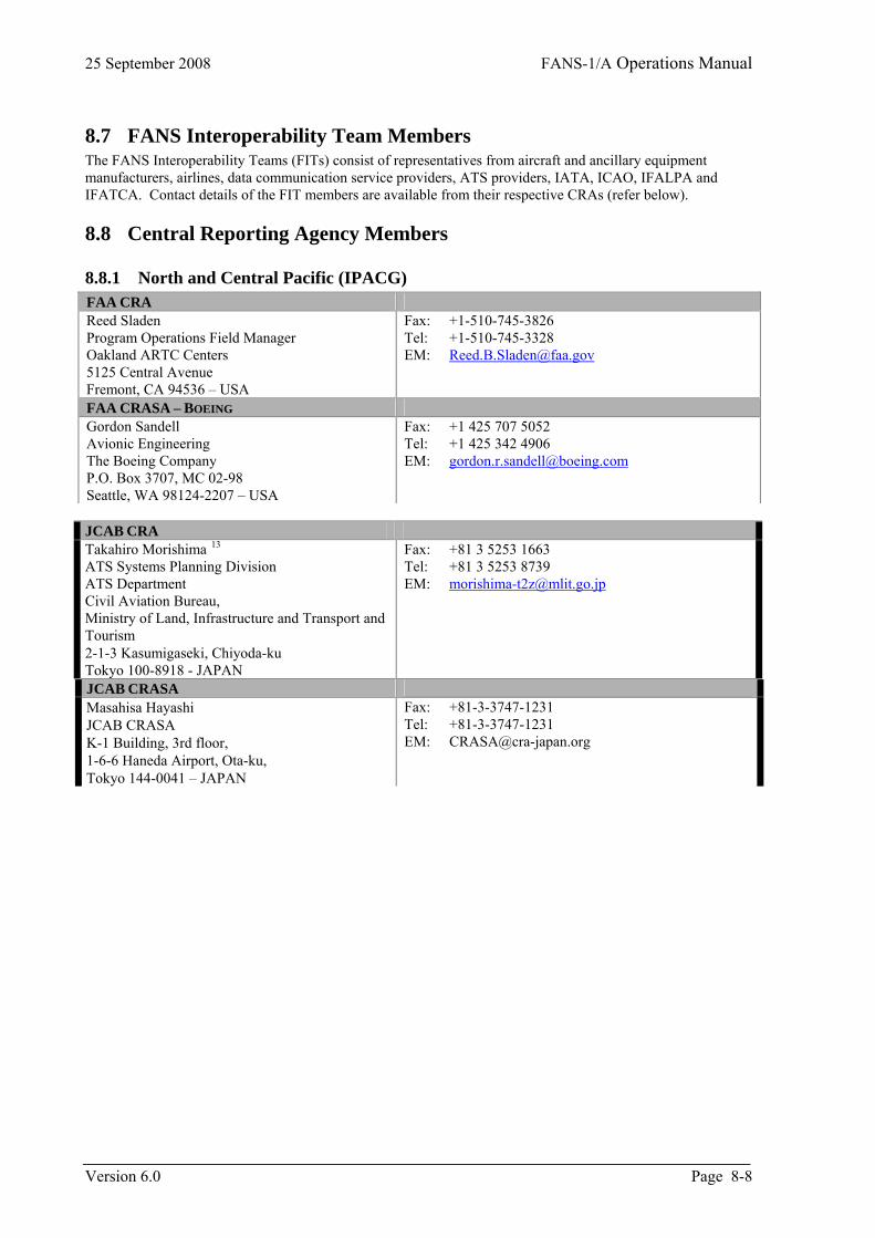
25 September 2008 FANS-1/A Operations Manual
Version 6.0 Page 8-8
8.7 FANS Interoperability Team Members The FANS Interoperability Teams (FITs) consist of representatives from aircraft and ancillary equipment manufacturers, airlines, data communication service providers, ATS providers, IATA, ICAO, IFALPA and IFATCA. Contact details of the FIT members are available from their respective CRAs (refer below).
8.8 Central Reporting Agency Members
8.8.1 North and Central Pacific (IPACG) FAA CRA Reed Sladen Program Operations Field Manager Oakland ARTC Centers 5125 Central Avenue Fremont, CA 94536 – USA
Fax: +1-510-745-3826 Tel: +1-510-745-3328 EM: [email protected]
FAA CRASA – BOEING Gordon Sandell Avionic Engineering The Boeing Company P.O. Box 3707, MC 02-98 Seattle, WA 98124-2207 – USA
Fax: +1 425 707 5052 Tel: +1 425 342 4906 EM: [email protected]
JCAB CRA Takahiro Morishima 13 ATS Systems Planning Division ATS Department Civil Aviation Bureau, Ministry of Land, Infrastructure and Transport and Tourism 2-1-3 Kasumigaseki, Chiyoda-ku Tokyo 100-8918 - JAPAN
Fax: +81 3 5253 1663 Tel: +81 3 5253 8739 EM: [email protected]
JCAB CRASA Masahisa Hayashi JCAB CRASA K-1 Building, 3rd floor, 1-6-6 Haneda Airport, Ota-ku, Tokyo 144-0041 – JAPAN
Fax: +81-3-3747-1231 Tel: +81-3-3747-1231 EM: [email protected]
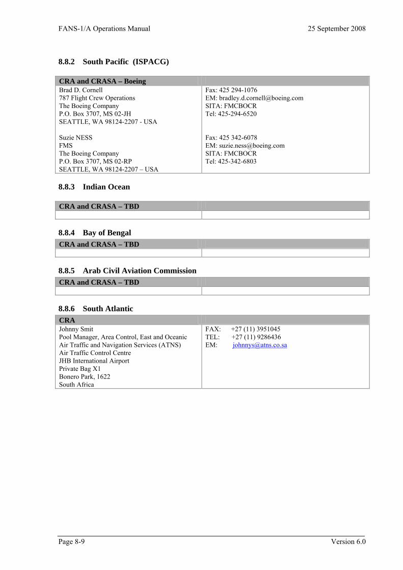
FANS-1/A Operations Manual 25 September 2008
Page 8-9 Version 6.0
8.8.2 South Pacific (ISPACG) CRA and CRASA – Boeing Brad D. Cornell 787 Flight Crew Operations The Boeing Company P.O. Box 3707, MS 02-JH SEATTLE, WA 98124-2207 - USA Suzie NESS FMS The Boeing Company P.O. Box 3707, MS 02-RP SEATTLE, WA 98124-2207 – USA
Fax: 425 294-1076 EM: [email protected] SITA: FMCBOCR Tel: 425-294-6520 Fax: 425 342-6078 EM: [email protected] SITA: FMCBOCR Tel: 425-342-6803
8.8.3 Indian Ocean CRA and CRASA – TBD
8.8.4 Bay of Bengal CRA and CRASA – TBD
8.8.5 Arab Civil Aviation Commission CRA and CRASA – TBD
8.8.6 South Atlantic CRA Johnny Smit Pool Manager, Area Control, East and Oceanic Air Traffic and Navigation Services (ATNS) Air Traffic Control Centre JHB International Airport Private Bag X1 Bonero Park, 1622 South Africa
FAX: +27 (11) 3951045 TEL: +27 (11) 9286436 EM: [email protected]

FANS-1/A Operations Manual 25 September 2008
9 Continental CPDLC Implementation
9.1 Introduction This section provides guidance on the implementation of FANS-1/A datalink operations in en route continental (domestic) airspace based on the operational experience of a number of centres that are using CPDLC as a supplement to VHF voice. The purpose of this guidance material is to ensure that the concepts and procedures for continental FANS-1/A data link usage are globally standardized as far as is possible. The recommended procedures contained in this section are drawn from procedures that have been validated over several years of operational use within continental en route airspaces.
9.2 Concepts
9.2.1 Supplement to Voice Implementation of CPDLC into continental airspace is intended as a supplement to the use of VHF voice and the intent is to build a single communications environment where both voice and CPDLC are considered as being normal Air Traffic Management (ATM) tools.
9.2.2 Reduced Message Set CPDLC in continental airspace uses a reduced set of message elements as a supplement to VHF voice communications. A recommended message sub-set is included at the end of this section, but it is expected that there may be slight variations from centre to centre depending on specific environments. It is extremely important that Air Traffic Service Providers publish a list of the functions that will be served by CPDLC so that crew expectations can be modified from one environment to the next.
9.2.3 Airspace The use of CPDLC in continental airspace is intended primarily for aircraft operating within en-route sectors. Depending on the actual operational environment where the implementation is to occur (for example, radar or non-radar airspace), the only change to the single communications environment during the progression of a specific flight would be the mix of voice and CPDLC transmissions. As an example of the changing mix of media in a single communications environment, a non-radar environment might use a roughly equal mix of voice and CPDLC, whereas the use of CPDLC might possibly be restricted to just the passing of Departure Clearances in some busier terminal environments.
9.3 Communications Media
9.3.1 Continental The ATC communications environment within data link enabled continental airspace is a defined mix of CPDLC and voice media.
9.3.2 Use of CPDLC in Continental Airspace The following procedures only apply to normal (non-emergency) operations. While the intent of these procedures is to develop a standardised and predictable environment using a combination of voice and CPDLC, the decision on whether voice or CPDLC is the more appropriate medium for use in a given operational situation will be made by the pilots and controllers involved.
9.3.3 Strategic CPDLC Application As a supplement to VHF voice, CPDLC is intended to be restricted to the passing of strategic information. Strategic information involves routine, non-time-critical communications, and includes examples such as the passing of amended flight levels, amended routes, speed control messages, frequency changes, and SSR codes, when the speed of delivery is not critical to safety.
Page 9-1 Version 6.0
25 September 2008 FANS-1/A Operations Manual
9.3.4 Tactical Voice Tactical, time-critical instructions, such as intervention required to maintain separation, are intended to be handled by voice communications.
9.3.5 Voice Precedence Voice instructions and acknowledgments shall have precedence over CPDLC messages at all times. In the event that any ambiguity exists in a message or message exchange, then the controller/pilot shall revert to voice communications for clarification.
9.3.6 Imposing Voice Communications If a controller or pilot believes that the presiding operational circumstances are not suitable for the use of CPDLC, then either may suspend the use of CPDLC. Whenever voice is required to be the sole communications medium, notification shall be made by the following phraseologies: Controller initiated suspension - “[callsign] CPDLC use suspended. Revert to voice.” Pilot initiated suspension - “[callsign] suspending CPDLC. Reverting to voice.” Note: Notification of CPDLC being suspended is intended to ensure that CPDLC is not used during the prevailing circumstances – the crew should not initiate a disconnection from CPDLC unless specifically advised by the controller. If a disconnection from CPDLC is required, then either the phrase “[callsign] Select ATC Comm Off” shall be used, or the controller will perform the disconnection via the ground system.
9.3.7 Change from Strategic to Tactical Situation If the traffic situation should quickly change to the point where the controller no longer believes that there is sufficient time for a datalink exchange to be completed without safety, separation, or situational awareness being affected, then the controller should revert to voice. Any previously issued CPDLC clearance or instruction that is being overridden by the change to voice shall be specifically referred to in the voice communication. Where necessary, any open CPDLC messages resulting from a sudden change from CPDLC to voice should only be dealt with after the tactical situation has been resolved.
9.3.8 Message Compliance and Responses Flight crew shall either comply with uplink CPDLC instructions or respond with UNABLE, and shall respond to uplink messages using CPDLC whenever possible.
9.3.9 Climb/Descent Phase Due to cockpit workload and crew head-down time in busier phases of flight, consideration should be given to the types of messages exchanged by CPDLC during the climb and descent phases and whether those messages provide operational benefit over voice transmissions.
9.3.10 Crossing CPDLC System Boundaries Flight crew shall ensure that the correct centre is displayed as the Active Centre following a transfer of the CPDLC connection from one ATS Unit to another.
9.3.11 Jurisdiction Over Aircraft Controllers must ensure that CPDLC clearances are sent only to aircraft under their jurisdiction.
9.3.12 Dialogues During CPDLC Transfer Flight crew and controllers should not initiate a CPDLC dialogue within two minutes of a boundary crossing when the transfer of CPDLC will occur from one ATS Unit to another.
9.4 Message Set The following message set is the recommended maximum sub-set of the full CPDLC message set for continental CPDLC use. This sub-set has been defined from a mix of proposed and current message elements intended for continental use by a number of States: MAAS Maastricht Upper Area Control Center (UAC) Miami 1A FAA Build 1A Program (Miami Centre)
Version 6.0 Page 9-2
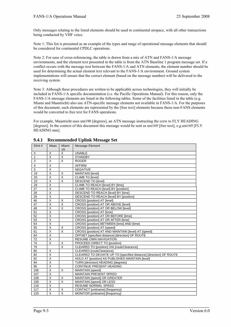
FANS-1/A Operations Manual 25 September 2008
Only messages relating to the listed elements should be used in continental airspace, with all other transactions being conducted by VHF voice. Note 1: This list is presented as an example of the types and range of operational message elements that should be considered for continental CPDLC operations. Note 2: For ease of cross-referencing, the table is drawn from a mix of ATN and FANS-1/A message environments, and the element text presented in the table is from the ATN Baseline 1 program message set. If a conflict occurs with the message text between the FANS-1/A and ATN elements, the element number should be used for determining the actual element text relevant to the FANS-1/A environment. Ground system implementations will ensure that the correct element (based on the message number) will be delivered to the receiving system. Note 3: Although these procedures are written to be applicable across technologies, they will initially be included in FANS-1/A specific documentation (i.e. the Pacific Operations Manual). For this reason, only the FANS-1/A message elements are listed in the following tables. Some of the facilities listed in the table (e.g. Miami and Maastricht) also use ATN-specific message elements not available in FANS-1/A. For the purposes of this document, such elements are represented by the [free text] elements because these non-FANS elements would be converted to free text for FANS operations. For example, Maastricht uses um190 [degrees], an ATN message instructing the crew to FLY HEADING [degrees]. In the context of this document this message would be sent as um169 [free text], e.g.um169 [FLY HEADING nnn].
9.4.1 Recommended Uplink Message Set Elmt # Maas Miami
1A Message Element
0 X X UNABLE 1 X X STANDBY 3 X X ROGER 4 X AFFIRM 5 X NEGATIVE 19 X X MAINTAIN [level] 20 X X CLIMB TO [level] 23 X X DESCEND TO [level] 26 X CLIMB TO REACH [level] BY [time] 27 X CLIMB TO REACH [level] BY [position] 28 X DESCEND TO REACH [level] BY [time] 29 X DESCEND TO REACH [level] BY [position] 46 X X CROSS [position] AT [level] 47 X X CROSS [position] AT OR ABOVE [level] 48 X X CROSS [position] AT OR BELOW [level] 51 X CROSS [position] AT [time] 52 X CROSS [position] AT OR BEFORE [time] 53 X CROSS [position] AT OR AFTER [time] 54 X CROSS [position] BETWEEN [time] AND [time] 55 X X CROSS [position] AT [speed] 61 X X CROSS [position] AT AND MAINTAIN [level] AT [speed] 64 X OFFSET [specified distance] [direction] OF ROUTE 72 X RESUME OWN NAVIGATION 74 X X PROCEED DIRECT TO [position] 79 X CLEARED TO [position] VIA [routeClearance] 80 X CLEARED [routeClearance] 82 X CLEARED TO DEVIATE UP TO [specified distance] [direction] OF ROUTE 92 X HOLD AT [position] AS PUBLISHED MAINTAIN [level] 94 X TURN [direction] HEADING [degrees] 96 X CONTINUE PRESENT HEADING 106 X X MAINTAIN [speed] 107 X MAINTAIN PRESENT SPEED 108 X X MAINTAIN [speed] OR GREATER 109 X X MAINTAIN [speed] OR LESS 116 X RESUME NORMAL SPEED 117 X X CONTACT [unitname] [frequency] 120 X X MONITOR [unitname] [frequency]
Page 9-3 Version 6.0
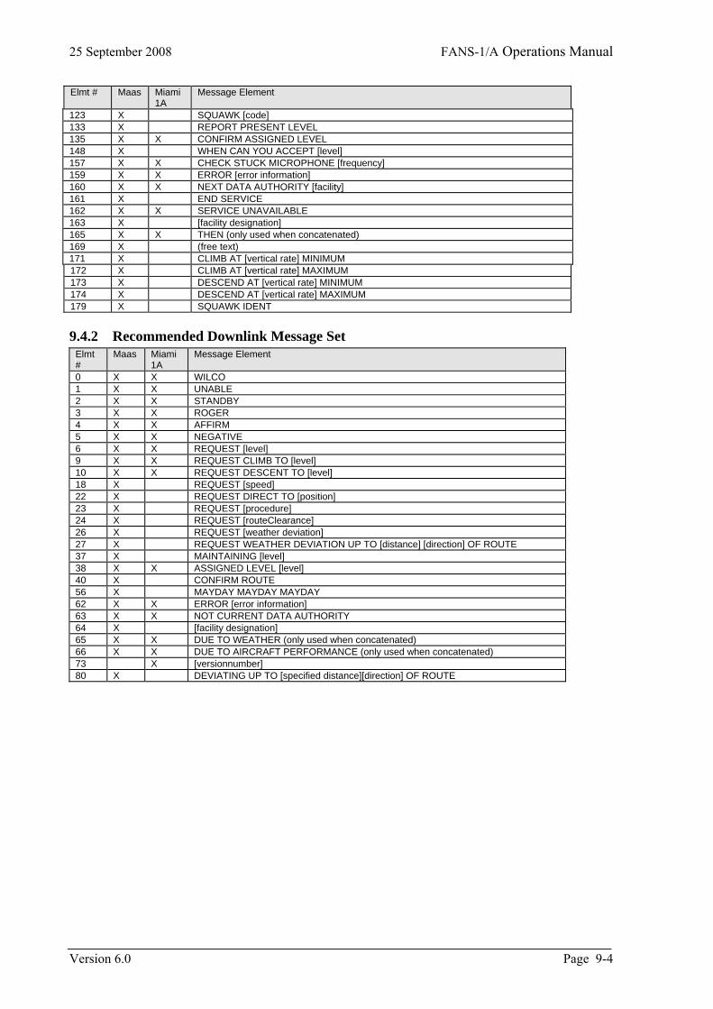
25 September 2008 FANS-1/A Operations Manual
Elmt # Maas Miami 1A
Message Element
123 X SQUAWK [code] 133 X REPORT PRESENT LEVEL 135 X X CONFIRM ASSIGNED LEVEL 148 X WHEN CAN YOU ACCEPT [level] 157 X X CHECK STUCK MICROPHONE [frequency] 159 X X ERROR [error information] 160 X X NEXT DATA AUTHORITY [facility] 161 X END SERVICE 162 X X SERVICE UNAVAILABLE 163 X [facility designation] 165 X X THEN (only used when concatenated) 169 X (free text) 171 X CLIMB AT [vertical rate] MINIMUM 172 X CLIMB AT [vertical rate] MAXIMUM 173 X DESCEND AT [vertical rate] MINIMUM 174 X DESCEND AT [vertical rate] MAXIMUM 179 X SQUAWK IDENT
9.4.2 Recommended Downlink Message Set Elmt #
Maas Miami Message Element 1A
0 X X WILCO 1 X X UNABLE 2 X X STANDBY 3 X X ROGER 4 X X AFFIRM 5 X X NEGATIVE 6 X X REQUEST [level] 9 X X REQUEST CLIMB TO [level] 10 X X REQUEST DESCENT TO [level] 18 X REQUEST [speed] 22 X REQUEST DIRECT TO [position] 23 X REQUEST [procedure] 24 X REQUEST [routeClearance] 26 X REQUEST [weather deviation] 27 X REQUEST WEATHER DEVIATION UP TO [distance] [direction] OF ROUTE 37 X MAINTAINING [level] 38 X X ASSIGNED LEVEL [level] 40 X CONFIRM ROUTE 56 X MAYDAY MAYDAY MAYDAY 62 X X ERROR [error information] 63 X X NOT CURRENT DATA AUTHORITY 64 X [facility designation] 65 X X DUE TO WEATHER (only used when concatenated) 66 X X DUE TO AIRCRAFT PERFORMANCE (only used when concatenated) 73 X [versionnumber] 80 X DEVIATING UP TO [specified distance][direction] OF ROUTE
Version 6.0 Page 9-4
FANS-1/A Operations Manual 25 September 2008
Page 10-5 Version 6.0
10 Procedures For State Aircraft Special Operations Note that this entire Section does not apply in the Fukuoka FIR.
10.1 Introduction The data link and voice communication requirements for CNS/ATM are being defined by international, regional, and national civil aviation authorities and are based on use of commercial communication systems. In the Oceanic and Remote Regions, data link has seen increased use and will eventually replace voice as the primary means of communication. The military has unique requirements insofar as using CPDLC. These requirements were never considered when the CPDLC message set was being developed. Many air and maritime air forces have the capability to conduct air-to-air refueling (AAR) operations. Although detailed procedures are dependent on aircraft type, mode of employment and national requirements, there is sufficient commonality for standard procedures to be developed to enhance operational interoperability. Many of these air and maritime air forces are making the transition to aeronautical data links and the use of Controller Pilot Data Link Communications (CPDLC) and Automatic Dependent Surveillance - Contract (ADS-C). The procedures outlined below describe the communications to be utilized by military aircraft in the attempt to promote harmonization in CPDLC and ADS-C procedures. These procedures have been developed utilizing a combination of existing CPDLC message elements and free text. Pro-forma free text messages DL67Land DL67M have been created to support these operations in the attempt to avoid the use of free text messages and for overall standardization. To the maximum extent possible, data link capable aircraft should adhere to established message architecture and avoid extraneous free text. The aim of this chapter is to provide a reference document covering military procedures to be used in an aeronautical data link environment. This chapter will provide guidance for air crews and air navigations service providers (ANSPs) in order to promote harmonized military air-to-air refueling operations in an aeronautical data link environment and lead to a better understanding of air-to-air refueling procedures and terminology.
10.2 Air-to-Air Refueling Air-to-air refueling is normally accomplished between 10,000 and 28,000 feet depending on receiver type, requiring both aircraft to descent for refueling. Refueling tracks are numbered and depicted on charts in domestic airspace and a few depicted in oceanic airspace. Oceanic refueling may also be conducted on non-designated tracks with an Altitude Reservation (ALTRV). In both cases, the refueling procedure is part of the filed flight plan. The flight plan always includes time, requested altitude block, Air Refueling Control Point (ARCP), Air Refueling Initial Point (ARIP), Air Refueling Exit Point (AREX) and intermediate refueling track points. If the procedure is depicted, its designation (ARxxx) is sufficient to define the track. In the oceanic environment, a refueling pattern may be part of an existing ALTRV. During the refueling phase all aircraft operate within the altitude block and fly the flight planned route along the refueling track. ADS contracts may be set with any aircraft but it is only necessary with the lead tanker and must correspond with a filed flight plan. Additionally, any other CPDLC report (i.e. REPORT PASSING [position], etc.) may be requested of the tanker in order to track the progress of the flight. The aircraft may or may not remain in a single formation in the altitude block for the remainder of the flight. There are no special CPDLC messages developed during this phase. A typical air-refueling pattern is illustrated below. The light green track represents the tanker’s intended route to the ARCP. The light blue track is the receiver’s intended route. Both aircraft file separate flight plans showing the specific aerial refueling locations. The dark blue track is the tanker’s orbit and rendezvous flight paths with the dark green track depicting the aerial refueling (AR) track. Three or more points can define the AR track. The ARIP is the point where the receiver enters the AR track. The ARCP is the reference point for the holding pattern where the tanker awaits the receiver. The AR track is between the ARCP and the AREX.
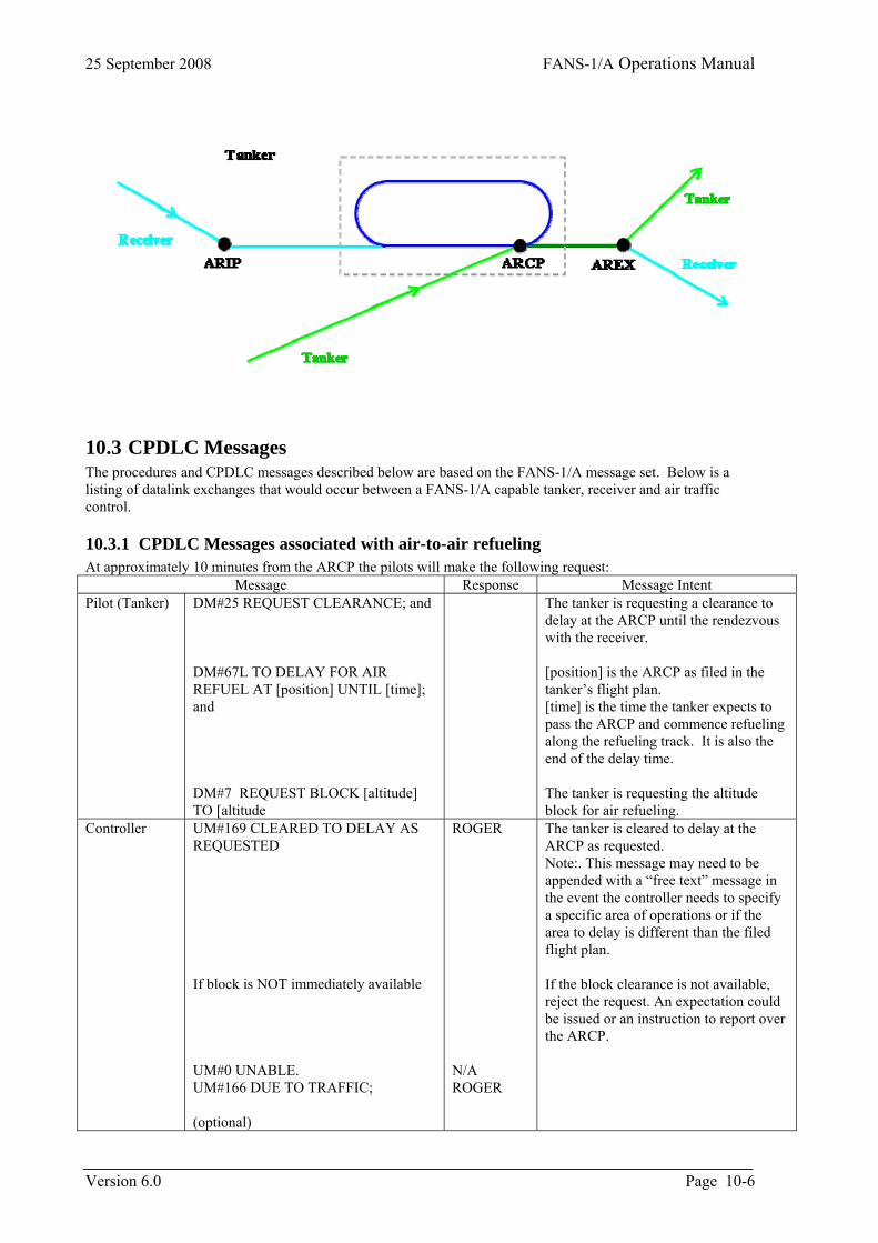
25 September 2008 FANS-1/A Operations Manual
10.3 CPDLC Messages The procedures and CPDLC messages described below are based on the FANS-1/A message set. Below is a listing of datalink exchanges that would occur between a FANS-1/A capable tanker, receiver and air traffic control.
10.3.1 CPDLC Messages associated with air-to-air refueling At approximately 10 minutes from the ARCP the pilots will make the following request:
Message Response Message Intent Pilot (Tanker) DM#25 REQUEST CLEARANCE; and
DM#67L TO DELAY FOR AIR REFUEL AT [position] UNTIL [time]; and DM#7 REQUEST BLOCK [altitude] TO [altitude
The tanker is requesting a clearance to delay at the ARCP until the rendezvous with the receiver. [position] is the ARCP as filed in the tanker’s flight plan. [time] is the time the tanker expects to pass the ARCP and commence refueling along the refueling track. It is also the end of the delay time. The tanker is requesting the altitude block for air refueling.�
Controller UM#169 CLEARED TO DELAY AS REQUESTED If block is NOT immediately available UM#0 UNABLE. UM#166 DUE TO TRAFFIC; (optional)
ROGER N/A ROGER
The tanker is cleared to delay at the ARCP as requested. Note:. This message may need to be appended with a “free text” message in the event the controller needs to specify a specific area of operations or if the area to delay is different than the filed flight plan. If the block clearance is not available, reject the request. An expectation could be issued or an instruction to report over the ARCP.
Version 6.0 Page 10-6
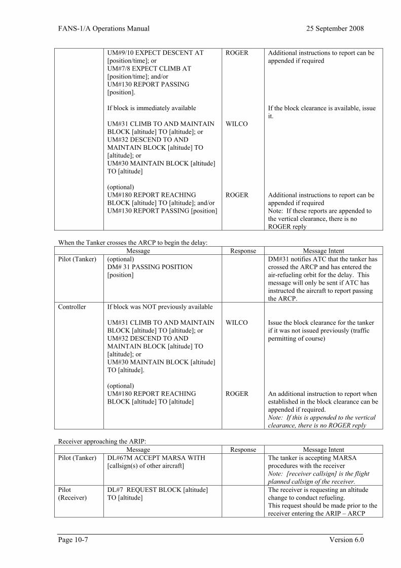
FANS-1/A Operations Manual 25 September 2008
UM#9/10 EXPECT DESCENT AT [position/time]; or UM#7/8 EXPECT CLIMB AT [position/time]; and/or UM#130 REPORT PASSING [position]. If block is immediately available UM#31 CLIMB TO AND MAINTAIN BLOCK [altitude] TO [altitude]; or UM#32 DESCEND TO AND MAINTAIN BLOCK [altitude] TO [altitude]; or UM#30 MAINTAIN BLOCK [altitude] TO [altitude] (optional) UM#180 REPORT REACHING BLOCK [altitude] TO [altitude]; and/or UM#130 REPORT PASSING [position]
ROGER WILCO ROGER
Additional instructions to report can be appended if required If the block clearance is available, issue it. Additional instructions to report can be appended if required Note: If these reports are appended to the vertical clearance, there is no ROGER reply�
When the Tanker crosses the ARCP to begin the delay:
Message Response Message Intent Pilot (Tanker) (optional)
DM# 31 PASSING POSITION [position]
DM#31 notifies ATC that the tanker has crossed the ARCP and has entered the air-refueling orbit for the delay. This message will only be sent if ATC has instructed the aircraft to report passing the ARCP.
Controller If block was NOT previously available UM#31 CLIMB TO AND MAINTAIN BLOCK [altitude] TO [altitude]; or UM#32 DESCEND TO AND MAINTAIN BLOCK [altitude] TO [altitude]; or UM#30 MAINTAIN BLOCK [altitude] TO [altitude]. (optional) UM#180 REPORT REACHING BLOCK [altitude] TO [altitude]
WILCO ROGER
Issue the block clearance for the tanker if it was not issued previously (traffic permitting of course) An additional instruction to report when established in the block clearance can be appended if required. Note: If this is appended to the vertical clearance, there is no ROGER reply�
Receiver approaching the ARIP:
Message Response Message Intent Pilot (Tanker) DL#67M ACCEPT MARSA WITH
[callsign(s) of other aircraft] The tanker is accepting MARSA
procedures with the receiver Note: [receiver callsign] is the flight planned callsign of the receiver.
Pilot (Receiver)
DL#7 REQUEST BLOCK [altitude] TO [altitude]
The receiver is requesting an altitude change to conduct refueling. This request should be made prior to the receiver entering the ARIP – ARCP
Page 10-7 Version 6.0
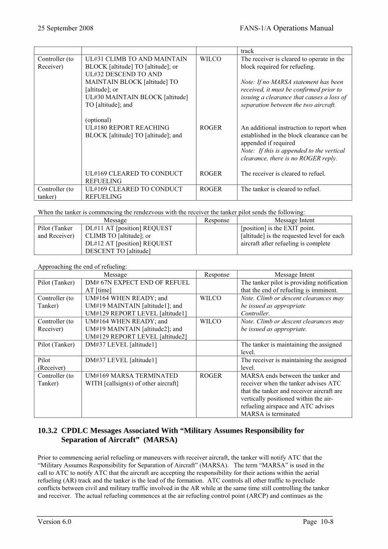
25 September 2008 FANS-1/A Operations Manual
track Controller (to Receiver)
UL#31 CLIMB TO AND MAINTAIN BLOCK [altitude] TO [altitude]; or UL#32 DESCEND TO AND MAINTAIN BLOCK [altitude] TO [altitude]; or UL#30 MAINTAIN BLOCK [altitude] TO [altitude]; and (optional) UL#180 REPORT REACHING BLOCK [altitude] TO [altitude]; and UL#169 CLEARED TO CONDUCT REFUELING
WILCO ROGER ROGER
The receiver is cleared to operate in the block required for refueling. Note: If no MARSA statement has been received, it must be confirmed prior to issuing a clearance that causes a loss of separation between the two aircraft. An additional instruction to report when established in the block clearance can be appended if required Note: If this is appended to the vertical clearance, there is no ROGER reply. The receiver is cleared to refuel.
Controller (to tanker)
UL#169 CLEARED TO CONDUCT REFUELING
ROGER The tanker is cleared to refuel.
When the tanker is commencing the rendezvous with the receiver the tanker pilot sends the following:
Message Response Message Intent Pilot (Tanker and Receiver)
DL#11 AT [position] REQUEST CLIMB TO [altitude]; or
DL#12 AT [position] REQUEST DESCENT TO [altitude] �
[position] is the EXIT point. [altitude] is the requested level for each aircraft after refueling is complete
Approaching the end of refueling:
Message Response Message Intent Pilot (Tanker) DM# 67N EXPECT END OF REFUEL
AT [time] The tanker pilot is providing notification
that the end of refueling is imminent. WILCO Note. Climb or descent clearances may
be issued as appropriate Controller.
Controller (to Tanker)
UM#164 WHEN READY; and UM#19 MAINTAIN [altitude1]; and UM#129 REPORT LEVEL [altitude1]�
Controller (to Receiver)
UM#164 WHEN READY; and UM#19 MAINTAIN [altitude2]; and UM#129 REPORT LEVEL [altitude2]
WILCO Note. Climb or descent clearances may be issued as appropriate.
Pilot (Tanker) DM#37 LEVEL [altitude1] The tanker is maintaining the assigned level.
Pilot (Receiver)
DM#37 LEVEL [altitude1] The receiver is maintaining the assigned level.
Controller (to Tanker)
UM#169 MARSA TERMINATED WITH [callsign(s) of other aircraft]
ROGER MARSA ends between the tanker and receiver when the tanker advises ATC that the tanker and receiver aircraft are vertically positioned within the air-refueling airspace and ATC advises MARSA is terminated�
10.3.2 CPDLC Messages Associated With “Military Assumes Responsibility for Separation of Aircraft” (MARSA)
Prior to commencing aerial refueling or maneuvers with receiver aircraft, the tanker will notify ATC that the “Military Assumes Responsibility for Separation of Aircraft” (MARSA). The term “MARSA” is used in the call to ATC to notify ATC that the aircraft are accepting the responsibility for their actions within the aerial refueling (AR) track and the tanker is the lead of the formation. ATC controls all other traffic to preclude conflicts between civil and military traffic involved in the AR while at the same time still controlling the tanker and receiver. The actual refueling commences at the air refueling control point (ARCP) and continues as the
Version 6.0 Page 10-8
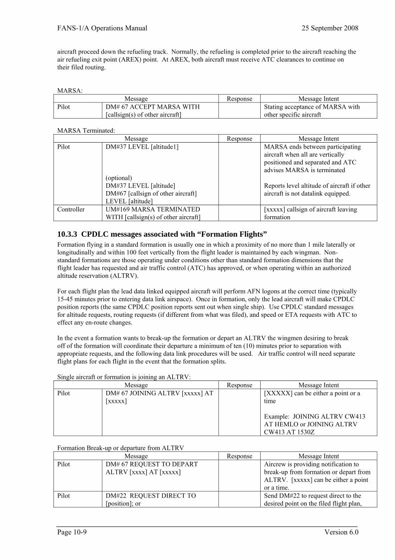
FANS-1/A Operations Manual 25 September 2008
aircraft proceed down the refueling track. Normally, the refueling is completed prior to the aircraft reaching the air refueling exit point (AREX) point. At AREX, both aircraft must receive ATC clearances to continue on their filed routing. MARSA:
Message Response Message Intent Pilot DM# 67 ACCEPT MARSA WITH
[callsign(s) of other aircraft] Stating acceptance of MARSA with
other specific aircraft� MARSA Terminated:
Message Response Message Intent Pilot DM#37 LEVEL [altitude1]
MARSA ends between participating aircraft when all are vertically positioned and separated and ATC advises MARSA is terminated (optional)
DM#37 LEVEL [altitude] Reports level altitude of aircraft if other aircraft is not datalink equipped. DM#67 [callsign of other aircraft]
LEVEL [altitude] Controller UM#169 MARSA TERMINATED
WITH [callsign(s) of other aircraft] [xxxxx] callsign of aircraft leaving
formation
10.3.3 CPDLC messages associated with “Formation Flights” Formation flying in a standard formation is usually one in which a proximity of no more than 1 mile laterally or longitudinally and within 100 feet vertically from the flight leader is maintained by each wingman. Non-standard formations are those operating under conditions other than standard formation dimensions that the flight leader has requested and air traffic control (ATC) has approved, or when operating within an authorized altitude reservation (ALTRV). For each flight plan the lead data linked equipped aircraft will perform AFN logons at the correct time (typically 15-45 minutes prior to entering data link airspace). Once in formation, only the lead aircraft will make CPDLC position reports (the same CPDLC position reports sent out when single ship). Use CPDLC standard messages for altitude requests, routing requests (if different from what was filed), and speed or ETA requests with ATC to effect any en-route changes. In the event a formation wants to break-up the formation or depart an ALTRV the wingmen desiring to break off of the formation will coordinate their departure a minimum of ten (10) minutes prior to separation with appropriate requests, and the following data link procedures will be used. Air traffic control will need separate flight plans for each flight in the event that the formation splits. Single aircraft or formation is joining an ALTRV:
Message Response Message Intent Pilot DM# 67 JOINING ALTRV [xxxxx] AT
[xxxxx] [XXXXX] can be either a point or a
time Example: JOINING ALTRV CW413 AT HEMLO or JOINING ALTRV CW413 AT 1530Z
Formation Break-up or departure from ALTRV
Message Response Message Intent Pilot DM# 67 REQUEST TO DEPART
ALTRV [xxxx] AT [xxxxx] Aircrew is providing notification to
break-up from formation or depart from ALTRV. [xxxxx] can be either a point or a time.
Pilot DM#22 REQUEST DIRECT TO [position]; or
Send DM#22 to request direct to the desired point on the filed flight plan,
Page 10-9 Version 6.0
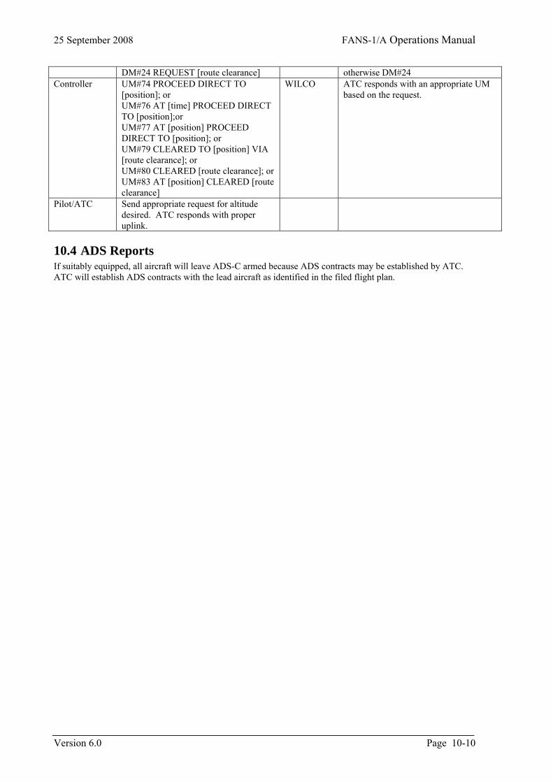
25 September 2008 FANS-1/A Operations Manual
Version 6.0 Page 10-10
DM#24 REQUEST [route clearance]� otherwise DM#24 Controller UM#74 PROCEED DIRECT TO
[position]; or UM#76 AT [time] PROCEED DIRECT TO [position];or UM#77 AT [position] PROCEED DIRECT TO [position]; or UM#79 CLEARED TO [position] VIA [route clearance]; or UM#80 CLEARED [route clearance]; or UM#83 AT [position] CLEARED [route clearance]
WILCO ATC responds with an appropriate UM based on the request.
Pilot/ATC Send appropriate request for altitude desired. ATC responds with proper uplink.
10.4 ADS Reports If suitably equipped, all aircraft will leave ADS-C armed because ADS contracts may be established by ATC. ATC will establish ADS contracts with the lead aircraft as identified in the filed flight plan.

FANS-1/A Operations Manual 25 September 2008
Page 11-1 Version 6.0
11 Endnotes 1 After many years of discussion and persuasion, the FOM is in a position to transition into a datalink document with truly worldwide acceptance, including the North Atlantic. This effort, to create the Global Operational Data Link Document (GOLD) is being guided by Tom Kraft and it makes sense to move the FOM editorship to him to ease coordination. 2 Takahiro Morishima has become the new FIT Co-chair for Japan. 3 RFC 08-005 Note that numbering has changed slightly for the manual form and the field descriptions for it. 4 RFC 08-001 5 RFC 08-002 6 RFC 08-002 7 RFC 08-002 8 RFC 08-003 9 RFC 08-004 10 RFC 08-009 11 RFC 08-013 12 RFC 08-012 13 The Japanese CRA and CRASA representatives have changed.