Embed Size (px)
Citation preview
HAL Id: hal-01110745https://hal.archives-ouvertes.fr/hal-01110745
Submitted on 29 Jan 2015
HAL is a multi-disciplinary open accessarchive for the deposit and dissemination of sci-entific research documents, whether they are pub-lished or not. The documents may come fromteaching and research institutions in France orabroad, or from public or private research centers.
L’archive ouverte pluridisciplinaire HAL, estdestinée au dépôt et à la diffusion de documentsscientifiques de niveau recherche, publiés ou non,émanant des établissements d’enseignement et derecherche français ou étrangers, des laboratoirespublics ou privés.
Very high cycle fatigue of a high strength steel undersea water corrosion: A strong corrosion and mechanical
damage couplingRuben Perez-Mora, Thierry Palin-Luc, Claude Bathias, Paul C. Paris
To cite this version:Ruben Perez-Mora, Thierry Palin-Luc, Claude Bathias, Paul C. Paris. Very high cycle fatigue of ahigh strength steel under sea water corrosion: A strong corrosion and mechanical damage coupling.International Journal of Fatigue, Elsevier, 2015, 74, pp.156-165. �10.1016/j.ijfatigue.2015.01.004�.�hal-01110745�
Very high cycle fatigue of a high strength steel under sea watercorrosion: A strong corrosion and mechanical damage coupling
Ruben Pérez-Mora a, Thierry Palin-Luc b,⇑, Claude Bathias a, Paul C. Paris c
a Universite Paris Ouest, LEME, 50 rue de Sevres, 92410 Ville d’Avray, Franceb Arts et Metiers ParisTech, I2M, CNRS, Universite de Bordeaux, Esplanade des Arts et Metiers, 33405 Talence Cedex, Francec Parks College of Engineering, Aviation and Technology, St. Louis University, St. Louis, MO 63103, USA
Keywords:Gigacycle fatigueCorrosionSteelCrack initiationCrack growth
a b s t r a c t
This paper is focused on the effect of sea water corrosion on the gigacycle fatigue strength of a martens-itic–bainitic hot rolled steel R5 used for manufacturing off-shore mooring chains for petroleum platformsin the North Sea. Crack initiation fatigue tests in the regime of 106 to 1010 cycles were carried out onsmooth specimens under three different environment conditions: (i) without any corrosion (virgin state)in air, (ii) in air after pre-corrosion, and (iii) in-situ corrosion-fatigue under artificial sea water flow. Adrastic effect of sea water corrosion was found: the median fatigue strength beyond 108 cycles is dividedby 5 compared to virgin state specimens. The crack initiation sites were corrosion pits caused by pre-corrosion or created during corrosion-fatigue under sea water flow. Furthermore some sub-surface andinternal crack initiations were observed on specimens without any corrosion (virgin state). Crackpropagation curves were obtained in mode I in air and under sea water flow. Calculation of the stressintensity factor at the tip of cracks emanating from hemispherical surface pits combined with theParis–Hertzberg–Mc Clintock crack growth rate model showed that fatigue crack initiation period repre-sents most of the fatigue life in the VHCF regime. Additional original experiments have shown physicalevidences that the fatigue strength in the gigacycle regime under sea water flow is mainly governedby the corrosion process with a strong coupling between cyclic loading and corrosion.
1. Introduction
The mooring chains of off-shore petroleum platforms aredesigned for 30 years and loaded in fatigue in corrosive environ-ment due to sea water. Because of the ocean waves (frequencyvarying between 0.1 and 1 Hz) 24 h a day, the number of loadcycles during 30 years is between 9.5 � 107 and 9.5 � 108 cyclesthat is in the gigacycle regime (more than 108 cycles). This studyis focused on the gigacycle fatigue strength of low alloy steel usedfor manufacturing such chains. The effect of pre-corrosion and realtime corrosion conditions on the fatigue strength and crack growthrate are investigated. It has been demonstrated by many studies onsteel and aluminum alloys in the gigacycle regime that there is nofatigue limit for such metals beyond 107 cycles as was believed inthe past [1,2]. Moreover, fatigue cracks initiate mainly at surfacedefects in the short fatigue life regime, but may shift to subsurfacein the long life range [3]. Some other studies have shown thatdefects like non-metallic inclusions, pores [4] or pits [5–7] are
the key factors that control the fatigue behavior of metals in veryhigh cycle fatigue (VHCF) regime. On the other hand, some studieshave been proving that crack initiation dominates the total fatiguelife of iron alloys in gigacycle fatigue in air [8,9]. Furthermore, theinfluence of static deformation has been studied confirming thatboth passive and transpassive current densities on stainless steelreach a maximum in the course of growing plastic strain [10].Other studies have investigated the dissolution under chemicalproducts on stainless steel with active, passive and intermediatepotentials where it is presumed that dissolution is enhancedduring cyclic loading [11]. But the effect of aqueous corrosion onthe fatigue strength with regard to crack initiation in the VHCFregime is not very much studied in literature [12]. In this regimethe material is loaded in its elastic domain at the macroscopicscale. In this study the effect of sea water corrosion (under freepotential) on the VHCF strength is studied.
After presenting the investigated material and the experimentalconditions both for crack initiation and crack propagation tests,experimental results are presented and discussed with regard toSEM observations of the fracture surface. It is shown that a drasticeffect of sea water corrosion decreases the fatigue strength of the
⇑ Corresponding author.E-mail address: [email protected] (T. Palin-Luc).

steel under sea water flow. The assessment of the crack growthhelps us to show that crack initiation dominates the total fatiguelife in the gigacycle regime. Furthermore, additional experimentsallow the authors to show experimental evidences of couplingbetween corrosion and cyclic loading even under ultrasonic load-ing frequency.
2. Material and experimental conditions
The material studied hereafter is a non-standard hot rolled lowalloy steel grade (named R5 according to the International Classifi-cation Societies of Off-shore Systems) with a typical fine grainmicrostructure, composed by tempered martensite and bainite,as shown in Fig. 1. Its chemical composition is shown in Table 1.This steel is used after a double quenching in water, a first periodat 920 �C and a second period at 880 �C and then tempering at650 �C with water cooling. After this heat treatment its mechanicalproperties are: hardness 317 HB, yield strength 970 MPa, ultimatetensile strength UTS = 1018 MPa, Young modulus E = 211 GPaunder monotonic quasi-static tension. It has to be noticed that thissteel is vacuum degassed with low hydrogen content (1 ppm max-imum in the liquid steel after the vacuum treatment). Furthermore,very low non-metallic inclusions are present in this steel (seedetails in [12]).
2.1. Fatigue test conditions and specimen geometry
2.1.1. Testing machine and specimen geometryAll the fatigue tests (crack initiation and crack growth) pre-
sented hereafter were carried out with an ultrasonic fatigue testing
machine [1] operating continuously at 20 kHz (no pulse loading)under fully reversed tension (R = �1) (see [1,12] for details).Fig. 2 shows the dimensions of the two types of specimens usedfor (a) VHCF crack initiation tests and (b) fatigue crack growth(FCG) tests. The geometry of the FCG specimens was designedaccording to the works of Wu [13] and Sun [14]. The crack growthwas measured with an optical binocular microscope equipped witha digital camera; this set up has a maximum magnification �200and a resolution of 0.5 lm. The roughness of the tested area ofthe VHCF specimens was Ra = 0.6 lm; additionally a few speci-mens with a lower arithmetic roughness (Ra = 0.1 lm) were testedtoo for investigating the effect of roughness. The VHCF specimenswere tested under three different conditions: (i) without any corro-sion (virgin state), (ii) after pre-corrosion and (iii) under real timeartificial sea water flow.
All the VHCF tests were calibrated by using a wide band(100 kHz) strain gauge conditioner and a longitudinal strain gaugeglued on the specimen surface. Such calibration allows the authorsto be certain of the local strain (elastic stress) amplitude and meanvalue in the narrowest cross section of the specimen. These testswere carried out until a decrease of the resonance frequency of0.5 kHz that indicates the presence of a macrocrack.
2.1.2. Corrosion of the specimensThe pre-corrosion of the specimens was done according to the
ASTM G85 standard: 600 h in a salt fog corrosion chamber undertemperature and humidity control (35 �C with 95% of humidity).The salt solution contains 5% of NaCl, its pH was 6.6 and it wasapplied in the chamber with a flow rate of 1.52 ml/h. After thepre-corrosion process the specimens were first chemically cleanedand then cleaned with emery paper to remove the oxide layer.Many corrosion pits were created by the salt fog (Fig. 3) whichdiameter is between 30 and 80 lm. These pits have hemisphericalshape and their depth can be compared with their radius. Compar-ing this dimension to prior austenite grain size, the pits are inbetween one and two times the size of the prior austenite grains.
To carry out VHCF tests in sea water environment a special cor-rosion cell was designed (see [12] for details). To avoid any cavita-tion it was decided to test the specimens under sea water flowwithout immersion. This is representative of the splash zone ofthe mooring chains. To do that a peristaltic pump creates a flowof sea water (100 ml/min) on two opposite sides of the specimensurface in the tested area (diameter 3 mm). The sea water usedwas the A3 standard synthetic sea water; its chemical composition
Nomenclature
a crack lengthaint crack length at initiationa0 crack length at the corner of the crack growth curve cor-
responding to the threshold DKth
b Burger vectorE Young’s modulusNf total number of cycles to failure including initiation and
propagation periodsNprop number of cycles of the crack propagation periodNai–a number of cycles of the long crack growth period
Nao–ai number of cycles of the small crack growth periodNaint–ao number of cycles of the short crack growth periodR radius of hemispherical surface defectU0 displacement amplitude at the extremity of the speci-
menw width of the crack growth specimenm Poisson ratioDK range of the stress intensity factorDKth range of the stress intensity factor at the thresholdra stress amplitude
Table 1Composition of R5 steel (wt%, Fe balance).
C Mn Si P S Cr Ni Mo V O
0.22 1.22 0.3 0.009 0.003 1.07 1.07 0.5 0.09 12 ppm
Fig. 1. R5 steel microstructure (after Nital etching 2%).
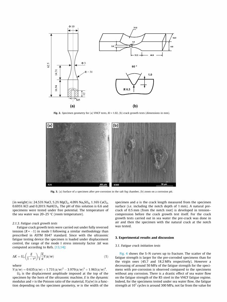
(in weight) is: 24.53% NaCl, 5.2% MgCl2, 4.09% Na2SO4, 1.16% CaCl2,0.695% KCl and 0.201% NaHCO3. The pH of this solution is 6.6 andspecimens were tested under free potential. The temperature ofthe sea water was 20–25 �C (room temperature).
2.1.3. Fatigue crack growth testsFatigue crack growth tests were carried out under fully reversed
tension (R = �1) in mode I following a similar methodology thanprescribed in ASTM E647 standard. Since with the ultrasonicfatigue testing device the specimen is loaded under displacementcontrol, the range of the mode I stress intensity factor DK wascomputed according to Refs. [13,14]:
DK ¼ UoE
1� m2
� � ffiffiffiffipa
rYða=wÞ ð1Þ
whereYða=wÞ ¼ 0:635ða=wÞ þ 1:731ða=wÞ2 � 3:979ða=wÞ3 þ 1:963ða=wÞ4.
U0 is the displacement amplitude imposed at the top of thespecimen by the horn of the ultrasonic machine, E is the dynamicmodulus and m is the Poisson ratio of the material, Y(a/w) is a func-tion depending on the specimen geometry, w is the width of the
specimen and a is the crack length measured from the specimensurface (i.e. including the notch depth of 1 mm). A natural pre-crack of 0.5 mm (from the notch root) is developed in tension–compression before the crack growth test itself. For the crackgrowth tests carried out in sea water the pre-crack was done inair and then the specimen with the natural crack at the notchwas tested.
3. Experimental results and discussion
3.1. Fatigue crack initiation tests
Fig. 4 shows the S–N curves up to fracture. The scatter of thefatigue strength is larger for the pre-corroded specimens than forthe virgin ones (45.7 and 18.2 MPa respectively). However adecreasing of around 50 MPa of the fatigue strength for the speci-mens with pre-corrosion is observed compared to the specimenswithout any corrosion. There is a drastic effect of sea water flowon the fatigue strength of the R5 steel in the VHCF fatigue regime.Indeed, for the specimens tested under sea water flow, the fatiguestrength at 107 cycles is around 300 MPa, not far from the value for
Fig. 2. Specimen geometry for (a) VHCF tests, Kt = 1.02, (b) crack growth tests (dimensions in mm).
Fig. 3. (a) Surface of a specimen after pre-corrosion in the salt fog chamber, (b) zoom on a corrosion pit.

pre-corroded specimens (360 MPa), but for 3 � 108 cycles the fati-gue strength is around 100 MPa only. That is a decrease of 74%compared to the non-corroded specimens (390 MPa) and adecrease of 71% compared to the pre-corroded ones (350 MPa).This shows that stopping the fatigue tests at 107 cycles and thenextrapolating the S–N curve may lead to a large overestimationof the corrosion-fatigue resistance.
The fatigue tests were carried out at 20 kHz under corrosiveenvironment and may be seen first as non-representative experi-ments because of the high loading frequency compared with thecharacteristic time of the corrosion process. However, it has beenshown by El May et al. [18] that the fatigue strength in tensionof a martensitic stainless steel in the high cycle fatigue regime(at 107 cycles) is significantly reduced by corrosion in 0.1 M NaClaqueous solution even at 120 Hz. Furthermore, these authors haveshown that there is no significant frequency effect between 10 and120 Hz between 105 and 107 cycles.
Our fatigue corrosion tests results (Fig. 4) show that the S–Ncurve of specimens tested under sea water flow crosses (around2–3 � 106 cycles) the S–N curve of virgin specimens (tested in airwithout any corrosion). This is not in agreement with a frequencyeffect but with the fact that a number of cyclic reversals (2 � N) areneeded to create corrosion fatigue defects and coupling as pro-posed in [18]. This will be discussed later in this paper.
3.2. SEM observation of the fracture surfaces
On virgin specimens, even if some unusual internal crack initi-ations were observed (Fig. 5), most of the fatigue cracks initiated atthe specimen surface over the cycle range (106–109 cycles). But forthis set of specimens no defect was observed in the crack initiationarea. Surface corrosion pits were the origins of the cracks for bothpre-corroded specimens and specimens tested under sea waterflow (Figs. 6 and 7). For the specimens tested under sea water flowthe cracks initiated all around the specimen surface due to severallarge corrosion pits. The size of the pits depends on the time (i.e.the number of cycles); their diameter is smaller on the pre-corroded specimens (30–80 lm) than under sea water flow(50–300 lm) (Figs. 6 and 7). Furthermore, a lot of small cracks,perpendicular to the loading direction (mode I), were observed at
the surface of the specimens tested under sea water flow, as shownin Fig. 7(c); whereas such small cracks were not observed on bothvirgin and pre-corroded specimens. This is characteristic of a corro-sion/cyclic loading interaction.
Since a significant decrease of the fatigue strength has beenobserved due to corrosion pits (seen as geometrical defects), it isimportant to determine if the crack propagation stage dominatesthe total fatigue life.
3.3. Assessment of the crack initiation and propagation duration
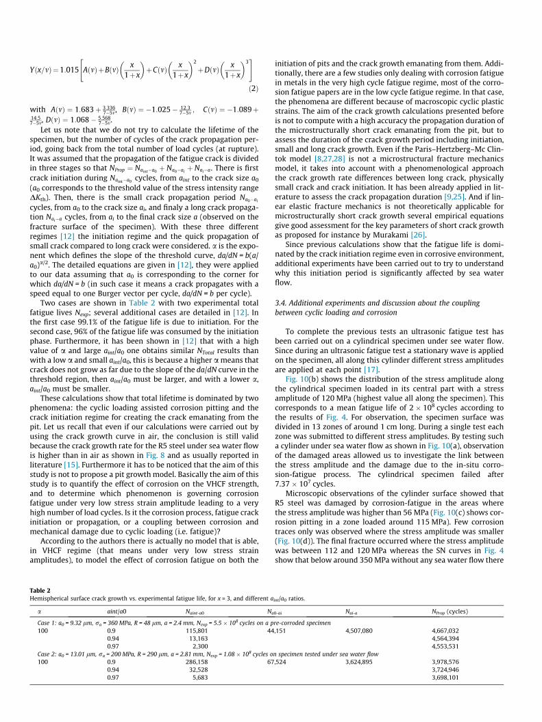
The experimental dadN ¼ f ðDKÞ curve is shown in Annex 1; this is
re-plotted as dadN ¼ f DKeff
Effiffibp
� �curve in Fig. 8. This shows that in air the
mode I stress intensity factor threshold for R5 steel is around3.3 MPa
pm for (R = �1). This value is between 2 and 10 MPa
pm
as reported for steels in Refs. [22,23]. As usual the crack growthrate is faster under sea water flow than in air [15]. The fatiguecrack propagation duration was assessed according to the workof Paris et al. [8,9], based on the Paris–Hertzberg–Mc Clintock crack
growth model: dadN ¼ b DKeff
Effiffibp
� �3and Keff
Effiffibp
� �¼ 1 at the corner (intersec-
tion between the Paris line and the threshold line), where E is theelastic modulus and b is the Burger’s vector. The good agreement ofthis equation with our experimental data and b = 0.285 nm wasshown in [12]. Since in our experiments at 20 kHz the measure-ment of Kop is not possible, in first approximation DKeff � Kmax
was assumed. We do not know if Kop is frequency dependent thatis why its value was not measured at low frequency and assumedto be the same at 20 kHz. Furthermore the authors assume thatwater present into the crack does not modify the value of the stressintensity factor. It is clear in Fig. 8 that since the crack growth ratein sea water is higher than in air; computing the crack growthduration based on the crack growth curve in air may only underes-timate this duration.
To assess this duration, a corrosion pit was not modeled as acrack-like defect but it was modeled as a hemispherical surfacedefect of radius R with a semi-circular crack emanating from it.The existence of these hemispherical pits was observed by scan-ning electron microscopy on the surface of different specimenswith pre-corrosion in salt fog chamber (Fig. 3) and after corrosion
Fig. 4. S–N curves of the R5 steel under fully reversed tension at 20 kHz.

Fig. 5. Fracture surface of R5 steel virgin specimens (a, c) internal crack initiation ra = 380 MPa, Nf = 2.78 � 106 cycles, (b, d) surface crack initiation ra = 395 MPa,Nf = 5.61 � 108 cycles.
Fig. 6. Specimen with pre-corrosion, ra = 425 MPa, Nf = 1.6 � 107 cycles.
Fig. 7. Specimen tested under sea water flow, ra = 240 MPa, Nf = 5.2 � 107 cycles.
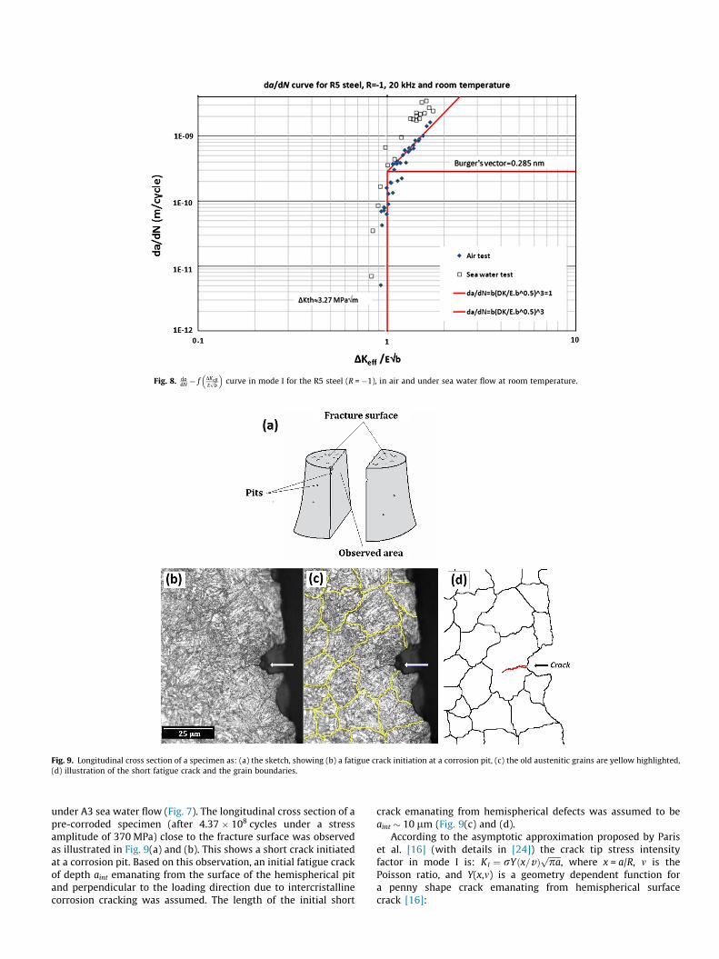
under A3 sea water flow (Fig. 7). The longitudinal cross section of apre-corroded specimen (after 4.37 � 108 cycles under a stressamplitude of 370 MPa) close to the fracture surface was observedas illustrated in Fig. 9(a) and (b). This shows a short crack initiatedat a corrosion pit. Based on this observation, an initial fatigue crackof depth aint emanating from the surface of the hemispherical pitand perpendicular to the loading direction due to intercristallinecorrosion cracking was assumed. The length of the initial short
crack emanating from hemispherical defects was assumed to beaint � 10 lm (Fig. 9(c) and (d).
According to the asymptotic approximation proposed by Pariset al. [16] (with details in [24]) the crack tip stress intensityfactor in mode I is: KI ¼ rYðx=vÞ
ffiffiffiffiffiffipap
, where x = a/R, m is thePoisson ratio, and Y(x,m) is a geometry dependent function fora penny shape crack emanating from hemispherical surfacecrack [16]:
Fig. 8. dadN ¼ f DKeff
Effiffibp
� �curve in mode I for the R5 steel (R = �1), in air and under sea water flow at room temperature.
Fig. 9. Longitudinal cross section of a specimen as: (a) the sketch, showing (b) a fatigue crack initiation at a corrosion pit, (c) the old austenitic grains are yellow highlighted,(d) illustration of the short fatigue crack and the grain boundaries.
Yðx=mÞ¼1:015 AðmÞþBðmÞ x1þx
� �þCðmÞ x
1þx
� �2
þDðmÞ x1þx
� �3" #
ð2Þ
with AðmÞ ¼ 1:683þ 3:3367�5m, BðmÞ ¼ �1:025� 12:3
7�5m ; CðmÞ ¼ �1:089þ14:57�5m, DðmÞ ¼ 1:068� 5:568
7�5m.Let us note that we do not try to calculate the lifetime of the
specimen, but the number of cycles of the crack propagation per-iod, going back from the total number of load cycles (at rupture).It was assumed that the propagation of the fatigue crack is dividedin three stages so that NProp ¼ Naint�a0 þ Na0�ai
þ Nai�a. There is firstcrack initiation during Naint�a0 cycles, from aint to the crack size a0
(a0 corresponds to the threshold value of the stress intensity rangeDKth). Then, there is the small crack propagation period Na0�ai
cycles, from a0 to the crack size ai, and finaly a long crack propaga-tion Nai�a cycles, from ai to the final crack size a (observed on thefracture surface of the specimen). With these three differentregimes [12] the initiation regime and the quick propagation ofsmall crack compared to long crack were considered. a is the expo-nent which defines the slope of the threshold curve, da/dN = b(a/a0)a/2. The detailed equations are given in [12], they were appliedto our data assuming that a0 is corresponding to the corner forwhich da/dN = b (in such case it means a crack propagates with aspeed equal to one Burger vector per cycle, da/dN = b per cycle).
Two cases are shown in Table 2 with two experimental totalfatigue lives Nexp; several additional cases are detailed in [12]. Inthe first case 99.1% of the fatigue life is due to initiation. For thesecond case, 96% of the fatigue life was consumed by the initiationphase. Furthermore, it has been shown in [12] that with a highvalue of a and large aint/a0 one obtains similar NTotal results thanwith a low a and small aint/a0, this is because a higher a means thatcrack does not grow as far due to the slope of the da/dN curve in thethreshold region, then aint/a0 must be larger, and with a lower a,aint/a0 must be smaller.
These calculations show that total lifetime is dominated by twophenomena: the cyclic loading assisted corrosion pitting and thecrack initiation regime for creating the crack emanating from thepit. Let us recall that even if our calculations were carried out byusing the crack growth curve in air, the conclusion is still validbecause the crack growth rate for the R5 steel under sea water flowis higher than in air as shown in Fig. 8 and as usually reported inliterature [15]. Furthermore it has to be noticed that the aim of thisstudy is not to propose a pit growth model. Basically the aim of thisstudy is to quantify the effect of corrosion on the VHCF strength,and to determine which phenomenon is governing corrosionfatigue under very low stress strain amplitude leading to a veryhigh number of load cycles. Is it the corrosion process, fatigue crackinitiation or propagation, or a coupling between corrosion andmechanical damage due to cyclic loading (i.e. fatigue)?
According to the authors there is actually no model that is able,in VHCF regime (that means under very low stress strainamplitudes), to model the effect of corrosion fatigue on both the
initiation of pits and the crack growth emanating from them. Addi-tionally, there are a few studies only dealing with corrosion fatiguein metals in the very high cycle fatigue regime, most of the corro-sion fatigue papers are in the low cycle fatigue regime. In that case,the phenomena are different because of macroscopic cyclic plasticstrains. The aim of the crack growth calculations presented beforeis not to compute with a high accuracy the propagation duration ofthe microstructurally short crack emanating from the pit, but toassess the duration of the crack growth period including initiation,small and long crack growth. Even if the Paris–Hertzberg–Mc Clin-tok model [8,27,28] is not a microstructural fracture mechanicsmodel, it takes into account with a phenomenological approachthe crack growth rate differences between long crack, physicallysmall crack and crack initiation. It has been already applied in lit-erature to assess the crack propagation duration [9,25]. And if lin-ear elastic fracture mechanics is not theoretically applicable formicrostructurally short crack growth several empirical equationsgive good assessment for the key parameters of short crack growthas proposed for instance by Murakami [26].
Since previous calculations show that the fatigue life is domi-nated by the crack initiation regime even in corrosive environment,additional experiments have been carried out to try to understandwhy this initiation period is significantly affected by sea waterflow.
3.4. Additional experiments and discussion about the couplingbetween cyclic loading and corrosion
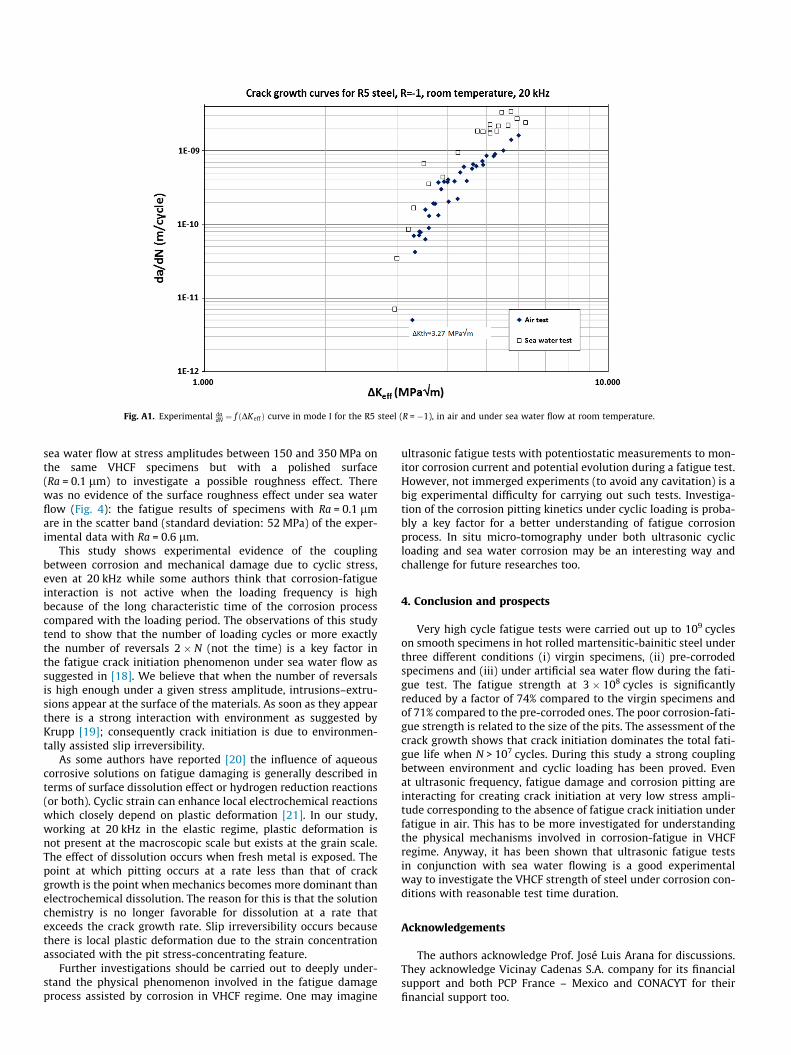
To complete the previous tests an ultrasonic fatigue test hasbeen carried out on a cylindrical specimen under see water flow.Since during an ultrasonic fatigue test a stationary wave is appliedon the specimen, all along this cylinder different stress amplitudesare applied at each point [17].
Fig. 10(b) shows the distribution of the stress amplitude alongthe cylindrical specimen loaded in its central part with a stressamplitude of 120 MPa (highest value all along the specimen). Thiscorresponds to a mean fatigue life of 2 � 108 cycles according tothe results of Fig. 4. For observation, the specimen surface wasdivided in 13 zones of around 1 cm long. During a single test eachzone was submitted to different stress amplitudes. By testing sucha cylinder under sea water flow as shown in Fig. 10(a), observationof the damaged areas allowed us to investigate the link betweenthe stress amplitude and the damage due to the in-situ corro-sion-fatigue process. The cylindrical specimen failed after7.37 � 107 cycles.
Microscopic observations of the cylinder surface showed thatR5 steel was damaged by corrosion-fatigue in the areas wherethe stress amplitude was higher than 56 MPa (Fig. 10(c) shows cor-rosion pitting in a zone loaded around 115 MPa). Few corrosiontraces only was observed where the stress amplitude was smaller(Fig. 10(d)). The final fracture occurred where the stress amplitudewas between 112 and 120 MPa whereas the SN curves in Fig. 4show that below around 350 MPa without any sea water flow there
Table 2Hemispherical surface crack growth vs. experimental fatigue life, for x = 3, and different aint/a0 ratios.
a aint/a0 Naint-a0 Na0-ai Nai-a NProp (cycles)
Case 1: a0 = 9.32 lm, ra = 360 MPa, R = 48 lm, a = 2.4 mm, Nexp = 5.5 � 108 cycles on a pre-corroded specimen100 0.9 115,801 44,151 4,507,080 4,667,032
0.94 13,163 4,564,3940.97 2,300 4,553,531
Case 2: a0 = 13.01 lm, ra = 200 MPa, R = 290 lm, a = 2.81 mm, Nexp = 1.08 � 108 cycles on specimen tested under sea water flow100 0.9 286,158 67,524 3,624,895 3,978,576
0.94 32,528 3,724,9460.97 5,683 3,698,101

was no failure after 2 � 108 cycles. This shows an experimentalevidence of the strong coupling between the corrosion processand cyclic loading in a wide range of stress amplitudes even atultrasonic frequency (20 kHz).
Furthermore, three additional tests were carried out on VHCFspecimens under the same conditions than all the other tests but,without any cyclic loading. Only the sea water flow was appliedon the specimen surface with the same flow rate than for the testswith cyclic loading. The aim of these tests was to quantify the cor-rosion damage (alone) after the same duration than 107 cycles(8 min 20 s at 20 kHz), 108 cycles (1 h 23 min 20 s at 20 kHz) and109 cycles (13 h 53 min 20 s at 20 kHz). No corrosion trace was
observed by SEM after 8mn20s. After 1 h 23 min 20 s only a fewtraces of corrosion appear but no pits were observed. Corrosionpits were observed at the specimen surface after 13h53mn20s.The typical size of these pits was varying between 30 and 60 lm(Fig. 11) this is significantly smaller than under simultaneous cyc-lic loading and sea water flow (Fig. 7). The same pit size wasobserved under sea water flow with a stress amplitude of240 MPa after 5 � 107 cycles. This corresponds to 42 mn only at20 kHz! This confirms that there is a coupling between corrosionand cyclic loading.
Because of such coupling, the question of the roughness effectoccurred. Complementary fatigue tests were carried out under
Fig. 10. (a) Schematic illustration of the test principle of a cylindrical specimen with constant cross section under sea water flow, (b) evolution of the stress amplitude alongthe longitudinal axis of the cylindrical specimen for a stress amplitude of 120 MPa in the central cross section, (c) and (d) optical picture of the specimen surface after7.37 � 107 cycles in area 8 and area 12 loaded at different stress amplitudes.
Fig. 11. Corrosion pits at the surface of a specimen under sea water flow during 13 h 53 min 20 s without any cyclic loading.
sea water flow at stress amplitudes between 150 and 350 MPa onthe same VHCF specimens but with a polished surface(Ra = 0.1 lm) to investigate a possible roughness effect. Therewas no evidence of the surface roughness effect under sea waterflow (Fig. 4): the fatigue results of specimens with Ra = 0.1 lmare in the scatter band (standard deviation: 52 MPa) of the exper-imental data with Ra = 0.6 lm.
This study shows experimental evidence of the couplingbetween corrosion and mechanical damage due to cyclic stress,even at 20 kHz while some authors think that corrosion-fatigueinteraction is not active when the loading frequency is highbecause of the long characteristic time of the corrosion processcompared with the loading period. The observations of this studytend to show that the number of loading cycles or more exactlythe number of reversals 2 � N (not the time) is a key factor inthe fatigue crack initiation phenomenon under sea water flow assuggested in [18]. We believe that when the number of reversalsis high enough under a given stress amplitude, intrusions–extru-sions appear at the surface of the materials. As soon as they appearthere is a strong interaction with environment as suggested byKrupp [19]; consequently crack initiation is due to environmen-tally assisted slip irreversibility.
As some authors have reported [20] the influence of aqueouscorrosive solutions on fatigue damaging is generally described interms of surface dissolution effect or hydrogen reduction reactions(or both). Cyclic strain can enhance local electrochemical reactionswhich closely depend on plastic deformation [21]. In our study,working at 20 kHz in the elastic regime, plastic deformation isnot present at the macroscopic scale but exists at the grain scale.The effect of dissolution occurs when fresh metal is exposed. Thepoint at which pitting occurs at a rate less than that of crackgrowth is the point when mechanics becomes more dominant thanelectrochemical dissolution. The reason for this is that the solutionchemistry is no longer favorable for dissolution at a rate thatexceeds the crack growth rate. Slip irreversibility occurs becausethere is local plastic deformation due to the strain concentrationassociated with the pit stress-concentrating feature.
Further investigations should be carried out to deeply under-stand the physical phenomenon involved in the fatigue damageprocess assisted by corrosion in VHCF regime. One may imagine
ultrasonic fatigue tests with potentiostatic measurements to mon-itor corrosion current and potential evolution during a fatigue test.However, not immerged experiments (to avoid any cavitation) is abig experimental difficulty for carrying out such tests. Investiga-tion of the corrosion pitting kinetics under cyclic loading is proba-bly a key factor for a better understanding of fatigue corrosionprocess. In situ micro-tomography under both ultrasonic cyclicloading and sea water corrosion may be an interesting way andchallenge for future researches too.
4. Conclusion and prospects
Very high cycle fatigue tests were carried out up to 109 cycleson smooth specimens in hot rolled martensitic-bainitic steel underthree different conditions (i) virgin specimens, (ii) pre-corrodedspecimens and (iii) under artificial sea water flow during the fati-gue test. The fatigue strength at 3 � 108 cycles is significantlyreduced by a factor of 74% compared to the virgin specimens andof 71% compared to the pre-corroded ones. The poor corrosion-fati-gue strength is related to the size of the pits. The assessment of thecrack growth shows that crack initiation dominates the total fati-gue life when N > 107 cycles. During this study a strong couplingbetween environment and cyclic loading has been proved. Evenat ultrasonic frequency, fatigue damage and corrosion pitting areinteracting for creating crack initiation at very low stress ampli-tude corresponding to the absence of fatigue crack initiation underfatigue in air. This has to be more investigated for understandingthe physical mechanisms involved in corrosion-fatigue in VHCFregime. Anyway, it has been shown that ultrasonic fatigue testsin conjunction with sea water flowing is a good experimentalway to investigate the VHCF strength of steel under corrosion con-ditions with reasonable test time duration.
Acknowledgements
The authors acknowledge Prof. José Luis Arana for discussions.They acknowledge Vicinay Cadenas S.A. company for its financialsupport and both PCP France – Mexico and CONACYT for theirfinancial support too.
Fig. A1. Experimental dadN ¼ f ðDKeff Þ curve in mode I for the R5 steel (R = �1), in air and under sea water flow at room temperature.

Appendix A
Annex 1: Experimental crack growth data (see Fig. A1).
References
[1] Bathias C, Paris PC. Gigacycle fatigue in mechanical practice. New YorkUSA: Marcel Dekker Publisher Co.; 2005.
[2] Marines I, Bin X, Bathias C. An Understanding of very high cycle fatigue ofmetals. Int J Fatigue 2003;25:1101–7.
[3] Zuo JH, Wang Z, Han H. Effect of microstructure on ultra-high cycle fatiguebehavior of Ti-6Al-4V. Mat Sci Eng A 2008;473:147–52.
[4] Ammar HR, Samuel AM, Samuel FH. Effect of casting imperfections on thefatigue life of 319-F and A356–T6 Al-Si alloys. Mater Sci Eng A2008;473:65–75.
[5] Pang HT, Reed PAS. Microstructure effects on high temperature fatigue crackinitiation and short crack growth in turbine disc nickel-base superalloy Udimet720 Li. Mater Sci Eng, A 2007;448:67–9.
[6] Yeske RA, Roth LD. Environmental effects on fatigue of stainless steel at veryhigh frequencies. In: Wells (Westinghouse), Buck JM, Tien Roth, editors.Ultrasonic fatigue. New York, USA: The Metallurgical Society of AIME; 1982. p.365–85.
[7] Ebara R, Yamada Y. Corrosion fatigue behaviour of 13Cr stainless steel and Ti–6Al–4V at ultrasonic frequency. In: Wells (Westinghouse), Buck JM, Tien Roth,editors. Ultrasonic fatigue. New York, USA: The Metallurgical Society of AIME;1982. p. 349–64.
[8] Paris PC. The relationship of effective stress intensity, elastic modulus andBurgers-vector on fatigue crack growth as associated with fish-eye gigacyclefatigue phenomena, In: Proceedings of VHCF-3, Kyoto, Japan, 2004, p. 1–13.
[9] Marines I, Paris PC, Tada H, Bathias C. Fatigue crack growth from small to longcracks in VHCF with surface initiations. Int J Fatigue 2007;29:2072–8.
[10] Gutman EM, Soloviof G. The mechanochemical behavior of type 316L stainlesssteel. Corros Sci 1996;38:1141–5.
[11] Pyle T, Rollins V, Howard D. The influence of cyclic plastic strain on thetransient dissolution behavior of 18/8 stainless steel in 3.7M H2SO4. JElectrochem Soc 1975;122:1445–53.
[12] Palin-Luc T, Perez-Mora R, Bathias C, Dominguez G, Paris PC, Arana JL. Fatiguecrack initiation and growth on a steel in the very high cycle fatigue regimewith sea water corrosion. Eng Fract Mech 2010;77:1953–62.
[13] Wu TY, Bathias C. Application of fracture mechanics concepts in ultrasonicfatigue. Eng Fract Mech 1994;47:683–90.
[14] Sun (2000); Etude du seuil de fissuration à haute fréquence en fatigue et enfretting fatigue. Ph.D. Thesis, CNAM, Paris France.
[15] Bathias C, Pineau A. Fatigue of materials and structures. ISTE Ltd and JohnWiley & Sons Inc; 2010. p. 512.
[16] Paris PC, Palin-Luc T, Tada H, Saintier, N. Stresses and crack tip stress intensityfactors around spherical and cylindrical voids and inclusions of differentelastic properties and with misfit sizes, In Proceedings Int. Crack Path, ESIS Ed.,Vicenza, Italy; 23–25 September 2009: 485–502.
[17] Stanzl-Tschegg S, Mughrabi H, Schoenbauer B. Life time and cyclic slip ofcopper in the VHCF regime. Int J Fatigue 2007;29:2050–9.
[18] El May M, Palin-Luc T, Saintier N, Devos O. Effect of corrosion on the high cyclefatigue strength of martensitic stainless steel X12CrNiMoV12-3. Int J Fatigue2013;47:330–9.
[19] Krupp U. Fatigue crack propagation in metals and alloys. Weinheim: Wiley-VHC Verlag GmbH & Co.; 2007. ISBN: 978-3-527-31537-6.
[20] Magnin T, Lardon JM. The influence of a 3.5% NaCl solution on the fatiguedamage evolution in a planar slip f.c.c. stainless steel. Mater Sci Eng1985;76:7–10.
[21] Patel C. Cyclic strain enhanced dissolution behavior of mild steel in 10 pctNH4NO3 and the correlation with corrosion fatigue properties. Metall Trans A1980;11:301–6.
[22] Halidun-Kelestmur M, Chaki T. The effect of various atmospheres on thethreshold fatigue crack growth behavior of AISI 304 stainless steel. Int J Fatigue2001;23:169–74.
[23] Steinbock J, Gudladt H-J. More insights into fatigue crack growth fromexperiments on steels and aluminium alloys – thresholds. Mater Sci Eng A2011;528:1296–301.
[24] Tada H, Paris PC, Irwin GR. The stress analysis of cracks handbook. 3rded. ASME; 2000 [details in appendix 1].
[25] Bathias C, Paris PC. Gigacycle fatigue of metallic aircraft components. Int JFatigue 2010;32:894–7.
[26] Murakami Y. Metal Fatigue: Effect of Small Defects and Non-MetallicInclusions. Elsevier Ed.; 2002.
[27] Hertzberg RW. Deformation and fracture mechanics of engineeringmaterials. New York: John Wiley; 1996.
[28] Paris PC, Tada H, Donald JK. Service load fatigue damage – a historicalperspective. Int J Fatigue 1999;21:S35–46.