Embed Size (px)
Citation preview
CV-SERIESVIBRATOR MOTOR
OPERATION AND PARTS MANUAL
Revision #1 (06/13/07)
P/N 36686LUL
MODEL CV-1MODEL CV-2MODEL CV-2EMODEL CV-3MODEL CV-3E
THIS MANUAL MUST ACCOMPANY THE EQUIPMENT AT ALL TIMES.
To find the latest revision of thispublication, visit our website at:
www.multiquip.com
Engine exhaust and some ofits constituents, and some dust created
of California to cause cancer, birthdefects and other reproductive harm.
by power sanding, sawing, grinding,drillingandotherconstructionactivitiescontains chemicals known to the State
Some examples of these chemicals are:
Leadfromlead-basedpaints.Crystallinesilicafrombricks.Cementandothermasonryproducts.Arsenicandchromiumfromchemicallytreatedlumber.
Your risk from these exposures varies,dependingonhowoftenyoudothistypeof work. To reduce your exposure tothese chemicals: work in aALWAYSwell ventilated area, and work withapproved safety equipment, such asdust masks that are specially designedto filter out microscopic particles.
CV-SERIES — PROPOSITION 65 WARNING
CV-SERIES • VIBRATOR MOTOR — PARTS AND OPERATION MANUAL — REV. #1 (06/13/07) — PAGE 3
Grinding/cutting/drilling of masonry, concrete, metal andother materials with silica in their composition may giveoff dust or mists containing crystalline silica. Silica is abasic component of sand, quartz, brick clay, granite andnumerous other minerals and rocks. Repeated and/orsubstantial inhalation of airborne crystalline silica cancause serious or fatal respiratory diseases, includingsilicosis. In addition, California and some otherauthorities have listed respirable crystalline silica as asubstance known to cause cancer. When cutting suchmaterials, always follow the respiratory precautionsmentioned above.
WARNING
Grinding/cutting/drilling of masonry, concrete, metal andother materials can generate dust, mists and fumescontaining chemicals known to cause serious or fatalinjury or illness, such as respiratory disease, cancer,birth defects or other reproductive harm. If you areunfamiliar with the risks associated with the particularprocess and/or material being cut or the composition ofthe tool being used, review the material safety datasheet and/or consult your employer, the materialmanufacturer/supplier, governmental agencies such asOSHA and NIOSH and other sources on hazardousmaterials. California and some other authorities, forinstance, have published lists of substances known tocause cancer, reproductive toxicity, or other harmfuleffects.
Control dust, mist and fumes at the source wherepossible. In this regard use good work practices andfollow the recommendations of the manufacturers orsuppliers, OSHA/NIOSH, and occupational and tradeassociations. Water should be used for dustsuppression when wet cutting is feasible. When thehazards from inhalation of dust, mists and fumes cannotbe eliminated, the operator and any bystanders shouldalways wear a respirator approved by NIOSH/MSHA forthe materials being used.
WARNING
SILICOSIS WARNING RESPIRATORY HAZARDS
CV-SERIES — SILICOSIS/ RESPIRATORY WARNINGS
PAGE 4 — STR 31VCV-SERIES • VIBRATOR MOTOR — PARTS AND OPERATION MANUAL — REV. #1 (06/13/07) — PAGE 4
CV-SERIES — TABLE OF CONTENTS
Specifications and part numbersare subject to change withoutnotice.
NOTE
MQ MULTIQUIP — CV-SERIESVIBRATOR MOTOR
Proposition 65 Warning ............................................. 2Silicosis/Respiratory Warnings .................................. 3Table of Contents ...................................................... 4Parts Ordering Procedures ....................................... 5Safety Message Alert Symbols ................................. 6Rules For Safe Operation ...................................... 7-9Specifications .......................................................... 10Decals ..................................................................... 11Preparation ............................................................. 12Operation ................................................................ 13Maintenance ...................................................... 14-16Troubleshooting ...................................................... 17Vibrator Motor Housing ...................................... 18-19Vibrator Motor Assembly ................................... 20-21
Terms and Conditions of Sale ................................. 22
CV-SERIES • VIBRATOR MOTOR — PARTS AND OPERATION MANUAL — REV. #1 (06/13/07) — PAGE 5
PARTS ORDERING PROCEDURES
ww
w.m
ultiq
uip
.com
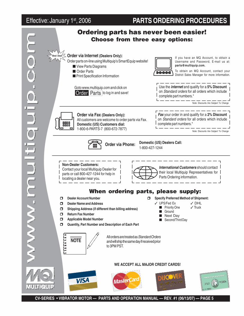
Ordering parts has never been easier!Choose from three easy options:
WE ACCEPT ALL MAJOR CREDIT CARDS!
When ordering parts, please supply:❒❒❒❒❒ Dealer Account Number
❒❒❒❒❒ Dealer Name and Address
❒❒❒❒❒ Shipping Address (if different than billing address)
❒❒❒❒❒ Return Fax Number❒❒❒❒❒ Applicable Model Number
❒❒❒❒❒ Quantity, Part Number and Description of Each Part
❒❒❒❒❒ Specify Preferred Method of Shipment:✓ UPS/Fed Ex ✓ DHL
■ Priority One ✓ Truck■ Ground■ Next Day■ Second/Third Day
All orders are treated as Standard Ordersand will ship the same day if received priorto 3PM PST.
If you have an MQ Account, to obtain aUsername and Password, E-mail us at:[email protected].
To obtain an MQ Account, contact yourDistrict Sales Manager for more information.
Order via Internet (Dealers Only):Order parts on-line using Multiquip’s SmartEquip website!
■ View Parts Diagrams■ Order Parts■ Print Specification Information
Note: Discounts Are Subject To Change
Goto www.multiquip.com and click on
Order Parts to log in and save!
Use the internet and qualify for a 5% Discounton Standard orders for all orders which includecomplete part numbers.*
Order via Fax (Dealers Only):All customers are welcome to order parts via Fax.Domestic (US) Customers dial:1-800-6-PARTS-7 (800-672-7877)
Fax your order in and qualify for a 2% Discounton Standard orders for all orders which includecomplete part numbers.*
Order via Phone: Domestic (US) Dealers Call:1-800-427-1244
Best Deal!
International Customers should contacttheir local Multiquip Representatives forParts Ordering information.
Non-Dealer Customers:Contact your local Multiquip Dealer forparts or call 800-427-1244 for help inlocating a dealer near you.
Note: Discounts Are Subject To Change
NOTE
Effective: January 1st, 2006
PAGE 6 — STR 31VCV-SERIES • VIBRATOR MOTOR — PARTS AND OPERATION MANUAL — REV. #1 (06/13/07) — PAGE 6
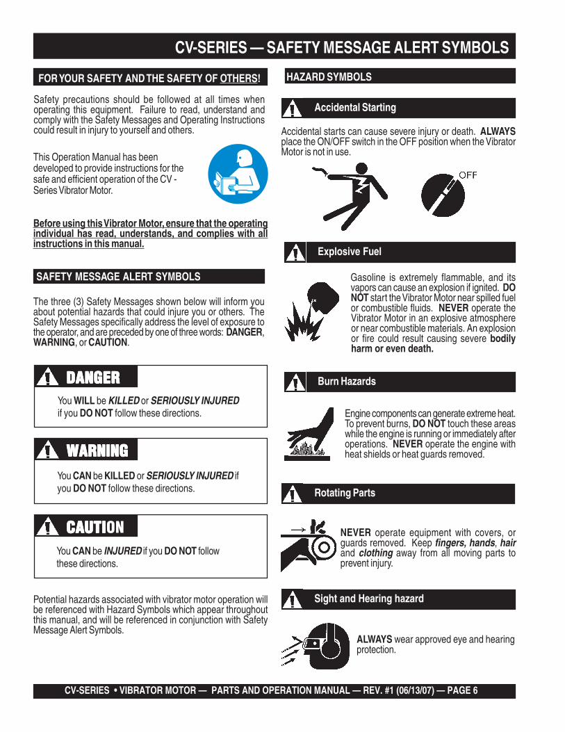
Accidental Starting
ALWAYS wear approved eye and hearingprotection.
Sight and Hearing hazard
CV-SERIES — SAFETY MESSAGE ALERT SYMBOLS
Accidental starts can cause severe injury or death. ALWAYSplace the ON/OFF switch in the OFF position when the VibratorMotor is not in use.
HAZARD SYMBOLS
Gasoline is extremely flammable, and itsvapors can cause an explosion if ignited. DONOT start the Vibrator Motor near spilled fuelor combustible fluids. NEVER operate theVibrator Motor in an explosive atmosphereor near combustible materials. An explosionor fire could result causing severe bodilyharm or even death.
Explosive Fuel
Burn Hazards
Engine components can generate extreme heat.To prevent burns, DO NOT touch these areaswhile the engine is running or immediately afteroperations. NEVER operate the engine withheat shields or heat guards removed.
Rotating Parts
NEVER operate equipment with covers, orguards removed. Keep fingers, hands, hairand clothing away from all moving parts toprevent injury.
Safety precautions should be followed at all times whenoperating this equipment. Failure to read, understand andcomply with the Safety Messages and Operating Instructionscould result in injury to yourself and others.
FOR YOUR SAFETY AND THE SAFETY OF OTHERS!
Before using this Vibrator Motor, ensure that the operatingindividual has read, understands, and complies with allinstructions in this manual.
SAFETY MESSAGE ALERT SYMBOLS
The three (3) Safety Messages shown below will inform youabout potential hazards that could injure you or others. TheSafety Messages specifically address the level of exposure tothe operator, and are preceded by one of three words: DANGER,WARNING, or CAUTION.
You WILL be KILLED or SERIOUSLY INJUREDif you DO NOT follow these directions.
You CAN be KILLED or SERIOUSLY INJURED ifyou DO NOT follow these directions.
You CAN be INJURED if you DO NOT followthese directions.
CAUTICAUTICAUTICAUTICAUTION
DANGERDANGERDANGERDANGERDANGER
WARNINGWARNINGWARNINGWARNINGWARNING
Potential hazards associated with vibrator motor operation willbe referenced with Hazard Symbols which appear throughoutthis manual, and will be referenced in conjunction with SafetyMessage Alert Symbols.
This Operation Manual has beendeveloped to provide instructions for thesafe and efficient operation of the CV -Series Vibrator Motor.
CV-SERIES • VIBRATOR MOTOR — PARTS AND OPERATION MANUAL — REV. #1 (06/13/07) — PAGE 7
CV-SERIES — RULES FOR SAFE OPERATION
GENERAL SAFETY RULES
■ DO NOT operate or service thisequipment before you read, understand,and comply with all safety messages inthis manual. The manual must be keptavailable and accessible to the operator.
RULES FOR SAFE OPERATION
■ ALWAYS check the vibrator motor for loosened hardwaresuch as nuts and bolts before starting.
■ Replace nameplate, operation and safety decals when theybecome difficult to read.
■ NEVER use accessories or attachments which are notrecommended by the manufacturer for this equipment.Damage to the equipment and/or injury to user may result.
WARNINGWARNINGWARNINGWARNINGWARNINGFailure to follow instructions in this manual may lead to seriousinjury or even death! This equipment is to be operated bytrained and qualified personnel only! This equipment is forindustrial use only.
■ NEVER operate a vibrator motor while under the influence ofdrugs, alcohol, or medications that may impair the senses orreactions.
■ NEVER use this machine for any purpose other than thosedescribed in this manual.
■ This equipment should not be operated by persons underthe minimum statutory age limit.
The following safety guidelines should always be used whenoperating the CV-SERIES Vibrator Motor.
VIBRATOR MOTOR OPERATION SAFETY RULES
■ Dress properly. Wear appropriate clothing and protectivesafety equipment. Wear clothing that will not likely becomecaught in the equipment or snag on the forms. Eye, hand,hearing, and foot safety equipment is required.
■ Manufacturer does not assume responsibility for any accidentdue to equipment modifications. Unauthorized equipmentmodification will void all warranties. Any modification whichcould lead to a change in the original characteristics of themachine should be made only by the manufacturer who shallconfirm that the machine is in conformity with appropriatesafety regulations.
■ Keep untrained personnel away. DO NOT let visitors contactthe vibrator unit. All visitors should be kept away from thework area.
■ Keep work area well lit.
■ Keep work area clean and well organized. A cluttered areainvites injuries.
■ ALWAYS clear the work area of any debris, tools, etc. thatwould constitute a hazard while the vibrator motor is inoperation.
■ ALWAYS be sure the operator is familiar with proper safetyprecautions and operations techniques before using vibratormotor.
■ DO NOT overreach. Keep proper footing and balance at alltimes.
■ Secure forms. Make sure the form work is well made andbraced to withstand the stresses made by vibration.
■ Keep vibrator motor clean for better and safer operation.
■ Inspect motor cord periodically and if damaged, have itrepaired by an authorized service facility.
■ Before each use ALWAYS check the motor to make certainthere are no damaged parts, and that all parts functionproperly, (examples: switch, cord housing). If any damage ormalfunctioning parts are found, have them repaired orreplaced by an authorized service facility.
■ Use only factory authorized identical replacement parts.
■ Always observe all applicable compulsory regulationsrelevant to environmental protection, especially, fuel storage,the handling of hazardous substances, and the wearing ofprotective clothing and equipment. Instruct the user asnecessary, or, as the user, request this information andtraining.
PAGE 8 — STR 31VCV-SERIES • VIBRATOR MOTOR — PARTS AND OPERATION MANUAL — REV. #1 (06/13/07) — PAGE 8
CV-SERIES — RULES FOR SAFE OPERATION
■ ALWAYS keep clear of rotating or moving parts whileoperating the vibrator motor.
■ NEVER leave the machine unattended while running.
■ ALWAYS turn the motor off and unplug the power cord beforeperforming service or maintenance functions.
■ DO NOT yank the cord to disconnect it from the receptacle.Grasp the plug itself to disconnect it.
■ Allow the vibrator motor to cool before servicing.Contact with hot! components can causeserious burns.
■ NEVER operate the vibrator motor inan explosive atmosphere wherefumes are present, or nearcombustible materials. An explosion orfire could result in severe bodily harmor even death.
■ ALWAYS disconnect the motor from the power source whennot in use, before servicing, and when changing flexibleshafting and vibrator heads.
■ Before plugging the motor into a power source, ALWAYSremove any wrenches or other tools from the motor, shaft,and head that were used for assembly.
■ NEVER carry the motor by the cord. Use the carrying frame.
■ Keep the cord from heat, oil, and sharp objects.
■ DO NOT overload the motor. It will do a better and safer jobat the rate for which it was designed.
■ DO NOT force the motor and head to do the job of a largermotor and head.
■ DO NOT expose vibrator motor to rain.
■ DO NOT use vibrator motor in damp or wet locations withoutproper electrical circuits.
■ Be sure switch is in the "OFF" position before plugging themotor into a power source.
■ DO NOT carry plugged-in motor with finger on the switch.
■ Store idle vibrator motor. When not in use, motor should bestored in a dry, safe storage area.
■ NEVER use the motor with a defective switch. If the switchdoes not turn the motor "ON" or "OFF", have it replaced beforeusing the motor.
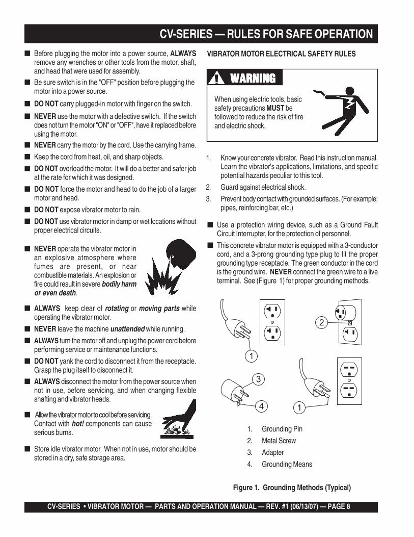
VIBRATOR MOTOR ELECTRICAL SAFETY RULES
1. Know your concrete vibrator. Read this instruction manual.Learn the vibrator's applications, limitations, and specificpotential hazards peculiar to this tool.
2. Guard against electrical shock.
3. Prevent body contact with grounded surfaces. (For example:pipes, reinforcing bar, etc.)
WARNINGWARNINGWARNINGWARNINGWARNING
When using electric tools, basicsafety precautions MUST befollowed to reduce the risk of fireand electric shock.
■ Use a protection wiring device, such as a Ground FaultCircuit Interrupter, for the protection of personnel.
■ This concrete vibrator motor is equipped with a 3-conductorcord, and a 3-prong grounding type plug to fit the propergrounding type receptacle. The green conductor in the cordis the ground wire. NEVER connect the green wire to a liveterminal. See (Figure 1) for proper grounding methods.
Figure 1. Grounding Methods (Typical)
1. Grounding Pin
2. Metal Screw
3. Adapter
4. Grounding Means
2
4 1
3
1
CV-SERIES • VIBRATOR MOTOR — PARTS AND OPERATION MANUAL — REV. #1 (06/13/07) — PAGE 9
CV-SERIES — RULES FOR SAFE OPERATION
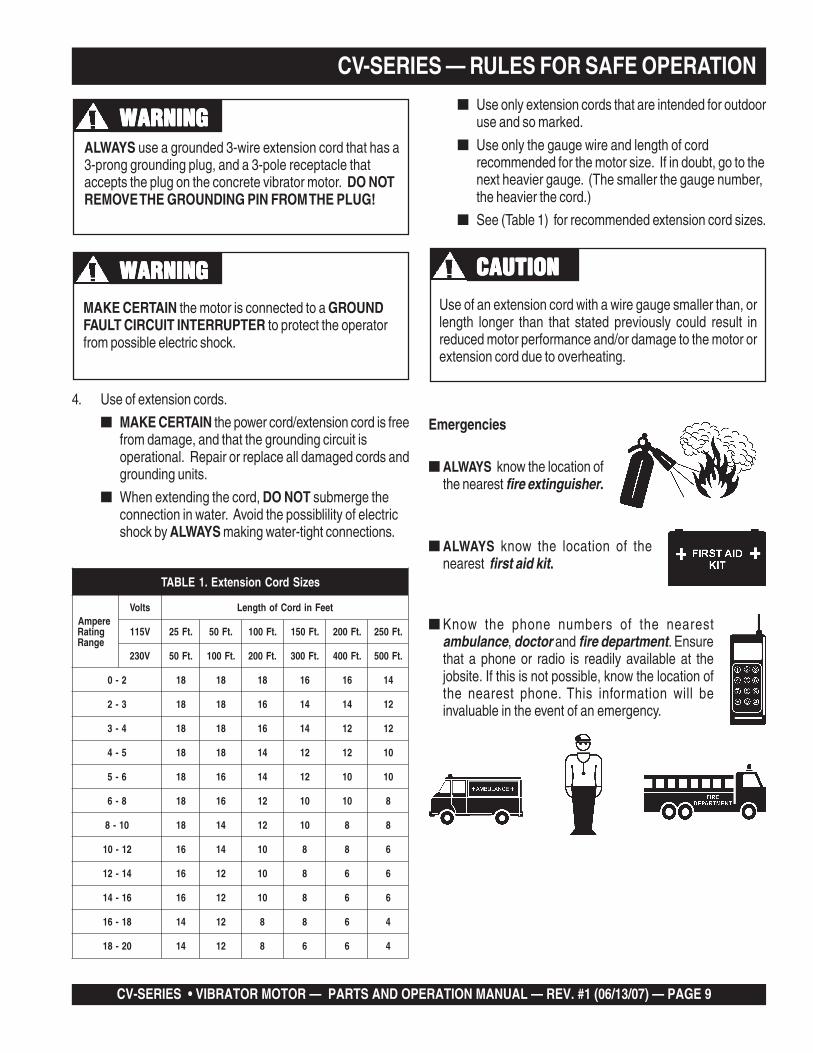
ALWAYS use a grounded 3-wire extension cord that has a3-prong grounding plug, and a 3-pole receptacle thataccepts the plug on the concrete vibrator motor. DO NOTREMOVE THE GROUNDING PIN FROM THE PLUG!
WARNINGWARNINGWARNINGWARNINGWARNING
WARNINGWARNINGWARNINGWARNINGWARNINGMAKE CERTAIN the motor is connected to a GROUNDFAULT CIRCUIT INTERRUPTER to protect the operatorfrom possible electric shock.
4. Use of extension cords.
■ MAKE CERTAIN the power cord/extension cord is freefrom damage, and that the grounding circuit isoperational. Repair or replace all damaged cords andgrounding units.
■ When extending the cord, DO NOT submerge theconnection in water. Avoid the possiblility of electricshock by ALWAYS making water-tight connections.
■ Use only extension cords that are intended for outdooruse and so marked.
■ Use only the gauge wire and length of cordrecommended for the motor size. If in doubt, go to thenext heavier gauge. (The smaller the gauge number,the heavier the cord.)
■ See (Table 1) for recommended extension cord sizes.
seziSdroCnoisnetxE.1ELBAT
erepmAgnitaRegnaR
stloV teeFnidroCfohtgneL
V511 .tF52 .tF05 .tF001 .tF051 .tF002 .tF052
V032 .tF05 .tF001 .tF002 .tF003 .tF004 .tF005
2-0 81 81 81 61 61 41
3-2 81 81 61 41 41 21
4-3 81 81 61 41 21 21
5-4 81 81 41 21 21 01
6-5 81 61 41 21 01 01
8-6 81 61 21 01 01 8
01-8 81 41 21 01 8 8
21-01 61 41 01 8 8 6
41-21 61 21 01 8 6 6
61-41 61 21 01 8 6 6
81-61 41 21 8 8 6 4
02-81 41 21 8 6 6 4
CAUTIONCAUTIONCAUTIONCAUTIONCAUTION
Emergencies
■ ALWAYS know the location of thenearest first aid kit.
■ Know the phone numbers of the nearestambulance, doctor and fire department. Ensurethat a phone or radio is readily available at thejobsite. If this is not possible, know the location ofthe nearest phone. This information will beinvaluable in the event of an emergency.
■ ALWAYS know the location ofthe nearest fire extinguisher.
Use of an extension cord with a wire gauge smaller than, orlength longer than that stated previously could result inreduced motor performance and/or damage to the motor orextension cord due to overheating.
PAGE 10 — STR 31VCV-SERIES • VIBRATOR MOTOR — PARTS AND OPERATION MANUAL — REV. #1 (06/13/07) — PAGE 10
CV-SERIES— SPECIFICATIONS (VIBRATOR MOTOR)
Figure 2. Dimensions
SNOITACIFICEPS.2ELBAT
ledoM 1-VC E2-VC/2-VC E3-VC/3-VC
rewopesroH )Wk647.0(PH1 )Wk294.1(PH2 )Wk832.2(PH3
htgneL )mm343("5.31 )mm343("5.31 )mm343("5.31
htdiW )mm52.222("57.8 )mm52.222("57.8 )mm52.222("57.8
thgieH )mm58.691("57.7 )mm58.691("57.7 )mm58.691("57.7
thgieW )g5.9894(.SBL11 )g9.9665(.SBL5.21 )g5.3216(.SBL5.31
)daoLoN(MPR MPR000,22 MPR000,22 MPR000,22
stloV CAV511 CAV511 CAV032 CAV511 CAV032
spmA A01 A51 A5.7 A02 A01
ztreH zH06/05 zH06/05 zH06/05
CV-SERIES • VIBRATOR MOTOR — PARTS AND OPERATION MANUAL — REV. #1 (06/13/07) — PAGE 11
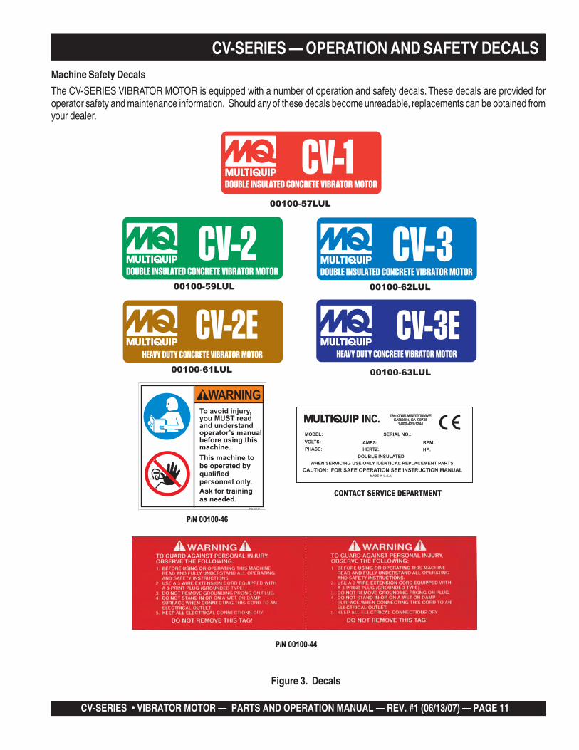
CV-SERIES — OPERATION AND SAFETY DECALSMachine Safety Decals
The CV-SERIES VIBRATOR MOTOR is equipped with a number of operation and safety decals. These decals are provided foroperator safety and maintenance information. Should any of these decals become unreadable, replacements can be obtained fromyour dealer.
Figure 3. Decals
P/N 00100-44
P/N 36676
P/N 00100-46
CONTACT SERVICE DEPARTMENT
NC.
00100-57LUL
00100-59LUL
00100-61LUL
00100-62LUL
00100-63LUL
PAGE 12 — STR 31VCV-SERIES • VIBRATOR MOTOR — PARTS AND OPERATION MANUAL — REV. #1 (06/13/07) — PAGE 12
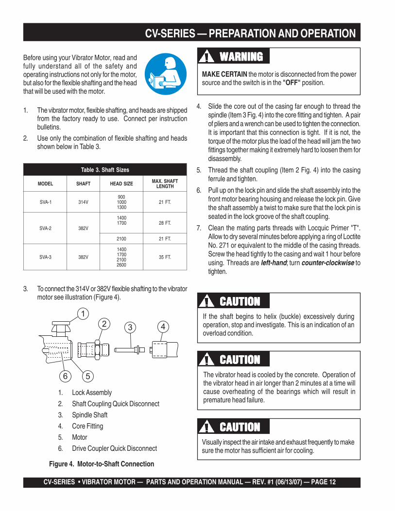
CV-SERIES — PREPARATION AND OPERATION
1. The vibrator motor, flexible shafting, and heads are shippedfrom the factory ready to use. Connect per instructionbulletins.
2. Use only the combination of flexible shafting and headsshown below in Table 3.
Before using your Vibrator Motor, read andfully understand all of the safety andoperating instructions not only for the motor,but also for the flexible shafting and the headthat will be used with the motor.
3. To connect the 314V or 382V flexible shafting to the vibratormotor see illustration (Figure 4).
MAKE CERTAIN the motor is disconnected from the powersource and the switch is in the "OFF" position.
If the shaft begins to helix (buckle) excessively duringoperation, stop and investigate. This is an indication of anoverload condition.
The vibrator head is cooled by the concrete. Operation ofthe vibrator head in air longer than 2 minutes at a time willcause overheating of the bearings which will result inpremature head failure.
Visually inspect the air intake and exhaust frequently to makesure the motor has sufficient air for cooling.
WARNINGWARNINGWARNINGWARNINGWARNING
CAUTIONCAUTIONCAUTIONCAUTIONCAUTION
CAUTIONCAUTIONCAUTIONCAUTIONCAUTION
CAUTIONCAUTIONCAUTIONCAUTIONCAUTION
Figure 4. Motor-to-Shaft Connection
seziStfahS.3elbaT
LEDOM TFAHS EZISDAEH TFAHS.XAMHTGNEL
1-AVS V41300900010031
.TF12
2-AVS V283
00410071 .TF82
0012 .TF12
3-AVS V283
0041007100120062
.TF53
1
23 4
6 5
1. Lock Assembly
2. Shaft Coupling Quick Disconnect
3. Spindle Shaft
4. Core Fitting
5. Motor
6. Drive Coupler Quick Disconnect
4. Slide the core out of the casing far enough to thread thespindle (Item 3 Fig. 4) into the core fitting and tighten. A pairof pliers and a wrench can be used to tighten the connection.It is important that this connection is tight. If it is not, thetorque of the motor plus the load of the head will jam the twofittings together making it extremely hard to loosen them fordisassembly.
5. Thread the shaft coupling (Item 2 Fig. 4) into the casingferrule and tighten.
6. Pull up on the lock pin and slide the shaft assembly into thefront motor bearing housing and release the lock pin. Givethe shaft assembly a twist to make sure that the lock pin isseated in the lock groove of the shaft coupling.
7. Clean the mating parts threads with Locquic Primer "T".Allow to dry several minutes before applying a ring of LoctiteNo. 271 or equivalent to the middle of the casing threads.Screw the head tightly to the casing and wait 1 hour beforeusing. Threads are left-hand; turn counter-clockwise totighten.
CV-SERIES • VIBRATOR MOTOR — PARTS AND OPERATION MANUAL — REV. #1 (06/13/07) — PAGE 13
CV-SERIES — OPERATIONCV-Series Vibrator Motor Familiarization
This VIBRATOR MOTOR is designed for the compaction ofconcrete by removal of air pockets and voids.
The action of vibration is to set the particles in the fresh concretein motion, thereby reducing the friction between the particlesand giving the mixture the mobile quality of a thick fluid so gravityand the displacement of entrapped air will cause it to settle easilyinto place.
By consolidating the concrete quickly, "stiffer" or "drier" mixescan be poured than would otherwise be possible. It has beenproven that (up to a point) the drier the concrete, (that is, the lesswater in it), the better the quality throughout and the greater thestrength.
Drier mixes also make the concrete more water tight, increaseresistance to weathering, and create a better bond betweenconcrete and reinforcement. Because vibration causes much ofthe entrapped air in the concrete to rise to the surface,honeycombing is prevented. Vibration also eliminates most ofthe air pockets between the concrete and the vertical forms.
CV-SERIES VIBRATOR MOTOR OPERATION
Read all the safety instructions carefully. Safety instructions willbe found throughout this manual and on the Vibrator Motor. Keepall safety information in good, readable condition.
1. Make certain that the flexible shaft is properly attached tothe motor and the head to the flexible shaft.
2. Use the flexible shaft in as straight a position as possible.
3. DO NOT bend the flexible shaft sharply at any point. Sharpbends may cause a permanent kink, requiring earlyreplacement of the flexible shaft.
4. With the vibrator motor properlyplugged into the correct power source,turn the ON/OFF switch to the "ON"position and proceed to insert thevibrator into the concrete.
5. The concrete is normally placed in the forms in layers about12 to 18 inches thick in a manner which forms a fairly levelsurface. The vibrator head is inserted vertically into the topof the pile.
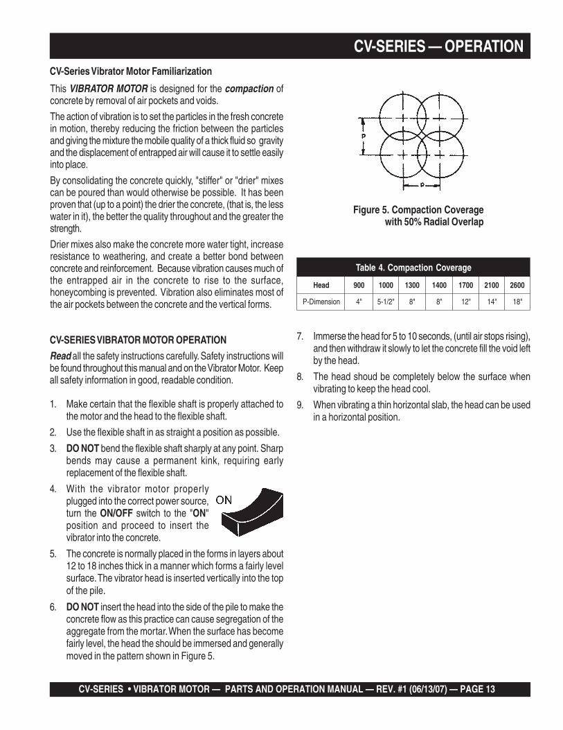
6. DO NOT insert the head into the side of the pile to make theconcrete flow as this practice can cause segregation of theaggregate from the mortar. When the surface has becomefairly level, the head the should be immersed and generallymoved in the pattern shown in Figure 5.
Figure 5. Compaction Coveragewith 50% Radial Overlap
7. Immerse the head for 5 to 10 seconds, (until air stops rising),and then withdraw it slowly to let the concrete fill the void leftby the head.
8. The head shoud be completely below the surface whenvibrating to keep the head cool.
9. When vibrating a thin horizontal slab, the head can be usedin a horizontal position.
egarevoCnoitcapmoC.4elbaT
daeH 009 0001 0031 0041 0071 0012 0062
noisnemiD-P "4 "2/1-5 "8 "8 "21 "41 "81
PAGE 14 — STR 31VCV-SERIES • VIBRATOR MOTOR — PARTS AND OPERATION MANUAL — REV. #1 (06/13/07) — PAGE 14
CAUTIONCAUTIONCAUTIONCAUTIONCAUTION
NOTE
CV-SERIES — MAINTENANCEMAINTENANCE
Before performing any maintenance on this unit, ALWAYSMAKE CERTAIN that the switch is in the "OFF" positionand the power cord is disconnected from the power source.
This is a universal motor and it will run at approximately its ratedspeed if the motor and its attached equipment are properlyoperated and maintained.
9. Vibrator heads should be inspected and relubricated every100 hours of operation. Follow the instructions for vibratorheads.
Heat should be used to break downthe threadlock (loctite) while youunthread the head from the shaft. Thiswill help prevent damage to thethreads.
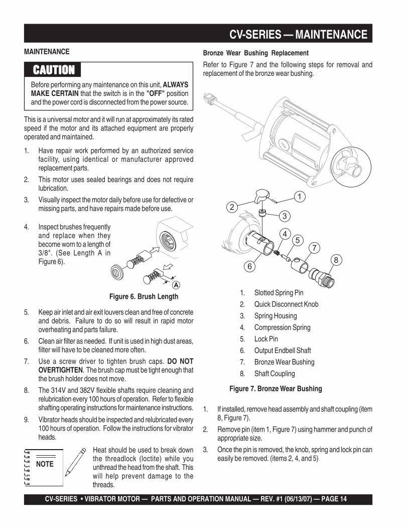
Bronze Wear Bushing Replacement
Refer to Figure 7 and the following steps for removal andreplacement of the bronze wear bushing.
1
2
5
6
7
8
4
3
1. Slotted Spring Pin
2. Quick Disconnect Knob
3. Spring Housing
4. Compression Spring
5. Lock Pin
6. Output Endbell Shaft
7. Bronze Wear Bushing
8. Shaft Coupling
Figure 7. Bronze Wear Bushing
1. If installed, remove head assembly and shaft coupling (item8, Figure 7).
2. Remove pin (item 1, Figure 7) using hammer and punch ofappropriate size.
3. Once the pin is removed, the knob, spring and lock pin caneasily be removed. (items 2, 4, and 5)
1. Have repair work performed by an authorized servicefacility, using identical or manufacturer approvedreplacement parts.
2. This motor uses sealed bearings and does not requirelubrication.
3. Visually inspect the motor daily before use for defective ormissing parts, and have repairs made before use.
A
4. Inspect brushes frequentlyand replace when theybecome worn to a length of3/8". (See Length A inFigure 6).
Figure 6. Brush Length
5. Keep air inlet and air exit louvers clean and free of concreteand debris. Failure to do so will result in rapid motoroverheating and parts failure.
6. Clean air filter as needed. If unit is used in high dust areas,filter will have to be cleaned more often.
7. Use a screw driver to tighten brush caps. DO NOTOVERTIGHTEN. The brush cap must be tight enough thatthe brush holder does not move.
8. The 314V and 382V flexible shafts require cleaning andrelubrication every 100 hours of operation. Refer to flexibleshafting operating instructions for maintenance instructions.

CV-SERIES • VIBRATOR MOTOR — PARTS AND OPERATION MANUAL — REV. #1 (06/13/07) — PAGE 15
4. Using channel lock style pliers with soft jaws, unscrew thespring housing (item 3). Heat may need to be applied tobreak down the old threadlock to prevent damage to thethreads on the spring housing.
5. After the spring housing is removed, use a 3-jaw bearingpuller to remove the bronze wear bushing, (item 7).
6. To install a new bronze wear bushing, first align the hole inthe new bushing with the spring housing hole. Press thebushing straight and evenly into place using a block ofwood or soft aluminum and a mallet. Bushing should beflush with the end of the shaft when fully seated.
7. Clean all old threadlock from the spring housing and applynew threadlock (Loctite blue 242 or equivalent).
8. Screw the spring housing firmly into place using channellock style pliers with soft jaws.
9. Reinstall the lock pin, spring and knob and secure with pin.
10. Verifiy the Quick Disconnect Knob operates freely andsnaps back into position. If the knob stays in the up positionthere is binding occurring between the knob, spring, orlock pin.
Motor Reassembly
Refer to Figure 8 or the Vibrator Motor Assembly illustration onpage 22 when performing the following steps.
1. Place the Brush Endbell (item 1, Figure 8) on work surfacewith bearing pocket up.
2. Place two plastic insulators (items 2) in the holes on theendbell.
3. Slide the Field Assembly (item 4), with the leads towardthe endbell, into place ensuring the plastic insulatorsengage into the field holes.
4. Plug the brush flag leads (see Figure 9, Field Orientation)into the top of the brush holders toward the output shaftend. (See Figure 10).
5. Install the Armature/bearings Assembly (item 5) and WaveSpring (item 3) through the Field and into the endbellbearing pocket.
6. Place the remaining two plastic insulators (items 6) into theholes of the Output Endbell (item 7).
If the motor required disassembly for servicing, reinstalling theassembly back into the case will be much easier if all internalcomponents are reassembled as a unit first.
1. Brush Endbell
2. Plastic Insulator
3. Wave Loading Spring
4. Field Assembly
5. Armature & Bearing Assembly
6. Plastic Insulator
7. Output Endbell
8. Lock Washer
9. Screw
Figure 8. Motor Assembly
1
2
2 3
4
5
6
6
7
8
9
CV-SERIES — MAINTENANCE
PAGE 16 — STR 31VCV-SERIES • VIBRATOR MOTOR — PARTS AND OPERATION MANUAL — REV. #1 (06/13/07) — PAGE 16
2
3 4 5
1
7. Slide the Output Endbell (item 7) down onto the Armature/Bearing Assembly (item 5) so the bearing engages thebearing pocket of the endbell and insulators seat properlyon the Field.
8. Install the lockwashers and long screws through bothendbells as shown and torque to 50-70 in. lbs. (5.65 N-m to7.91 N-m).
9. Place the motor assembly into the plastic housing half thathas the threaded inserts. (item 1 Figure 11)
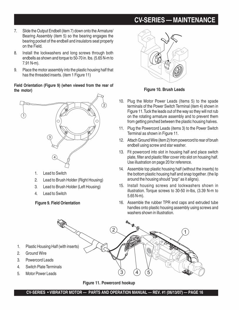
Field Orientation (Figure 9) (when viewed from the rear ofthe motor)
CV-SERIES — MAINTENANCE
1. Lead to Switch
2. Lead to Brush Holder (Right Housing)
3. Lead to Brush Holder (Left Housing)
4. Lead to Switch
Figure 9. Field Orientation
Figure 11. Powercord hookup
Figure 10. Brush Leads
4
1
2
3
1. Plastic Housing Half (with inserts)
2. Ground Wire
3. Powercord Leads
4. Switch Plate Terminals
5. Motor Power Leads
15. Install housing screws and lockwashers shown inillustration. Torque screws to 30-50 in-lbs, (3.39 N-m to5.65 N-m).
16. Assemble the rubber TPR end caps and extruded tubehandles onto plastic housing assembly using screws andwashers shown in illustration.
10. Plug the Motor Power Leads (Items 5) to the spadeterminals of the Power Switch Terminal (item 4) shown inFigure 11. Tuck the leads out of the way so they will not rubon the rotating armature assembly and to prevent themfrom getting pinched between the plastic housing halves.
11. Plug the Powercord Leads (items 3) to the Power SwitchTerminal as shown in Figure 11.
12. Attach Ground Wire (item 2) from powercord to rear of brushendbell using screw and star washer.
13. Fit powercord into slot in housing half and place switchplate, filter and plastic filter cover into slot on housing half.Use illustration on page 20 for reference.
14. Assemble top plastic housing half (without the inserts) tothe bottom plastic housing half and snap together. (the liparound the housing should "pop" as it aligns).
CV-SERIES • VIBRATOR MOTOR — PARTS AND OPERATION MANUAL — REV. #1 (06/13/07) — PAGE 17
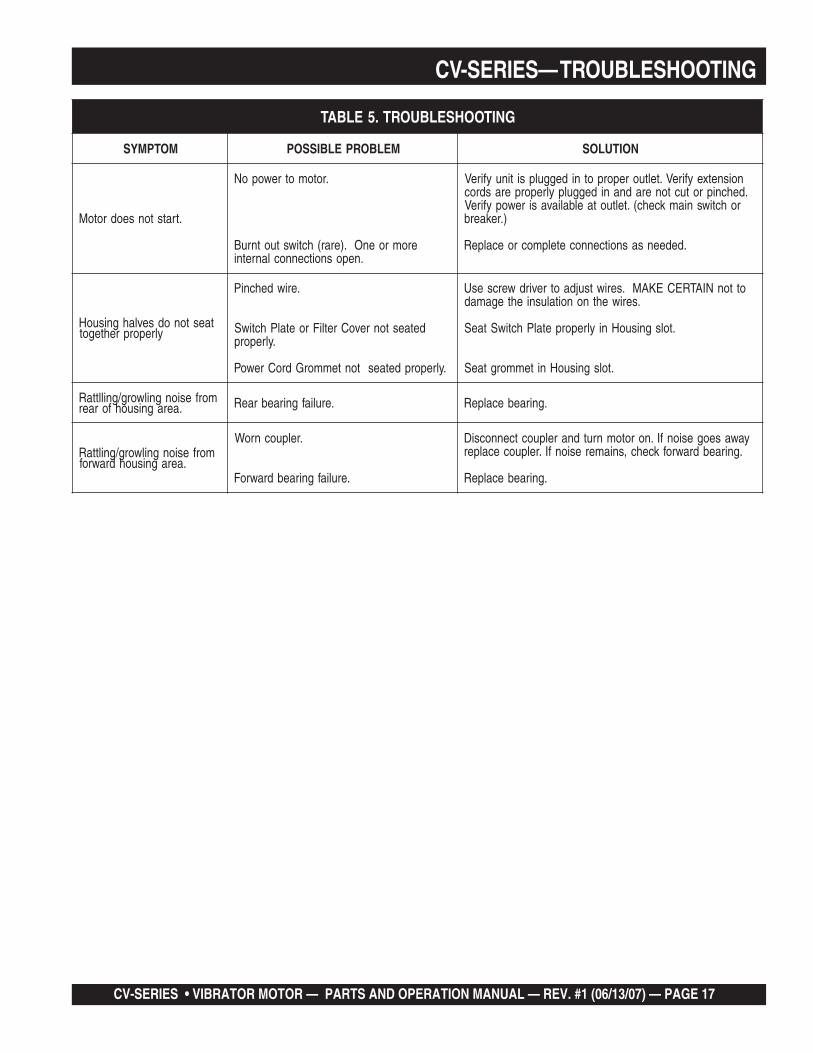
CV-SERIES— TROUBLESHOOTING
GNITOOHSELBUORT.5ELBAT
MOTPMYS MELBORPELBISSOP NOITULOS
.tratstonseodrotoM
.rotomotrewopoN
eromroenO.)erar(hctiwstuotnruB.neposnoitcennoclanretni
noisnetxeyfireV.teltuoreporpotnideggulpsitinuyfireV.dehcniprotuctoneradnanideggulpylreporperasdroc
rohctiwsniamkcehc(.teltuotaelbaliavasirewopyfireV).rekaerb
.dedeensasnoitcennocetelpmocroecalpeR
taestonodsevlahgnisuoHylreporprehtegot
.eriwdehcniP
detaestonrevoCretliFroetalPhctiwS.ylreporp
.ylreporpdetaestontemmorGdroCrewoP
ottonNIATRECEKAM.seriwtsujdaotrevirdwercsesU.seriwehtnonoitalusniehtegamad
.tolsgnisuoHniylreporpetalPhctiwStaeS
.tolsgnisuoHnitemmorgtaeS
morfesiongnilworg/gnillttaR.aeragnisuohforaer .eruliafgniraebraeR .gniraebecalpeR
morfesiongnilworg/gnilttaR.aeragnisuohdrawrof
.relpuocnroW
.eruliafgniraebdrawroF
yawaseogesionfI.norotomnrutdnarelpuoctcennocsiD.gniraebdrawrofkcehc,sniameresionfI.relpuocecalper
.gniraebecalpeR
PAGE 18 — STR 31VCV-SERIES • VIBRATOR MOTOR — PARTS AND OPERATION MANUAL — REV. #1 (06/13/07) — PAGE 18
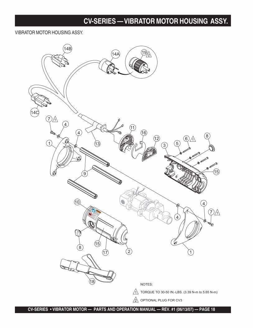
CV-SERIES — VIBRATOR MOTOR HOUSING ASSY.VIBRATOR MOTOR HOUSING ASSY.
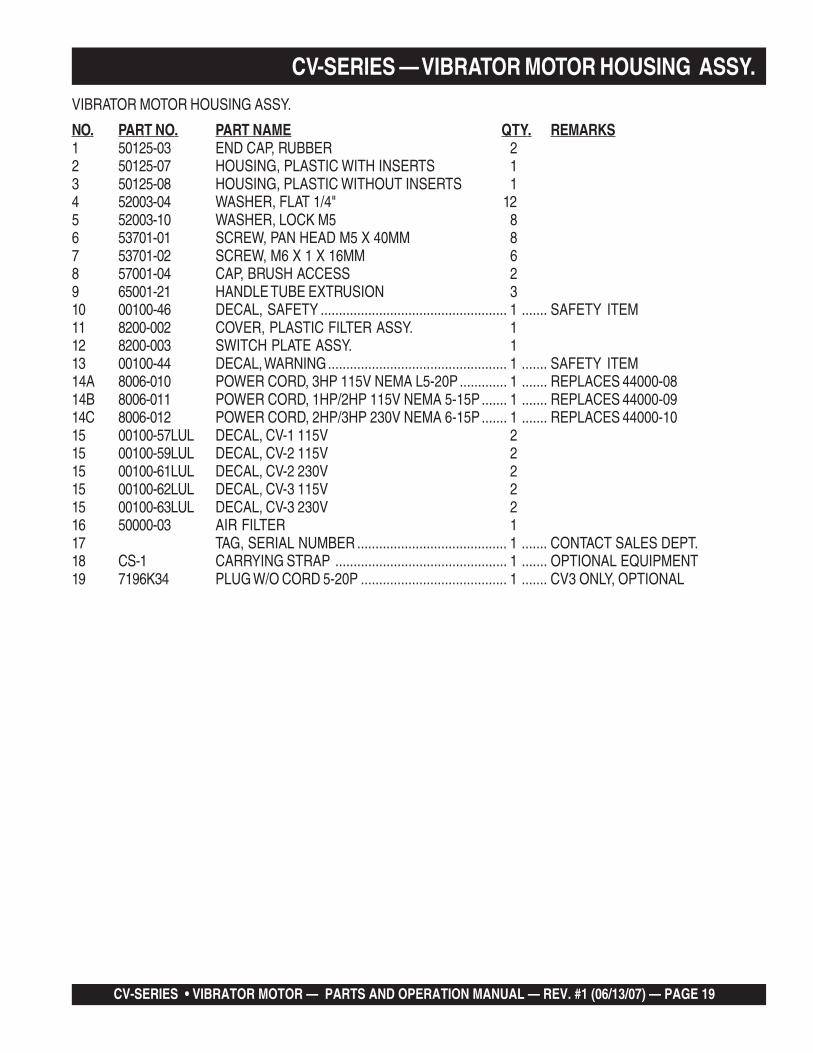
CV-SERIES • VIBRATOR MOTOR — PARTS AND OPERATION MANUAL — REV. #1 (06/13/07) — PAGE 19
CV-SERIES — VIBRATOR MOTOR HOUSING ASSY.VIBRATOR MOTOR HOUSING ASSY.
NO. PART NO. PART NAME QTY. REMARKS1 50125-03 END CAP, RUBBER 22 50125-07 HOUSING, PLASTIC WITH INSERTS 13 50125-08 HOUSING, PLASTIC WITHOUT INSERTS 14 52003-04 WASHER, FLAT 1/4" 125 52003-10 WASHER, LOCK M5 86 53701-01 SCREW, PAN HEAD M5 X 40MM 87 53701-02 SCREW, M6 X 1 X 16MM 68 57001-04 CAP, BRUSH ACCESS 29 65001-21 HANDLE TUBE EXTRUSION 310 00100-46 DECAL, SAFETY ................................................... 1 ....... SAFETY ITEM11 8200-002 COVER, PLASTIC FILTER ASSY. 112 8200-003 SWITCH PLATE ASSY. 113 00100-44 DECAL, WARNING................................................. 1 ....... SAFETY ITEM14A 8006-010 POWER CORD, 3HP 115V NEMA L5-20P ............. 1 ....... REPLACES 44000-0814B 8006-011 POWER CORD, 1HP/2HP 115V NEMA 5-15P ....... 1 ....... REPLACES 44000-0914C 8006-012 POWER CORD, 2HP/3HP 230V NEMA 6-15P ....... 1 ....... REPLACES 44000-1015 00100-57LUL DECAL, CV-1 115V 215 00100-59LUL DECAL, CV-2 115V 215 00100-61LUL DECAL, CV-2 230V 215 00100-62LUL DECAL, CV-3 115V 215 00100-63LUL DECAL, CV-3 230V 216 50000-03 AIR FILTER 117 TAG, SERIAL NUMBER ......................................... 1 ....... CONTACT SALES DEPT.18 CS-1 CARRYING STRAP ............................................... 1 ....... OPTIONAL EQUIPMENT19 7196K34 PLUG W/O CORD 5-20P ........................................ 1 ....... CV3 ONLY, OPTIONAL
PAGE 20 — STR 31VCV-SERIES • VIBRATOR MOTOR — PARTS AND OPERATION MANUAL — REV. #1 (06/13/07) — PAGE 20
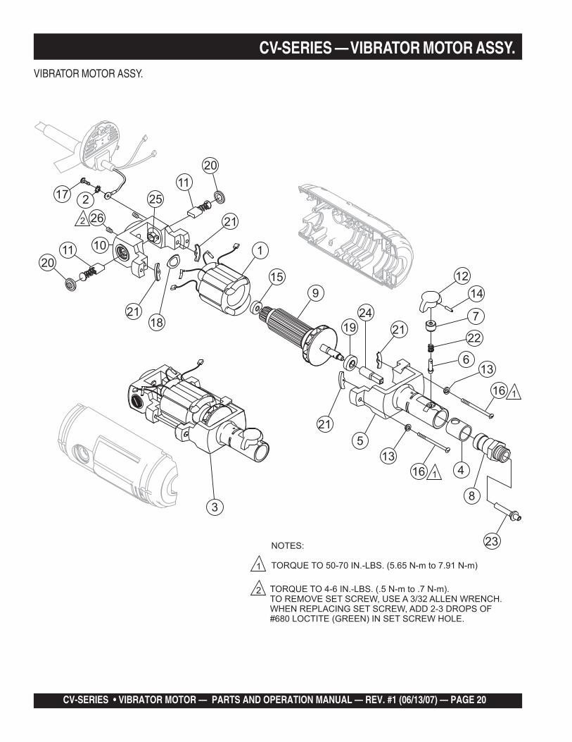
CV-SERIES — VIBRATOR MOTOR ASSY.VIBRATOR MOTOR ASSY.
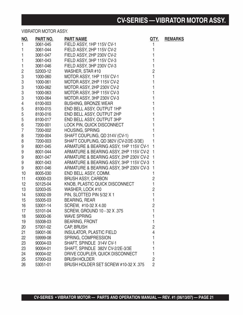
CV-SERIES • VIBRATOR MOTOR — PARTS AND OPERATION MANUAL — REV. #1 (06/13/07) — PAGE 21
CV-SERIES — VIBRATOR MOTOR ASSY.VIBRATOR MOTOR ASSY.
NO. PART NO. PART NAME QTY. REMARKS1 3061-045 FIELD ASSY, 1HP 115V CV-1 11 3061-044 FIELD ASSY, 2HP 115V CV-2 11 3061-047 FIELD ASSY, 2HP 230V CV-2 11 3061-043 FIELD ASSY, 3HP 115V CV-3 11 3061-046 FIELD ASSY, 3HP 230V CV-3 12 52003-12 WASHER, STAR #10 23 1000-060 MOTOR ASSY, 1HP 115V CV-1 13 1000-061 MOTOR ASSY, 2HP 115V CV-2 13 1000-062 MOTOR ASSY, 2HP 230V CV-2 13 1000-063 MOTOR ASSY, 3HP 115V CV-3 13 1000-064 MOTOR ASSY, 3HP 230V CV-3 14 6100-003 BUSHING, BRONZE WEAR 15 8100-015 END BELL ASSY, OUTPUT 1HP 15 8100-016 END BELL ASSY, OUTPUT 2HP 15 8100-017 END BELL ASSY, OUTPUT 3HP 16 7200-001 LOCK PIN, QUICK DISCONNECT 17 7200-002 HOUSING, SPRING 18 7200-004 SHAFT COUPLING, QD 314V (CV-1) 18 7200-003 SHAFT COUPLING, QD 382V (CV-2/2E-3/3E) 19 8001-045 ARMATURE & BEARING ASSY, 1HP 115V CV-1 19 8001-044 ARMATURE & BEARING ASSY, 2HP 115V CV-2 19 8001-047 ARMATURE & BEARING ASSY, 2HP 230V CV-2 19 8001-043 ARMATURE & BEARING ASSY, 3HP 115V CV-3 19 8001-046 ARMATURE & BEARING ASSY, 3HP 230V CV-3 110 8005-030 END BELL ASSY, COMM. 111 43000-03 BRUSH ASSY, CARBON 212 50125-04 KNOB, PLASTIC QUICK DISCONNECT 113 52003-05 WASHER, LOCK #10 214 53002-09 PIN, SLOTTED PIN 5/32 X 1 115 55005-03 BEARING, REAR 116 53001-14 SCREW, #10-32 X 4.00 217 53101-04 SCREW, GROUND 10 - 32 X .375 118 56000-06 WAVE SPRING 119 55008-03 BEARING, FRONT 120 57001-02 CAP, BRUSH 221 59001-06 INSULATOR, PLASTIC FIELD 422 59999-08 SPRING, COMPRESSION 123 90004-03 SHAFT, SPINDLE 314V CV-1 123 90004-01 SHAFT, SPINDLE 382V CV-2/2E-3/3E 124 90004-02 DRIVE COUPLER, QUICK DISCONNECT 125 57000-03 BRUSH HOLDER 226 53051-01 BRUSH HOLDER SET SCREW #10-32 X .375 2
PAGE 22 — STR 31VCV-SERIES • VIBRATOR MOTOR — PARTS AND OPERATION MANUAL — REV. #1 (06/13/07) — PAGE 22
Effective: February 22, 2006 TERMS AND CONDITIONS OF SALE — PARTS
PAYMENT TERMS
Terms of payment for parts are net 30 days.
FREIGHT POLICY
All parts orders will be shipped collect orprepaid with the charges added to the invoice.All shipments are F.O.B. point of origin.Multiquip’s responsibility ceases when a signedmanifest has been obtained from the carrier,and any claim for shortage or damage must besettled between the consignee and the carrier.
MINIMUM ORDER
The minimum charge for orders from Multiquipis $15.00 net. Customers will be asked forinstructions regarding handling of orders notmeeting this requirement.
RETURNED GOODS POLICY
Return shipments will be accepted and creditwill be allowed, subject to the following provi-sions:
1. A Returned Material Authorization mustbe approved by Multiquip prior to ship-ment.
2. To obtain a Return Material Authorization,a list must be provided to Multiquip PartsSales that defines item numbers, quanti-ties, and descriptions of the items to bereturned.
a. The parts numbers and descriptionsmust match the current parts pricelist.
b. The list must be typed or computergenerated.
c. The list must state the reason(s) forthe return.
d. The list must reference the salesorder(s) or invoice(s) under which theitems were originally purchased.
e. The list must include the name andphone number of the person request-ing the RMA.
3. A copy of the Return Material Authoriza-tion must accompany the return shipment.
4. Freight is at the sender’s expense. Allparts must be returned freight prepaid toMultiquip’s designated receiving point.
5. Parts must be in new and resalable con-dition, in the original Multiquip package (ifany), and with Multiquip part numbersclearly marked.
6. The following items are not returnable:
a. Obsolete parts. (If an item is in theprice book and shows as being re-placed by another item, it is obsolete.)
b. Any parts with a limited shelf life(such as gaskets, seals, “O” rings,and other rubber parts) that were pur-chased more than six months prior tothe return date.
c. Any line item with an extended dealernet price of less than $5.00.
d. Special order items.
e. Electrical components.
f. Paint, chemicals, and lubricants.
g. Decals and paper products.
h. Items purchased in kits.
7. The sender will be notified of any materialreceived that is not acceptable.
8. Such material will be held for five workingdays from notification, pending instruc-tions. If a reply is not received within fivedays, the material will be returned to thesender at his expense.
9. Credit on returned parts will be issued atdealer net price at time of the originalpurchase, less a 15% restocking charge.
10. In cases where an item is accepted, forwhich the original purchase documentcan not be determined, the price will bebased on the list price that was effectivetwelve months prior to the RMA date.
11. Credit issued will be applied to futurepurchases only.
PRICING AND REBATES
Prices are subject to change without priornotice. Price changes are effective on a spe-cific date and all orders received on or after thatdate will be billed at the revised price. Rebatesfor price declines and added charges for priceincreases will not be made for stock on handat the time of any price change.
Multiquip reserves the right to quote and selldirect to Government agencies, and to OriginalEquipment Manufacturer accounts who useour products as integral parts of their ownproducts.
SPECIAL EXPEDITING SERVICE
A $35.00 surcharge will be added to the invoicefor special handling including bus shipments,insured parcel post or in cases where Multiquipmust personally deliver the parts to the carrier.
LIMITATIONS OF SELLER’S LIABILITY
Multiquip shall not be liable hereunder fordamages in excess of the purchase price of theitem with respect to which damages areclaimed, and in no event shall Multiquip beliable for loss of profit or good will or for anyother special, consequential or incidental dam-ages.
LIMITATION OF WARRANTIES
No warranties, express or implied, are madein connection with the sale of parts or tradeaccessories nor as to any engine not manufac-tured by Multiquip. Such warranties made inconnection with the sale of new, complete unitsare made exclusively by a statement of war-ranty packaged with such units, and Multiquipneither assumes nor authorizes any person toassume for it any other obligation or liabilitywhatever in connection with the sale of itsproducts. Apart from such written statement ofwarranty, there are no warranties, express,implied or statutory, which extend beyond thedescription of the products on the face hereof.
CV-SERIES • VIBRATOR MOTOR — PARTS AND OPERATION MANUAL — REV. #1 (06/13/07) — PAGE 23
CV-SERIES — NOTES
OPERATION AND PARTS MANUAL
Your Local Dealer is:
HERE'S HOW TO GET HELPPLEASE HAVE THE MODEL AND SERIAL
NUMBER ON-HAND WHEN CALLING
© COPYRIGHT 2007, MULTIQUIP INC.
Multiquip Inc and the MQ logo are registered trademarks of Multiquip Inc. and may not be used, reproduced, or altered without written permission. All other trademarks arethe property of their respective owners and used with permission.
This manual MUST accompany the equipment at all times. This manual is considered a permanent part of the equipment and should remain with the unit if resold.
The information and specifications included in this publication were in effect at the time of approval for printing. Illustrations are based on the CV Series Vibrator Motor.Illustrations, descriptions, references and technical data contained in this manual are for guidance only and may not be considered as binding. Multiquip Inc. reserves theright to discontinue or change specifications, design or the information published in this publication at any time without notice and without incurring any obligations.
UNITED STATESMultiquip Corporate Office MQ Parts Department18910 Wilmington Ave. Tel. (800) 421-1244 800-427-1244 Fax: 800-672-7877Carson, CA 90746 Fax (800) 537-3927 310-537-3700 Fax: 310-637-3284Contact: [email protected] Parts Warranty Department800-306-2926 Fax: 800-672-7877 800-421-1244, Ext. 279 Fax: 310-537-1173310-537-3700 Fax: 310-637-3284 310-537-3700, Ext. 279Service Department Technial Assistance800-421-1244 Fax: 310-537-4259 800-478-1244 Fax: 310-631-5032310-537-3700
MEXICO UNITED KINGDOMMQ Cipsa Multiquip (UK) Limited Head OfficeCarr. Fed. Mexico-Puebla KM 126.5 Tel: (52) 222-225-9900 Hanover Mill, Fitzroy Street, Tel: 0161 339 2223Momoxpan, Cholula, Puebla 72760 Mexico Fax: (52) 222-285-0420 Ashton-under-Lyne, Fax: 0161 339 3226Contact: [email protected] Lancashire OL7 0TL
Contact: [email protected]
CANADA BRAZILMultiquip Multiquip4110 Industriel Boul. Tel: (450) 625-2244 Av. Evandro Lins e Silva, 840 - grupo 505 Tel: 011-55-21-3433-9055Laval, Quebec, Canada H7L 6V3 Fax: (450) 625-8664 Barra de Tijuca - Rio de Janeiro Fax: 011-55-21-3433-9055Contact: [email protected] Contact: [email protected], [email protected]