Embed Size (px)
Citation preview
670Revised 3/99
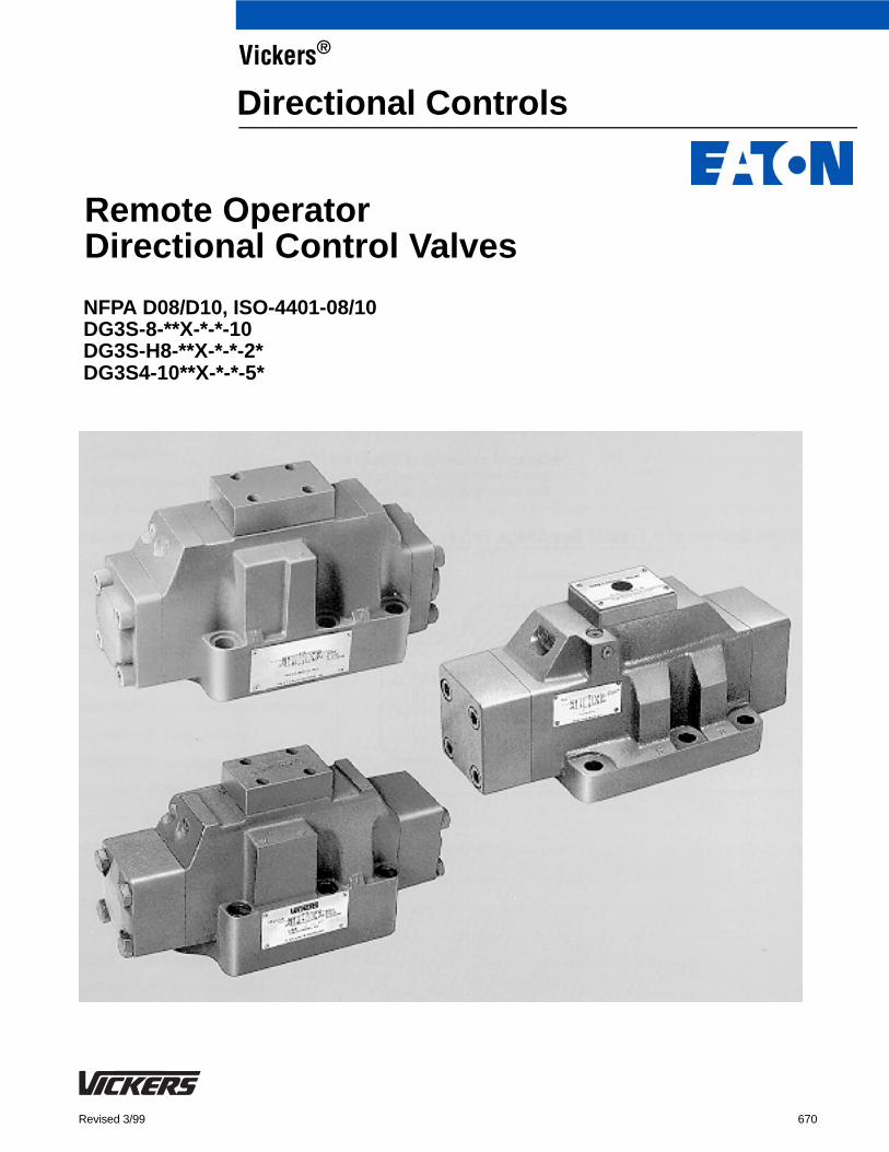
NFPA D08/D10, ISO-4401-08/10DG3S-8-**X-*-*-10DG3S-H8-**X-*-*-2*DG3S4-10**X-*-*-5*
Remote OperatorDirectional Control Valves
Vickers®
Directional Controls
2
Introduction
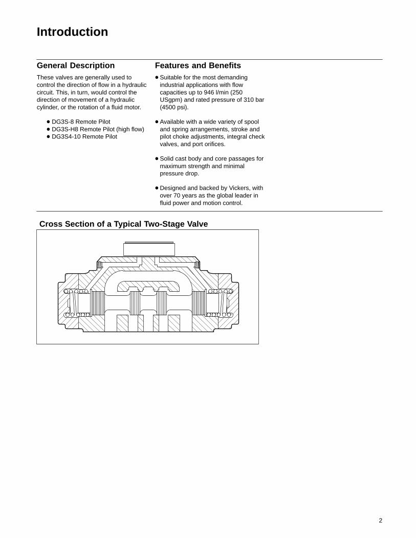
General DescriptionThese valves are generally used tocontrol the direction of flow in a hydrauliccircuit. This, in turn, would control thedirection of movement of a hydrauliccylinder, or the rotation of a fluid motor.
� DG3S-8 Remote Pilot� DG3S-H8 Remote Pilot (high flow)� DG3S4-10 Remote Pilot
Features and Benefits� Suitable for the most demanding
industrial applications with flowcapacities up to 946 l/min (250USgpm) and rated pressure of 310 bar(4500 psi).
� Available with a wide variety of spooland spring arrangements, stroke andpilot choke adjustments, integral checkvalves, and port orifices.
� Solid cast body and core passages formaximum strength and minimalpressure drop.
� Designed and backed by Vickers, withover 70 years as the global leader influid power and motion control.
Cross Section of a Typical Two-Stage Valve
3
Contents
DG3S-8 Model Code 4. . . . . . . . . . . . . . . . . . . . . . . . . . . . . . . . . . . . . . . . . . . . . . . . . . . . . . . . . . . . . . . . . . . . . . . . . . . . . . . . .
DG3S-8 Pilot Pressure 4. . . . . . . . . . . . . . . . . . . . . . . . . . . . . . . . . . . . . . . . . . . . . . . . . . . . . . . . . . . . . . . . . . . . . . . . . . . . . . . .
General Information 5. . . . . . . . . . . . . . . . . . . . . . . . . . . . . . . . . . . . . . . . . . . . . . . . . . . . . . . . . . . . . . . . . . . . . . . . . . . . . . . . . .
DG3S-8 Basic Characteristics 5. . . . . . . . . . . . . . . . . . . . . . . . . . . . . . . . . . . . . . . . . . . . . . . . . . . . . . . . . . . . . . . . . . . . . . . .
DG3S-H8 Basic Characteristics 5. . . . . . . . . . . . . . . . . . . . . . . . . . . . . . . . . . . . . . . . . . . . . . . . . . . . . . . . . . . . . . . . . . . . . .
DG3S4-10 Basic Characteristics 5. . . . . . . . . . . . . . . . . . . . . . . . . . . . . . . . . . . . . . . . . . . . . . . . . . . . . . . . . . . . . . . . . . . . . .
Optional Features 5. . . . . . . . . . . . . . . . . . . . . . . . . . . . . . . . . . . . . . . . . . . . . . . . . . . . . . . . . . . . . . . . . . . . . . . . . . . . . . . . .
Mounting Position 5. . . . . . . . . . . . . . . . . . . . . . . . . . . . . . . . . . . . . . . . . . . . . . . . . . . . . . . . . . . . . . . . . . . . . . . . . . . . . . . . .
Installation Data 6. . . . . . . . . . . . . . . . . . . . . . . . . . . . . . . . . . . . . . . . . . . . . . . . . . . . . . . . . . . . . . . . . . . . . . . . . . . . . . . . . .
Shifting Action 6. . . . . . . . . . . . . . . . . . . . . . . . . . . . . . . . . . . . . . . . . . . . . . . . . . . . . . . . . . . . . . . . . . . . . . . . . . . . . . . . . . . .
Service Literature 6. . . . . . . . . . . . . . . . . . . . . . . . . . . . . . . . . . . . . . . . . . . . . . . . . . . . . . . . . . . . . . . . . . . . . . . . . . . . . . . . .
DG3S-8-**-10 Max. Flow rating & Symbols 7. . . . . . . . . . . . . . . . . . . . . . . . . . . . . . . . . . . . . . . . . . . . . . . . . . . . . . . . . . . . . . . . .
DG3S-8-**-10 Pressure Drop 9. . . . . . . . . . . . . . . . . . . . . . . . . . . . . . . . . . . . . . . . . . . . . . . . . . . . . . . . . . . . . . . . . . . . . . . . . . .
DG3S-8-**-10 Pressure Drop Across Check Valve 10. . . . . . . . . . . . . . . . . . . . . . . . . . . . . . . . . . . . . . . . . . . . . . . . . . . . . . . . . .
DG3S-8-**-10 Installation Dimensions 11. . . . . . . . . . . . . . . . . . . . . . . . . . . . . . . . . . . . . . . . . . . . . . . . . . . . . . . . . . . . . . . . . . . .
DG3S-8-**-10 Adjustment Options 12. . . . . . . . . . . . . . . . . . . . . . . . . . . . . . . . . . . . . . . . . . . . . . . . . . . . . . . . . . . . . . . . . . . . . .
DG3S-H8 Model Code 13. . . . . . . . . . . . . . . . . . . . . . . . . . . . . . . . . . . . . . . . . . . . . . . . . . . . . . . . . . . . . . . . . . . . . . . . . . . . . . .
DG3S-H8 Pilot Pressure 13. . . . . . . . . . . . . . . . . . . . . . . . . . . . . . . . . . . . . . . . . . . . . . . . . . . . . . . . . . . . . . . . . . . . . . . . . . . . . .
DG3S-H8-**-2* Max. Flow Ratings & Symbols 14. . . . . . . . . . . . . . . . . . . . . . . . . . . . . . . . . . . . . . . . . . . . . . . . . . . . . . . . . . . . .
DG3S-H8-**-2* Pressure Drop 16. . . . . . . . . . . . . . . . . . . . . . . . . . . . . . . . . . . . . . . . . . . . . . . . . . . . . . . . . . . . . . . . . . . . . . . . .
DG3S-H8-**-2* Installation Dimensions 17. . . . . . . . . . . . . . . . . . . . . . . . . . . . . . . . . . . . . . . . . . . . . . . . . . . . . . . . . . . . . . . . . .
DG3S-H8-**-2* Adjustment Options 18. . . . . . . . . . . . . . . . . . . . . . . . . . . . . . . . . . . . . . . . . . . . . . . . . . . . . . . . . . . . . . . . . . . . .
DG3S-H8-**-2* Pressure Drop Across Check Valve 19. . . . . . . . . . . . . . . . . . . . . . . . . . . . . . . . . . . . . . . . . . . . . . . . . . . . . . . . .
DG3S-(H)8-**-10/2* Subplates & Bolt Kits 20. . . . . . . . . . . . . . . . . . . . . . . . . . . . . . . . . . . . . . . . . . . . . . . . . . . . . . . . . . . . . . . .
DG3S4-10 Model Code 21. . . . . . . . . . . . . . . . . . . . . . . . . . . . . . . . . . . . . . . . . . . . . . . . . . . . . . . . . . . . . . . . . . . . . . . . . . . . . .
DG3S4-10 Min. Pilot Pressure 21. . . . . . . . . . . . . . . . . . . . . . . . . . . . . . . . . . . . . . . . . . . . . . . . . . . . . . . . . . . . . . . . . . . . . . . . .
DG3S4-10**-5* Ratings 22. . . . . . . . . . . . . . . . . . . . . . . . . . . . . . . . . . . . . . . . . . . . . . . . . . . . . . . . . . . . . . . . . . . . . . . . . . . . . .
DG3S4-10**-5* Installation Dimensions 24. . . . . . . . . . . . . . . . . . . . . . . . . . . . . . . . . . . . . . . . . . . . . . . . . . . . . . . . . . . . . . . . . .
DG3S4-10**-5* Adjustment Options 25. . . . . . . . . . . . . . . . . . . . . . . . . . . . . . . . . . . . . . . . . . . . . . . . . . . . . . . . . . . . . . . . . . . . .
DG3S4-10**-5* Subplates & Bolt Kits 26. . . . . . . . . . . . . . . . . . . . . . . . . . . . . . . . . . . . . . . . . . . . . . . . . . . . . . . . . . . . . . . . . . . .
Application Data 27. . . . . . . . . . . . . . . . . . . . . . . . . . . . . . . . . . . . . . . . . . . . . . . . . . . . . . . . . . . . . . . . . . . . . . . . . . . . . . . . . . . .
4
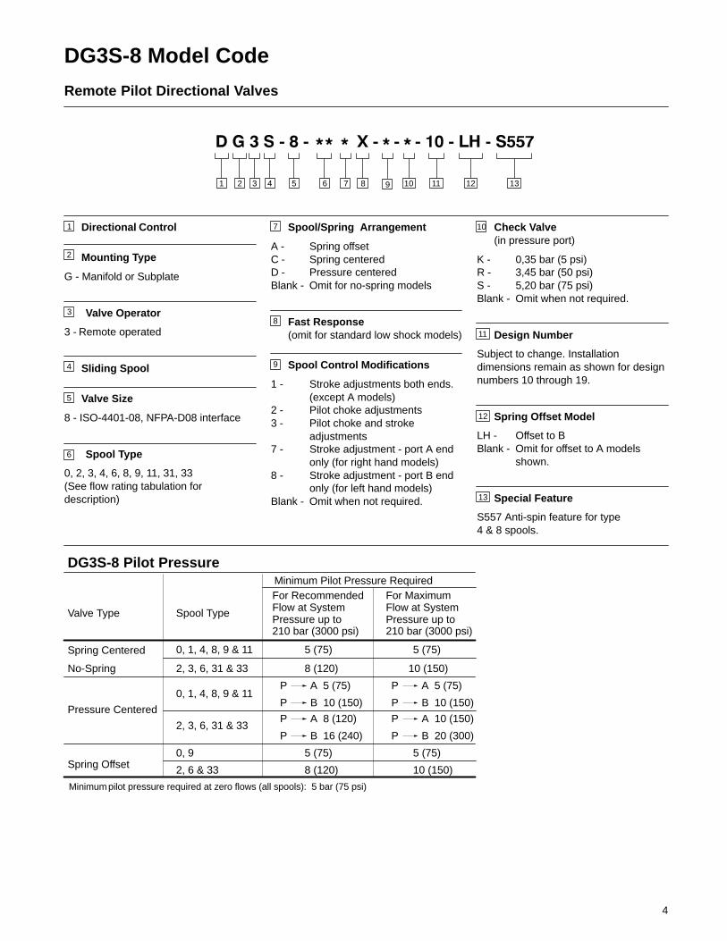
DG3S-8 Model Code
Remote Pilot Directional Valves
2 3 4 765 81 12
1
2
Directional Control
Mounting Type
G - Manifold or Subplate
Valve Operator
3 - Remote operated
Sliding Spool
Valve Size
8 - ISO-4401-08, NFPA-D08 interface
Spool Type
0, 2, 3, 4, 6, 8, 9, 11, 31, 33(See flow rating tabulation fordescription)
3
4
7
9
8
12
10
11
Spool/Spring Arrangement
A - Spring offsetC - Spring centeredD - Pressure centeredBlank - Omit for no-spring models
Fast Response(omit for standard low shock models)
Spool Control Modifications
1 - Stroke adjustments both ends.(except A models)
2 - Pilot choke adjustments3 - Pilot choke and stroke
adjustments7 - Stroke adjustment - port A end
only (for right hand models)8 - Stroke adjustment - port B end
only (for left hand models)Blank - Omit when not required.
Check Valve(in pressure port)
K - 0,35 bar (5 psi)R - 3,45 bar (50 psi)S - 5,20 bar (75 psi)Blank - Omit when not required.
Design Number
Subject to change. Installationdimensions remain as shown for designnumbers 10 through 19.
Spring Offset Model
LH - Offset to BBlank - Omit for offset to A models
shown.
Special Feature
S557 Anti-spin feature for type 4 & 8 spools.
10 11
5
6
9
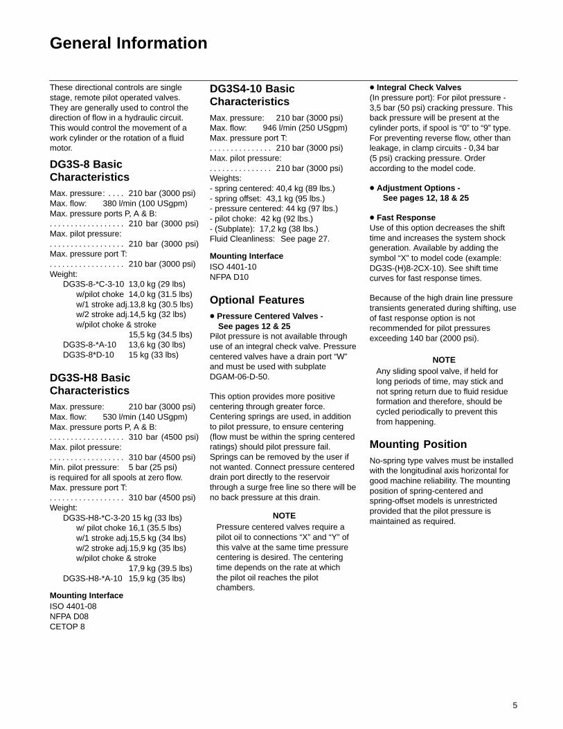
DG3S-8 Pilot Pressure
Valve Type Spool Type
Minimum Pilot Pressure RequiredFor Recommended Flow at SystemPressure up to 210 bar (3000 psi)
For Maximum Flow at SystemPressure up to 210 bar (3000 psi)
Spring Centered
No-Spring
Pressure Centered
Spring Offset
0, 1, 4, 8, 9 & 11
2, 3, 6, 31 & 33
0, 1, 4, 8, 9 & 11
2, 3, 6, 31 & 33
0, 9
2, 6 & 33
5 (75)
8 (120)
P A 5 (75)
P B 10 (150)
P A 5 (75)
P B 10 (150)
P A 8 (120)
P B 16 (240)
P A 10 (150)
P B 20 (300)
5 (75)
10 (150)
5 (75)
8 (120)
5 (75)
10 (150)
Minimum pilot pressure required at zero flows (all spools): 5 bar (75 psi)
13
13
5
General Information
These directional controls are singlestage, remote pilot operated valves.They are generally used to control thedirection of flow in a hydraulic circuit.This would control the movement of awork cylinder or the rotation of a fluidmotor.
DG3S-8 BasicCharacteristicsMax. pressure: 210 bar (3000 psi). . . . Max. flow: 380 l/min (100 USgpm)Max. pressure ports P, A & B:
210 bar (3000 psi). . . . . . . . . . . . . . . . . . Max. pilot pressure:
210 bar (3000 psi). . . . . . . . . . . . . . . . . . Max. pressure port T:
210 bar (3000 psi). . . . . . . . . . . . . . . . . . Weight:
DG3S-8-*C-3-10 13,0 kg (29 lbs)w/pilot choke 14,0 kg (31.5 lbs)w/1 stroke adj.13,8 kg (30.5 lbs)w/2 stroke adj.14,5 kg (32 lbs)w/pilot choke & stroke
15,5 kg (34.5 lbs)DG3S-8-*A-10 13,6 kg (30 lbs)DG3S-8*D-10 15 kg (33 lbs)
DG3S-H8 BasicCharacteristicsMax. pressure: 210 bar (3000 psi)Max. flow: 530 l/min (140 USgpm)Max. pressure ports P, A & B:
310 bar (4500 psi). . . . . . . . . . . . . . . . . . Max. pilot pressure:
310 bar (4500 psi). . . . . . . . . . . . . . . . . . Min. pilot pressure: 5 bar (25 psi)is required for all spools at zero flow.Max. pressure port T:
310 bar (4500 psi). . . . . . . . . . . . . . . . . . Weight:
DG3S-H8-*C-3-20 15 kg (33 lbs)w/ pilot choke 16,1 (35.5 lbs)w/1 stroke adj.15,5 kg (34 lbs)w/2 stroke adj.15,9 kg (35 lbs)w/pilot choke & stroke
17,9 kg (39.5 lbs)DG3S-H8-*A-10 15,9 kg (35 lbs)
Mounting InterfaceISO 4401-08NFPA D08CETOP 8
DG3S4-10 BasicCharacteristicsMax. pressure: 210 bar (3000 psi)Max. flow: 946 l/min (250 USgpm)Max. pressure port T:
210 bar (3000 psi). . . . . . . . . . . . . . . Max. pilot pressure:
210 bar (3000 psi). . . . . . . . . . . . . . . Weights: - spring centered: 40,4 kg (89 lbs.) - spring offset: 43,1 kg (95 lbs.)- pressure centered: 44 kg (97 lbs.)- pilot choke: 42 kg (92 lbs.)- (Subplate): 17,2 kg (38 lbs.)Fluid Cleanliness: See page 27.
Mounting InterfaceISO 4401-10 NFPA D10
Optional Features� Pressure Centered Valves -
See pages 12 & 25Pilot pressure is not available throughuse of an integral check valve. Pressurecentered valves have a drain port “W”and must be used with subplateDGAM-06-D-50.
This option provides more positivecentering through greater force.Centering springs are used, in additionto pilot pressure, to ensure centering(flow must be within the spring centeredratings) should pilot pressure fail.Springs can be removed by the user ifnot wanted. Connect pressure centereddrain port directly to the reservoirthrough a surge free line so there will beno back pressure at this drain.
NOTEPressure centered valves require apilot oil to connections “X” and “Y” ofthis valve at the same time pressurecentering is desired. The centeringtime depends on the rate at whichthe pilot oil reaches the pilotchambers.
� Integral Check Valves (In pressure port): For pilot pressure -3,5 bar (50 psi) cracking pressure. Thisback pressure will be present at thecylinder ports, if spool is “0” to “9” type.For preventing reverse flow, other thanleakage, in clamp circuits - 0,34 bar (5 psi) cracking pressure. Orderaccording to the model code.
� Adjustment Options - See pages 12, 18 & 25
� Fast ResponseUse of this option decreases the shifttime and increases the system shockgeneration. Available by adding thesymbol “X” to model code (example:DG3S-(H)8-2CX-10). See shift timecurves for fast response times.
Because of the high drain line pressuretransients generated during shifting, useof fast response option is notrecommended for pilot pressuresexceeding 140 bar (2000 psi).
NOTEAny sliding spool valve, if held forlong periods of time, may stick andnot spring return due to fluid residueformation and therefore, should becycled periodically to prevent thisfrom happening.
Mounting PositionNo-spring type valves must be installedwith the longitudinal axis horizontal forgood machine reliability. The mountingposition of spring-centered andspring-offset models is unrestrictedprovided that the pilot pressure ismaintained as required.

6
Installation DataDrain connection must be piped directlyto tank through a surge free line so therewill be no back pressure at this port.
Shifting ActionSpring centered, pressure centered andspring offset models require continuouspilot pressure to maintain shiftedposition. Spring centered models returnvalve spool to center position bycentering springs when pilot pressurefails or falls below minimum requirement.
Spring offset model has an internalspring which returns the spool to offsetposition when the pilot connection “X” isopen to tank. Pilot connection “Y”becomes a drain connection and mustbe piped directly to tank at atmosphericpressure through a surge-free tank line.Back pressure at this connection wouldcause valve to malfunction.
When pilot pressure is removed onno-spring models, the spool remains inthe last position attained provided thereis no unusual shock, vibration, pressuretransients and the spool axis ishorizontal.
Port connections are made by mountingthe valves on a subplate or manifoldhaving mounting dimensions whichconform to NFPA-D08/D10(ISO-4401-08/10) pattern.
CautionSurges of oil in a common pilot valvedrain line serving these and othervalves can be of sufficient magnitudeto cause inadvertent shifting of thesevalves. This is particularly critical inthe no-spring type valves. Separatedrain lines or a vented drain manifoldwith a continuous downward path totank is necessary. This applies toconnection “Y” on spring offsetvalves where “Y” is piped as a drainfor pressure centered models. Drainconnection “W” must be pipeddirectly to tank through a surge freeline so there will be no backpressure at this drain.
Service LiteratureRefer to specific Vickers parts drawingfor service parts information. A completeparts breakdown is contained in thesedrawings. Order by literature number.DG3S-8-*D*-10 I-3436-SDG3S-8-*A*-10 I-3437-SDG3S-8-*C*-10 I-3438-SDG3S-H8-*A*-20 I-3443-SDG3S-H8-*C*-20 I-3444-SDG3S4-10*A(X)-5* I-3563-SDG3S4-10*C(X)-5* I-3626-SDG3S4-10*D*-5* I-3569-S
A B
P T
Pressure Centered D
A B
P T
X Y
drain W
X Y
No-Spring
A B
P T
X
Spring Offset A
drain Y
� �
A B
P T
Spring Centered C
X Y
A B
P T
X Y
No-Spring Detented (DG3S-H8 only)

7
A B
P T
A B
P T
A B
P T
Spring Centered �
-C-
Spring Offset �
-A-
No-Spring Detented �
All Spools 0, 2, 6, 9 & 33 All Spools
Standard Spool Types
Center Position & Spool Type
Description Center Position
RecommendedFlow Capacity
at 207 bar(3000 psi)
l/min (USgpm)
DG3S-8-0C-10
A B
P T
“0”DG3S-8-0A-10 DG3S-8-0D-10 Opens to Tall ports
170
(45)
DG3S-8-1C-10
A B
P T
“2”
DG3S-8-0-10
Open P & A to TClosed B
170
(45)
DG3S-8-2C-10
A B
P T
“3”
DG3S-8-2-10
Closed P & Aopen B to T
170
(45)
DG3S-8-3C-10
A B
P T
“4”
Closed P & BOpen A to T
170
(45)
DG3S-8-4C-10
A B
P T
“6”
Tandem P to TClosedCrossover
95 (25) - A170 (45) - C & D
DG3S-8-6C-10
A B
P T
“8”
DG3S-8-6-10 Closed P onlyOpen A & B to T
DG3S-8-8C-10�
A B
P T
“33”
Tandem P to TOpen Crossover
170
(45)
Full flowRestricted flow
� See Direction of Flow Chart, next page.
X Y X A B
P T
X
drain Y
Y
PressureCentered �
-D-
X Y
drain W
0, 2, 6, 9 & 33
DG3S-8-9C-10
DG3S-8-11C-10
DG3S-8-31C-10
DG3S-8-33C-10
DG3S-8-2A-10
DG3S-8-6A-10
DG3S-8-9A-10
DG3S-8-33A-10
DG3S-8-9-10
DG3S-8-33-10
DG3S-8-1D-10
DG3S-8-2D-10
DG3S-8-3D-10
DG3S-8-4D-10
DG3S-8-6D-10
DG3S-8-8D-10
DG3S-8-9D-10
DG3S-8-11D-10
DG3S-8-31D-10
DG3S-8-33D-10
A B
P T
“1”
A B
P T
“9”
A B
“11”
P TA B
P T
“31”
Closed to Tall ports
Open to T all ports Over Tapers
Open P & B to TClosed A
Closed POpen A & B to TOver Tapers
170
(45)
133 (35) - A & C170 (45) - D
170
(45)
170
(45)
95 (25) - A170 (45) - C & D
� Fast valve switching of large oil volumes, without adequate decompression circuitry, can developinstantaneous flows well above the maximum ratings. The type eight (8) spool may spin within the body,causing unusual valve body wear when applied in this type of circuit. With this and other spool types, valvemalfunction might occur. Where these applications exist use the DG3S-8-10-S557 special designator forthe 4C and 8C anti-spin spools/spring.
DG3S-8-**-10 Max. FlowRatings & Graphical Symbols
– –
– –
– –
– –
– –
– –
8
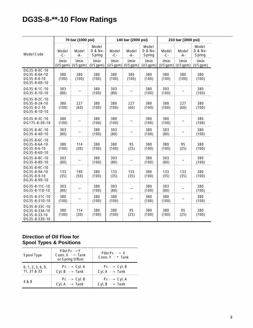
DG3S-8-**-10 Flow Ratings
DG3S-8-0C-10DG3S-8-0A-10DG3S-8-0-10DG3S-8-0D-10
Model Code
70 bar (1000 psi) 140 bar (2000 psi) 210 bar (3000 psi)
Model-C-
Model-A-
Model D & No-Spring
l/min(USgpm)
l/min(USgpm)
l/min(USgpm)
Model-C-
Model-A-
l/min(USgpm)
l/min(USgpm)
l/min(USgpm)
Model-C-
Model-A-
l/min(USgpm)
l/min(USgpm)
l/min(USgpm)
380(100)
380(100)
380(100)
380(100)
380(100)
380(100)
380(100)
380(100)
380(100)
DG3S-8-1C-10DG3S-8-1D-10
303(80)
380(100)
303(80)
380(100)
303(100)
380(100)
DG3S-8-2C-10DG3S-8-2A-10DG3S-8-2-10DG3S-8-1D-10
380(100)
380(100)
380(100)
380(100)
380(100)
227(60)
380(100)
DG3S-8-3C-10DG17S-8-3D-10
380(100)
– 380(100)
380(100)
380(100)
380(100)
380(100)
– –
DG3S-8-4C-10DG3S-8-4D-10
303(80)
380(100)
303(80)
380(100)
303(80)
380(100)
DG3S-8-6C-10DG3S-8-6A-10DG3S-8-6-10DG3S-8-6D-10
380(100)
380(100)
380(100)
DG3S-8-11C-10DG3S-8-11D-10
303(80)
380(100)
303(80)
380(100)
303(80)
380(100)
Direction of Oil Flow forSpool Types & Positions
Spool TypePilot Pr. Y
Conn. X Tankor Spring Offset
Pilot Pr. XConn. Y Tank
Cyl. A0, 1, 2, 3, 6, 9, 11, 31 & 33
4 & 8
Pr.TankCyl. B
Cyl. BPr.TankCyl. A
Cyl. BPr.TankCyl. A
Cyl. APr.TankCyl. B
Model D & No-Spring
Model D & No-Spring
– – –
227(60)
227(60)
– – –
– – –
DG3S-8-31C-10DG3S-8-31D-10
380(100)
380(100)
380(100)
380(100)
380(100)
380(100)
– – –
DG3S-8-33C-10DG3S-8-33A-10DG3S-8-33-10DG3S-8-33D-10
380(100)
380(100)
380(100)
380(100)
380(100)
380(100)
95(25)
DG3S-8-8C-10DG3S-8-8D-10
303(80)
380(100)
303(80)
380(100)
303(80)
380(100)
– – –
DG3S-8-9C-10DG3S-8-9A-10DG3S-8-9-10DG3S-8-9D-10
380(100)
380(100)
133(35)
380(100)
133(35)
380(100)
114(30)
133(35)
190(50)
114(30)
380(100)
95(25)
133(35)
133(35)
95(25)
380(100)
95(25)
9
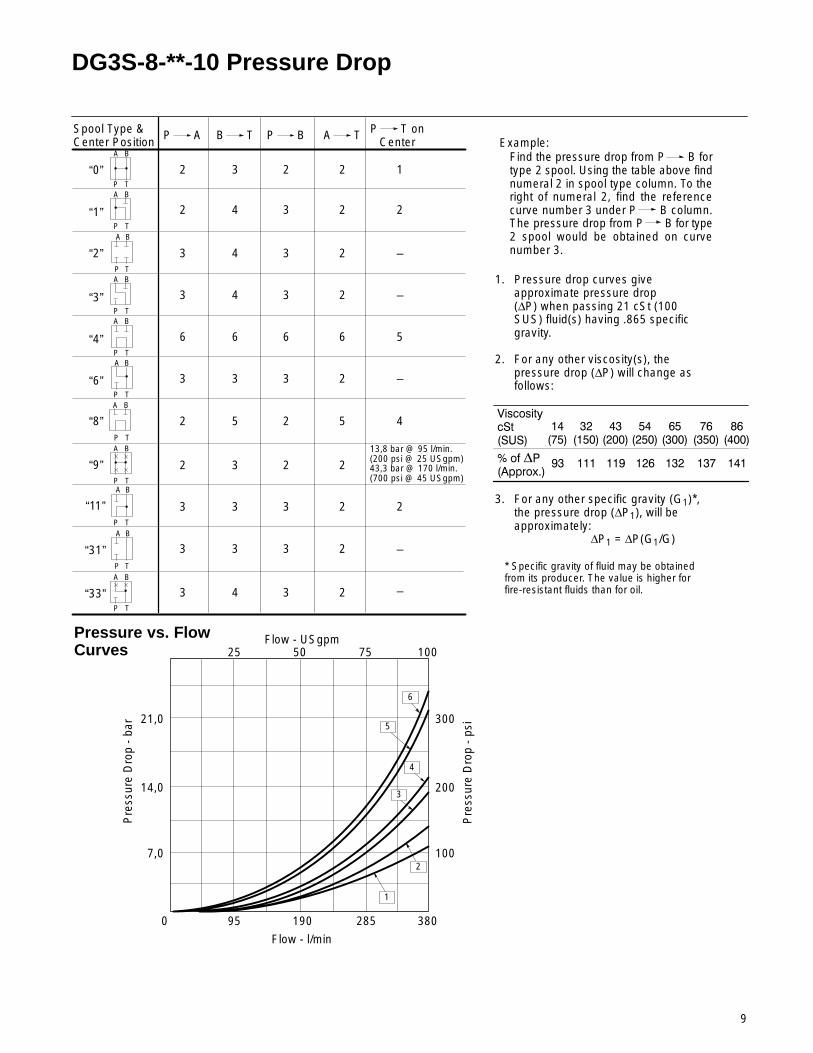
DG3S-8-**-10 Pressure Drop
Pressure vs. Flow Curves
Spool Type &Center Position
P A
1. Pressure drop curves giveapproximate pressure drop(∆P) when passing 21 cSt (100SUS) fluid(s) having .865 specificgravity.
2. For any other viscosity(s), thepressure drop (∆P) will change asfollows:
��� ��� ��� ��� ���
��� ���� ������
������
�������
�������
�������
�������
�������
�������
�����������������
�� ���
3. For any other specific gravity (G1)*,the pressure drop (∆P1), will beapproximately:
∆P1 = ∆P(G1/G)
* Specific gravity of fluid may be obtainedfrom its producer. The value is higher forfire-resistant fluids than for oil.
B T P B A T P T onCenter
A B
P T
“0”
A B
P T
“2”
A B
P T
“3”
A B
P T
“4”
A B
P T
“6”
A B
P T
“8”
A B
P T
“9”
2 3 2 2 1
3 4 3 2 –
3 4 3 2 –
6 6 6 6 5
3 3 3 2 –
2 5 2 5 4
2 3 2 2
Flow - l/min
Flow - USgpm
Pre
ssur
e D
rop
- ba
r
Pre
ssur
e D
rop
- ps
i
0 95 190 285 380
25 50 75 100
100
200
300
7,0
14,0
21,0
Example:Find the pressure drop from P B fortype 2 spool. Using the table above findnumeral 2 in spool type column. To theright of numeral 2, find the referencecurve number 3 under P B column.The pressure drop from P B for type2 spool would be obtained on curvenumber 3.
6
5
4
3
2
1
A B
P T
“1” 2 4 3 2 2
A B
P T
“33” 3 4 3 2
A B
P T
“11” 3 3 3 2 2
A B
P T
“31” 3 3 3 2
13,8 bar @ 95 l/min.(200 psi @ 25 USgpm)43,3 bar @ 170 l/min.(700 psi @ 45 USgpm)
–
–

10
DG3S-8-**-10 Pressure Drop Across Check Valve
Integral Check ValvesThe pilot pressure (refer to pilot pressurechart) is the total of pressure dropthrough valve (P to T) on center frompressure drop vs. flow curve at actualminimum application flow plus pressuredrop through check valve usingappropriate spring model (K, R or S)from check valve pressure drop vs. flowcurve plus other pressure dropsdownstream of valve.
NOTETotal pressure drop must be greaterthan minimum pilot pressurerequired for good machine reliability.
For Other Uses:
A check valve with 0,35 bar (5 psi)cracking pressure model “K” can beused to prevent reverse flow other thanleakage as in clamp circuits and wherethe check is not required for pilotpressure.
Flow - USgpm
Flow - l/min.
Pre
ssur
e D
rop
- ba
r
Pre
ssur
e D
rop
- ps
i
10
8
6
4
2
0 95 190 285 380
25 50 75 100150
100
50
“K” Spring
“R” Spring
“S” Spring
11
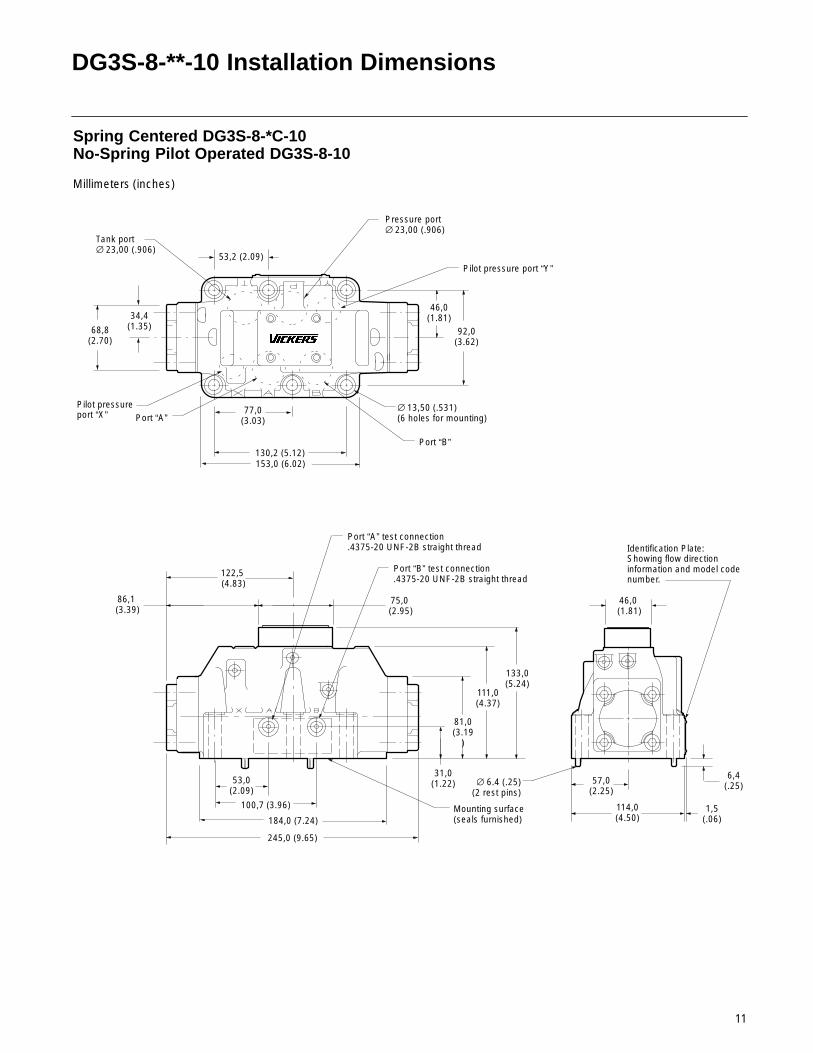
DG3S-8-**-10 Installation Dimensions
46,0 (1.81)
86,1 (3.39)
75,0 (2.95)
122,5 (4.83)
Spring Centered DG3S-8-*C-10No-Spring Pilot Operated DG3S-8-10
Millimeters (inches)
53,0(2.09)
100,7 (3.96)
184,0 (7.24)
245,0 (9.65)
81,0(3.19
)
111,0(4.37)
130,2 (5.12)153,0 (6.02)
53,2 (2.09)
46,0(1.81)
92,0(3.62)
Pressure port∅ 23,00 (.906)
Tank port∅ 23,00 (.906)
Port “B”
Port “A”∅ 13,50 (.531)(6 holes for mounting)
Port “A” test connection.4375-20 UNF-2B straight thread
Port “B” test connection.4375-20 UNF-2B straight thread
Mounting surface(seals furnished)
57,0(2.25)
114,0(4.50)
6,4(.25)
1,5(.06)
∅ 6.4 (.25)(2 rest pins)
77,0(3.03)
31,0(1.22)
Identification Plate:Showing flow directioninformation and model codenumber.
133,0(5.24)
Pilot pressure port “Y”
Pilot pressure port “X”
68,8(2.70)
34,4(1.35)
12
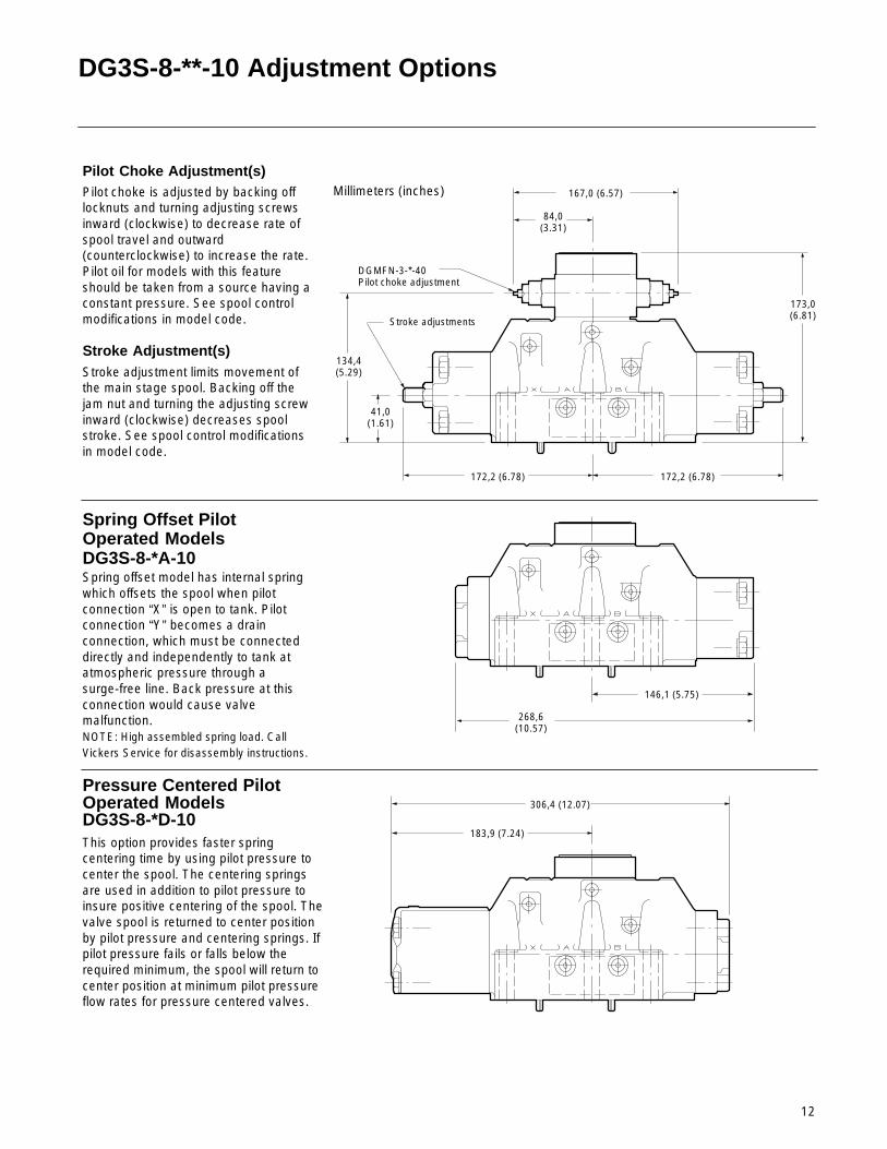
DG3S-8-**-10 Adjustment Options
268,6(10.57)
Millimeters (inches)
Pilot Choke Adjustment(s)Pilot choke is adjusted by backing offlocknuts and turning adjusting screwsinward (clockwise) to decrease rate ofspool travel and outward(counterclockwise) to increase the rate.Pilot oil for models with this featureshould be taken from a source having aconstant pressure. See spool controlmodifications in model code.
Stroke Adjustment(s)Stroke adjustment limits movement ofthe main stage spool. Backing off thejam nut and turning the adjusting screwinward (clockwise) decreases spoolstroke. See spool control modificationsin model code.
172,2 (6.78)
41,0(1.61)
173,0(6.81)
172,2 (6.78)
134,4(5.29)
84,0(3.31)
167,0 (6.57)
DGMFN-3-*-40Pilot choke adjustment
Stroke adjustments
Spring Offset Pilot Operated ModelsDG3S-8-*A-10
146,1 (5.75)
Spring offset model has internal springwhich offsets the spool when pilotconnection “X” is open to tank. Pilotconnection “Y” becomes a drainconnection, which must be connecteddirectly and independently to tank atatmospheric pressure through asurge-free line. Back pressure at thisconnection would cause valvemalfunction.NOTE: High assembled spring load. CallVickers Service for disassembly instructions.
Pressure Centered PilotOperated ModelsDG3S-8-*D-10This option provides faster springcentering time by using pilot pressure tocenter the spool. The centering springsare used in addition to pilot pressure toinsure positive centering of the spool. Thevalve spool is returned to center positionby pilot pressure and centering springs. Ifpilot pressure fails or falls below therequired minimum, the spool will return tocenter position at minimum pilot pressureflow rates for pressure centered valves.
183,9 (7.24)
306,4 (12.07)
13
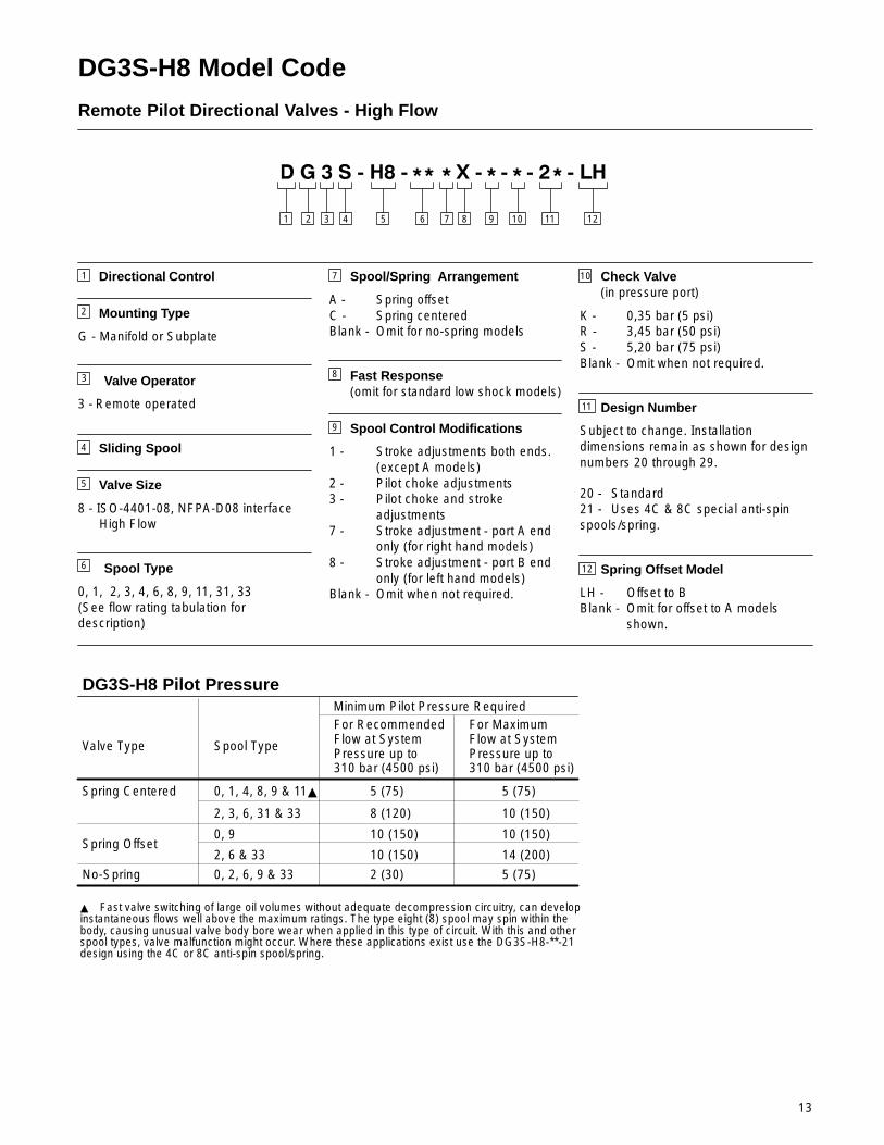
DG3S-H8 Model Code
Remote Pilot Directional Valves - High Flow
2 3 4 765 81 12
1
2
Directional Control
Mounting Type
G - Manifold or Subplate
Valve Operator
3 - Remote operated
Sliding Spool
Valve Size
8 - ISO-4401-08, NFPA-D08 interface High Flow
Spool Type
0, 1, 2, 3, 4, 6, 8, 9, 11, 31, 33(See flow rating tabulation fordescription)
3
4
7
9
8
12
10
11
Spool/Spring Arrangement
A - Spring offsetC - Spring centeredBlank - Omit for no-spring models
Fast Response(omit for standard low shock models)
Spool Control Modifications
1 - Stroke adjustments both ends.(except A models)
2 - Pilot choke adjustments3 - Pilot choke and stroke
adjustments7 - Stroke adjustment - port A end
only (for right hand models)8 - Stroke adjustment - port B end
only (for left hand models)Blank - Omit when not required.
Check Valve(in pressure port)
K - 0,35 bar (5 psi)R - 3,45 bar (50 psi)S - 5,20 bar (75 psi)Blank - Omit when not required.
Design Number
Subject to change. Installationdimensions remain as shown for designnumbers 20 through 29.
20 - Standard21 - Uses 4C & 8C special anti-spinspools/spring.
Spring Offset Model
LH - Offset to BBlank - Omit for offset to A models
shown.
10 11
5
6
9
DG3S-H8 Pilot Pressure
Valve Type Spool Type
Minimum Pilot Pressure RequiredFor Recommended Flow at SystemPressure up to 310 bar (4500 psi)
For Maximum Flow at SystemPressure up to 310 bar (4500 psi)
Spring Centered
No-Spring
Spring Offset
0, 1, 4, 8, 9 & 11�
2, 3, 6, 31 & 33
0, 2, 6, 9 & 33
0, 9
2, 6 & 33
5 (75)
8 (120)
5 (75)
10 (150)
10 (150)
10 (150)
10 (150)
14 (200)
� Fast valve switching of large oil volumes without adequate decompression circuitry, can developinstantaneous flows well above the maximum ratings. The type eight (8) spool may spin within thebody, causing unusual valve body bore wear when applied in this type of circuit. With this and otherspool types, valve malfunction might occur. Where these applications exist use the DG3S-H8-**-21design using the 4C or 8C anti-spin spool/spring.
2 (30) 5 (75)
14
A B
P T
A B
P T
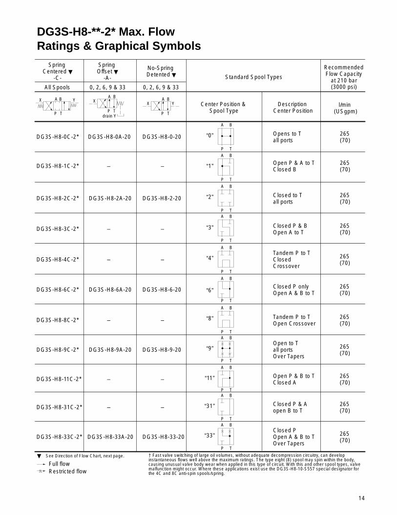
Spring Centered �
-C-
Spring Offset �
-A-
No-Spring Detented �
All Spools 0, 2, 6, 9 & 33
Standard Spool Types
Center Position & Spool Type
Description Center Position
RecommendedFlow Capacity
at 210 bar(3000 psi)
l/min (USgpm)
DG3S-H8-0C-2*
A B
P T
“0”DG3S-H8-0A-20 Opens to Tall ports
265(70)
DG3S-H8-1C-2*
A B
P T
“2”
DG3S-H8-0-20
Open P & A to TClosed B
265(70)
DG3S-H8-2C-2*
A B
P T
“3”
DG3S-H8-2-20
Closed P & Aopen B to T
265(70)
DG3S-H8-3C-2*
A B
P T
“4”
Closed P & BOpen A to T
265(70)
DG3S-H8-4C-2*
A B
P T
“6”
Tandem P to TClosedCrossover
DG3S-H8-6C-2*
A B
P T
“8”
DG3S-H8-6-20 Closed P onlyOpen A & B to T
DG3S-H8-8C-2*
A B
P T
“33”
Tandem P to TOpen Crossover
Full flowRestricted flow
� See Direction of Flow Chart, next page.
X Y X A B
P T
X
drain Y
Y
0, 2, 6, 9 & 33
DG3S-H8-9C-2*
DG3S-H8-11C-2*
DG3S-H8-31C-2*
DG3S-H8-33C-2*
DG3S-H8-2A-20
DG3S-H8-6A-20
DG3S-H8-9A-20
DG3S-H8-33A-20
DG3S-H8-9-20
DG3S-H8-33-20
A B
P T
“1”
A B
P T
“9”
A B
“11”
P TA B
P T
“31”
Closed to Tall ports
Open to T all ports Over Tapers
Open P & B to TClosed A
Closed POpen A & B to TOver Tapers
265(70)
� Fast valve switching of large oil volumes, without adequate decompression circuitry, can developinstantaneous flows well above the maximum ratings. The type eight (8) spool may spin within the body,causing unusual valve body wear when applied in this type of circuit. With this and other spool types, valvemalfunction might occur. Where these applications exist use the DG3S-H8-10-S557 special designator forthe 4C and 8C anti-spin spools/spring.
DG3S-H8-**-2* Max. FlowRatings & Graphical Symbols
– –
– –
– –
– –
– –
– –
265(70)
265(70)
265(70)
265(70)
265(70)
265(70)
15
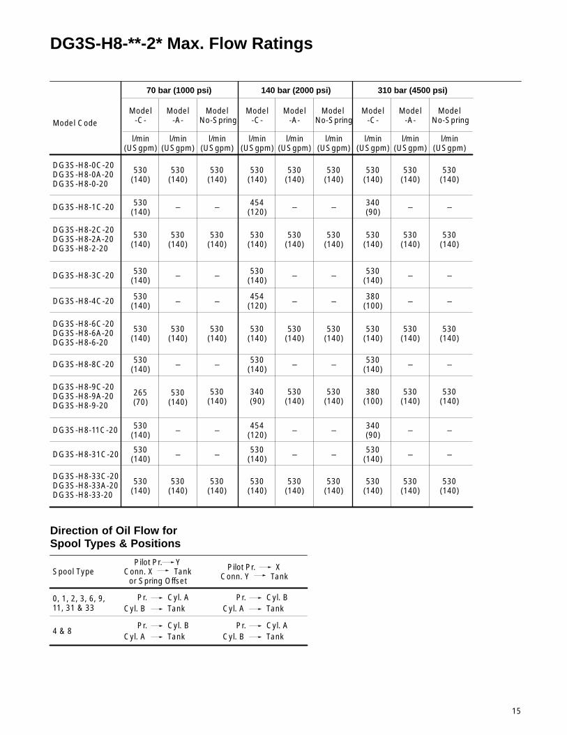
DG3S-H8-**-2* Max. Flow Ratings
DG3S-H8-0C-20DG3S-H8-0A-20DG3S-H8-0-20
Model Code
70 bar (1000 psi) 140 bar (2000 psi) 310 bar (4500 psi)
Model-C-
Model-A-
Model No-Spring
l/min(USgpm)
l/min(USgpm)
l/min(USgpm)
Model-C-
Model-A-
l/min(USgpm)
l/min(USgpm)
l/min(USgpm)
Model-C-
Model-A-
l/min(USgpm)
l/min(USgpm)
l/min(USgpm)
530(140)
530(140)
530(140)
530(140)
530(140)
530(140)
530(140)
530(140)
530(140)
DG3S-H8-1C-20 530(140)
454(120)
340(90)
DG3S-H8-2C-20DG3S-H8-2A-20DG3S-H8-2-20
530(140)
530(140)
530(140)
530(140)
530(140)
530(140)
530(140)
DG3S-H8-3C-20 530(140)
– – –
DG3S-H8-4C-20 530(140)
454(120)
380(100)
DG3S-H8-6C-20DG3S-H8-6A-20DG3S-H8-6-20
530(140)
530(140)
530(140)
530(140)
DG3S-H8-11C-20 530(140)
454(120)
340(90)
Direction of Oil Flow forSpool Types & Positions
Spool TypePilot Pr. Y
Conn. X Tankor Spring Offset
Pilot Pr. XConn. Y Tank
Cyl. A0, 1, 2, 3, 6, 9, 11, 31 & 33
4 & 8
Pr.TankCyl. B
Cyl. BPr.TankCyl. A
Cyl. BPr.TankCyl. A
Cyl. APr.TankCyl. B
Model No-Spring
Model No-Spring
– – –
530(140)
530(140)
– – –
530(140)
– – –
DG3S-H8-31C-20 530(140)
530(140)
530(140)– – –
DG3S-H8-33C-20DG3S-H8-33A-20DG3S-H8-33-20
530(140)
530(140)
530(140)
530(140)
530(140)
530(140)
530(140)
DG3S-H8-8C-20 530(140)
530(140)
530(140)
– – –
DG3S-H8-9C-20DG3S-H8-9A-20DG3S-H8-9-20
530(140)
530(140)
380(100)
530(140)
530(140)
– – –
– – –530(140)
530(140)
– – –
530(140)
530(140)
530(140)
530(140)
– – –
265(70)
530(140)
340(90)
530(140)
530(140)
– – –
– – –
530(140)
16
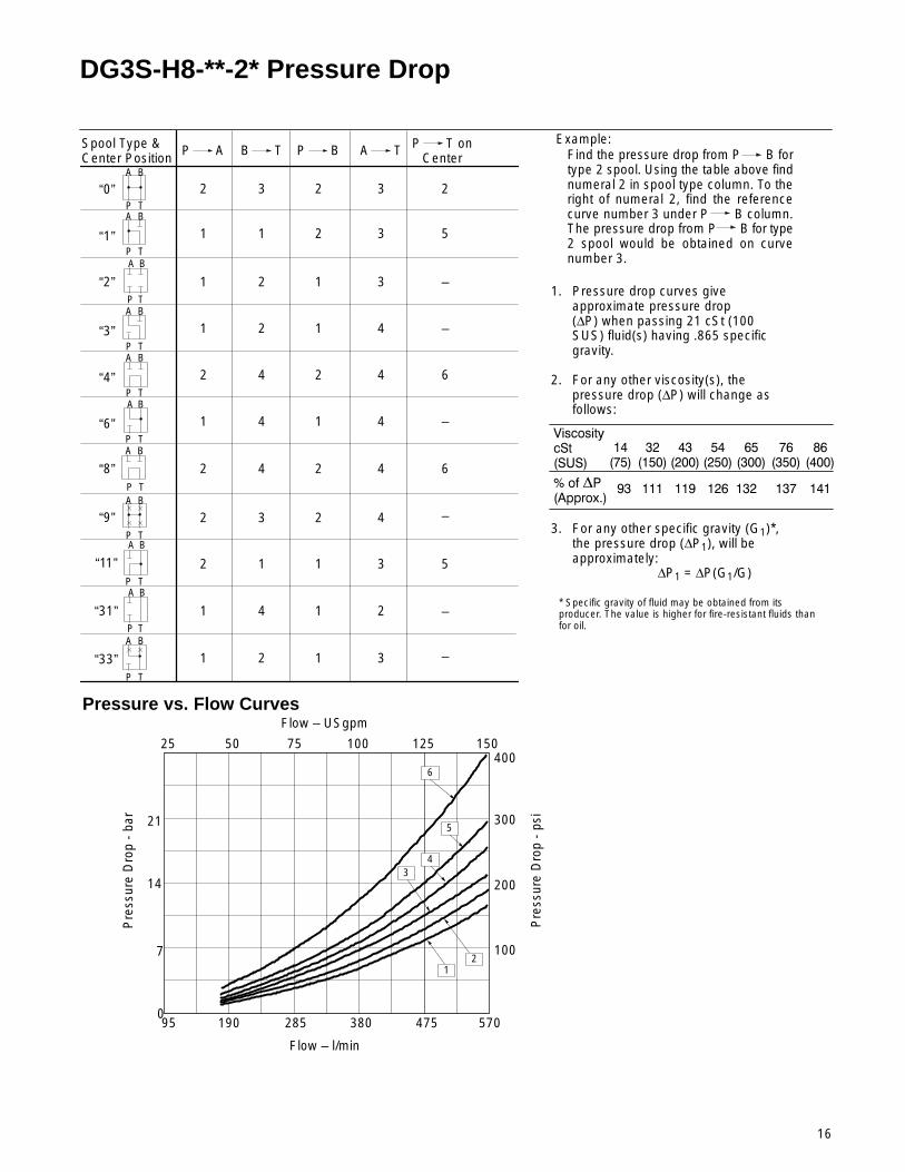
DG3S-H8-**-2* Pressure Drop
Pressure vs. Flow Curves
Spool Type &Center Position
P A
1. Pressure drop curves giveapproximate pressure drop(∆P) when passing 21 cSt (100SUS) fluid(s) having .865 specificgravity.
2. For any other viscosity(s), thepressure drop (∆P) will change asfollows:
��� ��� ��� ��� ���
��� ���� ������
������
�������
�������
�������
�������
�������
�������
�����������������
�� ���
3. For any other specific gravity (G1)*,the pressure drop (∆P1), will beapproximately:
∆P1 = ∆P(G1/G)
* Specific gravity of fluid may be obtained from itsproducer. The value is higher for fire-resistant fluids thanfor oil.
B T P B A T P T onCenter
A B
P T
“0”
A B
P T
“2”
A B
P T“3”
A B
P T“4”
A B
P T“6”
A B
P T
“8”
A B
P T
“9”
2 3 2 3 2
1 2 1 3 –
1 2 1 4 –
2 4 2 4 6
1 4 1 4 –
2 4 2 4 6
2 3 2 4
Example:Find the pressure drop from P B fortype 2 spool. Using the table above findnumeral 2 in spool type column. To theright of numeral 2, find the referencecurve number 3 under P B column.The pressure drop from P B for type2 spool would be obtained on curvenumber 3.
A B
P T“1” 1 1 2 3 5
A B
P T
“33” 1 2 1 3
A B
P T
“11” 2 1 1 3 5
A B
P T
“31” 1 4 1 2 –
–
–
25 50 75 100
7
14
21
095 190 285 380
Flow – USgpm
Flow – l/min
Pre
ssur
e D
rop
- ba
r
125
100
475
200
300
Pre
ssur
e D
rop
- ps
i
150
570
4006
5
43
21
17
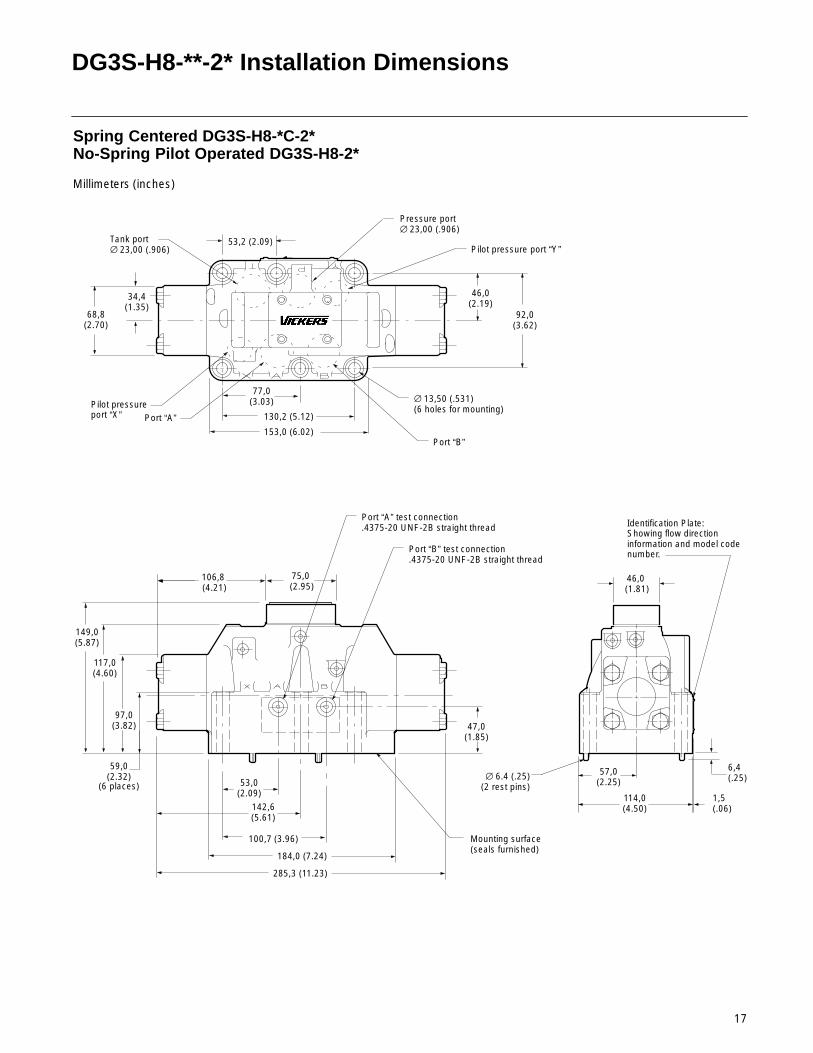
DG3S-H8-**-2* Installation Dimensions
59,0(2.32)
97,0(3.82)
117,0(4.60)
75,0 (2.95)
46,0 (1.81)
106,8 (4.21)
Spring Centered DG3S-H8-*C-2*No-Spring Pilot Operated DG3S-H8-2*
Millimeters (inches)
53,0(2.09)
100,7 (3.96)
184,0 (7.24)
285,3 (11.23)
130,2 (5.12)
153,0 (6.02)
53,2 (2.09)
92,0(3.62)
Pressure port∅ 23,00 (.906)
Tank port∅ 23,00 (.906)
Port “B”
Port “A”
∅ 13,50 (.531)(6 holes for mounting)
Port “A” test connection.4375-20 UNF-2B straight thread
Port “B” test connection.4375-20 UNF-2B straight thread
Mounting surface(seals furnished)
57,0(2.25)
114,0(4.50)
6,4(.25)
1,5(.06)
∅ 6.4 (.25)(2 rest pins)
77,0(3.03)
47,0(1.85)
Identification Plate:Showing flow directioninformation and model codenumber.
Pilot pressure port “Y”
Pilot pressure port “X”
68,8(2.70)
34,4(1.35)
46,0(2.19)
142,6(5.61)
149,0(5.87)
(6 places)
18
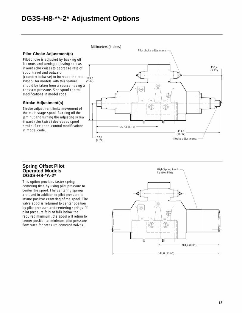
DG3S-H8-**-2* Adjustment Options
57,0(2.24)
189,0(7.44)
Millimeters (inches)
Pilot Choke Adjustment(s)Pilot choke is adjusted by backing offlocknuts and turning adjusting screwsinward (clockwise) to decrease rate ofspool travel and outward(counterclockwise) to increase the rate.Pilot oil for models with this featureshould be taken from a source having aconstant pressure. See spool controlmodifications in model code.
Stroke Adjustment(s)Stroke adjustment limits movement ofthe main stage spool. Backing off thejam nut and turning the adjusting screwinward (clockwise) decreases spoolstroke. See spool control modificationsin model code.
207,3 (8.16)
150,4(5.92)
414,6(16.32)
Pilot choke adjustments
Stroke adjustments
Spring Offset Pilot Operated ModelsDG3S-H8-*A-2*This option provides faster springcentering time by using pilot pressure tocenter the spool. The centering springsare used in addition to pilot pressure toinsure positive centering of the spool. Thevalve spool is returned to center positionby pilot pressure and centering springs. Ifpilot pressure fails or falls below therequired minimum, the spool will return tocenter position at minimum pilot pressureflow rates for pressure centered valves.
204,4 (8.05)
347,0 (13.66)
High Spring Load Caution Plate
19
DG3S-H8-**-2* Pressure Drop Across Check Valve
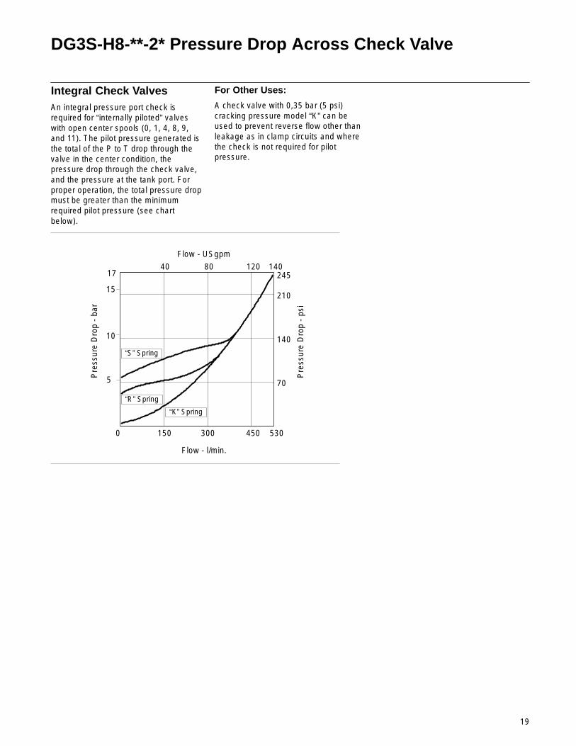
Integral Check ValvesAn integral pressure port check isrequired for “internally piloted” valveswith open center spools (0, 1, 4, 8, 9,and 11). The pilot pressure generated isthe total of the P to T drop through thevalve in the center condition, thepressure drop through the check valve,and the pressure at the tank port. Forproper operation, the total pressure dropmust be greater than the minimumrequired pilot pressure (see chartbelow).
For Other Uses:
A check valve with 0,35 bar (5 psi)cracking pressure model “K” can beused to prevent reverse flow other thanleakage as in clamp circuits and wherethe check is not required for pilotpressure.
Flow - USgpm
Flow - l/min.
Pre
ssur
e D
rop
- ba
r
Pre
ssur
e D
rop
- ps
i
“K” Spring
“R” Spring
“S” Spring
17
15
10
5
0 150 300 450
40 80 120 140
210
245
70
140
530

20
DG3S-(H)8-**-10/2* Subplates & Bolt Kits
Valves, subplates and mounting boltsmust be ordered separately.
Example:(1) DG3S-(H)8-2C-10/2* Valve(1) DGSM-8-10-T12 Subplate(1) BKDGH06-618 Inch Bolt Kit or(1) BKDGH8-655M Metric Bolt Kit
When subplate is not used, a machinedpad must be provided for mounting. Padmust be flat within 0,0127 mm (.0005inch) and smooth within 1,6 µm (63microinch). Mounting bolts, whenprovided by customer, should be SAEgrade 7 or better.
DGSM-8-10-T12/16Mounting Subplates
92,2(3.63)
4,87(0.19)
11,0(0.43)
29,5(1.16)
19,1(0.75)
17,5(0.69)
73,1(2.88)
180,9(7.12)
11,0(0.43)
203(7.99)
35(1.38)
77,1(3.04)
112,8(4.44)
112,8(4.44)
94,6(3.72)
DGSM-8-10-T12: Cyl. conn. “B” ∅ 23,8 (.94) thru SAE str. thd. 1.0625-12 UN-2B thd.Tubing O.D. .750 DGSM-8-10-T16: Cyl. conn. “B” ∅ 24,6 (.97) thru SAE str. thd.1.3125-12 UN-2B thd. Tubing O.D. 1.00
∅ 10,3 (.406) -4 holes for mounting
“T” Tank conn.
“P” Pressure inlet conn.
“A” Cyl. conn.
“X” External pilot pressure conn.∅12,9 (.508) thru. .5625-18 UNF-2B thd. For.375 O.D. tubing from rear - 2 holes, “X” & “Y”
“Y” Pilot valve drain conn.(For externally drained pilotvalves) and drain conn.
.500-13 UNC-2B thd 6 holes (subplate with M12x 1.75 metric screw holesavailable on request.
DGSM-8-10-T20 Mounting Subplate
146(5.75)
167,8(6.61)116
(4.57)
12,7(.50)
19,1(.75)
94,6(3.72)
193,5(7.62)
14,4(.55)
29,5(1.16)
55,3(2.18) 77,1
(3.04)100,9(3.97) 130,3
(5.13)
17,5(.69)
73,1(2.88)
74,7(2.94)
43,7(1.72)
100,8(3.97)
126,2(4.97)
25,4(1.00)
65,9(2.59)
120,7(4.75)
97(3.81)
92,2(3.63)
19,1(.75)
14,3(.56)
“A” Cyl. conn.
“B” Cyl. conn.
“P” Pressure inlet conn.
“T” Tank conn.
∅ 10,3 (.406), 4 holes for mounting
“Y” Pilot valve drain conn.(For externally drained pilotvalves) and drain conn.
“X” External pilot pressure conn.
DGSM-8-10-T20: SAE str. thd. 1.6250-12 Tubing O.D. 1.250
21
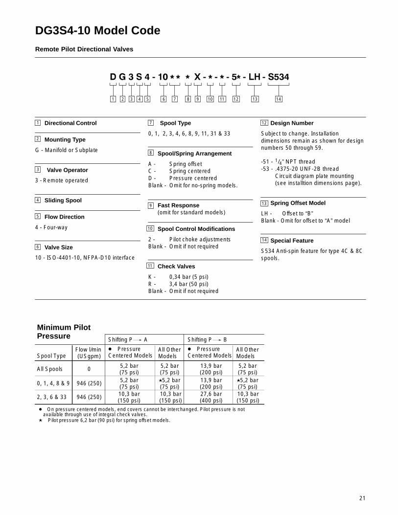
DG3S4-10 Model Code Remote Pilot Directional Valves
2 3 4 7651 10
1
2
Directional Control
Mounting Type
G - Manifold or Subplate
Valve Operator
3 - Remote operated
Sliding Spool
Flow Direction
4 - Four-way
Valve Size
10 - ISO-4401-10, NFPA-D10 interface
3
4
7
8
9
14
13
Spool Type
0, 1, 2, 3, 4, 6, 8, 9, 11, 31 & 33
Spool/Spring Arrangement
A - Spring offsetC - Spring centeredD - Pressure centeredBlank - Omit for no-spring models.
Fast Response(omit for standard models)
Spool Control Modifications
2 - Pilot choke adjustmentsBlank - Omit if not required
Check Valves
K - 0,34 bar (5 psi)R - 3,4 bar (50 psi)Blank - Omit if not required
Design Number
Subject to change. Installationdimensions remain as shown for designnumbers 50 through 59.
-51 - 1/4” NPT thread-53 - .4375-20 UNF-2B thread
Circuit diagram plate mounting (see installtion dimensions page).
Spring Offset Model
LH - Offset to “B”Blank - Omit for offset to “A” model
Special Feature
S534 Anti-spin feature for type 4C & 8Cspools.
8 11 12 13
5
6
10
12
9
Minimum PilotPressure
Spool TypeFlow l/min (USgpm)
Shifting P A Shifting P B
All Spools 0
� Pressure Centered Models
All OtherModels
� Pressure Centered Models
All OtherModels
5,2 bar(75 psi)
5,2 bar(75 psi)
13,9 bar(200 psi)
5,2 bar(75 psi)
0, 1, 4, 8 & 9 946 (250) 5,2 bar(75 psi)
�5,2 bar(75 psi)
13,9 bar(200 psi)
�5,2 bar(75 psi)
2, 3, 6 & 33 946 (250) 10,3 bar(150 psi)
10,3 bar(150 psi)
27,6 bar(400 psi)
10,3 bar(150 psi)
� On pressure centered models, end covers cannot be interchanged. Pilot pressure is not available through use of integral check valves.� Pilot pressure 6,2 bar (90 psi) for spring offset models.
14
11

22
DG3S4-10**-5* Ratings
Pressure Drop
Spool Type P to A B to T P to B A to T
3,1 bar(45 psi)
1. Figures in the pressure drop chartgive approximate pressure drops(∆P) when passing 473 l/min (125 USgpm) flow (Q) of 100 SUSfluid(s) having .865 specific gravity.
2. For any other flow rate (Q1), thepressure drop (∆P1) will beapproximately:
∆P1 = ∆P(Q1/Q2)2 3. For any other viscosity(s), the
pressure drop (∆P) will change asfollows:
��� ��� ��� ��� ���
��� ���� ������
������
�������
�������
�������
�������
�������
�������
�����������������
�� ���
4. For any other specific gravity (G1)*,the pressure drop (∆A1), will beapproximately:
∆P1 = ∆P(G1/G)* Specific gravity of fluid may be obtained from its producer.The value is higher for fire-resistant fluids than for oil.
3,8 bar(55 psi)
3,8 bar(55 psi)
5,7 bar(83 psi)
5,2 bar(76 psi)
P to TCentered
0 5,0 bar(73 psi)
3,5 bar(51 psi)
4,5 bar(65 psi)
3,8 bar(55 psi)
2
3,8 bar(55 psi)
3,8 bar(55 psi)
5,7 bar(83 psi)
3,3 bar(48 psi)
3
5,5 bar(80 psi)
5,5 bar(80 psi)
10,3 bar(150 psi)
11,7 bar(170 psi)
4
3,8 bar(55 psi)
3,8 bar(55 psi)
5,2 bar(75 psi)
3,2 bar(46 psi)
6
4,3 bar(62 psi)
4,3 bar(63 psi)
8,4 bar(122 psi)
9,5 bar(138 psi)
8
3,2 bar(46 psi)
3,4 bar(50 psi)
5,2 bar(75 psi)
4,8 bar(70 psi)
9
3,8 bar(55 psi)
3,8 bar(55 psi)
5,7 bar(83 psi)
5,2 bar(76 psi)
33
27,6 bar(400 psi)
473 l/min (125 USgpm)
5,5 bar(80 psi)
5,5 bar(80 psi)
Flow Ratings
Valve Type Spool Type RecommendedFlow Capacity
Maximum Flow withoutMalfunction
No Spring 0, 2, 6 & 9 473 l/min
(125 USgpm)946 l/min (250 USgpm)
at 207 bar (3000 psi)
Spring Centered
0, 4 & 8 �
2, 3, 6 & 33
9 378 l/min (100 USgpm)
378 l/min (100 USgpm) at 207 bar (3000 psi)
473 l/min (125 USgpm) at 138 bar (2000 psi)
568 l/min (150 USgpm) at 69 bar (1000 psi)
946 l/min (250 USgpm) at 207 bar (3000 psi)
473 l/min (125 USgpm)
757 l/min (200 USgpm) at 207 bar (3000 psi)
757 l/min (200 USgpm) at 69 bar (1000 psi)
757 l/min (200 USgpm) at 138 bar (2000 psi)
0
2
6
9
0, 1, 2, 3, 4, 6, 8, 9 & 33
473 l/min (125 USgpm)
Spring Offset
Pressure Centered
946 l/min (250 USgpm) at 207 bar (3000 psi)
As system flow increases the minimum pilot pressure required increases. These spools willoperate satisfactorily in excess of 946 l/min (250 USgpm) with higher pilot pressures.
� Fast valve switching of large oil volumes, without adequate decompression circuitry, candevelop instantaneous flows well above the maximum ratings. The type “8” spool may spin withinthe body, causing unusual valve body bore wear when applied in this type of circuit. With this andother spool types, valve malfunction might occur. Where these applications exist, use theDG3S4-10-5*-S534 special designator for the 4C and 8C anti-spin spool/spring.
2,5 bar(36 psi)
2,3 bar(34 psi)
4,0 bar(58 psi)
2,1 bar(30 psi)
1 3,2 bar(47 psi)
23
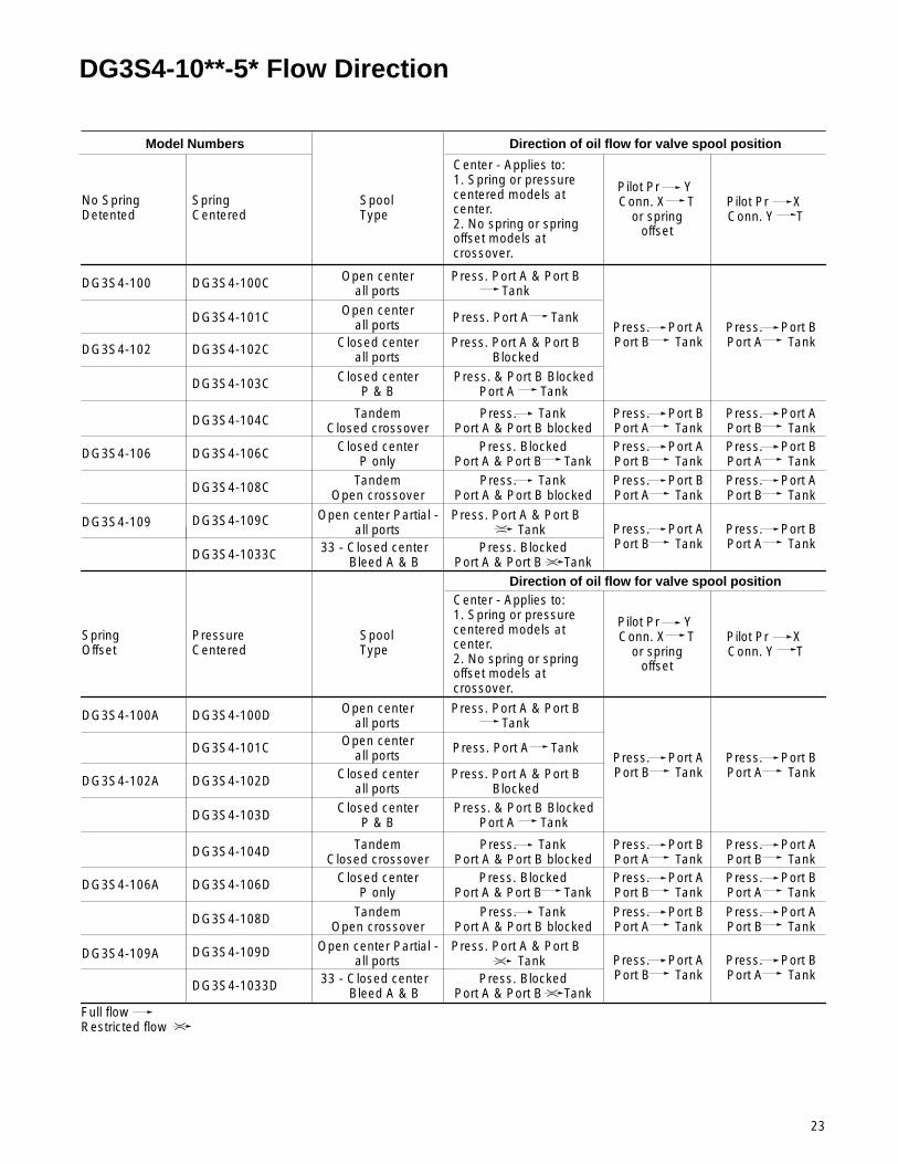
DG3S4-10**-5* Flow Direction
Model Numbers
No Spring Detented
Spring Centered
SpoolType
Direction of oil flow for valve spool position
Pilot Pr Y Conn. X T
or springoffset
DG3S4-100 DG3S4-100C Open centerall ports
DG3S4-102 DG3S4-102C Closed centerall ports
Center - Applies to:1. Spring or pressurecentered models atcenter.2. No spring or springoffset models atcrossover.
Press. Port A & Port BTank
DG3S4-104C TandemClosed crossover
DG3S4-106 DG3S4-106C Closed centerP only
DG3S4-108C TandemOpen crossover
DG3S4-1033C 33 - Closed center Bleed A & B
Press. TankPort A & Port B blocked
Press. Port A & Port BBlocked
Press. BlockedPort A & Port B Tank
Press. TankPort A & Port B blocked
Press. BlockedPort A & Port B Tank
Press. Port APort B Tank
Press. Port BPort A Tank
Press. Port APort B Tank
Press. Port BPort A TankPress. Port APort B Tank
Press. Port BPort A Tank
Press. Port BPort A Tank
Press. Port APort B Tank
Press. Port APort B Tank
Press. Port BPort A Tank
Pilot Pr X Conn. Y T
Closed centerP & B
Open center Partial -all ports
Press. & Port B BlockedPort A Tank
Press. Port A & Port B Tank
DG3S4-109
DG3S4-103C
DG3S4-109C
Spring Offset
PressureCentered
SpoolType
Pilot Pr Y Conn. X T
or springoffset
DG3S4-100A DG3S4-100D Open centerall ports
DG3S4-102A DG3S4-102D Closed centerall ports
Center - Applies to:1. Spring or pressurecentered models atcenter.2. No spring or springoffset models atcrossover.
Press. Port A & Port BTank
DG3S4-104D TandemClosed crossover
DG3S4-106A DG3S4-106D Closed centerP only
DG3S4-108D TandemOpen crossover
DG3S4-1033D 33 - Closed center Bleed A & B
Press. TankPort A & Port B blocked
Press. Port A & Port BBlocked
Press. BlockedPort A & Port B Tank
Press. TankPort A & Port B blocked
Press. BlockedPort A & Port B Tank
Press. Port APort B Tank
Press. Port BPort A Tank
Press. Port APort B Tank
Press. Port BPort A TankPress. Port APort B Tank
Press. Port BPort A Tank
Press. Port BPort A Tank
Press. Port APort B Tank
Press. Port APort B Tank
Press. Port BPort A Tank
Pilot Pr X Conn. Y T
Closed centerP & B
Open center Partial -all ports
Press. & Port B BlockedPort A Tank
Press. Port A & Port B TankDG3S4-109A
DG3S4-103D
DG3S4-109D
Full flowRestricted flow
DG3S4-101C Open centerall ports
Press. Port A Tank
Direction of oil flow for valve spool position
DG3S4-101C Open centerall ports
Press. Port A Tank
24
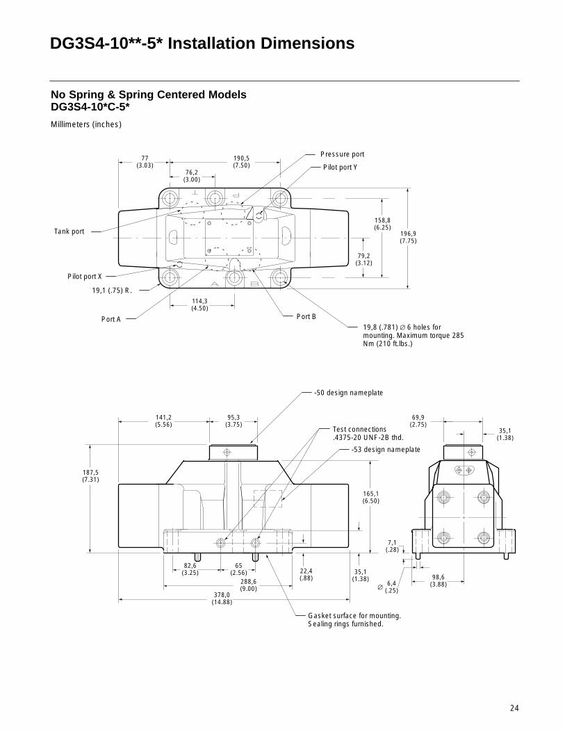
DG3S4-10**-5* Installation Dimensions
190,5(7.50)
378,0(14.88)
76,2(3.00)
No Spring & Spring Centered ModelsDG3S4-10*C-5*
Millimeters (inches)
79,2(3.12)
158,8(6.25)
114,3(4.50)
Pressure port
19,8 (.781) ∅ 6 holes formounting. Maximum torque 285Nm (210 ft.lbs.)
Tank port
Port A Port B
187,5(7.31)
196,9(7.75)
288,6(9.00)
65(2.56)
82,6(3.25) 22,4
(.88)35,1
(1.38)
165,1(6.50)
98,6(3.88)6,4
(.25)∅
7,1(.28)
Test connections.4375-20 UNF-2B thd.
Gasket surface for mounting.Sealing rings furnished.
19,1 (.75) R.
77(3.03)
141,2(5.56)
95,3(3.75)
69,9(2.75)
35,1(1.38)
Pilot port X
Pilot port Y
-53 design nameplate
-50 design nameplate

25
DG3S4-102*-5* Adjustment Options
Millimeters (inches)Pilot Choke AdjustmentDG3S4-102C-2-5*Pilot choke is adjusted by backing offlocknuts and turning adjusting screwsinward (clockwise) to decrease rate ofspool travel and outward(counterclockwise) to increase the rate.Pilot oil for models with this featureshould be taken from a source having aconstant pressure. See spool controlmodifications in model code.
22,1(.87)
238(9.37)
Pilot choke adjustment
Pressure Centered ModelsDG3S4-102D-5*This option provides faster springcentering time by using pilot pressure tocenter the spool. The centering springsare used in addition to pilot pressure toinsure positive centering of the spool. Thevalve spool is returned to center positionby pilot pressure and centering springs. Ifpilot pressure fails or falls below therequired minimum of 10,3 bar (150 psi)the spool will return to center position atminimum pilot pressure flow rates forpressure centered valves.
209,6(8.25)
Nut 13,0 (.51)
across flats
Screwdriver slot
50,8(2.00)
187,5(7.38)
423,2(16.66)
Spring Offset ModelsDG3S4-102A-5*Spring offset model has internal springwhich offsets the spool when pilotconnection “X” is open to tank. Pilotconnection “Y” becomes a drainconnection, which must be connecteddirectly and independently to tank atatmospheric pressure through asurge-free line. Back pressure at thisconnection would cause valvemalfunction.NOTE: High assembled spring load. CallVickers Service for disassembly instructions.

26
DG3S4-10**-5* Subplate & Bolt Kits
Subplates & Bolt KitsValves, subplates and mounting boltsmust be ordered separately.
Example:One (1) DG3S-102C-5* ValveOne (1) DGSM-10-24S-11 SubplateOne (1) BKDG10-636 Bolt Kit
(bolt length 69,9 (2.75)
When subplate is not used, a machinedpad (as indicated by subplate shadedarea, below, must be provided formounting. Pad must be flat within 0,0127mm (.0005 inch) and smooth within 1,6µm (63 microinch). Mounting bolts, whenprovided by customer, should be SAEgrade 7 or better.
ÇÇÇÇÇÇÇÇÇÇÇÇÇÇÇÇÇÇÇÇÇÇÇÇÇÇÇÇÇÇÇÇÇÇÇÇÇÇÇÇÇÇÇÇÇÇÇÇÇÇÇÇÇÇÇÇÇÇÇÇÇÇÇÇÇÇÇÇÇÇÇÇÇÇÇÇÇÇÇÇ
Mounting SubplateDGSM-10(*) -11
“P” – Pressure inlet connection
∅16,7 (.656) (4 holes for mounting)
Port connection B
304,8 (12.0) 266,7
(10.5)190,5 (7.50)
147,6(5.81)
82,6(3.25)
158,8(6.25)
41,1(1.62)
114,3(4.50)
44,5(1.75)
22,9(.90)
196,9(7.75)
25,4(1.00)
Port connection A
∅7,1 (.281) - 7,9 (.31) deep (2 holes for rest pins)
.750-10 UNC-2B thd(6 holes)
“T” Tank connection ∅28,6(1.125) (4 holes) - system ports1.875-12 UN-2B thd. (from rear)(4 holes) - system connections.DG3M-10-11 1 1/4” NPT thd.DGSM-10X-11 1 1/2” NPT thd.DGSM-10Y-11 2” NPT thd.
9,5 (.375) drill 26,2 (1.03) deep
28,6 (1.125) drill 22,4 (.88) deep(4 holes)
Manifolds or other mounting interface can be drilled to 33,3 (1.312) dia. Fitting size and fittingspacing limit the subplate port size to 28,6 (1.125) dia.
19,1 (.75) R.
114(4.47)
124(4.88)
130(5.12)
26,9 (1.06)
130(5.12)
160,3(6.31)
22,4(.88)
35,1(1.38)
39,6(1.56)
27
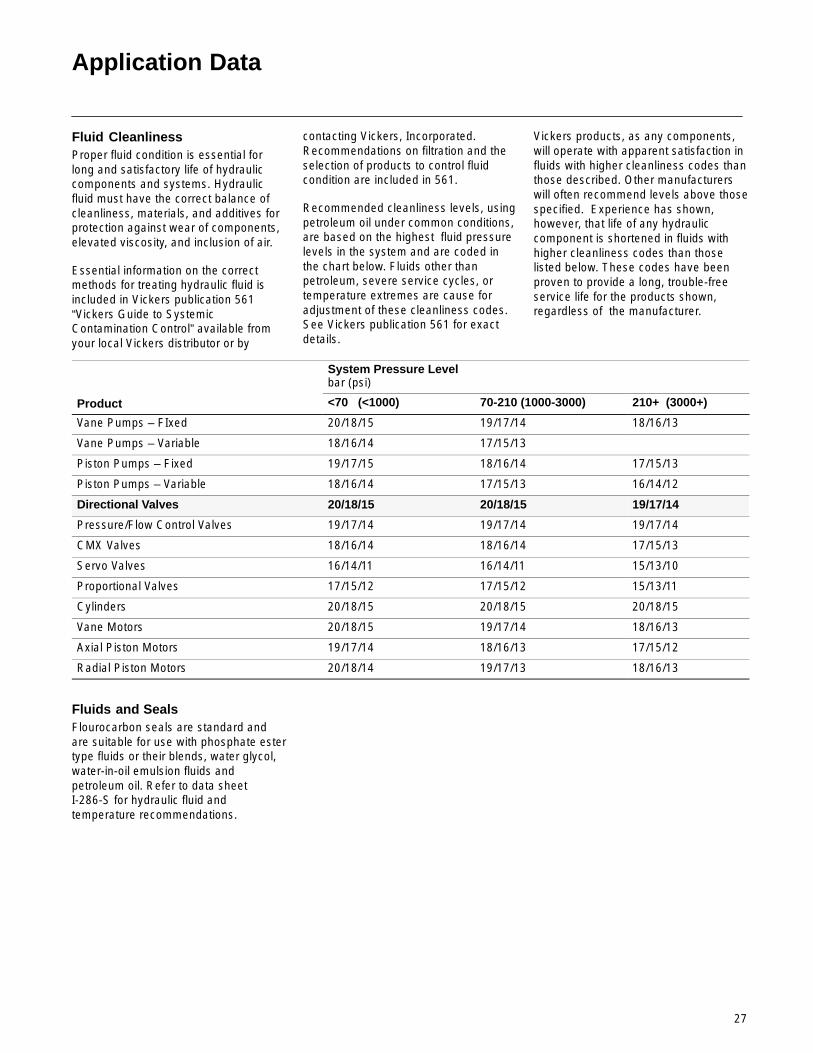
Application Data
Fluid CleanlinessProper fluid condition is essential forlong and satisfactory life of hydrauliccomponents and systems. Hydraulicfluid must have the correct balance ofcleanliness, materials, and additives forprotection against wear of components,elevated viscosity, and inclusion of air.
Essential information on the correctmethods for treating hydraulic fluid isincluded in Vickers publication 561“Vickers Guide to SystemicContamination Control” available fromyour local Vickers distributor or by
contacting Vickers, Incorporated.Recommendations on filtration and theselection of products to control fluidcondition are included in 561.
Recommended cleanliness levels, usingpetroleum oil under common conditions,are based on the highest fluid pressurelevels in the system and are coded inthe chart below. Fluids other thanpetroleum, severe service cycles, ortemperature extremes are cause foradjustment of these cleanliness codes.See Vickers publication 561 for exactdetails.
Vickers products, as any components,will operate with apparent satisfaction influids with higher cleanliness codes thanthose described. Other manufacturerswill often recommend levels above thosespecified. Experience has shown,however, that life of any hydrauliccomponent is shortened in fluids withhigher cleanliness codes than thoselisted below. These codes have beenproven to provide a long, trouble-freeservice life for the products shown,regardless of the manufacturer.
System Pressure Levelbar (psi)
Product <70 (<1000) 70-210 (1000-3000) 210+ (3000+)
Vane Pumps – FIxed 20/18/15 19/17/14 18/16/13
Vane Pumps – Variable 18/16/14 17/15/13
Piston Pumps – Fixed 19/17/15 18/16/14 17/15/13
Piston Pumps – Variable 18/16/14 17/15/13 16/14/12
Directional Valves 20/18/15 20/18/15 19/17/14
Pressure/Flow Control Valves 19/17/14 19/17/14 19/17/14
CMX Valves 18/16/14 18/16/14 17/15/13
Servo Valves 16/14/11 16/14/11 15/13/10
Proportional Valves 17/15/12 17/15/12 15/13/11
Cylinders 20/18/15 20/18/15 20/18/15
Vane Motors 20/18/15 19/17/14 18/16/13
Axial Piston Motors 19/17/14 18/16/13 17/15/12
Radial Piston Motors 20/18/14 19/17/13 18/16/13
Fluids and SealsFlourocarbon seals are standard andare suitable for use with phosphate estertype fluids or their blends, water glycol,water-in-oil emulsion fluids andpetroleum oil. Refer to data sheetI-286-S for hydraulic fluid andtemperature recommendations.