Embed Size (px)
Citation preview
ELECTRONICSPULSE-WIDTH MODULATION
GHI Electronics, LLC - Where Hardware Meets Software

BrainPad – Electronics – Pulse-Width Modulation
Contents
Introduction.......................................................................................................................2
Overview.........................................................................................................................2
Guidelines.......................................................................................................................2
Energy Levels......................................................................................................................3
DC Motor Speed Control.................................................................................................7
Exercise...........................................................................................................................8
Sounds................................................................................................................................ 9
Melodies.......................................................................................................................11
Exercise.........................................................................................................................12
Servo Motors....................................................................................................................13
Exercise.........................................................................................................................15
Page 1 of 17
BrainPad – Electronics – Pulse-Width Modulation
Introduction
The BrainPad circuit board is designed as a powerful educational tool that can be used to teach everyone from kids, to college students and professionals. Kids will start to learn programming using Visual Studio, one of the most widely used professional tools. College students and professionals that already know programming can use the BrainPad circuit board to learn about digital electronics and the connection between computing and the physical world.
Overview
Students will learn how PWM (Pulse-Width Modulation) is a powerful feature found in every microcontroller. This includes how to control power levels, servo motors and sounds.
Guidelines
Prerequisites: EL102 Ages 12 and up PC setup with Visual Studio, .NET Micro Framework and GHI Electronics’
software. Supplies: BrainPad
Page 2 of 17
BrainPad – Electronics – Pulse-Width Modulation
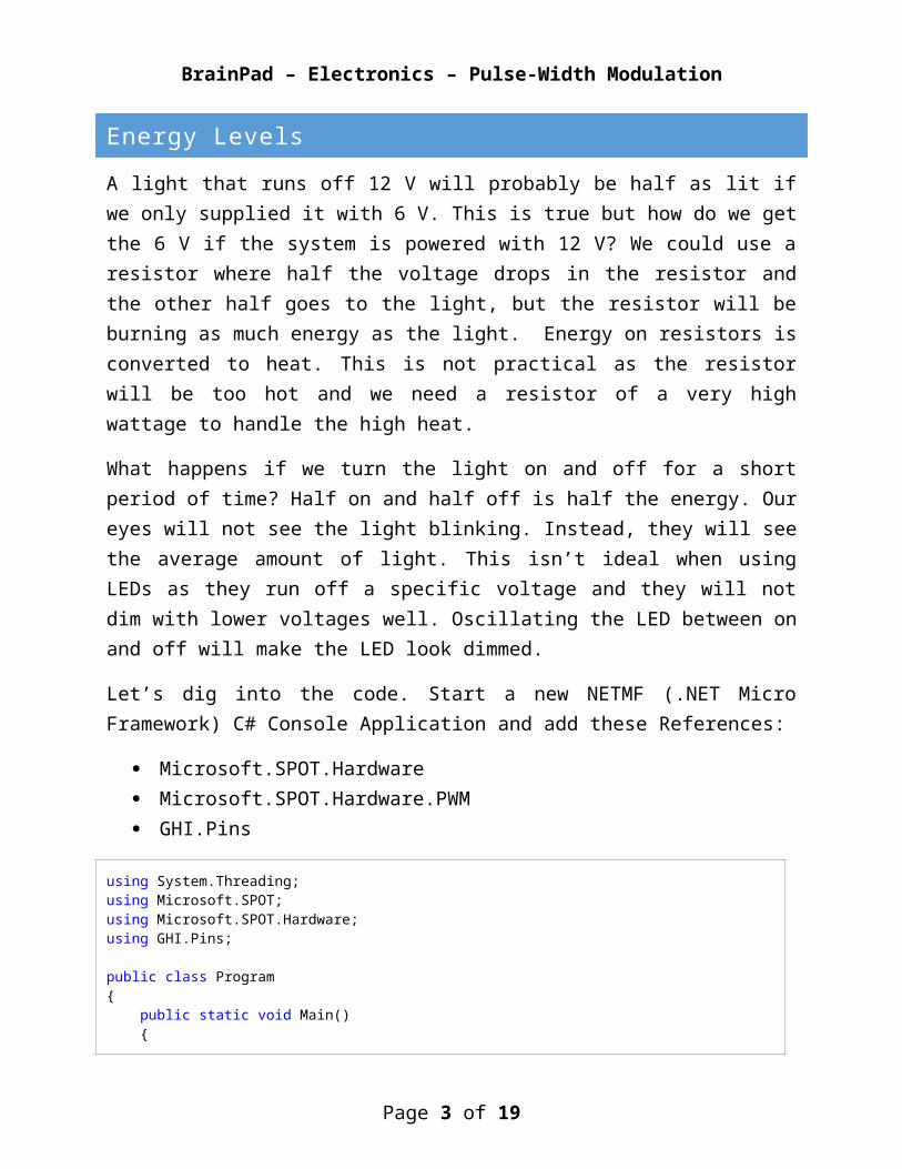
Energy Levels
A light that runs off 12 V will probably be half as lit if we only supplied it with 6 V. This is true but how do we get the 6 V if the system is powered with 12 V? We could use a resistor where half the voltage drops in the resistor and the other half goes to the light, but the resistor will be burning as much energy as the light. Energy on resistors is converted to heat. This is not practical as the resistor will be too hot and we need a resistor of a very high wattage to handle the high heat.
What happens if we turn the light on and off for a short period of time? Half on and half off is half the energy. Our eyes will not see the light blinking. Instead, they will see the average amount of light. This isn’t ideal when using LEDs as they run off a specific voltage and they will not dim with lower voltages well. Oscillating the LED between on and off will make the LED look dimmed.
Let’s dig into the code. Start a new NETMF (.NET Micro Framework) C# Console Application and add these References:
Microsoft.SPOT.Hardware Microsoft.SPOT.Hardware.PWM GHI.Pins
using System.Threading;using Microsoft.SPOT;using Microsoft.SPOT.Hardware;using GHI.Pins;
public class Program{ public static void Main() { PWM dimmer = new PWM((Cpu.PWMChannel)4, 1000, 0.5, false); dimmer.Start(); }}
Example 1 – This code constructs a PWM object on PWM channel 4.
The first argument in constructing the PWM object is the PWM channel on the processor. Looking at the schematic we see that the red LED is connected to pin PA1 (Figure 1), which is also PWM4. In the Example 1 above, we use (Cpu.PWMChannel)4 which translates to PWM channel 4 or PWM4.
Page 3 of 17

BrainPad – Electronics – Pulse-Width Modulation
Figure 1 – Here we see PA1 is connected to the red LED.
To make things easier, we’ve provided two classes within the BrainPad object. The BrainPad.Expansion and BrainPad.Peripherals objects. To add get access to these objects, in the Solution Explorer Window right-click BrainPad_Project, select Add > Existing Item… and locate the BrainPad.cs file and click Add.
The BrainPad.Expansion object can be used to easily access the labeled pins (E1 through E16) on the expansion headers. The BrainPad.Peripherals object also makes identifying pins related to such things as the traffic light faster. These both help reduce the need to look at the schematic. For example, we could access the traffic light’s red LED pin based on the schematic using G30.PwmOutput.PA1 or we could use BrainPad.Peripherals.TrafficLight.Red
which is more descriptive and easier to remember.
Going forward all examples will use the BrainPad.Expansion and BrainPad.Peripherals objects when referring to pins.
Page 4 of 17

BrainPad – Electronics – Pulse-Width Modulation
The second argument is the frequency. It’s how many times per second the signal will turn on and off. Setting this low will cause the LED to flicker because our eyes will start seeing it. We’ll go with 1,000 Hz (hertz), so the LED will turn on and off 1,000 times per second.
The third argument is the duty cycle; the ratio of on to off. Using 0.5 will result in the signal being on 50% the time. Different values and their effects are shown in Figure 2.
Figure 2 – Here we see an LED’s duty cycle set at 0.1 (10%), 0.5 (50%) and 1 (100%).
Page 5 of 17

BrainPad – Electronics – Pulse-Width Modulation
The fourth argument in the constructor is to invert the PWM signal. This is rarely used so we will always set it to false.
using System.Threading;using Microsoft.SPOT;using Microsoft.SPOT.Hardware;
public class Program{ public static void Main() { PWM dimmer = new PWM(BrainPad.Peripherals.TrafficLight.Red, 1000, 0.5, false); dimmer.Start();
double duty = 0.0; double dutyStep = 0.05;
while (true) { dimmer.DutyCycle = duty;
duty += dutyStep; if (duty < 0.05 || duty > 0.95) dutyStep *= -1;
Thread.Sleep(50); } }}
Example 2 – This code makes the red traffic light LED fade in and out.
Example 4 uses a trick to make an up and down counter. It increments the duty by a duty step but then the step is inverted to a negative number to make the counter count back down. The end result is an LED that repeatedly fades in and out.
Page 6 of 17

BrainPad – Electronics – Pulse-Width Modulation
DC Motor Speed Control
DC Motor speed can be controlled the same way LEDs and lights are controlled. The only difference is that the motor will be sensitive to the frequency used. A value around 10,000 Hz should work for most small hobby DC motors. The second problem is that motors require more current than a pin on the microcontroller can provide. This is solved by using a transistor. Motors also generate noise and reverse voltage spikes so adding a diode and a capacitor is required as shown in Figure 3.
Figure 3 – Adding a diode and a capacitor in parallel helps eliminate noise and reverse feedback. Reverse feedback occurs when the motor turns generating a current that flows in the opposite direction that can damage components. At a minimum, a diode should be used.
Page 7 of 17

BrainPad – Electronics – Pulse-Width Modulation
The BrainPad includes the required circuitry to connect a small 5 V DC motor. The header labeled DC motor can be used. This connection can also be used to wire in light bulbs that require higher currents as well.
A good example of controlling a motor is to have it run at a low speed for a few seconds and then at a high speed for a few seconds as shown in Example 5.
using System.Threading;using Microsoft.SPOT;using Microsoft.SPOT.Hardware;
public class Program{ public static void Main() { PWM dcMotor = new PWM(BrainPad.Peripherals.DcMotor, 1000, 0.5, false); dcMotor.Start();
while (true) { dcMotor.DutyCycle = 0.10; Thread.Sleep(5000);
dcMotor.DutyCycle = 1.0; Thread.Sleep(5000); } }}
Example 3 – This code loops through having a DC motor spin from slow (10% duty cycle) to fast (100% duty cycle).
Exercise
Fade two LEDs in and out but keep them in reverse order. When one is completely on, the other will very dim.
Page 8 of 17

BrainPad – Electronics – Pulse-Width Modulation
Sounds
Sounds are simply vibrations moving through air. A speaker is a device that uses an electronic signal to generate sounds. There is small speaker on the BrainPad (Figure 4), which is named buzzer.
Figure 4 – Here we see the buzzer on the BrainPad schematic.
Page 9 of 17

BrainPad – Electronics – Pulse-Width Modulation
The buzzer is connected to PB8 (PWM13) through a transistor. The commonly stated range of human hearing is 20 Hz to 20 kHz (kilohertz). A good frequency to use is 3 kHz as shown in Example 6.
using System.Threading;using Microsoft.SPOT.Hardware;
public class Program{ public static void Main() { PWM dimmer = new PWM(BrainPad.Peripherals.Buzzer, 3000, 0.5, false); dimmer.Start(); Thread.Sleep(3000); dimmer.Stop(); }}
Example 4 – This code plays the buzzer at 3 kHz for three seconds.
Note: The duty cycle should be set to 0.5 when generating sounds.
Page 10 of 17

BrainPad – Electronics – Pulse-Width Modulation
Melodies
Simple melodies can be played by programming frequencies as shown in Example 7.
using System;using System.Threading;using Microsoft.SPOT;using Microsoft.SPOT.Hardware;
public class Program{ const int NoteC = 261; const int NoteD = 294; const int NoteE = 330; const int NoteF = 349; const int NoteG = 392;
const int Whole = 1000; const int Half = Whole / 2; const int QuarterDot = Whole / 3; const int Quarter = Whole / 4; const int Eighth = Whole / 8;
public static void Main() { int[] note = { NoteE, NoteE, NoteF, NoteG, NoteG, NoteF, NoteE, NoteD, NoteC, NoteC, NoteD, NoteE, NoteE, NoteD, NoteD, NoteE, NoteE, NoteF, NoteG, NoteG, NoteF, NoteE, NoteD, NoteC, NoteC, NoteD, NoteE, NoteD, NoteC, NoteC };
int[] duration = { Quarter, Quarter, Quarter, Quarter, Quarter, Quarter, Quarter, Quarter, Quarter, Quarter, Quarter, Quarter, QuarterDot, Eighth, Half, Quarter, Quarter, Quarter, Quarter, Quarter, Quarter, Quarter, Quarter, Quarter, Quarter, Quarter, Quarter, QuarterDot, Eighth, Whole };
PWM buzzer = new PWM(BrainPad.Peripherals.Buzzer, 261, 0.5, false);
while (true) { for (int i = 0; i < note.Length; i++) { buzzer.Stop(); buzzer.Frequency = note[i]; buzzer.Start(); Thread.Sleep(duration[i]); }
Thread.Sleep(100); } }}
Page 11 of 17

BrainPad – Electronics – Pulse-Width Modulation
Example 5 – This code plays a melody by generating frequencies for specified durations.
Example 7 uses two arrays, one that holds the note and the other the duration. This is can be improved greatly by using a structure or a class that holds both in one object.
Exercise
Create a loop that increases the frequency 100 Hz each iteration. When the frequency goes over 8,000 Hz, have it go back to 50 Hz.
Page 12 of 17

BrainPad – Electronics – Pulse-Width Modulation
Servo Motors
Servo motors are used to move a mechanical arm to a specific degree between 0° to 180°. These can be used to angle a distance sensor to check the distance in different directions. They can be used to turn the steering on a small robotic vehicles. There are also full rotation servos but those are not the common use of servos.
Servo motors are controlled by a pulse that comes in 50 times a second or every 20 ms (milliseconds). The pulse width can be anywhere from 1.25 ms to 1.75 ms (Figure 5). Sending a 1.25 ms pulse will move the servo to the 0° position. Sending a 1.75 ms pulse will move the servo to move to the 180° position. Sending a 1.50 ms pulse will put the servo in the middle, at 90° position.
Figure 5 – Here we see the different pulses that move servos to a specified angle.
Page 13 of 17

BrainPad – Electronics – Pulse-Width Modulation
PWM gives us the option of providing the exact timing. While this is possible, it’s not accurate as shown in Example 8.
using Microsoft.SPOT.Hardware;using GHI.Pins;
public class Program{ public static void Main() { PWM servo = new PWM(BrainPad.Peripherals.ServoMotor, 20000, 1500, PWM.ScaleFactor.Microseconds, false); servo.Start(); }}
Example 6 – Here we set the period to 20,000 and the duration (pulse) to 1,500. This 1.50 ms pulse every 20 ms will set the servo in the 90° position.
Let’s have the servo move back and forth in Example 9.
using System.Threading;using Microsoft.SPOT.Hardware;using GHI.Pins;
public class Program{ public static void Main() { PWM servo = new PWM(BrainPad.Peripherals.ServoMotor, 20000, 1500, PWM.ScaleFactor.Microseconds, false); servo.Start();
Thread.Sleep(5000);
while (true) { servo.Duration = 1250; servo.Period = 20000; servo.Start(); Thread.Sleep(1000);
servo.Duration = 1750; servo.Period = 20000; servo.Start(); Thread.Sleep(1000); } }}
Example 7 – Let’s set the servo to 90° and wait for 5 seconds. After that we’ll move the servo from 0° to 180° and back again with a one second delay in between while looping.
Page 14 of 17

BrainPad – Electronics – Pulse-Width Modulation
Exercise
Servo motors are not very accurate. Set the servo with 1.25, 1.50 and 1.75 pulses and measure the servo position in degrees.
Page 15 of 17

BrainPad – Electronics – Pulse-Width Modulation
GHIElectronics.com/support/brainpad
Page 16 of 17