Embed Size (px)
Citation preview

Modified PVC for Potable Water & Irrigation ApplicationsAvailable in Pipe Sizes 100mm to 575mm Series 1 & 2
IMPROVED MATERIAL PERFORMANCE
HYDRAULIC EFFICIENCY
LIGHT WEIGHT
SYSTEM COMPATIBILITY
Vinidex Hydro® PVC-M

VINIDEX HYDRO® PVC-M
INTRODUCTION 1
APPLICATIONS 1
MATERIAL CHARACTERISTICS 1
BENEFITS 2
Improved Material Performance 2
Hydraulic Efficiency 2
Light Weight 2
System Compatibility 2
Product List 3
Product Data 6
Standards and Dimensions 6
DESIGN 7
System Life 7
Hydraulic 7
Structural 7
Flow Chart – Vinidex Hydro® PVC-M Pressure Pipe Series 1 – PN 6, PN 9 and PN 12
8
Flow Chart – Vinidex Hydro® PVC-M Pressure Pipe Series 2 – PN 6, PN 9, PN 12 and PN 16
8
Fatigue 10
Fatigue Design Procedure 11
Temperature 11
Installation 12
Hydro® PVC-M
INTRODUCTION
Unplasticised Poly Vinyl Chloride (PVC) has established an enviable reputation as the material of choice for infrastructure applications in both pressure and non- pressure pipelines.
With a service history dating back to the 1930’s, industry has recognised the many benefits of PVC, material stability, corrosion resistance, high strength to weight ratio, ease of handling and instal lation and excellent flow characteristics.
Development in plastics over the last 50 years has been rapid with developments in pipeline systems being at the forefront. The result is an improved PVC material, Modified Poly Vinyl Chloride or PVC-M. PVC-M is manufactured by Vinidex under the trade name Vinidex Hydro®.
Vinidex Hydro® PVC-M extends the proven benefits of PVC pipes with enhancements in fracture behaviour and hy-draulic efficiency. Vinidex Hydro PVC-M pipes are manufactured to AS/NZS 4765: Modified PVC (PVC-M) pipes for pressure applications.
APPLICATIONS
Vinidex Hydro® PVC-M is suitable for pressure applications for potable water, irrigation, fire fighting and general industrial applications in the temperature range 0 to 50° Celsius. Vinidex Hydro® is available in two diameter groups, Series 1 and Series 2, which denote the outside diameter of each group. In general the irrigation industry uses Series 1 and the potable water industry uses Series 2.
Vinidex Hydro® is available in sizes from DN 100 to 575 and pressure classes 6, 9, 12, 15, 16, 18 and 20 dependent on pipe series and diameter.
Vinidex Hydro® PVC-M
MATERIAL CHARACTERISTICS
PVC is formed by the combination of chlorine, carbon and hydrogen in the form of polymer chains. PVC-M is formed by the addition of compatible modifying agents to the PVC matrix, forming an alloy rather than a copolymer. The addition of modifying agents increases the ductility while virtually retaining the same material strength.
The modifying agents significantly improve toughness and impact properties with resistance to crack growth a key performance requirement. The change in material matrix gives greater ductile behaviour and thus ena-bles the factor of safety to be lower than PVC. Short and long term tests on Vinidex Hydro® pressure pipes have demonstrated consistently ductile behaviour, particularly in the presence of notches. The reduced factor of safety enables higher allowable stress levels, reduced wall thickness providing greater hydraulic efficiency.
Stabilisers are an integral component of PVC-M manufacture, maintaining thermal stability during the extrusion process. All Vinidex pressure pipes including Vinidex Hydro® PVC-M are manufactured using Calcium Zinc stabilisers.
AS/NZS 4765 details a broad range of material acceptance tests which guarantee achievement of ductile material characteristics.
1

Hydro® PVC-M
2
BENEFITS
Improved Material PerformanceThe alloying of PVC with modifying poly mers achieves improvement in resistance to cracking. The result is the minimisation of the effect of stress concentrators such as scratches. With a consequent reduction in the factor of safety, higher wall stresses are allowable which lead to reduced wall thickness.
Hydraulic EfficiencyThe increased internal diameter for a given external diameter makes Vinidex Hydro® a more efficient conduit than PVC and ductile iron.
Light WeightPVC is already recognised as the lightest and easiest of pipeline materials to handle. Vinidex Hydro® further increases this advantage. Depending on size and class, weight savings in excess of 10% over PVC are available.
System CompatibilityWhether supplied in Series 1 for the irrigation industry or Series 2 for the water industry, Vinidex Hydro® is fully compatible with existing pipeline systems with the full range of valves and fittings available.

Hydro® PVC-M
3
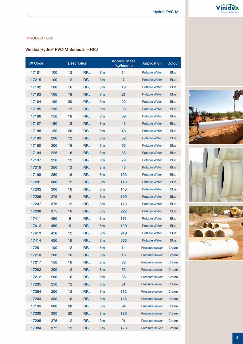
PRODUCT LIST
Vinidex Hydro® PVC-M Series 1 – RRJ
VX Code Description Approx. Mass (kg/length)
17035 100 PN9 RRJ 6m 9
17045 100 PN12 RRJ 6m 12
17080 150 PN9 RRJ 6m 19
17090 150 PN12 RRJ 6m 24
17100 200 PN6 RRJ 6m 31
17110 200 PN9 RRJ 6m 36
17120 200 PN12 RRJ 6m 47
17135 225 PN9 RRJ 6m 46
17140 225 PN12 RRJ 6m 58
17145 250 PN6 RRJ 6m 50
17150 250 PN9 RRJ 6m 56
17155 250 PN12 RRJ 6m 76
17160 300 PN6 RRJ 6m 62
17165 300 PN9 RRJ 6m 69
17170 300 PN12 RRJ 6m 96
17175 375 PN6 RRJ 6m 99
17180 375 PN9 RRJ 6m 115
17174 375 PN12 RRJ 6m 150
17171 450 PN6 RRJ 6m 155
17172 450 PN9 RRJ 6m 188
17173 450 PN12 RRJ 6m 247
17415 500 PN6 RRJ 6m 201
17416 500 PN9 RRJ 6m 236
17417 500 PN12 RRJ 6m 297
17418 575 PN6 RRJ 6m 245
17419 575 PN9 RRJ 6m 296
17420 575 PN12 RRJ 6m 388
Vinidex Hydro® PVC-M Series 1 – SCJ
VX Code Description Approx. Mass (kg/length)
17040 100 PN9 SCJ 6m 9
17050 100 PN12 SCJ 6m 19
17085 150 PN9 SCJ 6m 37
17095 150 PN12 SCJ 6m 12
17115 200 PN9 SCJ 6m 24
17125 200 PN12 SCJ 6m 49
Hydro® PVC-M
4
Vinidex Hydro® PVC-M Series 2 – RRJ
VX Code Description Approx. Mass (kg/length) Application Colour
17181 100 12 RRJ 6m 14 Potable Water Blue
17215 100 12 RRJ 3m 7 Potable Water Blue
17182 100 16 RRJ 6m 19 Potable Water Blue
17183 100 18 RRJ 6m 21 Potable Water Blue
17184 100 20 RRJ 6m 22 Potable Water Blue
17185 150 12 RRJ 6m 30 Potable Water Blue
17186 150 16 RRJ 6m 39 Potable Water Blue
17187 150 18 RRJ 6m 43 Potable Water Blue
17188 150 20 RRJ 6m 48 Potable Water Blue
17189 200 12 RRJ 6m 52 Potable Water Blue
17190 200 16 RRJ 6m 66 Potable Water Blue
17194 225 16 RRJ 6m 83 Potable Water Blue
17197 250 12 RRJ 6m 79 Potable Water Blue
17218 250 12 RRJ 3m 43 Potable Water Blue
17198 250 16 RRJ 6m 103 Potable Water Blue
17201 300 12 RRJ 6m 113 Potable Water Blue
17202 300 16 RRJ 6m 145 Potable Water Blue
17206 375 9 RRJ 6m 139 Potable Water Blue
17207 375 12 RRJ 6m 173 Potable Water Blue
17208 375 16 RRJ 6m 222 Potable Water Blue
17411 450 6 RRJ 6m 161 Potable Water Blue
17412 450 9 RRJ 6m 190 Potable Water Blue
17413 450 12 RRJ 6m 249 Potable Water Blue
17414 450 16 RRJ 6m 326 Potable Water Blue
17281 100 12 RRJ 6m 14 Pressure sewer Cream
17210 100 16 RRJ 6m 18 Pressure sewer Cream
17217 150 16 RRJ 6m 38 Pressure sewer Cream
17282 200 12 RRJ 6m 52 Pressure sewer Cream
17212 200 16 RRJ 6m 66 Pressure sewer Cream
17285 250 12 RRJ 6m 81 Pressure sewer Cream
17284 300 12 RRJ 6m 112 Pressure sewer Cream
17203 300 16 RRJ 6m 146 Pressure sewer Cream
17199 300 20 RRJ 3m 94 Pressure sewer Cream
17200 300 20 RRJ 6m 180 Pressure sewer Cream
17205 375 12 RRJ 3m 91 Pressure sewer Cream
17384 375 12 RRJ 6m 173 Pressure sewer Cream
PRODUCT LIST
Hydro® PVC-M
5
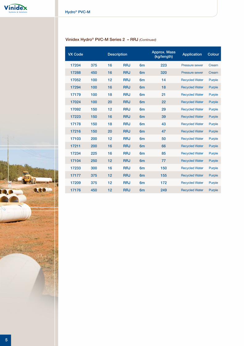
VX Code Description Approx. Mass (kg/length) Application Colour
17204 375 16 RRJ 6m 223 Pressure sewer Cream
17288 450 16 RRJ 6m 320 Pressure sewer Cream
17052 100 12 RRJ 6m 14 Recycled Water Purple
17294 100 16 RRJ 6m 18 Recycled Water Purple
17179 100 18 RRJ 6m 21 Recycled Water Purple
17024 100 20 RRJ 6m 22 Recycled Water Purple
17092 150 12 RRJ 6m 29 Recycled Water Purple
17223 150 16 RRJ 6m 39 Recycled Water Purple
17178 150 18 RRJ 6m 43 Recycled Water Purple
17216 150 20 RRJ 6m 47 Recycled Water Purple
17103 200 12 RRJ 6m 50 Recycled Water Purple
17211 200 16 RRJ 6m 66 Recycled Water Purple
17234 225 16 RRJ 6m 85 Recycled Water Purple
17104 250 12 RRJ 6m 77 Recycled Water Purple
17233 300 16 RRJ 6m 150 Recycled Water Purple
17177 375 12 RRJ 6m 155 Recycled Water Purple
17209 375 12 RRJ 6m 172 Recycled Water Purple
17176 450 12 RRJ 6m 249 Recycled Water Purple
Vinidex Hydro® PVC-M Series 2 – RRJ (Continued)

Hydro® PVC-M
6
TABLE 2 – Dimensions for Vinidex Hydro® PVC-M Pipes Series 2
Normal
Size DN
Outside Diameter
Mean OD
PN6
(mm)
PN9
(mm)
PN12
(mm)
PN16
(mm)
PN18
(mm)
PN20
(mm)Dm
min
Dn
maxT
meanID
T mean
IDT
meanID
T mean
IDT
meanID
T mean
ID
100 121.7 122.1 - - - - 4.7 112.5 6.1 109.7 6.7 108.6 7.3 107.2
150 177.1 177.6 - - - - 6.6 164.2 8.7 160.1 9.6 158.2 10.6 156.2
200 231.9 232.6 - - - - 8.6 215.2 11.3 209.8 12.5 207.3 13.7 204.8
225 258.9 259.6 - - - - 9.5 240.3 12.6 234.2 13.9 231.5 15.3 228.6
250 285.8 286.6 - - - - 10.5 265.2 13.7 258.8 15.3 255.6 16.9 252.4
300 344.9 345.8 - - - - 12.7 320.1 16.5 312.4 18.4 308.5 20.3 304.7
375 425.7 426.7 10.1 406.1 11.8 402.6 15.6 395.1 19.9 386.4 22.7 380.9 25.0 376.2
450 506.5 507.5 11.9 483.2 14.0 479.1 18.4 470.3 24.2 458.7 26.9 453.2 29.7 447.6
PRODUCT DATA
Standards and DimensionsVinidex Hydro® pipes are manufactured in accordance with AS/NZS 4765 with Standards Mark numbers 2560, 2561, 2562 and 2563.
AS/NZS 4765:2007 provides two manu facturing series relating to the outside diameter of the pipe. Series 1 is ISO compatible outside diameters (mostly metric) and Series 2
is ductile iron compatible outside diameters.
Refer to Table 1 and 2 for dimensional data.In general, the irrigation industry uses Series 1 and the potable water industry uses Series 2. Vinidex Hydro® is available in both Series 1 and 2 to suit these industries.
TABLE 1 – Dimensions for Vinidex Hydro® PVC-M Pipes Series 1
Normal Size DN
Outside Diameter Mean OD
PN6 (mm)
PN9 (mm)
PN12 (mm)
Dm min Dn max Tmean ID Tmean ID Tmean ID
100 114.1 114.5 – – 3.4 107.5 4.4 105.6
125 140.0 140.4 – – 4.2 131.9 5.4 129.5
150 160.0 160.5 – – 4.7 150.9 6.0 148.4
200 225.0 225.6 5.5 214.4 6.4 212.5 8.4 208.6
225 250.0 250.7 6.1 238.2 7.1 236.3 9.2 232.0
250 280.0 280.8 6.7 267.0 7.9 264.6 10.3 259.9
300 315.0 315.9 7.5 300.5 8.8 298.0 11.6 292.4
375 400.0 401.0 9.5 381.5 11.2 378.2 14.6 371.4
450 500.0 501.0 11.8 476.9 13.8 472.9 18.1 464.4
500 560.0 561.0 13.2 534.2 15.5 529.6 20.3 520.0
575 630.0 631.0 14.7 601.1 17.3 596.0 22.8 585.0

Hydro® PVC-M
DESIGN
System LifeIt is a common misconception that plastics pipes have a design life of 50 years, arising from the use of regression curves and adoption of the 50 year point for classification purposes.
In relation to hydrostatic stress analysis and pipe life, AS/NZS 4765 states the following: “The analysis adopts the 50 years extrapolation point on the regression curve as the reference for design purposes. This is consistent with long standing international practice.
It should not be taken that either –(a) the pipes weaken with time; or(b) the predicted life is 50 years
Actual system life is dependent on manufacture, transport, handling, installation, operation, protection from third party damage and other external factors. For water supply applications, the actual life can logically be expected to be well in excess of 100 years before major rehabilitation is required.”
HydraulicThe principles of closed conduit flow and behaviour of fluids is well established. Vinidex recommend the use of the Colebrook-White formula for the analysis of flow parameters for Vinidex Hydro® pipe. A roughness coefficient k = 0.003mm is recommended and all computations are based on water at 20° C.
Additional background information on hydraulic design can be found in the Vinidex Water Supply Manual for PVC Pipe Systems. Computational assistance is available in the Vinidex program “Fluff”, which can provide an analysis of a wide range of pipeline materials. Flow Charts for Vinidex Hydro® Series 1 and Series 2 are shown on pages 7 and 8.
StructuralUnder general pressure pipe installation conditions, including under roads, detailed calculations predicting pipe performance are not necessary. Following an extensive study of installed pipe performance, a joint project conducted by the European Plastic Pipe and Fitting Association (TEPPFA) and independent experts concluded that final deflection of pipes was controlled by the settlement of the soil after installation.
Where installation was controlled, or self-compacting granular material was used, pipe deflections were consistently low regardless of installation depth and traffic or other loads.
For unusual conditions, or depths greater than 6 metres, design calculations may be performed in accordance with AS/NZS 2566.1. The structural design aspects of buried flexible pipes to be considered are vertical deflection, ring bending strain and buckling.
Differential pressure conditions between the inside and outside of a pipe can cause a pipe to buckle inwards leading to collapse. Such conditions can arise from high external loading or negative internal pressure transients as a consequence of pipeline operating conditions. A pipes resistance to buckling is directly proportional to ring bending stiffness.
As PVC-M pipes have reduced wall thickness compared to PVC of the same PN rating, the ring bending stiffness is significantly reduced. Consequently the resistance to buckling of PVC-M is also significantly reduced. Designers should be aware of pipeline operating criteria and consult appropriate design material including AS/NZS 2566.1 to ensure the suitability of PVC-M in such applications.
For buried pipes the soil surround provides additional support against buckling providing the minimum cover height exceeds 500mm. Such support can only be realised where the embedment is properly placed and compacted with no voids around the pipe and the embedment cannot subsequently be removed or leached away.
In general where sustained negative pressures or full vacuum conditions are likely to occur, e.g. suction lines, Vinidex recommends that PN 12 pipe or higher be selected based on an appropriate factor of safety against buckling.
7

Hydro® PVC-M
8
DESIGN
Head Loss – Metres Head of Water per 100 metres of Pipe
Dis
char
ge
– Li
tres
per
Sec
ond (
L/s)
FLOW CHART – Vinidex Hydro® PVC-M Pressure Pipe Series 1 PN6, PN9 and PN12

Hydro® PVC-M
9
DESIGN
Head Loss – Metres Head of Water per 100 metres of Pipe
Dis
char
ge
– Li
tres
per
Sec
ond (
L/s)
FLOW CHART – Vinidex Hydro® PVC-M Pressure Pipe Series 2 PN6, PN9, PN12 and PN16

Hydro® PVC-M
10
DESIGN
FatigueMaterials subject to repetitive or cyclic loads can fail at lower stress levels than materials subject to constant load. This is known as fatigue failure. For thermoplastics pipe materials, fatigue only becomes a design parameter when very high numbers of cycles are applied.
The behaviour of thermoplastic materials in cyclic operation conditions has been extensively studied. Vinidex has developed an appropriate design procedure for such applications.
The two design parameters are the magnitude of the pressure range and the frequency of the application, leading to the calculation of the number of cycles applied over the design life of the pipeline. In cases where lifetime cycles exceed 26,000, a higher class of the pipe may be required than indicated by the static or maximum pressure.
Extensive studies into the fatigue behaviour of thermoplastics have been used to establish a relationship between pressure range, defined as the difference between maximum and minimum pressure (see Figure 1) and the number of cycles to failure.
This relationship yields a load factor which is applied to the operating pressure to enable the selection of the appropriate class of pipe.
The approach adopted by Vinidex is conservative recognising that the experimental data demonstrates a degree of scatter. This ensures an appropriate factor of safety given potential changes in the pipeline operating conditions over the life of the pipe and other operational conditions such as installation and maintenance standards.
For simplicity, the pressure range is defined as the maximum pressure minus the minimum pressure including all transients experienced by the system during normal operations as per Figure 1. The effect of accidental conditions such as power failure may be excluded. Figure 1 illustrates the definition of a cycle as a repetitive event. In some cases the cycle pattern may be complex and it may be necessary to consider the contribution of secondary cycles.
The Maximum Cyclic Pressure Range (MCPR) for a pipe can be calculated using the Fatigue Cycle Factors in Table 3:
MCPR = PN/10 x f
This should not exceed the predicted pressure range in the pipeline.
Alternatively, follow the procedure and use the design graph in Figure 2 to select the correct class of pipe.
One cycle
Time
Line
Pres
sure
Pres
sure
Ran
ge
FIGURE 1 – Pressure Cycle

Hydro® PVC-M
11
DESIGN
Fatigue Design ProcedureTo select the appropriate pipe class for fatigue loading, the following procedure should be adopted:
1. Estimate the likely pressure range, ∆P i.e. the maximum pressure minus the minimum pressure.
2. Estimate the frequency or the number of cycles per day, which are expected to occur.
3. Determine the required service life and calculate the total number of cycles which will occur in the pipe lifetime.
4. Using Figure 2, draw a vertical line up from the x-axis at delta P and a horizontal line from the y-axis at the total number of cycles in the pipe lifetime.
5. Find the intersection point between the horizontal and vertical lines.
6. Select the pipe class that bounds the region of this intersection point as the minimum required for these fatigue conditions.
TABLE 4 – Temperature Rating of Vinidex Hydro® PVC-M Pipes Maximum Allowable Pressure (MPa).
Temperature °C≤ 25 30 35 40 45 50
PN6 0.60 0.52 0.47 0.42 0.38 0.35
PN9 0.90 0.78 0.71 0.63 0.54 0.46
PN12 1.20 1.04 0.95 0.84 0.77 0.70
PN16 1.60 1.44 1.26 1.12 1.02 0.93
PN18 1.80 1.57 1.42 1.26 1.15 1.04
PN20 2.00 1.74 1.58 1.40 1.28 1.16
FIGURE 2 – Fatigue Design Chart for PVC-M Pipes
TABLE 3 – Fatigue Load Factors by number of Cycles
Total cycles Approx No. cycles/day for 100 year life
PVC-M Fatigue Load Factors
26,400 1 1.00
100,000 3 0.67
500,000 14 0.41
1,000,000 27 0.33
2,500,000 82 0.25
5,000,000 137 0.25
10,000,000 274 0.25
1 000 000
10,000,000
pe li
fetim
e
Selection of PVC-M pipe pressure class fatigue applications
10,000
100,000
1,000,000
0.10 0.20 0.30 0.40 0.50 0.60 0.70 0.80 0.90 1.00 1.10 1.20 1.30 1.40 1.50 1.60 1.70 1.80 1.90 2.00
Tota
l Num
ber o
f Cyc
les
in p
i
Maximum cyclic pressure range MCPR (MPa)
TemperatureThe nominal working pressure rating of Vinidex Hydro® pipes is determined at 20°C. However, Vinidex Hydro® pipes are suitable for use at temperatures up to 50°C. Where the service temperature exceeds 20°C, use Table 4 to determine appropriate pipe class.
Hydro® PVC-M
12
INSTALLATION
Vinidex recommend that Vinidex Hydro® PVC-M pipes are constructed in accordance with AS 2032 – Installation of PVC pipe systems and Vinidex recommendations.
Installation techniques for Vinidex Hydro® pipes are similar to those used for standard PVC pipes and the same degree of care and caution must be exercised.
Quality non-cohesive material should be used for pipe bedding, side support and overlay. In general 1° deflection for rubber ring joints, is available at each socket-spigot joint. The pipe side support material should be placed evenly on both sides of the pipeline to two thirds the height of the pipe diameter and compacted by hand tamping.
Side fill material should be worked under the sides of the pipe to eliminate all voids and provide maximum pipe haunching.
The pipe overlay material should be levelled and compacted in layers to a minimum height of 150mm above the crown of the pipe or as specified.
For above ground installations the support spacings recommended in AS 2032 can also be used for Vinidex Hydro® pipes. These support spacing result in negligible deflection in PVC pipes full of water.
The field testing procedures specified in AS2032 and Vinidex recommendations.
AUSTRALIAN OPERATIONS
Sydney 254 Woodpark Rd Smithfield NSW 2164 Wagga Wagga280 Byrnes Rd Wagga Wagga NSW 2650 MelbourneUnit 1, 10 Duerdin St Notting Hill VIC 3168
231-245 St Albans Rd Sunshine VIC 3020
Adelaide9–11 Kaurna Ave Edinburgh SA 5111
Launceston15 Thistle St Sth Launceston TAS 7249
Brisbane224 Musgrave Rd Coopers Plains QLD 4108
Townsville18 Enterprise St Bohle QLD 4818
ToowoombaLot 2 Witmack Rd Wellcamp QLD 4350 Rodney Industries 19 Valente Close Chermside QLD 4032
Darwin61 Marjorie St Pinelands NT 0829
PerthSainsbury Rd O’Connor WA 6163
Vinidex Pty Limited ABN 42 000 664 942
HEAD OFFICE
Level 4, 26 College Street Darlinghurst NSW 2010 PO Box 747, Darlinghurst NSW 1300
Reception: +61 2 8278 0500
CUSTOMER SERVICE
Phone: 13 11 69 Fax: 13 24 43
Email: [email protected] Web: www.vinidex.com.au
Limitation of Liability
This product catalogue has been compiled by Vinidex Pty Limited (“the Company”) to promote better understanding of the technical aspects of the Company’s products to assist users in obtaining from them the best possible performance. The product catalogue is supplied subject to acknowledgement of the following conditions:1. The product catalogue is protected by copyright and may not be cop-ied or reproduced in any form or by any means in whole or in part without prior consent in writing by the Company. 2. Product specifications, usage data and advisory information may change from time to time with advances in research and field experience. The Company reserves the right to make such changes at any time without further notice. 3. Correct usage of the Company’s products involves engineering judgements, which can not be properly made without full knowledge of all the conditions pertaining to each specific installation. The Company expressly disclaims all and any liability to any person whether supplied with this publication or not in respect of anything and all of the consequences of anything done or omitted to be done by any such person in reliance whether whole or part of the contents of this publication. 4. No offer to trade, nor any conditions of trading, are expressed or implied by the issue of content of this product catalogue. Nothing herein shall override the Company’s Condition of Sale, which may be obtained from the Registered Office or any Sales Office of the Company. 5. This product catalogue is and shall remain the property of the Company, and shall be surren-dered on demand to the Company. 6. Information supplied in this product catalogue does not override a job specification, where such conflict arises; consult the authority supervising the job. © Copyright Vinidex Pty Limited.
VIN 186-20180712