Embed Size (px)
Citation preview

Vinnova research report2010-00308
Radon charcoal cleaner


Sida 1 (56)
Radon charcoal cleaner
Ve
rkty
g:
Rad
on-P
M /
V-A
2 /
20
10
-01
-12
Doku
me
nt:
K:\
PR
OJE
KT
\53
693
Vin
no
va
\Rapp
ort
\Fin
al re
po
rt\P
DF
\Le
v\B
jerk
ing
- R
ese
arc
h r
ep
ort
pu
b.d
ocx
Sp
ata
t: 2
01
2-0
3-1
6
Name of project
Radon charcoal cleaner
VINNOVA
101 58 Stockholm
Sverige
Date
2010-11-30
Project leader:
Connie Boox, Bjerking AB, Box 1351, SE-751 43 Uppsala, Sweden
Project members:
Mimmi Andersson, Bjerking AB Ivan Štekl, Fadahat Mamedov, Karel Smolek, IEAP CTU in Prague, Horska 3a/22, 12800 Prague 2, Czech Republic Karel Jílek, Jiří Hůlka, Aleš Froňka, Josef Thomas, NRPI, Prague, Czech Republic Martin Jiránek, Faculty of Civil Engineering, CTU in Prague, Thakurova 7, Prague 6, Czech Republic Sture Petersson, MidDec Scandinavia AB, Akroken, Sundsvall, SE-851 70, Sweden

Sida 2 (56)
Bjerking AB
Summary
Radon is the second biggest cause of lung cancer after smoking and scientific evidence suggests that 3-14 % of lung cancers are caused by exposure to indoor radon. There are three different sources which can cause high radon levels in a house; soil and rock under and around the house, the construction material and household water. There are several mitigation methods for radon suppression, which are described in this report, that are being used today. Choice of mitigation method is depending on source of radon and other circumstances in different houses.
This research project was undertaken NRPI Czech Republic, IEAP CTU in Prague, MidDec Scandinavia AB, Sweden and Bjerking AB, Sweden. The aim of the project is to develop and verify a new technology for radon mitigation in buildings with elevated concentrations of radon, in order to obtain another tool for radon mitigation.
There are several ways of remediating radon, especially when radon from the ground is the source.
Reducing radon concentration in houses where the construction material is the source can be more
difficult and costly. Therefore it is suggested to concentrate on the charcoal trap for houses with
radon mainly from the construction material as an alternative to installing a mechanical ventilation
system.
The aim of initial experiments performed in NRPI was to propose and verify an appropriate model
describing indoor air radon behaviour under active charcoal filter operation which should allow us
to develop a proper prototype of charcoal air cleaner commercially applicable both in homes and in
offices, schools, hospitals, etc.
To fulfil the main goal the experiments were divided into three types in order to study i) efficiency of
two different types of charcoal (K48 and 207B 1,5KI), ii) influence of radon trap on the radon
activity in a small volume (142 litres) with zero ventilation (simplified approach); iii) influence of
radon trap and the realistic values of indoor - outdoor ventilation ranging up to approx. 0,5/h on the
radon activity in large volume (45 m3). Results from the experiments were compared with
theoretical models and it showed good comparison.
The experiments showed that the charcoal type K48 adsorbed radon better compared to charcoal
type 207B 1,5 K. It also showed that the radon suppression factor was strongly depending on the
ventilation and the charcoal trap was less efficient when the ventilation was higher.
Important technical parameters of future prototype are mass of charcoal, temperature, air flux and ventilation. Concerning radiation protection needs data from the experiments indicate that the risk of radiation is not a limiting factor but it needs to be further studied. The most crucial parameter seems to be energy consumption when cooling the charcoal to obtain high efficiency in radon reduction with a reasonable mass of charcoal that can be put in a family house.
In continuing experiments the ability for activated charcoal to adsorb not only radon but also
pollutants in the indoor air can be tested. If this proves successful it would give the charcoal trap an
advantage compared to other radon suppressing methods.
A future plan is also to integrate the charcoal bed system with a device for radon measurement,
which could automatically detect radon concentrations and control the charcoal cleaning system.

Sida 3 (56)
Bjerking AB
Table of contents
SUMMARY ............................................................................................................. 2 1 BACKGROUND .................................................................................................. 5 2 INTRODUCTION ................................................................................................ 6 3 COMPILATION OF METHODS TO SUPPRESS RADON ACTIVITY IN BUILDINGS ..................................... 7
3.1 Background ............................................................................................ 7 3.2 Radon from building materials ..................................................................... 7
3.2.1 Replacement of radioactive materials ...................................................... 7 3.2.2 Sealing of wall surfaces ....................................................................... 7 3.2.3 Increased ventilation .......................................................................... 7
3.3 Radon from the ground .............................................................................. 8 3.3.1 Sealing entry routes ............................................................................ 8 3.3.2 Radon-proof membranes ...................................................................... 8 3.3.3 Sub-slab depressurization and ventilation systems ....................................... 9 3.3.4 Soil ventilation through existing drainage piping ......................................... 9 3.3.5 Air cushion method ............................................................................. 9 3.3.6 Radon well ...................................................................................... 10
3.4 Air gap ventilation ................................................................................... 10 3.4.1 Ventilation of continuous air gaps .......................................................... 10 3.4.2 Ventilation of perimeter basement walls made of hollow blocks ..................... 10
3.5 Building ventilation ................................................................................. 10 3.5.1 Improving ventilation in living spaces ..................................................... 10 3.5.2 House pressurization .......................................................................... 10 3.5.3 Improving ventilation in cellar or crawl space ........................................... 11
3.6 Measures for crawl spaces ......................................................................... 11 3.6.1 Sealing the ground surface................................................................... 11 3.6.2 Reduction of air pressure under the plastic film ........................................ 11
3.7 Radon from water ................................................................................... 11 3.8 Other methods decreasing indoor radon concentration ...................................... 12
3.8.1 Fluid based radon mitigation system ....................................................... 12 3.9 Radon mitigation system based on charcoal beds ............................................. 12 3.10 Radon reduction systems summary (RADPAR project) ........................................ 12
3.10.1 Summary of preventive and remedial measures actually applied .................... 12 3.10.2 Installation costs of remedial and preventive measures ............................... 16 3.10.3 Operation and maintenance costs .......................................................... 17
3.11 Standardisation of radon countermeasures ..................................................... 18 4 BASIC THEORY AND DESCRIPTION OF EXPERIMENTAL SETUPS ................................................. 20
4.1 Type I experiment ................................................................................... 20 4.2 Type II experiment .................................................................................. 22 4.3 Type III experiment ................................................................................. 23 4.4 Comment on experiments .......................................................................... 23
5 THEORETICAL MODELS USED FOR EXPERIMENTAL DATA PROCESSING AND DESCRIPTION OF RADON REDUCTION
IN A NRPI CHAMBER USING THE CHARCOAL TRAP. RESULTS OF EXPERIMENTAL TESTS. ............................ 26 5.1 Data processing of Type I experiment ........................................................... 27
5.1.1 Theoretical description of radon reduction in a building (chamber) using the
charcoal trap ............................................................................................... 29 5.2 Data processing of Type II experiment........................................................... 32 5.3 Data processing of Type III experiments ......................................................... 33
6 DEFINITION OF TECHNICAL PARAMETERS OF FUTURE PROTOTYPE. ........................................... 35 6.1 Estimation of possible prototype testing at NRPI. ............................................. 35 6.2 Comment on theoretical models .................................................................. 36 6.3 Required energy for cooling charcoal ............................................................ 37
6.3.1 Comment on needed cooling device ....................................................... 38

Sida 4 (56)
Bjerking AB
7 PREDICTION OF OPERATIONAL CONDITIONS TO REACH REQUESTED RADON MITIGATION EFFICACY ........... 39 7.1 Limits of adsorption device type A ............................................................... 39 7.2 Limits of adsorption device type B ............................................................... 40 7.3 Conclusion ............................................................................................ 44
8 ESTIMATION OF RADIATION PROTECTION NEEDS. STUDY OF ROLE OF AEROSOLS. ............................ 45 8.1 Active charcoal (AC) bed as a radioactive source ............................................. 45
8.1.1 Rn 222+ .......................................................................................... 45 8.1.2 Pb 210+ .......................................................................................... 45 8.1.3 Gamma dose rate (Ḋg). ....................................................................... 45
8.2 Radioactive waste ................................................................................... 46 8.3 Role of aerosols ...................................................................................... 46
9 CONCLUSION AND FUTURE PLANS............................................................................. 49
REFERENCES ......................................................................................................... 50
APPENDIX 1. MITIGATION RATIO VS VENTILATION RATE ............................................................ 51 APPENDIX 2 ......................................................................................................... 54
Sida 5 (56)
Bjerking AB
1 Background
Radon is a naturally occurring radioactive gas produced from the radioactive decay of uranium,
which is found in rocks and soil. Radon escapes easily from the ground into the air, where it
disintegrates through short-lived decay products called radon progeny. As we breathe, radon
progeny are deposited on the cells lining the airways where the alpha particles can potentially
cause lung cancer.
Scientific evidence suggests that 3-14% of lung cancers are caused by exposure to indoor radon.
Radon is the second biggest cause of lung cancer after smoking. As many people are exposed to
low and moderate radon concentrations, the majority of lung cancers related to radon are caused
by these exposure levels rather than by higher concentrations. The WHO Handbook recommends
as reference level 100 Bq/m3. If this level cannot be reached due to country-specific conditions, the
chosen level should not exceed 300 Bq/m3 according to recommendations of WHO. WHO is now
preparing a new handbook “Handbook for radon communication with building professionals”, which
means they are now entering the field of radon mitigation.
International Atomic Energy Agency (IAEA) addresses radon as one of the main sources of
radiation exposure. IAEA require that the government shall provide information on indoor levels
and associated risks and, if appropriate, shall establish and implement an action plan for controlling
public exposure to indoor radon.
According to the European Basic Standards Directive (draft February 2010) each member state in
the EU shall establish an action plan to manage long term risk from radon exposure in dwellings,
buildings with public access and workplaces for any source of radon ingress, whether from soil,
building materials or water.
There are three different sources which can cause high radon levels in a house; soil and rock under
and around the house, the construction material and household water. The radon concentration in the
indoor air is depending on different parameters such as uranium concentrations in the soil and/or
construction material, leakage of air into the ground and ventilation system. There are several
mitigation methods for radon suppression, which are described in this report, that are being used
today. Choice of mitigation method is depending on source of radon and other circumstances in
different houses.
This research project was undertaken by National Radiation Protection Institute (NRPI) Czech
Republic, Institute of Experimental & Applied Physics, Czech Technical University, IEAP CTU in
Prague, MidDec Scandinavia AB, Sweden and Bjerking AB, Sweden.
NRPI is a governmental institution established by the State Office for Nuclear Safety. Its main role
is to provide measurements and expertise, intercomparison, radiation monitoring network data
acquisition and processing, preparation of methodologies, guidance and recommendations.
IEAP CTU is a university research institute concentrated mainly on basic research such as detector
techniques, subatomic physics, particle physics and astro physics and its applications (low
background measurements, special pixel detectors, radon research and development programme
– diffusion, emanation, measurement of radon activities).
MidDec is working on radon regulating in another Vinnova project and is also collaborating with CTU.
Bjerking AB is a consultant company which covers consultant services in the whole building process,
from architects and construction engineers to building management installation services, civil
engineering, geotechnical and environmental investigations. Bjerking AB has a very long experience
with radon mitigation in different type of buildings. Bjerking took part in the first radon investigations
made in single family houses in 1978 and has conducted numerous radon investigations, including
suggesting suitable mitigation methods, in different types of buildings throughout the years. Several
research projects have been carried out in the radon field and Bjerking is involved in educational
programmes given by Swedish Radiation safety Authority (SSM).

Sida 6 (56)
Bjerking AB
2 Introduction
The aim of the project is to develop and verify a new technology for radon mitigation in buildings
with elevated content of radon. The project was concentrated on the feasibility study of the
suppression of radon concentration in houses in Sweden and other countries, in which the level of
radon concentration is above acceptable levels.
Suppression of radon concentration could be a combination of different, e.g. shielding foils on the
ground, ventilation under the house or using radon trap in the ventilation loop based on charcoal
filtration.
The original proposal included the following items:
simple model (different scenarios) of radon suppression inside building based on radon capturing on charcoal;
definition of technical parameters of prototype (mass of charcoal, needed temperature) to decide needed size of the hole installation.
compilation of existing mitigation methods of radon suppression;
proposal of test of future prototype
estimation of radiation protection (radioactivity inside charcoal container, access to the container, waste handling);
study of roles of aerosols in air and their influence on radon behaviour.
Radon trapping which is subject of the feasibility study is based on technology used in low
background experiments located in underground laboratories (Super-Kamiokande – neutrino
oscillations, NEMO 3 – double beta decay). The complicated task of achieving reduced levels of
radon in the Super-Kamiokande experiment is well documented (Super-Kamiokande Collaboration,
Physics Letters B 452 (1999) 418. In Modane underground laboratory the Radon Trapping Facility
(RTF) was introduced in October 2004 by a team of French-Swiss-Czech scientists. The RTF takes
air from the lab which is typical active at the level 10-25 Bq/m3, purifies it to the level of 1 - 5
mBq/m3 providing a flow of air at 150 m
3/h. The RTF is based on the same principle as that used in
the Super-Kamiokande experiment modified by using cooling system. Activated charcoal is used to
slow the motion of radon relative to the other components of air (nitrogen, oxygen, argon). This
process is often referred to as trapping.
This report is divided into nine chapters starting with background and introduction in the first and
second chapter. The third chapter includes compilation of methods used in practice today to
suppress radon in houses. The fourth chapter provides detailed description of the experimental
setups used for the benchmark tests. The fifth chapter describes the theoretical approach
developed for the purpose of the project, processing of the experimental data as well as
extrapolation of the theory towards the future prototype of radon trap facility for radon suppression.
The sixth chapter defines the parameters of the first prototype proposed to be built. In the seventh
chapter predicted operational conditions for requested radon mitigation efficacy is described. The
eighth chapter describes briefly the needs of the project towards the protection against radioactivity
captured in the charcoal during long-term running. The ninth and last chapter concludes the
activities provided by the project team and proposal of future project (prototype of radon trap facility
for radon suppression).

Sida 7 (56)
Bjerking AB
3 Compilation of methods to suppress radon activity in
buildings
3.1 Background
The main source of indoor radon in most buildings is the subjacent soil gas while the building
materials in most cases make only a smaller contribution. In houses with radon problem the ground
stands for 80-95 % of the problem. The level of radon in a building is, however, to a large extent
influenced by the properties of the building itself and its usage. Critical building parameters are, for
example, coupling to the ground, leakage distribution of the building envelope, type of
heating/ventilation systems and occupant living comfort preferences.
3.2 Radon from building materials
All stone-based building materials contain uranium. The quantity of uranium in the building material
is normally low and is of no practical significance. However, in several countries some building
materials that contain uranium in higher level were used for construction of buildings in the past.
This was usually the case of light-weight concrete made from uranium-rich alum shale, fly ash,
clinker, slag or waste materials from uranium ore processing.
3.2.1 Replacement of radioactive materials
This is normally a very expensive method and therefore it is recommended in exceptional cases
only. However it can be used when a greater renovation of a building is planned. Materials that can
be replaced are:
Non-structural partitions. For example, non-structural walls.
Thermal insulation in floor structures made of crushed alum shale-based lightweight concrete, waste materials from uranium ore processing, slag, fly ash, etc.
Internal plasters made of pulverized waste materials from uranium ore processing.
3.2.2 Sealing of wall surfaces
Walls that are made of uranium rich materials can be covered with a sealing that prevents the
radon formed in the wall material from being exhaled from the wall surface to the room air. The
technique is most efficient on outer walls since the radon can exhale on the outside of the wall.
Wall coverings can be made of different materials, such as epoxy or polyurethane paints or vinyl
wallpapers usually made of two paper foils with three layers of plastic foil between. Aluminium foils
are today banned due to the risk of spreading dangerous electrical currents.
In general, this method is not so much efficient. The problem with the technique is to get a good
coverage of the entire wall including connections at windows and electrical sockets. Another
weakness of this method is a high sensitivity of the surface coating to puncturing. If the surface
coating is applied on inner surface of the external wall with low thermal resistance, it may result in
surface condensation.
3.2.3 Increased ventilation
Radon exhalation from building materials with higher content of uranium is constant over time. If
the air exchange is increased the radon concentration indoors will decrease proportionally. This is
one of the most used and most efficient mitigation techniques convenient for such situations.

Sida 8 (56)
Bjerking AB
3.3 Radon from the ground
Subsoil is the most important and commonest source of radon. Common levels of radon in the soil
air are 10 000 – 50 000 Bq/m3 but on uranium rich soil the level can be up to 200 000 Bq/m
3 or
even more. Radon is actively sucked from the subsoil through leakages in the substructure of the
building. This is due to the under-pressure in the lower parts of buildings generated by the stack
effect and wind forces. Radon can easily penetrate through a concrete structure with waterproofing
– it is transported through cracks, through leakages around service pipe entries, and through
imperfectly sealed inspection chambers.
3.3.1 Sealing entry routes
Sealing entry routes is commonly used remediation method and it is often used as an additional
method in combination with other methods. It is always advisable to seal as many leaking points as
possible in parts of the building that have contact with the ground. Common points of leaking are:
Cracks in the structure
Gaps between the basement wall and slabs
Service hatches over waste pipes
Dried out floor drains
Incoming electric power and telecommunication cable entries
Water and sewage pipe entries.
A variety of materials can conceivably be used for caulking, such as jointing compound, bitumen,
concrete with expansive agent, epoxy based compounds, etc. The caulking can also be completed
with a surface sealant.
3.3.2 Radon-proof membranes
3.3.2.1 Continuous membrane over the whole building substructure
Radon-proof membranes above or below the floor slab and over the perimeter basement walls are
commonly used in EU countries as the basic protection against radon from the soil. Membranes
must be applied continuously, i.e. over the entire surface of the building substructure that is in
contact with the soil. All joints between membranes and all pipe penetrations must be carefully
sealed. Radon-proof membranes must withstand permissible movements of the building
substructure and their durability must correspond to the expected lifetime of the building. They can
be selected from common waterproofing materials available on the building market. As the
selection tool radon diffusion coefficient of the membrane can be used. Examples of suitable
materials are: bitumen membranes, polymeric membranes such as PVC, LDPE, HDPE, PP, TPO
and EVA. Materials that are highly permeable to radon and thus cannot serve as radon barriers
are: cement coatings, polymer-cement coatings, bentonite and rubber membranes. In some
countries bitumen membranes with Al foil are prohibited for application as a radon-proof membrane
due to their very low tear resistance. Other material that is banned for radon barriers are plastic
membranes with dimples, because it is almost impossible to form airtight joints with this material.
3.3.2.2 Non-continuous membrane
In some countries the radon-proof membranes are not applied continuously, i.e. over the entire
surface of the building substructure in contact with the soil, but instead over the wall-floor joint or
over the perimeter basement walls only. The aim of this measure is to reduce radon transport
through permeable materials, joints between wall elements and cracks in basement walls.

Sida 9 (56)
Bjerking AB
3.3.3 Sub-slab depressurization and ventilation systems
The sub-slab depressurization (SSD) systems are the most efficient and used methods to reduce
the radon concentration in the indoor air. Numerous variations of these systems are known, but the
principle of their behaviour is always the same. Radon-laden air from the soil under the house is
extracted to the outdoor air. As a result of the soil ventilation radon concentration under the house
decreases due to dilution and a slight underpressure is generated under the house. The air
pressure must be lowered under the whole building to get a good reduction of radon levels. These
two effects reduce radon transport from the soil into the house. If a fan is used to draw air from the
sub-slab soil, the system is called active SSD. Nevertheless, SSD system can also be passive. In
passive SSD, the vent pipe is led to the open air on the roof without a fan. It should be noted that
the efficiency of the passive SSD is lower than that of the active SSD.
3.3.3.1 Radon sump
Radon sump is a basic type of SSD systems. Radon sump is essentially a hole excavated under
the slab through the slab or through the perimeter foundation. The soil air from the sump is drawn
out to the outside air by a plastic pipe on which a fan can be installed. Radon sump is used as a
remedial as well as a preventive measure.
3.3.3.2 Drilled tubes
In this case the soil air is extracted by means of perforated tubes drilled into the sub-floor region
through the basement wall from the cellar, through the perimeter foundation from the trench
excavated in the ground outside the house or from the internal floor pit. The length of the
perforated tubes can be up to 6 m and thus they ensure better pressure distribution within the sub-
slab soil than sumps, because their effective suction area is greater. This system is a Czech
invention and was primarily designed for the remediation of existing buildings, however its
application in new buildings becomes more and more common.
3.3.3.3 Network of perforated pipes
The system consists of the network of perforated (usually flexible) pipes that are inserted into the
layer of coarse gravel placed under the slab. This method is suitable as a preventive measure for
new buildings, however it can be applied also as a remedial measure in existing buildings, if
reconstruction of floors is planned.
Systems according to 3.3.1, 3.3.2 and 3.3.3 can be installed in new buildings as a preparatory
form. Preparatory form means that a radon sump, tubes or pipes are installed beneath the floor
slab during the construction of the house. They can be later taken into use and activated if the
indoor radon concentration in a completed house exceeds the reference level. The exhaust duct of
these systems can be sealed inside or outside the house or it can be led through the house onto
the roof to open air.
3.3.4 Soil ventilation through existing drainage piping
In this method the soil air is drawn from the ground through existing drainage piping that is located
outside the footings of the house and has the form of a partial or continuous loop around the
house. In proper conditions, negative pressure field and soil ventilation is obtained in large area
covering also the area beneath the house. Best results are obtained when the drainage piping is
located below the lowest level of the footings. This method is used rarely and only for remediation
of existing buildings.
3.3.5 Air cushion method
As suggested by its name, the method is based on pumping air from the building to the sub-floor
region in order to increase the air pressure in the ground under the house. This pushes away some
of the radon containing air beneath the slab. Radon concentration under the house decreases due
to dilution. This method is used rarely and only for remediation of existing buildings.

Sida 10 (56)
Bjerking AB
3.3.6 Radon well
The radon well is a Swedish invention and is intended for use in thick layers of soil with high air
permeability, such as gravel and coarse sand, primary eskers. A radon well lowers the air pressure
in large volume of soil, and the entire system can therefore be located outside the building. The
radon well can be made in different sizes and can serve developments ranging from a one family
house to a group of houses. The effect of the well extends up to 50-60 m and in some cases even
longer, from the well.
The radon well is located entirely underground and can be covered with gravel or a lawn, if
required. On cultural buildings such as churches and castles with radon problems, the radon well
often is a usable solution, since there is no need for interference inside the buildings.
3.4 Air gap ventilation
3.4.1 Ventilation of continuous air gaps
A continuous air gap can be a part of floor structures resting on the soil or perimeter basement
walls. Plastic membranes with dimples can form the air gap. The height of the gap is usually 10-20
mm. The air gap is connected usually by a vertical exhaust pipe to a roof fan or rotating cowl that
draws air from the gap. Since the vertical exhaust pipe runs through the heated part of the house, it
can be also used as a passive system creating a slight under-pressure in the gap without a fan.
This system is used as a remedial as well as a preventive measure.
3.4.2 Ventilation of perimeter basement walls made of hollow blocks
This system is intended for use in houses with perimeter basement walls made of hollow concrete
blocks through which radon penetrates from the soil into the indoor environment. Radon can be
drawn from the air spaces within the basement walls before it can enter the house („wall suction‟) or
the indoor air can be blown into the walls so that radon is prevented from entering the walls („wall
pressurization‟). Application of this method is not common.
3.5 Building ventilation
3.5.1 Improving ventilation in living spaces
Improving ventilation in living spaces may include various measures. Sometimes only opening or
adding the fresh air vents is adequate for lowering the radon levels by increasing the ventilation
rate. In general, the energy consumption is proportional to the ventilation rate. Hence, by
increasing the air exchange the energy consumption is also increased. However, if the initial air
exchange rate is low, which is often the condition for the efficiency of the method, the ventilation
rate should be increased to ensure the quality of the indoor air. The ventilation rate of 0.5 air
exchange per hour (ACH) is a typical recommendation in many countries.
Installation of a new mechanical supply and exhaust ventilation with heat recovery system
decreases the energy consumption compared to other ventilation schemes. A heat recovery
system uses heat in the exhaust air to warm the incoming air. In an air-conditioned house, in warm
weather, the process is reversed: the exhaust air is used to cool the incoming air. This saves
between 50 and 80% of the warmth/coolness that would be lost in an equivalent ventilation system
without a heat exchanger.
3.5.2 House pressurization
The principle of this remediation method is to create a slight overpressure within the dwelling
compared to the sub-slab soil using a ventilation unit with a fan. The overpressure eliminates the
indoor underpressure, which decreases the radon supply rate from the soil into the house. At the
same time, the air exchange rate increases and thus radon concentration decreases also by
dilution. To ensure efficiency of this system, the building must be relatively airtight.
Sida 11 (56)
Bjerking AB
In some countries house pressurization is not allowed or not recommended due to risk of moisture
problems. This kind of problems may arise in cold climates when warm indoor air encounters cold
structures in the house envelope that may result in condensation of water.
3.5.3 Improving ventilation in cellar or crawl space
Improving ventilation in cellar or in crawl space are commonly used remediation methods. The
ventilation may be improved either with or without a fan. The simplest way to increase ventilation in
the cellar or crawl space is to provide more air valves in the perimeter basement or foundation
walls. In other cases it is necessary to improve the ventilation by using a fan. The efficiencies of
both methods are about 50 %.
3.6 Measures for crawl spaces
Buildings on foundations with crawl space can be dealt with in the same manner as buildings with
basement or buildings built on concrete foundation slabs. But the crawl space also allows other
remedial techniques to be used provided that the height is big enough to allow access.
3.6.1 Sealing the ground surface
In modern buildings the ground in the crawl space normally is covered with a plastic film which
serves as a barrier against the diffusion of moisture from the ground. The film is usually covered
with a sand layer to hold it in place. If the film is in good condition and covers the entire ground
surface it will provide a good protection against radon from the ground.
In older houses there is no plastic film and there it is possible to cover the ground surface with a
plastic film. In this case it is important to get a good connection between the plastic film and the
foundation wall to prevent radon from leaking up at the connection. Other possible solution is to
perform a concrete slab as a gas seal. Sometimes it is also necessary to seal the foundation wall to
stop radon from leaking up to the living space thru cracks or structures in the wall.
3.6.2 Reduction of air pressure under the plastic film
If the accessibility of the crawl space is such that more extensive work can be carried out it is
possible to prevent soil air to enter the crawl space. The work is carried out by placing perforated
drain pipes on the ground in the crawl space. The pipes are connected with a fan and covered with
a plastic film. The fan evacuates soil air beneath the plastic film and lowers the air pressure and
prevents radon to enter the crawl space.
3.7 Radon from water
The potential concern with radon in water is the release of radon to the air when the water is used.
The amount of radon emanated depends on the initial radon concentration in the water and will
increase with increasing water temperature and surface area exposed to air. The highest
concentrations of radon in water occur when water is obtained from wells or springs very close to
the house. Radon in water can be removed by spraying it into a confined air space, introducing air
bubbles or storing the water in a tank until the radon has decayed. An alternative method uses
granular activated carbon (GAC) to remove radon from the water. The GAC method has been more
widely tested and is more commonly used in individual homes. Water that is treated and distributed
from a central location is normally low in radon concentration because the radon has had time to
decay or escape into the air.

Sida 12 (56)
Bjerking AB
3.8 Other methods decreasing indoor radon concentration
3.8.1 Fluid based radon mitigation system
A special radon absorption unit is principally based on a fluid absorption process that effectively
removes radon gas from the atmosphere at room temperature and subsequently releases during a
degassing process at slightly elevated temperature (50 - 60°C). Basic operation and technical
parameters of radon absorption tower, including radon removal efficiency, are summarized in the
Tab 1.
Tab. 1. Radon absorption in a laboratory-scale tower
Conditions: 3-in. I. D. Plexiglas® tower
35 ft depth of 174-in. Raschig Rings
Inlet radon concentration in air 10 725 Bq.m-3
Inlet radon concentration in corn oil: 0 Bq.m-3
Test No. Rn in Air Out,
Bq.m-3
Air Flow,
l/min
Oil Flow,
l/min
Transfer Unit
Number
Transfer Unit
Height * ft
Radon
Removal, %
38 2431 1.0 0.259 1.84 1.90 77.3
39 1993 1.0 0.259 2.13 1,65 81.4 40 1485 1.0 0.442 2.28 1.54 86.2 41 1970 1.0 0.442 1.93 1.82 81.8 42 1165 0.5 0.442 2.38 1.47 89.1 43 608 0.5 0.442 3.11 1.13 94.3 44 137 0.5 0.259 5.14 0.68 98.7 45 327 0.5 0.259 4.07 0.86 97.0
46 4341 2.0 0.259 1.27 2.76 59.5
48 4324 2.0 0.259 1.28 2.74 59.7
*Based on gas phase controlling.
3.9 Radon mitigation system based on charcoal beds
The performance of radon mitigation system (commercially available) based on adsorption of radon
onto charcoal beds combined with an electronic air cleaner (EAC) was tested in a single-family
house in USA. Measurements were made of the radon gas concentration, also potential alpha
energy concentration and radon decay product activity-weighted size distribution with and without
additional operating aerosol sources were measured. During the tests without the mitigation system
in operation, the conditions in the basement of the house were as follow: the radon concentrations
were in the range of 600 to 800 Bq/m3, the Potential Alpha Energy Concentration (PAEC) was 600
to 700 nJ/m3, the particle concentration was below 1000/cm
3, and the fraction of PAEC and 218 Po
in the smallest size range, 0,5-1,6 nm were approximately 0,6 and 0,9, respectively. The tests were
designed to study the influence on the measured parameters of the combined mitigation system as
well as each of the separate components: fan, charcoal bed, and EAC. When all the components of
the mitigation system were operating, the radon concentration was below 150 Bq/m3 and the PAEC
was below 104 nJ/m3 with the smallest sized fraction of PAEC (0,5-1,6 nm) of about 0,4.
The tests showed that under certain conditions, the charcoal bed/EAC mitigation systems can be a
potentially valuable technique for reducing a health risk due to indoor radon.
3.10 Radon reduction systems summary (RADPAR project)
3.10.1 Summary of preventive and remedial measures actually applied
Summary of radon reduction techniques that are applied in reality in different European countries is
presented in Tab. 2 and Tab. 3. Preventive measures actually used are summarized in Tab. 2 and
Tab. 3 gives actual remedial measures. These tables were worked out on the basis of the

Sida 13 (56)
Bjerking AB
questionnaire prepared for the RADPAR (Radon Prevention and Remediation) project. RADPAR
project is funded by the Executive Agency for Health and Consumers (EAHC) and it will run up to
2012. This project has partners from health and radiation protection institutions in 15 European
countries. Responsible authorities of all countries participating in the RADPAR project were asked
to complete the questionnaire investigating the experience of countries with radon prevention and
remediation. Evaluation of completed questionnaires was based on responses from 13 states (A,
B, CH, CZ, D, E, F, FIN, GB, GR, IRL, N, P). Countries that have no experience with radon
reduction methods were not included in the following tables.
Tab.2. Summary of preventive measures actually applied in European countries
Method Fin IRL N Gr B CZ A D P GB CH
Passive sub-slab
depressurization (SSD)
Active SSD Radon proof insulation,
membrane below floor slab Radon proof insulation,
membrane above floor slab Sealing the joint of floor
slab and foundation wall
using membranes
Sealing the lead-through in
structures with soil contact Use of water proof concrete
instead of normal concrete
Crawl space Combinations of methods
above Passive SSD & sealing the
joint of floor slab and
foundation wall using
bitumen felt
Arrangement for sub-slab
or crawl space ventilation
with exhaust air from house
Radon proof membrane
above floor slab + active or
passive sub-slab ventilation
Radon proof membrane
above floor slab + active or
passive floor air gap
ventilation

Sida 14 (56)
Bjerking AB
From both tables it is evident that some measures are applied in almost all countries (from the
category of preventive measures the examples are passive or active sub-slab depressurization and
radon-proof membrane and from the category of remedial measures this refers to sub-slab
depressurization, improving natural or mechanical ventilation in the living spaces or in cellars and
sealing of entry routes). On the other hand there is a great number of methods that are used in one
or two countries only. The different applicability of measures arises from different construction
methods, habits and materials and from differences in foundation types and house substructure
types.
Tab. 3. Summary of remedial measures actually applied in European countries
Method Fin F IRL N GR B CZ A D P GB CH
Sub-slab
depressurization (SSD)
Improving natural venti-
lation in living spaces
Improving mechanical
ventilation in living
spaces
Replacing the existing
natural room air
ventilation by a
mechanical exhaust
ventilation
Installation of a new
mechanical supply and
exhaust ventilation with
heat recovery system
House pressurization
Improving ventilation in
cellar
Decreasing under-
pressure in the house
Sealing entry routes
Improving crawl space
ventilation
Radon well (soil
ventilation)
Soil ventilation through
existing drainage piping
outside the footings
Quit using water from
drilled well
New floors with radon-
proof membrane
Active floor air gap
ventilation
Mechanical ventilation
of underfloor space
Combination of several
methods
New floors with radon-
proof membrane + SSD
New floors with radon-
proof membrane + floor
air gap depressurization

Sida 15 (56)
Bjerking AB
Method Fin F IRL N GR B CZ A D P GB CH
Sealing +building
ventilation
Sealing +basement
ventilation
Building and basement
ventilation
Sealing + SSD
Tab. 4. Effectiveness (%) of remedial measures based on the experience from different European
countries
Method Fin F N B CZ A P GB CH
Sub-slab depressurization
(SSD)
65-95
99
89
98
50-95
99
90
99
85-95
99
80
90
89
99
90
100
Improving natural venti-
lation in living spaces
15-55
78
49
88
10-50
90 < 30 33
Improving mechanical
ventilation in living spaces
5-55
78
61
95
10-20
50
Replacing the existing
natural room air
ventilation by a
mechanical exhaust
ventilation
15-45
66
10-20
50
Installation of a new
mechanical supply and
exhaust ventilation with
heat recovery system
30-65
77
10-80
90
30-60
70
60
80
House pressurization
80
90
Improving ventilation in
cellar
20-55
72
47
71
10-50
90
50
50
75
100
Decreasing under-
pressure in the house
81
96
10-50
90
50
70 60
25
50
Sealing entry routes 10-55
93
55
92
10-60
95
10-40
60
10
50 41
25
50
Improving crawl space
ventilation
40-65
79
47
71
10-80
95
50
70
60-80
90 47
75
100
Radon well (soil
ventilation)
80-90
95
90
100
Soil ventilation through
existing drainage piping
outside the footings
50
75
Quit using water from
drilled well
25-55
89
New floors with radon-
proof membrane
35-45
50
60-70
100
Active floor air gap
ventilation
70-85
90
Mechanical ventilation of
underfloor space 64
Combination of several
methods
35-75
99,9
80
90

Sida 16 (56)
Bjerking AB
Method Fin F N B CZ A P GB CH
New floors with radon-
proof membrane + SSD
85-95
99
New floors with radon-
proof membrane + floor
air gap depressurization
80-90
95
Sealing +building
ventilation
72
97
20-80
95
Sealing +basement
ventilation
68
87
Building and basement
ventilation
67
87
Sealing + SSD 80
90
Note: the range of average effectiveness is plotted on the upper line, the highest effectiveness on
the lower line
How effective the particular measures are in different countries can be seen from Tab. 4 that is
again based on the responses to the RADPAR questionnaire. While most techniques using sub-
slab depressurization and radon-proof membranes should work in principle, the results presently
available have shown the considerable variability in their effectiveness. Bad installation and poor
adherence to the relevant building code guidelines are major contributors to this problem in some
countries. The effectiveness is also highly uncertain in case of all sealing techniques and measures
based on natural ventilation.
3.10.2 Installation costs of remedial and preventive measures
Installation costs of remedial and preventive measures may differ from country to country. In
general, they depend on the type of chosen measure, the technical state of the building (type and
air-tightness of floors resting on the ground, presence of internal foundations, permeability of sub-
floor layers, built area, layout of the house, air exchange rate etc.) and on the applicability of a
particular measure in a particular building. Installation costs compiled from several studies are for
the most commonly used measures summarized in Tab. 5, which distinguishes between remedial
measures installed after construction and preventive measures installed during construction of new
houses. From the table it is evident that preventive measures are always cheaper than remedial
measures.

Sida 17 (56)
Bjerking AB
Tab. 5. Installation costs of remedial and preventive methods
Method Installation costs (EUR)
Remedial methods
Passive soil ventilation 500 - 3000
Active soil depressurization (sumps) 700 - 2500
Active soil depressurization (drilled tubes) 2000 - 4800
Active soil depressurization + new floors in part of
the house 4800 - 8600
New floors with radon-proof membrane in the
whole house + active soil depressurization 8400 - 13200
Improved natural ventilation 400 - 600
Preventive methods
Active soil depressurization 1000 - 1800
Radon-proof membrane 400 - 1000
Note: The costs are typical values from several studies 3, 4, 5, 6
3.10.3 Operation and maintenance costs
In case of fan-assisted measures (active sub-slab depressurization, mechanical supply and
exhaust ventilation) the operation and maintenance costs cannot be neglected. In the long run they
may become significant. For active soil depressurization systems fans with power consumption
from 40 to 70 watts are used. Running costs of these fans, if a full time operation is considered, will
therefore be 40 up to 75 EUR per annum. However, in real conditions savings in running costs can
be expected, because fans are usually switched to an intermittent mode, with the frequency of the
operating periods depending on radon supply rate. The fan itself is assumed to require replacing
every 10 years on average at a cost of 150 up to 600 EUR. This means that over the 30-years
operation of less expensive types of active soil depressurization (sumps or drilled tubes) the
operation and maintenance costs will be in balance with the installation costs.
HVAC systems improving the air exchange rate between indoors and outdoors require two fans
(one for supply and one for exhaust air). Since the power consumption is similar to fans used for
soil depressurization, the running cost of the HVAC systems will be two times higher compared to
active SSD systems. If we further consider the same intervals for fans replacement, the
maintenance costs of the HVAC systems will be again twice expensive than SSD systems. In
addition the costs for heating the incoming air that replaces the warm air exhausted by ventilation
from the house should be included in the operation costs. The costs for additional heating will in a
particular case depend on the required air exchange rate and efficiency of heat recovery. If the
efficiency of 70 % is considered, these costs may vary quite considerably from 3000 EUR up to
30 000 EUR per 30-years operation.

Sida 18 (56)
Bjerking AB
3.11 Standardisation of radon countermeasures
From the RADPAR questionnaire responses it is evident that at this moment there is not any international standard specifying requirements for materials or components that are used in radon reduction systems or introducing methods for testing of radon specific properties of these products.
Responses to the question “What materials and components that are part of radon reduction
systems should be tested to judge their performance in the system?” are summarized in Tab. 6.
The first priority was given to the testing of radon-proof membranes (10 countries). High priority
was also given to the testing of sealants (8 countries). On the other hand testing of ducts and air
filters seem to be not so important. This may indicate that air filters are not believed to be efficient
in dose reduction and pipes are not believed to be the source of indoor radon.
Tab. 6. What materials and components should be tested?
Material Intended use 1st
priority 2nd
priority 3rd
priority
Radon-proof membranes
Barrier against radon transport from the soil
10
A, B, CZ, D, E, F, FIN, GR, IRL, N
2
CH, P
0
Sealants Sealing of cracks and pipe penetrations
8
A, B, D, E, F, FIN, GR, N
2
CH, CZ
1
P
Fans Extraction of radon-laden air
5
B, CH, F, GR, P
5
A, D, E, FIN, N
1
CZ
Ducts, piping Ground-air heat exchangers
1
D
7
A, B, CH, E, F, FIN, GR
2
CZ, N
Air filters (cleaners)
Removing of dust particles from indoor air
1
GR
2
B, E
6
A, CH, CZ, D, F, N
Note: Number of votes for the particular parameter and voting countries are presented
Quite interesting answers were obtained to the question “Which parameters verify the ability of air
filters to reduce the dose caused by radon and its decay products?” Responses are presented in
Tab. 7.

Sida 19 (56)
Bjerking AB
Tab. 7. Which parameters verify the ability of air filters to reduce the dose caused by radon and its
decay products?
Parameter 1st
priority 2nd
priority 3rd
priority
Power consumption
1
GR
4
CH, D, E, P
3
A, CZ, N
Filter type 0
6
A, CH, CZ, D, E, GR
2
N, P
Filtration efficiency 4
E, F, GR, P
5
A, CH, CZ, D, N
0
Dose reduction 5
A, CH, CZ, D, GR
1
E
1
N
Effect on attached and unattached fractions
4
CH, CZ, D, P
2
A, GR
2
E, N
Note: Number of votes for the particular parameter and voting countries are presented
Almost equal importance was given to dose reduction, filtration efficiency and effect on attached and unattached fractions. The second priority was given to the type of filters and power consumption.

Sida 20 (56)
Bjerking AB
4 Basic theory and description of experimental setups
A simplified description for the radon trapping in charcoal incorporates the absorption constant
k in the equation:
where T is the retention time (hours), m the mass of charcoal (kg) and f the volume flow rate in
m3/hr, so constant k has units of m
3/kg and depends strongly on charcoal type, temperature and
pressure. First experiment was carried out to measure the ability of two types of charcoal to
capture radon activity and to find the values of k factor for both charcoals used for testing.
Since retention time T is strongly affected by column geometry, temperature, amount of charcoal
and air flow rate passing through the column, the experimental setup allowed the changes and
monitoring of all mentioned parameters.
The aim of initial experiments performed in NRPI was to propose and verify an appropriate model
describing indoor air radon behaviour under active charcoal filter operation which should allow us
to develop a proper prototype of charcoal air cleaner commercially applicable both in homes and in
offices, schools, hospitals, etc.
To fulfil the main goal the experiments were divided into three types and focused stepwise on i)
confrontation of the ability different types of charcoal used in routine both in NRPI (type 207B 1,5 KI
used to capture iodine) and in ITEP (K48 used in RTF at LSM) to capture radon and selection of
the most proper type of charcoal for future testing according to estimated value of the adsorption
coefficient k; ii) studying of the influence of radon trap on the radon activity in small volume (142
litres) with zero ventilation (simplified approach); iii) studying of the influence of radon trap and the
realistic values of indoor - outdoor ventilation ranging up to approx. 0,5h-1
on the radon activity in
large volume (45 m3).
4.1 Type I experiment
To estimate desired charcoal adsorption coefficient k according to Eq.1 mass of charcoal, air flow
pass through the charcoal column and retention time can be known. The schematic view of used
experimental set up is given in Fig. 1 and pictures of setup are illustrated in Fig. 2. The tests were
done for the both mentioned types of charcoal and for two different masses of charcoal (0,7 kg and
2,1 kg). The air flow rate passing through the PET bottles with charcoal was provided by precise
Alpha-pump (Saphymo, Germany) which allows us setup defined and stable flow rates ranging
from 0.5 l/min to 1 l/min. The flow rate alone was continuously monitored by mass-flow meter Ω-
omega (Omega- Engineering, UK) traceabled to precise bubble absolute flow-meter calibrator
AMETEK (Mansfeld-Green, U.S.A.)
Retention time T for radon in the charcoal column was calculated from the known time variation of
ratio between input and output radon concentration passing through the charcoal column
continually measured by means of pair flow past through ion. chambers. Input column radon
concentration avin was defined and kept on stable via stable and known mentioned flow rate F and
known and stable radon source production P as avin = P/F. In order to provide stable and known
radon source production P we used radium emanation source type Pylon 2000. Measured input
radon concentration ranged from 2,6 kBq/m3 to 10 kBq/m
3. To estimate theoretically expected
temperature dependence of the adsorption coefficient during all measurements were both ambient
air temperature and also its relative humidity monitored by means of precise continuous monitor
Alphaguard (Saphymo, Germany). Monitor Alphaguard alone was also used for measurement of
background radon gas concentration. The measurements were performed both in the Lab ( Fig.2)
and in the air conditioned NRPI radon chamber (Fig. 3).

Sida 21 (56)
Bjerking AB
Figure 1. Schematic view of experimental setup type I (1 = pump; 2 = flowmeter; 3 and 5 =
ionization chambers; 4 = PET bottle with active charcoal; 6 = 226
Ra/222
Rn source).
Figure 2. Pictures of experimental setup type I used for measurement of charcoal ability to capture
radon. The charcoal was given into three PET bottles. The radon activities in the input and output
were monitored by two ionization chambers. The activity of radon in the air of laboratory was
continuously detected by monitor Alphaguard (providing also temperature, relative humidity). As
the emanation source Pylon A-2000 was used (226
Ra/222
Rn emanation source).
Figure 3. Type I experiment was performed also in the NRPI radon chamber.

Sida 22 (56)
Bjerking AB
4.2 Type II experiment
As a next step, the experiments with stainless steel vessel of small volume (142 l) with the source
of radon inside and small radon trap (inside or outside of vessel, see Figs. 4 and 5, respectively)
were performed. The purpose of these tests was to obtain experimental data for theoretical
description of radon trapping under the conditions with zero air ventilation in small volume. The
solid emanation source of 226
Ra/222
Rn was located inside the steel vessel. Radon gas
concentration inside the steel vessel was monitored by continuous monitor type Radim 3 during the
tests (for three air flows through radon trap: 0 l/min; 0,5 l/min and 1 l/min). The temperature inside
and outside of the steel vessel was monitored as well. Pictures of the setup are illustrated in the
Fig. 6.
Figure 4. Schematic view of experimental setup with stainless steel vessel. The charcoal container
(PET bottle) is located outside of the vessel. (1 = pump; 2 = flow-meter; 3 = PET bottle with active
charcoal; 4 = 226
Ra/222
Rn source; 5 = continuous radon monitor; 6 = stainless steel vessel).
Figure 5. Schematic view of experimental setup with stainless steel vessel. The charcoal container
(PET bottle) is located inside of the vessel. (1 = pump; 2 = flow-meter; 3 = PET bottle with active
charcoal; 4 = 226
Ra/222
Rn source; 5 = continuous radon monitor; 6 = stainless steel vessel).
1. 3. 2.
4. 5.
6.
4 3 2
INLET 1
OUTLET 5 6

Sida 23 (56)
Bjerking AB
Figure 6. Pictures of experimental setup type II used for measurement of radon suppression by
charcoal trap for small volume without any air ventilation. As charcoal container the PET bottle was
used. The measurements were performed with charcoal placed inside and outside of the steel
vessel, respectively.
4.3 Type III experiment
The key long-term measurement campaigns were conducted in the NRPI radon chamber under the
conditions more close to ones in real buildings. The chamber with inner volume 45 m3 allows to
adjust and kept stable indoor ambient conditions from temperature, humidity, radon concentration,
ventilation, aerosol concentration and its spectra point of view similar to dwellings. The schematic
view of NRPI radon chamber and its accessory is seen in the Fig. 7.
Any time during all performed measurements in the chamber was radon concentration well-known
via adjustable, constant and measured both air exchange rate radon entry rate. The well-known
and constant radon entry rate into the chamber was realized via used certificated flow passing
through 226
Ra/222
Rn source and constant and known air exchange rate by means of an artificial
chamber ventilation system. The air exchange rate was continuously measured during all
measurements with the NRPI tracer gas monitor of nitrous and radon concentration with well-
known and precise continuous monitor Alphaguard traceabled to NRPI reference standards and
calibrated against well-known PTB Braunschweig (Germany) reference primary atmosphere, as
well.
4.4 Comment on experiments
On principle, our experiments were focused on experimental verification our developed model
describing theoretical efficiency of the charcoal filter to reduce radon gas under influence of the
crucial parameter of air exchange rate. Filtration efficiency we define as ratio of steady state indoor
radon gas concentration corresponding to powered filter to the initial steady state radon
concentration corresponding to switched off filter.
During our experiments we investigated the filter efficiency observed both during calculated
retention time period applied immediately after turning-on the filter and after this period when a new
steady state radon gas concentration was reached. Initial radon concentrations for switched off
filter ranged from 500Bq/m3 to 5000 Bq/m
3.

Sida 24 (56)
Bjerking AB
Generally, during our experiments we tested both mentioned types of charcoal placed always in the
same plastic (PE) container in typical amount of approximately 70kg. The plastic (PE) container
had dimensions 70 cm x 50 cm x 40 cm with two air input and output holes (8 cm in diameter) on
opposite sides (see Fig. 8). As air pump fan of Sierra Misco company (U.S.A.) was used with the
air flux adjusted to constant value 360 l/min. During the tests (taking more than one month) all
affecting parameters such as air exchange rate, air flux passing the filter, ambient, temperature and
relative humidity were recorded.
Ambient conditions during filter operation were adjust to agree with realistic indoor conditions i.e.
air exchange rate ranging from 0.05/h to approximately 0.5/h, temperature around 23°C and
relative humidity ranged from 40 % up to 60 %.
The data obtained were used also to estimate radiation protection needs related to the radon gas
activity accumulated in the charcoal during filtration (see chapter 6).
Figure 7. Schematic view of the NRPI radon chamber.

Sida 25 (56)
Bjerking AB
Figure 8. View of empty charcoal container with both holes used as input and output for air flowing
into the charcoal (left picture). The whole apparatus (air pump, charcoal container, radon monitor
Alphaguard) is presented in right picture.

Sida 26 (56)
Bjerking AB
5 Theoretical models used for experimental data processing
and description of radon reduction in a NRPI chamber using
the charcoal trap. Results of experimental tests.
First of all, the simplified model describing the radon capture in charcoal is given. This model has
been checked using the experimental data from measurements described in previous chapter. We
use a simple model of a penetration of radon through a vessel with a charcoal of the mass m (see
Fig. 9). If the input activity of radon is C1 and the flux of the input air with radon is f. After sufficiently
long time (after achieving a steady state), the output activity of radon C2 can be expressed as
where T is a retention time of radon in the charcoal (in average, each Rn atom is delayed for the
time T, in the charcoal) and λ is the radon decay constant (2.1∙10-6
s). The retention time can be
expressed as
where k is a constant, which characterizes a quality of charcoal to capture radon. The constant k is
strongly dependant on temperature (see Fig. 10).
Figure 9. Penetration of air with radon through a vessel with a charcoal of a mass m. The input
radon activity is C1, the activity of the output radon is decreased to a value C2.
Figure 10. Dependence of the parameter k characterizing the properties of the charcoal K48 on
temperature (measured by the team of Jose Busto, CPPM Marseille).
-100 -50 0 500
100
200
300
400
500
temperature [oC]
k [m
3kg
]

Sida 27 (56)
Bjerking AB
5.1 Data processing of Type I experiment
The model of radon suppression in a charcoal trap was used to calculate the factor k for different
types of charcoal (type 207B 1,5 KI and K48 respectively, under different temperatures). In the
Type I experiment, which was described in chapter 3.1 (see Figs. 1, 2 and 3), 0.73 kg of the
charcoal (type 207B 1,5 KI) was used. In the Fig. 11, the blue line describes the development of
the input activity C1(t) in time and the green line the radon activity C2(t) measured in the output air.
In the experiment, the air was penetrated through the charcoal vessel with the flux 0,5 l/min. The
initial pulse of radon activity was caused with radon accumulated in the radon source before the
starting of the experiment. After achieving steady state, output radon activity was suppressed with
factor C1/C2 = 0,81. It corresponds to the charcoal quality factor k = 1.1 m3/kg (measured for
temperature 25°C). From Fig. 11, the retention time of radon in the charcoal can be estimated to T
~ 32 h. This value corresponds to the suppression factor C1/C2 = 0,79, which is in good agreement
with value obtained from measurement of final stationary state.
Figure 11. Input (blue line) and output (green line) radon activity measured in the type I experiment
with charcoal type 207B 1,5 KI, (0.73 kg of charcoal, flux 0.5 l/min).
In the analogous experiment type I, we used 2.1 kg of the different charcoal, type K48. In the
experiment, the air was penetrated through the charcoal vessel with the flux 0.5 l/min. After
achieving steady state (see Fig. 12), output radon activity was suppressed with factor C1/C2 = 0.11.
It corresponds to the charcoal quality factor k = 4.2 m3/kg (valid for the temperature 25°C). From
Fig. 12, the retention time of radon in the charcoal can be estimated to T ~ 230 h. This value
corresponds to suppression factor C1/C2 = 0.18, which is in good agreement with the value
obtained from the measurement of final stationary state. The temperatures during first two
experiments were similar (around 25 °C). This means that the ability of charcoal K48 to capture
radon is much higher compared to charcoal 207B 1,5 KI.
0 10 20 30 40 50 600
2
4
6
8
10
12
14
16
18
20
time [h]
activ
ity [k
Bq/
m3]
input
output

Sida 28 (56)
Bjerking AB
Figure 12. Input (blue line) and output (green line) radon activity measured in the type I experiment
with K48 charcoal (2.1 kg of charcoal, flux 0.5 l/min).
K factor strongly depends on temperature. The test with K48 charcoal was repeated using again
2.1 kg, however the flux of penetrating air was higher – 1 l/min and the experiment was performed
with the average temperature of 1,.5 °C and the relative humidity of the air 49.3%. After achieving
of steady state, output radon activity was suppressed with factor C1/C2 = 0.20 (see Fig. 13). It
corresponds to the charcoal quality factor k = 6.1 m3/kg (valid for temperature 19,5 °C). From Fig.
13, the retention time of radon in the charcoal can be estimated to T ~ 200 h. This value
corresponds to suppression factor C1/C2 = 0,22, which is in good agreement with the value
obtained from the measurement of final stationary state.
Figure 13. Input (blue line) and output (green line) radon activity measured in the type I experiment
(2.1 kg of charcoal, flux 1 l/min).

Sida 29 (56)
Bjerking AB
5.1.1 Theoretical description of radon reduction in a building (chamber) using the
charcoal trap
To process data obtained in Types II and III experiments it was necessary to develop a simple
model of radon behaviour in the chamber (building). Steady state of radon inside a building with a
volume V is assumed. The number N1 of Rn atoms in the building corresponds to the radon activity
of C1. A flux Φ of Rn atoms penetrating into the building is in equilibrium with Rn atoms decay rate
λN1 and outgoing radon flux 1N1 due to the ventilation 1 (s-1
). The typical value of ventilation
parameter for old buildings is ~0,2/h and for modern well isolated buildings ~0,1/h. For modern
buildings in Sweden, the ventilation should be 0,5/h. This equilibrium in the steady state can be
described with the equation:
or using the radon activity C1 as
Figure 14. Illustration of steady state of radon with activity C1 inside a building with volume V.
Number of radon atoms in the building is labelled by N1. A radon flux incoming into a building is
labelled by Φ and is in equilibrium with outgoing radon flux 1N1 and radon decay rate λN1.
The charcoal trap is used inside the building. The air with the activity C2 circulates through a vessel
with charcoal by the air flux f. Speed of elimination of Rn using the charcoal trap can be expressed
as
Next, the stationary state is described. Therefore, the following equation must be valid:
or using the radon activity C2 as

Sida 30 (56)
Bjerking AB
where ν2 is ventilation parameter of the building after starting using the charcoal trap (in general ν1
≠ ν2).
Figure 15. Illustration of steady state of radon with activity C2 inside a building with volume V, using
a charcoal trap. The air circulated through a charcoal trap with flux f. Number of radon atoms in the
building is labelled by N2. Radon flux incoming into a building is labelled by Φ and is in equilibrium
with outgoing radon flux N2 and radon decay rate λN2.
By combining both equations describing the equilibrium before and after using of charcoal, a
formula for expressing radon concentration suppression is obtained (see appendix 2):
In the limit of infinite air flux f, the radon suppression can be expressed as
If the inverse problem needs to be solved – to specify the minimum mass m of charcoal necessary
for the decrease of radon concentration from C1 to C2, the following formula is found:
which is valid for the flux of circulating air fulfilling the condition
In the limit of infinite flux f, the minimal mass of the necessary charcoal is

Sida 31 (56)
Bjerking AB
Figure 16. The necessary mass of charcoal for different fluxes of the circulating air for V = 250 m3
(one floor house), C2/C1 = 5 (e.g. suppression from 500 Bq/m3 to 100 Bq/m
3), k =4 m
3/kg (typical
value for K48 charcoal at room temperature), and ν1 = ν2 = 0/h (no air exchange in the house).
Figure 17. The necessary mass of charcoal for different fluxes of the circulating air for V = 250 m3
(one floor house), C2/C1 = 5 (e.g. suppression from 500 Bq/m3 to 100 Bq/m
3), k =4 m
3/kg (typical
value for K48 charcoal at room temperature), and ν1 = ν2 = 0.2/h (typical air exchange in the
house).
The radon suppression factor strongly depends on the ventilation parameters ν1, ν2. It is illustrated
in Figs. 16 and 17. If the initial activity C1 was measured in the building with high ventilation
parameter ν1, the incoming flux of radon Φ is much higher than for the building with the same C1

Sida 32 (56)
Bjerking AB
but low ventilation parameter ν1. Therefore, for such building much higher amount of charcoal (flux
of circulating air) is necessary to achieve the same radon suppression.
5.2 Data processing of Type II experiment
The obtained formulas were compared with the results of conducted experiments (chapters 4.2 and
4.3). In the experiment described in chapter 4.2 (see Fig. 4), we used the stainless steel vessel
(volume V = 142 l). The air in the barrel was circulated through a charcoal trap (0.73 kg of 207B 1,5
KI charcoal, flux f = 1 l/min). The factor of radon reduction measured during test was obtained as
C2/C1 = 0.12 (C1 is initial radon activity with radon trap off, C2 is final radon activity with radon trap
on). Using theoretically calculated value C2/C1 = 0.14 (for corresponding quality factor of the
charcoal k = 1.32 m3/kg) it shows good comparison between theory and experimental tests.
Figure 18. Scheme of the Type II experiment with the stainless steel vessel with the radon source
and the charcoal trap outside of the vessel (see Figs. 4 and 6 in chapter 4.2).
Figure 19. Radon activity measured in the Type II experiment.
0 10 20 30 40 50 60 700
0.2
0.4
0.6
0.8
1
1.2
1.4
1.6
time [h]
activity [
kB
q/m
3]

Sida 33 (56)
Bjerking AB
5.3 Data processing of Type III experiments
Type III experiments were performed in the testing chamber with the volume V = 45 m3 (see
chapter 4.3). The air in the chamber was circulated through a charcoal trap (70 kg of 207B 1,5 KI
charcoal, flux f = 1 l/min, temperature 23 °C, ventilation factor ν2 = 0.023/h, see Fig. 20). The factor
of radon reduction measured during test was obtained as C2/C1 = 0.2 (C1 is initial radon activity
with radon trap off, C2 is final radon activity with radon trap on). Using theoretically calculated value
C2/C1 = 0.21 (for corresponding quality factor of the charcoal k = 1.32 m3/kg for 23°C) it shows
again nice comparison between theory and experimental test. This experiment confirms that
fivefold radon reduction in the testing chamber with negligible ventilation is achievable with our
charcoal trap. The situation is different for higher ventilation factors – see results of next
experiment.
Figure 20. Radon activity measured in the Type III experiment with ventilation factor ν2 = 0.023/h
(at NRPI 45 m3 chamber).
The next experimental test was prepared in the same testing chamber as the previous experiment.
The air in the chamber was circulated through a charcoal trap (65 kg of K48 charcoal, flux f = 360
l/min, temperature 23 °C, ventilation factor ν1 = ν2 = 0,14/h before and after starting the air
circulation through the charcoal trap). The factor of radon reduction C2/C1 =0.74 was obtained from
experimental data (see Fig. 21). Using theoretically calculated value C2/C1 = 0,79 (for
corresponding quality factor of the charcoal k = 3,7 m3/kg for 23°C) it shows again good
comparison between theory and experimental test. As expected, the radon reduction caused by the
charcoal trap is less efficient due to the high ventilation, which reduces the radon concentration
before the operation of the charcoal. From this it is indicated that the charcoal trap is more efficient
in spaces with poor ventilation.

Sida 34 (56)
Bjerking AB
Figure 21. Radon activity measured in the Type III experiment with ventilation factor ν2 = 0.14/h
(at NRPI 45 m3 chamber).
A comment on the used theoretical models is given in 6.2.

Sida 35 (56)
Bjerking AB
6 Definition of technical parameters of future prototype.
6.1 Estimation of possible prototype testing at NRPI.
Based on the obtained results of the first stage of the common Czech-Sweden project, next step
will provide the construction of prototype and its testing under real working conditions (high radon
content in the air, 500 or 300 Bq/m3 with ventilation factor ν2 = 0.1/h) in radon chamber at NRPI
(Prague). The purpose of the construction of the prototype and the testing (different temperatures,
long term stability, different types of charcoal) is to obtain the setup which allows to define needed
mass of charcoal, working temperature and air flux to suppress the radon activity in the chamber
from 500 (or 300) Bq/m3 to 200 (or 100) Bq/m
3 in the radon NRPI chamber for different ventilation
factors and to obtain the experience with such device.
The technical parameters of prototype (mass of charcoal, needed temperature) are based on many
conditions. The NRPI chamber has volume of 45 m3. Based on the curve on Fig. 17 there is a
minimal air flux through charcoal trap. For NRPI chamber and the suppression of radon activity
from 500 Bq/m3 to 100 Bq/m
3 it is approximately 19.4 m
3/h. The following tables (Tables 1 and 2)
show the needed mass of charcoal for different temperatures of air going through charcoal trap and
for other important parameters (air flux, ventilation factor).
Temperature [°C]
+25 +10 0 -10 -20 -30 -40 -50
Ventilation
factor h
[h-1
]
Air flux
[m3/h]
Needed mass of charcoal for given temperature
0 10 56 21 4.3
0 20 54 32 21 13 7 4
0.1 10 Too low air flux
0.1 20 2629 1577 1012 611 354 200 111 61
0.1 30 1187 712 457 276 160 90 50 28
Table 1. Needed mass of charcoal for different temperatures of air and different running conditions
(ventilation factor, flux of air into the chamber) for radon suppression at NRPI chamber (45 m3).
The suppression 5 (e.g. from 500 Bq/m3 to 100 Bq/m
3) was taken into account.
Temperature [°C]
+25 +10 0 -10 -20 -30 -40 -50
Ventilation
factor h
[h-1
]
Air flux
[m3/h]
Needed mass of charcoal for given temperature
0.10 20 505 303 194 117 68 38 21 12
0.10 30 416 268 172 104 60 34 19 10
0.15 20 942 565 363 219 127 72 40 22
0.15 30 732 440 282 170 99 56 31 17
Table 2. Needed mass of charcoal for different temperatures of air and different running conditions
(ventilation factor, flux of air into the chamber) for radon suppression at NRPI chamber (45 m3).
The suppression factor 3 (e.g. from 300 Bq/m3 to 100 Bq/m
3) was taken into account.
Based on the calculated data in Tables 1 and 2 it is possible to propose the future prototype which
should be installed at radon chamber of NRPI. Taking into account the realistic air flux into the

Sida 36 (56)
Bjerking AB
chamber and suppression factor of radon on the level of 5 it is necessary to built radon trap with
the mass of charcoal up to 300 – 400 kg, temperature of the air through charcoal trap tuned
between +20°C and -30°C with the air flux around 20 m3/h. Simplified scheme of the apparatus is
following: dryer (dew point = -40°C), air pump fan (up to 20 m3/h), tunable cooling system of the air
with recuperation unit (up to -30°C), charcoal vessel (for 300 – 400 kg) and humidifier. Such device
should be installed at NRPI and tested for a long time with different types of charcoal or zeolits
under different conditions to obtain the experience with long term running of the apparatus
(suppression of radon for different air fluxes mainly). Experience with energy consumption of such
device is needed. Testing will be based on the results of experimental tests, mainly for steady state
or measurement with several clean charcoal traps. To test different air fluxes; independence of
degree of charcoal saturation; to study pollutants captured in charcoal; geometrical shape of
charcoal vessel to obtain optimal air flux.
A comment on the used theoretical model is given in 6.2.
6.2 Comment on theoretical models
Theoretical models and approaches used to evaluate experimental results obtained described in
6.1 are only appreciative and illustrative because the by-pass fraction through the adsorption
columns is neglected, the reduction by radon decay is overestimated, the amounts of AC given in
Tab. 1 and 2 in part 5 of the Final Report are underestimated. Evaluation overwhelming the above
mentioned shortcomings is more complicated but the conclusions are in principle in agreement with
the simplified evaluation and predictions.
The rigorous evaluation of the experimental results and prediction of the efficacy of mitigation by an
AC device needs:
1. Analytical solutions for the time course of the release of radon from the AC column given
by the theory of adsorption of radon on AC, described as a set of compartments with linear
reaction in series, where the decay of radon is treated as an intrinsic fraction of removal
(not as a correction factor),
2. The theory determines how to get the mean residence time of radon in the AC column from
the experimental data,
3. The theory of adsorption gives also analytical solutions for the cumulative activity of radon
in the column or its time course to be able to calculate the gamma dose near the AC bed –
see Appendix 3,
4. Special operational conditions are required for optimal regime of the adsorption given by
the van Deemter relation which have to be tested for each experiment,
5. Balance relations for steady state situations have to be formulated allowing to consider all
possible inputs and outputs in air of the mitigated room and the AC column,
6. Transitional time courses between the steady states of 100% adsorption and radon break-
through can be evaluated by regression analysis using the logistic function (or others) to
obtain the mean residence time of radon in the AC column,
7. There are two types of application of the AC (type A: cycling a period at 100% adsorption
during one day followed by a desorption regime, type B: continuous regime with radon
break-through with a lower efficacy determined by the decay of radon during its residence
time in the AC column) the evaluation of which are different

Sida 37 (56)
Bjerking AB
The experiments realized in NRPI had a character of pilot experiments with the AC column at room
temperature. They show the typical time courses at different regimes of operation, have been
provided sometimes not long enough to determine the mean residence time of radon in the AC
column, have been provided with insufficient care against by-pass of radon, sometimes with too
intensive flow rate repeatedly resulting in high by-pass of radon or devaluated by humidity. But all
the experimental results could be explained by adequate and plausible theoretical models.
Therefore (preliminary) prediction of the efficacy η of an AC device can be given for both types of
application of the adsorption process. Special requests (minimal efficacy, maximal amount of AC,
minimal mean residence time of radon in the device, etc.) result in conditions on needed flow rate
and/or temperature and dimensions of the AC bed for different ventilation rates. This is described in
the report as an example for requested 80% efficacy of radon mitigation for a small and great
volume to be mitigated.
A common result is that
the dynamic adsorption of radon as a mitigation measure to reduce indoor radon is
feasible
at higher ventilation rates the efficacy has a saturation needing increased adsorption
coefficient by cooling,
cooling of the carbon bed (column) is an ultimate requirement to reach sufficient efficacy,
optimal conditions for the adsorption process (especially the linear speed of the flow) are
related also with the dimensions and the shape of the AC bed has to be optimal also,
good construction of the adsorption column is needed (isokinetic flow through the whole
amount of AC, low bypass along the walls of the column, vertical configuration, prevention
of air humidity, supplemented with systems of demoisturizing/moisturizing and
cooling/warming the IN/OUT air of the AC bed, etc., etc.
Up to now some assumptions have been used in evaluation of the experiments and in the
prediction of the efficacy e.g. the constancy and universality of the constants A,B,C in the van
Deemter equation for different AC and their temperature dependence. May be statistical methods
can be used for the transitional period of the time course better than regression with the logistic
function (see: WC Gaul et al., Dynamic adsorption of radon by activated carbon, Health Phys. 88,
4, 371-378, 2005). Also have to be assessed how far can be deviated the operational conditions
from the optimal regime. All this shows that with evaluation using experimentally derived
characteristics of the used AC and with results obtained on a good constructed prototype device
more precise predictions can be developed for a commercially effective mitigation device.
6.3 Required energy for cooling charcoal
1. It is found that activated carbon increases the absorption of radon gas in air if the batch of
activated carbon is lowered in temperature to a level of -70ºC.
2. One commercial equipment found at the market could be a so called 2-stage refrigerant
circuit. This choice of system will be associated with some difficulties connected in the heat
exchanging surface active carbon and refrigerant.
3. A 2-stage refrigerant circuit has at least components as follows:
First level:
A heat exchanger necessary to evacuate the amount if heat from the batch of carbon, in
this case, a coaxial evaporator.
A compressor between the evaporator and the condenser in the first stage.
A condenser, to release the heat from the batch of carbon added with heat from the
compressor in this first step.

Sida 38 (56)
Bjerking AB
A valve between high- and low pressure in the refrigerant circuit.
A refrigerant, most suitable is HFC 408b. Temperature in the evaporator, refrigerant side
will be approximately -80ºC.
Second level:
Second level start with the condenser from the first level, equal to the evaporator second
level.
A compressor.
An aircooled condenser.
An expansionvalve or capillary tube, border between high- and low pressure side.
A refrigerant, HFC 404a, circulating in this second level.
Both stages has electrical connections to regulation circuits, safety equipment.
4. Heat needed to be evacuated from the batch:
Mass: 100 kg
Specific heat: 1,3kJ/kg, K
Temperature difference: start 20ºC, end -70ºC, equals 90 K
Q= 100 x 1,3 x 90 / 3600 = 3,25 kWh
Assume a perfect situation when heat from the carbon batch releases to the evaporator
without problems and with high heat transfer coefficients between surfaces, 3,25 kW of
cooling capacity will be needed during 1 hour.
The amount of energy needed in the compressor will approximately be as high as the heat
from the batch of carbon.
The second level, the evaporator has to evacuate at least the heat of 6,5 kWh. Finally the
condenser re-cools this last step and will handle a heat of 8-9 kWh.
6.3.1 Comment on needed cooling device
Due to real conditions, the evaporator has to be designed with a surface or capacity,
probably two times needed in theory. 100 kg of activated carbon represents a certain
volume. It is not recommended to process all the volume at once. It is better to treat a
smaller volume, one at a time, which will assure a manageable situation.
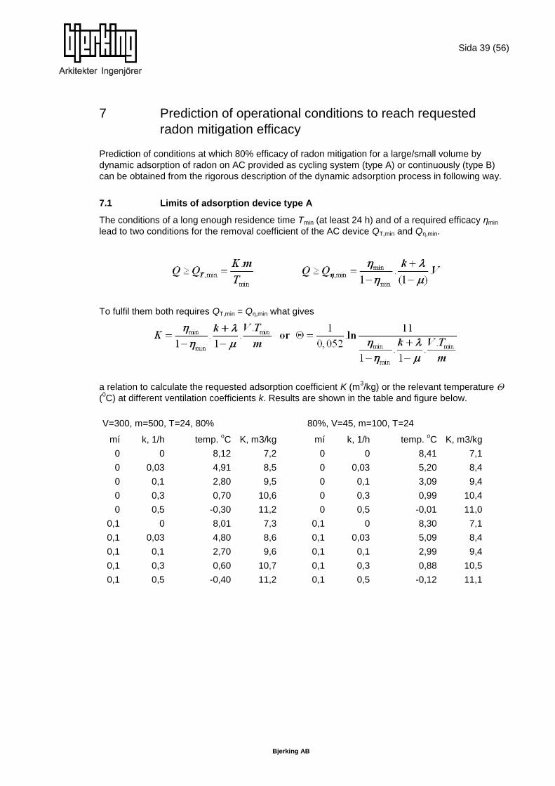
Sida 39 (56)
Bjerking AB
7 Prediction of operational conditions to reach requested
radon mitigation efficacy
Prediction of conditions at which 80% efficacy of radon mitigation for a large/small volume by
dynamic adsorption of radon on AC provided as cycling system (type A) or continuously (type B)
can be obtained from the rigorous description of the dynamic adsorption process in following way.
7.1 Limits of adsorption device type A
The conditions of a long enough residence time Tmin (at least 24 h) and of a required efficacy ηmin
lead to two conditions for the removal coefficient of the AC device QT,min and Qη,min.
To fulfil them both requires QT,min = Qη,min what gives
a relation to calculate the requested adsorption coefficient K (m3/kg) or the relevant temperature
(0C) at different ventilation coefficients k. Results are shown in the table and figure below.
V=300, m=500, T=24, 80% 80%, V=45, m=100, T=24
mí k, 1/h temp. oC K, m3/kg
mí k, 1/h temp.
oC K, m3/kg
0 0 8,12 7,2 0 0 8,41 7,1
0 0,03 4,91 8,5 0 0,03 5,20 8,4
0 0,1 2,80 9,5 0 0,1 3,09 9,4
0 0,3 0,70 10,6 0 0,3 0,99 10,4
0 0,5 -0,30 11,2 0 0,5 -0,01 11,0
0,1 0 8,01 7,3 0,1 0 8,30 7,1
0,1 0,03 4,80 8,6 0,1 0,03 5,09 8,4
0,1 0,1 2,70 9,6 0,1 0,1 2,99 9,4
0,1 0,3 0,60 10,7 0,1 0,3 0,88 10,5
0,1 0,5 -0,40 11,2 0,1 0,5 -0,12 11,1

Sida 40 (56)
Bjerking AB
In all cases the calculated temperature of the AC bed is lower than + 8 0C
Principal properties and limitations of the type A device therefore are:
Also in the case of only 80% efficacy of radon mitigation cooling of the AC bed is requested,
The limiting requirements on cooling and ventilation rates are for this type of operation (in
comparison with type B of operation) similar for large and small devices
7.2 Limits of adsorption device type B
The condition of a required efficacy ηmin and the general relation for the adsorption
lead to an inequality for the volume flow rate Q
(A,B,C “constants” from the van Deemter equation) which is impossible to solve for explicitly. So
first the fraction gained by decay of radon in the AC bed has to be calculated for chosen values
of K and Q. From this inequality limiting conditions for the volume flow rate Q (or the adsorption
coefficient K or for the temperature to reach it) at different ventilation coefficients k results and
results are shown in the table and figure below for with a gray background in the table
and below the decision line on the figure for a great (m=500 kg, V=300 m3) and small (m=100 kg, V
= 45 m3 – the Radon chamber):
-2
0
2
4
6
8
10
0 0,2 0,4 0,6
Co
olin
g te
mp
era
ture
, o
C
ventilation rate k, 1/h
Type A of operation (1 day cycling, limited by-pass μ) Maximal temperature of AC to reach 80% efficacy of radon
mitigation in a house or in the NRPI Rn chamber
V=300, m=500,μ=0
V=300, m=500, μ=0,1
V=45, m=100,μ=0
V=45, m=100,μ=0,1

Sida 41 (56)
Bjerking AB
Great room Calculated Q
Assumed assumed k= k= k= k= k=
K Q n ξ 1-δ 0 0,03 0,1 0,3 0,5
5 1 84 2,25E-01 1,000 9,05 45 129 369 609
5 3 196 3,21E-02 0,998 9,07 45 129 370 610
5 10 346 5,45E-03 0,847 11 53 152 436 719
5 30 360 1,74E-03 0,466 19 97 277 792 1306
5 100 220 8,56E-04 0,172 53 262 751 2149 3546
5 300 98 6,41E-04 0,061 149 740 2120 6062 10004
5 1000 33 5,70E-04 0,019 485 2413 6913 19769 32625
30 1 84 1,35E+00 1,000 9,04800 45 129 369 609
30 3 196 1,92E-01 1,000 9,04800 45 129 369 609
30 10 346 3,27E-02 1,000 9,04813 45,0 129 369 609
30 30 360 1,05E-02 0,976 9,3 46,1 132 378 624
30 100 220 5,13E-03 0,676 13,4 66,6 191 546 900
30 300 98 3,85E-03 0,314 28,9 143,7 412 1177 1942
30 1000 33 3,42E-03 0,107 84,7 421,9 1209 3457 5704
100 1 84 4,50E+00 1,000 9,0 45,0 129 369 609
100 3 196 6,42E-01 1,000 9,048000 45 129 369 609
100 10 346 1,09E-01 1,000 9,048000 45,0 129 369 609
100 30 360 3,49E-02 1,000 9,048039 45,0 129 369 609
100 100 220 1,71E-02 0,976 9,3 46,1 132 378 624
100 300 98 1,28E-02 0,713 12,7 63,2 181 518 854
100 1000 33 1,14E-02 0,313 28,9 144,1 413 1181 1948
250 1 84 1,13E+01 1,000 9,048000 45,0 129 369 609
250 3 196 1,60E+00 1,000 9,048000 45 129 369 609
250 10 346 2,73E-01 1,000 9,048000 45,0 129 369 609
250 30 360 8,72E-02 1,000 9,048000 45,0 129 369 609
250 100 220 4,28E-02 1,000 9,048888 45,1 129 369 609
250 300 98 3,21E-02 0,955 9,5 47,2 135 387 638
250 1000 33 2,85E-02 0,605 15,0 74,4 213 610 1006

Sida 42 (56)
Bjerking AB
1,0
10,0
100,0
1000,0
10000,0
100000,0
1 10 100 1000
Efficiacy 80% is reached only for conditions k and K if calclated Q is below the green DECISION LINE
m=100 kg, V=45 m3
k=0, K=5
k=0.K=30
k=0, K=100
k=0, K=250
k=0,03, K=5
k=0,03, K=30
k=0,03, K=100
k=0,03, K=250
k=0,1, K=5
k=0,1, K=30
k=0,1, K=100
k=0,1, K=250
k=0,3, K=5
k=0,3, K=30
k=0,3, K=100
k=0,3, K=250
k=0,5, K=5
k=0,5, K=30
k=0,5, K=100
k=0,5, K=250
DECISION LINE

Sida 43 (56)
Bjerking AB
Values of K and Q fulfilling the condition of sufficient efficacy of 80% are summarised
(approximately) in figure given below
1
10
100
1000
10000
100000
1 10 100 1000
Cal
cula
ted
Q, m
3/h
Assumed Q, m3/h
Efficacy 80% is reached only for conditions k and K if calclated Q is below the green DECISION LINE
m=500 kg, V=300 m3
k=0, K=5
k=0, K=30
k=0, K=100
k=0, K=250
k=0,03, K=5
k=0,03, K=30
k=0,03, K=100
k=0,03, K=250
k=0,1, K=5
k=0,1, K=30
k=0,1, K=100
k=0,1, K=250
k=0,3, K=5
k=0,3, K=30
k=0,3, K=100
k=0,3, K=250
k=0,5, K=5
k=0,5, K=10
k=0,5, K=100
k=0,5, K=250
DECISION LINE

Sida 44 (56)
Bjerking AB
Limiting parameters of adsorption coefficient K and volume flow Q to reach 80% efficacy of radon
mitigation with 100 kg Ac in a room of 45 m3 or with 500 kg Ac in a room of 300 m
3
(K=250 m3/kg at - 60
oC, K=100 m
3/kg at - 42
oC, K=30 m
3/kg at - 19
oC, K=5 m
3/kg at + 15
oC)
From this summarising of results the general conclusions can be given on the feasibility of radon
mitigation by dynamic adsorption of radon on AC by type B (continuous operation) to reach 80% of
radon mitigation.
Principal properties and limitations of the type B device with continual operation
To reach the same efficacy as the type A of operation the type B requires higher cooling and
higher volume flows
To reach the same efficacy of radon mitigation in a greater volume needs higher cooling and
higher volume flow compared with smaller volumes.
Note: For this prediction values A,B,C from reference KP Strong et al. 1978 have been used which
may not be the same for AC K48 and temperatures below zero.
7.3 Conclusion
Radon mitigation by dynamic adsorption on AC is feasible by both types of operation, the main
condition of it is the cooling.
1
10
100
1000
1 10 100 1000 10000
K, m
3/k
g
Qmin, m3/h
k=0, m=500, V=300
k=0,03, m=500, V=300
k=0,1, m=500, V=300
k=0,3, m=500, V=300
k=0,5, m=500, V=300
k=0, m=100, V=45
k=0,03, m=100, V=45
k=0,1, m=100, V=45
k=0,3, m=100, V=45
k=0,5, m=100, V=45
Sida 45 (56)
Bjerking AB
8 Estimation of radiation protection needs. Study of role of
aerosols.
Based on Czech legislation on radiation protection representing Decree No. 499/2005 Coll.
[A] which is in agreement with the Basic Safety Standards of IAEA the radiological risk connected
with use of AC bed filters should be considered from point of view:
8.1 Active charcoal (AC) bed as a radioactive source
The Decree classify radioactive sources according different criteria and specify disposal conditions
for their holders. To avoid difficulties with “radiation protection point of view” below specify limits
should be fulfilled during AC bed use in any time.
disposal of the active charcoal contaminated by radon and its long-lived transformation
product Pb-210, where exemption limits are prescribed
radionuclide Activity Aex, Bq Mass concentration am,ex, Bq/kg
Rn 222+ 108
104
Pb-210+ 104
104
Note: The sign + means that progeny are present at the level of radioactive progeny
gamma dose rate at 0,1 m from the surface of the AC bed during the operation or at the end of it, where dose rate of 1μSv/h is decisive.
Since more technical details about AC filtering bed and its operation time are missing, only raw
analysis of used AC bed from mentioned classification will be performed. As input data for
calculations we were used maximal acceptable amount of active charcoal and overestimated
operational time.
8.1.1 Rn 222+
The content of radon in the AC bed depends approximately on the amount of charcoal m (kg),
dynamic adsorption coefficient K (m3/kg) and the final radon concentration in the air a (Bq/m
3)
during operation of the AC bed. If the activity A of Rn 222+ is estimated according to formula
A = K x m x a, thus using maximal and acceptable values for all the decisive quantities the result is
A = (5-50) x 500 x 200 = 5 x10⁶ Bq and am ≤ 10
4. So, both the activity exemption level and mass
concentration level would be fulfilled.
8.1.2 Pb 210+
Activity of Pb 210 from the above mentioned situation can be estimated by the accumulation of Pb
210 after long-term , say one year (T) of continuous operation as APb=A x (1-exp(λPb*T)) =
5 x 106 x 0,03 = 15 x10
4 Bq and am ≤ 10
4 Bq/m
3. So, it can be seen that only exemption level is
exceeded by factor 15. Having in mind the fact that maximal values for all decisive quantities are
used, both exemption levels would be fulfilled in real conditions for Pb 210 also.
8.1.3 Gamma dose rate (Ḋg).
The gamma dose rates need to be calculated also for a real construction considering the actual
shape of the AC bed and shielding material used. For orientation dose rates for the nearly spherical
shape of the unshielded AC bed used in our performed experiments type III., with maximal radon
gas input activity A mentioned above are calculated. Then Ḋg = 4 x 10-12
A (attenuation factor) =
4 x 10-12
x 5 x 106x 0,3 = 6 μSv/h. Numerical procedure is in detail listed in appendix 1.
Both the activity and the attenuation factor are overestimated by magnitudes of order. In real
conditions, this could mean that the actual dose rate could be lower than 1 µSv/h and the radiation
risk of irradiation would not be high.

Sida 46 (56)
Bjerking AB
According to Swedish regulations the public cannot be exposed to a radioactive dose exceeding 1
mSv per annum. Based on the calculations above this dose would be exceeded but with the
overestimations made in the assumptions requirements could still be fulfilled in real conditions.
Further testing and research is required to establish need of radiation protection.
8.2 Radioactive waste
The Decree also specifies limits for clearance of radioactive waste. In case of active charcoal
below mentioned clearance limits for radon long-lived transformation products Pb-210 and Po-210
must not be exceed.
disposal of the active charcoal contaminated by radon long-lived transformation products Pb-210 and Po-210 , where clearance limits to environment are prescribed
radionuclide Mass concentration am,Cl Bq/kg
Pb-210+ 3000
Po-210 3000
Note: The sign + has the same meaning as in above mentioned table
Having in mind maximal input parameters of radon accumulated activity in AC bed A = 5 x 10⁶ Bq,
amount of charcoal m= 500kg, during assumed one-year operational time T, then mass
concentration of Pb-210 am,Cl can be calculated as follows: am,Cl = APb /m = A/m x (1-exp(λPb x T))
= 5 x 10⁶/ 500 x 0,03 = 300 Bq/kg. The results indicated that clearance limit for Pb 210 and
evidently for Po 210 also would be fulfilled in real conditions.
According to a proposal on coming regulations in Sweden radioactive waste from households can
be handled as waste with no consideration on radioactivity due to small amounts if the activity is
lower than 10 kBq/kg (lower than 10 times 1 kBq/kg per nuclide in the uranium and torium series).
8.3 Role of aerosols
The lung equivalent dose H from inhalation of short-lived radon progeny can be written by means
of measured time integral of radon concentration as follows:
(1)
where:
DFC is the dose conversion factor [mSv/WLM];
F is the equilibrium factor;
a v is the average radon concentration [Bq/m3];
T exp is the exposition duration [h].
According to currently published calculations by Marsh and Birchall [B], the DFC in Eq. (1) can be
expressed as a linear function of unattached fraction of equilibrium equivalent concentration of
radon progeny fp as follows:
DFC(fp) = 11.35 + 0.43 fp (2)
where fp expressed as the percentage of total potential alpha energy concentration (PAEC) of the
radon progeny mixture.

Sida 47 (56)
Bjerking AB
On principle, AC bed filter during operation can reduce both radon gas concentration and also
aerosol concentration including its spectra. Having in mind also both following published
Pörstendorfer‟s approximate formula [C]:
where:
Z is average indoor aerosol concentration [p/cm3]
and previous equations (1) and (2) it is evident that AC filter bed during its operation can affect
magnitude of lung equivalent dose H and consequently cause excessive risk from increasing of
inhalation dose point of view.
Considering equations (1) and (2) and assuming “the same” breathing rate, the influence of AC
bed filter under operation upon changes of inhalation dose can be expressed in terms of relative
change of equivalent lung dose rate H1/H0 as follows:
with
subscripts 0 and 1 representing ambient conditions during filter ON/OFF operation.
k representing the ratio 11.35/0.43 from equation (2).
η = av1/ avo representing reduction of average value of radon concentration before and after filter
operation.
Since final prototype of AC filtration bed was missing influence its operation upon relative
contribution to equivalent lung dose were demonstrated by means of routine used plastic AC bed,
described in more detail in previous text (see Experiments type III). Used AC bed contained
approximately 70 kg of charcoal type radioiodine and operated with flow rate 21,5 m3/h. This flow
rate corresponded to approximately 0.5 multiple of inner chamber volume exchange rate per hour.
Relative humidity, temperature and air exchange rate ranged in usual indoor scopes (40-60 %),
(20-25º C) and (0,05 – 0.4/h), respectively.
The air exchange rate was continuously monitored by means of the NRPI continuous monitor of
tracer gas nitrous and unattached fraction of radon progeny fp and equilibrium factor F by means of
continuous monitor Fritra 4 as well.
Radon reduction during operation of AC bed ranged from 30% to 70% and the results expressed
in form of desired contribution to relative lung equivalent dose calculated according to equation (4)
can be seen in the Fig.1. As a reference values Fo,fpo in equation (4) was chosen 0,3 and 0,09
respectively usually measured in houses. [D],[E].

Sida 48 (56)
Bjerking AB
Fig. 1 The influence of air exchange rate on contribution to equivalent lung dose during
operation of AC bed filter in NRPI radon chamber.
The results indicated that application of the AC bed did not cause any excessive risk from
inhalation lung equivalent dose point of view and AC bed can be used as a radon remedial tool.
0
0,2
0,4
0,6
0,8
1
0,023 0,05 0,07 0,4
con
trib
uti
on
H1
/Ho
air exchange rate (h-1)
Influence of AC bed filtering upon rel. contribution to equivalent dose H1/Ho. AC type iodine m=70kg, q=21,5m3/h.
NRPI Radon chamber

Sida 49 (56)
Bjerking AB
9 Conclusion and future plans
The original proposal (see items in Introduction) is covered in details in previous chapters. The
obtained results of the project will mainly be used in the consequent steps.
The next step would be constructing a prototype. Since the crucial point seems to be energy
consumption for cooling the charcoal the first step could be to build such a prototype without
cooling system. This prototype would be an example of an apparatus that can be placed outdoors,
where the cooling could be natural, from the outdoor air, to minimize energy consumption. In the
next step the possibility to use a non continuous performance system with charcoal regeneration to
increase efficiency should be analyzed. The prototype could be built and tested in the NRPI radon
chamber under controlled conditions. It is also possible in a second step to test it under real
conditions in a family house, for example in Sweden.
The results from experiments indicate that the charcoal trap is more efficient during low air
exchange rate. Hence, it is proposed to aim for poorly ventilated houses with this solution for radon
suppressing. As described in chapter 3, there are several cost effective methods to suppress radon
from the ground whereas reducing radon concentration in houses where the construction material
is the source can be more difficult and costly. Therefore it is suggested to concentrate on the
charcoal trap for houses with radon mainly from the construction material as an alternative to
installing a mechanical ventilation system.
In continuing experiments the ability for activated charcoal to adsorb not only radon but also
pollutants in the indoor air can be tested. If this proves successful it would give the charcoal trap an
advantage compared to other radon suppressing methods.
A future plan is also to integrate the charcoal bed system with a device for radon measurement,
which could automatically detect radon concentrations and control the charcoal cleaning system.
Appendixes
Appendix 1. Mitigation ratio vs ventilation rate
Appendix 2. The dose rate of gamma radiation near the adsorption device.

Sida 50 (56)
Bjerking AB
References
N.M.Rahman and B.L.Tracy: Radon control systems in existing and new houses: A review. In:
Radiation Protection Dosimetry (2009), Vol. 135, No. 4, pp.243-255
K.V.Liu, J.D.Gabor, R.E.Holtz and K.C.Gross: Fluid-based radon mitigation technology
developement for industrial applications, Argone National Laboratory, Illinois
Thomas Coskeran, Antony Denman, Paul Phillips: The costs of radon mitigation in domestic
properties. In: Health Policy 57 (2001) 97–109
Thomas Coskeran, Antony Denman, Paul Phillips, Roger Tornberg: The cost-effectiveness of
radon-proof membranes in new homes: A case study from Brixworth, Northamptonshire, UK. In:
Health Policy 81 (2007) 195–206
Mads Lyngby Petersen, Thommy Larsen: Cost–benefit analyses of radon mitigation projects. In:
Journal of Environmental Management 81 (2006) 19–26
Jiránek M., Rovenská K.: Limited applicability of cost-effectiveness and cost-benefit analyses for
the optimization of radon remedial measures. In: Hazardous Materials, Volume 182, Issues 1-3, pp.
439-446, doi:10.1016/j.jhazmat.2010.06.051
P. Wasiolek; N. Montassier; P. K. Hopke; R. Abrams: Analysis of the performance of a radon
mitigation system based on charcoal beds Environ. Technol. Letters 14:401-412 (1993).
Holmgren O., Arvela H., et al.: Assessment of current techniques used for reduction of indoor
radon concentration in existing and new houses. Report prepared for RADPAR project, STUK
Helsinki, 2010
Decree on radiation protection No.499/2005 Coll, State Office for Nuclear Safety, NUKLIN, Prague,
2005.
Marsh JW, Birchall A. Sensitivity analysis of the weighted equivalent lung dose per unit exposure
from radon progeny. Radiat. Protection Dosimetry 2000; 87(3):167-178.
Porstendörfer J. Influence of physical parameters on doses from radon exposures, In:
Burkart W, Sohrabi M, Bayer A (Eds.). Proceedings on 5th
International Conference on High Levels
of Natural radiation and radon areas. 2000 Sept 4-7; Munich, Germany, Elsevier, 2002, p. 149 –
160.
Porstendörfer J. Behaviour of radon daughter products in indoor air, Radiat. Protection Dosimetry,
1984; 7(1-4):107-113.
Jilek K, Thoms J, Tomasek L. First results of measurement of equilibrium factors F and unattached fractions fp of radon progeny in Czech dwellings, Nukleonika, 2010;55(4):439−444. O
WHO Handbook of Indoor Radon, World Health Organization, 2010.
Super-Kamiokande Collaboration, Physics Letters B 452 (1999) 418.
Clavensjö, B., Åkerblom, G. 2007; Radonboken, åtgärder mot radon i befintliga byggnader
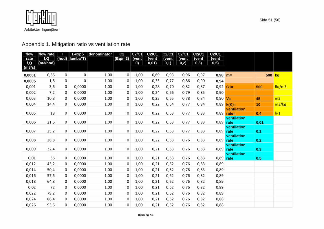
Sida 51 (56)
Bjerking AB
Appendix 1. Mitigation ratio vs ventilation rate
flow rate f,Q
(m3/s)
flow rate f,Q
(m3/hod)
T (hod)
1-exp(-lamba*T)
denominator C2 (Bq/m3)
C2/C1 (vent
0)
C2/C1 (vent 0,01)
C2/C1 (vent 0,1)
C2/C1 (vent 0,2)
C2/C1 (vent 0,3)
C2/C1 (vent 0,5)
0,0001 0,36 0 0 1,00 0 1,00 0,69 0,93 0,96 0,97 0,98 m= 500 kg
0,0005 1,8 0 0 1,00 0 1,00 0,35 0,77 0,86 0,90 0,94
0,001 3,6 0 0,0000 1,00 0 1,00 0,28 0,70 0,82 0,87 0,92 C1= 500 Bq/m3
0,002 7,2 0 0,0000 1,00 0 1,00 0,24 0,66 0,79 0,85 0,90
0,003 10,8 0 0,0000 1,00 0 1,00 0,23 0,65 0,78 0,84 0,90 V= 45 m3
0,004 14,4 0 0,0000 1,00 0 1,00 0,22 0,64 0,77 0,84 0,89 k(K)= 10 m3/kg
0,005 18 0 0,0000 1,00 0 1,00 0,22 0,63 0,77 0,83 0,89 ventilation rate= 0,4 h-1
0,006 21,6 0 0,0000 1,00 0 1,00 0,22 0,63 0,77 0,83 0,89 ventilation rate 0,01
0,007 25,2 0 0,0000 1,00 0 1,00 0,22 0,63 0,77 0,83 0,89
ventilation rate 0,1
0,008 28,8 0 0,0000 1,00 0 1,00 0,22 0,63 0,76 0,83 0,89
ventilation rate 0,2
0,009 32,4 0 0,0000 1,00 0 1,00 0,21 0,63 0,76 0,83 0,89
ventilation rate 0,3
0,01 36 0 0,0000 1,00 0 1,00 0,21 0,63 0,76 0,83 0,89
ventilation rate 0,5
0,012 43,2 0 0,0000 1,00 0 1,00 0,21 0,62 0,76 0,83 0,89 0,014 50,4 0 0,0000 1,00 0 1,00 0,21 0,62 0,76 0,83 0,89 0,016 57,6 0 0,0000 1,00 0 1,00 0,21 0,62 0,76 0,82 0,89 0,018 64,8 0 0,0000 1,00 0 1,00 0,21 0,62 0,76 0,82 0,89 0,02 72 0 0,0000 1,00 0 1,00 0,21 0,62 0,76 0,82 0,89 0,022 79,2 0 0,0000 1,00 0 1,00 0,21 0,62 0,76 0,82 0,89 0,024 86,4 0 0,0000 1,00 0 1,00 0,21 0,62 0,76 0,82 0,88 0,026 93,6 0 0,0000 1,00 0 1,00 0,21 0,62 0,76 0,82 0,88

Sida 52 (56)
Bjerking AB
flow rate f,Q
(m3/s)
flow rate f,Q
(m3/hod)
T (hod)
1-exp(-lamba*T)
denominator C2 (Bq/m3)
C2/C1 (vent
0)
C2/C1 (vent 0,01)
C2/C1 (vent 0,1)
C2/C1 (vent 0,2)
C2/C1 (vent 0,3)
C2/C1 (vent 0,5)
0,028 100,8 0 0,0000 1,00 0 1,00 0,21 0,62 0,76 0,82 0,88 0,03 108 0 0,0000 1,00 0 1,00 0,21 0,62 0,76 0,82 0,88 0,04 144 0 0,0000 1,00 0 1,00 0,21 0,62 0,76 0,82 0,88 0,05 180 0 0,0000 1,00 0 1,00 0,21 0,62 0,76 0,82 0,88 0,06 216 0 0,0000 1,00 0 1,00 0,21 0,62 0,76 0,82 0,88 0,07 252 0 0,0000 1,00 0 1,00 0,21 0,62 0,76 0,82 0,88 0,08 288 0 0,0000 1,00 0 1,00 0,21 0,62 0,76 0,82 0,88 0,09 324 0 0,0000 1,00 0 1,00 0,21 0,62 0,76 0,82 0,88 0,1 360 0 0,0000 1,00 0 1,00 0,21 0,62 0,76 0,82 0,88 0,11 396 0 0,0000 1,00 0 1,00 0,21 0,62 0,76 0,82 0,88 0,12 432 0 0,0000 1,00 0 1,00 0,21 0,62 0,76 0,82 0,88 0,13 468 0 0,0000 1,00 0 1,00 0,21 0,62 0,76 0,82 0,88 0,14 504 0 0,0000 1,00 0 1,00 0,21 0,62 0,76 0,82 0,88 0,15 540 0 0,0000 1,00 0 1,00 0,21 0,62 0,76 0,82 0,88 0,16 576 0 0,0000 1,00 0 1,00 0,21 0,62 0,76 0,82 0,88 0,17 612 0 0,0000 1,00 0 1,00 0,21 0,62 0,76 0,82 0,88 0,18 648 0 0,0000 1,00 0 1,00 0,21 0,62 0,76 0,82 0,88 0,19 684 0 0,0000 1,00 0 1,00 0,21 0,62 0,76 0,82 0,88 0,2 720 0 0,0000 1,00 0 1,00 0,21 0,62 0,76 0,82 0,88 0,21 756 0 0,0000 1,00 0 1,00 0,21 0,62 0,76 0,82 0,88 0,22 792 0 0,0000 1,00 0 1,00 0,21 0,62 0,76 0,82 0,88 0,23 828 0 0,0000 1,00 0 1,00 0,21 0,62 0,76 0,82 0,88 0,24 864 0 0,0000 1,00 0 1,00 0,21 0,62 0,76 0,82 0,88 0,25 900 0 0,0000 1,00 0 1,00 0,21 0,62 0,76 0,82 0,88

Sida 53 (56)
Bjerking AB
0
0,1
0,2
0,3
0,4
0,5
0,6
0,7
0,8
0,9
1
0 10 20 30 40 50 60 70 80 90 100
C2
/C1
flow rate m3/h
Dependence of mitigation ratio c2/c1d on flow rate
for m=100 kg, k=4 m3/kg, V=45 m3
0
0,2
0,4
0,6
0,8
1
1,2
0 20 40 60 80 100
C2/c
1
flow rate m3/h
Dependence of mitigation ratio c2/c1d on flow rate for m=500 kg
0
100
200
300
400
500
600
0 20 40 60 80 100
C B
q/m
3
flow rate m3/h
Dependence of Rn concentration on flow rate m=500 kg

Sida 54 (56)
Bjerking AB
Appendix 2
The dose rate of gamma radiation near the adsorption device
The dose rate D [Gy/h] of radon progeny adsorbed on activated charcoal is possible to determine
applying the known rule for the dose rate of a point source A [Bq] of Ra 226 in distance r [m]
from the source
(4.1)
where = 2,51/-13 (Gy.m2)/(h.Bq) is the gamma constant of Ra 226 (in equilibrium with radon and
its progeny). The geometrical shape of non-point sources and the self-absorption has to be
considered. The equilibrium of the radon progeny in the AC is not the same as in hermetically
sealed radium sources but the deviation can be neglected in this orientation study, we think so.
The geometry of the adsorption bed used in the Radon chamber is best approximated by a sphere
with an equivalent radius
The attenuation coefficient of gamma radiation = 7,1E-3 m
2/kg in carbon for mean energy 0,78
MeV of radon progeny can be used. So the mean free path of gamma photons in a sphere with
radius R = 0,247 m is m.R = 0,875.
According to the Compendium (RG Jaeger, editor, Engineering Compendium on Radiation
Shielding, Vol.1, equ. (6.4-55), 1968) the fluence rate of gamma photons on the surface of a
contaminated absorbing sphere is
(4.2)
(4.3)
Transformed to dose rate (4.4)
with [Bq] activity of radon in the bed in steady state, 335 Bq/m3, V = 45 m
3.
In the same Compendium is (equ. 6.4-53) a numerical relation for the dose rate at the distance a
(up to 2 m) from the surface of a sphere
(4.5)
Transformed to dose rate
. (4.6)
From the table (Table 6.4.-4.) it is possible to get the shape correction G(p;0,875). In the table
below are given dose rates for the actual AC bed used in the Radon chamber. Extrapolation
to a = 0 is not sure, also due to that that the shape of the actual adsorption bed is quite different
from a sphere), so it is only an orientation number, but near to that calculated directly.
p a [m] G(p;0,875) D [Gy/h]
1 0 (0,8) (0,44)
1,25 0,0625 0,45 0,26
1,5 0,123 0,29 0,17
2 0,25 0,155 0,09
3 0,49 0,066 0,04
5 1,0 0,023 0,013
10 2,2 0,0058 0,004

Sida 55 (56)
Bjerking AB
As an actual example the dose rate from the adsorption bed in Experiment No. 4 CHAMBER with
AC K48 (IETP) (ventilation coefficient k = 0,14/h, staca = 335 Bq/m3)is given. The deposited activity
A [Bq] of radon is derived in chapter 3
(4.7)
When measuring gamma dose rates in the chamber contaminated with radon progeny in the
air and on the walls the contribution to the dose rate from the radon bed has to be known. The
Compendium gives fluence rate in the centre of an absorbing sphere (equ.6.4.-56) (4.8)
which changes without absorption (air) to therefore the dose rate is (4.9)
with [Bq] the activity of radon in the chamber of 45 m3, and an equivalent radius
R = 2,2 m.
But the Compendium does not give the fluence rate in the centre of the sphere from contamination
of the wall Sb [Bq/m2]. It‟s possible to derive it as
(4.10)
Experimental results for the gamma dose rate
During the experiment in the radon chamber (No. 4) these dose rates (including the background)
were measured:
- 0,4 μGy/h on the surface of the AC bed, range 0,25 – 0,55 μGy/h (compared with the
calculated value 0,54 μGy/h)
- 0,18 μGy/h 2 m apart the AC bed, about the centre of the chamber, range 0,14 – 0,22
μGy/h (here the common background of 0,15 μGy/h dominates)
- 0,16 μGy/h on the walls of the chamber, range 0,14 – 0,18 μGy/h (here the background of
0,1x μGy/h dominates also)

Sida 56 (56)
Bjerking AB
Within a factor of two the measured and calculated (including the estimation of the activity
contained in the AC bed) gamma dose rates are in agreement. For better agreement higher
concentrations in the Radon chamber are needed.