Embed Size (px)
Citation preview
368
SLI
O10
0V20
0V30
0S50
0SH
MI
Sof
twar
eA
cces
sorie
sA
ppen
dix
300S | CPUs
CPUs
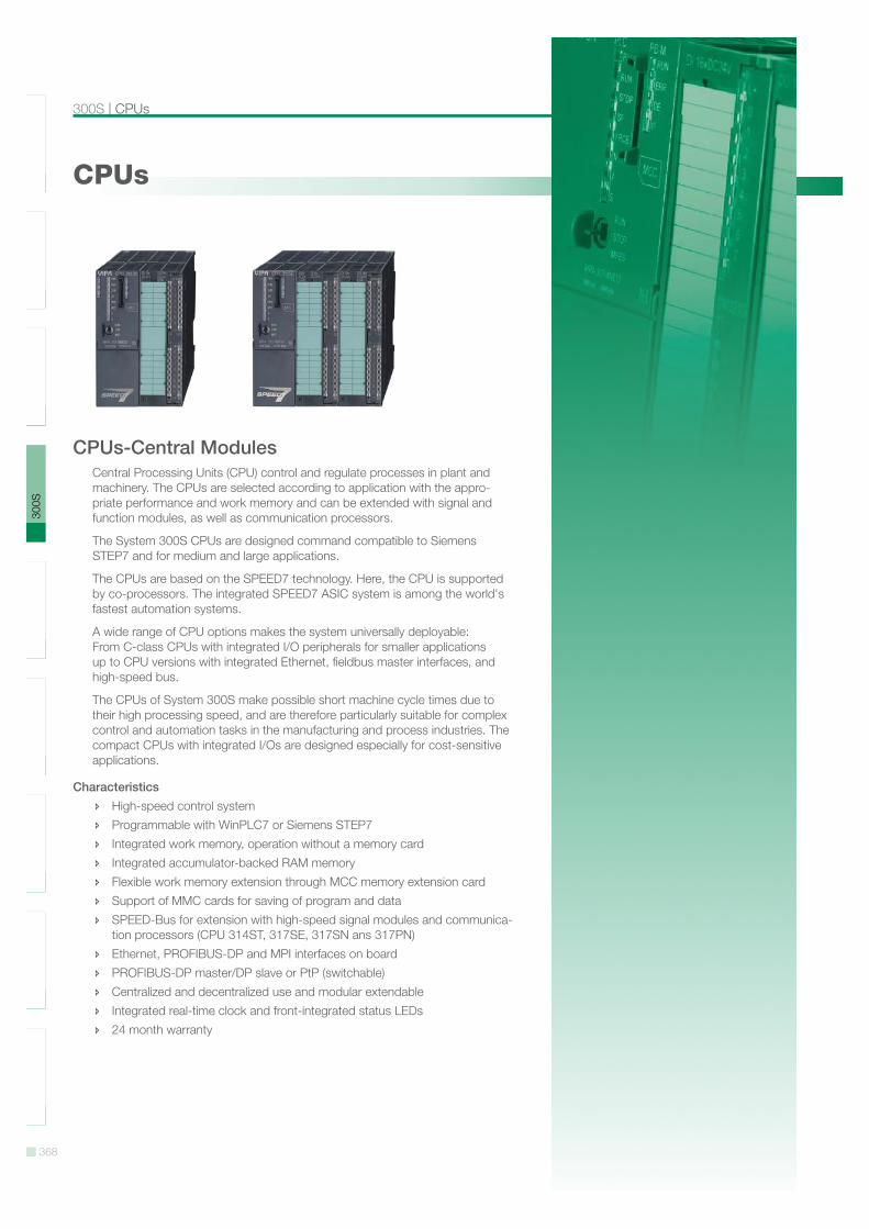
CPUs-Central Modules Central Processing Units (CPU) control and regulate processes in plant and machinery. The CPUs are selected according to application with the appro-priate performance and work memory and can be extended with signal and function modules, as well as communication processors.
The System 300S CPUs are designed command compatible to Siemens STEP7 and for medium and large applications.
The CPUs are based on the SPEED7 technology. Here, the CPU is supported by co-processors. The integrated SPEED7 ASIC system is among the world's fastest automation systems.
A wide range of CPU options makes the system universally deployable: From C-class CPUs with integrated I/O peripherals for smaller applications up to CPU versions with integrated Ethernet, fieldbus master interfaces, and high-speed bus.
The CPUs of System 300S make possible short machine cycle times due to their high processing speed, and are therefore particularly suitable for complex control and automation tasks in the manufacturing and process industries. The compact CPUs with integrated I/Os are designed especially for cost-sensitive applications.
Characteristics High-speed control system Programmable with WinPLC7 or Siemens STEP7 Integrated work memory, operation without a memory card Integrated accumulator-backed RAM memory Flexible work memory extension through MCC memory extension card Support of MMC cards for saving of program and data SPEED-Bus for extension with high-speed signal modules and communica-
tion processors (CPU 314ST, 317SE, 317SN ans 317PN) Ethernet, PROFIBUS-DP and MPI interfaces on board PROFIBUS-DP master/DP slave or PtP (switchable) Centralized and decentralized use and modular extendable Integrated real-time clock and front-integrated status LEDs 24 month warranty
369
SLI
O10
0V20
0V30
0S50
0SH
MI
Sof
twar
eA
cces
sorie
sA
ppen
dix
Overview | CPUs
Overview
Order no. Name/Description PageCPUs STEP7 programmable, standard314-2AG12 CPU 314SB/DPM - SPEED7 technology 371
SPEED7 technology 256 kB work memory Memory extension (max. 512 kB) PROFIBUS-DP master / PtP (switchable)
314-2AG13 CPU 314SB/DPM - SPEED7 technology 371 SPEED7 technology 256 kB work memory Memory extension (max. 512 kB) PROFIBUS-DP master / PtP (switchable) Configurable via TIA-Portal
314-2BG03 CPU 314SE/DPS - SPEED7 technology 371 SPEED7 technology 128 kB work memory Memory extension (max. 512 kB) PROFIBUS-DP slave / PtP (switchable) Configurable via TIA-Portal
315-2AG12 CPU 315SB/DPM - SPEED7 technology 371 SPEED7 technology 1 MB work memory Memory extension (max. 2 MB) PROFIBUS-DP master / PtP (switchable)
315-2AG13 CPU 315SB/DPM - SPEED7 technology 378 SPEED7 technology 1 MB work memory Memory extension (max. 2 MB) PROFIBUS-DP master / PtP (switchable) Configurable via TIA-Portal
317-2AJ12 CPU 317SE/DPM - SPEED7 technology 378 SPEED7 technology, SPEED-Bus 2 MB work memory Memory extension (max. 8 MB) PROFIBUS-DP master / PtP (switchable)
317-2AJ13 CPU 317SE/DPM - SPEED7 technology 378 SPEED7 technology, SPEED-Bus 2 MB work memory Memory extension (max. 8 MB) PROFIBUS-DP master / PtP (switchable) Configurable via TIA-Portal
CPUs STEP7 programmable, NET-CPUs315-4NE12 CPU 315SN/NET - SPEED7 technology 385
SPEED7 technology 1 MB work memory Memory extension (max. 2 MB) PROFIBUS-DP master / PtP (switchable) CP 343 integrated
315-4NE13 CPU 315SN/NET - SPEED7 technology 385 SPEED7 technology 1 MB work memory Memory extension (max. 2 MB) PROFIBUS-DP master / PtP (switchable) CP 343 integrated Configurable via TIA-Portal
317-4NE12 CPU 317SN/NET - SPEED7 technology 385 SPEED7 technology, SPEED-Bus 2 MB work memory Memory extension (max. 8 MB) PROFIBUS-DP master / PtP (switchable) CP 343 integrated
317-4NE13 CPU 317SN/NET - SPEED7 technology 385 SPEED7 technology, SPEED-Bus 2 MB work memory Memory extension (max. 8 MB) PROFIBUS-DP master / PtP (switchable) CP 343 integrated Configurable via TIA-Portal
370
SLI
O10
0V20
0V30
0S50
0SH
MI
Sof
twar
eA
cces
sorie
sA
ppen
dix
CPUs STEP7 programmable, standard | Overview
Overview
Order no. Name/Description PageCPUs STEP7 programmable, PROFINET315-4PN12 CPU 315SN/NET - SPEED7 technology 393
SPEED7 technology 1 MB work memory Memory extension (max. 2 MB) PROFIBUS-DP master / PtP (switchable) PROFINET controller integrated Configurable via TIA-Portal
315-4PN33 CPU 315SN/NET ECO - SPEED7 technology 393 SPEED7 technology 512 KB work memory PtP PROFINET controller integrated Configurable via TIA-Portal Available at Q4/2012
317-4PN12 CPU 317SN/NET - SPEED7 technology 393 SPEED7 technology, SPEED-Bus 2 MB work memory Memory extension (max. 8 MB) PROFIBUS-DP master / PtP (switchable) PROFINET Controller integrated Configurable via TIA-Portal
CPUs STEP7 programmable, class C312-5BE13 CPU 312SC - SPEED7 technology 401
SPEED7 technology 16 x DI, 8 x DO 64 kB work memory Memory extension (max. 512 kB) PtP interface Configurable via TIA-Portal
313-5BF13 CPU 313SC - SPEED7 technology 401 SPEED7 technology 24 x DI, 16 x DO, 4 x AI, 2 x AO, 1xAI Pt100 128 kB work memory Memory extension (max. 512 kB) PtP interface Configurable via TIA-Portal
313-6CF13 CPU 313SC/DPM - SPEED7 technology 401 SPEED7 technology 16 x DI, 16 x DO 128 kB work memory Memory extension (max 512 kB) PROFIBUS-DP master / PtP (switchable) Configurable via TIA-Portal
314-6CF02 CPU 314ST/DPM - SPEED7 technology 401 SPEED7 technology, SPEED-Bus 8 x DI, 8 x DO, 4 x AI, 2 x AO, 1xAI Pt100 512 kB work memory Memory extension (max. 2 MB) PROFIBUS-DP master / PtP (switchable)
314-6CF03 CPU 314ST/DPM - SPEED7 technology 412 SPEED7 technology, SPEED-Bus 8 x DI, 8 x DO, 4 x AI, 2 x AO, 1xAI Pt100 512 kB work memory Memory extension (max. 2 MB) PROFIBUS-DP master / PtP (switchable) Configurable via TIA-Portal
314-6CG13 CPU 314SC/DPM - SPEED7 technology 412 SPEED7 technology 24 x DI, 16 x DO, 8 x DIO, 4 x AI, 1 x AI Pt100, 2xAO 256 kB work memory Memory extension (max. 1 MB) PROFIBUS-DP master / PtP (switchable) Configurable via TIA-Portal
371
SLI
O10
0V20
0V30
0S50
0SH
MI
Sof
twar
eA
cces
sorie
sA
ppen
dix
CPUs STEP7 programmable, standard | CPUs
CPUs | CPUs STEP7 programmable, standard314-2AG12314-2AG13314-2BG03315-2AG12
315-2AG13317-2AJ12317-2AJ13
CPUs STEP7 programmable, standard
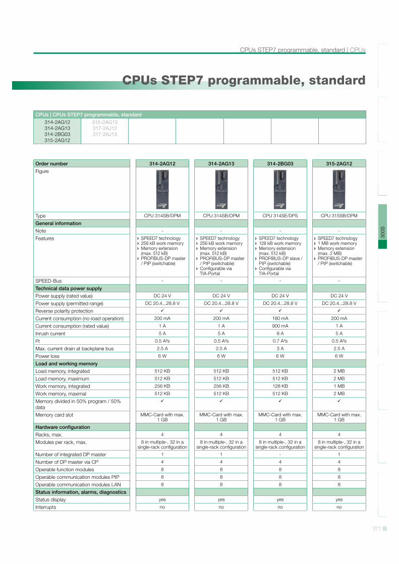
Order number 314-2AG12 314-2AG13 314-2BG03 315-2AG12Figure
Type CPU 314SB/DPM CPU 314SB/DPM CPU 314SE/DPS CPU 315SB/DPM
General informationNote - - - -
Features SPEED7 technology 256 kB work memory Memory extension (max. 512 kB)
PROFIBUS-DP master / PtP (switchable)
SPEED7 technology 256 kB work memory Memory extension (max. 512 kB)
PROFIBUS-DP master / PtP (switchable)
Configurable via TIA-Portal
SPEED7 technology 128 kB work memory Memory extension (max. 512 kB)
PROFIBUS-DP slave / PtP (switchable)
Configurable via TIA-Portal
SPEED7 technology 1 MB work memory Memory extension (max. 2 MB)
PROFIBUS-DP master / PtP (switchable)
SPEED-Bus - - - -
Technical data power supplyPower supply (rated value) DC 24 V DC 24 V DC 24 V DC 24 V
Power supply (permitted range) DC 20.4...28.8 V DC 20.4...28.8 V DC 20.4...28.8 V DC 20.4...28.8 V
Reverse polarity protectionCurrent consumption (no-load operation) 200 mA 200 mA 180 mA 200 mA
Current consumption (rated value) 1 A 1 A 900 mA 1 A
Inrush current 5 A 5 A 8 A 5 A
I!t 0.5 A!s 0.5 A!s 0.7 A!s 0.5 A!s
Max. current drain at backplane bus 2.5 A 2.5 A 3 A 2.5 A
Power loss 6 W 6 W 6 W 6 W
Load and working memoryLoad memory, integrated 512 KB 512 KB 512 KB 2 MB
Load memory, maximum 512 KB 512 KB 512 KB 2 MB
Work memory, integrated 256 KB 256 KB 128 KB 1 MB
Work memory, maximal 512 KB 512 KB 512 KB 2 MB
Memory divided in 50% program / 50% dataMemory card slot MMC-Card with max.
1 GBMMC-Card with max.
1 GBMMC-Card with max.
1 GBMMC-Card with max.
1 GB
Hardware configurationRacks, max. 4 4 4 4
Modules per rack, max. 8 in multiple-, 32 in a single-rack configuration
8 in multiple-, 32 in a single-rack configuration
8 in multiple-, 32 in a single-rack configuration
8 in multiple-, 32 in a single-rack configuration
Number of integrated DP master 1 1 - 1
Number of DP master via CP 4 4 4 4
Operable function modules 8 8 8 8
Operable communication modules PtP 8 8 8 8
Operable communication modules LAN 8 8 8 8
Status information, alarms, diagnosticsStatus display yes yes yes yes
Interrupts no no no no
372
SLI
O10
0V20
0V30
0S50
0SH
MI
Sof
twar
eA
cces
sorie
sA
ppen
dix
CPUs | CPUs STEP7 programmable, standard
CPUs | CPUs STEP7 programmable, standard314-2AG12314-2AG13314-2BG03315-2AG12
315-2AG13317-2AJ12317-2AJ13
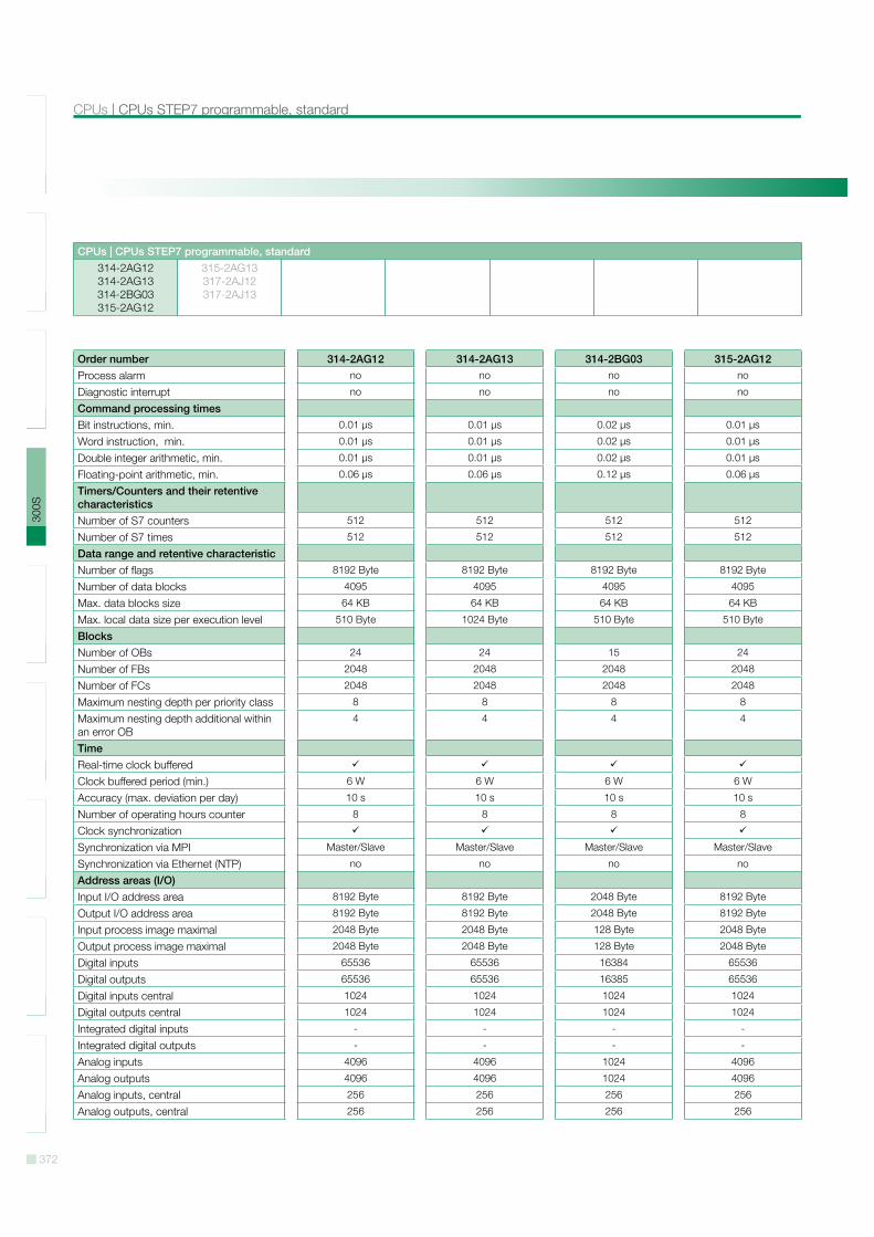
Order number 314-2AG12 314-2AG13 314-2BG03 315-2AG12Process alarm no no no no
Diagnostic interrupt no no no no
Command processing timesBit instructions, min. 0.01 µs 0.01 µs 0.02 µs 0.01 µs
Word instruction, min. 0.01 µs 0.01 µs 0.02 µs 0.01 µs
Double integer arithmetic, min. 0.01 µs 0.01 µs 0.02 µs 0.01 µs
Floating-point arithmetic, min. 0.06 µs 0.06 µs 0.12 µs 0.06 µs
Timers/Counters and their retentive characteristicsNumber of S7 counters 512 512 512 512
Number of S7 times 512 512 512 512
Data range and retentive characteristicNumber of flags 8192 Byte 8192 Byte 8192 Byte 8192 Byte
Number of data blocks 4095 4095 4095 4095
Max. data blocks size 64 KB 64 KB 64 KB 64 KB
Max. local data size per execution level 510 Byte 1024 Byte 510 Byte 510 Byte
BlocksNumber of OBs 24 24 15 24
Number of FBs 2048 2048 2048 2048
Number of FCs 2048 2048 2048 2048
Maximum nesting depth per priority class 8 8 8 8
Maximum nesting depth additional within an error OB
4 4 4 4
TimeReal-time clock bufferedClock buffered period (min.) 6 W 6 W 6 W 6 W
Accuracy (max. deviation per day) 10 s 10 s 10 s 10 s
Number of operating hours counter 8 8 8 8
Clock synchronizationSynchronization via MPI Master/Slave Master/Slave Master/Slave Master/Slave
Synchronization via Ethernet (NTP) no no no no
Address areas (I/O)Input I/O address area 8192 Byte 8192 Byte 2048 Byte 8192 Byte
Output I/O address area 8192 Byte 8192 Byte 2048 Byte 8192 Byte
Input process image maximal 2048 Byte 2048 Byte 128 Byte 2048 Byte
Output process image maximal 2048 Byte 2048 Byte 128 Byte 2048 Byte
Digital inputs 65536 65536 16384 65536
Digital outputs 65536 65536 16385 65536
Digital inputs central 1024 1024 1024 1024
Digital outputs central 1024 1024 1024 1024
Integrated digital inputs - - - -
Integrated digital outputs - - - -
Analog inputs 4096 4096 1024 4096
Analog outputs 4096 4096 1024 4096
Analog inputs, central 256 256 256 256
Analog outputs, central 256 256 256 256
373
SLI
O10
0V20
0V30
0S50
0SH
MI
Sof
twar
eA
cces
sorie
sA
ppen
dix
CPUs STEP7 programmable, standard | CPUs
CPUs | CPUs STEP7 programmable, standard314-2AG12314-2AG13314-2BG03315-2AG12
315-2AG13317-2AJ12317-2AJ13
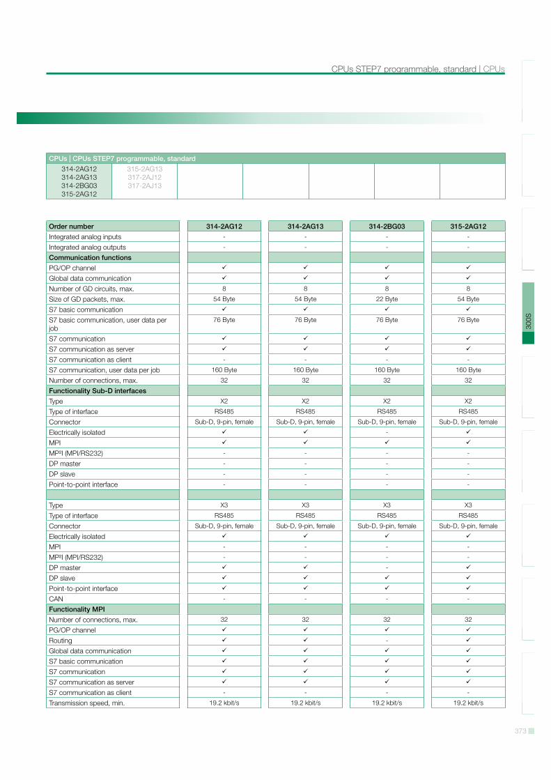
Order number 314-2AG12 314-2AG13 314-2BG03 315-2AG12Integrated analog inputs - - - -
Integrated analog outputs - - - -
Communication functionsPG/OP channelGlobal data communicationNumber of GD circuits, max. 8 8 8 8
Size of GD packets, max. 54 Byte 54 Byte 22 Byte 54 Byte
S7 basic communicationS7 basic communication, user data per job
76 Byte 76 Byte 76 Byte 76 Byte
S7 communicationS7 communication as serverS7 communication as client - - - -
S7 communication, user data per job 160 Byte 160 Byte 160 Byte 160 Byte
Number of connections, max. 32 32 32 32
Functionality Sub-D interfacesType X2 X2 X2 X2
Type of interface RS485 RS485 RS485 RS485
Connector Sub-D, 9-pin, female Sub-D, 9-pin, female Sub-D, 9-pin, female Sub-D, 9-pin, female
Electrically isolated -
MPIMP!I (MPI/RS232) - - - -
DP master - - - -
DP slave - - - -
Point-to-point interface - - - -
Type X3 X3 X3 X3
Type of interface RS485 RS485 RS485 RS485
Connector Sub-D, 9-pin, female Sub-D, 9-pin, female Sub-D, 9-pin, female Sub-D, 9-pin, female
Electrically isolatedMPI - - - -
MP!I (MPI/RS232) - - - -
DP master -
DP slavePoint-to-point interfaceCAN - - - -
Functionality MPINumber of connections, max. 32 32 32 32
PG/OP channelRouting -
Global data communicationS7 basic communicationS7 communicationS7 communication as serverS7 communication as client - - - -
Transmission speed, min. 19.2 kbit/s 19.2 kbit/s 19.2 kbit/s 19.2 kbit/s
374
SLI
O10
0V20
0V30
0S50
0SH
MI
Sof
twar
eA
cces
sorie
sA
ppen
dix
CPUs | CPUs STEP7 programmable, standard
CPUs | CPUs STEP7 programmable, standard314-2AG12314-2AG13314-2BG03315-2AG12
315-2AG13317-2AJ12317-2AJ13
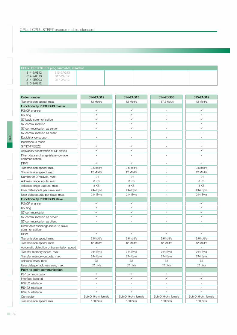
Order number 314-2AG12 314-2AG13 314-2BG03 315-2AG12Transmission speed, max. 12 Mbit/s 12 Mbit/s 187.5 kbit/s 12 Mbit/s
Functionality PROFIBUS masterPG/OP channel -
Routing -
S7 basic communication -
S7 communication -
S7 communication as server -
S7 communication as client - - - -
Equidistance support - - - -
Isochronous mode - - - -
SYNC/FREEZE -
Activation/deactivation of DP slaves -
Direct data exchange (slave-to-slave communication)
- - - -
DPV1 -
Transmission speed, min. 9.6 kbit/s 9.6 kbit/s - 9.6 kbit/s
Transmission speed, max. 12 Mbit/s 12 Mbit/s - 12 Mbit/s
Number of DP slaves, max. 124 124 - 124
Address range inputs, max. 8 KB 8 KB - 8 KB
Address range outputs, max. 8 KB 8 KB - 8 KB
User data inputs per slave, max. 244 Byte 244 Byte - 244 Byte
User data outputs per slave, max. 244 Byte 244 Byte - 244 Byte
Functionality PROFIBUS slavePG/OP channel -
Routing -
S7 communication -
S7 communication as server -
S7 communication as client - - - -
Direct data exchange (slave-to-slave communication)
- - - -
DPV1Transmission speed, min. 9.6 kbit/s 9.6 kbit/s 9.6 kbit/s 9.6 kbit/s
Transmission speed, max. 12 Mbit/s 12 Mbit/s 12 Mbit/s 12 Mbit/s
Automatic detection of transmission speed - - - -
Transfer memory inputs, max. 244 Byte 244 Byte 244 Byte 244 Byte
Transfer memory outputs, max. 244 Byte 244 Byte 244 Byte 244 Byte
Address areas, max. 32 32 32 32
User data per address area, max. 32 Byte 32 Byte 32 Byte 32 Byte
Point-to-point communicationPtP communicationInterface isolatedRS232 interface - - - -
RS422 interface - - - -
RS485 interfaceConnector Sub-D, 9-pin, female Sub-D, 9-pin, female Sub-D, 9-pin, female Sub-D, 9-pin, female
Transmission speed, min. 150 bit/s 150 bit/s 150 bit/s 150 bit/s
375
SLI
O10
0V20
0V30
0S50
0SH
MI
Sof
twar
eA
cces
sorie
sA
ppen
dix
CPUs STEP7 programmable, standard | CPUs
CPUs | CPUs STEP7 programmable, standard314-2AG12314-2AG13314-2BG03315-2AG12
315-2AG13317-2AJ12317-2AJ13
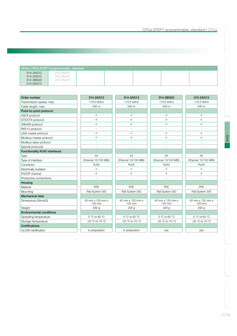
Order number 314-2AG12 314-2AG13 314-2BG03 315-2AG12Transmission speed, max. 115.5 kbit/s 115.5 kbit/s 115.5 kbit/s 115.5 kbit/s
Cable length, max. 500 m 500 m 500 m 500 m
Point-to-point protocolASCII protocolSTX/ETX protocol3964(R) protocolRK512 protocol - - - -
USS master protocolModbus master protocolModbus slave protocol - - - -
Special protocols - - - -
Functionality RJ45 interfacesType X4 X4 X4 X4
Type of interface Ethernet 10/100 MBit Ethernet 10/100 MBit Ethernet 10/100 MBit Ethernet 10/100 MBit
Connector RJ45 RJ45 RJ45 RJ45
Electrically isolatedPG/OP channelProductive connections - - - -
HousingMaterial PPE PPE PPE PPE
Mounting Rail System 300 Rail System 300 Rail System 300 Rail System 300
Mechanical dataDimensions (WxHxD) 40 mm x 125 mm x
120 mm40 mm x 125 mm x
120 mm40 mm x 125 mm x
120 mm40 mm x 125 mm x
120 mm
Weight 290 g 290 g 235 g 290 g
Environmental conditionsOperating temperature 0 °C to 60 °C 0 °C to 60 °C 0 °C to 60 °C 0 °C to 60 °C
Storage temperature -25 °C to 70 °C -25 °C to 70 °C -25 °C to 70 °C -25 °C to 70 °C
CertificationsUL508 certification in preparation in preparation yes yes
376
SLI
O10
0V20
0V30
0S50
0SH
MI
Sof
twar
eA
cces
sorie
sA
ppen
dix
CPUs | CPUs STEP7 programmable, standard
CPUs | CPUs STEP7 programmable, standard314-2AG12314-2AG13314-2BG03315-2AG12
315-2AG13317-2AJ12317-2AJ13
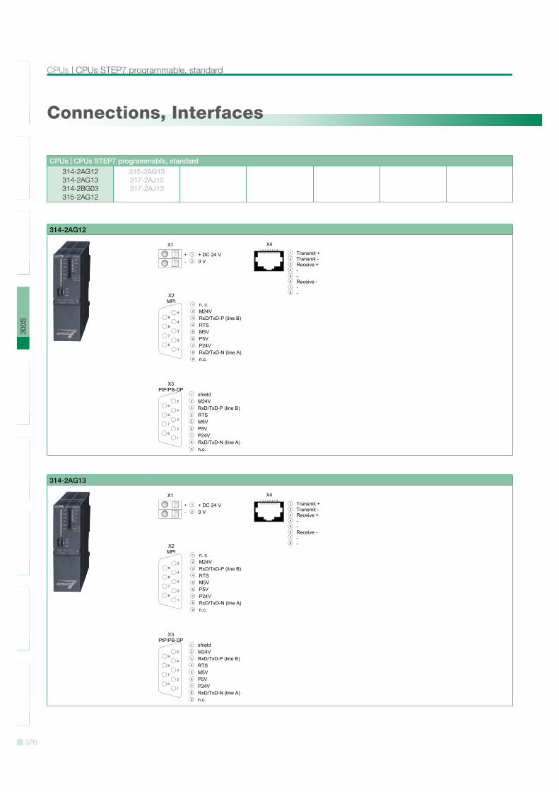
Connections, Interfaces
314-2AG12
314-2AG13
377
SLI
O10
0V20
0V30
0S50
0SH
MI
Sof
twar
eA
cces
sorie
sA
ppen
dix
CPUs STEP7 programmable, standard | CPUs
CPUs | CPUs STEP7 programmable, standard314-2AG12314-2AG13314-2BG03315-2AG12
315-2AG13317-2AJ12317-2AJ13
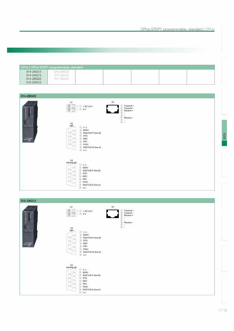
314-2BG03
315-2AG12
378
SLI
O10
0V20
0V30
0S50
0SH
MI
Sof
twar
eA
cces
sorie
sA
ppen
dix
CPUs | CPUs STEP7 programmable, standard
CPUs | CPUs STEP7 programmable, standard314-2AG12314-2AG13314-2BG03315-2AG12
315-2AG13317-2AJ12317-2AJ13
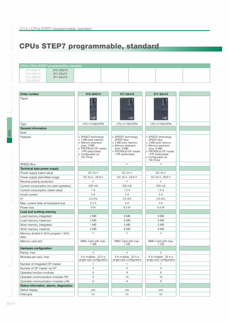
CPUs STEP7 programmable, standard
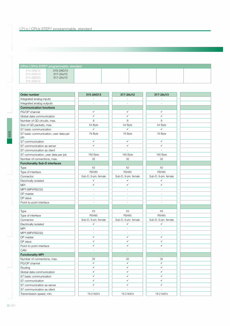
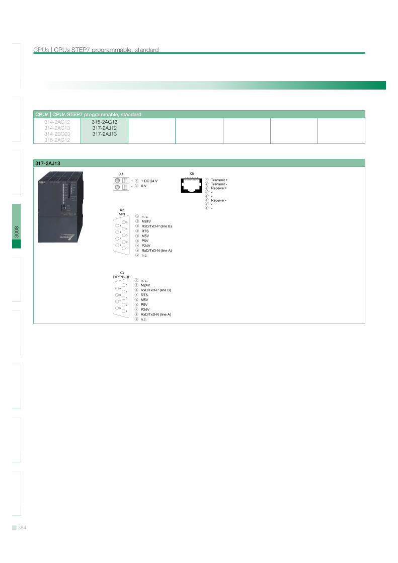
Order number 315-2AG13 317-2AJ12 317-2AJ13Figure
Type CPU 315SB/DPM CPU 317SE/DPM CPU 317SE/DPM
General informationNote - - -
Features SPEED7 technology 1 MB work memory Memory extension (max. 2 MB)
PROFIBUS-DP master / PtP (switchable)
Configurable via TIA-Portal
SPEED7 technology, SPEED-Bus
2 MB work memory Memory extension (max. 8 MB)
PROFIBUS-DP master / PtP (switchable)
SPEED7 technology, SPEED-Bus
2 MB work memory Memory extension (max. 8 MB)
PROFIBUS-DP master / PtP (switchable)
Configurable via TIA-Portal
SPEED-Bus -
Technical data power supplyPower supply (rated value) DC 24 V DC 24 V DC 24 V
Power supply (permitted range) DC 20.4...28.8 V DC 20.4...28.8 V DC 20.4...28.8 V
Reverse polarity protectionCurrent consumption (no-load operation) 200 mA 200 mA 200 mA
Current consumption (rated value) 1 A 1.5 A 1.5 A
Inrush current 5 A 5 A 5 A
I!t 0.5 A!s 0.5 A!s 0.5 A!s
Max. current drain at backplane bus 2.5 A 4 A 4 A
Power loss 6 W 6.5 W 6.5 W
Load and working memoryLoad memory, integrated 2 MB 8 MB 8 MB
Load memory, maximum 2 MB 8 MB 8 MB
Work memory, integrated 1 MB 2 MB 2 MB
Work memory, maximal 2 MB 8 MB 8 MB
Memory divided in 50% program / 50% dataMemory card slot MMC-Card with max.
1 GBMMC-Card with max.
1 GBMMC-Card with max.
1 GB
Hardware configurationRacks, max. 4 4 4
Modules per rack, max. 8 in multiple-, 32 in a single-rack configuration
8 in multiple-, 32 in a single-rack configuration
8 in multiple-, 32 in a single-rack configuration
Number of integrated DP master 1 1 1
Number of DP master via CP 4 4 4
Operable function modules 8 8 8
Operable communication modules PtP 8 16 16
Operable communication modules LAN 8 8 8
Status information, alarms, diagnosticsStatus display yes yes yes
Interrupts no no no
379
SLI
O10
0V20
0V30
0S50
0SH
MI
Sof
twar
eA
cces
sorie
sA
ppen
dix
CPUs STEP7 programmable, standard | CPUs
CPUs | CPUs STEP7 programmable, standard314-2AG12314-2AG13314-2BG03315-2AG12
315-2AG13317-2AJ12317-2AJ13
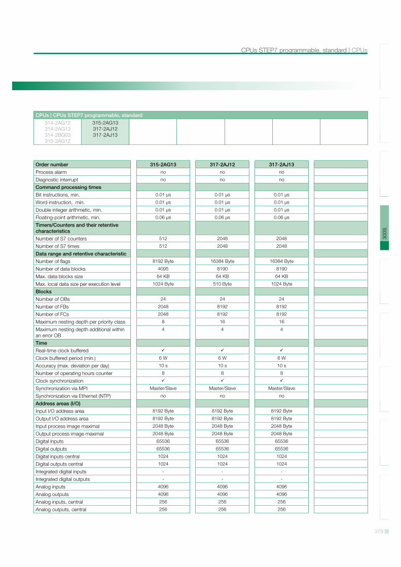
Order number 315-2AG13 317-2AJ12 317-2AJ13Process alarm no no no
Diagnostic interrupt no no no
Command processing timesBit instructions, min. 0.01 µs 0.01 µs 0.01 µs
Word instruction, min. 0.01 µs 0.01 µs 0.01 µs
Double integer arithmetic, min. 0.01 µs 0.01 µs 0.01 µs
Floating-point arithmetic, min. 0.06 µs 0.06 µs 0.06 µs
Timers/Counters and their retentive characteristicsNumber of S7 counters 512 2048 2048
Number of S7 times 512 2048 2048
Data range and retentive characteristicNumber of flags 8192 Byte 16384 Byte 16384 Byte
Number of data blocks 4095 8190 8190
Max. data blocks size 64 KB 64 KB 64 KB
Max. local data size per execution level 1024 Byte 510 Byte 1024 Byte
BlocksNumber of OBs 24 24 24
Number of FBs 2048 8192 8192
Number of FCs 2048 8192 8192
Maximum nesting depth per priority class 8 16 16
Maximum nesting depth additional within an error OB
4 4 4
TimeReal-time clock bufferedClock buffered period (min.) 6 W 6 W 6 W
Accuracy (max. deviation per day) 10 s 10 s 10 s
Number of operating hours counter 8 8 8
Clock synchronizationSynchronization via MPI Master/Slave Master/Slave Master/Slave
Synchronization via Ethernet (NTP) no no no
Address areas (I/O)Input I/O address area 8192 Byte 8192 Byte 8192 Byte
Output I/O address area 8192 Byte 8192 Byte 8192 Byte
Input process image maximal 2048 Byte 2048 Byte 2048 Byte
Output process image maximal 2048 Byte 2048 Byte 2048 Byte
Digital inputs 65536 65536 65536
Digital outputs 65536 65536 65536
Digital inputs central 1024 1024 1024
Digital outputs central 1024 1024 1024
Integrated digital inputs - - -
Integrated digital outputs - - -
Analog inputs 4096 4096 4096
Analog outputs 4096 4096 4096
Analog inputs, central 256 256 256
Analog outputs, central 256 256 256
380
SLI
O10
0V20
0V30
0S50
0SH
MI
Sof
twar
eA
cces
sorie
sA
ppen
dix
CPUs | CPUs STEP7 programmable, standard
CPUs | CPUs STEP7 programmable, standard314-2AG12314-2AG13314-2BG03315-2AG12
315-2AG13317-2AJ12317-2AJ13
Order number 315-2AG13 317-2AJ12 317-2AJ13Integrated analog inputs - - -
Integrated analog outputs - - -
Communication functionsPG/OP channelGlobal data communicationNumber of GD circuits, max. 8 8 8
Size of GD packets, max. 54 Byte 54 Byte 54 Byte
S7 basic communicationS7 basic communication, user data per job
76 Byte 76 Byte 76 Byte
S7 communicationS7 communication as serverS7 communication as client - - -
S7 communication, user data per job 160 Byte 160 Byte 160 Byte
Number of connections, max. 32 32 32
Functionality Sub-D interfacesType X2 X2 X2
Type of interface RS485 RS485 RS485
Connector Sub-D, 9-pin, female Sub-D, 9-pin, female Sub-D, 9-pin, female
Electrically isolatedMPIMP!I (MPI/RS232) - - -
DP master - - -
DP slave - - -
Point-to-point interface - - -
Type X3 X3 X3
Type of interface RS485 RS485 RS485
Connector Sub-D, 9-pin, female Sub-D, 9-pin, female Sub-D, 9-pin, female
Electrically isolatedMPI - - -
MP!I (MPI/RS232) - - -
DP masterDP slavePoint-to-point interfaceCAN - - -
Functionality MPINumber of connections, max. 32 32 32
PG/OP channelRoutingGlobal data communicationS7 basic communicationS7 communicationS7 communication as serverS7 communication as client - - -
Transmission speed, min. 19.2 kbit/s 19.2 kbit/s 19.2 kbit/s
381
SLI
O10
0V20
0V30
0S50
0SH
MI
Sof
twar
eA
cces
sorie
sA
ppen
dix
CPUs STEP7 programmable, standard | CPUs
CPUs | CPUs STEP7 programmable, standard314-2AG12314-2AG13314-2BG03315-2AG12
315-2AG13317-2AJ12317-2AJ13
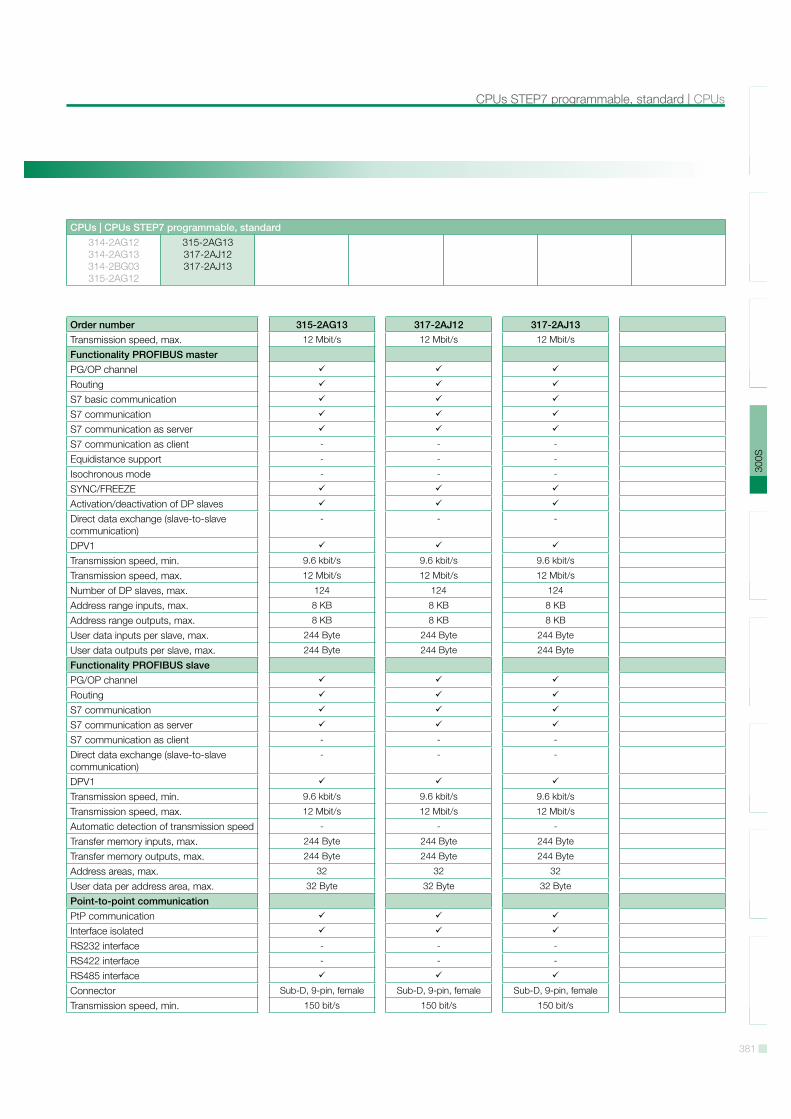
Order number 315-2AG13 317-2AJ12 317-2AJ13Transmission speed, max. 12 Mbit/s 12 Mbit/s 12 Mbit/s
Functionality PROFIBUS masterPG/OP channelRoutingS7 basic communicationS7 communicationS7 communication as serverS7 communication as client - - -
Equidistance support - - -
Isochronous mode - - -
SYNC/FREEZEActivation/deactivation of DP slavesDirect data exchange (slave-to-slave communication)
- - -
DPV1Transmission speed, min. 9.6 kbit/s 9.6 kbit/s 9.6 kbit/s
Transmission speed, max. 12 Mbit/s 12 Mbit/s 12 Mbit/s
Number of DP slaves, max. 124 124 124
Address range inputs, max. 8 KB 8 KB 8 KB
Address range outputs, max. 8 KB 8 KB 8 KB
User data inputs per slave, max. 244 Byte 244 Byte 244 Byte
User data outputs per slave, max. 244 Byte 244 Byte 244 Byte
Functionality PROFIBUS slavePG/OP channelRoutingS7 communicationS7 communication as serverS7 communication as client - - -
Direct data exchange (slave-to-slave communication)
- - -
DPV1Transmission speed, min. 9.6 kbit/s 9.6 kbit/s 9.6 kbit/s
Transmission speed, max. 12 Mbit/s 12 Mbit/s 12 Mbit/s
Automatic detection of transmission speed - - -
Transfer memory inputs, max. 244 Byte 244 Byte 244 Byte
Transfer memory outputs, max. 244 Byte 244 Byte 244 Byte
Address areas, max. 32 32 32
User data per address area, max. 32 Byte 32 Byte 32 Byte
Point-to-point communicationPtP communicationInterface isolatedRS232 interface - - -
RS422 interface - - -
RS485 interfaceConnector Sub-D, 9-pin, female Sub-D, 9-pin, female Sub-D, 9-pin, female
Transmission speed, min. 150 bit/s 150 bit/s 150 bit/s
382
SLI
O10
0V20
0V30
0S50
0SH
MI
Sof
twar
eA
cces
sorie
sA
ppen
dix
CPUs | CPUs STEP7 programmable, standard
CPUs | CPUs STEP7 programmable, standard314-2AG12314-2AG13314-2BG03315-2AG12
315-2AG13317-2AJ12317-2AJ13
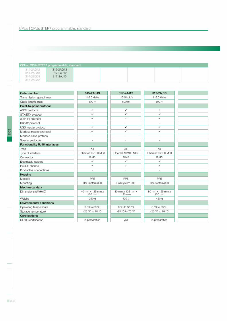
Order number 315-2AG13 317-2AJ12 317-2AJ13Transmission speed, max. 115.5 kbit/s 115.5 kbit/s 115.5 kbit/s
Cable length, max. 500 m 500 m 500 m
Point-to-point protocolASCII protocolSTX/ETX protocol3964(R) protocolRK512 protocol - - -
USS master protocolModbus master protocolModbus slave protocol - - -
Special protocols - - -
Functionality RJ45 interfacesType X4 X5 X5
Type of interface Ethernet 10/100 MBit Ethernet 10/100 MBit Ethernet 10/100 MBit
Connector RJ45 RJ45 RJ45
Electrically isolatedPG/OP channelProductive connections - - -
HousingMaterial PPE PPE PPE
Mounting Rail System 300 Rail System 300 Rail System 300
Mechanical dataDimensions (WxHxD) 40 mm x 125 mm x
120 mm80 mm x 125 mm x
120 mm80 mm x 125 mm x
120 mm
Weight 290 g 420 g 420 g
Environmental conditionsOperating temperature 0 °C to 60 °C 0 °C to 60 °C 0 °C to 60 °C
Storage temperature -25 °C to 70 °C -25 °C to 70 °C -25 °C to 70 °C
CertificationsUL508 certification in preparation yes in preparation
383
SLI
O10
0V20
0V30
0S50
0SH
MI
Sof
twar
eA
cces
sorie
sA
ppen
dix
CPUs STEP7 programmable, standard | CPUs
CPUs | CPUs STEP7 programmable, standard314-2AG12314-2AG13314-2BG03315-2AG12
315-2AG13317-2AJ12317-2AJ13
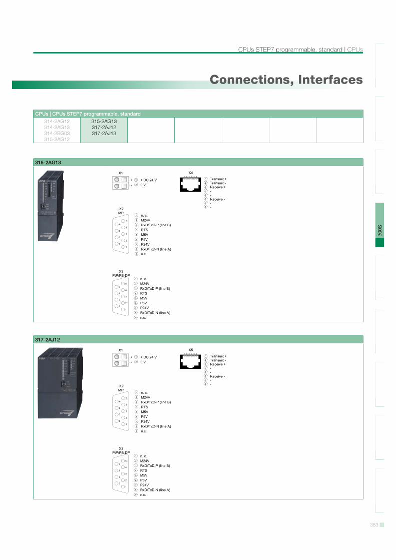
Connections, Interfaces
315-2AG13
317-2AJ12
384
SLI
O10
0V20
0V30
0S50
0SH
MI
Sof
twar
eA
cces
sorie
sA
ppen
dix
CPUs | CPUs STEP7 programmable, standard
CPUs | CPUs STEP7 programmable, standard314-2AG12314-2AG13314-2BG03315-2AG12
315-2AG13317-2AJ12317-2AJ13
317-2AJ13
385
SLI
O10
0V20
0V30
0S50
0SH
MI
Sof
twar
eA
cces
sorie
sA
ppen
dix
CPUs STEP7 programmable, NET-CPUs | CPUs
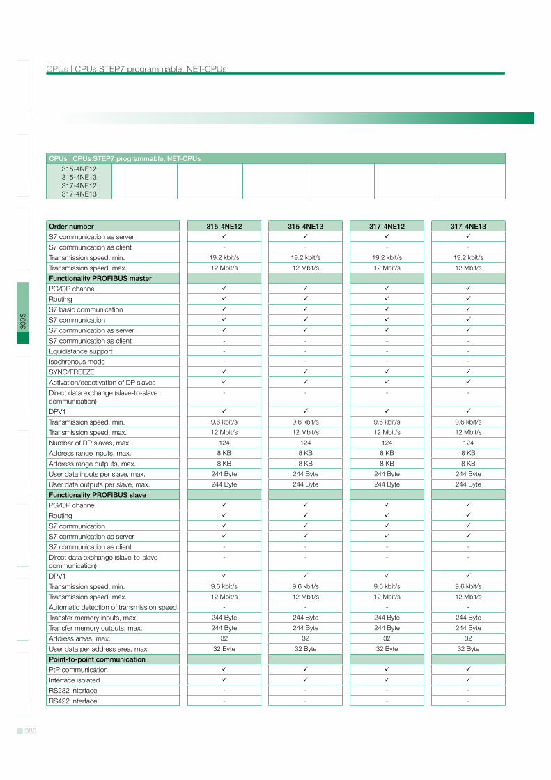
CPUs | CPUs STEP7 programmable, NET-CPUs315-4NE12315-4NE13317-4NE12317-4NE13
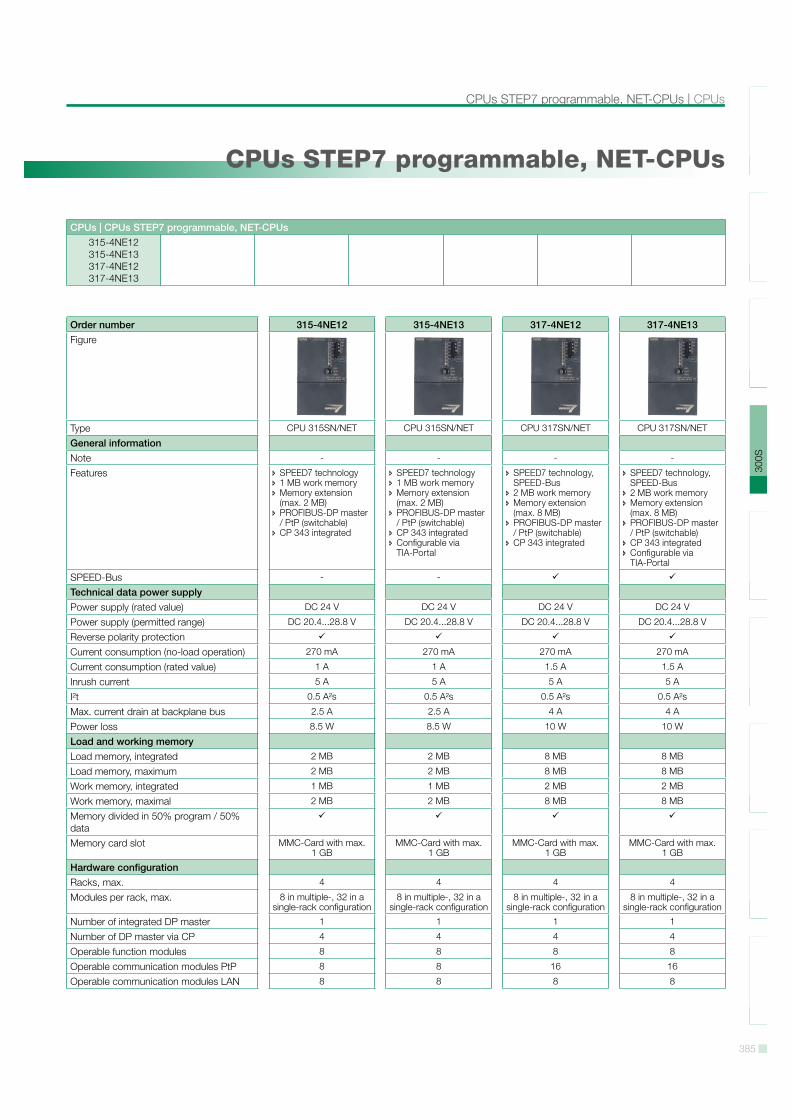
CPUs STEP7 programmable, NET-CPUs
Order number 315-4NE12 315-4NE13 317-4NE12 317-4NE13Figure
Type CPU 315SN/NET CPU 315SN/NET CPU 317SN/NET CPU 317SN/NET
General informationNote - - - -
Features SPEED7 technology 1 MB work memory Memory extension (max. 2 MB)
PROFIBUS-DP master / PtP (switchable)
CP 343 integrated
SPEED7 technology 1 MB work memory Memory extension (max. 2 MB)
PROFIBUS-DP master / PtP (switchable)
CP 343 integrated Configurable via TIA-Portal
SPEED7 technology, SPEED-Bus
2 MB work memory Memory extension (max. 8 MB)
PROFIBUS-DP master / PtP (switchable)
CP 343 integrated
SPEED7 technology, SPEED-Bus
2 MB work memory Memory extension (max. 8 MB)
PROFIBUS-DP master / PtP (switchable)
CP 343 integrated Configurable via TIA-Portal
SPEED-Bus - -
Technical data power supplyPower supply (rated value) DC 24 V DC 24 V DC 24 V DC 24 V
Power supply (permitted range) DC 20.4...28.8 V DC 20.4...28.8 V DC 20.4...28.8 V DC 20.4...28.8 V
Reverse polarity protectionCurrent consumption (no-load operation) 270 mA 270 mA 270 mA 270 mA
Current consumption (rated value) 1 A 1 A 1.5 A 1.5 A
Inrush current 5 A 5 A 5 A 5 A
I!t 0.5 A!s 0.5 A!s 0.5 A!s 0.5 A!s
Max. current drain at backplane bus 2.5 A 2.5 A 4 A 4 A
Power loss 8.5 W 8.5 W 10 W 10 W
Load and working memoryLoad memory, integrated 2 MB 2 MB 8 MB 8 MB
Load memory, maximum 2 MB 2 MB 8 MB 8 MB
Work memory, integrated 1 MB 1 MB 2 MB 2 MB
Work memory, maximal 2 MB 2 MB 8 MB 8 MB
Memory divided in 50% program / 50% dataMemory card slot MMC-Card with max.
1 GBMMC-Card with max.
1 GBMMC-Card with max.
1 GBMMC-Card with max.
1 GB
Hardware configurationRacks, max. 4 4 4 4
Modules per rack, max. 8 in multiple-, 32 in a single-rack configuration
8 in multiple-, 32 in a single-rack configuration
8 in multiple-, 32 in a single-rack configuration
8 in multiple-, 32 in a single-rack configuration
Number of integrated DP master 1 1 1 1
Number of DP master via CP 4 4 4 4
Operable function modules 8 8 8 8
Operable communication modules PtP 8 8 16 16
Operable communication modules LAN 8 8 8 8
386
SLI
O10
0V20
0V30
0S50
0SH
MI
Sof
twar
eA
cces
sorie
sA
ppen
dix
CPUs | CPUs STEP7 programmable, NET-CPUs
CPUs | CPUs STEP7 programmable, NET-CPUs315-4NE12315-4NE13317-4NE12317-4NE13
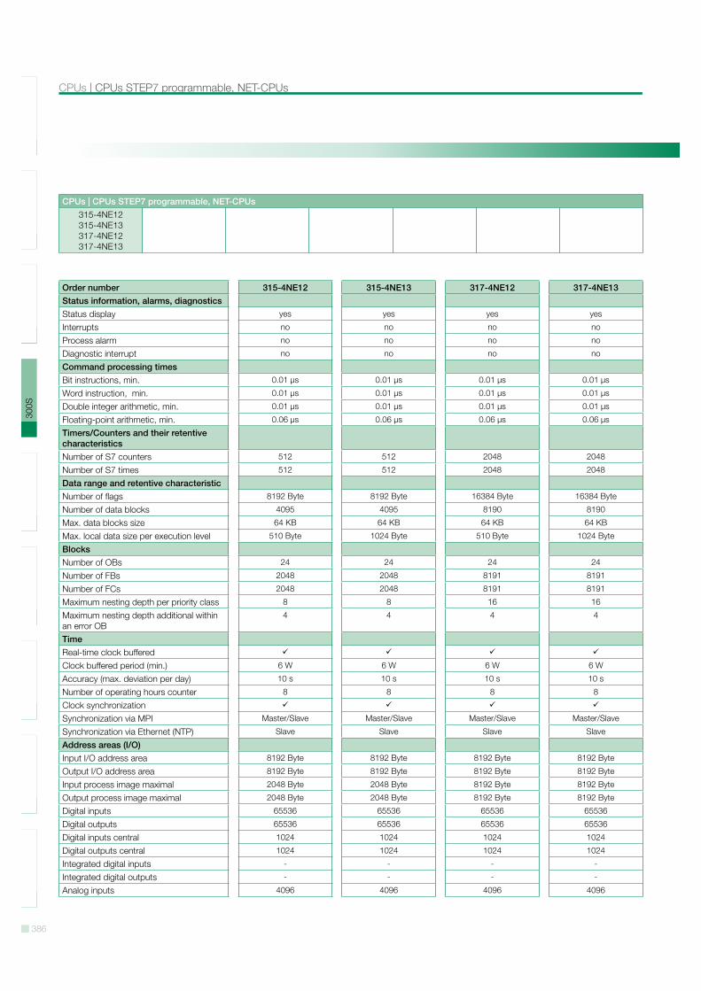
Order number 315-4NE12 315-4NE13 317-4NE12 317-4NE13Status information, alarms, diagnosticsStatus display yes yes yes yes
Interrupts no no no no
Process alarm no no no no
Diagnostic interrupt no no no no
Command processing timesBit instructions, min. 0.01 µs 0.01 µs 0.01 µs 0.01 µs
Word instruction, min. 0.01 µs 0.01 µs 0.01 µs 0.01 µs
Double integer arithmetic, min. 0.01 µs 0.01 µs 0.01 µs 0.01 µs
Floating-point arithmetic, min. 0.06 µs 0.06 µs 0.06 µs 0.06 µs
Timers/Counters and their retentive characteristicsNumber of S7 counters 512 512 2048 2048
Number of S7 times 512 512 2048 2048
Data range and retentive characteristicNumber of flags 8192 Byte 8192 Byte 16384 Byte 16384 Byte
Number of data blocks 4095 4095 8190 8190
Max. data blocks size 64 KB 64 KB 64 KB 64 KB
Max. local data size per execution level 510 Byte 1024 Byte 510 Byte 1024 Byte
BlocksNumber of OBs 24 24 24 24
Number of FBs 2048 2048 8191 8191
Number of FCs 2048 2048 8191 8191
Maximum nesting depth per priority class 8 8 16 16
Maximum nesting depth additional within an error OB
4 4 4 4
TimeReal-time clock bufferedClock buffered period (min.) 6 W 6 W 6 W 6 W
Accuracy (max. deviation per day) 10 s 10 s 10 s 10 s
Number of operating hours counter 8 8 8 8
Clock synchronizationSynchronization via MPI Master/Slave Master/Slave Master/Slave Master/Slave
Synchronization via Ethernet (NTP) Slave Slave Slave Slave
Address areas (I/O)Input I/O address area 8192 Byte 8192 Byte 8192 Byte 8192 Byte
Output I/O address area 8192 Byte 8192 Byte 8192 Byte 8192 Byte
Input process image maximal 2048 Byte 2048 Byte 8192 Byte 8192 Byte
Output process image maximal 2048 Byte 2048 Byte 8192 Byte 8192 Byte
Digital inputs 65536 65536 65536 65536
Digital outputs 65536 65536 65536 65536
Digital inputs central 1024 1024 1024 1024
Digital outputs central 1024 1024 1024 1024
Integrated digital inputs - - - -
Integrated digital outputs - - - -
Analog inputs 4096 4096 4096 4096
387
SLI
O10
0V20
0V30
0S50
0SH
MI
Sof
twar
eA
cces
sorie
sA
ppen
dix
CPUs STEP7 programmable, NET-CPUs | CPUs
CPUs | CPUs STEP7 programmable, NET-CPUs315-4NE12315-4NE13317-4NE12317-4NE13
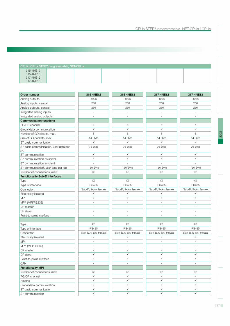
Order number 315-4NE12 315-4NE13 317-4NE12 317-4NE13Analog outputs 4096 4096 4096 4096
Analog inputs, central 256 256 256 256
Analog outputs, central 256 256 256 256
Integrated analog inputs - - - -
Integrated analog outputs - - - -
Communication functionsPG/OP channelGlobal data communicationNumber of GD circuits, max. 8 8 8 8
Size of GD packets, max. 54 Byte 54 Byte 54 Byte 54 Byte
S7 basic communicationS7 basic communication, user data per job
76 Byte 76 Byte 76 Byte 76 Byte
S7 communicationS7 communication as serverS7 communication as client - - - -
S7 communication, user data per job 160 Byte 160 Byte 160 Byte 160 Byte
Number of connections, max. 32 32 32 32
Functionality Sub-D interfacesType X2 X2 X2 X2
Type of interface RS485 RS485 RS485 RS485
Connector Sub-D, 9-pin, female Sub-D, 9-pin, female Sub-D, 9-pin, female Sub-D, 9-pin, female
Electrically isolatedMPIMP!I (MPI/RS232) - - - -
DP master - - - -
DP slave - - - -
Point-to-point interface - - - -
Type X3 X3 X3 X3
Type of interface RS485 RS485 RS485 RS485
Connector Sub-D, 9-pin, female Sub-D, 9-pin, female Sub-D, 9-pin, female Sub-D, 9-pin, female
Electrically isolatedMPI - - - -
MP!I (MPI/RS232) - - - -
DP masterDP slavePoint-to-point interfaceCAN - - - -
Functionality MPINumber of connections, max. 32 32 32 32
PG/OP channelRoutingGlobal data communicationS7 basic communicationS7 communication
388
SLI
O10
0V20
0V30
0S50
0SH
MI
Sof
twar
eA
cces
sorie
sA
ppen
dix
CPUs | CPUs STEP7 programmable, NET-CPUs
CPUs | CPUs STEP7 programmable, NET-CPUs315-4NE12315-4NE13317-4NE12317-4NE13
Order number 315-4NE12 315-4NE13 317-4NE12 317-4NE13S7 communication as serverS7 communication as client - - - -
Transmission speed, min. 19.2 kbit/s 19.2 kbit/s 19.2 kbit/s 19.2 kbit/s
Transmission speed, max. 12 Mbit/s 12 Mbit/s 12 Mbit/s 12 Mbit/s
Functionality PROFIBUS masterPG/OP channelRoutingS7 basic communicationS7 communicationS7 communication as serverS7 communication as client - - - -
Equidistance support - - - -
Isochronous mode - - - -
SYNC/FREEZEActivation/deactivation of DP slavesDirect data exchange (slave-to-slave communication)
- - - -
DPV1Transmission speed, min. 9.6 kbit/s 9.6 kbit/s 9.6 kbit/s 9.6 kbit/s
Transmission speed, max. 12 Mbit/s 12 Mbit/s 12 Mbit/s 12 Mbit/s
Number of DP slaves, max. 124 124 124 124
Address range inputs, max. 8 KB 8 KB 8 KB 8 KB
Address range outputs, max. 8 KB 8 KB 8 KB 8 KB
User data inputs per slave, max. 244 Byte 244 Byte 244 Byte 244 Byte
User data outputs per slave, max. 244 Byte 244 Byte 244 Byte 244 Byte
Functionality PROFIBUS slavePG/OP channelRoutingS7 communicationS7 communication as serverS7 communication as client - - - -
Direct data exchange (slave-to-slave communication)
- - - -
DPV1Transmission speed, min. 9.6 kbit/s 9.6 kbit/s 9.6 kbit/s 9.6 kbit/s
Transmission speed, max. 12 Mbit/s 12 Mbit/s 12 Mbit/s 12 Mbit/s
Automatic detection of transmission speed - - - -
Transfer memory inputs, max. 244 Byte 244 Byte 244 Byte 244 Byte
Transfer memory outputs, max. 244 Byte 244 Byte 244 Byte 244 Byte
Address areas, max. 32 32 32 32
User data per address area, max. 32 Byte 32 Byte 32 Byte 32 Byte
Point-to-point communicationPtP communicationInterface isolatedRS232 interface - - - -
RS422 interface - - - -
389
SLI
O10
0V20
0V30
0S50
0SH
MI
Sof
twar
eA
cces
sorie
sA
ppen
dix
CPUs STEP7 programmable, NET-CPUs | CPUs
CPUs | CPUs STEP7 programmable, NET-CPUs315-4NE12315-4NE13317-4NE12317-4NE13
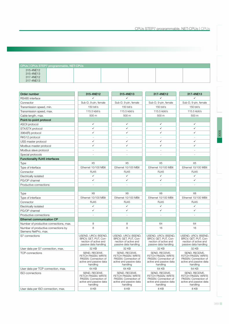
Order number 315-4NE12 315-4NE13 317-4NE12 317-4NE13RS485 interfaceConnector Sub-D, 9-pin, female Sub-D, 9-pin, female Sub-D, 9-pin, female Sub-D, 9-pin, female
Transmission speed, min. 150 bit/s 150 bit/s 150 bit/s 150 bit/s
Transmission speed, max. 115.5 kbit/s 115.5 kbit/s 115.5 kbit/s 115.5 kbit/s
Cable length, max. 500 m 500 m 500 m 500 m
Point-to-point protocolASCII protocolSTX/ETX protocol3964(R) protocolRK512 protocol - - - -
USS master protocolModbus master protocolModbus slave protocol - - - -
Special protocols - - - -
Functionality RJ45 interfacesType X5 X5 X5 X5
Type of interface Ethernet 10/100 MBit Ethernet 10/100 MBit Ethernet 10/100 MBit Ethernet 10/100 MBit
Connector RJ45 RJ45 RJ45 RJ45
Electrically isolatedPG/OP channelProductive connections - - - -
Type X8 X8 X8 X8
Type of interface Ethernet 10/100 MBit Ethernet 10/100 MBit Ethernet 10/100 MBit Ethernet 10/100 MBit
Connector RJ45 RJ45 RJ45 RJ45
Electrically isolatedPG/OP channelProductive connections - - - -
Ethernet communication CPNumber of productive connections, max. 8 8 64 64
Number of productive connections by Siemens NetPro, max.
8 8 16 16
S7 connections USEND, URCV, BSEND, BRCV, GET, PUT, Con-nection of active and passive data handling
USEND, URCV, BSEND, BRCV, GET, PUT, Con-nection of active and passive data handling
USEND, URCV, BSEND, BRCV, GET, PUT, Con-nection of active and passive data handling
USEND, URCV, BSEND, BRCV, GET, PUT, Con-nection of active and passive data handling
User data per S7 connection, max. 32 KB 32 KB 32 KB 32 KB
TCP-connections SEND, RECEIVE, FETCH PASSIV, WRITE PASSIV, Connection of active and passive data
handling
SEND, RECEIVE, FETCH PASSIV, WRITE PASSIV, Connection of active and passive data
handling
SEND, RECEIVE, FETCH PASSIV, WRITE PASSIV, Connection of active and passive data
handling
SEND, RECEIVE, FETCH PASSIV, WRITE PASSIV, Connection of active and passive data
handling
User data per TCP connection, max. 64 KB 64 KB 64 KB 64 KB
ISO-connections SEND, RECEIVE, FETCH PASSIV, WRITE PASSIV, Connection of active and passive data
handling
SEND, RECEIVE, FETCH PASSIV, WRITE PASSIV, Connection of active and passive data
handling
SEND, RECEIVE, FETCH PASSIV, WRITE PASSIV, Connection of active and passive data
handling
SEND, RECEIVE, FETCH PASSIV, WRITE PASSIV, Connection of active and passive data
handling
User data per ISO connection, max. 8 KB 8 KB 8 KB 8 KB
390
SLI
O10
0V20
0V30
0S50
0SH
MI
Sof
twar
eA
cces
sorie
sA
ppen
dix
CPUs | CPUs STEP7 programmable, NET-CPUs
CPUs | CPUs STEP7 programmable, NET-CPUs315-4NE12315-4NE13317-4NE12317-4NE13
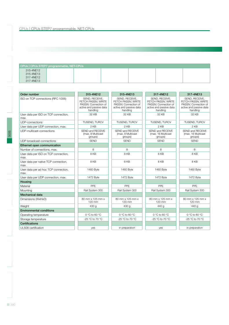
Order number 315-4NE12 315-4NE13 317-4NE12 317-4NE13ISO on TCP connections (RFC 1006) SEND, RECEIVE,
FETCH PASSIV, WRITE PASSIV, Connection of active and passive data
handling
SEND, RECEIVE, FETCH PASSIV, WRITE PASSIV, Connection of active and passive data
handling
SEND, RECEIVE, FETCH PASSIV, WRITE PASSIV, Connection of active and passive data
handling
SEND, RECEIVE, FETCH PASSIV, WRITE PASSIV, Connection of active and passive data
handling
User data per ISO on TCP connection, max.
32 KB 32 KB 32 KB 32 KB
UDP-connections TUSEND, TURCV TUSEND, TURCV TUSEND, TURCV TUSEND, TURCV
User data per UDP connection, max. 2 KB 2 KB 2 KB 2 KB
UDP-multicast-connections SEND and RECEIVE (max. 8 Multicast
groups)
SEND and RECEIVE (max. 8 Multicast
groups)
SEND and RECEIVE (max. 16 Multicast
groups)
SEND and RECEIVE (max. 16 Multicast
groups)
UDP-broadcast-connections SEND SEND SEND SEND
Ethernet open communicationNumber of connections, max. 8 8 8 8
User data per ISO on TCP connection, max.
8 KB 8 KB 8 KB 8 KB
User data per native TCP connection, max.
8 KB 8 KB 8 KB 8 KB
User data per ad hoc TCP connection, max.
1460 Byte 1460 Byte 1460 Byte 1460 Byte
User data per UDP connection, max. 1472 Byte 1472 Byte 1472 Byte 1472 Byte
HousingMaterial PPE PPE PPE PPE
Mounting Rail System 300 Rail System 300 Rail System 300 Rail System 300
Mechanical dataDimensions (WxHxD) 80 mm x 125 mm x
120 mm80 mm x 125 mm x
120 mm80 mm x 125 mm x
120 mm80 mm x 125 mm x
120 mm
Weight 430 g 430 g 440 g 440 g
Environmental conditionsOperating temperature 0 °C to 60 °C 0 °C to 60 °C 0 °C to 60 °C 0 °C to 60 °C
Storage temperature -25 °C to 70 °C -25 °C to 70 °C -25 °C to 70 °C -25 °C to 70 °C
CertificationsUL508 certification yes in preparation yes in preparation

391
SLI
O10
0V20
0V30
0S50
0SH
MI
Sof
twar
eA
cces
sorie
sA
ppen
dix
CPUs STEP7 programmable, NET-CPUs | CPUs
CPUs | CPUs STEP7 programmable, NET-CPUs315-4NE12315-4NE13317-4NE12317-4NE13
Connections, Interfaces
315-4NE12
315-4NE13
392
SLI
O10
0V20
0V30
0S50
0SH
MI
Sof
twar
eA
cces
sorie
sA
ppen
dix
CPUs | CPUs STEP7 programmable, NET-CPUs
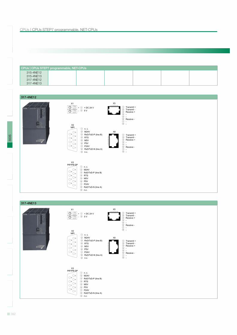
CPUs | CPUs STEP7 programmable, NET-CPUs315-4NE12315-4NE13317-4NE12317-4NE13
317-4NE12
317-4NE13
393
SLI
O10
0V20
0V30
0S50
0SH
MI
Sof
twar
eA
cces
sorie
sA
ppen
dix
CPUs STEP7 programmable, PROFINET | CPUs
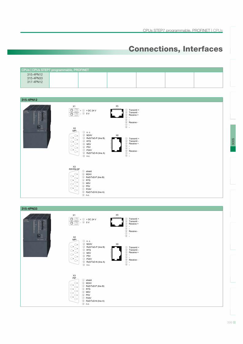
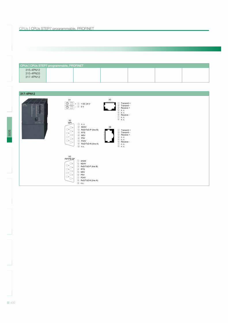
CPUs | CPUs STEP7 programmable, PROFINET315-4PN12315-4PN33317-4PN12
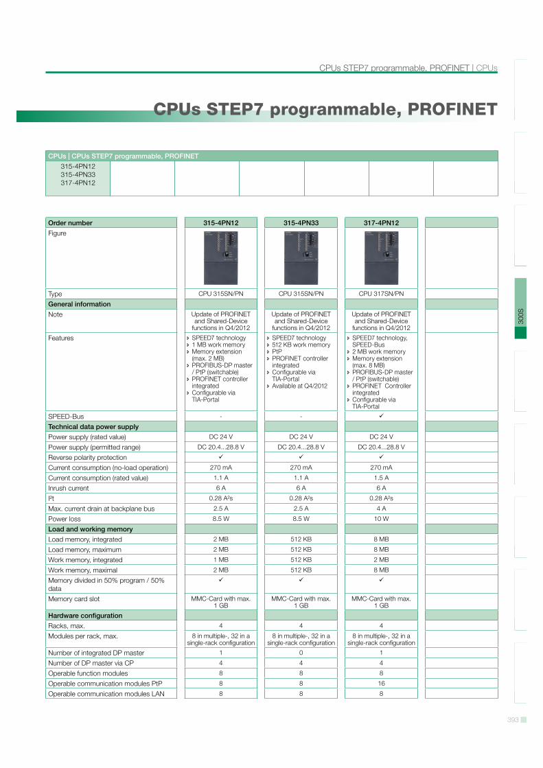
CPUs STEP7 programmable, PROFINET
Order number 315-4PN12 315-4PN33 317-4PN12Figure
Type CPU 315SN/PN CPU 315SN/PN CPU 317SN/PN
General informationNote Update of PROFINET
and Shared-Device functions in Q4/2012
Update of PROFINET and Shared-Device
functions in Q4/2012
Update of PROFINET and Shared-Device
functions in Q4/2012
Features SPEED7 technology 1 MB work memory Memory extension (max. 2 MB)
PROFIBUS-DP master / PtP (switchable)
PROFINET controller integrated
Configurable via TIA-Portal
SPEED7 technology 512 KB work memory PtP PROFINET controller integrated
Configurable via TIA-Portal
Available at Q4/2012
SPEED7 technology, SPEED-Bus
2 MB work memory Memory extension (max. 8 MB)
PROFIBUS-DP master / PtP (switchable)
PROFINET Controller integrated
Configurable via TIA-Portal
SPEED-Bus - -
Technical data power supplyPower supply (rated value) DC 24 V DC 24 V DC 24 V
Power supply (permitted range) DC 20.4...28.8 V DC 20.4...28.8 V DC 20.4...28.8 V
Reverse polarity protectionCurrent consumption (no-load operation) 270 mA 270 mA 270 mA
Current consumption (rated value) 1.1 A 1.1 A 1.5 A
Inrush current 6 A 6 A 6 A
I!t 0.28 A!s 0.28 A!s 0.28 A!s
Max. current drain at backplane bus 2.5 A 2.5 A 4 A
Power loss 8.5 W 8.5 W 10 W
Load and working memoryLoad memory, integrated 2 MB 512 KB 8 MB
Load memory, maximum 2 MB 512 KB 8 MB
Work memory, integrated 1 MB 512 KB 2 MB
Work memory, maximal 2 MB 512 KB 8 MB
Memory divided in 50% program / 50% dataMemory card slot MMC-Card with max.
1 GBMMC-Card with max.
1 GBMMC-Card with max.
1 GB
Hardware configurationRacks, max. 4 4 4
Modules per rack, max. 8 in multiple-, 32 in a single-rack configuration
8 in multiple-, 32 in a single-rack configuration
8 in multiple-, 32 in a single-rack configuration
Number of integrated DP master 1 0 1
Number of DP master via CP 4 4 4
Operable function modules 8 8 8
Operable communication modules PtP 8 8 16
Operable communication modules LAN 8 8 8
394
SLI
O10
0V20
0V30
0S50
0SH
MI
Sof
twar
eA
cces
sorie
sA
ppen
dix
CPUs | CPUs STEP7 programmable, PROFINET
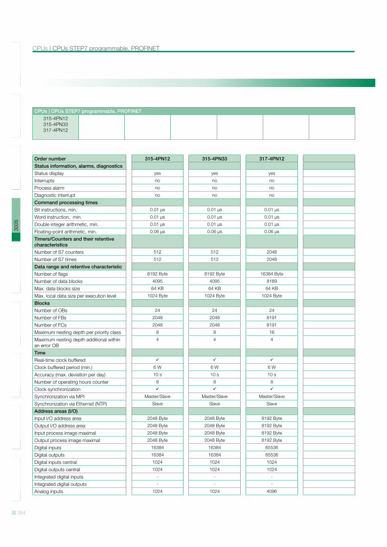
CPUs | CPUs STEP7 programmable, PROFINET315-4PN12315-4PN33317-4PN12
Order number 315-4PN12 315-4PN33 317-4PN12Status information, alarms, diagnosticsStatus display yes yes yes
Interrupts no no no
Process alarm no no no
Diagnostic interrupt no no no
Command processing timesBit instructions, min. 0.01 µs 0.01 µs 0.01 µs
Word instruction, min. 0.01 µs 0.01 µs 0.01 µs
Double integer arithmetic, min. 0.01 µs 0.01 µs 0.01 µs
Floating-point arithmetic, min. 0.06 µs 0.06 µs 0.06 µs
Timers/Counters and their retentive characteristicsNumber of S7 counters 512 512 2048
Number of S7 times 512 512 2048
Data range and retentive characteristicNumber of flags 8192 Byte 8192 Byte 16384 Byte
Number of data blocks 4095 4095 8189
Max. data blocks size 64 KB 64 KB 64 KB
Max. local data size per execution level 1024 Byte 1024 Byte 1024 Byte
BlocksNumber of OBs 24 24 24
Number of FBs 2048 2048 8191
Number of FCs 2048 2048 8191
Maximum nesting depth per priority class 8 8 16
Maximum nesting depth additional within an error OB
4 4 4
TimeReal-time clock bufferedClock buffered period (min.) 6 W 6 W 6 W
Accuracy (max. deviation per day) 10 s 10 s 10 s
Number of operating hours counter 8 8 8
Clock synchronizationSynchronization via MPI Master/Slave Master/Slave Master/Slave
Synchronization via Ethernet (NTP) Slave Slave Slave
Address areas (I/O)Input I/O address area 2048 Byte 2048 Byte 8192 Byte
Output I/O address area 2048 Byte 2048 Byte 8192 Byte
Input process image maximal 2048 Byte 2048 Byte 8192 Byte
Output process image maximal 2048 Byte 2048 Byte 8192 Byte
Digital inputs 16384 16384 65536
Digital outputs 16384 16384 65536
Digital inputs central 1024 1024 1024
Digital outputs central 1024 1024 1024
Integrated digital inputs - - -
Integrated digital outputs - - -
Analog inputs 1024 1024 4096

395
SLI
O10
0V20
0V30
0S50
0SH
MI
Sof
twar
eA
cces
sorie
sA
ppen
dix
CPUs STEP7 programmable, PROFINET | CPUs
CPUs | CPUs STEP7 programmable, PROFINET315-4PN12315-4PN33317-4PN12
Order number 315-4PN12 315-4PN33 317-4PN12Analog outputs 1024 1024 4096
Analog inputs, central 256 256 256
Analog outputs, central 256 256 256
Integrated analog inputs - - -
Integrated analog outputs - - -
Communication functionsPG/OP channelGlobal data communicationNumber of GD circuits, max. 8 8 8
Size of GD packets, max. 22 Byte 22 Byte 22 Byte
S7 basic communicationS7 basic communication, user data per job
76 Byte 76 Byte 76 Byte
S7 communicationS7 communication as serverS7 communication as client - - -
S7 communication, user data per job 160 Byte 160 Byte 160 Byte
Number of connections, max. 32 32 32
Functionality Sub-D interfacesType X2 X2 X2
Type of interface RS485 RS485 RS485
Connector Sub-D, 9-pin, female Sub-D, 9-pin, female Sub-D, 9-pin, female
Electrically isolatedMPIMP!I (MPI/RS232) - - -
DP master - - -
DP slave - - -
Point-to-point interface - - -
Type X3 X3 X3
Type of interface RS485 RS485 RS485
Connector Sub-D, 9-pin, female Sub-D, 9-pin, female Sub-D, 9-pin, female
Electrically isolatedMPI - - -
MP!I (MPI/RS232) - - -
DP master -
DP slave -
Point-to-point interfaceCAN - - -
Functionality MPINumber of connections, max. 32 32 32
PG/OP channelRoutingGlobal data communicationS7 basic communicationS7 communication
396
SLI
O10
0V20
0V30
0S50
0SH
MI
Sof
twar
eA
cces
sorie
sA
ppen
dix
CPUs | CPUs STEP7 programmable, PROFINET
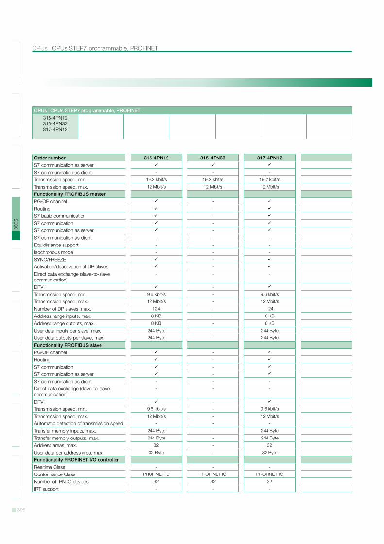
CPUs | CPUs STEP7 programmable, PROFINET315-4PN12315-4PN33317-4PN12
Order number 315-4PN12 315-4PN33 317-4PN12S7 communication as serverS7 communication as client - - -
Transmission speed, min. 19.2 kbit/s 19.2 kbit/s 19.2 kbit/s
Transmission speed, max. 12 Mbit/s 12 Mbit/s 12 Mbit/s
Functionality PROFIBUS masterPG/OP channel -
Routing -
S7 basic communication -
S7 communication -
S7 communication as server -
S7 communication as client - - -
Equidistance support - - -
Isochronous mode - - -
SYNC/FREEZE -
Activation/deactivation of DP slaves -
Direct data exchange (slave-to-slave communication)
- - -
DPV1 -
Transmission speed, min. 9.6 kbit/s - 9.6 kbit/s
Transmission speed, max. 12 Mbit/s - 12 Mbit/s
Number of DP slaves, max. 124 - 124
Address range inputs, max. 8 KB - 8 KB
Address range outputs, max. 8 KB - 8 KB
User data inputs per slave, max. 244 Byte - 244 Byte
User data outputs per slave, max. 244 Byte - 244 Byte
Functionality PROFIBUS slavePG/OP channel -
Routing -
S7 communication -
S7 communication as server -
S7 communication as client - - -
Direct data exchange (slave-to-slave communication)
- - -
DPV1 -
Transmission speed, min. 9.6 kbit/s - 9.6 kbit/s
Transmission speed, max. 12 Mbit/s - 12 Mbit/s
Automatic detection of transmission speed - - -
Transfer memory inputs, max. 244 Byte - 244 Byte
Transfer memory outputs, max. 244 Byte - 244 Byte
Address areas, max. 32 - 32
User data per address area, max. 32 Byte - 32 Byte
Functionality PROFINET I/O controllerRealtime Class - - -
Conformance Class PROFINET IO PROFINET IO PROFINET IO
Number of PN IO devices 32 32 32
IRT support - - -

397
SLI
O10
0V20
0V30
0S50
0SH
MI
Sof
twar
eA
cces
sorie
sA
ppen
dix
CPUs STEP7 programmable, PROFINET | CPUs
CPUs | CPUs STEP7 programmable, PROFINET315-4PN12315-4PN33317-4PN12
Order number 315-4PN12 315-4PN33 317-4PN12Prioritized start-up - - -
Number of PN IO lines 1 1 1
Address range inputs, max. 2 KB 2 KB 4 KB
Address range outputs, max. 2 KB 2 KB 4 KB
Transmiting clock 1 ms 1 ms 1 ms
Update time 1 ms .. 512 ms 1 ms .. 512 ms 1 ms .. 512 ms
Point-to-point communicationPtP communicationInterface isolatedRS232 interface - - -
RS422 interface - - -
RS485 interfaceConnector Sub-D, 9-pin, female Sub-D, 9-pin, female Sub-D, 9-pin, female
Transmission speed, min. 150 bit/s 150 bit/s 150 bit/s
Transmission speed, max. 115.5 kbit/s 115.5 kbit/s 115.5 kbit/s
Cable length, max. 500 m 500 m 500 m
Point-to-point protocolASCII protocolSTX/ETX protocol3964(R) protocolRK512 protocol - - -
USS master protocolModbus master protocolModbus slave protocol - - -
Special protocols - - -
Functionality RJ45 interfacesType X5 X5 X5
Type of interface Ethernet 10/100 MBit Ethernet 10/100 MBit Ethernet 10/100 MBit
Connector RJ45 RJ45 RJ45
Electrically isolatedPG/OP channelProductive connections - - -
Type X8 X8 X8
Type of interface Ethernet 10/100 MBit Ethernet 10/100 MBit Ethernet 10/100 MBit
Connector RJ45 RJ45 RJ45
Electrically isolatedPG/OP channelProductive connections - - -
Ethernet communication CPNumber of productive connections, max. 8 8 24
Number of productive connections by Siemens NetPro, max.
8 8 16
S7 connections USEND, URCV, BSEND, BRCV, GET, PUT, Con-nection of active and passive data handling
USEND, URCV, BSEND, BRCV, GET, PUT, Con-nection of active and passive data handling
USEND, URCV, BSEND, BRCV, GET, PUT, Con-nection of active and passive data handling
398
SLI
O10
0V20
0V30
0S50
0SH
MI
Sof
twar
eA
cces
sorie
sA
ppen
dix
CPUs | CPUs STEP7 programmable, PROFINET
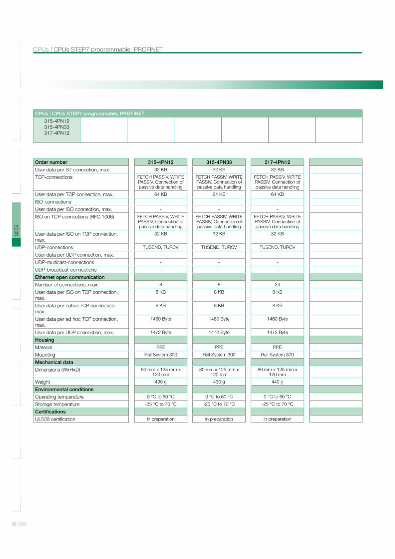
CPUs | CPUs STEP7 programmable, PROFINET315-4PN12315-4PN33317-4PN12
Order number 315-4PN12 315-4PN33 317-4PN12User data per S7 connection, max. 32 KB 32 KB 32 KB
TCP-connections FETCH PASSIV, WRITE PASSIV, Connection of passive data handling
FETCH PASSIV, WRITE PASSIV, Connection of passive data handling
FETCH PASSIV, WRITE PASSIV, Connection of passive data handling
User data per TCP connection, max. 64 KB 64 KB 64 KB
ISO-connections - - -
User data per ISO connection, max. - - -
ISO on TCP connections (RFC 1006) FETCH PASSIV, WRITE PASSIV, Connection of passive data handling
FETCH PASSIV, WRITE PASSIV, Connection of passive data handling
FETCH PASSIV, WRITE PASSIV, Connection of passive data handling
User data per ISO on TCP connection, max.
32 KB 32 KB 32 KB
UDP-connections TUSEND, TURCV TUSEND, TURCV TUSEND, TURCV
User data per UDP connection, max. - - -
UDP-multicast-connections - - -
UDP-broadcast-connections - - -
Ethernet open communicationNumber of connections, max. 8 8 24
User data per ISO on TCP connection, max.
8 KB 8 KB 8 KB
User data per native TCP connection, max.
8 KB 8 KB 8 KB
User data per ad hoc TCP connection, max.
1460 Byte 1460 Byte 1460 Byte
User data per UDP connection, max. 1472 Byte 1472 Byte 1472 Byte
HousingMaterial PPE PPE PPE
Mounting Rail System 300 Rail System 300 Rail System 300
Mechanical dataDimensions (WxHxD) 80 mm x 125 mm x
120 mm80 mm x 125 mm x
120 mm80 mm x 125 mm x
120 mm
Weight 430 g 430 g 440 g
Environmental conditionsOperating temperature 0 °C to 60 °C 0 °C to 60 °C 0 °C to 60 °C
Storage temperature -25 °C to 70 °C -25 °C to 70 °C -25 °C to 70 °C
CertificationsUL508 certification in preparation in preparation in preparation
399
SLI
O10
0V20
0V30
0S50
0SH
MI
Sof
twar
eA
cces
sorie
sA
ppen
dix
CPUs STEP7 programmable, PROFINET | CPUs
CPUs | CPUs STEP7 programmable, PROFINET315-4PN12315-4PN33317-4PN12
Connections, Interfaces
315-4PN12
315-4PN33
400
SLI
O10
0V20
0V30
0S50
0SH
MI
Sof
twar
eA
cces
sorie
sA
ppen
dix
CPUs | CPUs STEP7 programmable, PROFINET
CPUs | CPUs STEP7 programmable, PROFINET315-4PN12315-4PN33317-4PN12
317-4PN12
401
SLI
O10
0V20
0V30
0S50
0SH
MI
Sof
twar
eA
cces
sorie
sA
ppen
dix
CPUs STEP7 programmable, class C | CPUs
CPUs | CPUs STEP7 programmable, class C312-5BE13313-5BF13313-6CF13314-6CF02
314-6CF03314-6CG13
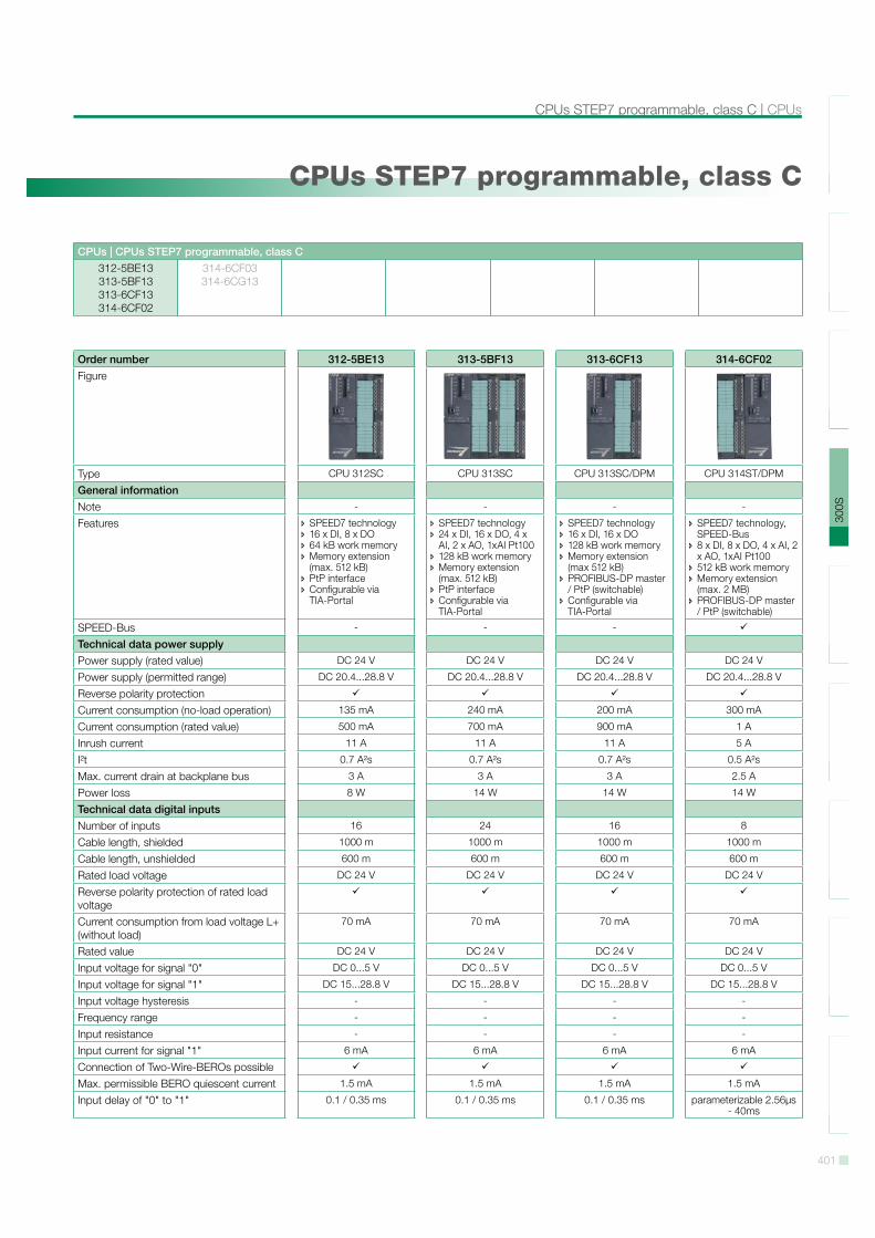
CPUs STEP7 programmable, class C
Order number 312-5BE13 313-5BF13 313-6CF13 314-6CF02Figure
Type CPU 312SC CPU 313SC CPU 313SC/DPM CPU 314ST/DPM
General informationNote - - - -
Features SPEED7 technology 16 x DI, 8 x DO 64 kB work memory Memory extension (max. 512 kB)
PtP interface Configurable via TIA-Portal
SPEED7 technology 24 x DI, 16 x DO, 4 x AI, 2 x AO, 1xAI Pt100
128 kB work memory Memory extension (max. 512 kB)
PtP interface Configurable via TIA-Portal
SPEED7 technology 16 x DI, 16 x DO 128 kB work memory Memory extension (max 512 kB)
PROFIBUS-DP master / PtP (switchable)
Configurable via TIA-Portal
SPEED7 technology, SPEED-Bus
8 x DI, 8 x DO, 4 x AI, 2 x AO, 1xAI Pt100
512 kB work memory Memory extension (max. 2 MB)
PROFIBUS-DP master / PtP (switchable)
SPEED-Bus - - -
Technical data power supplyPower supply (rated value) DC 24 V DC 24 V DC 24 V DC 24 V
Power supply (permitted range) DC 20.4...28.8 V DC 20.4...28.8 V DC 20.4...28.8 V DC 20.4...28.8 V
Reverse polarity protectionCurrent consumption (no-load operation) 135 mA 240 mA 200 mA 300 mA
Current consumption (rated value) 500 mA 700 mA 900 mA 1 A
Inrush current 11 A 11 A 11 A 5 A
I!t 0.7 A!s 0.7 A!s 0.7 A!s 0.5 A!s
Max. current drain at backplane bus 3 A 3 A 3 A 2.5 A
Power loss 8 W 14 W 14 W 14 W
Technical data digital inputsNumber of inputs 16 24 16 8
Cable length, shielded 1000 m 1000 m 1000 m 1000 m
Cable length, unshielded 600 m 600 m 600 m 600 m
Rated load voltage DC 24 V DC 24 V DC 24 V DC 24 V
Reverse polarity protection of rated load voltageCurrent consumption from load voltage L+ (without load)
70 mA 70 mA 70 mA 70 mA
Rated value DC 24 V DC 24 V DC 24 V DC 24 V
Input voltage for signal "0" DC 0...5 V DC 0...5 V DC 0...5 V DC 0...5 V
Input voltage for signal "1" DC 15...28.8 V DC 15...28.8 V DC 15...28.8 V DC 15...28.8 V
Input voltage hysteresis - - - -
Frequency range - - - -
Input resistance - - - -
Input current for signal "1" 6 mA 6 mA 6 mA 6 mA
Connection of Two-Wire-BEROs possibleMax. permissible BERO quiescent current 1.5 mA 1.5 mA 1.5 mA 1.5 mA
Input delay of "0" to "1" 0.1 / 0.35 ms 0.1 / 0.35 ms 0.1 / 0.35 ms parameterizable 2.56µs - 40ms
402
SLI
O10
0V20
0V30
0S50
0SH
MI
Sof
twar
eA
cces
sorie
sA
ppen
dix
CPUs | CPUs STEP7 programmable, class C
CPUs | CPUs STEP7 programmable, class C312-5BE13313-5BF13313-6CF13314-6CF02
314-6CF03314-6CG13
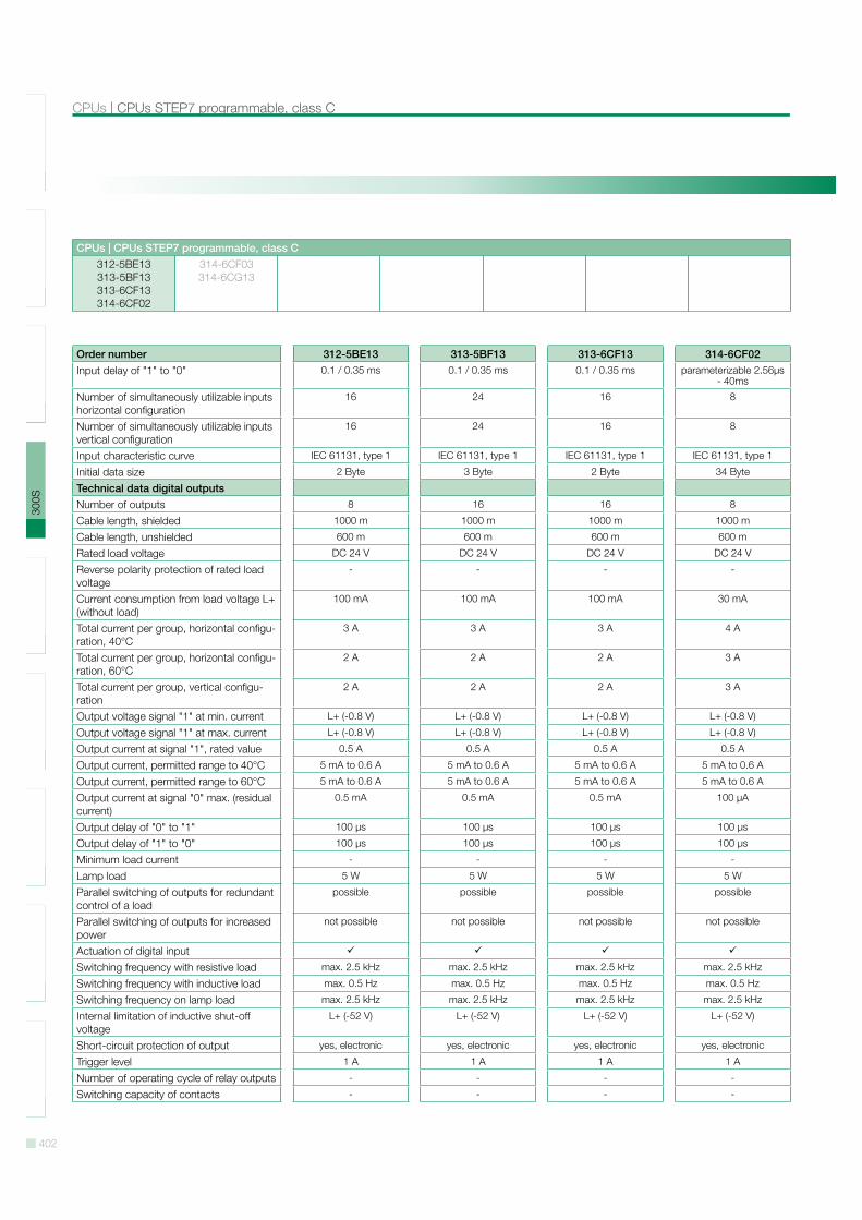
Order number 312-5BE13 313-5BF13 313-6CF13 314-6CF02Input delay of "1" to "0" 0.1 / 0.35 ms 0.1 / 0.35 ms 0.1 / 0.35 ms parameterizable 2.56µs
- 40ms
Number of simultaneously utilizable inputs horizontal configuration
16 24 16 8
Number of simultaneously utilizable inputs vertical configuration
16 24 16 8
Input characteristic curve IEC 61131, type 1 IEC 61131, type 1 IEC 61131, type 1 IEC 61131, type 1
Initial data size 2 Byte 3 Byte 2 Byte 34 Byte
Technical data digital outputsNumber of outputs 8 16 16 8
Cable length, shielded 1000 m 1000 m 1000 m 1000 m
Cable length, unshielded 600 m 600 m 600 m 600 m
Rated load voltage DC 24 V DC 24 V DC 24 V DC 24 V
Reverse polarity protection of rated load voltage
- - - -
Current consumption from load voltage L+ (without load)
100 mA 100 mA 100 mA 30 mA
Total current per group, horizontal configu-ration, 40°C
3 A 3 A 3 A 4 A
Total current per group, horizontal configu-ration, 60°C
2 A 2 A 2 A 3 A
Total current per group, vertical configu-ration
2 A 2 A 2 A 3 A
Output voltage signal "1" at min. current L+ (-0.8 V) L+ (-0.8 V) L+ (-0.8 V) L+ (-0.8 V)
Output voltage signal "1" at max. current L+ (-0.8 V) L+ (-0.8 V) L+ (-0.8 V) L+ (-0.8 V)
Output current at signal "1", rated value 0.5 A 0.5 A 0.5 A 0.5 A
Output current, permitted range to 40°C 5 mA to 0.6 A 5 mA to 0.6 A 5 mA to 0.6 A 5 mA to 0.6 A
Output current, permitted range to 60°C 5 mA to 0.6 A 5 mA to 0.6 A 5 mA to 0.6 A 5 mA to 0.6 A
Output current at signal "0" max. (residual current)
0.5 mA 0.5 mA 0.5 mA 100 µA
Output delay of "0" to "1" 100 µs 100 µs 100 µs 100 µs
Output delay of "1" to "0" 100 µs 100 µs 100 µs 100 µs
Minimum load current - - - -
Lamp load 5 W 5 W 5 W 5 W
Parallel switching of outputs for redundant control of a load
possible possible possible possible
Parallel switching of outputs for increased power
not possible not possible not possible not possible
Actuation of digital inputSwitching frequency with resistive load max. 2.5 kHz max. 2.5 kHz max. 2.5 kHz max. 2.5 kHz
Switching frequency with inductive load max. 0.5 Hz max. 0.5 Hz max. 0.5 Hz max. 0.5 Hz
Switching frequency on lamp load max. 2.5 kHz max. 2.5 kHz max. 2.5 kHz max. 2.5 kHz
Internal limitation of inductive shut-off voltage
L+ (-52 V) L+ (-52 V) L+ (-52 V) L+ (-52 V)
Short-circuit protection of output yes, electronic yes, electronic yes, electronic yes, electronic
Trigger level 1 A 1 A 1 A 1 A
Number of operating cycle of relay outputs - - - -
Switching capacity of contacts - - - -
403
SLI
O10
0V20
0V30
0S50
0SH
MI
Sof
twar
eA
cces
sorie
sA
ppen
dix
CPUs STEP7 programmable, class C | CPUs
CPUs | CPUs STEP7 programmable, class C312-5BE13313-5BF13313-6CF13314-6CF02
314-6CF03314-6CG13
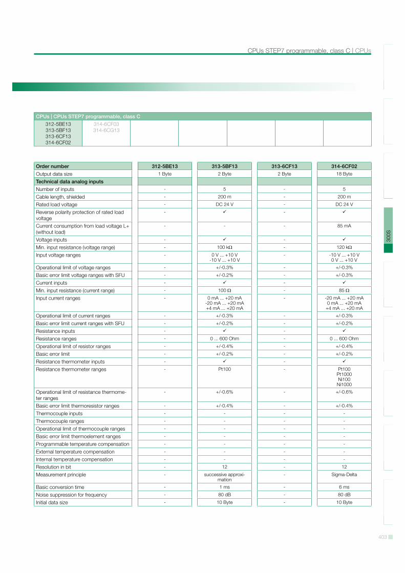
Order number 312-5BE13 313-5BF13 313-6CF13 314-6CF02Output data size 1 Byte 2 Byte 2 Byte 18 Byte
Technical data analog inputsNumber of inputs - 5 - 5
Cable length, shielded - 200 m - 200 m
Rated load voltage - DC 24 V - DC 24 V
Reverse polarity protection of rated load voltage
- -
Current consumption from load voltage L+ (without load)
- - - 85 mA
Voltage inputs - -
Min. input resistance (voltage range) - 100 k - 120 k
Input voltage ranges - 0 V ... +10 V-10 V ... +10 V
- -10 V ... +10 V0 V ... +10 V
Operational limit of voltage ranges - +/-0.3% - +/-0.3%
Basic error limit voltage ranges with SFU - +/-0.2% - +/-0.3%
Current inputs - -
Min. input resistance (current range) - 100 - 85
Input current ranges - 0 mA ... +20 mA-20 mA ... +20 mA+4 mA ... +20 mA
- -20 mA ... +20 mA0 mA ... +20 mA
+4 mA ... +20 mA
Operational limit of current ranges - +/-0.3% - +/-0.3%
Basic error limit current ranges with SFU - +/-0.2% - +/-0.2%
Resistance inputs - -
Resistance ranges - 0 ... 600 Ohm - 0 ... 600 Ohm
Operational limit of resistor ranges - +/-0.4% - +/-0.4%
Basic error limit - +/-0.2% - +/-0.2%
Resistance thermometer inputs - -
Resistance thermometer ranges - Pt100 - Pt100Pt1000Ni100
Ni1000
Operational limit of resistance thermome-ter ranges
- +/-0.6% - +/-0.6%
Basic error limit thermoresistor ranges - +/-0.4% - +/-0.4%
Thermocouple inputs - - - -
Thermocouple ranges - - - -
Operational limit of thermocouple ranges - - - -
Basic error limit thermoelement ranges - - - -
Programmable temperature compensation - - - -
External temperature compensation - - - -
Internal temperature compensation - - - -
Resolution in bit - 12 - 12
Measurement principle - successive approxi-mation
- Sigma-Delta
Basic conversion time - 1 ms - 6 ms
Noise suppression for frequency - 80 dB - 80 dB
Initial data size - 10 Byte - 10 Byte
404
SLI
O10
0V20
0V30
0S50
0SH
MI
Sof
twar
eA
cces
sorie
sA
ppen
dix
CPUs | CPUs STEP7 programmable, class C
CPUs | CPUs STEP7 programmable, class C312-5BE13313-5BF13313-6CF13314-6CF02
314-6CF03314-6CG13
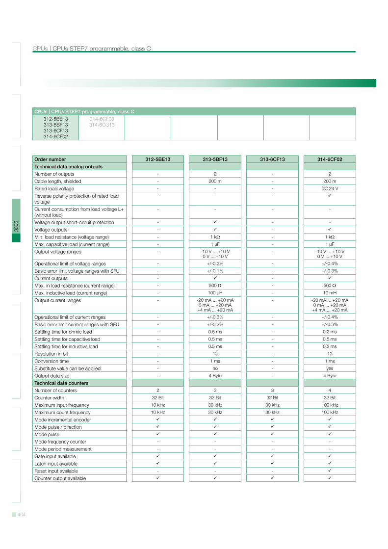
Order number 312-5BE13 313-5BF13 313-6CF13 314-6CF02Technical data analog outputsNumber of outputs - 2 - 2
Cable length, shielded - 200 m - 200 m
Rated load voltage - - - DC 24 V
Reverse polarity protection of rated load voltage
- - -
Current consumption from load voltage L+ (without load)
- - - -
Voltage output short-circuit protection - - -
Voltage outputs - -
Min. load resistance (voltage range) - 1 k - 1 k
Max. capacitive load (current range) - 1 µF - 1 µF
Output voltage ranges - -10 V ... +10 V0 V ... +10 V
- -10 V ... +10 V0 V ... +10 V
Operational limit of voltage ranges - +/-0.2% - +/-0.4%
Basic error limit voltage ranges with SFU - +/-0.1% - +/-0.3%
Current outputs - -
Max. in load resistance (current range) - 500 - 500
Max. inductive load (current range) - 100 µH - 10 mH
Output current ranges - -20 mA ... +20 mA0 mA ... +20 mA
+4 mA ... +20 mA
- -20 mA ... +20 mA0 mA ... +20 mA
+4 mA ... +20 mA
Operational limit of current ranges - +/-0.3% - +/-0.4%
Basic error limit current ranges with SFU - +/-0.2% - +/-0.3%
Settling time for ohmic load - 0.5 ms - 0.2 ms
Settling time for capacitive load - 0.5 ms - 0.5 ms
Settling time for inductive load - 0.5 ms - 0.2 ms
Resolution in bit - 12 - 12
Conversion time - 1 ms - 1 ms
Substitute value can be applied - no - yes
Output data size - 4 Byte - 4 Byte
Technical data countersNumber of counters 2 3 3 4
Counter width 32 Bit 32 Bit 32 Bit 32 Bit
Maximum input frequency 10 kHz 30 kHz 30 kHz 100 kHz
Maximum count frequency 10 kHz 30 kHz 30 kHz 100 kHz
Mode incremental encoderMode pulse / directionMode pulseMode frequency counter - - - -
Mode period measurement - - - -
Gate input availableLatch input availableReset input available - - -
Counter output available
405
SLI
O10
0V20
0V30
0S50
0SH
MI
Sof
twar
eA
cces
sorie
sA
ppen
dix
CPUs STEP7 programmable, class C | CPUs
CPUs | CPUs STEP7 programmable, class C312-5BE13313-5BF13313-6CF13314-6CF02
314-6CF03314-6CG13
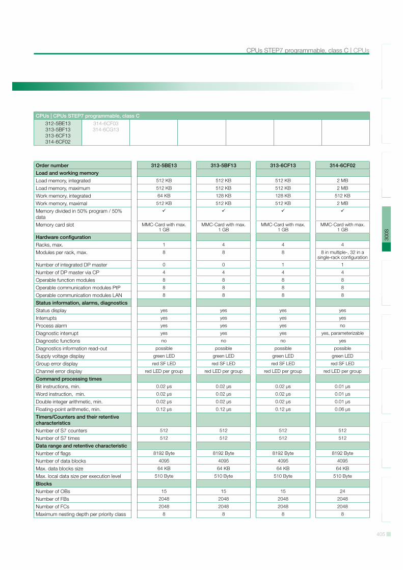
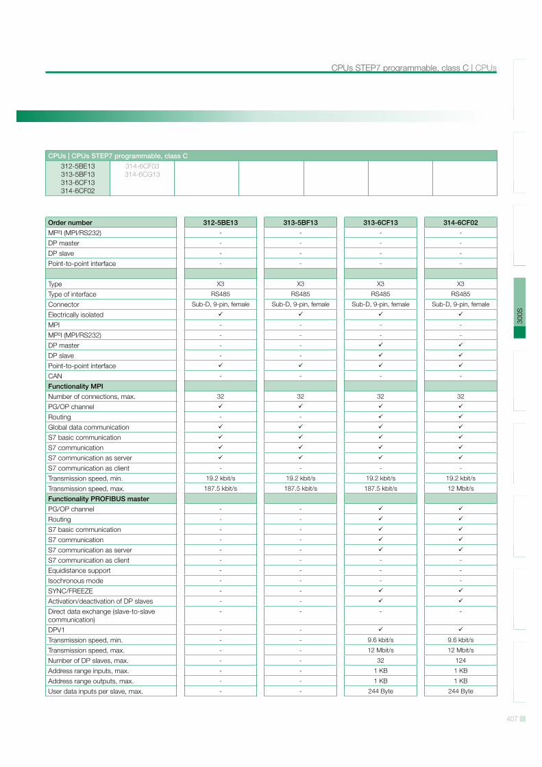
Order number 312-5BE13 313-5BF13 313-6CF13 314-6CF02Load and working memoryLoad memory, integrated 512 KB 512 KB 512 KB 2 MB
Load memory, maximum 512 KB 512 KB 512 KB 2 MB
Work memory, integrated 64 KB 128 KB 128 KB 512 KB
Work memory, maximal 512 KB 512 KB 512 KB 2 MB
Memory divided in 50% program / 50% dataMemory card slot MMC-Card with max.
1 GBMMC-Card with max.
1 GBMMC-Card with max.
1 GBMMC-Card with max.
1 GB
Hardware configurationRacks, max. 1 4 4 4
Modules per rack, max. 8 8 8 8 in multiple-, 32 in a single-rack configuration
Number of integrated DP master 0 0 1 1
Number of DP master via CP 4 4 4 4
Operable function modules 8 8 8 8
Operable communication modules PtP 8 8 8 8
Operable communication modules LAN 8 8 8 8
Status information, alarms, diagnosticsStatus display yes yes yes yes
Interrupts yes yes yes yes
Process alarm yes yes yes no
Diagnostic interrupt yes yes yes yes, parameterizable
Diagnostic functions no no no yes
Diagnostics information read-out possible possible possible possible
Supply voltage display green LED green LED green LED green LED
Group error display red SF LED red SF LED red SF LED red SF LED
Channel error display red LED per group red LED per group red LED per group red LED per group
Command processing timesBit instructions, min. 0.02 µs 0.02 µs 0.02 µs 0.01 µs
Word instruction, min. 0.02 µs 0.02 µs 0.02 µs 0.01 µs
Double integer arithmetic, min. 0.02 µs 0.02 µs 0.02 µs 0.01 µs
Floating-point arithmetic, min. 0.12 µs 0.12 µs 0.12 µs 0.06 µs
Timers/Counters and their retentive characteristicsNumber of S7 counters 512 512 512 512
Number of S7 times 512 512 512 512
Data range and retentive characteristicNumber of flags 8192 Byte 8192 Byte 8192 Byte 8192 Byte
Number of data blocks 4095 4095 4095 4095
Max. data blocks size 64 KB 64 KB 64 KB 64 KB
Max. local data size per execution level 510 Byte 510 Byte 510 Byte 510 Byte
BlocksNumber of OBs 15 15 15 24
Number of FBs 2048 2048 2048 2048
Number of FCs 2048 2048 2048 2048
Maximum nesting depth per priority class 8 8 8 8
406
SLI
O10
0V20
0V30
0S50
0SH
MI
Sof
twar
eA
cces
sorie
sA
ppen
dix
CPUs | CPUs STEP7 programmable, class C
CPUs | CPUs STEP7 programmable, class C312-5BE13313-5BF13313-6CF13314-6CF02
314-6CF03314-6CG13
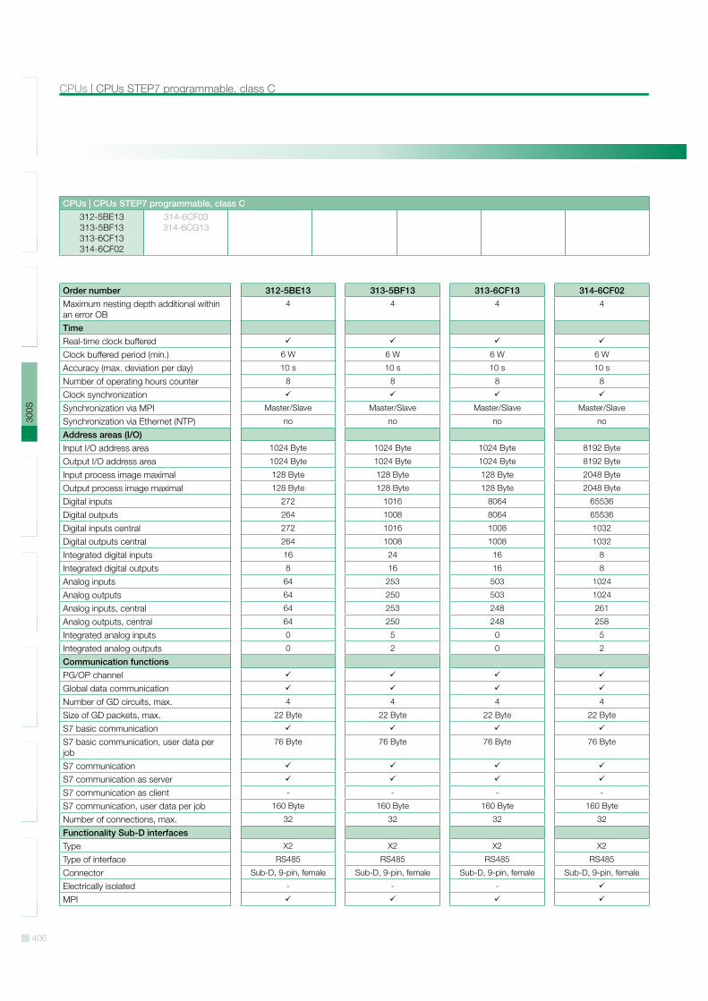
Order number 312-5BE13 313-5BF13 313-6CF13 314-6CF02Maximum nesting depth additional within an error OB
4 4 4 4
TimeReal-time clock bufferedClock buffered period (min.) 6 W 6 W 6 W 6 W
Accuracy (max. deviation per day) 10 s 10 s 10 s 10 s
Number of operating hours counter 8 8 8 8
Clock synchronizationSynchronization via MPI Master/Slave Master/Slave Master/Slave Master/Slave
Synchronization via Ethernet (NTP) no no no no
Address areas (I/O)Input I/O address area 1024 Byte 1024 Byte 1024 Byte 8192 Byte
Output I/O address area 1024 Byte 1024 Byte 1024 Byte 8192 Byte
Input process image maximal 128 Byte 128 Byte 128 Byte 2048 Byte
Output process image maximal 128 Byte 128 Byte 128 Byte 2048 Byte
Digital inputs 272 1016 8064 65536
Digital outputs 264 1008 8064 65536
Digital inputs central 272 1016 1008 1032
Digital outputs central 264 1008 1008 1032
Integrated digital inputs 16 24 16 8
Integrated digital outputs 8 16 16 8
Analog inputs 64 253 503 1024
Analog outputs 64 250 503 1024
Analog inputs, central 64 253 248 261
Analog outputs, central 64 250 248 258
Integrated analog inputs 0 5 0 5
Integrated analog outputs 0 2 0 2
Communication functionsPG/OP channelGlobal data communicationNumber of GD circuits, max. 4 4 4 4
Size of GD packets, max. 22 Byte 22 Byte 22 Byte 22 Byte
S7 basic communicationS7 basic communication, user data per job
76 Byte 76 Byte 76 Byte 76 Byte
S7 communicationS7 communication as serverS7 communication as client - - - -
S7 communication, user data per job 160 Byte 160 Byte 160 Byte 160 Byte
Number of connections, max. 32 32 32 32
Functionality Sub-D interfacesType X2 X2 X2 X2
Type of interface RS485 RS485 RS485 RS485
Connector Sub-D, 9-pin, female Sub-D, 9-pin, female Sub-D, 9-pin, female Sub-D, 9-pin, female
Electrically isolated - - -
MPI
407
SLI
O10
0V20
0V30
0S50
0SH
MI
Sof
twar
eA
cces
sorie
sA
ppen
dix
CPUs STEP7 programmable, class C | CPUs
CPUs | CPUs STEP7 programmable, class C312-5BE13313-5BF13313-6CF13314-6CF02
314-6CF03314-6CG13
Order number 312-5BE13 313-5BF13 313-6CF13 314-6CF02MP!I (MPI/RS232) - - - -
DP master - - - -
DP slave - - - -
Point-to-point interface - - - -
Type X3 X3 X3 X3
Type of interface RS485 RS485 RS485 RS485
Connector Sub-D, 9-pin, female Sub-D, 9-pin, female Sub-D, 9-pin, female Sub-D, 9-pin, female
Electrically isolatedMPI - - - -
MP!I (MPI/RS232) - - - -
DP master - -
DP slave - -
Point-to-point interfaceCAN - - - -
Functionality MPINumber of connections, max. 32 32 32 32
PG/OP channelRouting - -
Global data communicationS7 basic communicationS7 communicationS7 communication as serverS7 communication as client - - - -
Transmission speed, min. 19.2 kbit/s 19.2 kbit/s 19.2 kbit/s 19.2 kbit/s
Transmission speed, max. 187.5 kbit/s 187.5 kbit/s 187.5 kbit/s 12 Mbit/s
Functionality PROFIBUS masterPG/OP channel - -
Routing - -
S7 basic communication - -
S7 communication - -
S7 communication as server - -
S7 communication as client - - - -
Equidistance support - - - -
Isochronous mode - - - -
SYNC/FREEZE - -
Activation/deactivation of DP slaves - -
Direct data exchange (slave-to-slave communication)
- - - -
DPV1 - -
Transmission speed, min. - - 9.6 kbit/s 9.6 kbit/s
Transmission speed, max. - - 12 Mbit/s 12 Mbit/s
Number of DP slaves, max. - - 32 124
Address range inputs, max. - - 1 KB 1 KB
Address range outputs, max. - - 1 KB 1 KB
User data inputs per slave, max. - - 244 Byte 244 Byte
408
SLI
O10
0V20
0V30
0S50
0SH
MI
Sof
twar
eA
cces
sorie
sA
ppen
dix
CPUs | CPUs STEP7 programmable, class C
CPUs | CPUs STEP7 programmable, class C312-5BE13313-5BF13313-6CF13314-6CF02
314-6CF03314-6CG13
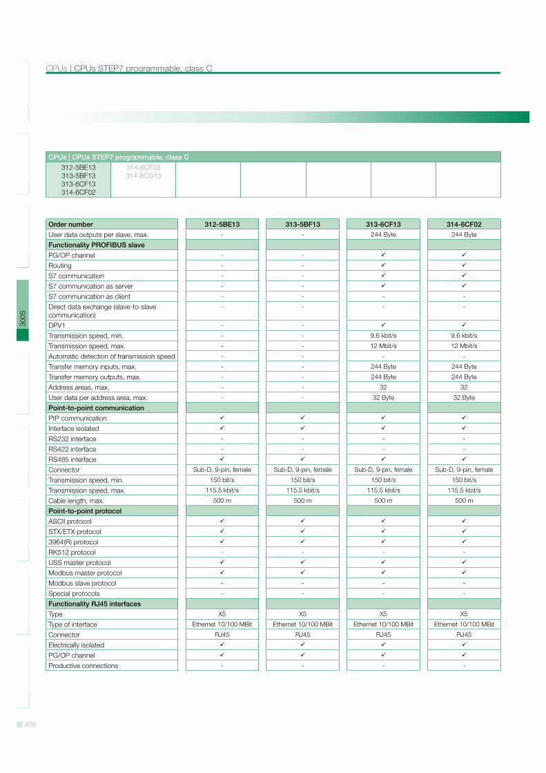
Order number 312-5BE13 313-5BF13 313-6CF13 314-6CF02User data outputs per slave, max. - - 244 Byte 244 Byte
Functionality PROFIBUS slavePG/OP channel - -
Routing - -
S7 communication - -
S7 communication as server - -
S7 communication as client - - - -
Direct data exchange (slave-to-slave communication)
- - - -
DPV1 - -
Transmission speed, min. - - 9.6 kbit/s 9.6 kbit/s
Transmission speed, max. - - 12 Mbit/s 12 Mbit/s
Automatic detection of transmission speed - - - -
Transfer memory inputs, max. - - 244 Byte 244 Byte
Transfer memory outputs, max. - - 244 Byte 244 Byte
Address areas, max. - - 32 32
User data per address area, max. - - 32 Byte 32 Byte
Point-to-point communicationPtP communicationInterface isolatedRS232 interface - - - -
RS422 interface - - - -
RS485 interfaceConnector Sub-D, 9-pin, female Sub-D, 9-pin, female Sub-D, 9-pin, female Sub-D, 9-pin, female
Transmission speed, min. 150 bit/s 150 bit/s 150 bit/s 150 bit/s
Transmission speed, max. 115.5 kbit/s 115.5 kbit/s 115.5 kbit/s 115.5 kbit/s
Cable length, max. 500 m 500 m 500 m 500 m
Point-to-point protocolASCII protocolSTX/ETX protocol3964(R) protocolRK512 protocol - - - -
USS master protocolModbus master protocolModbus slave protocol - - - -
Special protocols - - - -
Functionality RJ45 interfacesType X5 X5 X5 X5
Type of interface Ethernet 10/100 MBit Ethernet 10/100 MBit Ethernet 10/100 MBit Ethernet 10/100 MBit
Connector RJ45 RJ45 RJ45 RJ45
Electrically isolatedPG/OP channelProductive connections - - - -
409
SLI
O10
0V20
0V30
0S50
0SH
MI
Sof
twar
eA
cces
sorie
sA
ppen
dix
CPUs STEP7 programmable, class C | CPUs
CPUs | CPUs STEP7 programmable, class C312-5BE13313-5BF13313-6CF13314-6CF02
314-6CF03314-6CG13
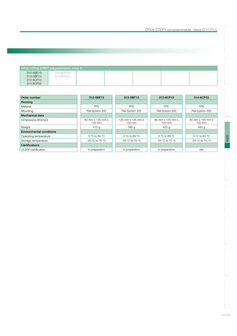
Order number 312-5BE13 313-5BF13 313-6CF13 314-6CF02HousingMaterial PPE PPE PPE PPE
Mounting Rail System 300 Rail System 300 Rail System 300 Rail System 300
Mechanical dataDimensions (WxHxD) 80 mm x 125 mm x
120 mm120 mm x 125 mm x
120 mm80 mm x 125 mm x
120 mm80 mm x 125 mm x
120 mm
Weight 410 g 590 g 420 g 480 g
Environmental conditionsOperating temperature 0 °C to 60 °C 0 °C to 60 °C 0 °C to 60 °C 0 °C to 60 °C
Storage temperature -25 °C to 70 °C -25 °C to 70 °C -25 °C to 70 °C -25 °C to 70 °C
CertificationsUL508 certification in preparation in preparation in preparation yes

410
SLI
O10
0V20
0V30
0S50
0SH
MI
Sof
twar
eA
cces
sorie
sA
ppen
dix
CPUs | CPUs STEP7 programmable, class C
CPUs | CPUs STEP7 programmable, class C312-5BE13313-5BF13313-6CF13314-6CF02
314-6CF03314-6CG13
Connections, Interfaces
312-5BE13
313-5BF13
411
SLI
O10
0V20
0V30
0S50
0SH
MI
Sof
twar
eA
cces
sorie
sA
ppen
dix
CPUs STEP7 programmable, class C | CPUs
CPUs | CPUs STEP7 programmable, class C312-5BE13313-5BF13313-6CF13314-6CF02
314-6CF03314-6CG13
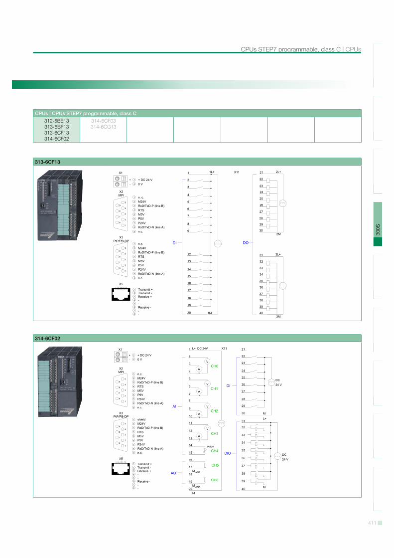
313-6CF13
314-6CF02
412
SLI
O10
0V20
0V30
0S50
0SH
MI
Sof
twar
eA
cces
sorie
sA
ppen
dix
CPUs | CPUs STEP7 programmable, class C
CPUs | CPUs STEP7 programmable, class C312-5BE13313-5BF13313-6CF13314-6CF02
314-6CF03314-6CG13
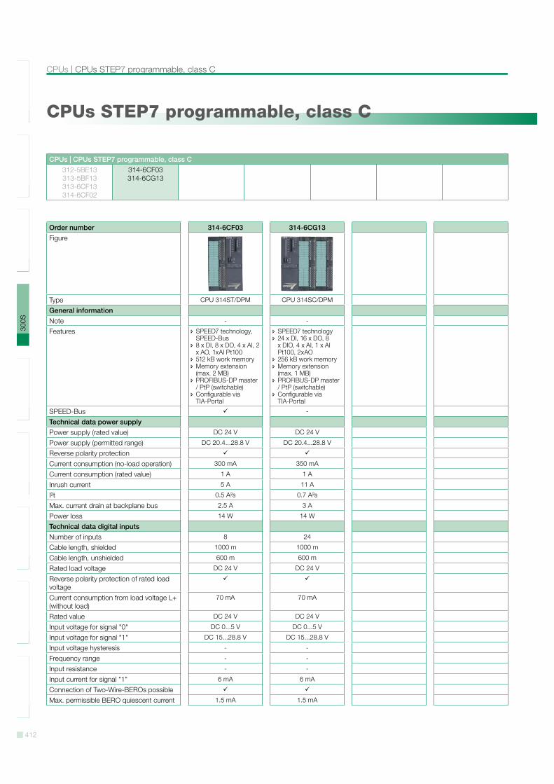
CPUs STEP7 programmable, class C
Order number 314-6CF03 314-6CG13Figure
Type CPU 314ST/DPM CPU 314SC/DPM
General informationNote - -
Features SPEED7 technology, SPEED-Bus
8 x DI, 8 x DO, 4 x AI, 2 x AO, 1xAI Pt100
512 kB work memory Memory extension (max. 2 MB)
PROFIBUS-DP master / PtP (switchable)
Configurable via TIA-Portal
SPEED7 technology 24 x DI, 16 x DO, 8 x DIO, 4 x AI, 1 x AI Pt100, 2xAO
256 kB work memory Memory extension (max. 1 MB)
PROFIBUS-DP master / PtP (switchable)
Configurable via TIA-Portal
SPEED-Bus -
Technical data power supplyPower supply (rated value) DC 24 V DC 24 V
Power supply (permitted range) DC 20.4...28.8 V DC 20.4...28.8 V
Reverse polarity protectionCurrent consumption (no-load operation) 300 mA 350 mA
Current consumption (rated value) 1 A 1 A
Inrush current 5 A 11 A
I!t 0.5 A!s 0.7 A!s
Max. current drain at backplane bus 2.5 A 3 A
Power loss 14 W 14 W
Technical data digital inputsNumber of inputs 8 24
Cable length, shielded 1000 m 1000 m
Cable length, unshielded 600 m 600 m
Rated load voltage DC 24 V DC 24 V
Reverse polarity protection of rated load voltageCurrent consumption from load voltage L+ (without load)
70 mA 70 mA
Rated value DC 24 V DC 24 V
Input voltage for signal "0" DC 0...5 V DC 0...5 V
Input voltage for signal "1" DC 15...28.8 V DC 15...28.8 V
Input voltage hysteresis - -
Frequency range - -
Input resistance - -
Input current for signal "1" 6 mA 6 mA
Connection of Two-Wire-BEROs possibleMax. permissible BERO quiescent current 1.5 mA 1.5 mA
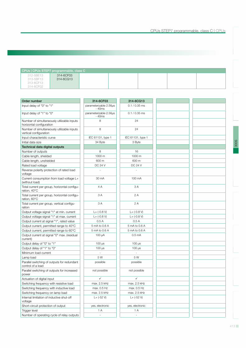
413
SLI
O10
0V20
0V30
0S50
0SH
MI
Sof
twar
eA
cces
sorie
sA
ppen
dix
CPUs STEP7 programmable, class C | CPUs
CPUs | CPUs STEP7 programmable, class C312-5BE13313-5BF13313-6CF13314-6CF02
314-6CF03314-6CG13
Order number 314-6CF03 314-6CG13Input delay of "0" to "1" parameterizable 2.56µs
- 40ms0.1 / 0.35 ms
Input delay of "1" to "0" parameterizable 2.56µs - 40ms
0.1 / 0.35 ms
Number of simultaneously utilizable inputs horizontal configuration
8 24
Number of simultaneously utilizable inputs vertical configuration
8 24
Input characteristic curve IEC 61131, type 1 IEC 61131, type 1
Initial data size 34 Byte 3 Byte
Technical data digital outputsNumber of outputs 8 16
Cable length, shielded 1000 m 1000 m
Cable length, unshielded 600 m 600 m
Rated load voltage DC 24 V DC 24 V
Reverse polarity protection of rated load voltage
- -
Current consumption from load voltage L+ (without load)
30 mA 100 mA
Total current per group, horizontal configu-ration, 40°C
4 A 3 A
Total current per group, horizontal configu-ration, 60°C
3 A 2 A
Total current per group, vertical configu-ration
3 A 2 A
Output voltage signal "1" at min. current L+ (-0.8 V) L+ (-0.8 V)
Output voltage signal "1" at max. current L+ (-0.8 V) L+ (-0.8 V)
Output current at signal "1", rated value 0.5 A 0.5 A
Output current, permitted range to 40°C 5 mA to 0.6 A 5 mA to 0.6 A
Output current, permitted range to 60°C 5 mA to 0.6 A 5 mA to 0.6 A
Output current at signal "0" max. (residual current)
100 µA 0.5 mA
Output delay of "0" to "1" 100 µs 100 µs
Output delay of "1" to "0" 100 µs 100 µs
Minimum load current - -
Lamp load 5 W 5 W
Parallel switching of outputs for redundant control of a load
possible possible
Parallel switching of outputs for increased power
not possible not possible
Actuation of digital inputSwitching frequency with resistive load max. 2.5 kHz max. 2.5 kHz
Switching frequency with inductive load max. 0.5 Hz max. 0.5 Hz
Switching frequency on lamp load max. 2.5 kHz max. 2.5 kHz
Internal limitation of inductive shut-off voltage
L+ (-52 V) L+ (-52 V)
Short-circuit protection of output yes, electronic yes, electronic
Trigger level 1 A 1 A
Number of operating cycle of relay outputs - -

414
SLI
O10
0V20
0V30
0S50
0SH
MI
Sof
twar
eA
cces
sorie
sA
ppen
dix
CPUs | CPUs STEP7 programmable, class C
CPUs | CPUs STEP7 programmable, class C312-5BE13313-5BF13313-6CF13314-6CF02
314-6CF03314-6CG13
Order number 314-6CF03 314-6CG13Switching capacity of contacts - -
Output data size 18 Byte 2 Byte
Technical data analog inputsNumber of inputs 5 5
Cable length, shielded 200 m 200 m
Rated load voltage DC 24 V DC 24 V
Reverse polarity protection of rated load voltageCurrent consumption from load voltage L+ (without load)
85 mA -
Voltage inputsMin. input resistance (voltage range) 120 k -
Input voltage ranges -10 V ... +10 V0 V ... +10 V
-10 V ... +10 V0 V ... +10 V
Operational limit of voltage ranges +/-0.3% +/-0.3%
Basic error limit voltage ranges with SFU +/-0.3% +/-0.2%
Current inputsMin. input resistance (current range) 85 100
Input current ranges -20 mA ... +20 mA0 mA ... +20 mA
+4 mA ... +20 mA
-20 mA ... +20 mA0 mA ... +20 mA
+4 mA ... +20 mA
Operational limit of current ranges +/-0.3% +/-0.3%
Basic error limit current ranges with SFU +/-0.2% +/-0.2%
Resistance inputsResistance ranges 0 ... 600 Ohm 0 ... 600 Ohm
Operational limit of resistor ranges +/-0.4% +/-0.4%
Basic error limit +/-0.2% +/-0.2%
Resistance thermometer inputs -
Resistance thermometer ranges Pt100Pt1000Ni100
Ni1000
Pt100
Operational limit of resistance thermome-ter ranges
+/-0.6% +/-0.6%
Basic error limit thermoresistor ranges +/-0.4% +/-0.4%
Thermocouple inputs - -
Thermocouple ranges - -
Operational limit of thermocouple ranges - -
Basic error limit thermoelement ranges - -
Programmable temperature compensation - -
External temperature compensation - -
Internal temperature compensation - -
Resolution in bit 12 12
Measurement principle Sigma-Delta successive approxi-mation
Basic conversion time 6 ms 0.5 ms
Noise suppression for frequency 80 dB 80 dB
Initial data size 10 Byte 10 Byte
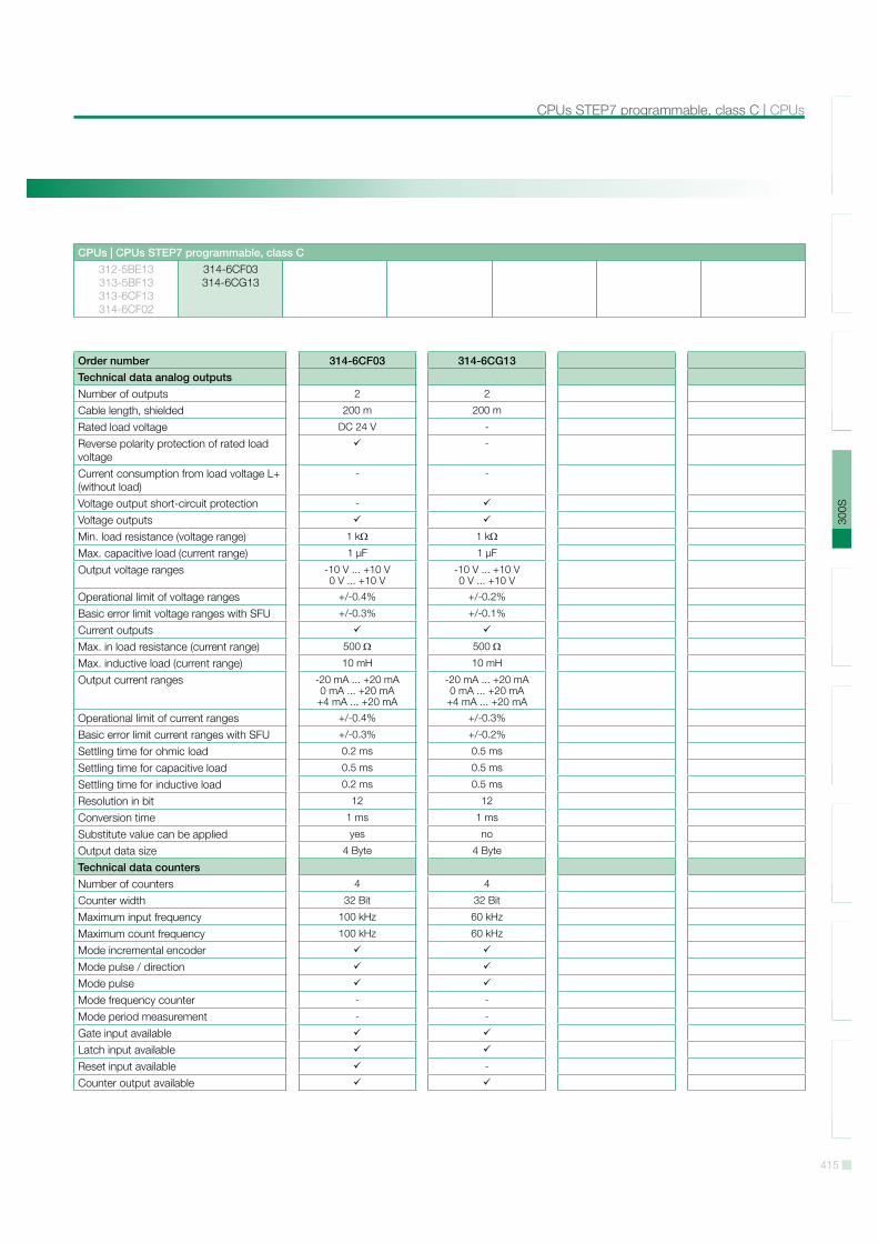
415
SLI
O10
0V20
0V30
0S50
0SH
MI
Sof
twar
eA
cces
sorie
sA
ppen
dix
CPUs STEP7 programmable, class C | CPUs
CPUs | CPUs STEP7 programmable, class C312-5BE13313-5BF13313-6CF13314-6CF02
314-6CF03314-6CG13
Order number 314-6CF03 314-6CG13Technical data analog outputsNumber of outputs 2 2
Cable length, shielded 200 m 200 m
Rated load voltage DC 24 V -
Reverse polarity protection of rated load voltage
-
Current consumption from load voltage L+ (without load)
- -
Voltage output short-circuit protection -
Voltage outputsMin. load resistance (voltage range) 1 k 1 k
Max. capacitive load (current range) 1 µF 1 µF
Output voltage ranges -10 V ... +10 V0 V ... +10 V
-10 V ... +10 V0 V ... +10 V
Operational limit of voltage ranges +/-0.4% +/-0.2%
Basic error limit voltage ranges with SFU +/-0.3% +/-0.1%
Current outputsMax. in load resistance (current range) 500 500
Max. inductive load (current range) 10 mH 10 mH
Output current ranges -20 mA ... +20 mA0 mA ... +20 mA
+4 mA ... +20 mA
-20 mA ... +20 mA0 mA ... +20 mA
+4 mA ... +20 mA
Operational limit of current ranges +/-0.4% +/-0.3%
Basic error limit current ranges with SFU +/-0.3% +/-0.2%
Settling time for ohmic load 0.2 ms 0.5 ms
Settling time for capacitive load 0.5 ms 0.5 ms
Settling time for inductive load 0.2 ms 0.5 ms
Resolution in bit 12 12
Conversion time 1 ms 1 ms
Substitute value can be applied yes no
Output data size 4 Byte 4 Byte
Technical data countersNumber of counters 4 4
Counter width 32 Bit 32 Bit
Maximum input frequency 100 kHz 60 kHz
Maximum count frequency 100 kHz 60 kHz
Mode incremental encoderMode pulse / directionMode pulseMode frequency counter - -
Mode period measurement - -
Gate input availableLatch input availableReset input available -
Counter output available
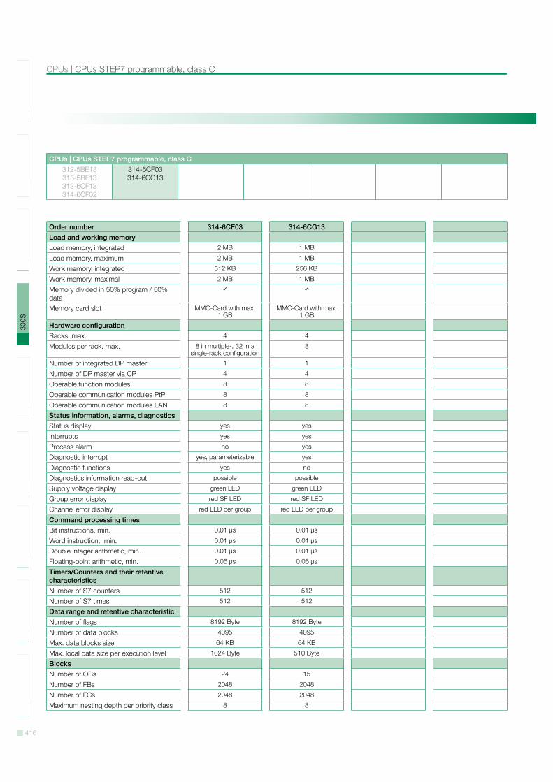
416
SLI
O10
0V20
0V30
0S50
0SH
MI
Sof
twar
eA
cces
sorie
sA
ppen
dix
CPUs | CPUs STEP7 programmable, class C
CPUs | CPUs STEP7 programmable, class C312-5BE13313-5BF13313-6CF13314-6CF02
314-6CF03314-6CG13
Order number 314-6CF03 314-6CG13Load and working memoryLoad memory, integrated 2 MB 1 MB
Load memory, maximum 2 MB 1 MB
Work memory, integrated 512 KB 256 KB
Work memory, maximal 2 MB 1 MB
Memory divided in 50% program / 50% dataMemory card slot MMC-Card with max.
1 GBMMC-Card with max.
1 GB
Hardware configurationRacks, max. 4 4
Modules per rack, max. 8 in multiple-, 32 in a single-rack configuration
8
Number of integrated DP master 1 1
Number of DP master via CP 4 4
Operable function modules 8 8
Operable communication modules PtP 8 8
Operable communication modules LAN 8 8
Status information, alarms, diagnosticsStatus display yes yes
Interrupts yes yes
Process alarm no yes
Diagnostic interrupt yes, parameterizable yes
Diagnostic functions yes no
Diagnostics information read-out possible possible
Supply voltage display green LED green LED
Group error display red SF LED red SF LED
Channel error display red LED per group red LED per group
Command processing timesBit instructions, min. 0.01 µs 0.01 µs
Word instruction, min. 0.01 µs 0.01 µs
Double integer arithmetic, min. 0.01 µs 0.01 µs
Floating-point arithmetic, min. 0.06 µs 0.06 µs
Timers/Counters and their retentive characteristicsNumber of S7 counters 512 512
Number of S7 times 512 512
Data range and retentive characteristicNumber of flags 8192 Byte 8192 Byte
Number of data blocks 4095 4095
Max. data blocks size 64 KB 64 KB
Max. local data size per execution level 1024 Byte 510 Byte
BlocksNumber of OBs 24 15
Number of FBs 2048 2048
Number of FCs 2048 2048
Maximum nesting depth per priority class 8 8
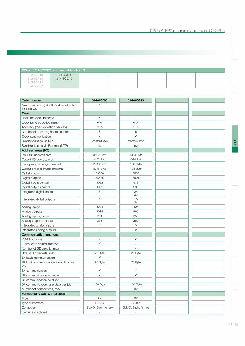
417
SLI
O10
0V20
0V30
0S50
0SH
MI
Sof
twar
eA
cces
sorie
sA
ppen
dix
CPUs STEP7 programmable, class C | CPUs
CPUs | CPUs STEP7 programmable, class C312-5BE13313-5BF13313-6CF13314-6CF02
314-6CF03314-6CG13
Order number 314-6CF03 314-6CG13Maximum nesting depth additional within an error OB
4 4
TimeReal-time clock bufferedClock buffered period (min.) 6 W 6 W
Accuracy (max. deviation per day) 10 s 10 s
Number of operating hours counter 8 8
Clock synchronizationSynchronization via MPI Master/Slave Master/Slave
Synchronization via Ethernet (NTP) no no
Address areas (I/O)Input I/O address area 8192 Byte 1024 Byte
Output I/O address area 8192 Byte 1024 Byte
Input process image maximal 2048 Byte 128 Byte
Output process image maximal 2048 Byte 128 Byte
Digital inputs 65536 7856
Digital outputs 65536 7904
Digital inputs central 1032 979
Digital outputs central 1032 986
Integrated digital inputs 8 24 32
Integrated digital outputs 8 16 24
Analog inputs 1024 494
Analog outputs 1024 495
Analog inputs, central 261 253
Analog outputs, central 258 250
Integrated analog inputs 5 5
Integrated analog outputs 2 2
Communication functionsPG/OP channelGlobal data communicationNumber of GD circuits, max. 4 4
Size of GD packets, max. 22 Byte 22 Byte
S7 basic communicationS7 basic communication, user data per job
76 Byte 76 Byte
S7 communicationS7 communication as serverS7 communication as client - -
S7 communication, user data per job 160 Byte 160 Byte
Number of connections, max. 32 32
Functionality Sub-D interfacesType X2 X2
Type of interface RS485 RS485
Connector Sub-D, 9-pin, female Sub-D, 9-pin, female
Electrically isolated -
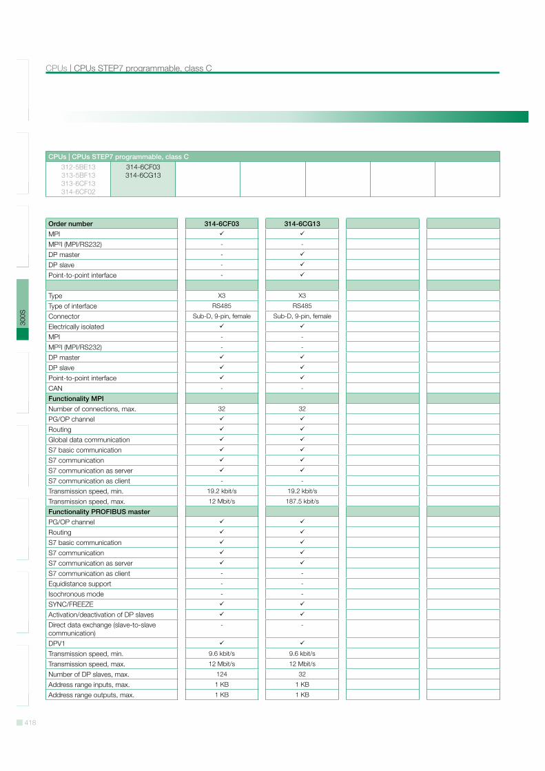
418
SLI
O10
0V20
0V30
0S50
0SH
MI
Sof
twar
eA
cces
sorie
sA
ppen
dix
CPUs | CPUs STEP7 programmable, class C
CPUs | CPUs STEP7 programmable, class C312-5BE13313-5BF13313-6CF13314-6CF02
314-6CF03314-6CG13
Order number 314-6CF03 314-6CG13MPIMP!I (MPI/RS232) - -
DP master -
DP slave -
Point-to-point interface -
Type X3 X3
Type of interface RS485 RS485
Connector Sub-D, 9-pin, female Sub-D, 9-pin, female
Electrically isolatedMPI - -
MP!I (MPI/RS232) - -
DP masterDP slavePoint-to-point interfaceCAN - -
Functionality MPINumber of connections, max. 32 32
PG/OP channelRoutingGlobal data communicationS7 basic communicationS7 communicationS7 communication as serverS7 communication as client - -
Transmission speed, min. 19.2 kbit/s 19.2 kbit/s
Transmission speed, max. 12 Mbit/s 187.5 kbit/s
Functionality PROFIBUS masterPG/OP channelRoutingS7 basic communicationS7 communicationS7 communication as serverS7 communication as client - -
Equidistance support - -
Isochronous mode - -
SYNC/FREEZEActivation/deactivation of DP slavesDirect data exchange (slave-to-slave communication)
- -
DPV1Transmission speed, min. 9.6 kbit/s 9.6 kbit/s
Transmission speed, max. 12 Mbit/s 12 Mbit/s
Number of DP slaves, max. 124 32
Address range inputs, max. 1 KB 1 KB
Address range outputs, max. 1 KB 1 KB
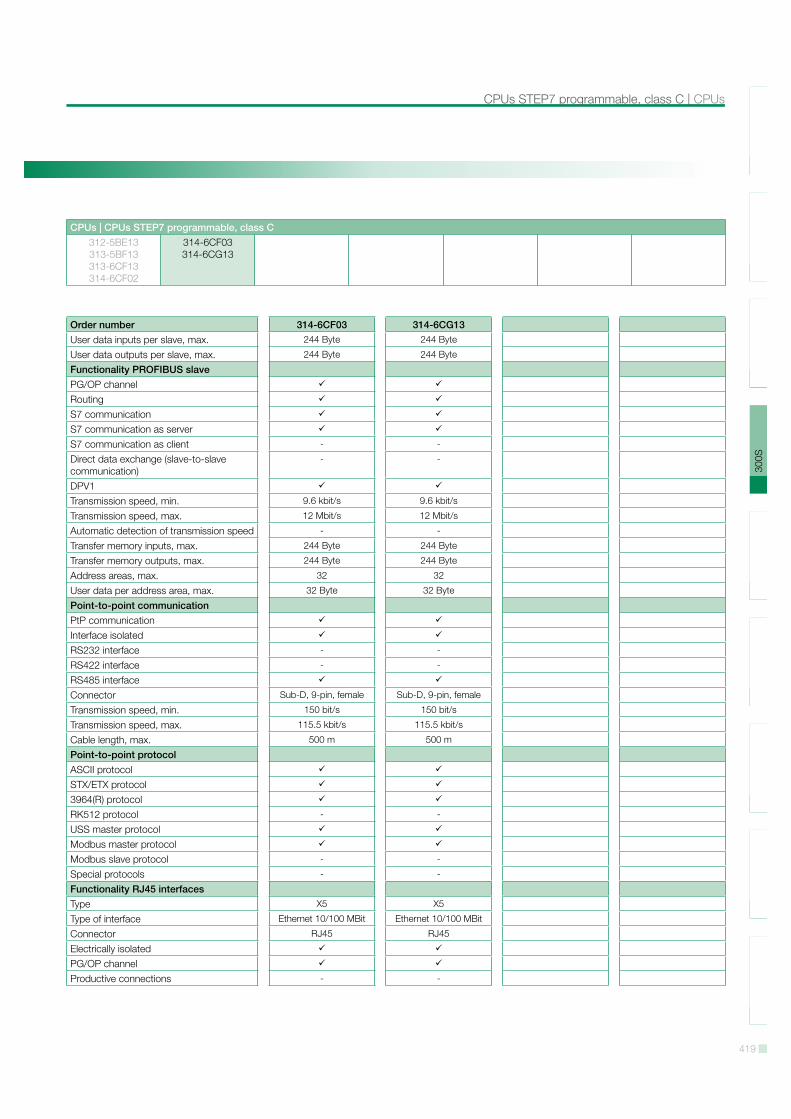
419
SLI
O10
0V20
0V30
0S50
0SH
MI
Sof
twar
eA
cces
sorie
sA
ppen
dix
CPUs STEP7 programmable, class C | CPUs
CPUs | CPUs STEP7 programmable, class C312-5BE13313-5BF13313-6CF13314-6CF02
314-6CF03314-6CG13
Order number 314-6CF03 314-6CG13User data inputs per slave, max. 244 Byte 244 Byte
User data outputs per slave, max. 244 Byte 244 Byte
Functionality PROFIBUS slavePG/OP channelRoutingS7 communicationS7 communication as serverS7 communication as client - -
Direct data exchange (slave-to-slave communication)
- -
DPV1Transmission speed, min. 9.6 kbit/s 9.6 kbit/s
Transmission speed, max. 12 Mbit/s 12 Mbit/s
Automatic detection of transmission speed - -
Transfer memory inputs, max. 244 Byte 244 Byte
Transfer memory outputs, max. 244 Byte 244 Byte
Address areas, max. 32 32
User data per address area, max. 32 Byte 32 Byte
Point-to-point communicationPtP communicationInterface isolatedRS232 interface - -
RS422 interface - -
RS485 interfaceConnector Sub-D, 9-pin, female Sub-D, 9-pin, female
Transmission speed, min. 150 bit/s 150 bit/s
Transmission speed, max. 115.5 kbit/s 115.5 kbit/s
Cable length, max. 500 m 500 m
Point-to-point protocolASCII protocolSTX/ETX protocol3964(R) protocolRK512 protocol - -
USS master protocolModbus master protocolModbus slave protocol - -
Special protocols - -
Functionality RJ45 interfacesType X5 X5
Type of interface Ethernet 10/100 MBit Ethernet 10/100 MBit
Connector RJ45 RJ45
Electrically isolatedPG/OP channelProductive connections - -
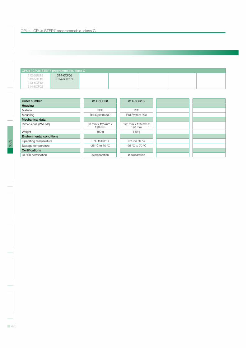
420
SLI
O10
0V20
0V30
0S50
0SH
MI
Sof
twar
eA
cces
sorie
sA
ppen
dix
CPUs | CPUs STEP7 programmable, class C
CPUs | CPUs STEP7 programmable, class C312-5BE13313-5BF13313-6CF13314-6CF02
314-6CF03314-6CG13
Order number 314-6CF03 314-6CG13HousingMaterial PPE PPE
Mounting Rail System 300 Rail System 300
Mechanical dataDimensions (WxHxD) 80 mm x 125 mm x
120 mm120 mm x 125 mm x
120 mm
Weight 480 g 610 g
Environmental conditionsOperating temperature 0 °C to 60 °C 0 °C to 60 °C
Storage temperature -25 °C to 70 °C -25 °C to 70 °C
CertificationsUL508 certification in preparation in preparation
421
SLI
O10
0V20
0V30
0S50
0SH
MI
Sof
twar
eA
cces
sorie
sA
ppen
dix
CPUs STEP7 programmable, class C | CPUs
CPUs | CPUs STEP7 programmable, class C312-5BE13313-5BF13313-6CF13314-6CF02
314-6CF03314-6CG13
Connections, Interfaces
314-6CF03
314-6CG13


![Company Profiles Vipa / Vipa Polimeri Page 1/18 profile Vipa... · Company Profiles Vipa / Vipa Polimeri Page 2/18 VIPA S.r.l. [beginnings]Vipa is a leading company in the field of](https://img.pdfslide.net/doc/110x75/5f5cfa7c6cc46b644e27ef7b/company-profiles-vipa-vipa-polimeri-page-118-profile-vipa-company-profiles.jpg)