Embed Size (px)
Citation preview

Int J Interact Des Manuf (2012) 6:131–137DOI 10.1007/s12008-012-0157-9
TECHNICAL PAPER
Virtual reality based safety system for airborne platforms
Paul Huang · Omar Khan
Received: 9 June 2011 / Accepted: 21 March 2012 / Published online: 21 April 2012© Springer-Verlag 2012
Abstract The ability to use computer generated high qual-ity real-time video provides engineers/scientists/electronicgame designers a powerful tool in many applications. Theadvent of micro-electronics further enables complicateddevices to be put into smaller, inexpensive, and robust pack-ages. During the last few years, smaller video-image-baseddevices have been installed in land-based vehicles to enhancedriving comfort, convenience, and safety. These include nav-igational aids, GPS, collision avoidance devices, and manyothers. The proliferation of these devices is mainly due tothe relatively inexpensive and short life span of land vehiclescompared to that of airplanes (and submarines). This paperreports the development of a pilot/driver aid that can be usedas an add-on to existing vehicles with minimal retrofit. Withthis device, pilots or drivers can operate the vehicles underextreme weather conditions when visual contact with the out-of-the-window view is not available. The implementation ofthis process is used not only for manned helicopters but alsoas a training aid for unmanned helicopter pilots.
Keywords Real-time · Computer generated video image ·Micro-electronics · Operator aid
1 Introduction
Due to the advancement of computer software and hardwaretechnology [1], near realistic computer-generated video canbe produced by relatively inexpensive computing platforms
P. Huang · O. Khan (B)Trident Corporation, 100 Canterbury Road, Circle Pines,MN 55014, USAe-mail: [email protected]
P. Huange-mail: [email protected]
in real-time [1,2]. Many consumer electronics adopt thesenew developments so that the general public can have betterand cheaper products. This trend has pushed for more newproducts to the market [3].
The fast tempo of technology advancement and the questfor introducing newer gadgets has propelled industries tolook into many areas that in the past had only been reservedfor special high value usage such as aerospace and defenseindustry applications. The large volume of demand from thegeneral public have helped to break down the high cost andsystem complexity barriers so that more people can bene-fit from those products which further accelerates develop-ment.
This demand/development cycle has helped the prolifer-ation of many commercial products that make human livesmore comfortable, interesting, convenient, and safer [3]. Forexample, the Global Position System (GPS) has helped manydrivers/pilots to reach their destination quickly and safely.Many of collision prevention devices have prevented andreduced traffic accidents substantially. Other than most pri-vate land passenger vehicles, the majority of transportationplatforms has long operating lives and cannot have theseupdated technology advantages easily added on due to theprohibitive cost of retrofitting and system integration. Thesetransportation platforms include, but are not limited to, var-ious aircraft (both fixed wing and rotary wing) and marinevehicles (both surface ships and submarines).
This paper reports the development and implementationof a pilot aid using virtual images so that when the out-of-the-window view is not available, the driver/pilot still canoperate the vehicle safely. A major constraint of this devel-opment is that the end result should be a modular systemthat can be installed and integrated on existing vehicles withminimal cost and effort. A portion of the results from the labtests also are included in this writing.
123

132 Int J Interact Des Manuf (2012) 6:131–137
2 Problem statement
Due to the increase in the global wealth, aircraft have becomea common form of transportation in every region of the world.With the advancement in weather forecast and better navi-gation technology, the safety operation of the aircrafts hasimproved significantly. However, two of the most dangerousmoments when operating an aircraft, namely take-off andlanding, still depend heavily on the skill of the pilots.
Although the cockpits may be equipped with advancedavionics, one of the most important factors for take-off orlanding is a clear out-of-the-window view which providesthe final details of the take-off or touchdown of the aircraft.The view provides the pilots the most critical factor to controlthe aircraft. In the past the need for the clear view for the pilothas been a major design factor for the aircraft, for exampleall the super sonic transporters (SSTs) were equipped withtillable nose cones so that during the landing process thepilot can look directly at the runway for touchdown. Theadding of the tillable nose cones created system complexityand substantial cost for the development of the SSTs but itwas absolutely a necessity then (Concorde Movable Nose-cone).
The weather and terrain conditions are two important fac-tors contributing the safe operation of the aircraft. Other thanmechanical problems, another main cause of aircraft acci-dents is poor weather and/or weather conditions. A study bythe U.S. Federal Aviation Administration (FAA) revealed thatover 20 percent of accidents in civilian aircraft occur due toweather related causes [4]. This number could be up to fourtimes higher for military aircraft according to experts fol-lowing the issue [5]. Unfortunately, many special situationsforce the pilots to operate the aircraft in extreme weatherand terrain conditions when clear out-of-window views arecompromised.
Dust and snow on the ground are two of the most commonfactors that can blind the views of pilots during takeoff andlanding. The air flows required to lift the aircraft unavoid-ably kick off the dust, sand, or snow which can form a heavyvisual barrier that, in turn, completely or partially impairsthe vision of the pilots. Under these conditions, the pilot,not only cannot see the ground but he or she may instantlylose orientation completely. According to the report [6] amajority of the non-combat related loss of helicopters in theAfghan war was due to the dust clouds, so called “brown-out”. Similarly, many aircrafts were forced to operate whenthe landing sites or runways were covered by snow. Thesnow covered landing sites would cause the condition called“whiteout”, that occurs when accumulated snow is kicked offby the lifting force of the propellers. In such cases the air-craft would be completely engulfed by the white dust whichis another one of the feared nightmares for experienced heli-copter pilots.
3 Proposed approaches
Sensor technology has improved significantly during thelast few decades. Precision, robustness, data fusion, and thedevelopment of standardized interfaces for sensors with otherdevices have given rise to a wider set of applications for thosesensors. The combination of sensor data with computer-gen-erated images can now provide the user with the ability torepresent data in different formats and enables a wider usageof sensory systems [7].
For the last few years, new applications, such as motioncapture and real-time generated environments/objects haveenabled the blending of “realities” (objects, environment,etc.) with “virtual” elements [8]. In the problem stated above,the missing piece for the safe landing and takeoff is the clearout-of-the-window view for the pilot. How to provide a use-able out-of-the-window view during a “whiteout” or “brown-out” condition using new applications is the purpose of thisresearch.
Instead of spending substantial amount of resources infinding an elaborated solution for this urgent need, the authorstried to provide a “quick fix” approach for this problem. Dueto the limited time and resources available from the time ofproof of concept initiation to lab tests, modeling and simu-lation and rapid prototyping methodology was used. Manysurrogate equipment/tools were used for the development ofthis approach. With the help of past experiences, the authorshave gained substantial confidence in this approach [8–10].Although it might be a “quick and dirty” approach, gen-eral engineering practices, especially real-time software andhardware development guidelines were followed rigorously[3,11].
Databases for the entire world’s terrain are updated almostconstantly and most of this data is widely available from theopen domain. Sources include the U.S. Geological Survey(USGS) that produces the GTOPO30, which is a global digi-tal elevation model (DEM) that covers worldwide locations.WebGIS is another source that produces 30 m by 30 m res-olution data. The use of terrain data in survey, training, andmany other applications is nothing new. Having access to thisdata provides a golden opportunity for solving the whiteoutand brownout problem stated above.
As shown by recent studies [4,5], one of the most serioussafety concerns for a pilot during flight is the landing of theaircraft in brownout or whiteout situations. This situation ispredominantly encountered by military helicopters, medicalevacuation (MEDEVAC) aircraft and emergency responsehelicopters as they constantly operate in non-standard andhazardous conditions outside of commercial flight regula-tions. Helicopter brownout is a US$100 million per yearproblem for the U.S. Military in Afghanistan and Iraq. TheArmy cites brownout as the cause of three out of every fourhelicopter accidents there [12]. Under whiteout or brownout,
123
Int J Interact Des Manuf (2012) 6:131–137 133
the out-of-the-window view may be completely blocked.This research used the case of landing a helicopter in a dustyfield in which a brownout had completely impaired the out-of-the-window view of the pilot to explain how the proposedsolution may work.
In the scenario under consideration, before the helicopterapproaches the final landing spot, for the first stage of thesafety system, the pilot uses a laser designator to select thecenter point of the landing site. In the mean time, the GPSsynchronizes the time and records the exact location of thehelicopter. The safety system will use the relative location ofthe helicopter and the landing site to generate the 3-D viewand dynamically present the view in real-time to assist thepilot in landing his craft.
Before the touchdown of the helicopter, the second stageof the safety system will start seamlessly and automati-cally. A set of remote sensing devices that are mounted nearthe bottom of the landing device will provide the orienta-tion and precise distances between the landing surface andthe exact landing points on the helicopter. In such man-ner, when the pilot, who is virtually blinded by the clouddust, can have all the detailed information to land the craftsafely.
At the third stage, the distances from each proposed land-ing gear are displayed for the pilot for final adjustment to levelthe helicopter. To minimize the training and familiarizationto use this device, the virtual view can be easily generatedand displayed on the heads-up display (HUD) of the pilot.With the aid of this device even though the pilot’s vision iscompletely blocked by the dust, functionally, the virtual viewis no different than the “real” view and provides him or herwith a clear but virtual out-of-the-window view to land thecraft as needed.
4 Computer-based hybrid simulation
The engineers conducted a hybrid computer simulation thatcombined video data with computer-generated views to testthe feasibility of the safety system. The snap shot of the land-ing site is shown in Fig. 1.
The pilot “selected” a landing site for his helicopter. Inhis view, in addition to the real out-of-the-window view, anicon and numerical data were overlaid on the same view toprovide him with landing information. The combined /aug-mented view is shown in Fig. 2.
To further enhance the visualization for the pilot, a com-puter-generated heliport icon was produced and overlaid onthe view. Also, the relative orientation of the heliport wasprovided by an arrow on the synthetic view for the pilot. Asthe helicopter approached the landing site, the safety systemprovided the synthetic view of the virtual heliport which wasoverlaid on the real-time view so that the pilot could land
Fig. 1 The snap shot from the video was captured for the hybridsimulation
Fig. 2 The added icon and numerical data provide the pilot with land-ing information (distance, orientation, etc.)
his craft on the virtual heliport (pre-selected site as shown inFig. 3.).
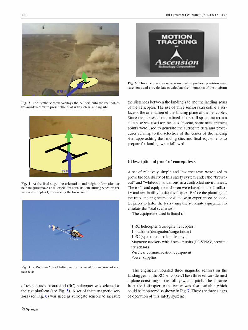
During the final stage of landing, data from the sensorsystem was used to provide the height and orientation of thecraft. An experienced pilot can use this visual informationfor final correction to ensure a smooth landing (Fig. 4).
5 Lab tests
A set of preliminary lab tests were derived after the hybridsimulation of this proposed approach. To conduct this set
123
134 Int J Interact Des Manuf (2012) 6:131–137
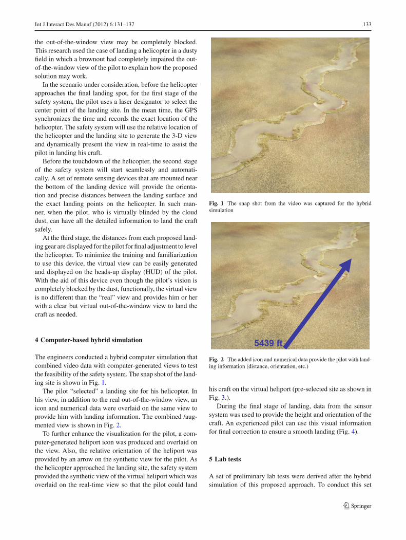
Fig. 3 The synthetic view overlays the heliport onto the real out-of-the-window view to present the pilot with a clear landing site
Fig. 4 At the final stage, the orientation and height information canhelp the pilot make final corrections for a smooth landing when his realvision is completely blocked by the brownout
Fig. 5 A Remote Control helicopter was selected for the proof-of-con-cept tests
of tests, a radio-controlled (RC) helicopter was selected asthe test platform (see Fig. 5). A set of three magnetic sen-sors (see Fig. 6) was used as surrogate sensors to measure
Fig. 6 Three magnetic sensors were used to perform precision mea-surements and provide data to calculate the orientation of the platform
the distances between the landing site and the landing gearsof the helicopter. The use of three sensors can define a sur-face or the orientation of the landing plane of the helicopter.Since the lab tests are confined to a small space, no terraindata base was used for the tests. Instead, some measurementpoints were used to generate the surrogate data and proce-dures relating to the selection of the center of the landingsite, approaching the landing site, and final adjustments toprepare for landing were followed.
6 Description of proof-of-concept tests
A set of relatively simple and low cost tests were used toprove the feasibility of this safety system under the “brown-out” and “whiteout” situations in a controlled environment.The tools and equipment chosen were based on the familiar-ity and availability to the developers. Before the planning ofthe tests, the engineers consulted with experienced helicop-ter pilots to tailor the tests using the surrogate equipment toemulate the “real scenarios”.
The equipment used is listed as:
1 RC helicopter (surrogate helicopter)1 platform (designator/range finder)1 PC (system controller, displays)Magnetic trackers with 3 sensor units (POS/NAV, proxim-ity sensors)Wireless communication equipmentPower supplies
The engineers mounted three magnetic sensors on thelanding gear of the RC helicopter. These three sensors defineda plane consisting of the roll, yaw, and pitch. The distancefrom the helicopter to the center was also available whichcould be monitored as shown in Fig. 7. There are three stagesof operation of this safety system:
123

Int J Interact Des Manuf (2012) 6:131–137 135
Fig. 7 The test uses a surrogate sensory system to create a syntheticheliport to assist landing
Stage 1: This is the normal operation of the helicopter, inwhich the vision of the pilot is completely “nor-mal”. At this stage, the pilot selects the center oflanding site and the safety system starts.
Stage 2: At this stage, after the pilot selected a landing siteand designated the center of the spot that the heli-copter should land at, the safety system startedproducing the “virtual view”. For the tests, this vir-tual view included the heliport, the distance fromthe heliport, and the rough order orientation of thehelicopter. Since this set of tests used a remotecontrol (RC) helicopter, an RC operator view isdisplayed. The virtual view and data are overlaidon the RC operator view to emulate the Heads updisplay (HUD) for the pilot.
Stage 3: At this stage the sensors mounted on the landinggear start providing the accurate measurement ofthe distances (and orientation) of the helicopter tothe pilot. The pilot can then adjust the orientationof the helicopter for a smooth landing.
For the tests, engineers used the real-time data that wassent back to the computer (through wireless communica-tions) from the sensory system to create a synthetic viewof the virtual “heliport” and display it on the screen of thePC. The operator of the helicopter (the surrogate pilot) usedthe displayed view to control and land the helicopter (insteadof plain vision from the helicopter). When the helicopter waswithin a certain distance from the “heliport”, in addition tothe synthetic heliport view, an additional “bird’s eye view”of the helicopter and the ground from any convenient anglewas available for the pilot. Several icons that showed thedistances (we picked three points; left front, right front, andback) from the landing skid to the ground were also displayed(shown in Fig. 8 as d2, d1, and d3).
Using this visual aid, the pilot could level the helicopterand land the plane safely and smoothly. Due to the power
Fig. 8 The added view can help the pilot to level the helicopter duringlanding
requirement, we kept the initial distance and height (d and hin Fig. 7) short. Since the results of this test depended heav-ily on the skill of the RC helicopter operator, the operator(pilot) had to be familiar with the skill to land and take offthe RC helicopter using the view from the computer displayinstead of staring at the helicopter directly. We recorded thelanding data with time stamps so that we could evaluate thetest results with less personal biased opinion.
7 User jury review and discussion
None of the developers had ever flown a helicopter and hencethe whole concept and tests needed to be reviewed thoroughlyby potential users. Three experienced helicopter pilots werechosen to serve as user jury for this task. Their suggestionsand critiques were collected and applied for these tests.
All the members of the user jury had experiences in eitherwhiteout or brownout situations. According to them, thissafety system can be a significant help for pilots. They scru-tinized the detail of the rationale of the selection of the equip-ment and thoroughly reviewed the procedures of the simula-tion and lab tests. To generate the plane for the definition ofthe orientation, more than three sensors should be used forredundancy.
According to them, this system should not add any extraburden to the pilots who will use it. Integration of the finalizedsystem into the helicopter heads-up display (HUD), however,should be taken up as a future work and as an extension to thisstudy. Different helicopters have different display systems.These display systems do not only vary from one make andmodel of the helicopter to another, but are also dependenton their main mission i.e. combat, surveillance or rescue etc.In all cases it should be ensured that the virtual view is cus-tomized and easily displayed on the HUD of the pilot. All ofthem asserted the importance of conducting a real-flight testin addition to the simulation and lab tests.
123

136 Int J Interact Des Manuf (2012) 6:131–137
8 Potential extensions
The blending of “real” view with computer-generated dataand/or virtual view is nothing new. Military and other spe-cial applications have used similar techniques for a long time.A wider application that allows the general public to enjoythe technology advancement, due to economic consideration,has been slow and limited in scope in the past.
Recent military applications where stealth and surgicalstrikes are required by helicopter crews; a nighttime landingin totally dark conditions can be achieved and safely imple-mented by adding on this system onto almost any combataircraft.
Most of the land vehicle drivers have experienced drivingin extreme weather conditions. Fog, rain, sleet, snow, duststorm, or other factors may block the vision of the drivers.Sometimes, the driver cannot see the road signs or even theroad. Under those situations, even well-paved road could notprovide any reference for the drivers. Many accidents hap-pen in those conditions. This safety system may have thepotential to solve the driving problems that are mentionedabove provided several issues can be resolved first.
The safety system stated above provides the driver (pilot)a synthetic real-time view using sensory data to emulate theenvironment. The display is on the HUD of the pilot and thehead movement is tracked constantly. The safety system usesthe relative location of the HUD to display the “exact” view.For the land vehicles, other than those special cases such ascombat vehicles, race cars, and those in heavy industry usage,the drivers, in general, do not wear any head gear or goggles.The only possible location for the display that will not inter-fere with the general driving habit is on the windshield. In thepast, some civilian vehicles have been equipped with HUDrelated technology that would display data such as speed,orientation, and the like. But no real viewing related data hasever been tried to display for non-military land vehicle.
The viewing angle for different drivers would be different.The demanding for the driver to sit and look at a fixed locationis absurd. “How to display the “correct” viewing angle for aspecific driver” is a very complicated problem. The trackingof the eyes of the driver is feasible but it adds substantialdifficulty to the safety system. The cost and complexity arealso beyond the scope of this research at this moment. It canbe a future research topic.
The taking-off and landing of an aircraft are two distinctand discrete processes that all the pilots have to concentrateon completely. During those processes, the pilot, most of thetime, can proceed slowly at his/her own pace while usingall the data available. A separate view that shows the rel-ative position of the helicopter and the virtual heliport canprovide the pilot needed data for fine adjustment for landingor takeoff. For the land vehicle users, it will be completelydifferent.
The driving of a land vehicle is a continuous process. It isvery difficult to demand complete concentration during theuse of the vehicles. To handle a sudden incident while drivingsuch as applying the break or turning the steering wheel, thedriver does not have time to look at any other direction thanthe exact out-of-the-window view. And the reaction fromthe driver must be instantaneously. The display of any otherview other than on the windshield can hardly help the driverto accommodate any sudden change and reaction. The dis-traction of the driver’s view can result in disaster.
The tracking and identification of people’s retina has beenused for user authorization and security purpose. The pro-cessing time duration and complexity have been improvedsignificantly lately. This may provide a useful tool to trackviewing angle of the driver in real-time. Similar techniqueshave been used in some areas such as robotic safety systems,among others. We anticipate more application of the blend-ing of virtual view with real-time view will be used in manydaily applications.
Another potential application area is for boats and ships.Under foggy weather, the system might provide the naviga-tors with a powerful tool to maneuver the crafts in treacheryor busy waterways. Most of the larger boats and ships arealready equipped with navigation aid but most small craftsdo not have those expensive navigation equipment or aids.Also, the casual users do not have the training for the useof complicated navigation equipment. A simple to use safesystem may provide many users with a viable tool to enhancethe safety of the casual users.
Acknowledgements The authors wish to thank vendors and col-leagues for their hard work, and support. Without their help the successof this project would not have been possible. The authors also wish tothank those helicopter pilots especially Major Paul Franken who haveprovided the authors with their precious experiences in those extremeweather conditions. They also gave their unreserved opinions to theauthors so that this research could be performed in the shortest possibletime and least resources.
References
1. DoD Directive 5000.59: Modeling and Simulation (M&S) Man-agement Definition (1994)
2. Huang, P.: A practitioner’s view of virtual prototyping. In: Pro-ceedings of Virtual Concept 2005, Biarritz (2005)
3. Sellers, J., Milton, E.: Technology for Reduced Cost Mission. Klu-wer, Boston (1996)
4. Federal Aviation Administration (FAA) Aviation Safety Informa-tion Analysis and Sharing (ASIAS): Weather Related-AviationAccident Study 2003–2007 (2010)
5. Whittle, R.: Army Seeks Brownout Fixes For Helo Pilots; AfghanTests Loom, 9 March 2012, AolDefense
6. Colucci, F.: ‘Sandblaster’ Gives Helicopter Pilots Hope for SaferLandings; National Defense, NDIA’s Business Magazine (2007)
7. Huang, P.: Sensor resolution question for flexible robot positioning,1987. Motion Control Conference
123

Int J Interact Des Manuf (2012) 6:131–137 137
8. Huang, P., Khan, O., Heim, D.: The use of virtual reality for sys-tem development: a case study. In: Proceedings of Virtual Concept,Biaritz (2003)
9. Huang, P., Holmes, C., Khan, O., French, S., Alexander, E.: Usingaugmented reality to develop a robotics safety system. In: Inter-service/Industry Training, Simulation, and Education Conference(I/ITSEC) 2009, Orlando (2009)
10. Huang, P., Kar, P., Kennedy, A., Kato, H.: System integration labo-ratory: a new approach to software/electronics system integration.In: Sixth Annual International Symposium, International Councilon Systems Engineering, Boston (1996)
11. Jaffe, M., Leveson, N., Heimdah, M., Melhar, B.: Software require-ments analysis for real-time process control system. IEEE Trans.Soft. Eng. 17(3), 241–258 (1991)
12. Sabbagh, L.: Flying Blind in Iraq: U.S. Helicopters Navigate RealDesert Storms. Popular Mechanics (2006)
123


![Movement Visualizer for Networked Virtual Reality Platforms · 2019. 2. 11. · Graphics] Three-Dimensional Graphics and Realism: Virtual Reality; K.8 [Personal Computing] Games 1](https://img.pdfslide.net/doc/110x75/5fe2537562cd910f580e1802/movement-visualizer-for-networked-virtual-reality-platforms-2019-2-11-graphics.jpg)