Embed Size (px)
Citation preview
1 SpeedTech Lights, Inc © 2019
RAPTOR®VISOR LIGHT BAR
B-RT10B-RL10
INSTRUCTION MANUAL

2 SpeedTech Lights, Inc © 2019
RAPTOR®VISOR LIGHT BAR
Warnings and Notices for Users and InstallersThis document must be delivered to and read by the end user and installer as it serves to provide you with the required information for proper and safe use of your STL product. Before operating this or any STL products the user and installer must read this manual all the way through. You will find important information in this manual that could prevent property damage and/or serious injury to the user and installer.
STL products are intended to alert pedestrians and other operators of the presence of personnel, the operation of emergency vehicles, an emergency site, and any warning needs. This does not ensure that pedestrians or drivers will react, heed, or observe emergency warning signals. Nor does the use of emergency signals grant or ensure you the right of way. It is your responsibility to make sure you can proceed safely before driving against traffic, entering an intersection, responding at a high rate of speed, or walking on or around traffic lanes.
Your STL emergency vehicle devices should be tested daily to ensure the device and all its functions are operating correctly. If you experience a malfunction contact STL’s Customer Service immediately for troubleshooting options, or a warranty or service claim. You must ensure that the projection of the visual and audible signal is not blocked by vehicle components (i.e.: open trunks, visors, compartment doors), vehicles, other obstructions, or people.
This is professional grade equipment and is intended for strict use by authorized personnel only. It is the user’s responsibility to understand and obey all laws regarding emergency warning devices. You must know and be familiar with all applicable city, state, and federal laws and regulations prior to the use of emergency vehicle warning devices.
SpeedTech Lights, Inc assumes no liability for any loss resulting from the use of this warning device. Proper installation is vital to the performance of the warning devices and safe operation of the emergency vehicle. Since the operator is under stressful environments the equipment must be properly wired and mounted to ensure effectiveness and safety. Therefore controllers must be properly installed and placed within convenient reach of the operator so eye contact with the roadway is never lost.
The effectiveness of your STL equipment is highly dependent upon correct mounting and wiring. Improper wiring and mounting of the warning device will reduce the output and performance of the equipment. Emergency warning devices frequently require high electrical voltages and/or currents. Properly protect and use caution around live electrical connections. Grounding or shorting of electrical connections can cause high current arcing, which can cause severe personal injury and/or serious vehicle damage, including fire.
Electromagnetic interference can be caused by many electronic devices used in emergency vehicles. To ensure that this doesn’t happen to you, Light Bars should be mounted a minimum of 12” - 34” from the radio antenna and do not power your equipment from the same circuit or share the same grounding circuit with radio communication equipment. After installation, test all the vehicle’s equipment together to ensure everything operates free of interference.
Driver and/or passenger airbags (SRS) will impact the way you mount your equipment. Any equipment installed in the deployment area of the airbags will damage or dislodge the airbags and sensors. This will also reduce the effectiveness of the airbags to protect the passengers and therefore these areas must be avoided. Installers must make sure that this equipment along with any parts, hardware, wiring, power supplies, and switch boxes do not interfere with the airbags, SRS wiring, or sensors.
All STL equipment needs to be mounted and installed according to the vehicle manufacturer’s instructions and securely attached to a part of the vehicle of sufficient strength to withstand the forces applied by the equipment. This device should be permanently mounted within the zones specified by the vehicle manufacturer. This especially applies to equipment mounted on the exterior of the vehicle to avoid dislodging. Mounting units on the interior of the vehicle by a method other than permanent mount is discouraged as it may become detached under aggressive driving conditions such as sudden braking, collision, or swerving.
PROPER INSTALLATION COMBINED WITH OPERATOR TRAINING IN THE PROPER USE OF EMERGENCY WARNING DEVICES IS ESSENTIAL TO ENSURE THE SAFETY OF EMERGENCY PERSONNEL AND THE PUBLIC.
Unpacking Your STL Product • Unpack your unit to identify all parts including but not limited to: Light Bar, switch box, brackets, screws, bolts, wiring harness, fuses, etc. • Some parts may be in small bags. • Some products may be packaged inside boxes of other products. • Some parts such as Gutter Brackets, may be in the foam protection. Double check that no parts are left within the foam protection or left in the box.
3 SpeedTech Lights, Inc © 2019
RAPTOR®VISOR LIGHT BAR
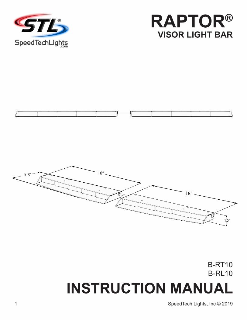
Important Points for Your Safety and Longevity of Your Light Bar• Installers are required to have a good understanding of automotive electronic systems and procedures for proper installation. • Never stare directly into the LEDs as momentary blindness and/or eye damage may occur.• Never take any lights through a car wash. Use only water to clean the outer body/lens of your equipment.• Never use a pressure washer to clean any STL products. Inspect and test your product daily to ensure it operates properly and is mounted
correctly.• Never cut wires or work on a unit while the unit is still connected to a power source.• Never install this product or route any wires through or in the deployment area of the airbag. Doing so may cause serious personal injury as it will
damage or reduce the effectiveness of the airbag by causing the unit to become a projectile. Reference the owner’s manual for your vehicle to find the airbag deployment area. The User/Installer assumes all responsibility to determine proper mounting location, based on providing ultimate safety to all passengers in the vehicle.
• If the product requires you to drill holes, the installer must ensure that the drilling process does not damage any vehicle components or other vital parts. Check all sides of the mounting surface before beginning to drill. Make sure to deburr all drilled holes and remove any metal remnants or shards to avoid injury and wires from becoming spliced. Grommets are to be installed in all wire passage holes.
• Grommets, cable ties, looms, and other installation hardware should be used to anchor and protect all wiring. Fuses should be properly sized and located as close to the power take off points as possible to protect the wiring and device. To protect against short circuits, a fuse is included by STL for all products. DO NOT use a fuse with a higher amp rating than the initial fuse included by STL for all products.
• Insulation displacement connectors are not to be used. • In order for STL products to operate at optimum efficiency, a secure and good electrical connection to the battery’s Ground Post must be made. The
recommended procedure requires the unit’s ground wire be connected directly to the NEGATIVE (-) battery post. DO NOT use Circuit Breaks.• Instruction manuals should be stored in a safe place for reference if you need to reinstall the unit or perform maintenance. They can also be
found at the main site under the product listing at www.SpeedTechLights.com. If your product is no longer available on the website contact STL’s Customer Service at 800-757-2581 for assistance.
• If your product requires the use of a control box or remote device to turn on and control your equipment, make sure it is installed in a location that allows both the user and the vehicle to operate safely in any driving condition.
• Never activate or control your equipment in hazardous driving conditions.• Use SXL type wire in the engine compartment where higher heat resistance is required according to SAE J-1128. All wires should be in accordance
with the minimum wire size and other recommendations made by the manufacturer and be protected from hot surfaces and moving parts.• FAILURE TO FOLLOW THESE SAFETY PRECAUTIONS, WARNINGS, NOTICES, AND INSTRUCTIONS COULD RESULT IN DAMAGE TO THE
PRODUCT OR VEHICLE THAT WILL VOID YOUR WARRANTY AND/OR CAUSE SERIOUS INJURY TO YOU AND YOUR PASSENGER.
Pre-Installation and TestingBENCH TEST all units prior to installation by connecting the Positive Cable (Red) and Negative Cable (Black) to a power source to ensure all the features and parts of the Light Bar are functional.
Test Check List:• LED diode and LED Module functionality• Flash patterns• Non-volatile memory• Physical damage
If you have trouble call Customer Service at 800-757-2581 before proceeding.
MaintenanceWhile STL’s Light Bars are very durable, there are some things you need to keep in mind and practice to preserve the longevity and function of your Bar.
• Never take any STL Light Bars through a car wash, such as a pressure washer, automatic car wash, brushes that will scratch your equipment or similar car washes or equipment where chemicals, high pressure water, and materials may scratch or damage your equipment.
• Use Water (H2O) with a soft cloth to clean your Light Bar and lenses.• Yellowing of clear lenses may occur overtime. Lenses can be purchased by calling STL Customer Service at 800-757-2581.
4 SpeedTech Lights, Inc © 2019
RAPTOR®VISOR LIGHT BAR
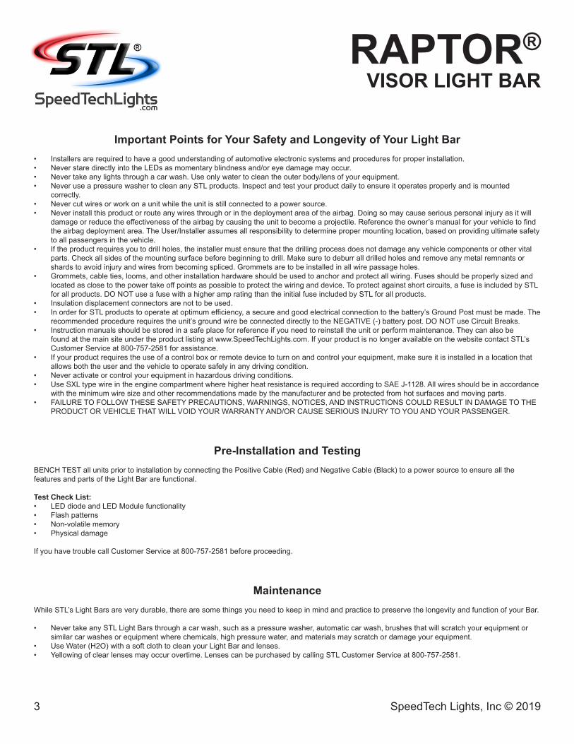
Grand Control Switch Box Operation (Sold Separately)Power Button:• Toggle to power the Light Bar On and Off.Flash Pattern Button:• Toggle button to cycle to the next flash pattern with each press. • Non-Volatile memory recalls the last flash pattern selected.• Hold for 3 seconds to toggle Steady Burn mode.• Hold for 5 seconds to toggle Random pattern mode.TD Button*:• 1st press: Steady Burn.• 2nd press: Flashing.• 3rd press: Flash in the same sequence/flash as the active warning pattern.AUX Button*:• Toggle power to AUX cables On and Off.Back Plate Mount:• Included with Grand Control Switch Box purchase.
* Warning lights do not need to be activated for these Buttons to function.
Extension Cable (Sold Separately)• If you have an extension cable with connectors, connect the corresponding ends to one another.
Use the connector at the end of the cable to plug into the control box.• If you have an extension cable with one connector, you will need to cut the connector off of the main
cable harness coming out of the Light Bar. Save it as a spare part. You will solder and heat shrink each wire within the cable harness to each wire in the extension cable harness. DO NOT cross connect wires. Use the connector at the end of the extension cable to plug into the control box.
• If you have an extension cable with no connectors, you will need to cut in the middle of the main cable harness coming out of the Light Bar. You will solder and heat shrink each wire within the cable harness to each wire in the extension cable harness. DO NOT cross connect wires. Use the reattached connector from the end of the main cable harness to plug into the control box.
• NOTE: DO NOT leave connectors, cables, solder points exposed to heat, moisture, or debris.
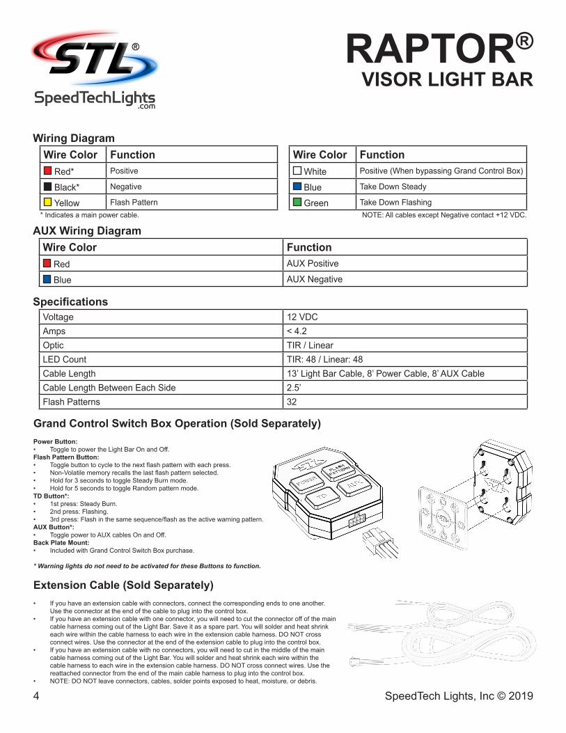
Wiring DiagramWire Color Function
Red* Positive
Black* Negative
Yellow Flash Pattern * Indicates a main power cable.
Wire Color Function White Positive (When bypassing Grand Control Box)
Blue Take Down Steady
Green Take Down Flashing NOTE: All cables except Negative contact +12 VDC.
SpecificationsVoltage 12 VDCAmps < 4.2Optic TIR / LinearLED Count TIR: 48 / Linear: 48Cable Length 13’ Light Bar Cable, 8’ Power Cable, 8’ AUX CableCable Length Between Each Side 2.5’Flash Patterns 32
AUX Wiring DiagramWire Color Function
Red AUX Positive
Blue AUX Negative
5 SpeedTech Lights, Inc © 2019
RAPTOR®VISOR LIGHT BAR
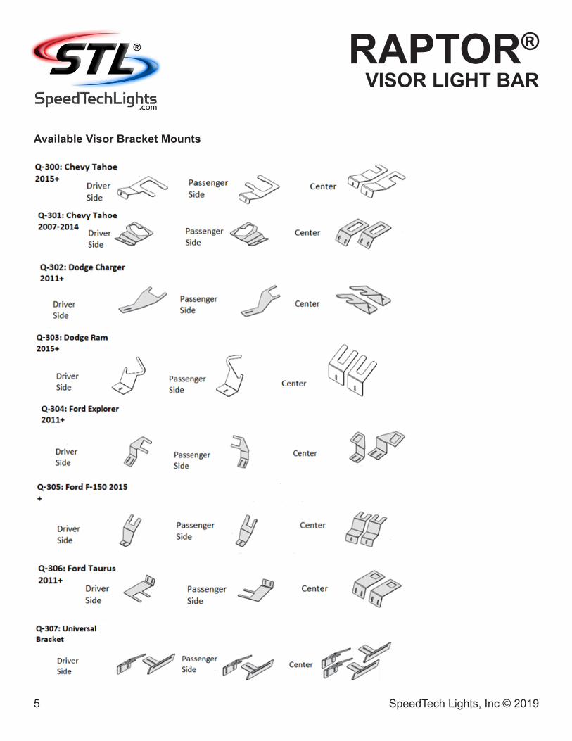
Available Visor Bracket Mounts
6 SpeedTech Lights, Inc © 2019
RAPTOR®VISOR LIGHT BAR
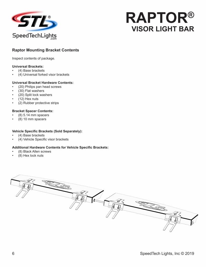
Raptor Mounting Bracket Contents
Inspect contents of package.
Universal Brackets:• (4) Base brackets• (4) Universal forked visor brackets
Universal Bracket Hardware Contents:• (20) Philips pan head screws• (30) Flat washers• (20) Split lock washers• (12) Hex nuts• (2) Rubber protective strips
Bracket Spacer Contents:• (8) 5.14 mm spacers• (8) 10 mm spacers
Vehicle Specific Brackets (Sold Separately):• (4) Base brackets• (4) Vehicle Specific visor brackets
Additional Hardware Contents for Vehicle Specific Brackets:• (8) Black Allen screws• (8) Hex lock nuts
Base Bracket
Visor Bracket
7 SpeedTech Lights, Inc © 2019
RAPTOR®VISOR LIGHT BAR
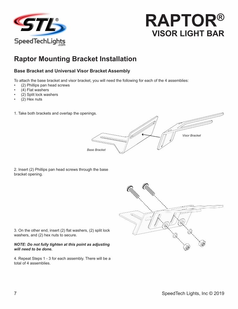
Raptor Mounting Bracket InstallationBase Bracket and Universal Visor Bracket Assembly
To attach the base bracket and visor bracket, you will need the following for each of the 4 assemblies:• (2) Phillips pan head screws• (4) Flat washers• (2) Split lock washers• (2) Hex nuts
1. Take both brackets and overlap the openings.
2. Insert (2) Phillips pan head screws through the base bracket opening.
3. On the other end, insert (2) flat washers, (2) split lock washers, and (2) hex nuts to secure.
NOTE: Do not fully tighten at this point as adjusting will need to be done.
4. Repeat Steps 1 - 3 for each assembly. There will be a total of 4 assemblies.
8 SpeedTech Lights, Inc © 2019
RAPTOR®VISOR LIGHT BAR
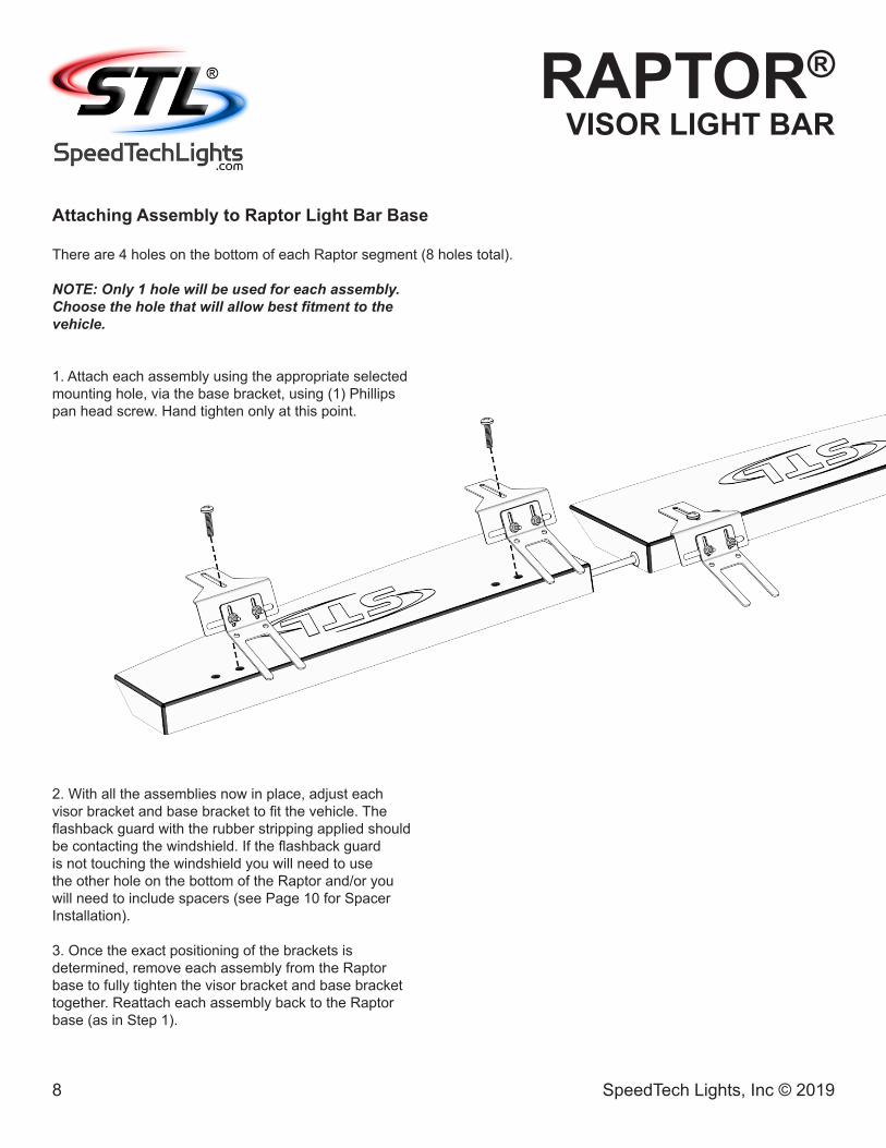
Attaching Assembly to Raptor Light Bar Base
There are 4 holes on the bottom of each Raptor segment (8 holes total).
NOTE: Only 1 hole will be used for each assembly. Choose the hole that will allow best fitment to the vehicle.
1. Attach each assembly using the appropriate selected mounting hole, via the base bracket, using (1) Phillips pan head screw. Hand tighten only at this point.
2. With all the assemblies now in place, adjust each visor bracket and base bracket to fit the vehicle. The flashback guard with the rubber stripping applied should be contacting the windshield. If the flashback guard is not touching the windshield you will need to use the other hole on the bottom of the Raptor and/or you will need to include spacers (see Page 10 for Spacer Installation).
3. Once the exact positioning of the brackets is determined, remove each assembly from the Raptor base to fully tighten the visor bracket and base bracket together. Reattach each assembly back to the Raptor base (as in Step 1).
Center Center Passenger SideDriver Side
9 SpeedTech Lights, Inc © 2019
RAPTOR®VISOR LIGHT BAR
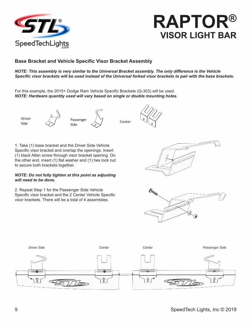
Base Bracket and Vehicle Specific Visor Bracket Assembly
NOTE: This assembly is very similar to the Universal Bracket assembly. The only difference is the Vehicle Specific visor brackets will be used instead of the Universal forked visor brackets to pair with the base brackets.
For this example, the 2015+ Dodge Ram Vehicle Specific Brackets (Q-303) will be used.NOTE: Hardware quantity used will vary based on single or double mounting holes.
1. Take (1) base bracket and the Driver Side Vehicle Specific visor bracket and overlap the openings. Insert (1) black Allen screw through visor bracket opening. On the other end, insert (1) flat washer and (1) hex lock nut to secure both brackets together.
NOTE: Do not fully tighten at this point as adjusting will need to be done.
2. Repeat Step 1 for the Passenger Side Vehicle Specific visor bracket and the 2 Center Vehicle Specific visor brackets. There will be a total of 4 assemblies.
10 SpeedTech Lights, Inc © 2019
RAPTOR®VISOR LIGHT BAR
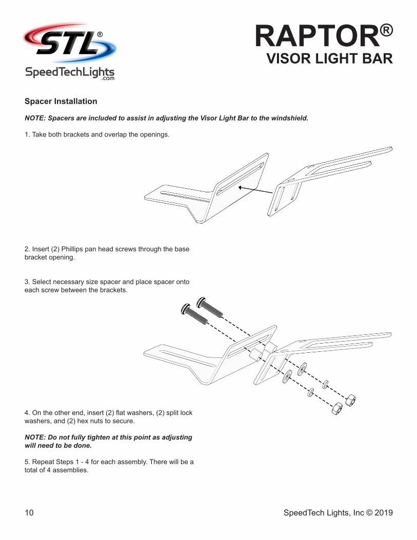
Spacer Installation
NOTE: Spacers are included to assist in adjusting the Visor Light Bar to the windshield.
1. Take both brackets and overlap the openings.
2. Insert (2) Phillips pan head screws through the base bracket opening.
3. Select necessary size spacer and place spacer onto each screw between the brackets.
4. On the other end, insert (2) flat washers, (2) split lock washers, and (2) hex nuts to secure.
NOTE: Do not fully tighten at this point as adjusting will need to be done.
5. Repeat Steps 1 - 4 for each assembly. There will be a total of 4 assemblies.
11 SpeedTech Lights, Inc © 2019
RAPTOR®VISOR LIGHT BAR
All rights reserved. No part of this Instruction Manual may be reproduced, distributed, transmitted, or otherwise shared in any form or by any means, including but not limited to photocopying, recording, electronic delivery, .PDF reproduction, or any other means of reproducing all or any part hereof without the express prior written consent of SpeedTech Lights, Inc, except for non-commercial purposes as permitted by United States copyright law. Customers of SpeedTech Lights, Inc, may download and print this Instruction Manual for use with products sold to the customer by SpeedTech Lights, Inc. However, no part of this Instruction Manual may be otherwise or subsequently reproduced, downloaded, disseminated, published, or transferred, in any form or by any means, except with the prior written consent of SpeedTech Lights, Inc.
Flash Pattern List• Steady Burn• Steady Burn Left Side. Quad Flash Right Side 120 FPM• Steady Burn Right Side. Quad Flash Left Side 120 FPM• Double Flash Alternating 180 FPM• Double Flash Front/Back 210 FPM• Triple Flash 75 FPM• Double Flash Left/Right 210 FPM• Double Flash 2 In/2 Out• Double Flash Alternating• Quad Flash 60 FPM• Quad Flash 90 FPM• Single Flash Left/Right 210 FPM• Back to Front Sweep• Single Flash Alternating 120 FPM• Single Flash 75 FPM• Single Flash 60 FPM• Single Flash 150 FPM• Single Flash Alternating 300 FPM• Single Flash Alternating 270 FPM• Single Flash 180 FPM• Single Flash 90 FPM• Variable Speed Left/Right• Slow Back to Front Sweep• Variable Speed Alternating• Variable Speed• Left/Right Double Time• Clockwise/Counter Clockwise Sweep• Clockwise Sweep• Counter Clockwise Sweep• Fast Clockwise Sweep• Fast Counter Clockwise Sweep• Random
Flash Pattern Shortcuts• Hold for 3 seconds to toggle Steady Burn mode.• Hold for 5 seconds to toggle Random pattern mode.
About Flash Patterns• All STL LED products are equipped with a non-volatile memory which will recall the last flash pattern when the Light Bar is turned on. • Set the flash pattern by pushing the Flash Pattern button on the Grand Control Box to cycle through the various patterns.• If you are not using the Grand Control Box, follow the wiring diagram to identify the Flash Pattern wire to manually cycle through patterns.