Embed Size (px)
Citation preview


I
Master of Science Programme in Medialogy
Master’s Thesis
Title: Real-Time Augmented Reality for Robotic-Assisted Surgery
Author:
_______________________ Martin Kibsgaard Jørgensen
Super visor: Martin Kraus
Abstract:
I try to improve communication during training with the da Vinci robotic surgery system, by allowing
a trainer to visually communicate with a trainee by augmenting the stereoscopic video stream.
I have investigated the video hardware of the da Vinci systems and implemented a system that is able
to input, output and overlay video streams compatible with all the systems. Additionally, I added
support for multiple 3D user input devices.
As an initial test and an example of how to use the developed system, virtual instruments have been
added to the system. In the test, the virtual instruments were overlaid the stereoscopic video stream of
the da Vinci S system in real-time.
Data: 26 August 2014
Pages: 52
Copies: 4
Copyright@2014. This report and/or app ended material may not be partly or completely published
or copied without prior written approval from the authors. Neither may the contents be used for
commercial purposes without this written approval.

II
III
Contents
1 Motivation ...................................................................................................................................... 1
1.1 Improving Training ................................................................................................................ 1
2 Hardware Environment .................................................................................................................. 5
2.1 Detecting Video Formats ........................................................................................................ 5
2.2 The da Vinci systems.............................................................................................................. 6
2.2.1 da Vinci .......................................................................................................................... 7
2.2.2 da Vinci S ....................................................................................................................... 9
2.2.3 da Vinci Si .................................................................................................................... 12
2.2.4 da Vinci Xi ................................................................................................................... 14
2.2.5 Summary....................................................................................................................... 15
2.3 YCbCr 4:2:2 ......................................................................................................................... 16
2.4 Hardware requirements ........................................................................................................ 16
3 System description........................................................................................................................ 19
3.1 Video Hardware.................................................................................................................... 19
3.1.1 Compatibility problems ................................................................................................ 19
3.2 User Input Devices ............................................................................................................... 20
3.3 Software ................................................................................................................................ 20
3.3.1 DeckLink API in Unity ................................................................................................ 21
3.3.2 Outputting video ........................................................................................................... 22
3.3.3 Keying .......................................................................................................................... 23
3.3.4 Inputting video.............................................................................................................. 23
3.3.5 Input devices ................................................................................................................. 24
3.3.6 da Vinci prefabs ............................................................................................................ 24
4 System test .................................................................................................................................... 27
4.1 Optimization ......................................................................................................................... 27
4.2 Performance tests.................................................................................................................. 27
4.3 Latency test ........................................................................................................................... 28
5 User evaluation ............................................................................................................................. 31
6 Conclusion .................................................................................................................................... 35
7 Future work .................................................................................................................................. 37
8 Bibliography ................................................................................................................................. 39
Appendix A. DeckLink API in Visual Studio ...................................................................................... 41
Appendix B. DVD ................................................................................................................................ 42

IV

V
READING GUIDE
References are cited using Chicago-style , e.g. (Last name 2014) and (Company 2014). A full list of
references can be found in Chapter 8 on page 39.
In this context:
- Surgeon always refers to a surgeon with expertise in robotic-assisted surgery.
- Trainer always refers to a surgeon or a nurse who teaches robotic-assisted surgery.
- Trainee is a medical student or surgeon that is currently learning robotic-assisted surgery.
- User always refers to an end-user, e.g. trainer and trainee.
- Developer always refers to a developer who utilizes the developed system, e.g. for future work.
In Appendix B on the last page there is a DVD attached, which includes this report in pdf format,
electronic sources, an A/V-production, different builds, and source code.
It can be beneficial to watch the A/V production before reading the report.
Enjoy
ACKNOWLEDGEMENT
I would like to thank Martin Kraus for his guidance, support, and great ideas, not only for this project,
but also all the way through my Master’s programme.
I wish to acknowledge the help and equipment made available by Aalborg University Hospital, and
especially thank Jane Petersson for all her help and sharing of expertise on the area of robotic surgery.

VI
Page 1 of 42
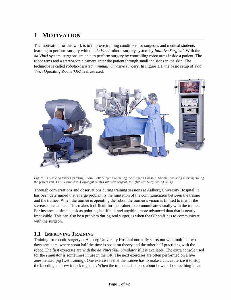
1 MOTIVATION
The motivation for this work is to improve training conditions for surgeons and medical students
learning to perform surgery with the da Vinci robotic surgery system by Intuitive Surgical. With the
da Vinci system, surgeons are able to perform surgery by controlling robot arms inside a patient. The
robot arms and a stereoscopic camera enter the patient through small incisions in the skin. The
technique is called robotic-assisted minimally invasive surgery. In Figure 1.1, the basic setup of a da
Vinci Operating Room (OR) is illustrated.
Figure 1.1 Basic da Vinci Operating Room. Left: Surgeon operating the Surgeon Console. Middle: Assisting nurse operating
the patient cart. Left: Vision cart. Copyright ©2014 Intuitive Srigcal, Inc. (Intutive Surgical (A) 2014)
Through conversations and observations during training sessions at Aalborg University Hospital, it
has been determined that a large problem is the limitation of the communication between the trainer
and the trainee. When the trainee is operating the robot, the trainee’s vision is limited to that of the
stereoscopic camera. This makes it difficult for the trainer to communicate visually with the trainee.
For instance, a simple task as pointing is difficult and anything more advanced than that is nearly
impossible. This can also be a problem during real surgeries when the OR staff has to communicate
with the surgeon.
1.1 IMPROVING TRAINING Training for robotic surgery at Aalborg University Hospital normally starts out with multiple two
days seminars; where about half the time is spent on theory and the other half practicing with the
robot. The first exercises are with the da Vinci Skill Simulator if it is available. The extra console used
for the simulator is sometimes in use in the OR. The next exercises are often performed on a live
anesthetized pig (wet training). One exercise is that the trainee has to make a cut, cauterize it to stop
the bleeding and sew it back together. When the trainee is in doubt about how to do something it can

Page 2 of 42
be difficult for the trainer to show it. If the trainee has to look at the trainer, the trainee has to lean
back, which locks the system.
Telestration is currently the only way to communicate visually with the surgeon at the console. It
allows the assisting surgeon and nurses, or in this case the trainer, to draw illustrations on a touch
screen visible in the surgeon’s console.
Figure 1.2 Left: Drawing around a pen on the touch screen. Right: The drawing is not placed at the correct depth on the
console and is wrongly positioned on both eye.
A problem with telestration is that the 2D drawing on the touchscreen does not translate easily to 3D
(Lamprecht, Nowlin og Stern 2011), which makes it imprecise and limits the situations where
telestration is usable. It is sufficient to mark a larger area, but not precise enough to point to for
instance a vein (see Figure 1.2). In 2005, Intuitive Surgical was granted a patent with several ideas on
how to improve telestration (Lamprecht, Nowlin og Stern 2011). I have not been able to find any
mentions of it being improved.
(Ali, Loggins og Fuller 2008) has successfully implemented and evaluated a 3D telestration system
for the da Vinci system. They did not find any significant difference in error rates between 2D and 3D
telestration, but also suggest further evaluations to be made due to a small sample size (three test
subjects). The system grabs the camera input (S-Video) and overlays the telestration on a computer.
The image is then output as VGA, converted back to S-Video, and used as input for the synchronizer
on the first generation da Vinci system (see Section 2.2.1). They claim the telestration appears on the
console immediately, but I assume the multiple conversions between analog and digital adds delay to
the original camera input. The setup is very similar to that of (Galsgaard, et al. 2014), who had
problems with latency.
(Galsgaard, et al. 2014) suggests that it might help to add virtual instruments to the display of the
console. It was difficult to prove as the latency of the proposed system was too high and made
controlling the robot difficult. They suggest using a hardware keyer, e.g. a BlackMagic Design
DeckLink card, to reduce the latency of the system.
To my knowledge, only (Ali, Loggins og Fuller 2008) and (Galsgaard, et al. 2014) have overlaid
graphics directly on the main video stream, and both targeted the first generations system.
Pre-recorded video is another way to show the trainee what to do. Either showing a clip in full screen
or in part of the console’s display would help the trainee with predictable problems. The newer da
Vinci systems already support showing additional video input using the TilePro-feature. TilePro

Page 3 of 42
allows the surgeon to display up to two additional video inputs in part of the console’s screens (see
Figure 1.3).
Figure 1.3 TilePro activated on the da Vinci S system. The size of the main video is reduced to make space for additional
video inputs. Copyright ©2014 Intuitive Srigcal, Inc. (Intutive Surgical (A) 2014)
It requires activating a device that outputs the video clip and enabling TilePro on the console. The
TilePro-feature shrinks the camera input and takes up the entire bottom of the display in the console
even when the TilePro input only takes up a small part of the width. It would be beneficial to have a
system that can overlay video without taking up as much of the screen space and without having to
activate the TilePro-feature manually.
The da Vinci Si and da Vinci Xi systems both support dual consoles, which enables two surgeons to
operate the (up to) three instruments on the same system. The extra console can also be used to draw
arrows that are visible on the other console. This is often used at Aalborg University Hospital when a
senior surgeon is supervising another surgeon during a surgery. As an extra console is expensive, I
assume a system that is able to draw the same (and more) is preferable for most training scenarios.
Overall, the equipment is expensive and limited and the need for wet training makes training
expensive. Improving communication capabilities during training could make training more efficient.
In addition to augmenting the video signal by showing drawings, virtual tools, videos, or images, a
solution to the communication problem might be to display a webcam stream of the trainer to the
trainee.
Due to the limited time available for this project (4 months) and the project overlapping with the
regular summer holiday (no seminars at Aalborg University Hospital), it is not feasible to evaluate
any of the suggested solutions sufficiently. For those reasons, I have decided to focus on investigating
the video hardware of the different da Vinci systems for future reference and develop a system that is
able to augment the video of those. The system has to be is easy to use and build upon for future
work.
The system should support the video signals from the different da Vinci systems and should both be
able to output, overlay and input the video signals. Input could be needed for calculating a disparity
map to know at which depth drawing should be placed (Ali, Loggins og Fuller 2008). Additionally, it
should support common input devices for 3D user input that can be used for e.g. controlling virtual
tools or drawing in 3D.

Page 4 of 42
Page 5 of 42
2 HARDWARE ENVIRONMENT
Before it is possible to develop a video augmenting system for the da Vinci systems, it is necessary to
investigate the video hardware of the system. This chapter will explain my approach and describe the
video hardware in detail.
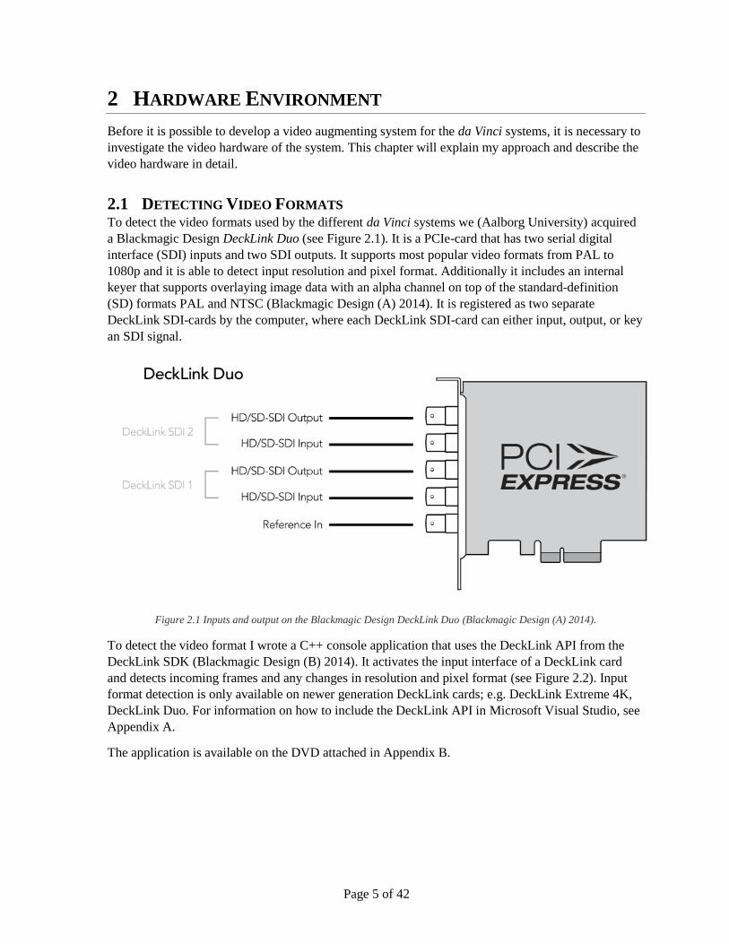
2.1 DETECTING VIDEO FORMATS To detect the video formats used by the different da Vinci systems we (Aalborg University) acquired
a Blackmagic Design DeckLink Duo (see Figure 2.1). It is a PCIe-card that has two serial digital
interface (SDI) inputs and two SDI outputs. It supports most popular video formats from PAL to
1080p and it is able to detect input resolution and pixel format. Additionally it includes an internal
keyer that supports overlaying image data with an alpha channel on top of the standard-definition
(SD) formats PAL and NTSC (Blackmagic Design (A) 2014). It is registered as two separate
DeckLink SDI-cards by the computer, where each DeckLink SDI-card can either input, output, or key
an SDI signal.
Figure 2.1 Inputs and output on the Blackmagic Design DeckLink Duo (Blackmagic Design (A) 2014).
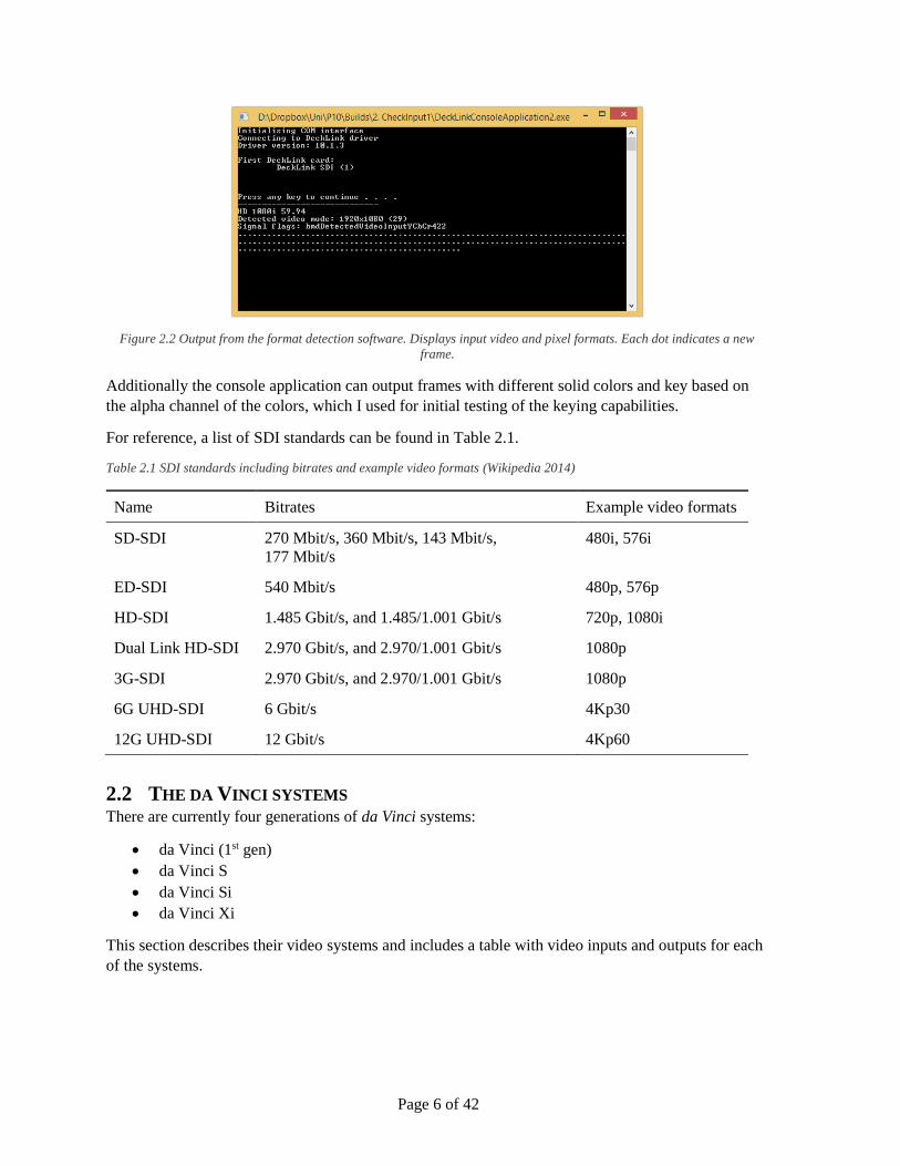
To detect the video format I wrote a C++ console application that uses the DeckLink API from the
DeckLink SDK (Blackmagic Design (B) 2014). It activates the input interface of a DeckLink card
and detects incoming frames and any changes in resolution and pixel format (see Figure 2.2). Input
format detection is only available on newer generation DeckLink cards; e.g. DeckLink Extreme 4K,
DeckLink Duo. For information on how to include the DeckLink API in Microsoft Visual Studio, see
Appendix A.
The application is available on the DVD attached in Appendix B.
Page 6 of 42
Figure 2.2 Output from the format detection software. Displays input video and pixel formats. Each dot indicates a new
frame.
Additionally the console application can output frames with different solid colors and key based on
the alpha channel of the colors, which I used for initial testing of the keying capabilities.
For reference, a list of SDI standards can be found in Table 2.1.
Table 2.1 SDI standards including bitrates and example video formats (Wikipedia 2014)
Name Bitrates Example video formats
SD-SDI 270 Mbit/s, 360 Mbit/s, 143 Mbit/s,
177 Mbit/s
480i, 576i
ED-SDI 540 Mbit/s 480p, 576p
HD-SDI 1.485 Gbit/s, and 1.485/1.001 Gbit/s 720p, 1080i
Dual Link HD-SDI 2.970 Gbit/s, and 2.970/1.001 Gbit/s 1080p
3G-SDI 2.970 Gbit/s, and 2.970/1.001 Gbit/s 1080p
6G UHD-SDI 6 Gbit/s 4Kp30
12G UHD-SDI 12 Gbit/s 4Kp60
2.2 THE DA VINCI SYSTEMS There are currently four generations of da Vinci systems:
da Vinci (1st gen)
da Vinci S
da Vinci Si
da Vinci Xi
This section describes their video systems and includes a table with video inputs and outputs for each
of the systems.

Page 7 of 42
2.2.1 da Vinci
Figure 2.3 The first generation da Vinci system. Copyright ©2014 Intuitive Srigcal, Inc. (Intutive Surgical (A) 2014)
Figure 2.3 shows the first generation da Vinci system, which Intuitive Surgical launched in 1999
(Intutive Surgical (A) 2014). Aalborg University currently has one first generation system in a
robotics laboratory for research purposes. The system has a two channel stereoscopic camera
(endoscope) that is connected to two camera controllers (for left and right eye), which amplify and
adjust the images. The camera controllers have multiple video outputs, where the output used in the
first generation system is S-Video. S-Video is an analog video signal also often labeled as Y/C.
Both outputs from the two camera controllers go into a synchronizer that synchronizes and converts
the two signals to digital SD-SDI. The format detection software (see Section 2.1) detects the video
format as PALi50, which has a resolution of 720 by 576 pixels refreshing at 50 fields per second. It is
an interlaced format, which means that only every second vertical line is updated each field. It detects
the pixel format to be YCbCr 4:2:2.
Figure 2.4 Left: Synchronizer at the bottom of the vision cart. Right: DeckLink Duo between the vision cart and the surgeon
console.
The SD-SDI signals are connected to the surgeon’s console via BNC-cables (see Figure 2.4). To
avoid conversions between analog and digital video, any analog video processing should be done
before the synchronizer, while digital video processing should be done after it. The console outputs
one channel that includes icons and text overlaid by the console. A monitor displays the output from
the console to the assisting surgeons and nurses.
Page 8 of 42
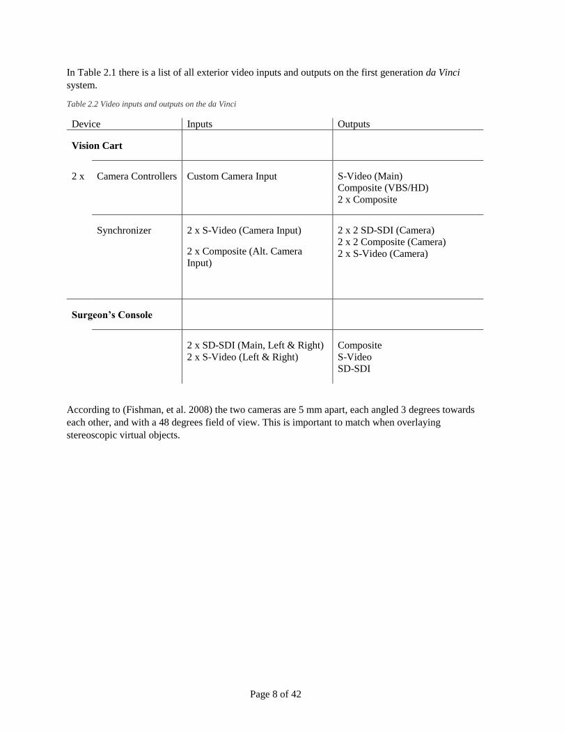
In Table 2.1 there is a list of all exterior video inputs and outputs on the first generation da Vinci
system.
Table 2.2 Video inputs and outputs on the da Vinci
Device Inputs Outputs
Vision Cart
2 x Camera Controllers Custom Camera Input S-Video (Main)
Composite (VBS/HD)
2 x Composite
Synchronizer 2 x S-Video (Camera Input)
2 x Composite (Alt. Camera
Input)
2 x 2 SD-SDI (Camera)
2 x 2 Composite (Camera)
2 x S-Video (Camera)
Surgeon’s Console
2 x SD-SDI (Main, Left & Right)
2 x S-Video (Left & Right)
Composite
S-Video
SD-SDI
According to (Fishman, et al. 2008) the two cameras are 5 mm apart, each angled 3 degrees towards
each other, and with a 48 degrees field of view. This is important to match when overlaying
stereoscopic virtual objects.

Page 9 of 42
2.2.2 da Vinci S
Figure 2.5 The second generation, da Vinci System S. Copyright ©2014 Intuitive Srigcal, Inc. (Intutive Surgical (A) 2014)
The da Vinci S is the second generation of the system and is from 2006 (see Figure 2.5). Aalborg
University Hospital currently has one of these, which is used only for training. From (Intuitive
Surgical (B) 2006) it appears that there is both SD and HD versions of the system. Aalborg University
Hospital has the HD version. Each channel of the stereo camera is connected to separate camera
controllers (Panasonic GP-US932). Each of the two camera controllers outputs two digital HD-SDI
signal, where only one from each is used (see Figure 2.6). The spare signal can be used for various
things, e.g. displaying the 3D video stream on a 3D monitor.
Figure 2.6 Back of the camera controller. (Panasonic 2014)
The HD-SDI signals enter the synchronizer at the bottom of the vision cart behind a small removable
plate (see Figure 2.7). The format detection application detects the signal between the camera
controllers and the synchronizer as 1080i59.94 with pixel format YCbCr 4:2:2. The video format has
a resolution of 1920 by 1080 pixels refreshing at 59.94 fields per second.

Page 10 of 42
Figure 2.7 Left: Removing the four screws marked with red and three more srews to the left lets you remove the cover.
Right: Behind the cover are the video inputs (blue) from the camera controllers.
The vision cart outputs the video signals through a large blue custom cable to the surgeon’s console.
Like the first generation system, the surgeon’s console outputs a one-channel video signal from the
console with icons and text back to the vision cart. This signal is connected to a touch screen, where
assisting surgeons and nurses can change which camera is displayed on the screen, calibrate the
cameras, and use the telestration-feature.
The da Vinci S has five additional video inputs, which can be utilized by the TilePro-feature. There
are two S-Video (Y/C) inputs on the vision cart and two on the surgeon’s console. Additionally there
are DVI-inputs and -outputs on the surgeon’s console.
The priority of the signals for TilePro are (Intuitive Surgical (B) 2006):
1. DVI (Surgeon’s console)
2. S-Video #1 (Vision Cart)
3. S-Video #2 (Vision Cart)
4. S-Video #3 (Surgeon’s console)
5. S-Video #4 (Surgeon’s console)
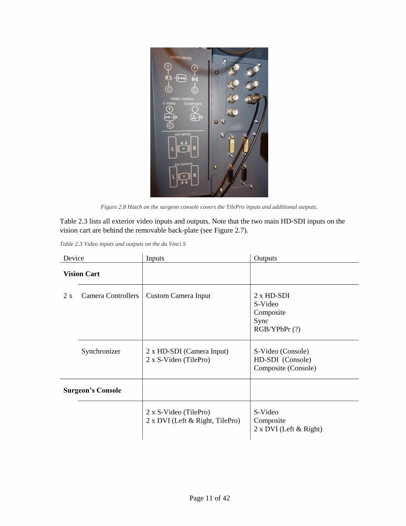
The console outputs an S-Video and a composite signal. A hatch covers the inputs and outputs on the
console (see Figure 2.8).
Page 11 of 42
Figure 2.8 Hatch on the surgeon console covers the TilePro inputs and additional outputs.
Table 2.3 lists all exterior video inputs and outputs. Note that the two main HD-SDI inputs on the
vision cart are behind the removable back-plate (see Figure 2.7).
Table 2.3 Video inputs and outputs on the da Vinci S
Device Inputs Outputs
Vision Cart
2 x Camera Controllers Custom Camera Input 2 x HD-SDI
S-Video
Composite
Sync
RGB/YPbPr (?)
Synchronizer 2 x HD-SDI (Camera Input)
2 x S-Video (TilePro)
S-Video (Console)
HD-SDI (Console)
Composite (Console)
Surgeon’s Console
2 x S-Video (TilePro)
2 x DVI (Left & Right, TilePro)
S-Video
Composite
2 x DVI (Left & Right)

Page 12 of 42
Between the vision cart and the surgeon’s console there is a blue custom-made cable that carries the
multiple video signals. Additionally there are audio inputs and outputs and a green custom made
cable to connect those between the vision cart and the surgeon’s console.
According to (Intuitive Surgical (B) 2006) the cameras on the HD version of the system have a 60
degree field of view, whereas the SD version either has a 45 degree field of view with high
magnification or 60 degree with wide-angle.
2.2.3 da Vinci Si
Figure 2.9 The third generation, da Vinci Si. Copyright ©2014 Intuitive Srigcal, Inc. (Intutive Surgical (A) 2014)
The third generation system, da Vinci Si (see Figure 2.9), was released in 2009 (Intutive Surgical (A)
2014). At Aalborg University Hospital, there are two complete da Vinci Si systems and an additional
surgeon’s console. The two systems are used for real surgeries and the additional surgeon’s console is
used either for assisting in surgeries or for training with the da Vinci Skills Simulator.
Because these systems are used for real surgeries, the operating rooms have to be kept as clean as
possible and we decided not to set up the input-test hardware. Fortunately, the product page for
specifically the da Vinci Si states that the video resolution is 1080i (Intuitive Surgical (C) 2014). The
pixel format is most likely YCbCr422 like the da Vinci S.
On this version, both channels from the stereoscopic camera are connected to the same camera
controller, which only has one HD-SDI output for each image (for left and right eye). The two HD-
SDI outputs are connect to a customized system, the CORE, at the bottom of the vision cart. This
system outputs video, audio, and robot controls through a blue optical fiber cable that is connected to
the surgeon’s console. Four fiber optics outputs are available, where the patient cart and surgeon’s
consoles each use one.

Page 13 of 42
Figure 2.10 Left: Back of the console has TilePro intputs and stereo DVI outputs. Right: VEK wtih TilePro inputs and
adjustable stereo output in different formats.
On the back of the surgeon’s console, there are additional video inputs and outputs (see Figure 2.10).
The inputs are all for the TilePro-feature and the outputs can be used to display the left and right
images, likely with icons and text, from the console. The two DVI outputs are marked with SXGA,
which suggests that they only output a resolution of 1280 by 1024 pixels.
On the CORE, there is an option to install a Vision Expansion Kit (VEK) with more inputs and
outputs. The module includes two TilePro inputs similar to those on the console. Additionally it adds
four different types of output from both the right and the left channel (see Figure 2.10). It is possible
to change what they output through the touch screen. They can output the video with icons from the
surgeon console, with icons from the touch screen, or without icons.
Table 2.4 lists all exterior video inputs and outputs.
Table 2.4 Video inputs and outputs on the da Vinci Si
Device Inputs Outputs
Vision Cart
Camera Controller Custom Camera Input 2 x HD-SDI (Main, Left & Right)
2 x Component (Left & Right)
Synchronizer 2 x HD-SDI (Camera Input) DVI (Console)
Composite (Console)
S-Video (Console)
HD-SDI (Console)
Touchscreen (RGBO)
Page 14 of 42
Optional 2 x DVI (TilePro)
2 x S-Video (TilePro)
2 x HD-SDI (TilePro)
2 x DVI (Left & Right)
2 x Composite (Left & Right)
2 x S-Video (Left & Right)
2 x HD-SDI (Left & Right)
Surgeon’s Console
2 x S-Video (TilePro)
2 x DVI (TilePro)
2 x HD-SDI (TilePro)
2 x DVI (SXGA, Left & Right)
The field of view of the cameras on the da Vinci Si system is also 60 degrees (Intuitive Surgical (D)
2014).
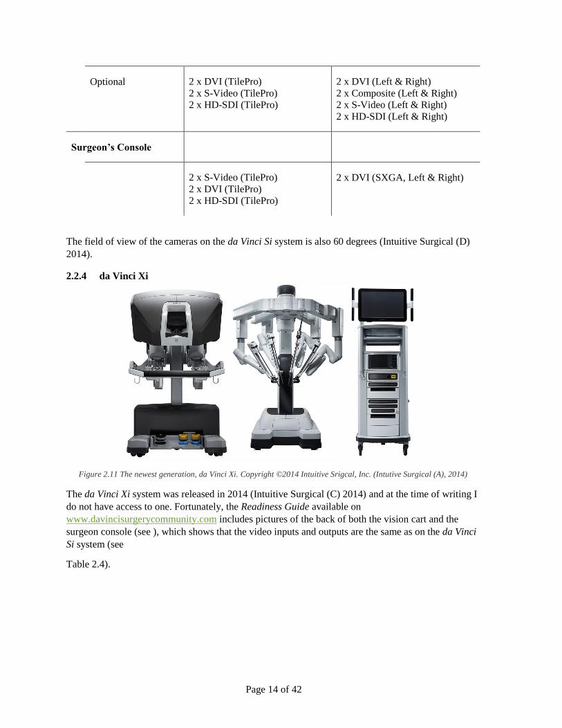
2.2.4 da Vinci Xi
Figure 2.11 The newest generation, da Vinci Xi. Copyright ©2014 Intuitive Srigcal, Inc. (Intutive Surgical (A), 2014)
The da Vinci Xi system was released in 2014 (Intuitive Surgical (C) 2014) and at the time of writing I
do not have access to one. Fortunately, the Readiness Guide available on
www.davincisurgerycommunity.com includes pictures of the back of both the vision cart and the
surgeon console (see ), which shows that the video inputs and outputs are the same as on the da Vinci
Si system (see
Table 2.4).

Page 15 of 42
Figure 2.12 Top: Back of vision cart on the da Vinci Xi system. Bottom: Back of the surgeon console on the da Vinci Xi
system. (Intuitive Surgical (E) 2014)
The release announcement for the da Vinci Xi system tells that the endoscope has been redesigned:
“A new endoscope digital architecture that creates a simpler, more compact design
with improved visual definition and clarity.
An ability to attach the endoscope to any arm, providing flexibility for visualizing the
surgical site.” (Intuitive Surgical (F) 2014)
Even though they mention improved visual definition and clarity, they still refer to the vision as 3D
HD, which indicates that it has not been upgraded to higher resolution formats like Ultra HD or 4K.
Furthermore, the inputs and outputs described in the Readiness Guide do not support higher than
1080i format (HD-SDI). Currently none of the DeckLink cards support keying on higher than an HD-
SDI signal.
A possibility is that they have implemented an improved pixel format like 10-bit RGB 4:4:4 that has a
higher color range and does not subsample. The DeckLink cards do support the 10-bit RGB pixel
format.
2.2.5 Summary
Augmenting the stream of the first generation da Vinci system can be done between the vision cart
and the surgeon console, which are connected by BNC-cables using SD-SDI. The video format is
PAL and the pixel format is YCbCr 4:2:2.
On the three newer system, the stream should be intercepted between the camera controllers and the
synchronizer/CORE, which are connected by BNC-cables using HD-SDI. On the Si and Xi systems, it
should also be possible to get the video stream from the VEK-module and input the augmented

Page 16 of 42
stream using the TilePro-feature (only DVI supports stereo input). The video format is 1080i and the
pixel format is YCbCr 4:2:2. I have only been able to confirm the pixel format on the S system.
2.3 YCBCR 4:2:2 The pixel format detected on the systems is 8-bit YCbCr 4:2:2. It is a format that utilizes chroma
subsampling to reduce the data size of a video signal or file. Where RGB stores red, green, and blue
values for each pixel, YCbCr 4:2:2 only stores luminance (brightness) for each pixel and shares Cb
and Cr between two adjacent pixels. Cb is the difference between blue and luminance, and Cr is the
difference between red and luminance (Lambrecht 2001). The DeckLink API stores YCbCr like
shown in Figure 2.13. Two pixels take up 32 bits of memory. The format is named YUV in some
places in the API, even though that is the analog version of the format. Unfortunately, this makes it
difficult to know exactly how the DeckLink cards convert between RGB and YCbCr, as the
conversion constants are different.
Figure 2.13 YCbCr 4:2:2 pixel format's memory layout. (Blackmagic Design (B) 2014)
The DeckLink API and most standard textures on a GPU also include an alpha value for each pixel in
an RGB image (see Figure 2.14). Thus, each pixel in an RGBA image takes up 32 bits of memory. An
YCbCr image then requires half the space and bandwidth of an RGBA image of the same resolution.
Figure 2.14 BGRA pixel format's memory layout. (Blackmagic Design (B) 2014)
In most cases chroma subsampling does not reduce the perceived image quality, because visual acuity
for difference in color is significantly lower than difference in luminance (Lambrecht 2001). High
color difference between pixels that share chroma can in some cases cause visible artifacts like in
Figure 2.15.
Figure 2.15 Visible artifacts caused by chroma subsampling. (Chan 2007)
2.4 HARDWARE REQUIREMENTS For the first generation, da Vinci system a DeckLink Duo (or two DeckLink SDI) is sufficient to
overlay images using the internal keyer, as the video signal is of SD resolution. The DeckLink Duo is
also able to input (capture) the stereo video from the vision cart or the one channel video from the
surgeon’s console. I assume this is also true for the non-HD version of the da Vinci S.

Page 17 of 42
The HD version of the da Vinci S and the da Vinci Si both use a 1080i video signal, which the
DeckLink Duo’s keyer does not support. However, it can still output and input a 1080i signal and is
sufficient for capturing or outputting the stereoscopic video stream. To overlay images in HD a more
advanced device is needed. The DeckLink HD Extreme cards (any generation) support internal HD
keying (see Figure 2.16).
Figure 2.16 Blackmagic Design DeckLink 4K Extreme capture, playback and keying card. (Blackmagic Design (A) 2014)
The DeckLink HD Extreme cards are: DeckLink HD Extreme, DeckLink HD Extreme 2, DeckLink
HD Extreme 3, DeckLink HD Extreme 3D and DeckLink 4K Extreme. The first generation card is
possibly not supported by the newest driver.
Both the DeckLink Duo and the DeckLink Extreme cards require a second-generation PCI-express
socket with at least x4 bandwidth.
I have investigated other hardware solutions, but nothing compared to the DeckLink cards in terms of
price and capabilities (internal keying).
Figure 2.17 RG-59 coaxial cables with BNC connectors used for the video signals.
RG-59 coaxial cables with BNC connectors (see Figure 2.17) should be used to connect to the SDI
inputs and outputs. The impedance of a RG-59 coaxial cable is 75 Ω, where the coaxial cables used
for e.g. laboratory equipment and networking often are 50 Ω RG-58 cables. To avoid reflections, the
impedance should be consistent throughout the system (75 Ω).

Page 18 of 42
Page 19 of 42
3 SYSTEM DESCRIPTION
As the main purpose of this project is to reduce initial investigation and implementation time required
for future work, the system should support multiple resolutions and formats, and a variable number of
DeckLink cards either as inputs, outputs or for keying. For instance, a DeckLink Duo is sufficient for
keying on the first-generation da Vinci system, while two DeckLink Extremes are needed for keying
on the newer generations that have higher resolution video. Even more DeckLink cards should be
supported by the system to allow for keying and capture at the same time; for instance, by using two
DeckLink Extremes for keying and a DeckLink Duo for capturing simultaneously on the same
system.
3.1 VIDEO HARDWARE To be able to implement the system effectively, without the need for a da Vinci system, we acquired
additional hardware and built the setup described below.
To simulate the output of the surgeon’s console I used a DeckLink Duo to output either two PAL or
two 1080i video signals. These signals are connected to two second-generation DeckLink Extremes
installed in another desktop computer. The DeckLink HD Extreme cards can then be used for
implementing and testing dual stream input, output and keying. Additionally, the second computer
has a Gigabyte GeForce GTX660 graphics card installed for effective rendering and format
conversions.
To display the signal generated by the DeckLink HD Extremes we acquired a Matrox MC-100 and a
consumer grade 3D TV (LG 32LB650). The MC-100 can take two HD-SDI signals and convert them
to 3D HDMI. It can output as either over/under, side-by-side or frame packed. It also has two HD-
SDI outputs that can pass-through the signals or output the 3D signal. The MC-100 is connected by
HDMI to the 3D TV, which displays the stereoscopic video.
The 3D TV uses passive polarized technology to display 3D video. It requires the users to wear light
low-cost polarized glasses. The glasses block light from every second horizontal line of pixels for one
eye, while displaying it for the other eye. The top-most line is only visible to the left eye; the second
line is only visible to the right eye, the third line to the left eye etc.
To use the system with the da Vinci systems the outputs from the camera controller should be
connected to the DeckLink HD Extremes. The output from the DeckLink cards should be connected
to the synchronizer/CORE on the vision cart. Optionally the MC-100 can be connected between the
DeckLink cards and the synchronizer to display the stereoscopic video on a 3D monitor.
3.1.1 Compatibility problems
As mentioned in Section 2.4, the DeckLink HD Extremes require at least a second-generation PCI-
express socket with x4 bandwidth. To properly work with the motherboard (Gigabyte GA-Z77X-
D3H) used in the second computer, the bandwidth has to be explicitly set in the BIOS to x4. If it is set
to the standard value AUTO, it limits the DeckLink Extreme card to x1, which makes the input and
output flash, as it cannot transfer the image data fast enough.
Additionally, I had to update the BIOS for the motherboard to support the graphics card.
The power supply unit (PSU) in the second computer was initially too weak at 450 Watts. With both
the two DeckLink Extremes and the graphics card installed the main voltage dropped below 11.5 Volt

Page 20 of 42
and caused sudden shutdowns. Switching to a spare 1000 Watts PSU, made the system stable at 12
Volt.
We bought the DeckLink Extremes used and one of them did not appear in Windows Device
Manager. The DeckLink drivers are supposed to upgrade the firmware automatically on the cards, but
the firmware was too old for the driver to register the card. Installing an older driver (version 9.5.3)
made the card appear and made the driver update the firmware. The newest driver (version 10.0.3)
then registered the card and updated it to the newest firmware. Both driver versions are on the DVD
in Appendix B.
3.2 USER INPUT DEVICES To control the virtual instruments or other objects in three dimensions we acquired some consumer
input devices. The Razer Hydra has been used in previous work with the da Vinci systems
(Galsgaard, et al. 2014) (Grande, et al. 2013) (Kibsgaard, Thomsen og Kraus 2014). It has six degrees
of freedom (position and orientation), six buttons, one analog trigger, and a joystick on each of the
two controllers. It is no longer in production, but its successor, STEM System, is being released in
October 2014, and should support the same SDK. The main improvements are wireless controllers, a
larger range, and no line of sight requirement (Sixense 2014).
The Leap Motion controller is able to track hand position and to some extent orientation. Initial
testing with the device suggested that it was too imprecise for tracking anything but a relaxed hand.
The Kinect for Windows v2 sensor was released in July 2014, just in time for the evaluation of this
system. It can track the skeleton of a user with precision positions of each joint. It is also able to track
orientations of the joints to some degree, but that requires some filtering to be usable (flickering). It
requires direct line of sight as it uses depth and infrared cameras to detect the users. For that reason, it
also has problems with occlusions. The sensor can detect three hand gestures: open hand, closed hand
and lasso (only index and middle finger stretched).
Control VR is a new controller to be released December 2014 (Control VR 2014). It can track torso,
arms, and fingers of a user. Finger position and orientation could be used to mimic how you control
the tools on the da Vinci systems.
3.3 SOFTWARE For the system to support three-dimensional virtual instruments, a graphics engine is required. Due to
prior experience and availability, I choose to implement the system in the game engine Unity. Using a
fully developed game engine like Unity makes it easy to use and build upon for future work. The
system is implemented as a Unity-package, which can be included in any project to add support for
input, output, and keying on DeckLink devices. It is implemented using version 10.0.3 of the
DeckLink SDK and version 4.5.2f1 of Unity.
The core of the package is a script called DeckLinkManager that displays all DeckLink devices
installed in the computer. By adding the script to a GameObject in the scene, the developer is able to
choose what each device should do. The script has a custom-made inspector interface that displays all
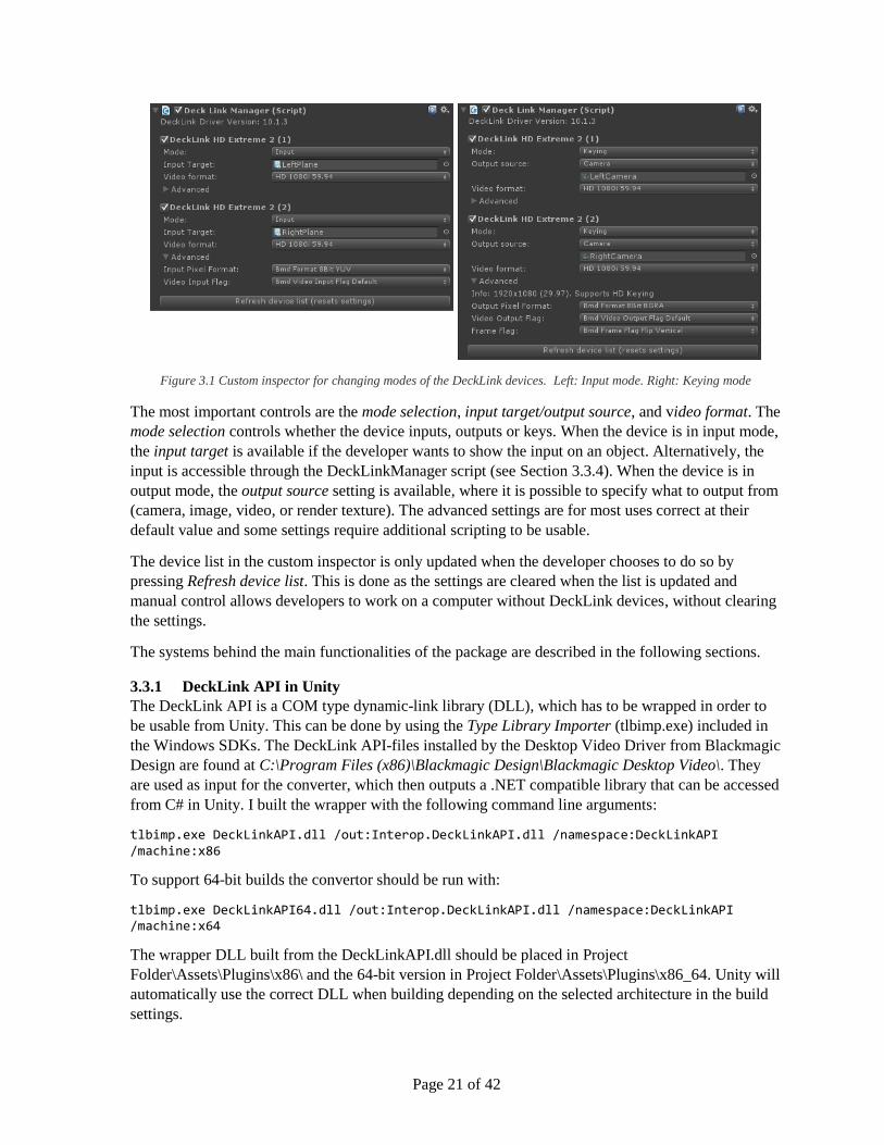
the settings for each device, as seen in Figure 3.1.
Page 21 of 42
Figure 3.1 Custom inspector for changing modes of the DeckLink devices. Left: Input mode. Right: Keying mode
The most important controls are the mode selection, input target/output source, and video format. The
mode selection controls whether the device inputs, outputs or keys. When the device is in input mode,
the input target is available if the developer wants to show the input on an object. Alternatively, the
input is accessible through the DeckLinkManager script (see Section 3.3.4). When the device is in
output mode, the output source setting is available, where it is possible to specify what to output from
(camera, image, video, or render texture). The advanced settings are for most uses correct at their
default value and some settings require additional scripting to be usable.
The device list in the custom inspector is only updated when the developer chooses to do so by
pressing Refresh device list. This is done as the settings are cleared when the list is updated and
manual control allows developers to work on a computer without DeckLink devices, without clearing
the settings.
The systems behind the main functionalities of the package are described in the following sections.
3.3.1 DeckLink API in Unity
The DeckLink API is a COM type dynamic-link library (DLL), which has to be wrapped in order to
be usable from Unity. This can be done by using the Type Library Importer (tlbimp.exe) included in
the Windows SDKs. The DeckLink API-files installed by the Desktop Video Driver from Blackmagic
Design are found at C:\Program Files (x86)\Blackmagic Design\Blackmagic Desktop Video\. They
are used as input for the converter, which then outputs a .NET compatible library that can be accessed
from C# in Unity. I built the wrapper with the following command line arguments:
tlbimp.exe DeckLinkAPI.dll /out:Interop.DeckLinkAPI.dll /namespace:DeckLinkAPI /machine:x86
To support 64-bit builds the convertor should be run with:
tlbimp.exe DeckLinkAPI64.dll /out:Interop.DeckLinkAPI.dll /namespace:DeckLinkAPI /machine:x64
The wrapper DLL built from the DeckLinkAPI.dll should be placed in Project
Folder\Assets\Plugins\x86\ and the 64-bit version in Project Folder\Assets\Plugins\x86_64. Unity will
automatically use the correct DLL when building depending on the selected architecture in the build
settings.
Page 22 of 42
All functionality of the DeckLink API can then be accessed directly in C# by its namespace:
using DeckLinkAPI;
The IDeckLinkIterator interface exposes available DeckLink devices that are not currently being used
by other applications (Blackmagic Design (B) 2014). The IDeckLink interface represents each device
and can be used to get the input, output and keyer interfaces.
3.3.2 Outputting video
The IDeckLinkOutput interface can acquire a display mode iterator that tells which display modes are
supported by the specific DeckLink device. I use this information to adjust the modes available in the
custom inspector interface.
At startup of the application, the IDeckLinkOutput interface is reacquired and used to check if the
combination of settings is supported. If it is, the output is enabled with the selected display mode and
flags. Then the interface is used to create a video frame with the chosen pixel format and frame flag.
The default pixel format is BGRA and the default frame flag is flip vertical.
One of the main reasons for implementing the system with Unity is to be able to output real-time 3D
graphics. To do this, each time a frame is rendered, it has to be transferred from GPU to CPU
memory to become available for the DeckLink device. In Unity, this can be done by the following
code (attached to a camera):
void OnPostRender () { texture.ReadPixels (new Rect (0, 0, width, height), 0, 0); // 40 ms texture.Apply (false); // 12 ms colors = texture.GetPixels32 (); } // 4 ms
However, for one 1920 by 1080 pixels (full HD) frame that takes 56 milliseconds and the data still
has to be copied into the frame created by the IDeckLinkOutput interface. To display stereoscopic
graphics, two frames have to be output each frame. By transferring two full HD frames with this
method, the application can only run at 7 frames per second (fps). That is still without copying the
data to the DeckLink frame.
Another method for transferring a frame from the GPU is to use the function glReadPixels. However,
this requires Unity to run in OpenGL-mode instead of DirectX when using Windows. The default
graphics library is OpenGL when using Unity on Mac or Linux. On Windows, Unity can be launched
in OpenGL-mode by executing it with the command line argument -force-opengl. The glReadPixels
function can then be imported directly from the opengl32 library present on the system:
[DllImport("opengl32")] public static extern void glReadPixels(int x, int y, int width, int height, int
format, int type, IntPtr buffer);
The function reads from the currently active frame buffer, which is always where the camera rendered
to, when the function OnPostRender is called. It outputs directly to a memory address, which is what
the DeckLink frame gives as a target for the image data. The function is able to transfer the data from
the GPU to the DeckLink frame in 10 ms. Using this method the application with two full HD frames
can run at 36 fps.

Page 23 of 42
Importing a native C function like glReadPixels requires a Unity Pro license. However, it is possible
to wrap the function in a C# library that is usable with the free version of Unity. Such a wrapper can
be created with MonoDevelop (bundled with Unity) by creating a new C# Library project that
implements the glReadPixels function:
using System; using System.Runtime.InteropServices; namespace DeckLinkOpenGL { public class OpenGL { [DllImport("opengl32")] public static extern void glReadPixels(int x, ... ); } }
It compiles as a DLL and is used from Unity the same way the DeckLink API wrapper is used (see
Section 3.3.1).
The developer can add a camera to the output source of the custom inspector interface and it will
automatically add a script to the camera, which calls glReadPixels each time it has rendered. The
target memory address to a DeckLink frame is set from the DeckLinkManager script on start.
Additionally, I have implemented a class that is able to output an image selected by an open file
dialog. In its current implementation, it uses Unity’s resource-loader class www, which uploads
images directly to the GPU. The image data is then copied back to the CPU and into a DeckLink
frame. Optimally the image data should be accessible directly in the CPU memory. The output source
also has a movie setting, which has not been implemented yet.
3.3.3 Keying
The keyer interface can be acquired from each DeckLink device. When enabled, it is possible to
choose between internal or external keying. External keying will output the image (fill) on one SDI
and an alpha mask (key) on another. This can be used in a video mixer to overlay the image on
another video stream. The internal keyer overlays the image directly into the input video stream of the
DeckLink device.
The alpha channel of the output frame is used as the opacity of the overlay image. The keyer interface
also allows changing the overall opacity of the overlay, either instantly or over a number of frames
(ramp up/down).
3.3.4 Inputting video
Before enabling input, a callback target has to be set. Each time a new frame arrives the
VideoInputFrameArrived method of the callback target is called. I implemented this in the
DeckLinkDevice class, which I also use to store settings and capabilities of each card.
When a new frame arrives, the memory address is stored and can be read directly in CPU memory if
the developer wants to process it. At the end of each Unity frame, the image data is also uploaded to
the GPU as a texture to display the input. Similar to outputting, this is done using OpenGL functions
implemented in the same wrapper DLL. glBindTexture is used to set the target texture on the GPU
and glTexSubImage2D is used to transfer the data to the GPU.

Page 24 of 42
As the pixel format is YCbCR (see Section 2.3) it has to be converted to RGB for most purposes. The
DeckLink SDK includes an example of a shader that does this conversion (Blackmagic Design (B)
2014). I have implemented a version of the shader in Unity that can be used on a material if the
developer only wants to use it for displaying the input. It is also possible to convert the input to RGB
without directly displaying it using Graphics.Blit. However, this last functionality requires a Unity
Pro license.
The callback target also has to implement a method for detecting input format changes. I use this
method for stopping the input stream, resizing textures and DeckLink frames, and restarting the
stream with the detected formats. It also prints the detected formats in the console.
3.3.5 Input devices
I have implemented a class, which is able to receive input from the different devices. The developer is
able to easily change the input device by the custom inspector interface or by script. The class
translates the information from the different devices into a more homogeneous format, so the
developer can get position, orientation, and button states in one place independent of which device is
in use.
The devices that I have implemented are the Kinect for Windows v2, Razer Hydra (and STEM), and
basic mouse control, where the scroll wheel adjust the depth. I plan to implement more devices as I
acquire them. The position read from the Kinect sensor, is the vector between the hand and upper-
torso joints rotated to the orientation of the main camera in the scene and offset by the position of the
camera. This means that the position in front of the camera is relative to where the hand is in front of
the torso. The user’s position relative to the sensor is then less important.
The trigger on the Hydra, left button on the mouse, and the closed hand gesture on the Kinect controls
the same value called Trigger [0…1], which is the primary button input. The 1 and 2 button, the right
mouse button and the lasso hand gesture is used as secondary button input.
3.3.6 da Vinci prefabs
In Unity, a prefab (short for prefabricated) is a stored object that includes components (scripts) and
properties (script values) which can be used to easily instantiate a complex object. I use it to include a
virtual instrument that can be dragged into any scene. To control the instrument with the Razer Hydra
or the Kinect, their respective prefabs have to be dragged into the scene as well.
To give an example of how to use the input device class, I have implemented a script that utilizes the
information to control an instrument similar to the standard pincer instruments on the da Vinci
systems. The Trigger value is used to open and close the pincers. The secondary button input was
used to create smoke similar to the smoke when cauterizing. However, the evaluation proved it to be
distracting and confusing (see Chapter 0). Instead, it is used to clutch the virtual instruments, i.e.
moving the controllers without moving the instruments. A third button is used to clutch the entry
point of the tools.
Page 25 of 42
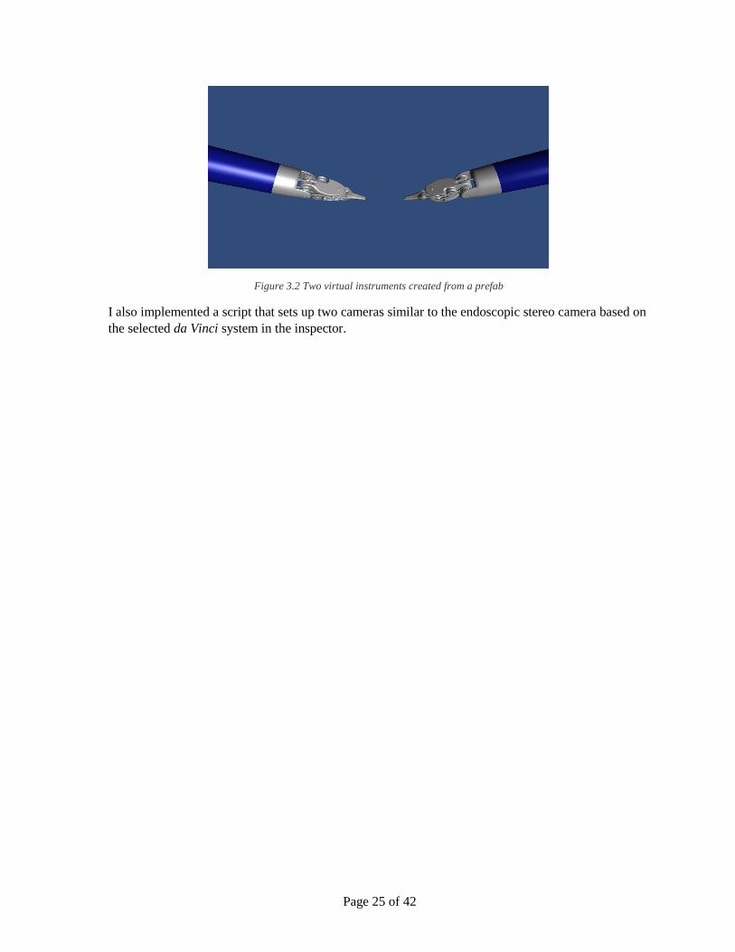
Figure 3.2 Two virtual instruments created from a prefab
I also implemented a script that sets up two cameras similar to the endoscopic stereo camera based on
the selected da Vinci system in the inspector.

Page 26 of 42

Page 27 of 42
4 SYSTEM TEST
4.1 OPTIMIZATION The optimal formats for transferring textures to and from the GPU are BGRA and
UNSIGNED_INT8888_REV as it requires no conversion or shuffling. This might be different on
other setups and operating systems.
To improve the performance of outputting from the GPU, I wrote a shader that converts BGRA to
YCbCr 4:2:2, which is the format used by the da Vinci systems. It reduces each frame to half the size,
and allows for 78% higher frame rate, when outputting two full HD frames. It cannot be used for
keying, which requires an alpha channel. Using this shader (Graphics.Blit) requires Unity Pro.
4.2 PERFORMANCE TESTS I have tested the performance of the system’s functionalities on the two setups I have available with
three different scenes. The first scene is just a cube and two cameras (56 triangles). The triangle count
is doubled because of the two cameras. The second scene has two high quality virtual instruments
resembling the tools on the da Vinci system (103.000 triangles). The third scene has a very high
polygon count to stress the GPU (1.100.000 triangles). All scenes are tested with output, keying, and
input of 1080i frames. On Setup 1, outputting with BGRA format is tested instead of keying, as the
DeckLink Duo cannot key in HD. Keying and outputting in BGRA format has the same performance.
Table 4.1 Setup 1: Intel Core i5 3.2 GHz (2 cores, 4 threads), Intel HD4000 GPU (intergrated), 8 GB RAM, DeckLink Duo
Triangles CPU Load (%) Frame time (ms) FPS Index 59.94
Output (YCbCr) 56 19 11 91 1.52
2 x Output 56 18 20.2 49 0.82
2 x Output 103 k 21 56.2 18 0.30
2 x Output 1.1 mil 27 261.6 3.9 0.07
Output (BGRA) 56 23 15.4 65 1.08
2 x Output 56 25 28.1 35 0.58
2 x Output 103 k 24 63.2 16 0.27
2 x Output 1.1 mil 27 270.3 3.7 0.06
Input 876 17 8.6 116 1.94
2 x Input 876 17 14.0 72 1.20
2 x Input 103 k 27 42.5 23 0.38
2 x Input 1.1 mil 27 211.0 4.8 0.08

Page 28 of 42
Table 4.2 Setup 2: Intel Core i3-3240 3.4 GHz CPU (2 cores, 4 threads), Gigabyte Geforce 660 GTX GPU, 8 GB RAM 1600
MHz, 2 x DeckLink Extreme (2nd gen.)
Triangles CPU Load (%) Frame time (ms) FPS Index 59.94
Output (YCbCr) 56 28 8.0 125 2.09
2 x Output 56 29 14.9 67 1.12
2 x Output 103 k 29 15.3 66 1.10
2 x Output 1.1 mil 28 16.3 61 1.02
Keying (BGRA) 56 28 13.8 73 1.22
2 x Keying 56 29 26.6 37 0.62
2 x Keying 103 k 29 27.0 37 0.62
2 x Keying 1.1 mil 29 28.1 36 0.60
Input 876 27 3.1 331 5.52
2 x Input 876 27 4.7 213 3.55
2 x Input 103 k 27 5.1 196 3.27
2 x Input 1.1 mil 27 5.1 196 3.27
All these measurements require data to be transferred either from or to the GPU. Outputting image
frames directly from CPU memory can be done in 2.1 ms (479 FPS) for one output and 3.9 ms (255
FPS) for two outputs. This shows that the bottleneck (at least on the second system) is the data
transfers between the CPU and GPU memory.
4.3 LATENCY TEST As the overlaying does not create an immediate visible delay, I developed a simple test that should be
able to measure if there are one or more frames latency. I modified the SignalGenerator example from
the DeckLink SDK (Blackmagic Design (B) 2014) to output on two DeckLink devices. It outputs a
white square in the left side of the image, which expands 200 pixels to the right each frame.
Connecting both outputs directly to the MC-100 and showing the output as an over-under image,
shows that the two white squares from each output aligns vertically. Connecting one of the signals to
another DeckLink device that overlays graphics is sometimes one frame faster than the other direct
signal (see Figure 4.1).

Page 29 of 42
Figure 4.1 3D TV showing over-under image of the latency test. On top is the keyed signal and on bottom the direct signal.
The keyed signal is one frame ahead.
It is also possible for the frames to align or the keyed frame to be one frame delayed. I assume this is
because of the synchronizer in the MC-100 (Matrox 2014) and the timing of when the keyer is
activated. One frame difference between the two signals is the maximum observed with this method.
Although this method is not precise, the observations suggest that the keying at most delays the signal
one frame.

Page 30 of 42

Page 31 of 42
5 USER EVALUATION
To test if the system might be useful and to get directions for future work, I conducted an end-user
evaluation at Aalborg University Hospital. I used the system to overlay the virtual instruments
described in Section 3.3.6 to test the different functionalities of the system. Notes from the evaluation
(in Danish) can be found on the DVD in Appendix B.
Jane Petersson, Surgery Assistant at Aalborg University Hospital, helped me evaluate the system. She
works with the da Vinci systems daily by assisting in surgeries and by training students. She is
currently the only one in the country certified to teach nurses to become Registered Nurse First
Assistant in Robotic Surgery. The evaluation was also supposed to include a surgeon, but he had an
emergency surgery and had to cancel.
I set up my system with the da Vinci Si system that is normally used during training sessions. The
HD-SDI signals from each camera controller were connected to the DeckLink HD Extreme 2s, where
graphics from Unity was overlaid. The output of the Extremes were connected to the MC-100, where
the HD-SDIs was set to pass-through and used as input on the bottom of the vision cart (see Figure
2.7). Additionally, a 3D TV was connected by HDMI to the MC-100 to also show the stereoscopic
video to the subject (Jane) and the test conductor (me).
Before the test, Alborg University Hospital had borrowed the 3D TV and MC-100 for a short period
and they decided to buy an identical set for their training system (which I used for the test). Normally
it is connected to the spare HD-SDI outputs on the camera controllers (see Figure 2.6).
The test was conducted as a semi-structured interview to enable discussions and create ideas for
future work. I started by shortly introducing how the system works.
Jane believes that the Razer Hydra is great for when experienced surgeons demonstrate something to
a trainee. It is important to be able to show all 7-degrees of freedom so they can show the exact
motion. She believes that experienced surgeons easily can use the Razer Hydra without much
practice, which is also what I have experienced in previous work (Grande, et al. 2013) (Kibsgaard,
Thomsen og Kraus 2014).
It is not as practical for the assisting surgeon or nurse, as they often assist with extra tools and are not
always in the same place, i.e. not able to reach the controllers. In a clinical scenario, their working
area also has to be sterile, which might be difficult with the Razer Hydra. For them, it is often
sufficient to be able to point, which currently can be difficult. Jane noted that the rotation of the
virtual tools was incorrect after a while, which was corrected during the test by resetting the scene. I
have since fixed the problem.
Using the Kinect as input device allows for more freedom in user position and sterile interaction as no
contact is required. Jane believes that this makes the device usable for assisting surgeons and nurses;
possibly also in a clinical setting. However, the advanced models of the virtual instruments are not
necessary for this interaction method. An arrow or a sphere would be sufficient and is often better as
it blocks less of the vision. The missing degrees of freedom are a limitation during training compared
to the Razer Hydra.
We discussed how drawing with the Kinect would be useful. The open hand gesture should show a
marker or arrow and the closed hand gesture should draw at the position of the marker. The lasso

Page 32 of 42
gesture could be used to clear the drawing. There should also be a way of disabling and enabling
drawing with the Kinec, e.g. by doing the lasso gesture while holding the hand above your head.
Interaction with the Kinect is also possible while being partly occluded by the robot arms, which is
often the case when assisting.
The last interaction method is using a regular mouse. It poses the same problems as the Razer Hydra
for the assisting surgeon or nurse. Like the Kinect it lacks rotation of the virtual tools, which might be
needed during training. Without rotation, the advanced models are not necessary and an arrow or
sphere would be better.
During all three interaction methods we noted that the perceived depth of the instruments was wrong.
After the test, I have corrected the size and depth of the tools in relation to video captured from the da
Vinci system at the evaluation.
Jane believes that the smoke used to simulate cauterization can cause confusion and distract the
trainee. It has very little functional purpose and the button should instead be used for clutching the
virtual tools.
Like suggested by (Galsgaard, et al. 2014), transparent overlay graphics should be evaluated.
According to Jane, transparency is a major improvement. The virtual instruments should preferably
never occlude any part of the display completely, e.g. it must not hide a hemorrhage. We adjusted the
opacity of the graphics to a level where it was still usable to display tasks to the trainee, while the
background still was visible. Based on our perception, the lowest usable opacity is 30% and 45%
opacity is preferable (see Figure 5.1).
Figure 5.1 Virtual tool overlaid the stereoscopic video with 45% opacity.
According to Jane, the color of the instruments should be green, to avoid confusion when referring to
the instruments. Green is the best color as it is rarely present in the human body. The most present
colors are red (muscles, most organs, blood, arteries); nuances of black and white (tendons, pellicle);
yellow (fat); nuances of blue and purple (veins).

Page 33 of 42
I had implemented an occlusion plane, which makes the virtual instruments look like they penetrate
the background. Jane liked that it gives extra help to see the depth. However, its usefulness is limited,
as it currently has to be adjusted manually.
Overall, Jane believes the system with a few adjustments will be useful for training. Specifically the
depth has to be corrected and a clutch has to be implemented. The ability for the assisting surgeon or
nurse to point without touching a controller can also be useful in a clinical setting.

Page 34 of 42

Page 35 of 42
6 CONCLUSION
As an initial step to improve communication during training sessions with the da Vinci systems, I
have examined and described the video hardware of the systems. I covered this in detail for it to be as
useful as possible for any kind of future work involving the video hardware (see Chapter 0).
I have developed a system which is able to input, output, and overlay graphics onto the video signals
of all current models of the da Vinci systems. It is implemented in the free version of the Unity game
engine to add support for overlaying three-dimensional objects onto the stereoscopic video stream.
The system utilizes the DeckLink PCI-express cards from Blackmagic Design. To augment the video
stream of the first generation da Vinci system, it is sufficient with a DeckLink Duo or two DeckLink
SDI, while the newer generation systems require two DeckLink HD Extreme cards. To output or
input video from any of the systems a DeckLink Duo is sufficient (see Chapter 0).
I developed the system to be used for future work as there are many possibilities, and testing if they
improve training conditions can take a long time due to the sparse amount of subjects available. The
system includes custom interfaces for Unity, which allows developers to use the functionalities of the
system without having to program or learn about the DeckLink API. The interface detects any
installed DeckLink devices and defaults to settings matching the da Vinci systems. For each device, it
is possible to set it to input, output, or key and select target (e.g. a plane) or source (e.g. a camera) for
each mode (see Section 3.3).
Furthermore, I implemented several user input devices into one class, which transforms the data from
each device into a more homogenous format. As an example, I used the class to control a virtual
instrument resembling those of the da Vinci systems. With the class, it is possible to change input
device and implement more devices without changing the code of the virtual instrument (see Chapter
0).
The system is able overlay virtual instruments on the stereoscopic video stream at 37 frames per
second on each channel (left and right eye), without delaying the video signal noticeably (see Chapter
0). I have not been able to determine the exact latency that the overlaying introduces.
I evaluated the system with the help of an end-user, who helps trainees in the previously mentioned
training scenarios (see Chapter 0). Overall, the system shows promise and with a few adjustments, it
can improve training conditions.

Page 36 of 42
Page 37 of 42
7 FUTURE WORK
As the developed system is meant for future work, ideas about what to test with the system have
already been covered in Chapter 0. It is different approached on how to visually guide a trainee sitting
at the surgeon console. As the trainee’s vision is limited to that of the camera and the robot disables if
the trainee leans back, it is currently difficult to visually communicate with the trainee.
As previously mentioned, a possible solution is to show video or image guides to the trainee directly
in the surgeon console. Another solution to test is simply displaying a (3D) webcam stream of the
trainer to the trainee. The system was developed in Unity to support testing of overlaying 3D graphics
like for instance virtual instruments and drawing in 3D. It also makes it easy for future developers
familiar with Unity to develop an application that overlays the graphics from Unity on to the
stereoscopic video stream.
If multiple of the proposed solutions are usable, it would also be interesting to develop a graphical
user interface for the trainer to enable and control the different functionalities of the system.
To test if displaying videos is useful, the DeckLink Duo can be used for recording the stereoscopic
video from the da Vinci systems. On the da Vinci S system, it can be recorded from the spare outputs
on the camera controllers. The frames can be saved directly from Unity (not implemented) or be
captured using multi-channel recording software. I recorded dual stream video with a trial version of
vMix.
To increase the frame rate of the system, when overlaying graphics, is to use an NVIDIA Quadro or
AMD FirePro graphics card. They are workstation graphics cards that support fast data transfers from
the GPU to the CPU, without stalling the rendering.
Future work should also include implementing and evaluating new user input devices like the STEM
System and ControlVR.

Page 38 of 42

Page 39 of 42
8 BIBLIOGRAPHY
Ali, Mohammed R., Jamie P. Loggins, and William D. Fuller. 2008. "3-D Telestration: A Teaching
Tool for Robotic Surgery." JOURNAL OF LAPAROENDOSCOPIC & ADVANCED
SURGICAL TECHNIQUES, 107-112.
Blackmagic Design (A). 2014. DeckLink Tech Specs. Blackmagic Design. Accessed July 2014.
http://www.blackmagicdesign.com/dk/products/decklink/techspecs/W-DLK-01.
Blackmagic Design (B). 2014. "Blackmagic DeckLink SDK." no. 10.0.4. Blackmagic Design.
Chan, Glenn. 2007. "Color Bars Vegas-DV." Wikimedia Commons. Accessed 2014.
https://commons.wikimedia.org/wiki/File:Color-bars-vegas-dv.gif.
Control VR. 2014. Control VR. Accessed August 2014. http://controlvr.com/.
Fishman, Jonathan M., Stephen R. Ellis, Christoper J. Hasser, and John D. Stern. 2008. "Effect of
reduced stereoscopic camera separation on ring placement with a surgical telerobot." Surgical
Endoscopy.
Galsgaard, Bo, Martin Møller Jensen, Florin-Octavian Matu, Mikkel Thøgersen, and Martin Kraus.
2014. "Stereoscopic Augmented Reality System for Supervised Training on Minimal
Invasive Surgery Robots." Proceedings of Virtual Reality International Conference.
Grande, Kasper, Rasmus Steen Jensen, Martin Kraus, and Martin Kibsgaard. 2013. "Low-Cost
Simulation of Robotic Surgery." Laval, France: Association for Computing Machinery.
Intuitive Surgical (B). 2006. "da Vinci S System Overview Script." no. A. Intuitive Surgical.
Intuitive Surgical (C). 2014. da Vinci Si. Intuitive Surgical. Accessed June 2014.
http://www.intuitivesurgical.com/products/davinci_surgical_system/davinci_surgical_system
_si/surgeon-control.html.
Intuitive Surgical (D). 2014. "da Vinci Si In-Service Guide: OR Staff." no. J. Intuitive Surgical.
Intuitive Surgical (E). 2014. "da Vinci Xi Surgical System Readiness Guide." no. A. Intuitive
Surgical.
Intuitive Surgical (F). 2014. Press Release - da Vinci Xi. Intuitive Surgical. April. Accessed July
2014. http://investor.intuitivesurgical.com/phoenix.zhtml?c=122359&p=irol-
newsArticle&ID=1914477.
Intutive Surgical (A). 2014. Image Gallery. Intutive Surgical. Accessed July 2014.
http://www.intuitivesurgical.com/company/media/images/.
Kibsgaard, Martin, Kasper Kronborg Thomsen, and Martin Kraus. 2014. "Simulation of Surgical
Cutting in Deformable Bodies using a Game Engine." Lisboa, Portugal: INSTICC.
Lambrecht, Christian J.v.d.B. 2001. Vision Models and Applications to Image and Video Processing.
Springer.
Lamprecht, B., W.C. Nowlin, and J.D. Stern. 2011. Stereo telestration for robotic surgery. US Patent
Patent 7,907,166.

Page 40 of 42
Matrox. 2014. Matrox MC-100 Technical Specifications. Accessed August 2014.
http://www.matrox.com/video/en/products/mc100/specs/.
Panasonic. 2014. "GP-US932CUS Tech Specs."
Sixense. 2014. STEM System. Accessed August 2014. http://sixense.com/wireless.
Wikipedia. 2014. Serial Digital Interface. Accessed August 2014.
https://en.wikipedia.org/wiki/Serial_digital_interface#Standards.

Page 41 of 42
APPENDIX A. DECKLINK API IN VISUAL STUDIO
1. Add Filter (folder) DeckLink API (optional)
2. Add Existing File…
a. DeckLinkAPI.idl 3. Right click on DeckLinkAPI.idl, Compile
4. Add Existing File…
a. DeckLinkAPI_h.h b. DeckLinkAPI_i.c
5. Right click on DeckLinkAPI_i.c, Properties, C/C++, Precompiled Headers
a. Change to “Not Using Precompiled Header” 6. The API can now be included:
a. #include “DeckLinkAPI_h.h”

Page 42 of 42
APPENDIX B. DVD
1. Source
a. C++
b. Unity
c. Wrappers
2. Builds
a. C++
b. Different Unity builds
3. DeckLink Drivers
a. 9.5.3
b. 10.0.3 / 10.0.4
4. AV-production
5. Electronic Sources
6. Photos / Video
7. Unity Package
8. Report.pdf