Embed Size (px)
Citation preview

RSCC Wire & Cable LLC © 2017 • 20 Bradley Park Road • East Granby, CT 06026 USA • 800-327-7625 Tel: 860-653-8300 • Fax: 860-653-8321 • r-scc.com
A Marmon Wire & CableBerkshire Hathaway Company
VITALink Taped Splice Pigtail Crimp1 Hour Fire-Rated Splice VITALink MC Cables, UL FHIT 120
Installation Instructions
Description
The VITALink® Taped Splice Kit contains components and instructions for assembling a 1 hour fire-rated splice on VITALink® MC Cable.
Read instructions completely before starting.
For technical support, call RSCC Wire & Cable LLC at 800-327-7625.
Tools Required
• Utility knife • Pipe cutter
• Cable cutter • Crimping tool (comply with UL listing)
• Channel Locks • Needle Nose Pliers
Materials Provided (RSCC part number VX99000-001)• 2 Rolls of item A below: Self-sealing silicone rubber electrical tape
• 1 Roll of item B below: Fiberglass tape
Additional Materials Required • Adalet stainless steel NEMA 4X enclosure with silicone gasket (Series TRN4X-S)
• Stainless steel breather/drain
• American Connector stainless steel MC connector – Type WT-WSE (See Figure 1)
• Thomas&Betts tin plated copper compression wire joint (See Figure 1)
WARNING: IMPORTANT: Installation GuidelinesThe VITALink® MC Splice Kit system must be installed by qualified personnel familiar with generally accepted construction techniques and safe electrical practices.
• Take all appropriate precautions when installing splices, including following OSHA and other applicable regulations.
• To ensure this kit is installed correctly, read and follow all the safety warnings and instructions contained in this document.
• Only stainless steel enclosures and stainless steel MC connectors may be used.
• The installation must comply with all national and local electrical codes and all the requirements of the UL Electrical Circuit Integrity System listing (UL Category FHIT, System #120) requirements, and carefully follow the installation instructions.
• Ensure the cable is in good condition prior to commencing splice installation.
• Do not pull cables around corners that have sharp edges, such as corners in cable trays, or other obstructions.
• Support the cable in the manner and at the intervals described in the Electrical Circuit Integrity System listing.
A B
Materials not supplied
Stainless steel connector
Picture does not represent all tape splice configurations.
Figure 1
Compression Wire Joint
Ground wire Breather/drain
RSCC Wire & Cable LLC © 2017 • 20 Bradley Park Road • East Granby, CT 06026 USA • 800-327-7625 Tel: 860-653-8300 • Fax: 860-653-8321 • r-scc.com
VITALink® MC 1 Hour Taped Splice Kit Installation Instructions – Pigtail
2
Patent No.7,339,115 B2
MC Connector Installation
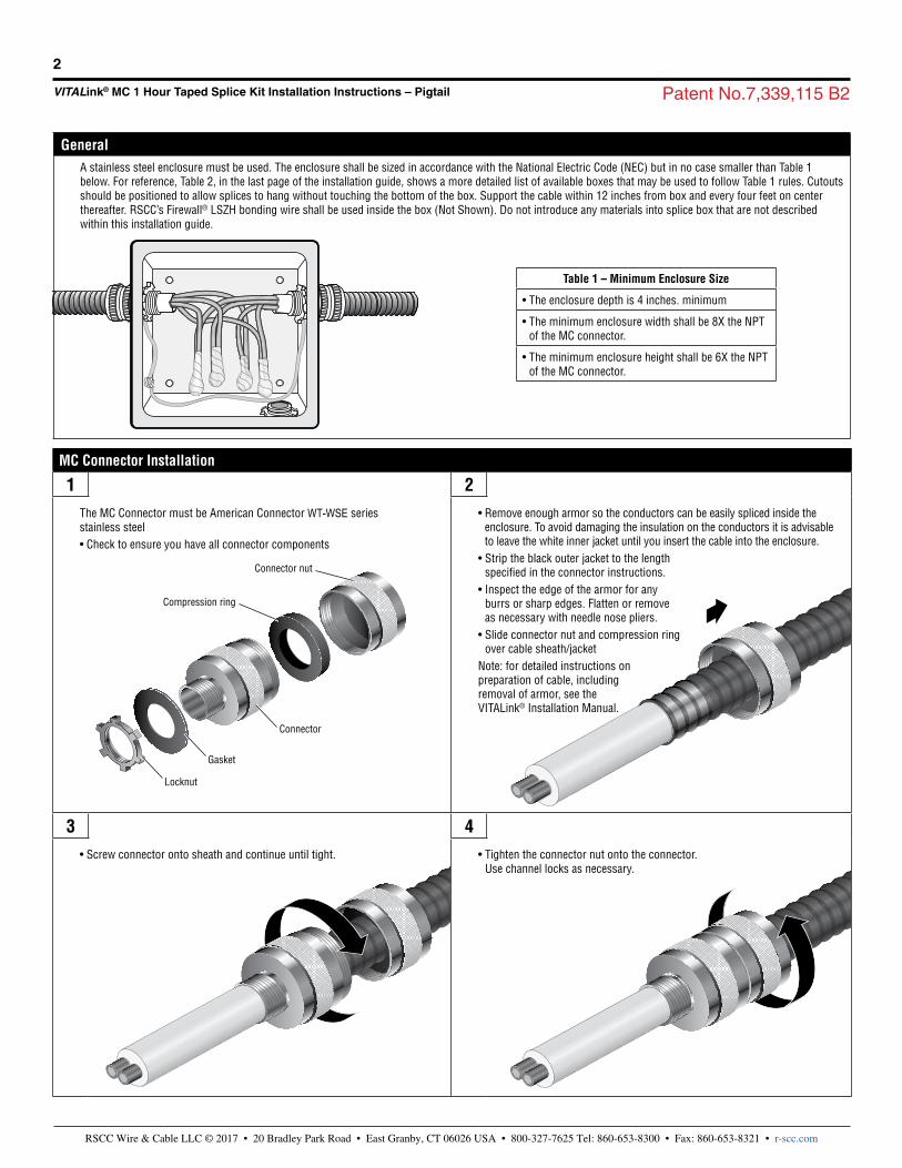
1 2The MC Connector must be American Connector WT-WSE series stainless steel• Check to ensure you have all connector components
• Remove enough armor so the conductors can be easily spliced inside the enclosure. To avoid damaging the insulation on the conductors it is advisableto leave the white inner jacket until you insert the cable into the enclosure.
• Strip the black outer jacket to the lengthspecified in the connector instructions.
• Inspect the edge of the armor for anyburrs or sharp edges. Flatten or removeas necessary with needle nose pliers.
• Slide connector nut and compression ringover cable sheath/jacket
Note: for detailed instructions on preparation of cable, including removal of armor, see the VITALink® Installation Manual.
3 4• Screw connector onto sheath and continue until tight. • Tighten the connector nut onto the connector.
Use channel locks as necessary.
Connector nut
Compression ring
Connector
Gasket
Locknut
Table 1 – Minimum Enclosure Size
• The enclosure depth is 4 inches. minimum
• The minimum enclosure width shall be 8X the NPT of the MC connector.
• The minimum enclosure height shall be 6X the NPTof the MC connector.
GeneralA stainless steel enclosure must be used. The enclosure shall be sized in accordance with the National Electric Code (NEC) but in no case smaller than Table 1 below. For reference, Table 2, in the last page of the installation guide, shows a more detailed list of available boxes that may be used to follow Table 1 rules. Cutouts should be positioned to allow splices to hang without touching the bottom of the box. Support the cable within 12 inches from box and every four feet on center thereafter. RSCC’s Firewall® LSZH bonding wire shall be used inside the box (Not Shown). Do not introduce any materials into splice box that are not described within this installation guide.

RSCC Wire & Cable LLC © 2017 • 20 Bradley Park Road • East Granby, CT 06026 USA • 800-327-7625 Tel: 860-653-8300 • Fax: 860-653-8321 • r-scc.com
VITALink® MC 1 Hour Taped Splice Kit Installation Instructions – Pigtail
3
Patent No.7,339,115 B2
Straight Through Tape Splice Installation – Read Section completely before beginning installation
1 Secure Cable and Grounds 2 Remove Inner Jacket• Prepare box cutouts and file sharp edges as needed. Clean up any metal
shavings or oil. Some boxes come pre-cut.
• Install stainless steel breather drain on bottom of box.
• Ensure rubber gasket is on connector and insert cables into enclosure taking care not to nick or cut the cable core.
• Attach and secure the MC connector to the steel box using the locknut.
• Attach the earth tag and secure second locknut to the MC connector.
• Attach bare ground or Firewall LSZH green ground to the earth tag and ground stud to bond the connector and box to ground.
• Taking care not to nick or cut the black insulation, carefully remove the white inner belting material leaving minimum of ½ inch where the cable exits the threaded part of the MC connector. One method to accomplish this is to cut through the end of the inner jacket ½ inch inward and use your hands to peel the jacket back. This is preferred over scoring the jacket lengthwise down the cable because it eliminates the risk of cutting the insulation accidentally. Damage to the insulation will require a new piece of cable.
3 Splice Layout and Crimp 4 Silicone Tape• Each crimp shall be cut so that they are staggered in the box when complete
(see picture in step 7).
• It is recommended to train the conductors where the crimp will be located before cutting. This will help with the splice layout. Respect bend radius limits. See Step 7 for layout.
• Cut the ends of the cable square and carefully remove the black insulation to expose the amount of conductor specified by the manufacturer of the copper compression wire joint.
• Connect the conductors together using the appropriate copper compression wire joint and crimping tool. Verify crimp is not loose.
• The first tape to apply is the gray colored supplied self-fusing silicone rubber. Several silicone tape wraps shall be applied with tension, and one final layer shall be applied without tension. Instructions are provided below. Take care to keep tape clean. Dirty tape shall be discarded. It is critical that the silicone tape stays clean.
• Start the tape 1.5 inches back from the end of the insulation and tape over the conductor insulation. Pull tape with moderate tension (50% to 100% elongation) and begin to wrap helically towards crimp. Stretching the tape is required to cure the material.
• 50% Overlap is required. Each wrap of tape shall overlap onto itself half way. Continue over the bare conductor and the crimped connection. Be sure to cover the tip of the crimp by folding the tape over the end. This is one pass. The next pass would follow the same process in reverse. There is not a need to cut the silicone tape after each pass.
• Continue this process. The number of required passes across the crimp, as described in the previous steps, to achieve the fire rating is shown in Table 2. One pass is defined as one pass across the crimp. For example starting 1.5inches from the left side of the crimp and continuing over the crimp at 50% overlap is one pass. Returning to the starting position would be the second pass, so on and so forth.

RSCC Wire & Cable LLC © 2017 • 20 Bradley Park Road • East Granby, CT 06026 USA • 800-327-7625 Tel: 860-653-8300 • Fax: 860-653-8321 • r-scc.com
VITALink® MC 1 Hour Taped Splice Kit Installation Instructions – Pigtail
4
Patent No.7,339,115 B2
Straight Through Tape Splice Installation Continued
5 Final Silicone Layer 6 Glass Protective Tape• After silicone tape has been wrapped according to Table 2, apply a final layer
of the self-fusing silicone rubber tape with zero stretch or tension. Press down to avoid the tape ends from lifting before fusing takes place.
• The Second tape to apply is the white fiberglass tape.
• Cut the glass tape so it can be applied over the end of the crimp. The tape should be cut at a length that allows it to extend from one side of the silicone taped conductor, over the tip of the crimp, and back over to the other side of the silicone taped conductor. Length will vary by cable size.
• Cut an identical piece to cover the end of the cable again, but apply this one rotated 90 degrees. The result should look like an “X” pattern of tape covering the end of the crimp. This will help ensure the tip of the crimp is covered properly.
• Next, start taping ½ inch past the end of the first layer of the silicone tape and apply one layer over the silicone tape. Each wrap of tape should cover over the previous wrap half way. Cover all surfaces of the silicone tape.
• Be careful not to cut silicone insulation or silicone tape when cutting the glass tape
• Additional layers are not required after silicone tape is covered.
• Use hand and apply pressure around crimp to ensure tape is adhering well.
7 Train Cables 8 Clean Up, Final Inspection, Close Box• It is important to train the cables neatly away from each other in the
enclosure as shown. Avoid contacting the sides of the enclosure. Maintain at least a ½ inch spacing between the splices and the inside of the enclosure sides, top or bottom.
• Remove any loose debris from inside the box.
• Inspect box cover gasket for any damage and wipe clean if it is dirty.
• Secure the box cover and gasket to the box using the clips and tighten screws (not shown).

VITALink® MC 1 Hour Taped Splice Kit Installation Instructions – PigtailPatent No.7,339,115 B2
RSCC Wire & Cable LLC © 2017 • 20 Bradley Park Road • East Granby, CT 06026 USA • 800-327-7625 Tel: 860-653-8300 • Fax: 860-653-8321 • r-scc.com
5
Table 2 – Tape Passes, Box Sizes, and Wire Joint
Conductor Size
Conductor cmil
Conductor Number
Insulation Thickness
(mils)
Number of Tape Passes Under
Tension
Connector Hub OD (In)
Box Size WxHxD (In)
Thomas&Betts Wire Joint
Cat. No./Color
14 AWG 4110
2 60 6 0.75 6x6x4 NA
3 60 6 0.75 6x6x4 NA
4 60 6 0.75 6x6x4 NA
5 60 6 1 8x6x4 NA
6 60 6 1 8x6x4 NA
7 60 6 1 8x6x4 NA
8 60 6 1 8x6x4 NA
9 60 6 1.25 10x8x4 NA
10 60 6 1.25 10x8x4 NA
12 60 6 1.25 10x8x4 NA
12 AWG 6530
2 60 6 0.75 6x6x4 NA
3 60 6 0.75 6x6x4 NA
4 60 6 1 8x6x4 NA
5 60 6 1 8x6x4 NA
6 60 6 1 8x6x4 NA
7 60 6 1 8x6x4 NA
8 60 6 1.25 8x6x4 NA
9 60 6 1.25 10x8x4 NA
10 60 6 1.25 10x8x4 NA
12 60 6 1.25 10x8x4 NA
10 AWG 10380
2 60 6 0.75 6x6x4 54610/ Blue
3 60 6 1 8x6x4 54610/ Blue
4 60 6 1 8x6x4 54610/ Blue
5 60 6 1 8x6x4 54610/ Blue
6 60 6 1 8x6x4 54610/ Blue
7 60 6 1 8x6x4 54610/ Blue
8 60 6 1.25 10x8x4 54610/ Blue
9 60 6 1.5 12x10x4 54610/ Blue
10 60 6 1.5 12x10x4 54610/ Blue
12 60 6 1.5 12x10x4 54610/ Blue
8 AWG 16510
2 70 7 1 8x6x4 54615/ Gray
3 70 7 1 8x6x4 54615/ Gray
4 70 7 1 8x6x4 54615/ Gray
5 70 7 1.25 10x8x4 54615/ Gray
6 70 7 1.25 10x8x4 54615/ Gray
7 70 7 1.25 10x8x4 54615/ Gray
8 70 7 1.5 12x10x4 54615/ Gray
VITALink® MC 1 Hour Taped Splice Kit Installation Instructions – Pigtail Patent No.7,339,115 B2
RSCC Wire & Cable LLC © 2017 • 20 Bradley Park Road • East Granby, CT 06026 USA • 800-327-7625 Tel: 860-653-8300 • Fax: 860-653-8321 • r-scc.com
6
RSCC Wire & Cable LLC. 20 Bradley Park Road East Granby, CT 06026 USA Tel: 860-653-8300 Fax: 860-653-8301 r-scc.com
02-2-17
Conductor Size
Conductor cmil
Conductor Number
Insulation Thickness
(mils)
Number of Tape Passes Under
Tension
Connector Hub OD (In)
Box Size WxHxD (In)
Thomas&Betts Wire Joint
Cat. No./Color
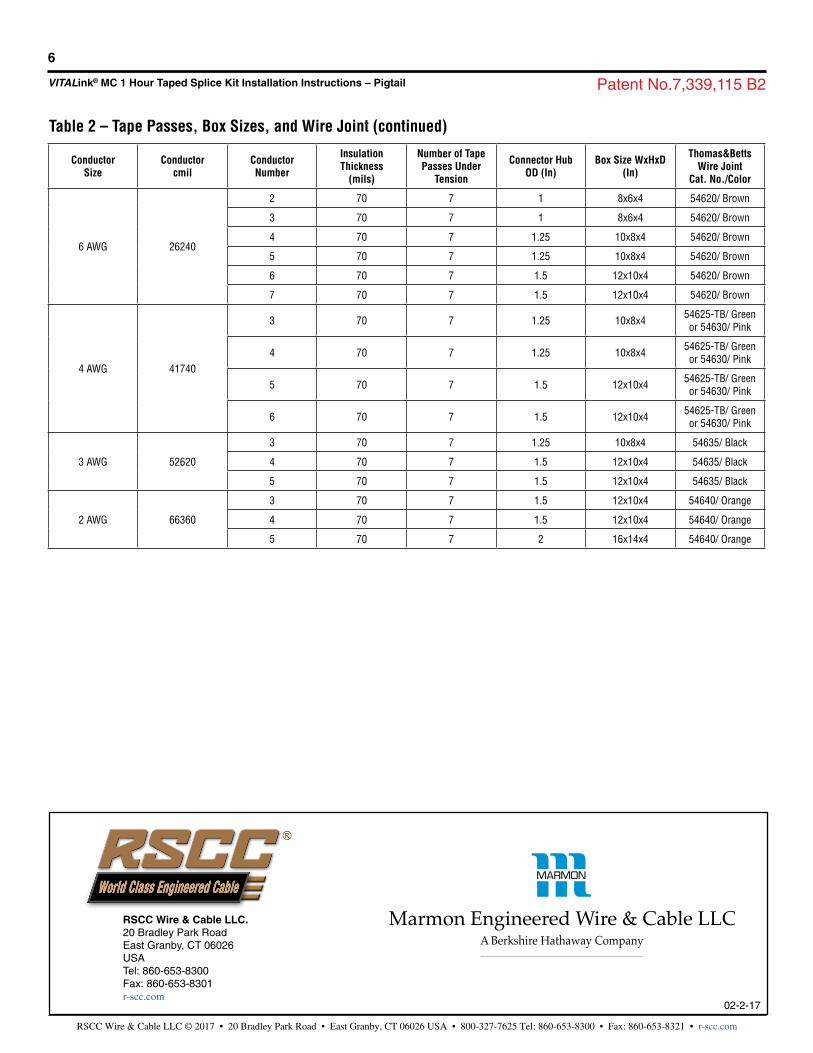
6 AWG 26240
2 70 7 1 8x6x4 54620/ Brown
3 70 7 1 8x6x4 54620/ Brown
4 70 7 1.25 10x8x4 54620/ Brown
5 70 7 1.25 10x8x4 54620/ Brown
6 70 7 1.5 12x10x4 54620/ Brown
7 70 7 1.5 12x10x4 54620/ Brown
4 AWG 41740
3 70 7 1.25 10x8x4 54625-TB/ Green or 54630/ Pink
4 70 7 1.25 10x8x4 54625-TB/ Green or 54630/ Pink
5 70 7 1.5 12x10x4 54625-TB/ Green or 54630/ Pink
6 70 7 1.5 12x10x4 54625-TB/ Green or 54630/ Pink
3 AWG 52620
3 70 7 1.25 10x8x4 54635/ Black
4 70 7 1.5 12x10x4 54635/ Black
5 70 7 1.5 12x10x4 54635/ Black
2 AWG 66360
3 70 7 1.5 12x10x4 54640/ Orange
4 70 7 1.5 12x10x4 54640/ Orange
5 70 7 2 16x14x4 54640/ Orange
Table 2 – Tape Passes, Box Sizes, and Wire Joint (continued)