Embed Size (px)
Citation preview
VMC1
Video Security Intercom System for the Home
Rough - In Instructions
USA & Canada (800) 421-1587 & (800) 392-0123(760) 438-7000 - Toll Free FAX (800) 468-1340
www.linearcorp.com
POWER BAND MEM ALARM DOWN UP
1 2 3 4 5 5 ME-UP+
TUNER
AUX MUSIC
RADIO FILTER
GATE STATUS
AUX OUTPUT 1
AUX OUTPUT 2
- +VOLUME
AUX 1 AUX 2 INPUT FILTER
VID 1 VID 2 VID 3 LOCK
PRIV MON MUS
CLEAR HOUSE DOOR AUX
5 6 7
1 2 3 4
Keep this manual in a safe place for future reference.To replace this manual, download available from Linear Web site:www.linearcorp.com
Read Instructions - All safety and operating instructions should be read before installing or operating the VMC1 Video Intercom system.Retain Instructions - The safety and operating instructions should be retained for future reference. Heed Warnings - All warnings on the appliance and in the operating instructions should be adhered to. Follow Instructions - All operating and use instructions should be followed. Water and Moisture - The appliance should not be used near water - for example: near bathtub, washbowl, kitchen sink, laundry tub, in a wet basement, or near a swimming pool, and the like. Doing so can create fire or shock hazards and impair the warranty. Attachments - Do not use attachments not recommended by the product manufacturer as they may cause hazards. Ventilation - The appliance should be situated so that its location or position does not interfere with its proper ventilation. For example, the appliance should not be situated on a bed, sofa, rug, or similar surface that may block the ventilation openings: or, placed in a built in installation, such as a bookcase or cabinet that may impede the flow of air to the ventilation openings.Heat - The appliance should be situated away from heat sources such as radiators, heat registers, stoves, or other appliances (including amplifiers) that produce heat. Power Sources - The appliance should be connected to a power supply only of the type described in the operating instructions or as marked on the appliance. Grounding or Polarization - Precautions should be taken so that the grounding or polarization means of an appliance is not defeated.
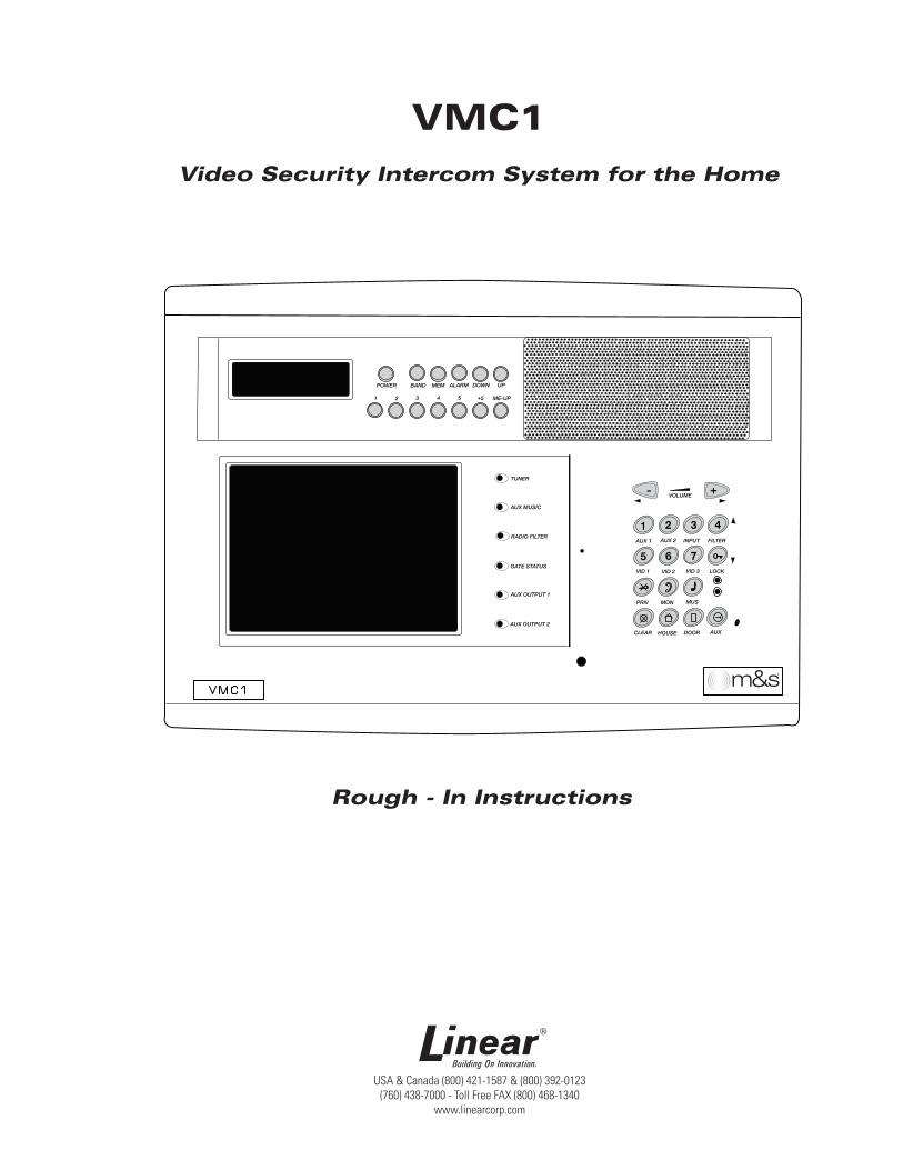
Power Lines - Locate outdoor antennas away from power lines. Outdoor Antenna Grounding - If an outside antenna is connected to the receiver, be sure the antenna system is grounded so as to provide some protection against voltage surges and built up static charges. Section 810 of the National Electrical Code, ANSI/NFPA No. 70 1984, provides information with respect to proper grounding of the mast and supporting structure, grounding of the lead in wire to an antenna discharge unit, size of grounding conductors, location of antenna discharge unit, connection to grounding electrodes, and requirements for the grounding electrode (see fi gure).Object and Liquid Entry - Never push objects of any kind into this product through openings as they may touch dangerous voltage points or short out parts that could result in a fi re or electric shock. Never spill liquid of any kind on the product.
Servicing - The user should not attempt to service the appliance beyond that described in the operating instructions. All other servicing should be referred to qualifi ed service personnel. Damage Requiring Service - The appliance should be serviced by qualifi ed service personnel when:• The power supply cord or the plug
has been damaged; or Objects have fallen, or liquid has been spilled into the appliance; or
• The appliance has been exposed to rain; or
• The appliance does not appear to operate normally or exhibits a marked change in performance; or
• The appliance has been dropped, or the enclosure damaged.
When the product exhibits a distinct change in performance - this indicates a need for service.Replacement Parts - When replacement parts are required, be sure the service technician has used replacement parts specifi ed by the manufacturer or have the same characteristics as the original part. Unauthorized substitutions may result in fi re, electric shock, or other hazards.Safety Check - Upon completion of any service or repairs to this product, ask the service technician to perform safety checks to determine that the product is in proper operating condition.Wall or Ceiling Mounting - The product should be mounted to a wall or ceiling only as recommended by the manufacturer.
IMPORTANT SAFETY INSTRUCTIONSSHOCK HAZARD
This sign alerts user about un-insulated “dangerous voltage” that poses risk of electric shock.
CAUTION!
This sign warns user about important operating, maintenance, and servicing instructions for
this product.
1
✔ DO ensure that all instructions have been followed before power is applied to system. The installation shall be carried out in accordance with all applicable installation rules. ✔ DO use only Cat-5 & RG-6 and specifi ed wires called out in these instructions. The cable is designed and constructed with electrical specifi cations necessary for proper audio performance. ✔ DO use only a damp cloth to clean the exterior plastics on the VMC1 Master Station and Room Stations. ✔ DO NOT use liquid or aerosols. ✔ DO make gradual bends of the cable where necessary -- no sharper than 1” radius. ✔ DO dress the cables neatly with cable ties or Velcro™ wraps. Use loose or moderate pressure. ✔ DO use cable-pulling lubricant only for cable runs that may otherwise require great force to install. When cable lubricant is used, read the instructions to be sure it is compatible with the cable jacket material (PVC or FEP). ✔ DO avoid stressing cable conductors, limit pulling tension to 25 pounds or less as specifi ed by EIA/TIA-568A standard. Pull cables gradually and with constant tension, taking care not to crush or pinch bundles. ✔ DO use grommets to protect the cable where passing through metal studs or anything that can possibly damage them. ✔ DO test every installed cable run with a cable tester. “Toning” alone is not acceptable. ✔ DO label every termination point. Use a unique identifi er for each cable run. It will make moves, adds, changes, and troubleshooting easier. ✔ DO support horizontal cable bundles using board supports, J-hooks, or cable trays. ✔ DO have signal cables cross at right angles to power cables to minimize induced interference. ✔ DO always obey all local and national fi re and building codes. Be sure to “fi re-stop” all cables that penetrate a fi re-wall. Use plenum-rated cable where mandated. ✔ DO have a licensed electrician to run a 120 VAC line from A DEDICATED 15-AMP BREAKER to the VMC1 power supply. ✔ DO Use Cat-5 wire for all VMC1 wire runs. ✔ DO label all wire runs. Connecting the wires to the VMC1 master, room station, or door station incorrectly may result in system damage. ✔ DO NOT STAPLE CABLES. Staples cause shorts.
✔ DO NOT SPLICE CABLES. Splices are unreliable and defeat the signal isolation properties of the cable. ✔ DO keep cables at least 18 inches from fl uorescent light fi xtures, Dimmer controls, and all other wiring. This includes AC wiring, security cable, and other control wires. These can cause a “hum” or “buzzing” sound. ✔ DO keep cables away from objects such as heating and air conditioning ducts, metal construction plates, and anything else with sharp edges that can damage the cables. ✔ DO follow the grounding and bonding requirements established by Electrical Code TIA standard 607, and equipment manufacturer’s specifi cations. ✔ DO NOT locate the VMC1 Master Station or Room Stations on an exterior wall. ✔ DO NOT locate the VMC1 Master Station or Room Stations in any wall cavity with any other electrical wiring in the cavity. ✔ DO NOT attach non line-level audio devices or non M&S authorized equipment to the system. ✔ DO NOT power up Master Station until all stations are connected. ✔ DO NOT splice or repair cables damaged during wire pulling, install a new cable. ✔ DO NOT coil or bundle the cables. This can cause electronic feedback. ✔ DO NOT over-tighten the screws for the stations or the intercom Master Station to prevent cracking. ✔ DO NOT install any station or speaker cables inside the 120 VAC transformer enclosure. ✔ DO NOT tie cables to electrical conduits or lay cables on electrical fi xtures. ✔ DO NOT allow the cable to be sharply bent or kinked at any time. ✔ DO NOT install cables “taut” anywhere. Good installation should have cables loose, but never sagging. ✔ DO NOT run signal and power cables parallel without adequate separation to minimize interference. ✔ DO NOT exert more than 25 pounds of tension on 4-pair cables. ✔ DO NOT step on Cat-5 cable during installation. ✔ DO NOT overtighten the cable ties, apply cable ties loosely, with random spacing. ✔ DO NOT untwist the wire pairs in Cat-5 cable more than 1/2” to avoid crosstalk.
IMPORTANT DO’S & DON’TS
Keep this manual in a safe place for future reference.To replace this manual, download available from Linear Web site:www.linearcorp.com
2
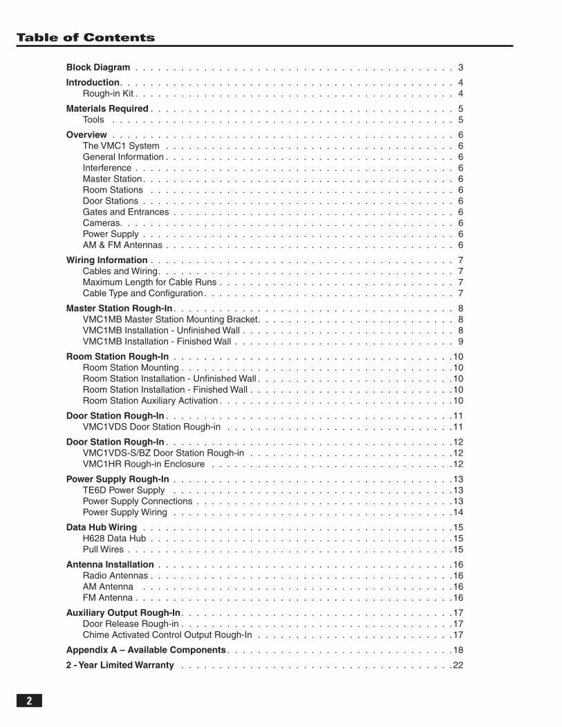
Table of Contents
Block Diagram . . . . . . . . . . . . . . . . . . . . . . . . . . . . . . . . . . . . . . . . . . 3
Introduction . . . . . . . . . . . . . . . . . . . . . . . . . . . . . . . . . . . . . . . . . . . . 4Rough-in Kit . . . . . . . . . . . . . . . . . . . . . . . . . . . . . . . . . . . . . . . . . . 4
Materials Required . . . . . . . . . . . . . . . . . . . . . . . . . . . . . . . . . . . . . . . . 5Tools . . . . . . . . . . . . . . . . . . . . . . . . . . . . . . . . . . . . . . . . . . . . . 5
Overview . . . . . . . . . . . . . . . . . . . . . . . . . . . . . . . . . . . . . . . . . . . . . 6The VMC1 System . . . . . . . . . . . . . . . . . . . . . . . . . . . . . . . . . . . . . . 6General Information . . . . . . . . . . . . . . . . . . . . . . . . . . . . . . . . . . . . . . 6Interference . . . . . . . . . . . . . . . . . . . . . . . . . . . . . . . . . . . . . . . . . . 6Master Station . . . . . . . . . . . . . . . . . . . . . . . . . . . . . . . . . . . . . . . . . 6Room Stations . . . . . . . . . . . . . . . . . . . . . . . . . . . . . . . . . . . . . . . . 6Door Stations . . . . . . . . . . . . . . . . . . . . . . . . . . . . . . . . . . . . . . . . . 6Gates and Entrances . . . . . . . . . . . . . . . . . . . . . . . . . . . . . . . . . . . . . 6Cameras. . . . . . . . . . . . . . . . . . . . . . . . . . . . . . . . . . . . . . . . . . . . 6Power Supply . . . . . . . . . . . . . . . . . . . . . . . . . . . . . . . . . . . . . . . . . 6AM & FM Antennas . . . . . . . . . . . . . . . . . . . . . . . . . . . . . . . . . . . . . . 6
Wiring Information . . . . . . . . . . . . . . . . . . . . . . . . . . . . . . . . . . . . . . . . 7Cables and Wiring . . . . . . . . . . . . . . . . . . . . . . . . . . . . . . . . . . . . . . . 7Maximum Length for Cable Runs . . . . . . . . . . . . . . . . . . . . . . . . . . . . . . . 7Cable Type and Confi guration . . . . . . . . . . . . . . . . . . . . . . . . . . . . . . . . . 7
Master Station Rough-In . . . . . . . . . . . . . . . . . . . . . . . . . . . . . . . . . . . . . 8VMC1MB Master Station Mounting Bracket . . . . . . . . . . . . . . . . . . . . . . . . . . 8VMC1MB Installation - Unfi nished Wall . . . . . . . . . . . . . . . . . . . . . . . . . . . . 8VMC1MB Installation - Finished Wall . . . . . . . . . . . . . . . . . . . . . . . . . . . . . 9
Room Station Rough-In . . . . . . . . . . . . . . . . . . . . . . . . . . . . . . . . . . . . .10Room Station Mounting . . . . . . . . . . . . . . . . . . . . . . . . . . . . . . . . . . . .10Room Station Installation - Unfi nished Wall . . . . . . . . . . . . . . . . . . . . . . . . . .10Room Station Installation - Finished Wall . . . . . . . . . . . . . . . . . . . . . . . . . . .10Room Station Auxiliary Activation . . . . . . . . . . . . . . . . . . . . . . . . . . . . . . .10
Door Station Rough-In . . . . . . . . . . . . . . . . . . . . . . . . . . . . . . . . . . . . . .11VMC1VDS Door Station Rough-in . . . . . . . . . . . . . . . . . . . . . . . . . . . . . .11
Door Station Rough-In . . . . . . . . . . . . . . . . . . . . . . . . . . . . . . . . . . . . . .12VMC1VDS-S/BZ Door Station Rough-in . . . . . . . . . . . . . . . . . . . . . . . . . . .12VMC1HR Rough-in Enclosure . . . . . . . . . . . . . . . . . . . . . . . . . . . . . . . .12
Power Supply Rough-In . . . . . . . . . . . . . . . . . . . . . . . . . . . . . . . . . . . . .13TE6D Power Supply . . . . . . . . . . . . . . . . . . . . . . . . . . . . . . . . . . . . .13Power Supply Connections . . . . . . . . . . . . . . . . . . . . . . . . . . . . . . . . . .13Power Supply Wiring . . . . . . . . . . . . . . . . . . . . . . . . . . . . . . . . . . . . .14
Data Hub Wiring . . . . . . . . . . . . . . . . . . . . . . . . . . . . . . . . . . . . . . . . .15H628 Data Hub . . . . . . . . . . . . . . . . . . . . . . . . . . . . . . . . . . . . . . . .15Pull Wires . . . . . . . . . . . . . . . . . . . . . . . . . . . . . . . . . . . . . . . . . . .15
Antenna Installation . . . . . . . . . . . . . . . . . . . . . . . . . . . . . . . . . . . . . . .16Radio Antennas . . . . . . . . . . . . . . . . . . . . . . . . . . . . . . . . . . . . . . . .16AM Antenna . . . . . . . . . . . . . . . . . . . . . . . . . . . . . . . . . . . . . . . . .16FM Antenna . . . . . . . . . . . . . . . . . . . . . . . . . . . . . . . . . . . . . . . . . .16
Auxiliary Output Rough-In . . . . . . . . . . . . . . . . . . . . . . . . . . . . . . . . . . . .17Door Release Rough-in . . . . . . . . . . . . . . . . . . . . . . . . . . . . . . . . . . . .17Chime Activated Control Output Rough-In . . . . . . . . . . . . . . . . . . . . . . . . . .17
Appendix A – Available Components . . . . . . . . . . . . . . . . . . . . . . . . . . . . . .18
2 - Year Limited Warranty . . . . . . . . . . . . . . . . . . . . . . . . . . . . . . . . . . . .22
3
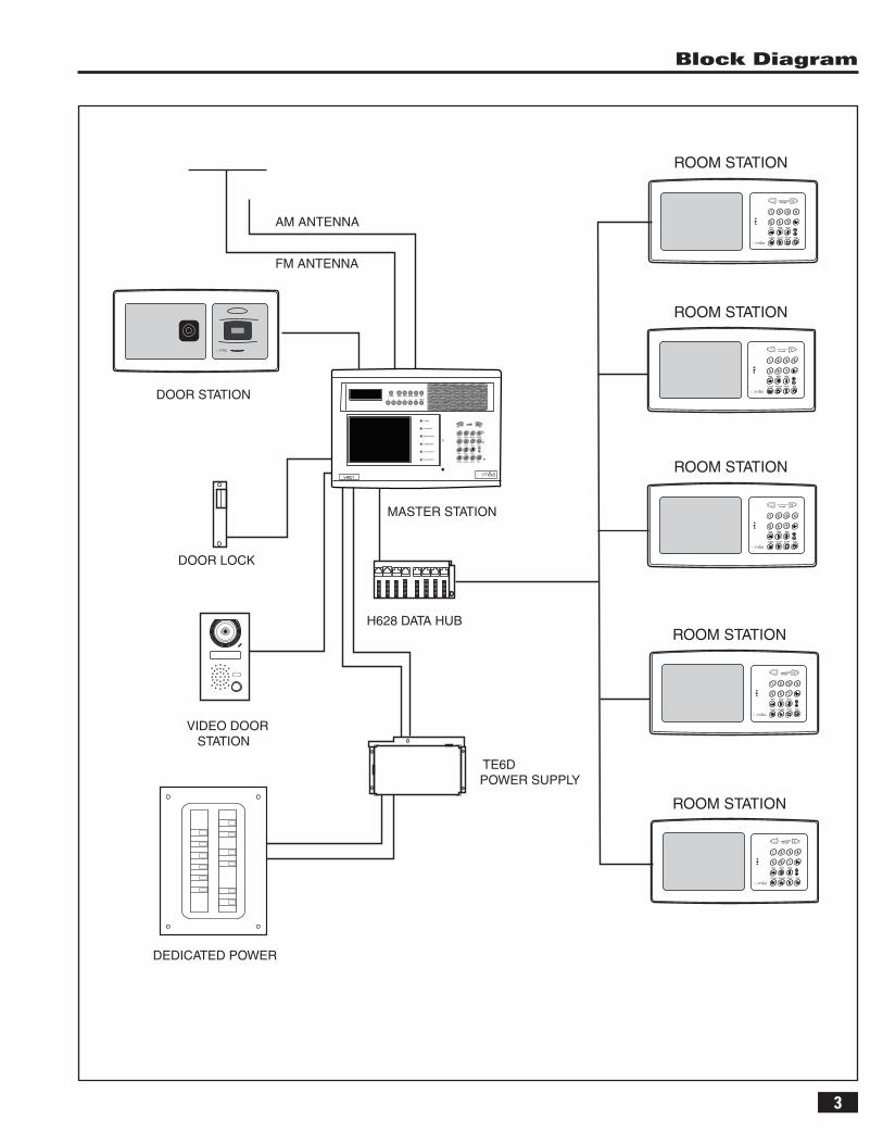
Block Diagram
- +
1
VOLUME
PRIV MON MUS
CLEAR HOUSE DOOR AUX
2 3 4
5 6 7AM ANTENNA
FM ANTENNA
MASTER STATION
TE6DPOWER SUPPLY
H628 DATA HUB
ROOM STATION
DOOR STATION
DEDICATED POWER
VIDEO DOOR STATION
DOOR LOCK
- +
1
VOLUME
PRIV MON MUS
CLEAR HOUSE DOOR AUX
2 3 4
5 6 7
- +
1
VOLUME
PRIV MON MUS
CLEAR HOUSE DOOR AUX
2 3 4
5 6 7
- +
1
VOLUME
PRIV MON MUS
CLEAR HOUSE DOOR AUX
2 3 4
5 6 7
- +
1
VOLUME
PRIV MON MUS
CLEAR HOUSE DOOR AUX
2 3 4
5 6 7
ROOM STATION
ROOM STATION
ROOM STATION
ROOM STATION
POWER BAND MEM ALARM DOWN UP
1 2 3 4 5 5 ME-UP+
TUNER
AUX MUSIC
RADIO FILTER
GATE STATUS
AUX OUTPUT 1
AUX OUTPUT 2
- +VOLUME
AUX 1 AUX 2 INPUT FILTER
VID 1 VID 2 VID 3 LOCK
PRIV MON MUS
CLEAR HOUSE DOOR AUX
3 4
5 6 7
1 2
4
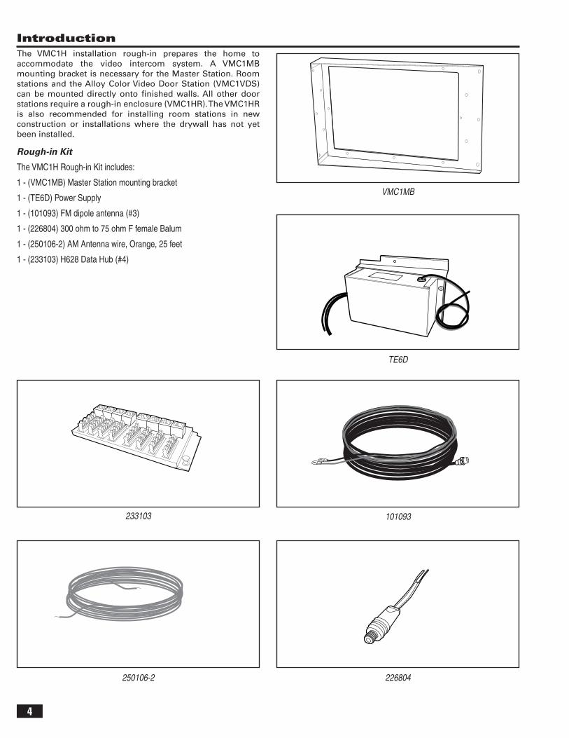
Introduction
VMC1MB
TE6D
101093
226804250106-2
233103
The VMC1H installation rough-in prepares the home to accommodate the video intercom system. A VMC1MB mounting bracket is necessary for the Master Station. Room stations and the Alloy Color Video Door Station (VMC1VDS) can be mounted directly onto fi nished walls. All other door stations require a rough-in enclosure (VMC1HR). The VMC1HR is also recommended for installing room stations in new construction or installations where the drywall has not yet been installed.
Rough-in Kit
The VMC1H Rough-in Kit includes:
1 - (VMC1MB) Master Station mounting bracket
1 - (TE6D) Power Supply
1 - (101093) FM dipole antenna (#3)
1 - (226804) 300 ohm to 75 ohm F female Balum
1 - (250106-2) AM Antenna wire, Orange, 25 feet
1 - (233103) H628 Data Hub (#4)
5
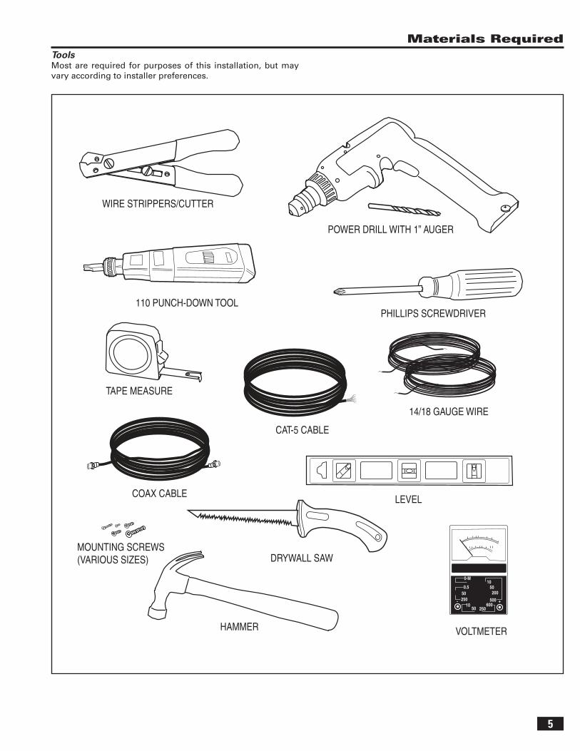
Materials RequiredTools Most are required for purposes of this installation, but may vary according to installer preferences.
POWER DRILL WITH 1” AUGER
WIRE STRIPPERS/CUTTER
TAPE MEASURE
PHILLIPS SCREWDRIVER
14/18 GAUGE WIRE
110 PUNCH-DOWN TOOL
CAT-5 CABLE
DRYWALL SAW
HAMMER
LEVEL
0-M
0.510
50200
50050250
1050 250
600+-
MOUNTING SCREWS (VARIOUS SIZES)
VOLTMETER
COAX CABLE
6
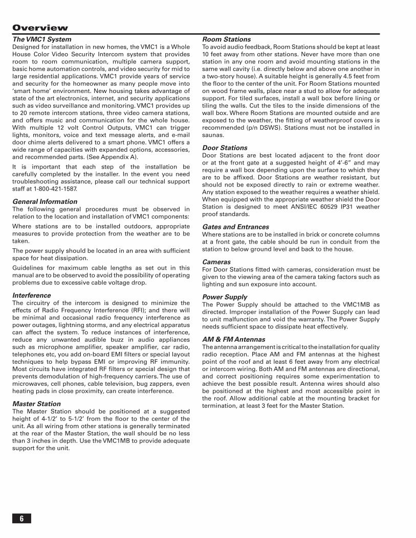
OverviewThe VMC1 SystemDesigned for installation in new homes, the VMC1 is a Whole House Color Video Security Intercom system that provides room to room communication, multiple camera support, basic home automation controls, and video security for mid to large residential applications. VMC1 provide years of service and security for the homeowner as many people move into ‘smart home’ environment. New housing takes advantage of state of the art electronics, internet, and security applications such as video surveillance and monitoring. VMC1 provides up to 20 remote intercom stations, three video camera stations, and offers music and communication for the whole house. With multiple 12 volt Control Outputs, VMC1 can trigger lights, monitors, voice and text message alerts, and e-mail door chime alerts delivered to a smart phone. VMC1 offers a wide range of capacities with expanded options, accessories, and recommended parts. (See Appendix A).
It is important that each step of the installation be carefully completed by the installer. In the event you need troubleshooting assistance, please call our technical support staff at 1-800-421-1587.
General InformationThe following general procedures must be observed in relation to the location and installation of VMC1 components:
Where stations are to be installed outdoors, appropriate measures to provide protection from the weather are to be taken.
The power supply should be located in an area with suffi cient space for heat dissipation.
Guidelines for maximum cable lengths as set out in this manual are to be observed to avoid the possibility of operating problems due to excessive cable voltage drop.
InterferenceThe circuitry of the intercom is designed to minimize the effects of Radio Frequency Interference (RFI); and there will be minimal and occasional radio frequency interference as power outages, lightning storms, and any electrical apparatus can affect the system. To reduce instances of interference, reduce any unwanted audible buzz in audio appliances such as microphone amplifi er, speaker amplifi er, car radio, telephones etc, you add on-board EMI fi lters or special layout techniques to help bypass EMI or improving RF immunity. Most circuits have integrated RF fi lters or special design that prevents demodulation of high-frequency carriers. The use of microwaves, cell phones, cable television, bug zappers, even heating pads in close proximity, can create interference.
Master StationThe Master Station should be positioned at a suggested height of 4-1/2’ to 5-1/2’ from the fl oor to the center of the unit. As all wiring from other stations is generally terminated at the rear of the Master Station, the wall should be no less than 3 inches in depth. Use the VMC1MB to provide adequate support for the unit.
Room StationsTo avoid audio feedback, Room Stations should be kept at least 10 feet away from other stations. Never have more than one station in any one room and avoid mounting stations in the same wall cavity (i.e. directly below and above one another in a two-story house). A suitable height is generally 4.5 feet from the fl oor to the center of the unit. For Room Stations mounted on wood frame walls, place near a stud to allow for adequate support. For tiled surfaces, install a wall box before lining or tiling the walls. Cut the tiles to the inside dimensions of the wall box. Where Room Stations are mounted outside and are exposed to the weather, the fi tting of weatherproof covers is recommended (p/n DSWS). Stations must not be installed in saunas.
Door StationsDoor Stations are best located adjacent to the front door or at the front gate at a suggested height of 4’-6” and may require a wall box depending upon the surface to which they are to be affi xed. Door Stations are weather resistant, but should not be exposed directly to rain or extreme weather. Any station exposed to the weather requires a weather shield. When equipped with the appropriate weather shield the Door Station is designed to meet ANSI/IEC 60529 IP31 weather proof standards.
Gates and EntrancesWhere stations are to be installed in brick or concrete columns at a front gate, the cable should be run in conduit from the station to below ground level and back to the house.
CamerasFor Door Stations fi tted with cameras, consideration must be given to the viewing area of the camera taking factors such as lighting and sun exposure into account.
Power Supply The Power Supply should be attached to the VMC1MB as directed. Improper installation of the Power Supply can lead to unit malfunction and void the warranty. The Power Supply needs suffi cient space to dissipate heat effectively.
AM & FM AntennasThe antenna arrangement is critical to the installation for quality radio reception. Place AM and FM antennas at the highest point of the roof and at least 6 feet away from any electrical or intercom wiring. Both AM and FM antennas are directional, and correct positioning requires some experimentation to achieve the best possible result. Antenna wires should also be positioned at the highest and most accessible point in the roof. Allow additional cable at the mounting bracket for termination, at least 3 feet for the Master Station.
7
Wiring InformationCables and WiringExcellent locations to run cables include:
• Roof space• False ceilings/ bulkhead area• Through and/or around external walls• Under fl oors (subject to access being available)• Underground in conduit
✓ NOTE: Keep Intercom cables far from any AC wiring. Avoid running intercom cable in parallel to AC or any other type of wiring. Avoid placing joins or splices in cables. Locate cables where there is access for future servicing.
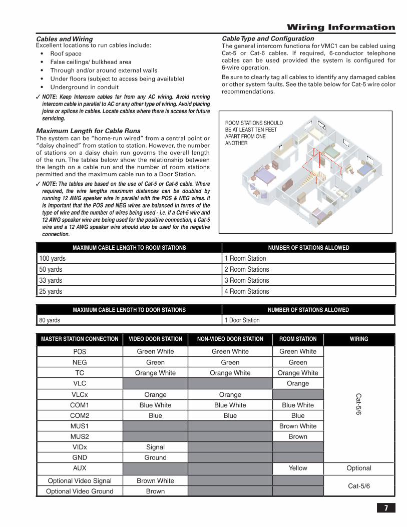
Maximum Length for Cable RunsThe system can be “home-run wired” from a central point or “daisy chained” from station to station. However, the number of stations on a daisy chain run governs the overall length of the run. The tables below show the relationship between the length on a cable run and the number of room stations permitted and the maximum cable run to a Door Station.
✓ NOTE: The tables are based on the use of Cat-5 or Cat-6 cable. Where required, the wire lengths maximum distances can be doubled by running 12 AWG speaker wire in parallel with the POS & NEG wires. It is important that the POS and NEG wires are balanced in terms of the type of wire and the number of wires being used - i.e. if a Cat-5 wire and 12 AWG speaker wire are being used for the positive connection, a Cat-5 wire and a 12 AWG speaker wire should also be used for the negative connection.
MAXIMUM CABLE LENGTH TO ROOM STATIONS NUMBER OF STATIONS ALLOWED
100 yards 1 Room Station
50 yards 2 Room Stations
33 yards 3 Room Stations
25 yards 4 Room Stations
Cable Type and Confi gurationThe general intercom functions for VMC1 can be cabled using Cat-5 or Cat-6 cables. If required, 6-conductor telephone cables can be used provided the system is confi gured for 6-wire operation.
Be sure to clearly tag all cables to identify any damaged cables or other system faults. See the table below for Cat-5 wire color recommendations.
ROOM STATIONS SHOULDBE AT LEAST TEN FEETAPART FROM ONE ANOTHER
MAXIMUM CABLE LENGTH TO DOOR STATIONS NUMBER OF STATIONS ALLOWED
80 yards 1 Door Station
MASTER STATION CONNECTION VIDEO DOOR STATION NON-VIDEO DOOR STATION ROOM STATION WIRING
POS Green White Green White Green White
Cat-5/6
NEG Green Green Green
TC Orange White Orange White Orange White
VLC Orange
VLCx Orange Orange
COM1 Blue White Blue White Blue White
COM2 Blue Blue Blue
MUS1 Brown White
MUS2 Brown
VIDx Signal
GND Ground
AUX Yellow Optional
Optional Video Signal Brown WhiteCat-5/6
Optional Video Ground Brown
8
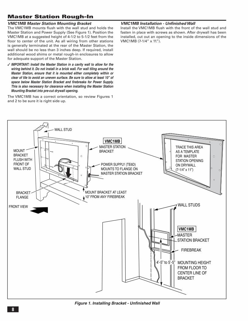
Master Station Rough-InVMC1MB Master Station Mounting BracketThe VMC1MB mounts fl ush with the wall stud and holds the Master Station and Power Supply (See Figure 1). Position the VMC1MB at a suggested height of 4-1/2 to 5-1/2 feet from the fl oor to center of the unit. As all wiring from other stations is generally terminated at the rear of the Master Station, the wall should be no less than 3 inches deep. If required, install additional wood shims or metal rough-in enclosures to allow for adequate support of the Master Station.
✓ IMPORTANT: Install the Master Station in a cavity wall to allow for the wiring behind it. Do not install in a brick wall. For wall tiling around the Master Station, ensure that it is mounted either completely within or clear of tile to avoid an uneven surface. Be sure to allow at least 10” of space below Master Station Bracket and fi rebreaks for Power Supply. This is also necessary for clearance when installing the Master Station Mounting Bracket into pre-cut drywall opening.
The VMC1MB has a correct orientation, so review Figures 1 and 2 to be sure it is right side up.
VMC1MB Installation - Unfi nished WallInstall the VMC1MB fl ush with the front of the wall stud and fasten in place with screws as shown. After drywall has been installed, cut out an opening to the inside dimensions of the VMC1MB (7-1/4” x 11.”).
Figure 1. Installing Bracket - Unfi nished Wall
WALL STUD
POWER SUPPLY (TE6D)MOUNTS TO FLANGE ONMASTER STATION BRACKET
BRACKETFLANGE
MASTER STATION BRACKET MOUNT
BRACKETFLUSH WITHFRONT OFWALL STUD
MOUNT BRACKET AT LEAST10” FROM ANY FIREBREAK
WALL STUDS
MOUNTING HEIGHTFROM FLOOR TOCENTER LINE OFBRACKET
MASTER STATION BRACKET
4’-5” to 5’-5”
FIREBREAK
VMC1MB
VMC1MB
FRONT VIEW
TRACE THIS AREAAS A TEMPLATEFOR MASTERSTATION OPENINGON DRYWALL(7-1/4” x 11”)
9
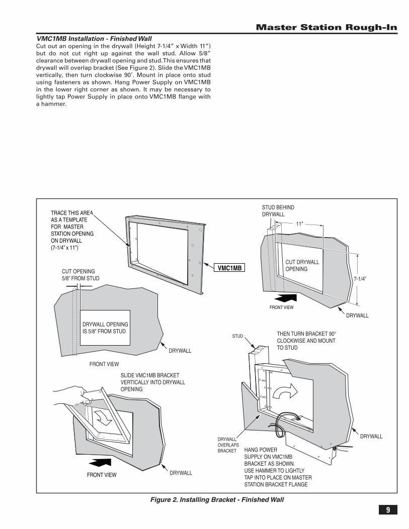
Master Station Rough-InVMC1MB Installation - Finished WallCut out an opening in the drywall (Height 7-1/4” x Width 11”) but do not cut right up against the wall stud. Allow 5/8” clearance between drywall opening and stud. This ensures that drywall will overlap bracket (See Figure 2). Slide the VMC1MB vertically, then turn clockwise 90˚. Mount in place onto stud using fasteners as shown. Hang Power Supply on VMC1MB in the lower right corner as shown. It may be necessary to lightly tap Power Supply in place onto VMC1MB fl ange with a hammer.
Figure 2. Installing Bracket - Finished Wall
FRONT VIEW
FRONT VIEW
7-1/4”
FRONT VIEW
CUT OPENING5/8” FROM STUD
STUD BEHIND DRYWALL
DRYWALLOVERLAPSBRACKET HANG POWER
SUPPLY ON VMC1MBBRACKET AS SHOWN.USE HAMMER TO LIGHTLYTAP INTO PLACE ON MASTERSTATION BRACKET FLANGE
DRYWALL
STUD
DRYWALL
DRYWALL
DRYWALL
DRYWALL OPENINGIS 5/8” FROM STUD
CUT DRYWALLOPENING
11”
SLIDE VMC1MB BRACKETVERTICALLY INTO DRYWALLOPENING
THEN TURN BRACKET 90° CLOCKWISE AND MOUNT TO STUD
TRACE THIS AREAAS A TEMPLATEFOR MASTERSTATION OPENINGON DRYWALL(7-1/4” x 11”)
VMC1MB
10
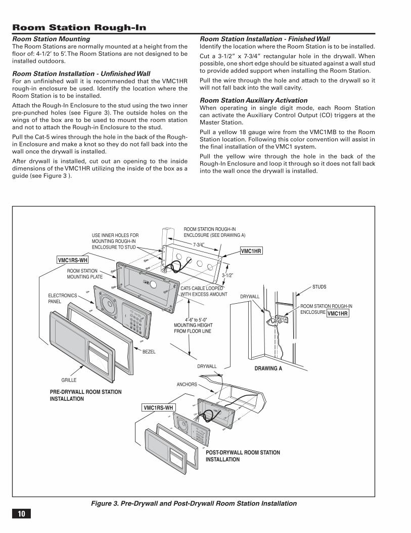
Room Station Rough-InRoom Station MountingThe Room Stations are normally mounted at a height from the fl oor of: 4-1/2’ to 5’. The Room Stations are not designed to be installed outdoors.
Room Station Installation - Unfi nished WallFor an unfi nished wall it is recommended that the VMC1HR rough-in enclosure be used. Identify the location where the Room Station is to be installed.
Attach the Rough-In Enclosure to the stud using the two inner pre-punched holes (see Figure 3). The outside holes on the wings of the box are to be used to mount the room station and not to attach the Rough-in Enclosure to the stud.
Pull the Cat-5 wires through the hole in the back of the Rough-in Enclosure and make a knot so they do not fall back into the wall once the drywall is installed.
After drywall is installed, cut out an opening to the inside dimensions of the VMC1HR utilizing the inside of the box as a guide (see Figure 3 ).
Room Station Installation - Finished WallIdentify the location where the Room Station is to be installed.
Cut a 3-1/2” x 7-3/4” rectangular hole in the drywall. When possible, one short edge should be situated against a wall stud to provide added support when installing the Room Station.
Pull the wire through the hole and attach to the drywall so it will not fall back into the wall cavity.
Room Station Auxiliary ActivationWhen operating in single digit mode, each Room Station can activate the Auxiliary Control Output (CO) triggers at the Master Station.
Pull a yellow 18 gauge wire from the VMC1MB to the Room Station location. Following this color convention will assist in the fi nal installation of the VMC1 system.
Pull the yellow wire through the hole in the back of the Rough-In Enclosure and loop it through so it does not fall back into the wall once the drywall is installed.
Figure 3. Pre-Drywall and Post-Drywall Room Station Installation
STUDS
MOUNTING HEIGHTFROM FLOOR LINE
4’-6” to 5’-0”
ROOM STATION ROUGH-INENCLOSURE (SEE DRAWING A)
7-3/4”
3-1/2”
USE INNER HOLES FOR MOUNTING ROUGH-IN ENCLOSURE TO STUD
CAT5 CABLE LOOPEDWITH EXCESS AMOUNT DRYWALL
-
+1VOLUME
PRIV
MON
MUSCLEARHOUSE
DOORAUX
23
45
67
PRE-DRYWALL ROOM STATIONINSTALLATION
DRAWING ADRYWALL
GRILLE
ELECTRONICS PANEL
ROOM STATION ROUGH-INENCLOSURE
ANCHORS
ROOM STATIONMOUNTING PLATE
POST-DRYWALL ROOM STATIONINSTALLATION
BEZEL
-
+1VOLUME
PRIV
MON
MUSCLEARHOUSE
DOORAUX
23
45
67
VMC1RS-WH
VMC1HR
VMC1RS-WH
VMC1HR
11
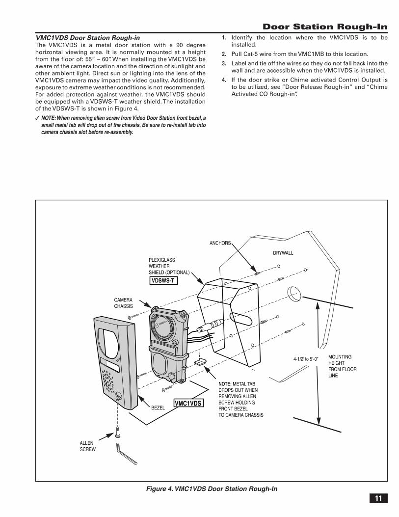
Door Station Rough-InVMC1VDS Door Station Rough-in The VMC1VDS is a metal door station with a 90 degree horizontal viewing area. It is normally mounted at a height from the fl oor of: 55” – 60”. When installing the VMC1VDS be aware of the camera location and the direction of sunlight and other ambient light. Direct sun or lighting into the lens of the VMC1VDS camera may impact the video quality. Additionally, exposure to extreme weather conditions is not recommended. For added protection against weather, the VMC1VDS should be equipped with a VDSWS-T weather shield. The installation of the VDSWS-T is shown in Figure 4.
✓ NOTE: When removing allen screw from Video Door Station front bezel, a small metal tab will drop out of the chassis. Be sure to re-install tab into camera chassis slot before re-assembly.
Figure 4. VMC1VDS Door Station Rough-In
1. Identify the location where the VMC1VDS is to be installed.
2. Pull Cat-5 wire from the VMC1MB to this location.
3. Label and tie off the wires so they do not fall back into the wall and are accessible when the VMC1VDS is installed.
4. If the door strike or Chime activated Control Output is to be utilized, see “Door Release Rough-in” and “Chime Activated CO Rough-in”.
DRYWALL
ANCHORS
CAMERA CHASSIS
PLEXIGLASSWEATHERSHIELD (OPTIONAL)
BEZEL
ALLENSCREW
MOUNTING HEIGHTFROM FLOOR LINE
NOTE: METAL TABDROPS OUT WHENREMOVING ALLENSCREW HOLDINGFRONT BEZELTO CAMERA CHASSIS
4-1/2’ to 5’-0”
VMC1VDS
VDSWS-T
12
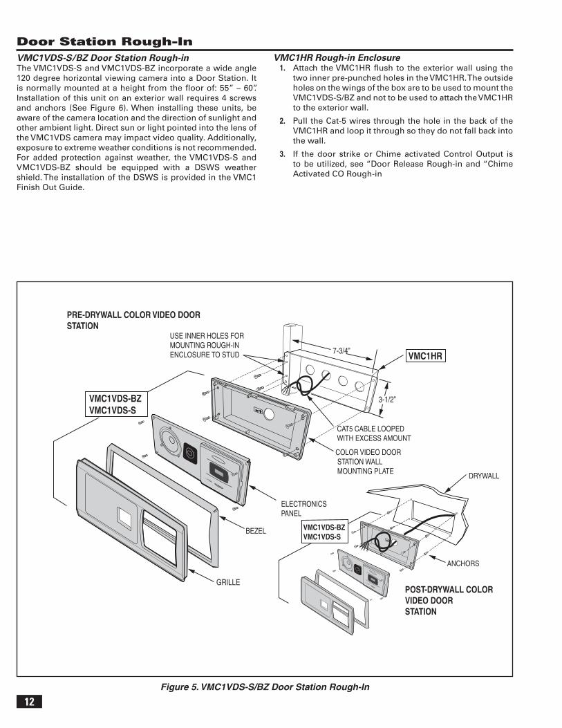
VMC1VDS-S/BZ Door Station Rough-in The VMC1VDS-S and VMC1VDS-BZ incorporate a wide angle 120 degree horizontal viewing camera into a Door Station. It is normally mounted at a height from the fl oor of: 55” – 60”. Installation of this unit on an exterior wall requires 4 screws and anchors (See Figure 6). When installing these units, be aware of the camera location and the direction of sunlight and other ambient light. Direct sun or light pointed into the lens of the VMC1VDS camera may impact video quality. Additionally, exposure to extreme weather conditions is not recommended. For added protection against weather, the VMC1VDS-S and VMC1VDS-BZ should be equipped with a DSWS weather shield. The installation of the DSWS is provided in the VMC1 Finish Out Guide.
Figure 5. VMC1VDS-S/BZ Door Station Rough-In
Door Station Rough-In
7-3/4”
3-1/2”
USE INNER HOLES FOR MOUNTING ROUGH-IN ENCLOSURE TO STUD
CAT5 CABLE LOOPEDWITH EXCESS AMOUNT
PRE-DRYWALL COLOR VIDEO DOORSTATION
DRYWALL
GRILLE
ELECTRONICS PANEL
ANCHORS
COLOR VIDEO DOOR STATION WALL MOUNTING PLATE
BEZEL
POST-DRYWALL COLOR VIDEO DOORSTATION
VMC1VDS-BZVMC1VDS-S
VMC1VDS-BZVMC1VDS-S
VMC1HR
VMC1HR Rough-in Enclosure1. Attach the VMC1HR fl ush to the exterior wall using the
two inner pre-punched holes in the VMC1HR. The outside holes on the wings of the box are to be used to mount the VMC1VDS-S/BZ and not to be used to attach the VMC1HR to the exterior wall.
2. Pull the Cat-5 wires through the hole in the back of the VMC1HR and loop it through so they do not fall back into the wall.
3. If the door strike or Chime activated Control Output is to be utilized, see “Door Release Rough-in and “Chime Activated CO Rough-in
13
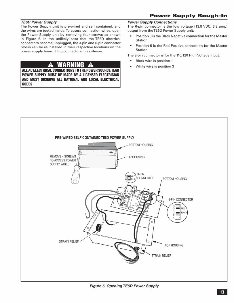
Power Supply Rough-InTE6D Power Supply The Power Supply unit is pre-wired and self contained, and the wires are tucked inside. To access connection wires, open the Power Supply unit by removing four screws as shown in Figure 6. In the unlikely case that the TE6D electrical connectors become unplugged, the 3-pin and 6-pin connector blocks can be re-installed in their respective locations on the power supply board. Plug connectors in as shown.
WARNING ALL AC ELECTRICAL CONNECTIONS TO THE POWER SOURCE TE6D POWER SUPPLY MUST BE MADE BY A LICENSED ELECTRICIAN AND MUST OBSERVE ALL NATIONAL AND LOCAL ELECTRICAL CODES
WHTBLK1
23
PRE-WIRED SELF CONTAINED TE6D POWER SUPPLY
TOP HOUSING
BOTTOM HOUSING
REMOVE 4 SCREWSTO ACCESS POWERSUPPLY WIRES
STRAIN RELIEF
STRAIN RELIEF
TOP HOUSING
BOTTOM HOUSING3-PIN CONNECTOR
6-PIN CONNECTOR
123456
RED
BLACK
Power Supply ConnectionsThe 6-pin connector is the low voltage (13.8 VDC, 3.8 amp) output from the TE6D Power Supply unit:
• Position 3 is the Black Negative connection for the Master Station
• Position 5 is the Red Positive connection for the Master Station
The 3-pin connector is for the 110/120 High Voltage input:
• Black wire is position 1
• White wire is position 3
Figure 6. Opening TE6D Power Supply
14
Power Supply Rough-In
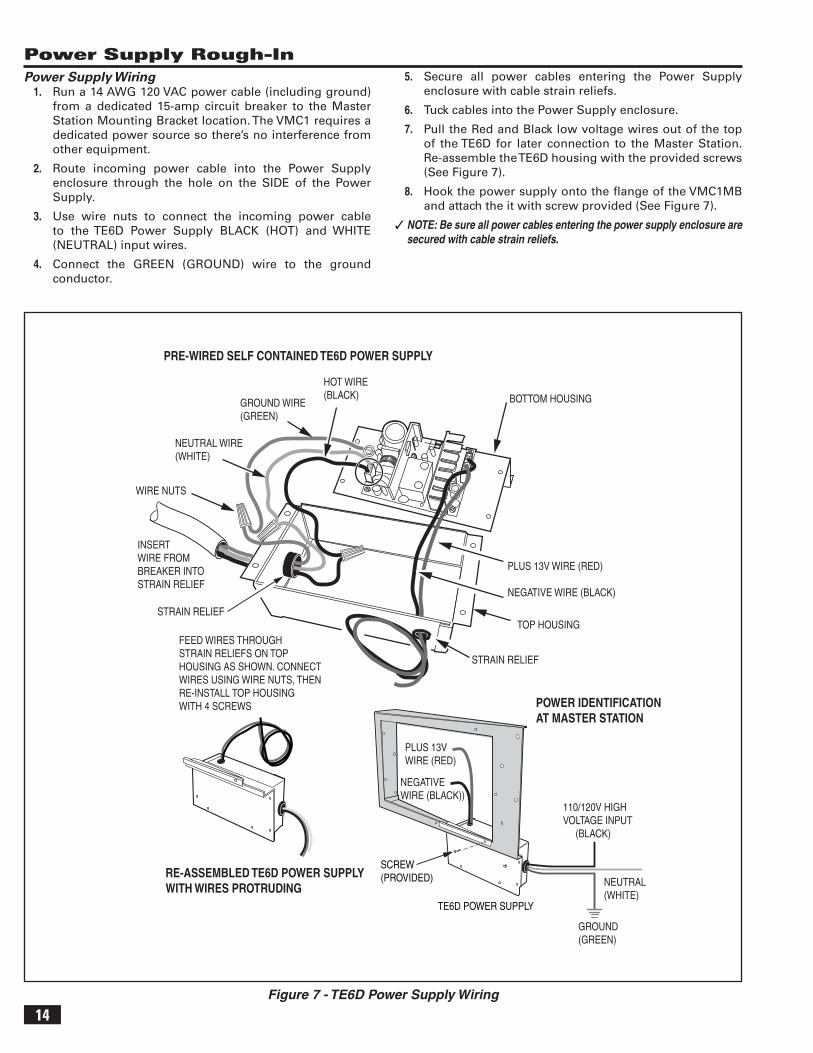
Figure 7 - TE6D Power Supply Wiring
Power Supply Wiring1. Run a 14 AWG 120 VAC power cable (including ground)
from a dedicated 15-amp circuit breaker to the Master Station Mounting Bracket location. The VMC1 requires a dedicated power source so there’s no interference from other equipment.
2. Route incoming power cable into the Power Supply enclosure through the hole on the SIDE of the Power Supply.
3. Use wire nuts to connect the incoming power cable to the TE6D Power Supply BLACK (HOT) and WHITE (NEUTRAL) input wires.
4. Connect the GREEN (GROUND) wire to the ground conductor.
5. Secure all power cables entering the Power Supply enclosure with cable strain reliefs.
6. Tuck cables into the Power Supply enclosure.
7. Pull the Red and Black low voltage wires out of the top of the TE6D for later connection to the Master Station. Re-assemble the TE6D housing with the provided screws (See Figure 7).
8. Hook the power supply onto the fl ange of the VMC1MB and attach the it with screw provided (See Figure 7).
✓ NOTE: Be sure all power cables entering the power supply enclosure are secured with cable strain reliefs.
GROUND WIRE (GREEN)
NEUTRAL WIRE(WHITE)
HOT WIRE(BLACK)
INSERT WIRE FROMBREAKER INTOSTRAIN RELIEF
WIRE NUTS
PRE-WIRED SELF CONTAINED TE6D POWER SUPPLY
FEED WIRES THROUGHSTRAIN RELIEFS ON TOPHOUSING AS SHOWN. CONNECTWIRES USING WIRE NUTS, THENRE-INSTALL TOP HOUSINGWITH 4 SCREWS
STRAIN RELIEF
STRAIN RELIEF
TOP HOUSING
BOTTOM HOUSING
PLUS 13V WIRE (RED)
NEGATIVE WIRE (BLACK)
RE-ASSEMBLED TE6D POWER SUPPLYWITH WIRES PROTRUDING
TE6D POWER SUPPLY
SCREW(PROVIDED) NEUTRAL
(WHITE)
GROUND(GREEN)
110/120V HIGH VOLTAGE INPUT (BLACK)
POWER IDENTIFICATION AT MASTER STATION
PLUS 13VWIRE (RED)
NEGATIVEWIRE (BLACK))
15
Data Hub Wiring
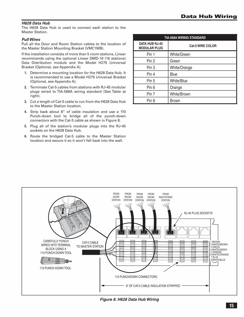
TIA-568A WIRING STANDARD
DATA HUB RJ-45 MODULAR PLUG
Cat-5 WIRE COLOR
Pin 1 White/Green
Pin 2 Green
Pin 3 White/Orange
Pin 4 Blue
Pin 5 White/Blue
Pin 6 Orange
Pin 7 White/Brown
Pin 8 Brown
Figure 8. H628 Data Hub Wiring
H628 Data HubThe H628 Data Hub is used to connect each station to the Master Station.
Pull WiresPull all the Door and Room Station cables to the location of the Master Station Mounting Bracket (VMC1MB).
If the installation consists of more than 5 room stations, Linear recommends using the optional Linear DMD-16 (16 stations) Data Distribution module and the Model H275 Universal Bracket (Optional, see Appendix A).
1. Determine a mounting location for the H628 Data Hub. It is recommended to use a Model H275 Universal Bracket (Optional, see Appendix A).
2. Terminate Cat-5 cables from stations with RJ-45 modular plugs wired to TIA-568A wiring standard (See Table at right).
3. Cut a length of Cat-5 cable to run from the H628 Data Hub to the Master Station location.
4. Strip back about 8” of cable insulation and use a 110 Punch-down tool to bridge all of the punch-down connectors with the Cat-5 cable as shown in Figure 8.
5. Plug all of the station’s modular plugs into the RJ-45 sockets on the H628 Data Hub.
6. Route the bridged Cat-5 cable to the Master Station location and secure it so it won’t fall back into the wall.
1 BROWN2 WHITE/BROWN3 GREEN4 WHITE/GREEN5 ORANGE
7 BLUE6 WHITE/ORANGE
8 WHITE/BLUE
CAT-5 CABLETO MASTER STATION
FROMDOOR
STATION
FROMROOM
STATION
FROMROOM
STATION
FROMROOM
STATION
FROMNIGHTSTAND
STATION
110 PUNCHDOWN CONNECTORS
110 PUNCH-DOWN TOOL
CAREFULLY PUNCHWIRES INTO TERMINAL
BLOCK USING A110 PUNCH-DOWN TOOL
RJ-45 PLUG SOCKETS
8” OF CAT-5 CABLE INSULATION STRIPPED
16
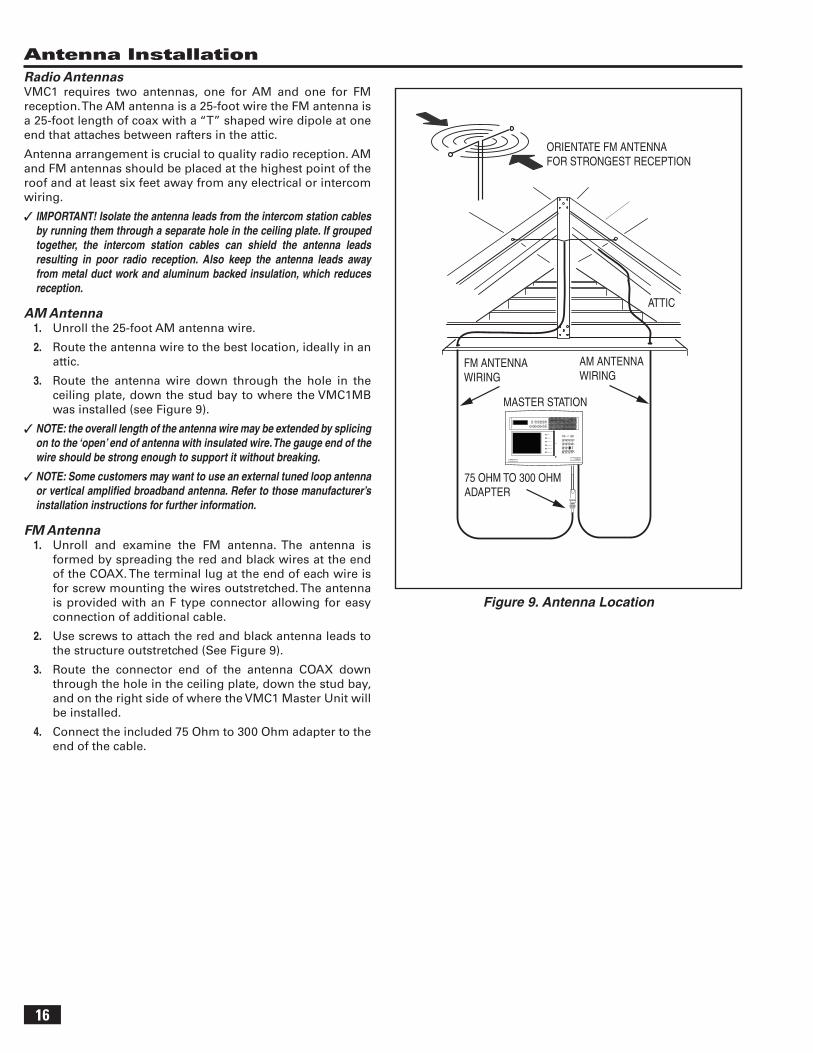
Antenna InstallationRadio AntennasVMC1 requires two antennas, one for AM and one for FM reception. The AM antenna is a 25-foot wire the FM antenna is a 25-foot length of coax with a “T” shaped wire dipole at one end that attaches between rafters in the attic.
Antenna arrangement is crucial to quality radio reception. AM and FM antennas should be placed at the highest point of the roof and at least six feet away from any electrical or intercom wiring.
✓ IMPORTANT! Isolate the antenna leads from the intercom station cables by running them through a separate hole in the ceiling plate. If grouped together, the intercom station cables can shield the antenna leads resulting in poor radio reception. Also keep the antenna leads away from metal duct work and aluminum backed insulation, which reduces reception.
AM Antenna 1. Unroll the 25-foot AM antenna wire.
2. Route the antenna wire to the best location, ideally in an attic.
3. Route the antenna wire down through the hole in the ceiling plate, down the stud bay to where the VMC1MB was installed (see Figure 9).
✓ NOTE: the overall length of the antenna wire may be extended by splicing on to the ‘open’ end of antenna with insulated wire. The gauge end of the wire should be strong enough to support it without breaking.
✓ NOTE: Some customers may want to use an external tuned loop antenna or vertical amplifi ed broadband antenna. Refer to those manufacturer’s installation instructions for further information.
FM Antenna1. Unroll and examine the FM antenna. The antenna is
formed by spreading the red and black wires at the end of the COAX. The terminal lug at the end of each wire is for screw mounting the wires outstretched. The antenna is provided with an F type connector allowing for easy connection of additional cable.
2. Use screws to attach the red and black antenna leads to the structure outstretched (See Figure 9).
3. Route the connector end of the antenna COAX down through the hole in the ceiling plate, down the stud bay, and on the right side of where the VMC1 Master Unit will be installed.
4. Connect the included 75 Ohm to 300 Ohm adapter to the end of the cable.
Figure 9. Antenna Location
FM ANTENNAWIRING
75 OHM TO 300 OHMADAPTER
AM ANTENNAWIRING
MASTER STATION
ATTIC
ORIENTATE FM ANTENNAFOR STRONGEST RECEPTION
POWER BAND MEM ALARM DOWN UP
1 2 3 4 5 5 ME-UP+
TUNER
AUX MUSIC
RADIO FILTER
GATE STATUS
AUX OUTPUT 1
AUX OUTPUT 2
- +VOLUME
AUX 1 AUX 2 INPUT FILTER
VID 1 VID 2 VID 3 LOCK
PRIV MON MUS
CLEAR HOUSE DOOR AUX
3 4
5 6 7
1 2
17
Auxiliary Output Rough-In
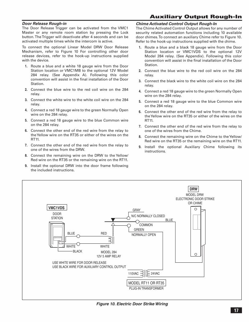
Figure 10. Electric Door Strike Wiring
Chime Activated Control Output Rough-InThe Chime Activated Control Output allows for any number of security related automation functions including 10 available door chimes. To connect an auxiliary Chime refer to Figure 10. Refer to the hook-up instructions supplied with the chime.
1. Route a blue and a black 18 gauge wire from the Door Station location or VMC1VDS to the optional 12V Model 284 relay. (See Appendix). Following this color convention will assist in the fi nal installation of the Door Station.
2. Connect the blue wire to the red coil wire on the 284 relay.
3. Connect the black wire to the white coil wire on the 284 relay.
4. Connect a red 18 gauge wire to the green Normally Open wire on the 284 relay.
5. Connect a red 18 gauge wire to the blue Common wire on the 284 relay.
6. Connect the other end of the red wire from the relay to the Yellow wire on the RT35 or either of the wires on the RT11.
7. Connect the other end of the red wire from the relay to one of the wires from the Chime.
8. Connect the remaining wire on the Chime to the Yellow/Red wire on the RT35 or the remaining wire on the RT11.
9. Install the optional Auxiliary Chime following its instructions.
Door Release Rough-inThe Door Release Trigger can be activated from the VMC1 Master or any remote room station by pressing the Lock button. The Trigger will deactivate after 4 seconds and can be activated multiple times while the intercom is active.
To connect the optional Linear Model DRW Door Release Mechanism, refer to Figure 10 For controlling other door release devices, refer to the hook-up instructions supplied with the device.
1. Route a blue and a white 18 gauge wire from the Door Station location or VMC1MB to the optional 12V Model 284 relay. (See Appendix A). Following this color convention will assist in the fi nal installation of the Door Station.
2. Connect the blue wire to the red coil wire on the 284 relay.
3. Connect the white wire to the white coil wire on the 284 relay.
4. Connect a red 18 gauge wire to the green Normally Open wire on the 284 relay.
5. Connect a red 18 gauge wire to the blue Common wire on the 284 relay.
6. Connect the other end of the red wire from the relay to the Yellow wire on the RT35 or either of the wires on the RT11.
7. Connect the other end of the red wire from the relay to one of the wires from the DRW.
8. Connect the remaining wire on the DRW to the Yellow/Red wire on the RT35 or the remaining wire on the RT11.
9. Install the optional DRW into the door frame following the included instructions.
GRAY
N/C NORMALLY CLOSED
COMMONGREEN
NORMALLY OPEN
MODEL DRW ELECTRONIC DOOR STRIKE
OR CHIME
BLUE
24VAC110VAC
MODEL RT11 OR RT35PLUG-IN TRANSFORMER
DOORSTATION
MODEL 28412V 5 AMP RELAY
BLUE
WHITE
RED
WHITEBLACK
USE WHITE WIRE FOR DOOR RELEASEUSE BLACK WIRE FOR AUXILIARY CONTROL OUTPUT
VMC1VDS
DRW
18
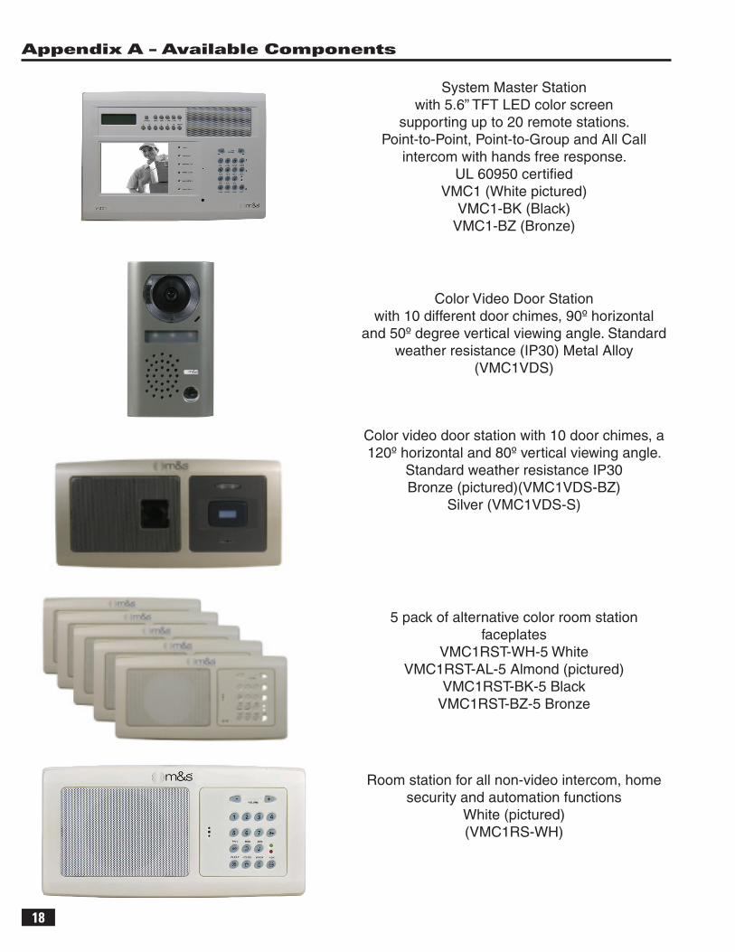
Appendix A – Available Components
System Master Station with 5.6” TFT LED color screen
supporting up to 20 remote stations. Point-to-Point, Point-to-Group and All Call
intercom with hands free response. UL 60950 certifi ed
VMC1 (White pictured)VMC1-BK (Black)
VMC1-BZ (Bronze)
Color Video Door Station with 10 different door chimes, 90º horizontal
and 50º degree vertical viewing angle. Standard weather resistance (IP30) Metal Alloy
(VMC1VDS)
Color video door station with 10 door chimes, a 120º horizontal and 80º vertical viewing angle.
Standard weather resistance IP30Bronze (pictured)(VMC1VDS-BZ)
Silver (VMC1VDS-S)
Room station for all non-video intercom, home security and automation functions
White (pictured) (VMC1RS-WH)
5 pack of alternative color room station faceplates
VMC1RST-WH-5 WhiteVMC1RST-AL-5 Almond (pictured)
VMC1RST-BK-5 BlackVMC1RST-BZ-5 Bronze
19
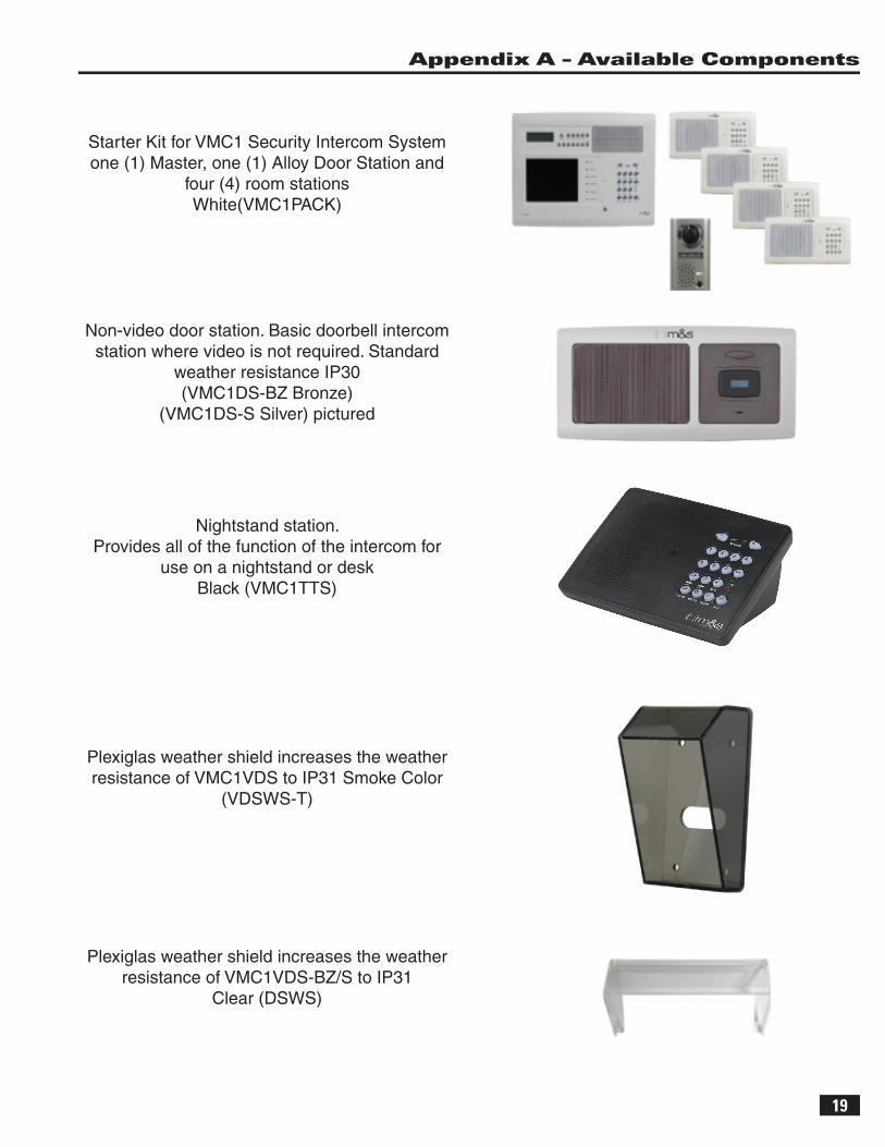
Plexiglas weather shield increases the weather resistance of VMC1VDS to IP31 Smoke Color
(VDSWS-T)
Appendix A – Available Components
Plexiglas weather shield increases the weather resistance of VMC1VDS-BZ/S to IP31
Clear (DSWS)
Nightstand station. Provides all of the function of the intercom for
use on a nightstand or desk Black (VMC1TTS)
Non-video door station. Basic doorbell intercom station where video is not required. Standard
weather resistance IP30(VMC1DS-BZ Bronze)
(VMC1DS-S Silver) pictured
Starter Kit for VMC1 Security Intercom System one (1) Master, one (1) Alloy Door Station and
four (4) room stationsWhite(VMC1PACK)
20
Appendix A – Available Components
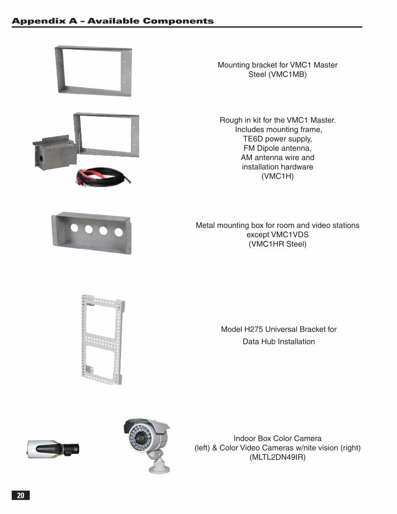
Model H275 Universal Bracket for
Data Hub Installation
Indoor Box Color Camera(left) & Color Video Cameras w/nite vision (right)
(MLTL2DN49IR)
Rough in kit for the VMC1 Master. Includes mounting frame,
TE6D power supply, FM Dipole antenna,
AM antenna wire and installation hardware
(VMC1H)
Metal mounting box for room and video stations except VMC1VDS(VMC1HR Steel)
Mounting bracket for VMC1 MasterSteel (VMC1MB)
21
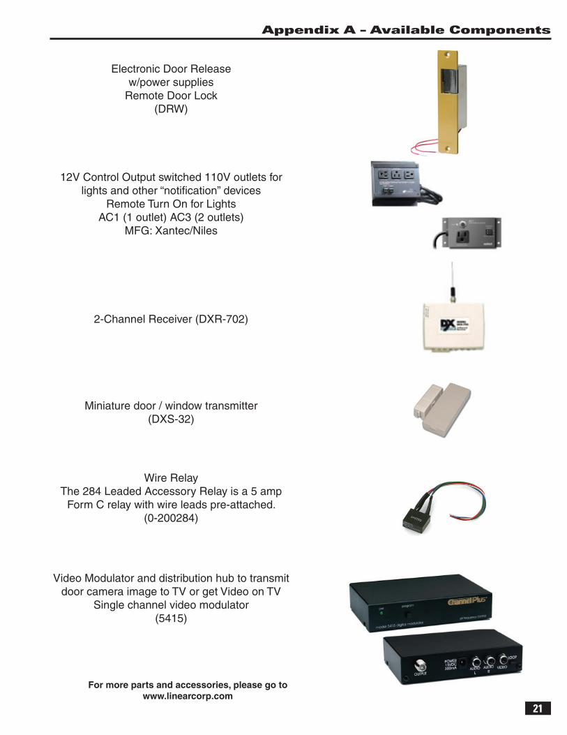
Miniature door / window transmitter(DXS-32)
2-Channel Receiver (DXR-702)
12V Control Output switched 110V outlets for lights and other “notifi cation” devices
Remote Turn On for Lights AC1 (1 outlet) AC3 (2 outlets)
MFG: Xantec/Niles
Wire RelayThe 284 Leaded Accessory Relay is a 5 amp
Form C relay with wire leads pre-attached. (0-200284)
Video Modulator and distribution hub to transmit door camera image to TV or get Video on TV
Single channel video modulator(5415)
Electronic Door Release w/power supplies
Remote Door Lock(DRW)
For more parts and accessories, please go to www.linearcorp.com
Appendix A – Available Components
2 - Year Limited Warranty
Linear LLC warrants these products to be free of defects for 2 years. The warranty period begins on either (a) the date of purchase or installation date of this product or (b) the date of closing on a new residence in which this product was originally installed. The warranty extends to the original user of the product and to each subsequent owner of the product during the term of the warranty. Linear LLC will repair or replace, at its option, parts and materials at no charge. Parts supplied under this warranty may be new or rebuilt at the option of Linear LLC.
If during the warranty period the product appears to have a defect, please call our toll free service number (800-421-1587) prior to dismantling. Dismantling the product prior to calling our service number may void the warranty. Before returning any product to Linear LLC, contact your local dealer or distributor. Linear LLC will return the repaired product freight prepaid within the continental United States. There are no obligations or liabilities on the part of Linear LLC for consequential damages arising out of or in connection with use or performance of this product or other indirect damages with respect to loss of property, revenue, or profi t, or cost of removal, installation, or reinstallation.
ANY PRODUCT RETURNED TO LINEAR LLC WITHOUT A RPA NUMBER WILL BE REFUSED. This limited warranty is in lieu of any other warranties, express or implied, including any implied warranty of merchantability or fi tness for a particular purpose or otherwise, and of any other obligations or liability on the seller’s part. This limited warranty does not cover damage caused by improper installation, acts of God, criminal acts, the violation of applicable building or electrical codes or the use of non-recommended wire, cable (excluding Cat-5 and RG-6) or wall housings.Under no circumstances shall Linear LLC be liable for consequential, incidental or special damages arising in connection with use, or inability to use this product. In no event shall Linear LLC liability hereunder exceed the cost of the product covered hereby. No person is authorized to assume for us or obligate us for any other liability in connection with the sale of this product. Some states do not allow the exclusion or limitation of consequential, incidental or special damages, so the above limitation or exclusion may not apply to you. This limited warranty gives you specifi c legal rights, and you may also have other rights, which vary from state to state. This Linear LLC Warranty is in lieu of all other warranties express or implied.
Copyright © 2012 Linear LLC 233254 AX3
USA & Canada (800) 421-1587 & (800) 392-0123(760) 438-7000 - Toll Free FAX (800) 468-1340
www.linearcorp.com


![ISSN 0280-316X10520/...cavity quantum electrodynamics, or shortly cavity QED [2]. As with any physical As with any physical model, the degrees of freedom that are not important for](https://img.pdfslide.net/doc/110x75/5f76355d4bc22f497a18e973/issn-0280-316x-10520-cavity-quantum-electrodynamics-or-shortly-cavity-qed-2.jpg)