Embed Size (px)
Citation preview
ibm.com/redbooks Redpaper
Front cover
VMware Implementationwith IBM System Storage DS5000
Sangam RacherlaMario David Ganem
Hrvoje Stanilovic
Introduction to VMware
VMware and Storage Planning
VMware and Storage Configuration

International Technical Support Organization
VMware Implementation with IBM System Storage DS5000
November 2012
REDP-4609-01
© Copyright International Business Machines Corporation 2012. All rights reserved.Note to U.S. Government Users Restricted Rights -- Use, duplication or disclosure restricted by GSA ADP ScheduleContract with IBM Corp.
Second Edition (November 2012)
This edition applies to:VMware vSphere ESXi 5IBM Midrange Storage DS5000 running V7.77 firmwareIBM System Storage DS Storage Manager V10.77.
This document created or updated on November 16, 2012.
Note: Before using this information and the product it supports, read the information in “Notices” on page vii.
Contents
Notices . . . . . . . . . . . . . . . . . . . . . . . . . . . . . . . . . . . . . . . . . . . . . . . . . . . . . . . . . . . . . . . . . viiTrademarks . . . . . . . . . . . . . . . . . . . . . . . . . . . . . . . . . . . . . . . . . . . . . . . . . . . . . . . . . . . . . viii
Preface . . . . . . . . . . . . . . . . . . . . . . . . . . . . . . . . . . . . . . . . . . . . . . . . . . . . . . . . . . . . . . . . . ixThe team who wrote this paper . . . . . . . . . . . . . . . . . . . . . . . . . . . . . . . . . . . . . . . . . . . . . . . ixNow you can become a published author, too! . . . . . . . . . . . . . . . . . . . . . . . . . . . . . . . . . . . .xComments welcome. . . . . . . . . . . . . . . . . . . . . . . . . . . . . . . . . . . . . . . . . . . . . . . . . . . . . . . . .xStay connected to IBM Redbooks . . . . . . . . . . . . . . . . . . . . . . . . . . . . . . . . . . . . . . . . . . . . . xi
Part 1. Planning. . . . . . . . . . . . . . . . . . . . . . . . . . . . . . . . . . . . . . . . . . . . . . . . . . . . . . . . . . . . . . . . . . . . . . . 1
Chapter 1. Introduction of IBM VMware Midrange Storage Solutions . . . . . . . . . . . . . . 31.1 Overview of IBM VMware Midrange Storage Solutions . . . . . . . . . . . . . . . . . . . . . . . . . 41.2 IBM VMware Storage Solutions . . . . . . . . . . . . . . . . . . . . . . . . . . . . . . . . . . . . . . . . . . . 5
1.2.1 VMware vSphere ESXi architecture . . . . . . . . . . . . . . . . . . . . . . . . . . . . . . . . . . . . 61.2.2 Overview of using VMware vSphere with SAN . . . . . . . . . . . . . . . . . . . . . . . . . . . . 71.2.3 Benefits of using VMware vSphere with SAN . . . . . . . . . . . . . . . . . . . . . . . . . . . . . 81.2.4 VMware vSphere and SAN use cases . . . . . . . . . . . . . . . . . . . . . . . . . . . . . . . . . . 8
1.3 Overview of VMware vStorage APIs for Data Protection . . . . . . . . . . . . . . . . . . . . . . . . 91.4 Overview of VMware vCenter Site Recovery Manager . . . . . . . . . . . . . . . . . . . . . . . . . 10
Chapter 2. Security Design of the VMware vSphere Infrastructure Architecture . . . . 132.1 Introduction . . . . . . . . . . . . . . . . . . . . . . . . . . . . . . . . . . . . . . . . . . . . . . . . . . . . . . . . . . 142.2 Virtualization Layer . . . . . . . . . . . . . . . . . . . . . . . . . . . . . . . . . . . . . . . . . . . . . . . . . . . . 15
2.2.1 Local Support Consoles . . . . . . . . . . . . . . . . . . . . . . . . . . . . . . . . . . . . . . . . . . . . 162.3 CPU Virtualization . . . . . . . . . . . . . . . . . . . . . . . . . . . . . . . . . . . . . . . . . . . . . . . . . . . . . 172.4 Memory Virtualization . . . . . . . . . . . . . . . . . . . . . . . . . . . . . . . . . . . . . . . . . . . . . . . . . . 182.5 Virtual Machines . . . . . . . . . . . . . . . . . . . . . . . . . . . . . . . . . . . . . . . . . . . . . . . . . . . . . . 192.6 Virtual Networking Layer . . . . . . . . . . . . . . . . . . . . . . . . . . . . . . . . . . . . . . . . . . . . . . . . 20
2.6.1 Virtual Standard Switches. . . . . . . . . . . . . . . . . . . . . . . . . . . . . . . . . . . . . . . . . . . 212.6.2 Virtual Distributed Switches . . . . . . . . . . . . . . . . . . . . . . . . . . . . . . . . . . . . . . . . . 212.6.3 Virtual Switch VLANs . . . . . . . . . . . . . . . . . . . . . . . . . . . . . . . . . . . . . . . . . . . . . . 222.6.4 Virtual Ports . . . . . . . . . . . . . . . . . . . . . . . . . . . . . . . . . . . . . . . . . . . . . . . . . . . . . 232.6.5 Virtual Network Adapters . . . . . . . . . . . . . . . . . . . . . . . . . . . . . . . . . . . . . . . . . . . 242.6.6 Virtual Switch Isolation . . . . . . . . . . . . . . . . . . . . . . . . . . . . . . . . . . . . . . . . . . . . . 242.6.7 Virtual Switch Correctness . . . . . . . . . . . . . . . . . . . . . . . . . . . . . . . . . . . . . . . . . . 25
2.7 Virtualized Storage . . . . . . . . . . . . . . . . . . . . . . . . . . . . . . . . . . . . . . . . . . . . . . . . . . . . 262.8 SAN security . . . . . . . . . . . . . . . . . . . . . . . . . . . . . . . . . . . . . . . . . . . . . . . . . . . . . . . . . 262.9 VMware vSphere vCenter Server . . . . . . . . . . . . . . . . . . . . . . . . . . . . . . . . . . . . . . . . . 27
Chapter 3. Planning the VMware vSphere Storage System Design . . . . . . . . . . . . . . . 293.1 VMware vSphere ESXi Server Storage structure: Disk virtualization . . . . . . . . . . . . . . 30
3.1.1 Local Storage . . . . . . . . . . . . . . . . . . . . . . . . . . . . . . . . . . . . . . . . . . . . . . . . . . . . 303.1.2 Networked Storage . . . . . . . . . . . . . . . . . . . . . . . . . . . . . . . . . . . . . . . . . . . . . . . . 303.1.3 SAN disk usage . . . . . . . . . . . . . . . . . . . . . . . . . . . . . . . . . . . . . . . . . . . . . . . . . . 323.1.4 Disk virtualization with VMFS volumes and .vmdk files . . . . . . . . . . . . . . . . . . . . . 333.1.5 VMFS access mode: Public mode . . . . . . . . . . . . . . . . . . . . . . . . . . . . . . . . . . . . 343.1.6 vSphere Server .vmdk modes . . . . . . . . . . . . . . . . . . . . . . . . . . . . . . . . . . . . . . . . 343.1.7 Specifics of using SAN Arrays with vSphere ESXi Server . . . . . . . . . . . . . . . . . . 34
© Copyright IBM Corp. 2012. All rights reserved. iii
3.1.8 Host types . . . . . . . . . . . . . . . . . . . . . . . . . . . . . . . . . . . . . . . . . . . . . . . . . . . . . . . 353.1.9 Levels of indirection . . . . . . . . . . . . . . . . . . . . . . . . . . . . . . . . . . . . . . . . . . . . . . . 36
3.2 Deciding which IBM Midrange Storage Subsystem to use . . . . . . . . . . . . . . . . . . . . . . 363.3 Overview of IBM Midrange Storage Systems . . . . . . . . . . . . . . . . . . . . . . . . . . . . . . . . 37
3.3.1 Positioning the IBM Midrange Storage Systems. . . . . . . . . . . . . . . . . . . . . . . . . . 373.4 Storage Subsystem considerations. . . . . . . . . . . . . . . . . . . . . . . . . . . . . . . . . . . . . . . . 38
3.4.1 Segment size . . . . . . . . . . . . . . . . . . . . . . . . . . . . . . . . . . . . . . . . . . . . . . . . . . . . 383.4.2 DS5000 cache features . . . . . . . . . . . . . . . . . . . . . . . . . . . . . . . . . . . . . . . . . . . . 403.4.3 Enabling cache settings . . . . . . . . . . . . . . . . . . . . . . . . . . . . . . . . . . . . . . . . . . . . 413.4.4 Aligning file system partitions . . . . . . . . . . . . . . . . . . . . . . . . . . . . . . . . . . . . . . . . 413.4.5 Premium features . . . . . . . . . . . . . . . . . . . . . . . . . . . . . . . . . . . . . . . . . . . . . . . . . 413.4.6 Considering individual virtual machines . . . . . . . . . . . . . . . . . . . . . . . . . . . . . . . . 413.4.7 Determining the best RAID level for logical drives and arrays . . . . . . . . . . . . . . . 423.4.8 Server consolidation considerations . . . . . . . . . . . . . . . . . . . . . . . . . . . . . . . . . . . 443.4.9 VMware ESXi Server Storage configurations . . . . . . . . . . . . . . . . . . . . . . . . . . . . 463.4.10 Configurations by function . . . . . . . . . . . . . . . . . . . . . . . . . . . . . . . . . . . . . . . . . 493.4.11 Zoning . . . . . . . . . . . . . . . . . . . . . . . . . . . . . . . . . . . . . . . . . . . . . . . . . . . . . . . . . 52
Chapter 4. Planning the VMware vSphere Server Design . . . . . . . . . . . . . . . . . . . . . . . 554.1 Considering the VMware vSphere Server platform. . . . . . . . . . . . . . . . . . . . . . . . . . . . 56
4.1.1 Minimum server requirements. . . . . . . . . . . . . . . . . . . . . . . . . . . . . . . . . . . . . . . . 564.1.2 Maximum physical machine specifications . . . . . . . . . . . . . . . . . . . . . . . . . . . . . . 564.1.3 Recommendations for enhanced performance. . . . . . . . . . . . . . . . . . . . . . . . . . . 574.1.4 Considering the server hardware architecture . . . . . . . . . . . . . . . . . . . . . . . . . . . 574.1.5 General performance and sizing considerations. . . . . . . . . . . . . . . . . . . . . . . . . . 61
4.2 Operating system considerations . . . . . . . . . . . . . . . . . . . . . . . . . . . . . . . . . . . . . . . . . 624.2.1 Buffering the I/O . . . . . . . . . . . . . . . . . . . . . . . . . . . . . . . . . . . . . . . . . . . . . . . . . . 624.2.2 Aligning host I/O with RAID striping . . . . . . . . . . . . . . . . . . . . . . . . . . . . . . . . . . . 634.2.3 Recommendations for host bus adapter settings . . . . . . . . . . . . . . . . . . . . . . . . . 634.2.4 Recommendations for Fibre Channel Switch settings . . . . . . . . . . . . . . . . . . . . . 634.2.5 Using Command Tag Queuing . . . . . . . . . . . . . . . . . . . . . . . . . . . . . . . . . . . . . . . 644.2.6 Analyzing I/O characteristics. . . . . . . . . . . . . . . . . . . . . . . . . . . . . . . . . . . . . . . . . 644.2.7 Using VFMS for spanning across multiple LUNs . . . . . . . . . . . . . . . . . . . . . . . . . 65
Part 2. Configuration . . . . . . . . . . . . . . . . . . . . . . . . . . . . . . . . . . . . . . . . . . . . . . . . . . . . . . . . . . . . . . . . . 67
Chapter 5. VMware ESXi Server and Storage Configuration . . . . . . . . . . . . . . . . . . . . 695.1 Storage configuration . . . . . . . . . . . . . . . . . . . . . . . . . . . . . . . . . . . . . . . . . . . . . . . . . . 70
5.1.1 Notes about mapping LUNs to a storage partition . . . . . . . . . . . . . . . . . . . . . . . . 725.1.2 Steps for verifying the storage configuration for VMware . . . . . . . . . . . . . . . . . . . 72
5.2 Installing the VMware ESXi Server . . . . . . . . . . . . . . . . . . . . . . . . . . . . . . . . . . . . . . . . 745.2.1 Prerequisites . . . . . . . . . . . . . . . . . . . . . . . . . . . . . . . . . . . . . . . . . . . . . . . . . . . . . 745.2.2 Configuring the hardware . . . . . . . . . . . . . . . . . . . . . . . . . . . . . . . . . . . . . . . . . . . 755.2.3 Configuring the software on the VMware ESXi Server host . . . . . . . . . . . . . . . . . 795.2.4 Connecting to the VMware ESXi Server . . . . . . . . . . . . . . . . . . . . . . . . . . . . . . . . 845.2.5 Creating virtual switches for guest connectivity . . . . . . . . . . . . . . . . . . . . . . . . . . 905.2.6 Connecting to SAN storage by using iSCSI . . . . . . . . . . . . . . . . . . . . . . . . . . . . . 945.2.7 Configuring VMware ESXi Server Storage . . . . . . . . . . . . . . . . . . . . . . . . . . . . . 1195.2.8 Verifying the multipathing policy for Fibre Channel LUNs. . . . . . . . . . . . . . . . . . 1265.2.9 Creating virtual machines . . . . . . . . . . . . . . . . . . . . . . . . . . . . . . . . . . . . . . . . . . 1285.2.10 Additional VMware ESXi Server Storage configuration . . . . . . . . . . . . . . . . . . 141
Chapter 6. VMware Command Line Tools for Configuring vSphere ESXi Storage . . 1456.1 Introduction to Command-line tools . . . . . . . . . . . . . . . . . . . . . . . . . . . . . . . . . . . . . . 146
iv VMware Implementation with IBM System Storage DS5000
6.1.1 Enabling ESXi Shell . . . . . . . . . . . . . . . . . . . . . . . . . . . . . . . . . . . . . . . . . . . . . . 1466.1.2 Running ESXi Shell Commands . . . . . . . . . . . . . . . . . . . . . . . . . . . . . . . . . . . . . 1476.1.3 Saving time by running ESXi Shell commands. . . . . . . . . . . . . . . . . . . . . . . . . . 147
6.2 Connecting to SAN storage by using iSCSI . . . . . . . . . . . . . . . . . . . . . . . . . . . . . . . . 1486.2.1 Activate the Software iSCSI Adapter . . . . . . . . . . . . . . . . . . . . . . . . . . . . . . . . . 1486.2.2 Configure networking for iSCSI. . . . . . . . . . . . . . . . . . . . . . . . . . . . . . . . . . . . . . 1496.2.3 Configure iSCSI discovery addresses. . . . . . . . . . . . . . . . . . . . . . . . . . . . . . . . . 1516.2.4 Enabling security. . . . . . . . . . . . . . . . . . . . . . . . . . . . . . . . . . . . . . . . . . . . . . . . . 152
6.3 Connecting to SAN storage by using Fibre Channel. . . . . . . . . . . . . . . . . . . . . . . . . . 1526.4 Matching DS logical drives with VMware vSphere ESXi devices . . . . . . . . . . . . . . . . 156
Appendix A. VMware ESXi Fibre Channel Configuration Checklist . . . . . . . . . . . . . . 159Hardware, cabling, and zoning best practices . . . . . . . . . . . . . . . . . . . . . . . . . . . . . . . . . . 160DS5000 Settings . . . . . . . . . . . . . . . . . . . . . . . . . . . . . . . . . . . . . . . . . . . . . . . . . . . . . . . . 161VMware ESXi Server Settings . . . . . . . . . . . . . . . . . . . . . . . . . . . . . . . . . . . . . . . . . . . . . . 162Restrictions . . . . . . . . . . . . . . . . . . . . . . . . . . . . . . . . . . . . . . . . . . . . . . . . . . . . . . . . . . . . 163
Related publications . . . . . . . . . . . . . . . . . . . . . . . . . . . . . . . . . . . . . . . . . . . . . . . . . . . . 165IBM Redbooks . . . . . . . . . . . . . . . . . . . . . . . . . . . . . . . . . . . . . . . . . . . . . . . . . . . . . . . . . . 165Other resources . . . . . . . . . . . . . . . . . . . . . . . . . . . . . . . . . . . . . . . . . . . . . . . . . . . . . . . . . 165Referenced Web sites . . . . . . . . . . . . . . . . . . . . . . . . . . . . . . . . . . . . . . . . . . . . . . . . . . . . 165How to get IBM Redbooks publications . . . . . . . . . . . . . . . . . . . . . . . . . . . . . . . . . . . . . . . 165Help from IBM . . . . . . . . . . . . . . . . . . . . . . . . . . . . . . . . . . . . . . . . . . . . . . . . . . . . . . . . . . 166
Contents v

vi VMware Implementation with IBM System Storage DS5000
Notices
This information was developed for products and services offered in the U.S.A.
IBM may not offer the products, services, or features discussed in this document in other countries. Consult your local IBM representative for information on the products and services currently available in your area. Any reference to an IBM product, program, or service is not intended to state or imply that only that IBM product, program, or service may be used. Any functionally equivalent product, program, or service that does not infringe any IBM intellectual property right may be used instead. However, it is the user's responsibility to evaluate and verify the operation of any non-IBM product, program, or service.
IBM may have patents or pending patent applications covering subject matter described in this document. The furnishing of this document does not give you any license to these patents. You can send license inquiries, in writing, to: IBM Director of Licensing, IBM Corporation, North Castle Drive, Armonk, NY 10504-1785 U.S.A.
The following paragraph does not apply to the United Kingdom or any other country where such provisions are inconsistent with local law: INTERNATIONAL BUSINESS MACHINES CORPORATION PROVIDES THIS PUBLICATION "AS IS" WITHOUT WARRANTY OF ANY KIND, EITHER EXPRESS OR IMPLIED, INCLUDING, BUT NOT LIMITED TO, THE IMPLIED WARRANTIES OF NON-INFRINGEMENT, MERCHANTABILITY OR FITNESS FOR A PARTICULAR PURPOSE. Some states do not allow disclaimer of express or implied warranties in certain transactions, therefore, this statement may not apply to you.
This information could include technical inaccuracies or typographical errors. Changes are periodically made to the information herein; these changes will be incorporated in new editions of the publication. IBM may make improvements and/or changes in the product(s) and/or the program(s) described in this publication at any time without notice.
Any references in this information to non-IBM websites are provided for convenience only and do not in any manner serve as an endorsement of those websites. The materials at those websites are not part of the materials for this IBM product and use of those websites is at your own risk.
IBM may use or distribute any of the information you supply in any way it believes appropriate without incurring any obligation to you.
Information concerning non-IBM products was obtained from the suppliers of those products, their published announcements or other publicly available sources. IBM has not tested those products and cannot confirm the accuracy of performance, compatibility or any other claims related to non-IBM products. Questions on the capabilities of non-IBM products should be addressed to the suppliers of those products.
This information contains examples of data and reports used in daily business operations. To illustrate them as completely as possible, the examples include the names of individuals, companies, brands, and products. All of these names are fictitious and any similarity to the names and addresses used by an actual business enterprise is entirely coincidental.
COPYRIGHT LICENSE:
This information contains sample application programs in source language, which illustrate programming techniques on various operating platforms. You may copy, modify, and distribute these sample programs in any form without payment to IBM, for the purposes of developing, using, marketing or distributing application programs conforming to the application programming interface for the operating platform for which the sample programs are written. These examples have not been thoroughly tested under all conditions. IBM, therefore, cannot guarantee or imply reliability, serviceability, or function of these programs.
© Copyright IBM Corp. 2012. All rights reserved. vii
Trademarks
IBM, the IBM logo, and ibm.com are trademarks or registered trademarks of International Business Machines Corporation in the United States, other countries, or both. These and other IBM trademarked terms are marked on their first occurrence in this information with the appropriate symbol (® or ™), indicating US registered or common law trademarks owned by IBM at the time this information was published. Such trademarks may also be registered or common law trademarks in other countries. A current list of IBM trademarks is available on the Web at http://www.ibm.com/legal/copytrade.shtml
The following terms are trademarks of the International Business Machines Corporation in the United States, other countries, or both:
AIX®DB2®DS4000®DS8000®FlashCopy®
IBM®Redbooks®Redpaper™Redbooks (logo) ®System p®
System Storage DS®System Storage®System x®Tivoli®
The following terms are trademarks of other companies:
Intel, Intel logo, Intel Inside logo, and Intel Centrino logo are trademarks or registered trademarks of Intel Corporation or its subsidiaries in the United States and other countries.
Linux is a trademark of Linus Torvalds in the United States, other countries, or both.
Microsoft, Windows, and the Windows logo are trademarks of Microsoft Corporation in the United States, other countries, or both.
Java, and all Java-based trademarks and logos are trademarks or registered trademarks of Oracle and/or its affiliates.
Snapshot, and the NetApp logo are trademarks or registered trademarks of NetApp, Inc. in the U.S. and other countries.
Intel, Intel logo, Intel Inside, Intel Inside logo, Intel Centrino, Intel Centrino logo, Celeron, Intel Xeon, Intel SpeedStep, Itanium, and Pentium are trademarks or registered trademarks of Intel Corporation or its subsidiaries in the United States and other countries.
Other company, product, or service names may be trademarks or service marks of others.
viii VMware Implementation with IBM System Storage DS5000
Preface
In this IBM® Redpaper™, we compiled best practices for planning, designing, implementing, and maintaining IBM Midrange storage solutions. We also compiled configurations for a VMware ESX and VMware ESXi Server-based host environment.
Setting up an IBM Midrange Storage Subsystem is a challenging task and our principal objective in this book is to provide you with a sufficient overview to effectively enable storage area network (SAN) storage and VMWare. There is no single configuration that is satisfactory for every application or situation. However, the effectiveness of VMware implementation is enabled by careful planning and consideration. Although the compilation of this publication is derived from an actual setup and verification, we did not stress test or test for all possible use cases that are used in a limited configuration assessment.
Because of the highly customizable nature of a VMware ESXi host environment, you must consider your specific environment and equipment to achieve optimal performance from an IBM Midrange Storage Subsystem. When you are weighing the recommendations in this publication, you must start with the first principles of input/output (I/O) performance tuning. Remember that each environment is unique and the correct settings that are used depend on the specific goals, configurations, and demands for the specific environment.
This Redpaper is intended for technical professionals who want to deploy VMware ESXi and VMware ESX Servers with IBM Midrange Storage Subsystems.
The team who wrote this paper
This paper was produced by a team of specialists from around the world working at the International Technical Support Organization, Poughkeepsie Center.
Sangam Racherla is an IT Specialist and Project Leader working at the ITSO in San Jose, CA. He has 12 years of experience in the IT field, the last eight years with ITSO. Sangam has extensive experience in installing and supporting the ITSO lab equipment for various IBM Redbook® projects. He has expertise in working with Microsoft Windows, Linux, IBM AIX®, System x®, and System p® servers, and various SAN and storage products. Sangam holds a degree in electronics and communication engineering.
Mario David Ganem is an IT professional, specialized in cloud computing and storage solutions. He has 15 years of experience in the IT industry. Mario works as Infrastructure IT Architect in the Delivery Center in Argentina. Before starting his career at IBM in 2006, Mario worked in many companies such as Hewlett Packard, Compaq, and Unisys. He developed the internal virtualization products curricula training that he teaches to DCA professionals. He holds many industry certifications from various companies, including Microsoft, RedHat, VMWare, Novell, Cisco, CompTIA, HP, and Compaq.
Hrvoje Stanilovic is an IBM Certified Specialist - Midrange Storage Technical Support and Remote Support Engineer working for IBM Croatia. He is a member of CEEMEA VFE Midrange Storage Support team and EMEA PFE Support team, and provides Level 2 support for DS3000, DS4000®, and DS5000 products in Europe, Middle East, and Africa. His primary focus is post-sales Midrange Storage, SAN, and Storage Virtualization support. He also supports local projects, mentoring, and knowledge sharing. Over the past four years at IBM,
© Copyright IBM Corp. 2012. All rights reserved. ix
he transitioned through various roles, including IBM System p hardware support and Cisco networking support, before he worked with Midrange Storage systems.
The authors want to express their thanks to the following people, whose expertise and support were integral to the writing of this IBM Redpaper:
� Harold Pike� Pete Urbisci� Bill Wilson� Alex Osuna� Jon Tate� Bertrand Dufrasne� Karen Orlando� Larry Coyne� Ann Lund� Georgia L Mann
� IBM
Brian StefflerYong Choi
� Brocade Communication Systems, Inc.
Now you can become a published author, too!
Here’s an opportunity to spotlight your skills, grow your career, and become a published author—all at the same time! Join an ITSO residency project and help write a book in your area of expertise, while honing your experience by using leading-edge technologies. Your efforts will help to increase product acceptance and customer satisfaction, as you expand your network of technical contacts and relationships. Residencies run from two to six weeks in length, and you can participate either in person or as a remote resident working from your home base.
Find out more about the residency program, browse the residency index, and apply online at:
http://www.ibm.com/redbooks/residencies.html
Comments welcome
Your comments are important to us!
We want our papers to be as helpful as possible. Send us your comments about this paper or other IBM Redbooks publications in one of the following ways:
� Use the online Contact us review Redbooks form found at:
http://www.ibm.com/redbooks
� Send your comments in an email to:
� Mail your comments to:
IBM Corporation, International Technical Support OrganizationDept. HYTD Mail Station P099
x VMware Implementation with IBM System Storage DS5000
2455 South RoadPoughkeepsie, NY 12601-5400
Stay connected to IBM Redbooks
� Find us on Facebook:
http://www.facebook.com/IBMRedbooks
� Follow us on Twitter:
http://twitter.com/ibmredbooks
� Look for us on LinkedIn:
http://www.linkedin.com/groups?home=&gid=2130806
� Explore new Redbooks publications, residencies, and workshops with the IBM Redbooks weekly newsletter:
https://www.redbooks.ibm.com/Redbooks.nsf/subscribe?OpenForm
� Stay current on recent Redbooks publications with RSS Feeds:
http://www.redbooks.ibm.com/rss.html
Preface xi

xii VMware Implementation with IBM System Storage DS5000
Part 1 Planning
In part 1, we provide the conceptual framework for understanding IBM Midrange Storage Systems in a Storage Area Network (SAN) and vSphere environment. We include recommendations, hints, and tips for the physical installation, cabling, and zoning. Although performance figures are not included, we discuss the performance and tuning of various components and features to guide you when you are working with IBM Midrange Storage.
Before you start any configuration of the IBM Midrange Storage Subsystem in a VMware vSphere environment, you must understand the following concepts to guide you in your planning:
� Recognizing the IBM Midrange Storage Subsystem feature set� Balancing drive-side performance� Understanding the segment size of logical drives� Knowing about storage system cache improvements� Comprehending file system alignment � Knowing how to allocate logical drives for vSphere ESXi hosts� Recognizing server hardware architecture� Identifying specific vSphere ESXi settings
Assistance in planning for the optimal design of your implementation is provided in the next chapters.
Part 1
© Copyright IBM Corp. 2012. All rights reserved. 1

2 VMware Implementation with IBM System Storage DS5000
Chapter 1. Introduction of IBM VMware Midrange Storage Solutions
In this chapter, we introduce you to the IBM VMware Midrange Storage Solutions and provide an overview of the components that are involved.
1
Important: This IBM Redpaper refers to the supported versions with the following terminology:
� ESX server: Refers to VMware ESX or VMware ESXi servers in VMware vSphere Version 4.0, 4.1, 5.0
� vCenter Server: Refers to VMware Virtual Center Version 2.5 or VMware vCenter servers in VMware vSphere Version 4.0, 4.1, and 5.0
© Copyright IBM Corp. 2012. All rights reserved. 3
1.1 Overview of IBM VMware Midrange Storage Solutions
Many enterprises implemented VMware or plan to implement VMware. VMware provides more efficient use of assets and lower costs by consolidating servers and storage. Applications that ran in under-used dedicated physical servers are migrated to their own virtual machine or virtual server that is part of a VMware ESX cluster or a virtual infrastructure.
As part of this consolidation, asset usage often is increased from less than 10% to over 85%. Applications that included dedicated internal storage now use a shared networked storage system that pools storage to all of the virtual machines and their applications. Back up, restore, and disaster recovery becomes more effective and easier to manage. Because of the consolidated applications and their mixed-workloads, the storage system must deliver balanced performance and high performance to support existing IT service-level agreements (SLA). The IBM Midrange Storage Systems provide an effective means to that end.
IBM Midrange Storage Systems are designed to deliver reliable performance for mixed applications, including transaction and sequential workloads. These workloads feature applications that are typical of a virtual infrastructure, including email, database, web server, file server, data warehouse, and backup profiles. IBM offers a complete line of storage systems from entry-level to midrange to enterprise-level systems that are certified to work with VMware vSphere ESX Server.
The IBM Midrange Storage systems that are discussed in this publication include the DS5100, DS5300, and DS5020 models. The systems are included in the references throughout the manuals as DS-Series. We discuss these storage subsystems in greater detail in Chapter 3, “Planning the VMware vSphere Storage System Design” on page 29.
These systems offer shared storage that enables the following VMware advanced functionality:
� vSphere Distributed Resource Scheduler (DRS)� vCenter Site Recovery Manager (SRM)� vSphere High Availability (HA)� vSphere Fault Tolerance (FT)� vSphere Virtual Machine File System (VMFS)� vSphere vMotion� VMware vSphere Storage vMotion
The IBM DS5000 storage systems include the following features:
� Highest performance and the most scalability, expandability, and investment protection that is available in the IBM Midrange portfolio
� Enterprise-class features and availability
� Capacity to handle the largest and most demanding virtual infrastructure workloads
� Support for up to 448 Fibre Channel, FC-SAS, or SATA drives with EXP5000 and up to 480 drives when 8 x EXP5060s are attached
� Support of VMware vCenter Site Recovery Manager 4.1(SRM)
Important: As of this writing, VMware vCenter Site Recovery Manager 4.1(SRM) is only officially supported by IBM Data Studio System Storage® DS5000. Official SRM5 support is anticipated.
4 VMware Implementation with IBM System Storage DS5000
1.2 IBM VMware Storage Solutions
Many companies consider and employ VMware virtualization solutions to reduce IT costs and increase the efficiency, usage, and flexibility of their hardware. Over 100,000 customers deployed VMware, including 90% of Fortune 1000 businesses. Yet, maximizing the operational benefits from virtualization requires network storage that helps optimize the VMware infrastructure.
The IBM Storage solutions for VMware offer customers the following benefits:
� Flexibility: Support for iSCSI and Fibre Channel shared storage, and HBA and storage port multi-pathing and boot from SAN.
� Performance: Outstanding high-performance, block-level storage that scales with VMware’s VMFS file system, independently verified high performance by the SPC-1 and SPC-2 (Storage Performance Council) benchmarks, and balanced performance that is delivered by the IBM Midrange Storage Systems for mixed applications that run in a virtual infrastructure.
� Horizontal scalability: From entry-level through midrange to enterprise class network storage with commonality of platform and storage management.
� Hot Backup and Quick recovery: Non-disruptive backup solutions that use Tivoli® and NetBackup with and without VMware vStorage APIs for Data Protection, which provides quick recovery at the file or virtual machine level.
� Disaster recovery: DS5000 Enhanced Remote Mirror that offers affordable disaster recovery with automatic failover with VMware vCenter Site Recovery Manager 4.1(SRM).
� Affordability: Low total cost of ownership (TCO) shared storage is included with IBM Storage Manager Software and there are no separate software maintenance fees. Cost-effective tiered storage within the same storage system, leveraging Fibre Channel drives for high performance, and SATA drives for economical capacity also add to the solution’s affordability features.
� Efficiency: Data Services features, such as FlashCopy® and VolumeCopy enable VMware Centralized Backup to disk and eliminate backup windows. Also provides the required network storage for VMware ESX Server features, such as VMware vSphere vMotion, VMware vSphere Storage vMotion, VMware vSphere Distributed Resource Scheduler (DRS), and VMware vSphere High Availability (HA).
VMware vSphere includes components and features that are essential for managing virtual machines. The following components and features form part of the VMware vSphere suite:
� vSphere ESXi� vSphere vCenter Server� vSphere VMFS� vSphere Fault Tolerance (FT)� vSphere vMotion� vSphere High Availability (HA)� vSphere Distributed Resource Scheduler (DRS)� vSphere Storage vMotion (SVMotion)� vSphere Distributed Power Management (DPM)� vSphere Storage I/O control (SIOC)� vSphere Network I/O control
Chapter 1. Introduction of IBM VMware Midrange Storage Solutions 5
1.2.1 VMware vSphere ESXi architecture
VMware vSphere ESXi is virtual infrastructure partitioning software that is designed for server consolidation, rapid deployment of new servers, increased availability, and simplified management. The software improves hardware utilization and saves costs that are associated space, IT staffing, and hardware.
VMware vSphere virtualizes the entire IT infrastructure, including servers, storage, and networks. It groups these heterogeneous resources and transforms the rigid, inflexible infrastructure into a simple and unified manageable set of elements in the virtualized environment. With vSphere, IT resources are managed like a shared utility and are quickly provisioned to different business units and projects without worrying about the underlying hardware differences and limitations.
Many people might have earlier experience with VMware's virtualization products in the form of VMware Workstation or VMware Server. VMware vSphere ESXi is different from other VMware products because it runs directly on the hardware, which is considered a bare-metal solution. VMware vSphere ESXi also offers a mainframe-class virtualization software platform that enables the deployment of multiple, secure, and independent virtual machines on a single physical server.
VMware vSphere ESXi allows several instances of operating systems, such as Microsoft Windows Server, Red Hat, SuSE Linux, and MacOS to run in partitions that are independent of one another. Therefore, this technology is a key software enabler for server consolidation that moves existing, unmodified applications and operating system environments from many older systems onto a smaller number of new high-performance System x platforms.
Real cost savings are achieved by reducing the number of physical systems that must be managed. By decreasing the number of necessary systems, floor and rack space is saved, power consumption is reduced, and the complications that are associated with consolidating dissimilar operating systems and applications that require their own OS instance are eliminated.
The architecture of VMware vSphere ESXi is shown in Figure 1-1 on page 7.
6 VMware Implementation with IBM System Storage DS5000
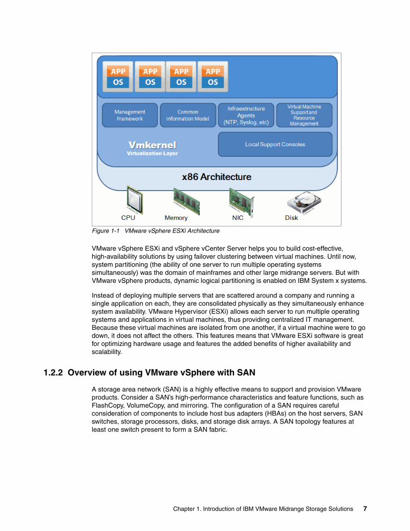
Figure 1-1 VMware vSphere ESXi Architecture
VMware vSphere ESXi and vSphere vCenter Server helps you to build cost-effective, high-availability solutions by using failover clustering between virtual machines. Until now, system partitioning (the ability of one server to run multiple operating systems simultaneously) was the domain of mainframes and other large midrange servers. But with VMware vSphere products, dynamic logical partitioning is enabled on IBM System x systems.
Instead of deploying multiple servers that are scattered around a company and running a single application on each, they are consolidated physically as they simultaneously enhance system availability. VMware Hypervisor (ESXi) allows each server to run multiple operating systems and applications in virtual machines, thus providing centralized IT management. Because these virtual machines are isolated from one another, if a virtual machine were to go down, it does not affect the others. This features means that VMware ESXi software is great for optimizing hardware usage and features the added benefits of higher availability and scalability.
1.2.2 Overview of using VMware vSphere with SAN
A storage area network (SAN) is a highly effective means to support and provision VMware products. Consider a SAN’s high-performance characteristics and feature functions, such as FlashCopy, VolumeCopy, and mirroring. The configuration of a SAN requires careful consideration of components to include host bus adapters (HBAs) on the host servers, SAN switches, storage processors, disks, and storage disk arrays. A SAN topology features at least one switch present to form a SAN fabric.
Chapter 1. Introduction of IBM VMware Midrange Storage Solutions 7
1.2.3 Benefits of using VMware vSphere with SAN
The use of a SAN with VMware vSphere includes the following benefits and capabilities:
� Data accessibility and system recovery is improved.
� Effectively store data redundantly and single points of failure are eliminated.
� Data Centers quickly negotiate system failures.
� VMware ESXi hypervisor provides multipathing by default and automatically supports virtual machines.
� Failure resistance to servers is extended.
� Makes high availability and automatic load balancing affordable for more applications than if dedicated hardware is used to provide standby services.
� Because shared main storage is available, building virtual machine clusters that use MSCS is possible.
� If virtual machines are used as standby systems for existing physical servers, shared storage is essential and a viable solution.
� Features vSphere vMotion capabilities to migrate virtual machines seamlessly from one host to another.
� The use of vSphere High Availability (HA) with a SAN for a cold standby solution guarantees an immediate, automatic failure response.
� vSphere Distributed Resource Scheduler (DRS) is used to migrate virtual machines from one host to another for load balancing.
� VMware DRS clusters put an VMware ESXi host into maintenance mode to allow the system to migrate all virtual machines that are running to other VMware ESXi hosts.
� Uses vSphere Storage vMotion as a storage tiering tool by moving data to different Datastores and types of storage platforms when virtual machine storage disks are moved to different locations with no downtime and are transparent to the virtual machine or the user.
The transportability and encapsulation of VMware virtual machines complements the shared nature of SAN storage. When virtual machines are on SAN-based storage, you shut down a virtual machine on one server and power it up on another server or suspend it on one server and resume operation on another server on the same network in a matter of minutes. With this ability, you migrate computing resources and maintain consistent shared access.
1.2.4 VMware vSphere and SAN use cases
The use of VMware vSphere with SAN is effective for the following tasks:
� Maintenance with zero downtime: When maintenance is performed, you use vSphere DRS or VMware vMotion to migrate virtual machines to other servers.
� Load balancing: vSphere vMotion or vSphere DRS is used to migrate virtual machines to other hosts for load balancing.
� Storage consolidation and simplification of storage layout: Host storage is not the most effective method to use available storage. Shared storage is more manageable for allocation and recovery.
� Disaster recovery: Storing all data on a SAN greatly facilitates the remote storage of data backups.
8 VMware Implementation with IBM System Storage DS5000
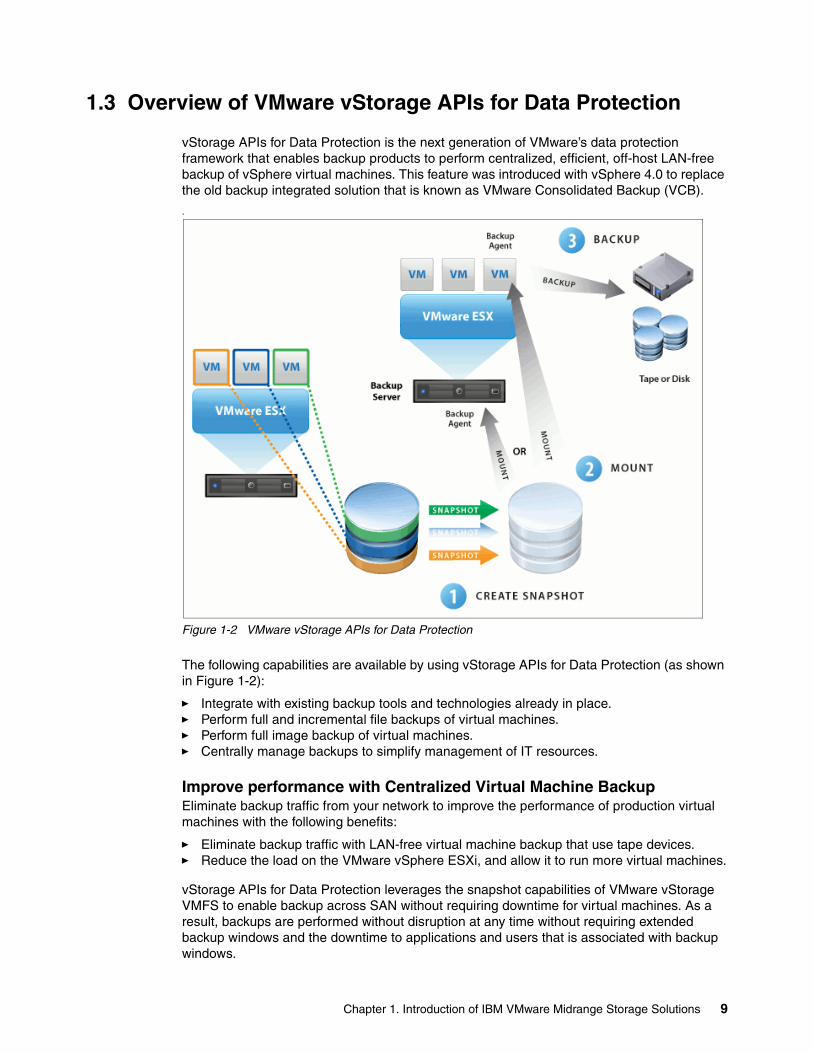
1.3 Overview of VMware vStorage APIs for Data Protection
vStorage APIs for Data Protection is the next generation of VMware’s data protection framework that enables backup products to perform centralized, efficient, off-host LAN-free backup of vSphere virtual machines. This feature was introduced with vSphere 4.0 to replace the old backup integrated solution that is known as VMware Consolidated Backup (VCB).
.
Figure 1-2 VMware vStorage APIs for Data Protection
The following capabilities are available by using vStorage APIs for Data Protection (as shown in Figure 1-2):
� Integrate with existing backup tools and technologies already in place.� Perform full and incremental file backups of virtual machines.� Perform full image backup of virtual machines.� Centrally manage backups to simplify management of IT resources.
Improve performance with Centralized Virtual Machine BackupEliminate backup traffic from your network to improve the performance of production virtual machines with the following benefits:
� Eliminate backup traffic with LAN-free virtual machine backup that use tape devices. � Reduce the load on the VMware vSphere ESXi, and allow it to run more virtual machines.
vStorage APIs for Data Protection leverages the snapshot capabilities of VMware vStorage VMFS to enable backup across SAN without requiring downtime for virtual machines. As a result, backups are performed without disruption at any time without requiring extended backup windows and the downtime to applications and users that is associated with backup windows.
Chapter 1. Introduction of IBM VMware Midrange Storage Solutions 9
vStorage APIs for Data Protection is designed for all editions of vSphere and is supported by many backup products, including Symantec NetBackup, CA ArcServe, IBM Tivoli Storage Manager, and VizionCore vRanger.
For more information, see this website:
http://www.vmware.com/products/vstorage-apis-for-data-protection/overview.html
1.4 Overview of VMware vCenter Site Recovery Manager
As shown in Figure 1-3 on page 11, VMware vCenter Site Recovery Manager (SRM) provides business continuity and disaster recovery protection for virtual environments. Protection extends from individually replicated datastores to an entire virtual site. VMware’s virtualization of the data center offers advantages that are applied to business continuity and disaster recovery.
The entire state of a virtual machine (memory, disk images, I/O, and device state) is encapsulated. Encapsulation enables the state of a virtual machine to be saved to a file. Saving the state of a virtual machine to a file allows the transfer of an entire virtual machine to another host.
Hardware independence eliminates the need for a complete replication of hardware at the recovery site. Hardware that is running VMware vSphere ESXi Server at one site provides business continuity and disaster recovery protection for hardware that is running VMware vSphere ESXi Server at another site. This configuration eliminates the cost of purchasing and maintaining a system that sits idle until disaster strikes.
Hardware independence allows an image of the system at the protected site to boot from disk at the recovery site in minutes or hours instead of days.
vCenter Site Recovery Manager leverages array-based replication between a protected site and a recovery site, such as the IBM DS Enhanced Remote Mirroring functionality. The workflow that is built into SRM automatically discovers which datastores are set up for replication between the protected and recovery sites. SRM is configured to support bidirectional protection between two sites.
vCenter Site Recovery Manager provides protection for the operating systems and applications that are encapsulated by the virtual machines that are running on VMware ESXi Server.
A vCenter Site Recovery Manager server must be installed at the protected site and at the recovery site. The protected and recovery sites must each be managed by their own vCenter Server. The SRM server uses the extensibility of the vCenter Server to provide the following features:
� Access control � Authorization � Custom events � Event-triggered alarms
10 VMware Implementation with IBM System Storage DS5000
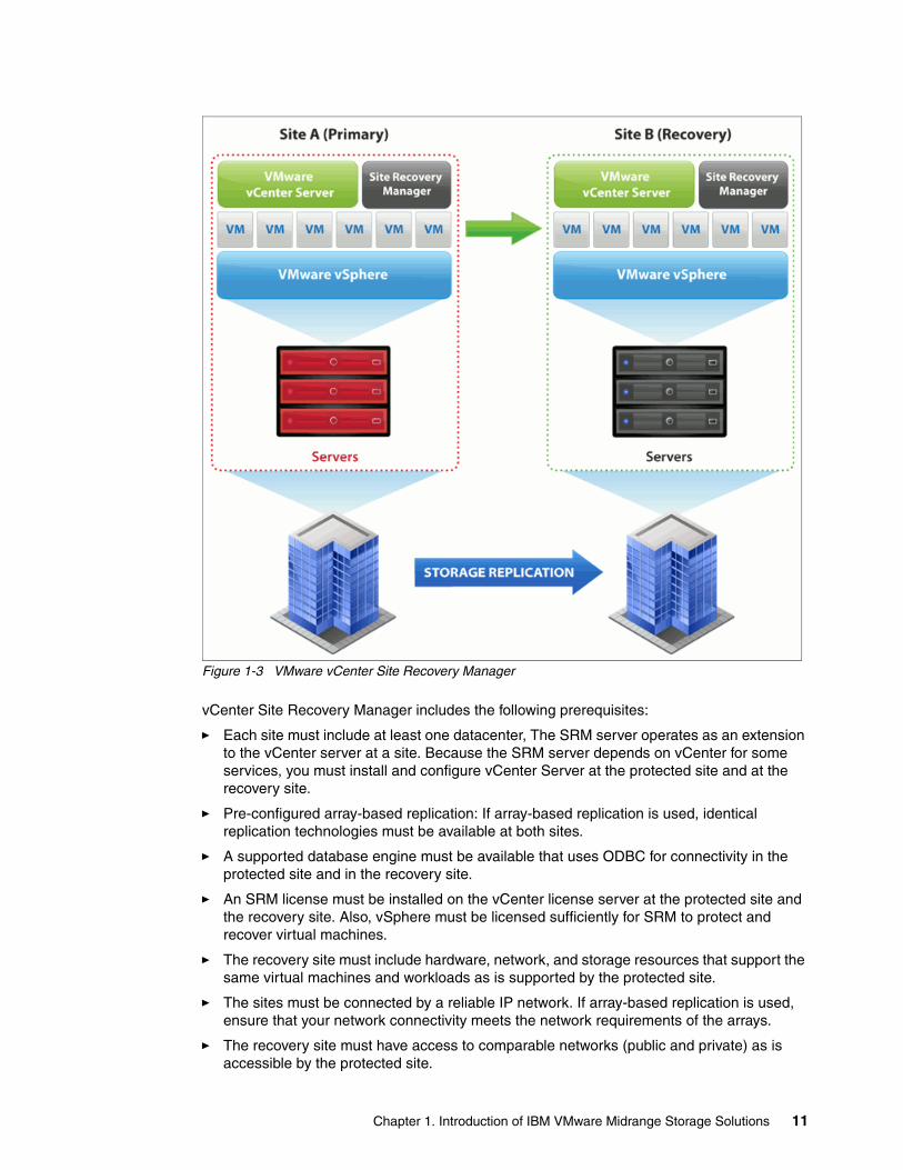
Figure 1-3 VMware vCenter Site Recovery Manager
vCenter Site Recovery Manager includes the following prerequisites:
� Each site must include at least one datacenter, The SRM server operates as an extension to the vCenter server at a site. Because the SRM server depends on vCenter for some services, you must install and configure vCenter Server at the protected site and at the recovery site.
� Pre-configured array-based replication: If array-based replication is used, identical replication technologies must be available at both sites.
� A supported database engine must be available that uses ODBC for connectivity in the protected site and in the recovery site.
� An SRM license must be installed on the vCenter license server at the protected site and the recovery site. Also, vSphere must be licensed sufficiently for SRM to protect and recover virtual machines.
� The recovery site must include hardware, network, and storage resources that support the same virtual machines and workloads as is supported by the protected site.
� The sites must be connected by a reliable IP network. If array-based replication is used, ensure that your network connectivity meets the network requirements of the arrays.
� The recovery site must have access to comparable networks (public and private) as is accessible by the protected site.
Chapter 1. Introduction of IBM VMware Midrange Storage Solutions 11
For more information, see this website:
http://www.vmware.com/products/site-recovery-manager/overview.html
For more information about updated product materials and guides, see this website:
http://www.ibmdsseries.com/
12 VMware Implementation with IBM System Storage DS5000
Chapter 2. Security Design of the VMware vSphere Infrastructure Architecture
In this chapter, we describe the security design and associated features of the VMware vSphere Infrastructure Architecture.
2
© Copyright IBM Corp. 2012. All rights reserved. 13
2.1 Introduction
VMware vSphere Infrastructure is the most widely deployed software suite for optimizing and managing IT environments through virtualization from the desktop to the data center. The only production-ready virtualization suite, vSphere Infrastructure is proven at more than 20,000 customers of all sizes, and is used in various environments and applications. vSphere Infrastructure delivers transformative cost savings and increased Operational Efficiency, flexibility, and IT service levels.
vSphere Infrastructure incorporates many features that address the following security concerns of the most demanding datacenter environments:
� A virtualization layer is designed from the ground up to run virtual machines in a secure manner and still provide high performance
� Compatibility with SAN security practices. vSphere Infrastructure enforces security policies with logical unit number (LUN) zoning and LUN masking.
� Implementation of secure networking features. VLAN tagging enhances network security by tagging and filtering network traffic on VLANs. Layer 2 network security policies enforce security for virtual machines at the Ethernet layer in a way that is not available with physical servers.
� Integration with Microsoft Active Directory. vSphere Infrastructure bases access controls on existing Microsoft Active Directory authentication mechanisms.
vSphere Infrastructure, the latest generation of VMware vSphere datacenter products, includes the following key enhancements that further address the security needs and challenges of modern IT organizations:
� Custom roles and permissions. vSphere Infrastructure enhances security and flexibility with user-defined roles. You restrict access to the entire inventory of virtual machines, resource pools, and servers by assigning users to these custom roles.
� Resource pool access control and delegation. vSphere Infrastructure secures resource allocation at other levels in the company. For example, when a top-level administrator makes a resource pool available to a department-level user, all virtual machine creation and management is performed by the department administrator within the boundaries that are assigned to the resource pool.
� Audit trails. vSphere Infrastructure maintains a record of significant configuration changes and the administrator who initiated each change. Reports are exported for event tracking.
� Session management. vSphere Infrastructure enables you to discover and, if necessary, terminate VCenter user sessions.
VMware implemented internal processes to ensure that VMware products meet the highest standards for security. The VMware Security Response Policy documents VMware’s commitments to resolving possible vulnerabilities in VMware products so that customers are assured that any such issues are corrected quickly. The VMware Technology Network (VMTN) Security Center is a one-stop shop for security-related issues that involve VMware products. The center helps you stay up-to-date on all current security issues and to understand considerations that are related to securing your virtual infrastructure.
For more information about the VMware Security Response Policy, see this website:
http://www.vmware.com/support/policies/security_response.html
14 VMware Implementation with IBM System Storage DS5000

For more information about VMware Technology Network (VMTN) Security Center, see this website:
http://www.vmware.com/technical-resources/security/index.html
The success of this architecture in providing a secure virtualization infrastructure is evidenced by the fact that many large, security-conscious customers from areas such as banking and defense chose to trust their mission-critical services to VMware virtualization.
From a security perspective, VMware vSphere Infrastructure consists of the following components:
� Virtualization layer, which consists of the following components:
– VMkernel, the virtual machine monitor (VMM)– Management framework– Common information model– Infrastructure agents– Virtual machine support and resource management– Local support consoles
� Virtual machines
� Virtual networking layer
2.2 Virtualization Layer
VMware vSphere ESXi presents a generic x86 platform by virtualizing four key hardware components: processor, memory, disk, and network. An operating system is installed into this virtualized platform. The virtualization layer or VMkernel, which runs into Hypervisor, is a kernel that is designed by VMware specifically to run virtual machines. It controls the hardware that is used by VMware ESXi Server hosts and schedules the allocation of hardware resources among the virtual machines.
Because the VMkernel is fully dedicated to supporting virtual machines and is not used for other purposes, the interface to the VMkernel is strictly limited to the API that is required to manage virtual machines. There are no public interfaces to VMkernel, and it cannot execute arbitrary code.
The VMkernel alternates among all the virtual machines on the host in running the virtual machine instructions on the processor. When a virtual machine’s execution is stopped, a context switch occurs. During the context switch, the processor register values are saved and the new context is loaded. When a virtual machine’s turn comes around again, the corresponding register state is restored.
Each virtual machine features an associated VMM. The VMM uses binary translation to modify the guest operating system kernel code so that the VMM runs in a less-privileged processor ring. This configuration is analogous to what a Java virtual machine does when it uses just-in-time translation. Also, the VMM virtualizes a chip set on which the guest operating system to runs. The device drivers in the guest cooperate with the VMM to access the devices in the virtual chip set. The VMM passes requests to the VMkernel to complete the device virtualization and support the requested operation.
Chapter 2. Security Design of the VMware vSphere Infrastructure Architecture 15
2.2.1 Local Support Consoles
In VMware vSphere ESXi 5, the Console OS (which is provided in all known prior versions of ESX) are removed. All VMware agents are ported to run directly on VMkernel. The Infrastructure services are provided natively through modules that are included with the vmkernel. Other authorized third-party modules, such as hardware drivers and hardware monitoring components, also run in vmkernel. Only modules that are digitally signed by VMware are allowed on the system, which creates a tightly locked-down architecture. Preventing arbitrary code from running on the ESXi host greatly improves the security of the system.
For more information about the Support Console improvements, see this website:
http://www.vmware.com/products/vsphere/esxi-and-esx/compare.html
Securing Local Support ConsolesTo protect the host against unauthorized intrusion and misuse, VMware imposes constraints on several parameters, settings, and activities. You loosen the constraints to meet your configuration needs. However, if the constraints are modified, make sure that you are working in a trusted environment and take enough security measures to protect the network as a whole and the devices that are connected to the host.
Consider the following recommendations when host security and administration is evaluated:
� Limit user access
To improve security, restrict user access to the management interface and enforce access security policies, such as setting up password restrictions. The ESXi Shell includes privileged access to certain parts of the host. Therefore, provide only trusted users with ESXi Shell login access. Also, strive to run only the essential processes, services, and agents, such as virus checkers and virtual machine backups.
� Use the vSphere Client to administer your ESXi hosts
Whenever possible, use the vSphere Client or a third-party network management tool to administer your ESXi hosts instead of working through the command-line interface as the root user. By using the vSphere Client, you limit the accounts with access to the ESXi Shell, safely delegate responsibilities, and set up roles that prevent administrators and users from using capabilities that they do not need.
� Use only VMware sources to upgrade ESXi components
The host runs various third-party packages to support management interfaces or tasks that you must perform. VMware does not support upgrading these packages from anything other than a VMware source. If you use a download or patch from another source, you might compromise management interface security or functions. Regularly check third-party vendor sites and the VMware knowledge base for security alerts.
Important: The VMM that is used by VMware ESXi is the same as the VMM that is used by other VMware products that run on host operating systems, such as VMware Workstation or VMware Server. Therefore, all comments that are related to the VMM also apply to all VMware virtualization products.
16 VMware Implementation with IBM System Storage DS5000
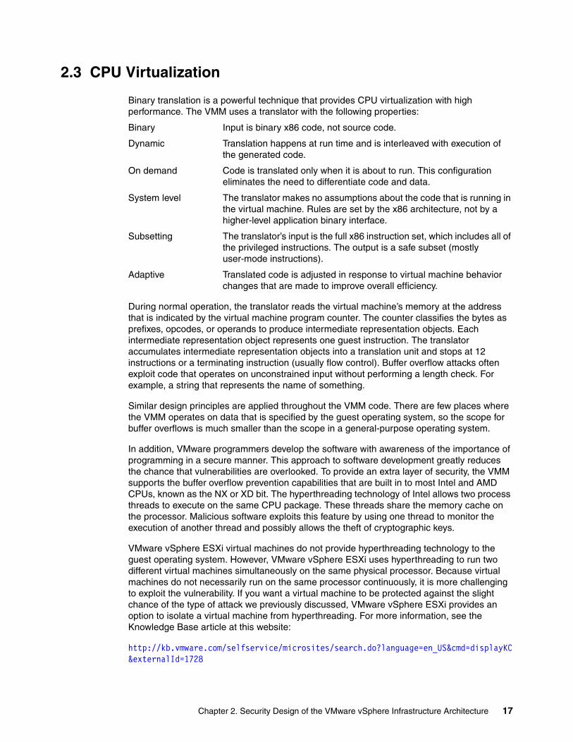
2.3 CPU Virtualization
Binary translation is a powerful technique that provides CPU virtualization with high performance. The VMM uses a translator with the following properties:
Binary Input is binary x86 code, not source code.
Dynamic Translation happens at run time and is interleaved with execution of the generated code.
On demand Code is translated only when it is about to run. This configuration eliminates the need to differentiate code and data.
System level The translator makes no assumptions about the code that is running in the virtual machine. Rules are set by the x86 architecture, not by a higher-level application binary interface.
Subsetting The translator’s input is the full x86 instruction set, which includes all of the privileged instructions. The output is a safe subset (mostly user-mode instructions).
Adaptive Translated code is adjusted in response to virtual machine behavior changes that are made to improve overall efficiency.
During normal operation, the translator reads the virtual machine’s memory at the address that is indicated by the virtual machine program counter. The counter classifies the bytes as prefixes, opcodes, or operands to produce intermediate representation objects. Each intermediate representation object represents one guest instruction. The translator accumulates intermediate representation objects into a translation unit and stops at 12 instructions or a terminating instruction (usually flow control). Buffer overflow attacks often exploit code that operates on unconstrained input without performing a length check. For example, a string that represents the name of something.
Similar design principles are applied throughout the VMM code. There are few places where the VMM operates on data that is specified by the guest operating system, so the scope for buffer overflows is much smaller than the scope in a general-purpose operating system.
In addition, VMware programmers develop the software with awareness of the importance of programming in a secure manner. This approach to software development greatly reduces the chance that vulnerabilities are overlooked. To provide an extra layer of security, the VMM supports the buffer overflow prevention capabilities that are built in to most Intel and AMD CPUs, known as the NX or XD bit. The hyperthreading technology of Intel allows two process threads to execute on the same CPU package. These threads share the memory cache on the processor. Malicious software exploits this feature by using one thread to monitor the execution of another thread and possibly allows the theft of cryptographic keys.
VMware vSphere ESXi virtual machines do not provide hyperthreading technology to the guest operating system. However, VMware vSphere ESXi uses hyperthreading to run two different virtual machines simultaneously on the same physical processor. Because virtual machines do not necessarily run on the same processor continuously, it is more challenging to exploit the vulnerability. If you want a virtual machine to be protected against the slight chance of the type of attack we previously discussed, VMware vSphere ESXi provides an option to isolate a virtual machine from hyperthreading. For more information, see the Knowledge Base article at this website:
http://kb.vmware.com/selfservice/microsites/search.do?language=en_US&cmd=displayKC&externalId=1728
Chapter 2. Security Design of the VMware vSphere Infrastructure Architecture 17
Hardware manufacturers are incorporating CPU virtualization capabilities into processors. Although the first generation of these processors does not perform as well as VMware’s software-based binary translator, VMware continues to work with the manufacturers and make appropriate use of their technology as it evolves.
2.4 Memory Virtualization
The RAM that is allocated to a virtual machine by the VMM is defined by the virtual machine’s BIOS settings. The memory is allocated by the VMkernel when it defines the resources to be used by the virtual machine. A guest operating system uses physical memory that is allocated to it by the VMkernel and defined in the virtual machine’s configuration file.
The operating system that executes within a virtual machine expects a zero-based physical address space, as provided by real hardware. The VMM gives each virtual machine the illusion that it is using such an address space and virtualizing physical memory by adding an extra level of address translation. A machine address refers to actual hardware memory, and a physical address is a software abstraction that is used to provide the illusion of hardware memory to a virtual machine. (The proceeding uses of the term physical in this context highlights this deviation from the usual meaning of the term.)
The VMM maintains a pmap data structure for each virtual machine to translate physical page numbers (PPNs) to machine page numbers (MPNs). Virtual machine instructions that manipulate guest operating system page tables or translation lookaside buffer contents are intercepted, which prevents updates to the hardware memory management unit. Separate shadow page tables that contain virtual-to-machine page mappings are maintained for use by the processor and are kept consistent with the physical-to-machine mappings in the pmap. This approach permits ordinary memory references to execute without more overhead because the hardware translation lookaside buffer caches direct virtual-to-machine address translation reads from the shadow page table. When memory management capabilities are enabled in hardware, VMware takes full advantage of the new capabilities and maintains the same strict adherence to isolation.
The extra level of indirection in the memory system is powerful. The server remaps a physical page by changing its PPN-to-MPN mapping in a manner that is transparent to the virtual machine. It also allows the VMM to interpose on guest memory accesses. Any attempt by the operating system or any application that is running inside a virtual machine to address memory outside of what is allocated by the VMM causes a fault to be delivered to the guest operating system. This fault often results in an immediate system crash, panic, or halt in the virtual machine, depending on the operating system. When a malicious guest operating system attempts I/O to an address space that is outside normal boundaries, it is often referred to as hyperspacing.
When a virtual machine needs memory, each memory page is zeroed out by the VMkernel before it is handed to the virtual machine. Normally, the virtual machine then features exclusive use of the memory page, and no other virtual machine touches or even see it. The exception is when transparent page sharing (TPS) is in effect.
18 VMware Implementation with IBM System Storage DS5000
TPS is a technique for using memory resources more efficiently. Memory pages that are identical in two or more virtual machines are stored after they are on the host system’s RAM. Each virtual machine features read-only access. Such shared pages are common; for example, if many virtual machines on the same host run the same operating system. When any one virtual machine tries to modify a shared page, it gets its own private copy. Because shared memory pages are marked copy-on-write, it is impossible for one virtual machine to leak private information to another through this mechanism. Transparent page sharing is controlled by the VMkernel and VMM and cannot be compromised by virtual machines. It also is disabled on a per-host or per-virtual machine basis.
Guest balloon is a driver that is part of the VMware tools and it is loaded into the guest operating system as a pseudo-device driver. Also known as ballooning, the balloon driver process (vmmemctl) recognizes when a VM is idle and exerts artificial pressure on the guest operating system, which causes it to swap out its memory to disk. If the hypervisor needs to reclaim virtual machine memory, it sets a proper target balloon size for the balloon driver, making it expand by allocating guest physical pages within the virtual machine.
Ballooning is a different memory reclamation technique that is compared to page sharing, but working together, TPS and the balloon driver let ESX Server comfortably support memory over-commitment.
ESXi includes a third memory reclaim technology that is known as hypervisor swapping that is used in the cases where ballooning and TPS are not sufficient to reclaim memory, To support this technology, when a virtual machine is started, the hypervisor creates a separate swap file for the virtual machine. Then, if necessary, the hypervisor directly swaps out guest physical memory to the swap file, which frees host physical memory for other virtual machines.
For more information about memory reclamation technologies, see the Understanding Memory Resource Management in VMware ESX Server document at this website:
http://www.vmware.com/files/pdf/perf-vsphere-memory_management.pdf
2.5 Virtual Machines
Virtual machines are the containers in which guest operating systems and their applications run. By design, all VMware virtual machines are isolated from one another. Virtual machine isolation is imperceptible to the guest operating system. Even a user with system administrator privileges or kernel system-level access on a virtual machine’s guest operating system cannot breach this layer of isolation to access another virtual machine without the privileges that are explicitly granted by the VMware vSphere ESXi system administrator.
This isolation enables multiple virtual machines to run securely as they share hardware and ensures the machines’ ability to access hardware and their uninterrupted performance. For example, if a guest operating system that is running in a virtual machine crashes, other virtual machines on the same VMware vSphere ESXi host continue to run. The guest operating system crash has no effect on the following performance issues:
� The ability of users to access the other virtual machines� The ability of the running virtual machines to access the resources they need� The performance of the other virtual machines
Chapter 2. Security Design of the VMware vSphere Infrastructure Architecture 19
Each virtual machine is isolated from other virtual machines that are running on the same hardware. Although virtual machines do share physical resources, such as CPU, memory, and I/O devices, a guest operating system in an individual virtual machine cannot detect any device other than the virtual devices that are made available to it.
Because the VMkernel and VMM mediate access to the physical resources and all physical hardware access takes place through the VMkernel, virtual machines cannot circumvent this level of isolation. Just as a physical machine communicates with other machines in a network only through a network adapter, a virtual machine communicates with other virtual machines that are running on the same VMware vSphere ESXi host only through a virtual switch. Also, a virtual machine communicates with the physical network (including virtual machines on other VMware vSphere ESXi hosts) only through a physical network adapter.
In considering virtual machine isolation in a network context, you apply the following rules:
� If a virtual machine does not share a virtual switch with any other virtual machine, it is isolated from other virtual networks within the host.
� If no physical network adapter is configured for a virtual machine, the virtual machine is isolated from any physical networks.
� If you use the same safeguards (firewalls, antivirus software, and so on) to protect a virtual machine from the network as you do for a physical machine, the virtual machine is as secure as the physical machine.
You further protect virtual machines by setting up resource reservations and limits on the ESXi host. For example, through the fine-grained resource controls that are available in ESXi host, you configure a virtual machine so that it always gets at least 10 percent of the host’s CPU resources, but never more than 20 percent. Resource reservations and limits protect virtual machines from performance degradation if another virtual machine tries to consume too many resources on shared hardware. For example, if one of the virtual machines on an ESXi host is incapacitated by a denial-of-service or distributed denial-of-service attack, a resource limit on that machine prevents the attack from taking up so many hardware resources that the other virtual machines are also affected. Similarly, a resource reservation on each of the virtual machines ensures that, in the event of high resource demands by the virtual machine that is targeted by the denial-of-service attack, all of the other virtual machines still include enough resources to operate.
By default, VMware vSphere ESXi imposes a form of resource reservation by applying a distribution algorithm that divides the available host resources equally among the virtual machines. The algorithm also keeps a certain percentage of resources for use by system components, such as the service console. This default behavior provides a degree of natural protection from denial-of-service and distributed denial-of-service attacks. You set specific resource reservations and limits on an individual basis if you want to customize the default behavior so that the distribution is not equal across all virtual machines on the host.
2.6 Virtual Networking Layer
The virtual networking layer consists of the virtual network devices through which virtual machines and the service console interface with the rest of the network. VMware vSphere ESXi Server relies on the virtual networking layer to support communications between virtual machines and their users. In addition, VMware vSphere ESXi Server hosts use the virtual networking layer to communicate with iSCSI SANs, NAS storage, and so on. The virtual networking layer includes virtual network adapters and the virtual switches.
20 VMware Implementation with IBM System Storage DS5000
2.6.1 Virtual Standard Switches
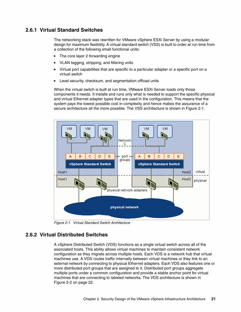
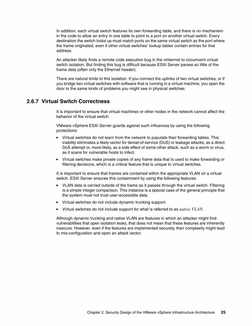
The networking stack was rewritten for VMware vSphere ESXi Server by using a modular design for maximum flexibility. A virtual standard switch (VSS) is built to order at run time from a collection of the following small functional units:
� The core layer 2 forwarding engine
� VLAN tagging, stripping, and filtering units
� Virtual port capabilities that are specific to a particular adapter or a specific port on a virtual switch
� Level security, checksum, and segmentation offload units
When the virtual switch is built at run time, VMware ESXi Server loads only those components it needs. It installs and runs only what is needed to support the specific physical and virtual Ethernet adapter types that are used in the configuration. This means that the system pays the lowest possible cost in complexity and hence makes the assurance of a secure architecture all the more possible. The VSS architecture is shown in Figure 2-1.
Figure 2-1 Virtual Standard Switch Architecture
2.6.2 Virtual Distributed Switches
A vSphere Distributed Switch (VDS) functions as a single virtual switch across all of the associated hosts. This ability allows virtual machines to maintain consistent network configuration as they migrate across multiple hosts. Each VDS is a network hub that virtual machines use. A VDS routes traffic internally between virtual machines or they link to an external network by connecting to physical Ethernet adapters. Each VDS also features one or more distributed port groups that are assigned to it. Distributed port groups aggregate multiple ports under a common configuration and provide a stable anchor point for virtual machines that are connecting to labeled networks. The VDS architecture is shown in Figure 2-2 on page 22.
Chapter 2. Security Design of the VMware vSphere Infrastructure Architecture 21
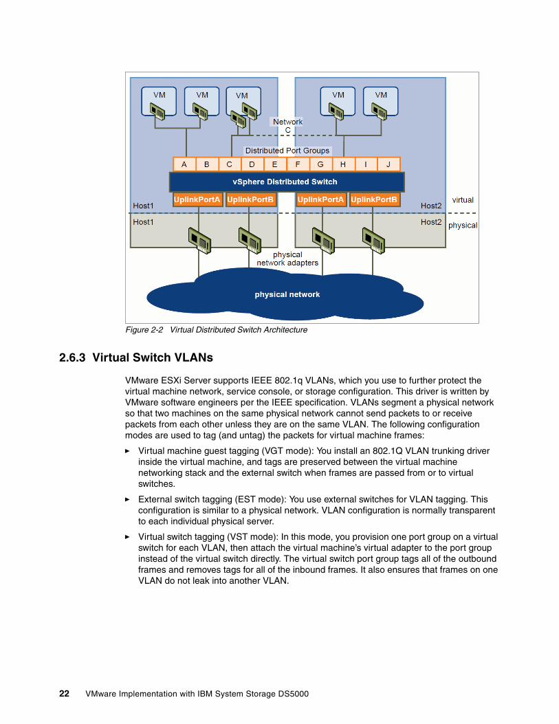
Figure 2-2 Virtual Distributed Switch Architecture
2.6.3 Virtual Switch VLANs
VMware ESXi Server supports IEEE 802.1q VLANs, which you use to further protect the virtual machine network, service console, or storage configuration. This driver is written by VMware software engineers per the IEEE specification. VLANs segment a physical network so that two machines on the same physical network cannot send packets to or receive packets from each other unless they are on the same VLAN. The following configuration modes are used to tag (and untag) the packets for virtual machine frames:
� Virtual machine guest tagging (VGT mode): You install an 802.1Q VLAN trunking driver inside the virtual machine, and tags are preserved between the virtual machine networking stack and the external switch when frames are passed from or to virtual switches.
� External switch tagging (EST mode): You use external switches for VLAN tagging. This configuration is similar to a physical network. VLAN configuration is normally transparent to each individual physical server.
� Virtual switch tagging (VST mode): In this mode, you provision one port group on a virtual switch for each VLAN, then attach the virtual machine’s virtual adapter to the port group instead of the virtual switch directly. The virtual switch port group tags all of the outbound frames and removes tags for all of the inbound frames. It also ensures that frames on one VLAN do not leak into another VLAN.
22 VMware Implementation with IBM System Storage DS5000
2.6.4 Virtual Ports
The virtual ports in vSphere ESXi Server provide a rich control channel for communication with the virtual Ethernet adapters that are attached to them. ESXi Server virtual ports know authoritatively what the configured receive filters are for virtual Ethernet adapters that are attached to them. This capability means that no learning is required to populate forwarding tables.
Virtual ports also know authoritatively the hard configuration of the virtual Ethernet adapters that are attached to them. This capability makes it possible to set policies such as forbidding MAC address changes by the guest and rejecting forged MAC address transmission because the virtual switch port knows what is burned into ROM (stored in the configuration file, outside control of the guest operating system).
The policies that are available in virtual ports are much harder to implement (if they are possible at all) with physical switches. The ACLs must be manually programmed into the switch port, or weak assumptions such as “first MAC seen is assumed to be correct” must be relied upon.
The port groups that are used in ESXi Servers do not include a counterpart in physical networks. Think of the groups as templates for creating virtual ports with particular sets of specifications. Because virtual machines move from host to host, ESXi Server needs a reliable way to specify, through a layer of indirection, that a virtual machine must include a particular type of connectivity on every host on which it might run. Port groups provide this layer of indirection and enable the vSphere Infrastructure to provide consistent network access to a virtual machine, wherever it runs.
Port groups are user-named objects that contain the following configuration information to provide persistent and consistent network access for virtual Ethernet adapters:
� Virtual switch name� VLAN IDs and policies for tagging and filtering� Teaming policy� Layer security options� Traffic shaping parameters
Port groups provide a way to define and enforce security policies for virtual networking, as shown in Figure 2-3 on page 24.
Chapter 2. Security Design of the VMware vSphere Infrastructure Architecture 23
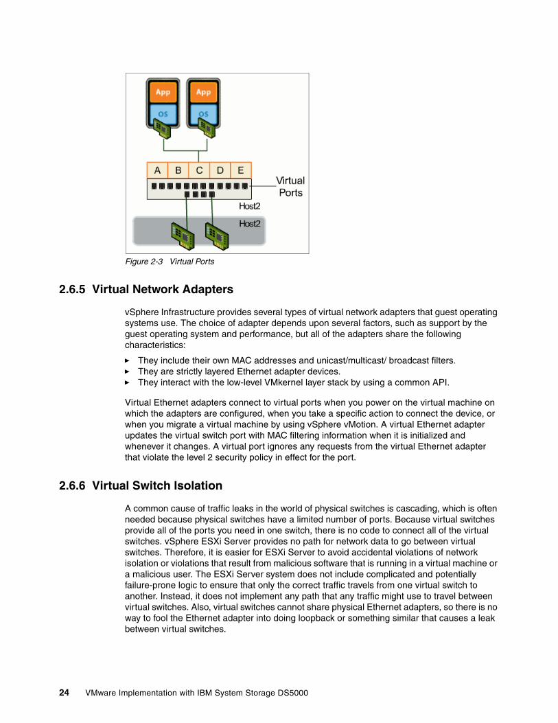
Figure 2-3 Virtual Ports
2.6.5 Virtual Network Adapters
vSphere Infrastructure provides several types of virtual network adapters that guest operating systems use. The choice of adapter depends upon several factors, such as support by the guest operating system and performance, but all of the adapters share the following characteristics:
� They include their own MAC addresses and unicast/multicast/ broadcast filters.� They are strictly layered Ethernet adapter devices.� They interact with the low-level VMkernel layer stack by using a common API.
Virtual Ethernet adapters connect to virtual ports when you power on the virtual machine on which the adapters are configured, when you take a specific action to connect the device, or when you migrate a virtual machine by using vSphere vMotion. A virtual Ethernet adapter updates the virtual switch port with MAC filtering information when it is initialized and whenever it changes. A virtual port ignores any requests from the virtual Ethernet adapter that violate the level 2 security policy in effect for the port.
2.6.6 Virtual Switch Isolation
A common cause of traffic leaks in the world of physical switches is cascading, which is often needed because physical switches have a limited number of ports. Because virtual switches provide all of the ports you need in one switch, there is no code to connect all of the virtual switches. vSphere ESXi Server provides no path for network data to go between virtual switches. Therefore, it is easier for ESXi Server to avoid accidental violations of network isolation or violations that result from malicious software that is running in a virtual machine or a malicious user. The ESXi Server system does not include complicated and potentially failure-prone logic to ensure that only the correct traffic travels from one virtual switch to another. Instead, it does not implement any path that any traffic might use to travel between virtual switches. Also, virtual switches cannot share physical Ethernet adapters, so there is no way to fool the Ethernet adapter into doing loopback or something similar that causes a leak between virtual switches.
24 VMware Implementation with IBM System Storage DS5000
In addition, each virtual switch features its own forwarding table, and there is no mechanism in the code to allow an entry in one table to point to a port on another virtual switch. Every destination the switch looks up must match ports on the same virtual switch as the port where the frame originated, even if other virtual switches’ lookup tables contain entries for that address.
An attacker likely finds a remote code execution bug in the vmkernel to circumvent virtual switch isolation. But finding this bug is difficult because ESXi Server parses so little of the frame data (often only the Ethernet header).
There are natural limits to this isolation. If you connect the uplinks of two virtual switches, or if you bridge two virtual switches with software that is running in a virtual machine, you open the door to the same kinds of problems you might see in physical switches.
2.6.7 Virtual Switch Correctness
It is important to ensure that virtual machines or other nodes in the network cannot affect the behavior of the virtual switch.
VMware vSphere ESXi Server guards against such influences by using the following protections:
� Virtual switches do not learn from the network to populate their forwarding tables. This inability eliminates a likely vector for denial-of-service (DoS) or leakage attacks, as a direct DoS attempt or, more likely, as a side effect of some other attack, such as a worm or virus, as it scans for vulnerable hosts to infect.
� Virtual switches make private copies of any frame data that is used to make forwarding or filtering decisions, which is a critical feature that is unique to virtual switches.
It is important to ensure that frames are contained within the appropriate VLAN on a virtual switch. ESXi Server ensures this containment by using the following features:
� VLAN data is carried outside of the frame as it passes through the virtual switch. Filtering is a simple integer comparison. This instance is a special case of the general principle that the system must not trust user-accessible data.
� Virtual switches do not include dynamic trunking support.
� Virtual switches do not include support for what is referred to as native VLAN.
Although dynamic trunking and native VLAN are features in which an attacker might find vulnerabilities that open isolation leaks, that does not mean that these features are inherently insecure. However, even if the features are implemented securely, their complexity might lead to mis-configuration and open an attack vector.
Chapter 2. Security Design of the VMware vSphere Infrastructure Architecture 25
2.7 Virtualized Storage
VMware vSphere ESXi Server implements a streamlined path to provide high-speed and isolated I/O for performance-critical network and disk devices. An I/O request that is issued by a guest operating system first goes to the appropriate driver in the virtual machine. VMware vSphere ESXi Server provides the following emulation of storage controllers:
� LSI Logic or BusLogic SCSI devices
This controller is used when the corresponding driver is loaded into the guest operating system as an LSI Logic or as a BusLogic driver. The driver often turns the I/O requests into accesses to I/O ports to communicate to the virtual devices by using privileged IA-32 IN and OUT instructions. These instructions are trapped by the virtual machine monitor and then handled by device emulation code in the virtual machine monitor that is based on the specific I/O port that is accessed. The virtual machine monitor then calls device-independent network or disk code to process the I/O. For disk I/O, VMware ESXi Server maintains a queue of pending requests per virtual machine for each target SCSI device. The disk I/O requests for a single target are processed in round-robin fashion across virtual machines by default. The I/O requests are then sent down to the device driver that is loaded into ESXi Server for the specific device on the physical machine.
� Paravirtual SCSI (PVSCSI) adapter
Following the same I/O redirection concept, vmware provides the paravirtualized SCSI adapters, where this high-performance storage adapter provides better throughput and lower CPU utilization for virtual machines. It is best-suited for environments in which guest applications are I/O-intensive and use applications such as Microsoft SQL Server, Oracle MySQL, and IBM DB2®.
2.8 SAN security
A host that runs VMware vSphere ESXi Server is attached to a Fibre Channel SAN in the same way that any other host is attached. It uses Fibre Channel HBAs with the drivers for those HBAs that are installed in the software layer that interacts directly with the hardware. In environments that do not include virtualization software, the drivers are installed on the operating system. For vSphere ESXi Server, the drivers are installed in the VMkernel (Virtualization Layer). vSphere ESXi Server includes the native vSphere Virtual Machine File System (vSphere VMFS), which is a high-performance cluster file system and volume manager that creates and manages virtual volumes on top of the LUNs that are presented to the ESXi Server host. Those virtual volumes, which are often referred to as Datastores or virtual disks, are allocated to specific virtual machines.
Virtual machines have no knowledge or understanding of Fibre Channel. The only storage that is available to virtual machines is on SCSI devices. A virtual machine does not include virtual Fibre Channel HBAs. Instead, a virtual machine includes only virtual SCSI adapters. Each virtual machine sees only the virtual disks that are presented to it on its virtual SCSI adapters. This isolation is complete regarding security and performance. A VMware virtual machine has no visibility into the WWN (worldwide name), the physical Fibre Channel HBAs, or the target ID or other information about the LUNs upon which its virtual disks reside. The virtual machine is isolated to such a degree that software that executes in the virtual machine cannot detect that it is running on a SAN fabric. Even multipathing is handled in a way that is transparent to a virtual machine. Virtual machines also are configured to limit the bandwidth that they use to communicate with storage devices. This limitation prevents the possibility of a denial-of-service attack against other virtual machines on the same host by one virtual machine that takes over the Fibre Channel HBA.
26 VMware Implementation with IBM System Storage DS5000
Consider the example of running a Microsoft Windows operating system inside a vSphere ESXi virtual machine. The virtual machine sees only the virtual disks that the ESXi Server administrator chooses at the time that the virtual machine is configured. Configuring a virtual machine to see only certain virtual disks is effectively LUN masking in the virtualized environment. It features the same security benefits as LUN masking in the physical world, and it is done with another set of tools.
Software that is running in the virtual machine, including the Windows operating system, is aware of only the virtual disks that are attached to the virtual machine. Even if the Windows operating system attempts to issue a SCSI command (for example, Report LUNs) to discover other targets, vSphere ESXi Server prevents it from discovering any SCSI information that is not appropriate to its isolated and virtualized view of its storage environment. Complexities in the storage environment arise when a cluster of vSphere ESXi Server hosts is accessing common targets or LUNs. The vSphere VMFS file system ensures that all of the hosts in the cluster cooperate to ensure correct permissions and safe access to the VMFS volumes. File locks are stored on disk as part of the volume metadata, and all ESXi Server hosts that use the volumes are aware of the ownership. File ownership and various distributed file system activities are rendered exclusive and atomic by the use of standard SCSI reservation primitives. Each virtual disk (sometimes referred to as a .vmdk file) is exclusively owned by a single powered-on virtual machine. No other virtual machine on the same or another ESXi Server host is allowed to access that virtual disk. This situation does not change fundamentally when there is a cluster of vSphere ESXi Server hosts with multiple virtual machines powered on and accessing virtual disks on a single VMFS volume. Because of this fact, vSphere vMotion, which enables live migration of a virtual machine from one ESXi Server host to another, is a protected operation.
2.9 VMware vSphere vCenter Server
VMware vSphere vCenter Server provides a central place where almost all management functions of VMware Infrastructure are performed. vCenter relies on Windows security controls and therefore must reside on a properly managed server with network access limited to those ports that are necessary for it to interoperate with all of the other VMware vSphere components and features. It is role-based and tied to Active Directory or heritage NT domains, which makes it unnecessary to create custom user accounts for it. vCenter also keeps records of nearly every event in the vSphere ESXi Server system, so audit trails for compliance are generated.
vSphere vCenter manages the creation and enforcement of resource pools, which are used to partition available CPU and memory resources. A resource pool contains child resource pools and virtual machines, which allow the creation of a hierarchy of shared resources. By using resource pools, you delegate control over resources of a host or cluster. When a top-level administrator makes a resource pool available to a department-level administrator, that administrator performs all of the virtual machine creation and management within the boundaries of the resources to which the resource pool is entitled. More importantly, vSphere vCenter enforces isolation between resources pools so that resource usage in one pool does not affect the availability of resources in another pool. This action provides a coarser level of granularity for containment of resource abuse and the granularity that is provided on the vSphere ESXi Server host level.
vSphere vCenter features a sophisticated system of roles and permissions to allow fine-grained determination of authorization for administrative and user tasks that are based on user or group and inventory items, such as clusters, resource pools, and hosts. By using this system, you ensure that only the minimum necessary privileges are assigned to people to prevent unauthorized access or modification.
Chapter 2. Security Design of the VMware vSphere Infrastructure Architecture 27
VMware vCenter Servers let administrators rapidly provision VMs and hosts by using standardized templates, and ensures compliance with vSphere host configurations and host and VM patch levels with automated remediation. VMware vCenter Server also gives administrators control over key capabilities, such as vSphere vMotion, Distributed Resource Scheduler, High Availability, and Fault Tolerance.
For more information about vSphere vCenter architecture and features, see this website:
http://www.vmware.com/files/pdf/techpaper/Whats-New-VMware-vCenter-Server-50-Technical-Whitepaper.pdf
28 VMware Implementation with IBM System Storage DS5000
Chapter 3. Planning the VMware vSphere Storage System Design
Careful planning is essential to any new storage installation. Choosing the correct equipment and software and knowing the correct settings for your installation is challenging. Well-thought out design and planning before the implementation helps you get the most of your investment for the present and protect it for the future. Considerations include throughput capability, the size of and resources that are necessary to handle the volume of traffic, and the required capacity.
In this chapter, we provide guidelines to help you in the planning of your storage systems for your VMware vSphere environment.
3
© Copyright IBM Corp. 2012. All rights reserved. 29
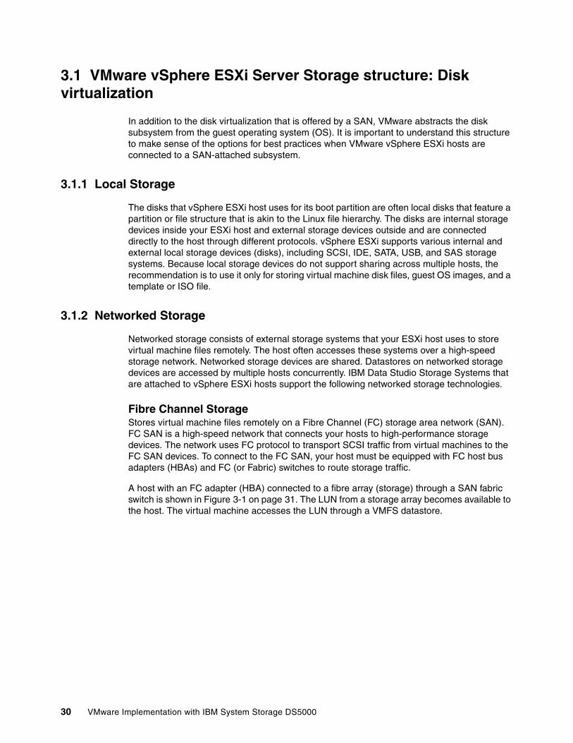
3.1 VMware vSphere ESXi Server Storage structure: Disk virtualization
In addition to the disk virtualization that is offered by a SAN, VMware abstracts the disk subsystem from the guest operating system (OS). It is important to understand this structure to make sense of the options for best practices when VMware vSphere ESXi hosts are connected to a SAN-attached subsystem.
3.1.1 Local Storage
The disks that vSphere ESXi host uses for its boot partition are often local disks that feature a partition or file structure that is akin to the Linux file hierarchy. The disks are internal storage devices inside your ESXi host and external storage devices outside and are connected directly to the host through different protocols. vSphere ESXi supports various internal and external local storage devices (disks), including SCSI, IDE, SATA, USB, and SAS storage systems. Because local storage devices do not support sharing across multiple hosts, the recommendation is to use it only for storing virtual machine disk files, guest OS images, and a template or ISO file.
3.1.2 Networked Storage
Networked storage consists of external storage systems that your ESXi host uses to store virtual machine files remotely. The host often accesses these systems over a high-speed storage network. Networked storage devices are shared. Datastores on networked storage devices are accessed by multiple hosts concurrently. IBM Data Studio Storage Systems that are attached to vSphere ESXi hosts support the following networked storage technologies.
Fibre Channel StorageStores virtual machine files remotely on a Fibre Channel (FC) storage area network (SAN). FC SAN is a high-speed network that connects your hosts to high-performance storage devices. The network uses FC protocol to transport SCSI traffic from virtual machines to the FC SAN devices. To connect to the FC SAN, your host must be equipped with FC host bus adapters (HBAs) and FC (or Fabric) switches to route storage traffic.
A host with an FC adapter (HBA) connected to a fibre array (storage) through a SAN fabric switch is shown in Figure 3-1 on page 31. The LUN from a storage array becomes available to the host. The virtual machine accesses the LUN through a VMFS datastore.
30 VMware Implementation with IBM System Storage DS5000
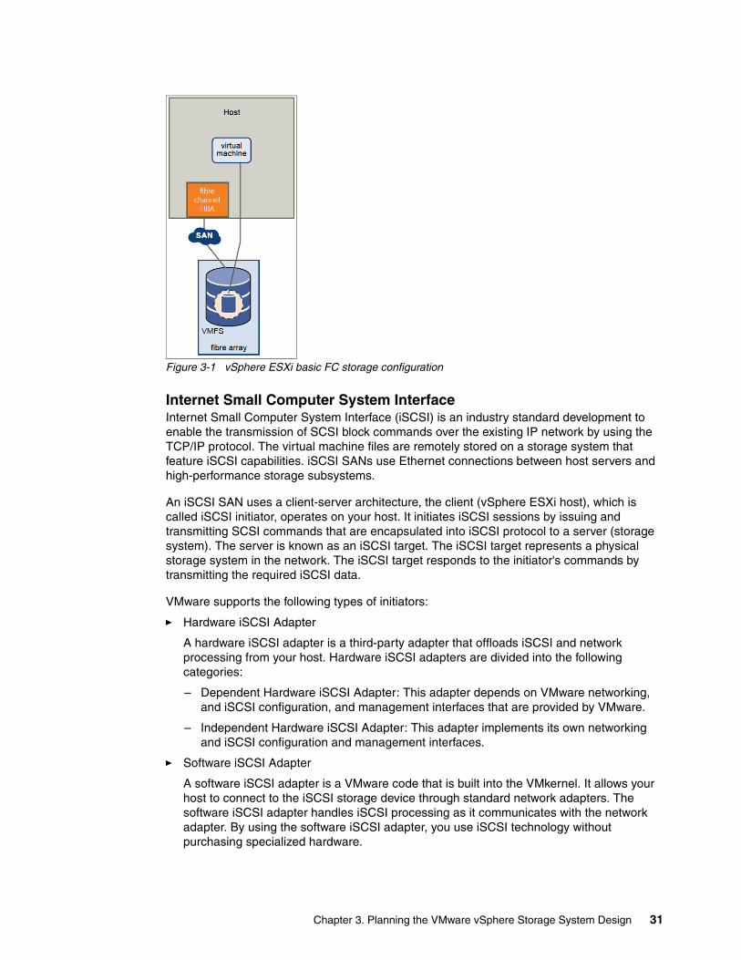
Figure 3-1 vSphere ESXi basic FC storage configuration
Internet Small Computer System InterfaceInternet Small Computer System Interface (iSCSI) is an industry standard development to enable the transmission of SCSI block commands over the existing IP network by using the TCP/IP protocol. The virtual machine files are remotely stored on a storage system that feature iSCSI capabilities. iSCSI SANs use Ethernet connections between host servers and high-performance storage subsystems.
An iSCSI SAN uses a client-server architecture, the client (vSphere ESXi host), which is called iSCSI initiator, operates on your host. It initiates iSCSI sessions by issuing and transmitting SCSI commands that are encapsulated into iSCSI protocol to a server (storage system). The server is known as an iSCSI target. The iSCSI target represents a physical storage system in the network. The iSCSI target responds to the initiator's commands by transmitting the required iSCSI data.
VMware supports the following types of initiators:
� Hardware iSCSI Adapter
A hardware iSCSI adapter is a third-party adapter that offloads iSCSI and network processing from your host. Hardware iSCSI adapters are divided into the following categories:
– Dependent Hardware iSCSI Adapter: This adapter depends on VMware networking, and iSCSI configuration, and management interfaces that are provided by VMware.
– Independent Hardware iSCSI Adapter: This adapter implements its own networking and iSCSI configuration and management interfaces.
� Software iSCSI Adapter
A software iSCSI adapter is a VMware code that is built into the VMkernel. It allows your host to connect to the iSCSI storage device through standard network adapters. The software iSCSI adapter handles iSCSI processing as it communicates with the network adapter. By using the software iSCSI adapter, you use iSCSI technology without purchasing specialized hardware.
Chapter 3. Planning the VMware vSphere Storage System Design 31
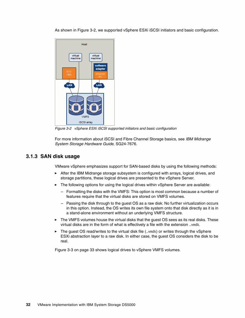
As shown in Figure 3-2, we supported vSphere ESXi iSCSI initiators and basic configuration.
Figure 3-2 vSphere ESXi iSCSI supported initiators and basic configuration
For more information about iSCSI and Fibre Channel Storage basics, see IBM Midrange System Storage Hardware Guide, SG24-7676.
3.1.3 SAN disk usage
VMware vSphere emphasizes support for SAN-based disks by using the following methods:
� After the IBM Midrange storage subsystem is configured with arrays, logical drives, and storage partitions, these logical drives are presented to the vSphere Server.
� The following options for using the logical drives within vSphere Server are available:
– Formatting the disks with the VMFS: This option is most common because a number of features require that the virtual disks are stored on VMFS volumes.
– Passing the disk through to the guest OS as a raw disk: No further virtualization occurs in this option. Instead, the OS writes its own file system onto that disk directly as it is in a stand-alone environment without an underlying VMFS structure.
� The VMFS volumes house the virtual disks that the guest OS sees as its real disks. These virtual disks are in the form of what is effectively a file with the extension .vmdk.
� The guest OS read/writes to the virtual disk file (.vmdk) or writes through the vSphere ESXi abstraction layer to a raw disk. In either case, the guest OS considers the disk to be real.
Figure 3-3 on page 33 shows logical drives to vSphere VMFS volumes.
32 VMware Implementation with IBM System Storage DS5000
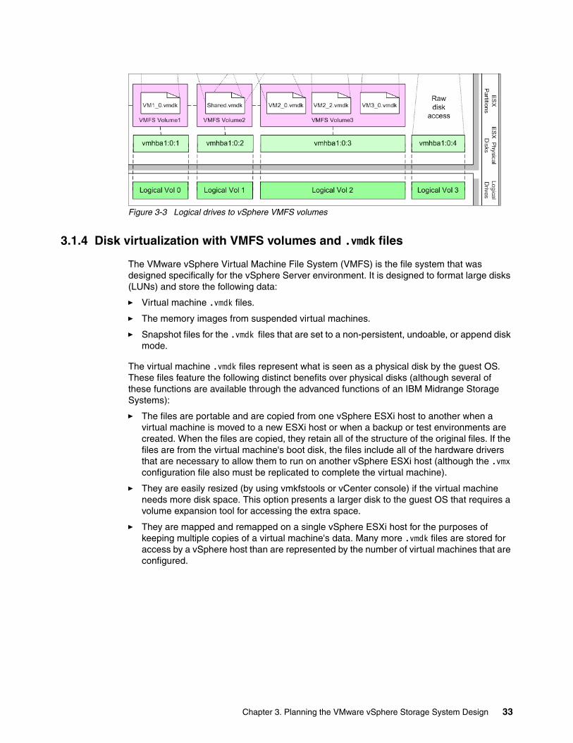
Figure 3-3 Logical drives to vSphere VMFS volumes
3.1.4 Disk virtualization with VMFS volumes and .vmdk files
The VMware vSphere Virtual Machine File System (VMFS) is the file system that was designed specifically for the vSphere Server environment. It is designed to format large disks (LUNs) and store the following data:
� Virtual machine .vmdk files.
� The memory images from suspended virtual machines.
� Snapshot files for the .vmdk files that are set to a non-persistent, undoable, or append disk mode.
The virtual machine .vmdk files represent what is seen as a physical disk by the guest OS. These files feature the following distinct benefits over physical disks (although several of these functions are available through the advanced functions of an IBM Midrange Storage Systems):
� The files are portable and are copied from one vSphere ESXi host to another when a virtual machine is moved to a new ESXi host or when a backup or test environments are created. When the files are copied, they retain all of the structure of the original files. If the files are from the virtual machine's boot disk, the files include all of the hardware drivers that are necessary to allow them to run on another vSphere ESXi host (although the .vmx configuration file also must be replicated to complete the virtual machine).
� They are easily resized (by using vmkfstools or vCenter console) if the virtual machine needs more disk space. This option presents a larger disk to the guest OS that requires a volume expansion tool for accessing the extra space.
� They are mapped and remapped on a single vSphere ESXi host for the purposes of keeping multiple copies of a virtual machine's data. Many more .vmdk files are stored for access by a vSphere host than are represented by the number of virtual machines that are configured.
Chapter 3. Planning the VMware vSphere Storage System Design 33
3.1.5 VMFS access mode: Public mode
Public mode is the default mode for VMware ESXi Server and the only option for VMware ESX 3.x and later.
By using a public VMFS version 1 (VMFS-1) volume, multiple ESXi Server computers access the VMware ESXi Server file system if the VMFS volume is on a shared storage system (for example, a VMFS on a storage area network). However, only one ESXi Server accesses the VMFS volume at a time.
By using a public VMFS version 2 (VMFS-2) volume, multiple ESXi Server computers access the VMware ESXi Server file system concurrently. VMware ESXi Server file systems that use a public mode include automatic locking to ensure file system consistency.
VMFS-3 partitions also allow multiple vSphere Servers to access the VMFS volume concurrently and use file locking to prevent contention on the .vmdk files.
Introduced with vSphere5, VMFS-5 provides the same file locking mechanism similar to VMFS-3 to prevent the contention on the .vmdk files.
3.1.6 vSphere Server .vmdk modes
Server management user interface is seen when the .vmdk files are created or after by editing an individual virtual machine's settings. vSphere Server features the following modes of operation for .vmdk file disks that are set from within the vSphere ESXi:
Persistent This mode is similar to normal physical disks in a server. vSphere Server writes immediately to a persistent disk.
Non-persistent Changes that were made since the last time a virtual machine was powered on are lost when that VM is powered off (soft reboots do not count as being powered off).
3.1.7 Specifics of using SAN Arrays with vSphere ESXi Server
The use of a SAN with an vSphere ESXi Server host differs from traditional SAN usage in various ways, which we discuss in this section.
Sharing a VMFS across vSphere ESXi ServersvSphere Virtual Machine File System, which is shown in Figure 3-4 on page 35, is designed for concurrent access from multiple physical machines and enforces the appropriate access controls on virtual machine files.
vSphere VMFS perform the following tasks:
� Coordinate access to virtual disk files: ESXi Server uses file level locks, which the VMFS distributed lock manager manages. This feature prevents the same virtual machine from being powered on by multiple servers at the same time.
� Coordinate access to VMFS internal file system information (metadata): vSphere ESXi Server by character coordinates accurate shared data.
Important: Starting with VMFS-3, a shared mode is not available. The clustering occurs with raw device mapping (RDM) in physical or virtual compatibility mode.
34 VMware Implementation with IBM System Storage DS5000
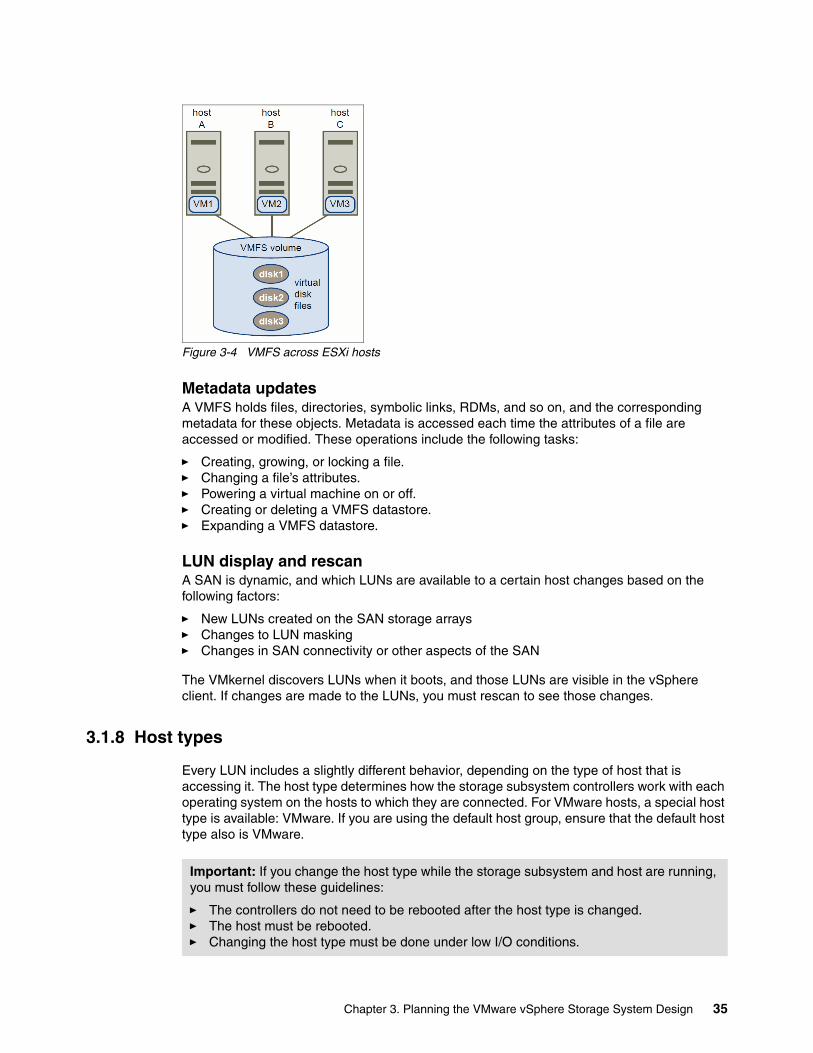
Figure 3-4 VMFS across ESXi hosts
Metadata updatesA VMFS holds files, directories, symbolic links, RDMs, and so on, and the corresponding metadata for these objects. Metadata is accessed each time the attributes of a file are accessed or modified. These operations include the following tasks:
� Creating, growing, or locking a file.� Changing a file’s attributes.� Powering a virtual machine on or off.� Creating or deleting a VMFS datastore.� Expanding a VMFS datastore.
LUN display and rescanA SAN is dynamic, and which LUNs are available to a certain host changes based on the following factors:
� New LUNs created on the SAN storage arrays� Changes to LUN masking� Changes in SAN connectivity or other aspects of the SAN
The VMkernel discovers LUNs when it boots, and those LUNs are visible in the vSphere client. If changes are made to the LUNs, you must rescan to see those changes.
3.1.8 Host types
Every LUN includes a slightly different behavior, depending on the type of host that is accessing it. The host type determines how the storage subsystem controllers work with each operating system on the hosts to which they are connected. For VMware hosts, a special host type is available: VMware. If you are using the default host group, ensure that the default host type also is VMware.
Important: If you change the host type while the storage subsystem and host are running, you must follow these guidelines:
� The controllers do not need to be rebooted after the host type is changed. � The host must be rebooted.� Changing the host type must be done under low I/O conditions.
Chapter 3. Planning the VMware vSphere Storage System Design 35
3.1.9 Levels of indirection
If you often work with traditional SANs, the levels of indirection might be confusing for the following reasons:
� You cannot directly access the virtual machine operating system that uses the storage. With traditional tools, you monitor only the VMware ESXi Server operating system, but not the virtual machine operating system. You use the vSphere Client to monitor virtual machines.
� By default, each virtual machine is configured with one virtual hard disk and one virtual SCSI controller during the installation. You modify the SCSI controller type and SCSI bus sharing characteristics by using the vSphere Client to edit the virtual machine settings. You also add hard disks to your virtual machine.
� The HBA that is visible to the SAN administration tools is part of the VMware vSphere ESXi Server, not the virtual machine.
� The VMware vSphere ESXi Server system multipaths for you. The VMkernel multipathing plug-in that ESXi provides, by default, is the VMware Native Multipathing Plug-in (NMP). The NMP is an extensible module that performs the following tasks:
– Manages physical path claiming and unclaiming– Registers and un-registers logical devices– Associates physical paths with logical devices– Processes I/O requests to logical devices– Supports management tasks, such as abort or reset of logical devices
3.2 Deciding which IBM Midrange Storage Subsystem to use
Unfortunately, there is no one answer to the question of which IBM Midrange Storage Subsystem must be used in a VMware implementation. All of the IBM Midrange Storage Systems provide excellent functionality for attaching to VMware vSphere Servers. The answers depend on the specific requirements necessary for a vSphere Server and the expectations that must be met in terms of performance, availability, capacity, and so on.
Although there are many variables to consider, the sizing requirements for capacity and performance do not change when a vSphere Server is being considered instead of a group of individual physical servers. Some consolidation of SAN requirements might be achieved, but other requirements remain, for example, because of under-utilization, great consolidation is often possible with regards to the number of physical HBAs that are required. Therefore, the number of SAN switch ports that also are required for connection of those HBAs is affected. Because these items come at a considerable cost, any reduction in the number that is required represents significant savings. It is also common to find low-bandwidth usage of HBAs and SAN switch ports in a non-consolidated environment, thus also adding to the potential for consolidation of these items.
It is common that individual physical disk usage is high, and therefore reducing the number of physical disks often is not appropriate. As with all SAN implementations, consider the immediate requirement of the project and the possibilities for reasonable future growth.
36 VMware Implementation with IBM System Storage DS5000
3.3 Overview of IBM Midrange Storage Systems
In this section, we provide a brief overview of the IBM Midrange Storage Systems to help you decide which storage subsystem is best suited for your VMware environment. For more information about IBM Midrange Storage Systems, see the IBM Midrange System Storage Hardware Guide, SG24-7676.
3.3.1 Positioning the IBM Midrange Storage Systems
IBM Data Studio storage family is suitable for a broad range of business needs. From entry-level IBM System Storage DS3000 series, midrange IBM System Storage DS5000 series, to high-performance IBM System Storage DS8000® series, IBM Data Studio storage family meets the needs of small businesses and the requirements of large enterprises.
The IBM Midrange Storage Systems, also referred to as the IBM System Storage DS5000 series, are designed to meet the demanding open-systems requirements of today and tomorrow. They also establish a new standard for lifecycle longevity with field-replaceable host interface cards. Seventh-generation architecture delivers relentless performance, real reliability, multidimensional scalability, and unprecedented investment protection.
IBM System Storage DS5000 series consists of the following storage systems:
� DS5020 Express Disk System (1814-20A)
This system is targeted at growing midrange sites that require reliability, efficiency, and performance value.
� DS5100 Disk System (1818-51A)
This system is targeted at cost-conscious midrange sites that require high-end functionality and pay-as-you grow scalability.
� DS5300 Disk System (1818-53A)
This system is targeted at environments with compute-intensive applications and large-scale virtualization / consolidation implementations.
Figure 3-5 on page 38 shows the positioning of the products within the Midrange DS5000 series.
Chapter 3. Planning the VMware vSphere Storage System Design 37
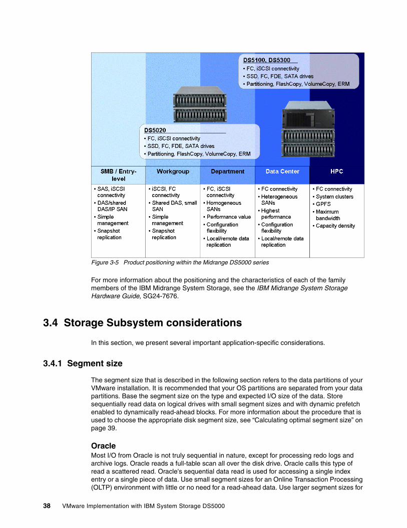
Figure 3-5 Product positioning within the Midrange DS5000 series
For more information about the positioning and the characteristics of each of the family members of the IBM Midrange System Storage, see the IBM Midrange System Storage Hardware Guide, SG24-7676.
3.4 Storage Subsystem considerations
In this section, we present several important application-specific considerations.
3.4.1 Segment size
The segment size that is described in the following section refers to the data partitions of your VMware installation. It is recommended that your OS partitions are separated from your data partitions. Base the segment size on the type and expected I/O size of the data. Store sequentially read data on logical drives with small segment sizes and with dynamic prefetch enabled to dynamically read-ahead blocks. For more information about the procedure that is used to choose the appropriate disk segment size, see “Calculating optimal segment size” on page 39.
OracleMost I/O from Oracle is not truly sequential in nature, except for processing redo logs and archive logs. Oracle reads a full-table scan all over the disk drive. Oracle calls this type of read a scattered read. Oracle's sequential data read is used for accessing a single index entry or a single piece of data. Use small segment sizes for an Online Transaction Processing (OLTP) environment with little or no need for a read-ahead data. Use larger segment sizes for
38 VMware Implementation with IBM System Storage DS5000
a Decision Support System (DSS) environment on which you are running full table scans through a data warehouse.
Remember the following important pints when block size is considered:
� Set the database block size lower than or equal to the disk drive segment size. If the segment size is set at 2 KB and the database block size is set at 4 KB, this procedure takes two I/O operations to fill the block, which results in performance degradation.
� Make sure that the segment size is an even multiple of the database block size. This practice prevents partial I/O operations from filling the block.
� Set the parameter db_file_multiblock_read_count appropriately. Normally, you want to set the db_file_multiblock_read_count as shown in the following example:
segment size = db_file_multiblock_read_count * DB_BLOCK_SIZE
You also set the db_file_multiblock_read_count so that the result of the previous calculation is smaller but in even multiples of the segment size. For example, if you have a segment size of 64 KB and a block size of 8 KB, you set the db_file_multiblock_read_count to four, which equals a value of 32 KB, which is an even multiple of the 64 KB-segment size.
SQL ServerFor SQL Server, the page size is fixed at 8 KB. SQL Server uses an extent size of 64 KB (eight 8-KB contiguous pages). For this reason, set the segment size to 64 KB. For more information, see “Calculating optimal segment size” on page 39.
Exchange serverSet the segment size to 64 KB or multiples of 64. For more information, see “Calculating optimal segment size”.
Calculating optimal segment sizeThe IBM term segment size refers to the amount of data that is written to one disk drive in an array before it writes to the next disk drive in the array. For example, in a RAID5 (4+1 array with a segment size of 128 KB), the first 128 KB of the LUN storage capacity is written to the first disk drive and the next 128 KB to the second disk drive. For a RAID1 2+2 array, 128 KB of an I/O is written to each of the two data disk drives and to the mirrors. If the I/O size is larger than the number of disk drives times 128 KB, this pattern repeats until the entire I/O is completed.
For large I/O requests, the optimal segment size for a RAID array is one that distributes a single host I/O across all data disk drives. The following formula for optimal segment size is used:
LUN segment size = LUN stripe width ÷ number of data disk drives
For RAID 5, the number of data disk drives is equal to the number of disk drives in the array minus 1, as shown in the following example:
RAID5, 4+1 with a 64 KB segment size => (5-1) * 64KB = 256 KB stripe width
For RAID 1, the number of data disk drives is equal to the number of disk drives divided by 2, as shown in the following example:
RAID 10, 2+2 with a 64 KB segment size => (2) * 64 KB = 128 KB stripe width
Chapter 3. Planning the VMware vSphere Storage System Design 39
For small I/O requests, the segment size must be large enough to minimize the number of segments (disk drives in the LUN) that must be accessed to satisfy the I/O request (minimize segment boundary crossings). For IOPS environments, set the segment size to 256 KB or larger so that the stripe width is at least as large as the median I/O size.
When you are using a logical drive manager to collect multiple storage system LUNs into a Logical Volume Manager (LVM) array (VG), the I/O stripe width is allocated across all of the segments of all of the data disk drives in all of the LUNs. The adjusted formula is shown in the following example:
LUN segment size = LVM I/O stripe width / (# of data disk drives/LUN * # of LUNs/VG)
For more information about the terminology that is used in this process, see the vendor documentation for the specific Logical Volume Manager.
3.4.2 DS5000 cache features
The following cache features are included in the IBM Midrange Storage Systems feature set (most notably in the DS5100 and DS5300 storage systems):
� Permanent cache backup
This feature provides a cache hold-up and de-staging mechanism to save cache and processor memory to a permanent device. This feature replaces the reliance on batteries that are found in older models to keep the cache alive when power is interrupted.
Disk drive cache features permanent data retention in a power outage. This function is accomplished by using USB flash drives. The batteries only power the controllers until data in the cache is written to the USB flash drives. When the storage subsystem is powered up, the contents are reloaded to cache and flushed to the logical drives.
When you turn off the storage subsystem, it does not shut down immediately. The storage subsystem writes the contents of cache to the USB flash drives before powering off. Depending on the amount of cache, the storage subsystem might take up to several minutes to actually power off. Cache upgrades in DS5100 and DS5300 include both DIMMs and USB modules.
� Dedicated write cache mirroring
When this feature is enabled, all cache is mirrored between the controllers. If a controller fails, write cache is not lost because the other controller mirrored the cache. When write cache mirroring is enabled, there is no impact to performance.
Best practice: For most implementations, set the segment size of VMware data partitions to 256 KB.
Note: When cache is upgraded, memory DIMMs must be upgraded together with USB flash drives.
40 VMware Implementation with IBM System Storage DS5000
3.4.3 Enabling cache settings
Always enable read cache. Enabling read cache allows the controllers to process data from the cache if it was read before and thus the read is faster. Data remains in the read cache until it is flushed.
Enable write cache to let the controllers acknowledge writes when the data reaches the cache instead of waiting for the data to be written to the physical media. For other storage systems, a trade-off exists between data integrity and speed. IBM DS5000 storage subsystems are designed to store data on both controller caches before they are acknowledged. To protect data integrity, cache mirroring must be enabled to permit dual controller cache writes.
Enable write-cache mirroring to prevent the cache from being lost if there is a controller failure.
Whether you need to prefetch cache depends on the type of data that is stored on the logical drives and how that data is accessed. If the data is accessed randomly (by way of table spaces and indexes), disable prefetch. Disabling prefetch prevents the controllers from reading ahead segments of data that most likely is not used, unless your logical drive segment size is smaller than the data read size requested. If you are using sequential data, cache prefetch might increase performance as the data is pre-stored in cache before it is read.
3.4.4 Aligning file system partitions
Align partitions to stripe width. Calculate stripe width by using the following formula:
segment_size / block_size * num_drives
In this formula, 4+1 RAID5 with 512-KB segment equals 512 KB / 512 Byte * 4 drives= 4096 Bytes.
3.4.5 Premium features
Premium features, such as FlashCopy and VolumeCopy, are available for the virtual drive and RDM device. For virtual drives, VMware includes tools that provide these functions. For RDM devices, the IBM Midrange Storage Subsystem provides the following premium features:
� FlashCopy and VolumeCopy� Enhanced Remote Mirroring� Storage Partitioning
3.4.6 Considering individual virtual machines
Before you design your array and logical drives, you must determine the primary goals of the configuration: performance, reliability, growth, manageability, or cost. Each goal has positive and negative aspects and trade-offs. After you determine which goals are best for your environment, follow the guidelines that are discussed in this chapter to implement those goals. To get the best performance from the IBM storage subsystem, you must know the I/O characteristics of the files that are to be placed on the storage system. After you know the I/O characteristics of the files, you set up a correct array and logical drive to service these files.
Chapter 3. Planning the VMware vSphere Storage System Design 41
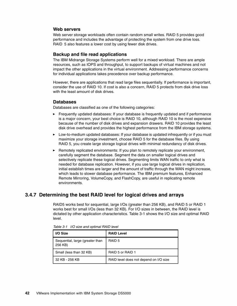
Web serversWeb server storage workloads often contain random small writes. RAID 5 provides good performance and includes the advantage of protecting the system from one drive loss. RAID 5 also features a lower cost by using fewer disk drives.
Backup and file read applicationsThe IBM Midrange Storage Systems perform well for a mixed workload. There are ample resources, such as IOPS and throughput, to support backups of virtual machines and not impact the other applications in the virtual environment. Addressing performance concerns for individual applications takes precedence over backup performance.
However, there are applications that read large files sequentially. If performance is important, consider the use of RAID 10. If cost is also a concern, RAID 5 protects from disk drive loss with the least amount of disk drives.
DatabasesDatabases are classified as one of the following categories:
� Frequently updated databases: If your database is frequently updated and if performance is a major concern, your best choice is RAID 10, although RAID 10 is the most expensive because of the number of disk drives and expansion drawers. RAID 10 provides the least disk drive overhead and provides the highest performance from the IBM storage systems.
� Low-to-medium updated databases: If your database is updated infrequently or if you must maximize your storage investment, choose RAID 5 for the database files. By using RAID 5, you create large storage logical drives with minimal redundancy of disk drives.
� Remotely replicated environments: If you plan to remotely replicate your environment, carefully segment the database. Segment the data on smaller logical drives and selectively replicate these logical drives. Segmenting limits WAN traffic to only what is needed for database replication. However, if you use large logical drives in replication, initial establish times are larger and the amount of traffic through the WAN might increase, which leads to slower database performance. The IBM premium features, Enhanced Remote Mirroring, VolumeCopy, and FlashCopy, are useful in replicating remote environments.
3.4.7 Determining the best RAID level for logical drives and arrays
RAID5 works best for sequential, large I/Os (greater than 256 KB), and RAID 5 or RAID 1 works best for small I/Os (less than 32 KB). For I/O sizes in between, the RAID level is dictated by other application characteristics. Table 3-1 shows the I/O size and optimal RAID level.
Table 3-1 I/O size and optimal RAID level
I/O Size RAID Level
Sequential, large (greater than 256 KB)
RAID 5
Small (less than 32 KB) RAID 5 or RAID 1
32 KB - 256 KB RAID level does not depend on I/O size
42 VMware Implementation with IBM System Storage DS5000
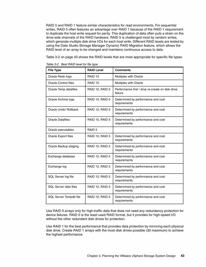
RAID 5 and RAID 1 feature similar characteristics for read environments. For sequential writes, RAID 5 often features an advantage over RAID 1 because of the RAID 1 requirement to duplicate the host write request for parity. This duplication of data often puts a strain on the drive-side channels of the RAID hardware. RAID 5 is challenged most by random writes, which generate multiple disk drive I/Os for each host write. Different RAID levels are tested by using the Data Studio Storage Manager Dynamic RAID Migration feature, which allows the RAID level of an array to be changed and maintains continuous access to data.
Table 3-2 on page 43 shows the RAID levels that are most appropriate for specific file types.
Table 3-2 Best RAID level for file type
Use RAID 0 arrays only for high-traffic data that does not need any redundancy protection for device failures. RAID 0 is the least-used RAID format, but it provides for high-speed I/O without the other redundant disk drives for protection.
Use RAID 1 for the best performance that provides data protection by mirroring each physical disk drive. Create RAID 1 arrays with the most disk drives possible (30 maximum) to achieve the highest performance.
File Type RAID Level Comments
Oracle Redo logs RAID 10 Multiplex with Oracle
Oracle Control files RAID 10 Multiplex with Oracle
Oracle Temp datafiles RAID 10, RAID 5 Performance first / drop re-create on disk drive failure
Oracle Archive logs RAID 10, RAID 5 Determined by performance and cost requirements
Oracle Undo/ Rollback RAID 10, RAID 5 Determined by performance and cost requirements
Oracle Datafiles RAID 10, RAID 5 Determined by performance and cost requirements
Oracle executables RAID 5
Oracle Export files RAID 10, RAID 5 Determined by performance and cost requirements
Oracle Backup staging RAID 10, RAID 5 Determined by performance and cost requirements
Exchange database RAID 10, RAID 5 Determined by performance and cost requirements
Exchange log RAID 10, RAID 5 Determined by performance and cost requirements
SQL Server log file RAID 10, RAID 5 Determined by performance and cost requirements
SQL Server data files RAID 10, RAID 5 Determined by performance and cost requirements
SQL Server Tempdb file RAID 10, RAID 5 Determined by performance and cost requirements
Chapter 3. Planning the VMware vSphere Storage System Design 43
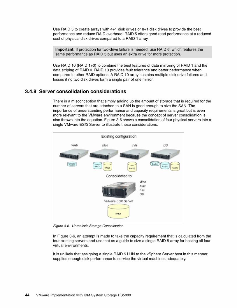
Use RAID 5 to create arrays with 4+1 disk drives or 8+1 disk drives to provide the best performance and reduce RAID overhead. RAID 5 offers good read performance at a reduced cost of physical disk drives compared to a RAID 1 array.
Use RAID 10 (RAID 1+0) to combine the best features of data mirroring of RAID 1 and the data striping of RAID 0. RAID 10 provides fault tolerance and better performance when compared to other RAID options. A RAID 10 array sustains multiple disk drive failures and losses if no two disk drives form a single pair of one mirror.
3.4.8 Server consolidation considerations
There is a misconception that simply adding up the amount of storage that is required for the number of servers that are attached to a SAN is good enough to size the SAN. The importance of understanding performance and capacity requirements is great but is even more relevant to the VMware environment because the concept of server consolidation is also thrown into the equation. Figure 3-6 shows a consolidation of four physical servers into a single VMware ESXi Server to illustrate these considerations.
Figure 3-6 Unrealistic Storage Consolidation
In Figure 3-6, an attempt is made to take the capacity requirement that is calculated from the four existing servers and use that as a guide to size a single RAID 5 array for hosting all four virtual environments.
It is unlikely that assigning a single RAID 5 LUN to the vSphere Server host in this manner supplies enough disk performance to service the virtual machines adequately.
Important: If protection for two-drive failure is needed, use RAID 6, which features the same performance as RAID 5 but uses an extra drive for more protection.
44 VMware Implementation with IBM System Storage DS5000
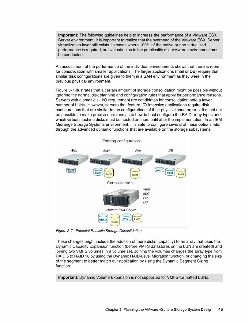
An assessment of the performance of the individual environments shows that there is room for consolidation with smaller applications. The larger applications (mail or DB) require that similar disk configurations are given to them in a SAN environment as they were in the previous physical environment.
Figure 3-7 illustrates that a certain amount of storage consolidation might be possible without ignoring the normal disk planning and configuration rules that apply for performance reasons. Servers with a small disk I/O requirement are candidates for consolidation onto a fewer number of LUNs. However, servers that feature I/O-intensive applications require disk configurations that are similar to the configurations of their physical counterparts. It might not be possible to make precise decisions as to how to best configure the RAID array types and which virtual machine disks must be hosted on them until after the implementation. In an IBM Midrange Storage Systems environment, it is safe to configure several of these options later through the advanced dynamic functions that are available on the storage subsystems.
Figure 3-7 Potential Realistic Storage Consolidation
These changes might include the addition of more disks (capacity) to an array that uses the Dynamic Capacity Expansion function (before VMFS datastores on the LUN are created) and joining two VMFS volumes in a volume set. Joining the volumes changes the array type from RAID 5 to RAID 10 by using the Dynamic RAID-Level Migration function, or changing the size of the segment to better match our application by using the Dynamic Segment Sizing function.
Important: The following guidelines help to increase the performance of a VMware ESXi Server environment. It is important to realize that the overhead of the VMware ESXi Server virtualization layer still exists. In cases where 100% of the native or non-virtualized performance is required, an evaluation as to the practicality of a VMware environment must be conducted.
Important: Dynamic Volume Expansion is not supported for VMFS-formatted LUNs.
Chapter 3. Planning the VMware vSphere Storage System Design 45
3.4.9 VMware ESXi Server Storage configurations
There are many ways to implement VMware ESXi Servers that are attached to IBM Midrange Storage Systems. Variants range from the number of HBAs/switches/paths that are available for a VMware ESXi Server, to multiple VMware ESXi Servers that share access to logical drives on the IBM Midrange Storage Systems.
Configuration planning that is done according to a common base of settings allows for growth from one configuration to another with minimal impact. It is recommended that all of the configurations are reviewed with your growth plan in mind (as much as possible) so that best practices are applied from the initial installation and last through a final configuration as it develops over time.
This principle correlates with the installation and configuration details that we give throughout this paper. The settings that must be made are compiled into a common set for all of configurations with other minimal changes listed for specific configurations as required.
At the time of writing, Data Studio Storage Manager software is not available for VMware ESXi Server operating systems. Therefore, to manage DS5000 Storage Subsystems with your VMware ESXi Server host, you must install the Storage Manager client software (SMclient) on a Windows or Linux management workstation. This workstation is the same that you use for the browser-based VMware ESXi Server Management interface.
VMware ESXi Server restrictionsThe following storage restrictions are common for VMware ESXi server:
SAN and connectivity restrictionsIn this section, we describe the following SAN and connectivity restrictions for storage:
� VMware ESXi Server hosts support host-agent (out-of-band) managed DS5000 configurations only. Direct-attach (in-band) managed configurations are not supported.
� VMware ESXi Server hosts support multiple host bus adapters (HBAs) and DS5000 devices. However, there is a restriction on the number of HBAs that are connected to a single DS5000 Storage Subsystem. You configure up to two HBAs per partition and up to two partitions per DS5000 Storage Subsystem. Other HBAs are added for more DS5000 Storage Subsystems and other SAN devices, up to the limits of your specific subsystem platform.
� When you use two HBAs in one VMware ESXi Server, LUN numbers must be the same for each HBA that is attached to the DS5000 Storage Subsystem.
� Single HBA configurations are allowed, but each single HBA configuration requires that both controllers in the DS5000 are connected to the HBA through a switch. If they are connected through a switch, both controllers must be within the same SAN zone as the HBA.
� Single-switch configurations are allowed, but each HBA and DS5000 controller combination must be in a separate SAN zone.
� Other storage devices, such as tape devices or other disk storage, must be connected through separate HBAs and SAN zones.
Important: A single HBA configuration leads to the loss of access data if a path fails.
46 VMware Implementation with IBM System Storage DS5000
Partitioning restrictionsIn this section, we describe the following partitioning restrictions for storage:
� The maximum number of partitions per VMware ESXi Server host, per DS5000 Storage Subsystem is two.
� All logical drives that are configured for VMware ESXi Server must be mapped to an VMware ESXi Server host group.
� Assign LUNs to the VMware ESXi Server starting with LUN number 0.
� Do not map an access (UTM) LUN (LUN id 31) to any of the VMware ESXi Server hosts or host groups. Access (UTM) LUNs are used only with in-band managed DS5000 configurations, which VMware ESXi Server does not support as of this writing.
Failover restrictionsIn this section, we describe the following failover restrictions for storage:
� You must use the VMware ESXi Server failover driver for multipath configurations. Other failover drivers, such as RDAC, are not supported in VMware ESXi Server configurations.
� The default failover policy for all DS5000 Storage Subsystems is now most recently used (MRU).
� Use the VMware host type in VMware ESXi Server configurations (2.0 and higher).
� The VMware host type automatically disables AVT/ADT.
Cross connect configuration for VMware vSphere ESXiA cross-connect Storage Area Network (SAN) configuration is required when VMware vSphere ESXi hosts are connected to IBM Midrange Storage Systems. Each HBA in a vSphere ESXi host must include a path to each of the controllers in the Data Studio storage subsystem. Figure 3-8 on page 48 shows the cross connections for VMware server configurations.
Important: Set the host type of all of your VMware ESXi Servers to VMware. If you are using the default host group, ensure that the default host type is VMware.
Dynamic Volume Expansion: Dynamic Volume Expansion is not supported for VMFS-formatted LUNs.
Recommendation: Do not boot your system from a SATA device.
Chapter 3. Planning the VMware vSphere Storage System Design 47
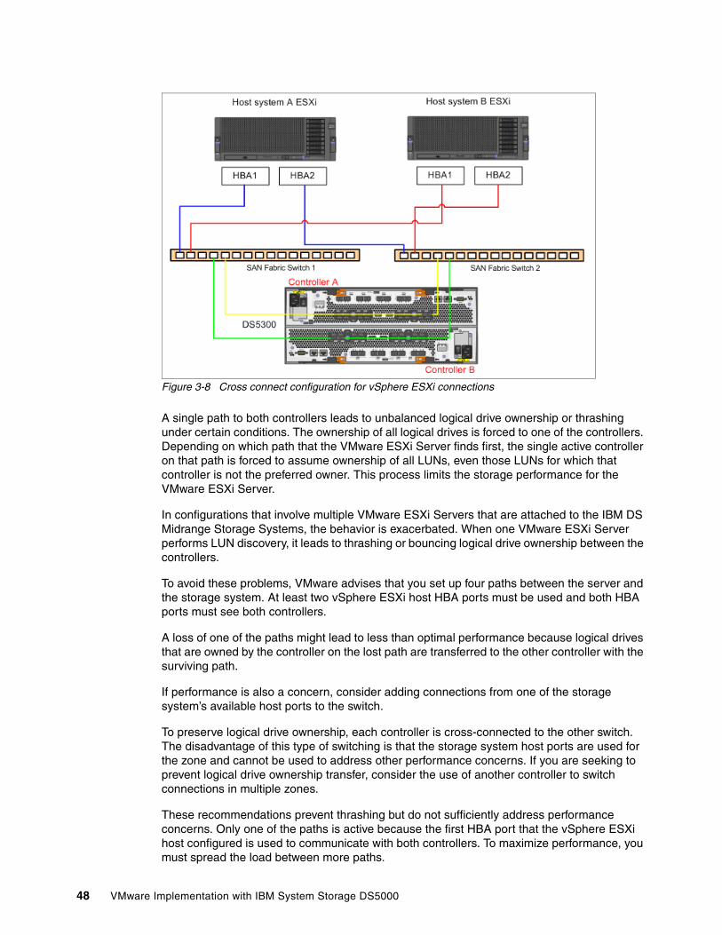
Figure 3-8 Cross connect configuration for vSphere ESXi connections
A single path to both controllers leads to unbalanced logical drive ownership or thrashing under certain conditions. The ownership of all logical drives is forced to one of the controllers. Depending on which path that the VMware ESXi Server finds first, the single active controller on that path is forced to assume ownership of all LUNs, even those LUNs for which that controller is not the preferred owner. This process limits the storage performance for the VMware ESXi Server.
In configurations that involve multiple VMware ESXi Servers that are attached to the IBM DS Midrange Storage Systems, the behavior is exacerbated. When one VMware ESXi Server performs LUN discovery, it leads to thrashing or bouncing logical drive ownership between the controllers.
To avoid these problems, VMware advises that you set up four paths between the server and the storage system. At least two vSphere ESXi host HBA ports must be used and both HBA ports must see both controllers.
A loss of one of the paths might lead to less than optimal performance because logical drives that are owned by the controller on the lost path are transferred to the other controller with the surviving path.
If performance is also a concern, consider adding connections from one of the storage system’s available host ports to the switch.
To preserve logical drive ownership, each controller is cross-connected to the other switch. The disadvantage of this type of switching is that the storage system host ports are used for the zone and cannot be used to address other performance concerns. If you are seeking to prevent logical drive ownership transfer, consider the use of another controller to switch connections in multiple zones.
These recommendations prevent thrashing but do not sufficiently address performance concerns. Only one of the paths is active because the first HBA port that the vSphere ESXi host configured is used to communicate with both controllers. To maximize performance, you must spread the load between more paths.
48 VMware Implementation with IBM System Storage DS5000
3.4.10 Configurations by function
In this section, we describe the different configurations that are available when multiple vSphere hosts are used.
A vSphere VMFS volume is set as one of the following states:
� A VMFS volume that is visible by only one vSphere ESXi host, which is called independent VMFS modules. When you have multiple vSphere ESXi hosts, independent VMFS modules are set through LUN masking (partitioning). This type of configuration is rarely needed and not recommended. It might be implemented when there is a requirement to keep separate the different vSphere hosts’ virtual machines. This requirement is necessary when two companies or departments share a SAN infrastructure but need to retain their own servers/applications.
� A VMFS volume that is visible by multiple vSphere ESXi hosts. This is the default. This VMFS mode is called public VMFS.
� A VMFS volume that is visible by multiple vSphere ESXi hosts and stores virtual disks (.vmdk) for split virtual clustering. This VMFS mode is called shared VMFS.
Public VMFS might be implemented for the following reasons:
� vSphere High availability (HA) that uses two (or more) vSphere ESXi hosts with shared LUNs allowing for one vSphere ESXi host to restart the workload of the other vSphere ESXi host, if needed. With public VMFS, virtual machines are run on any host, which ensures a level of application availability if there is hardware failure on one of the vSphere hosts.
This situation is possible, as multiple vSphere Servers access the same VMFS volumes and a virtual machine is started from potentially any vSphere Server host (although not simultaneously). It is important to understand that this approach does not protect against .vmdk file corruption or failures in the storage subsystem unless the .vmdk file is in a form replicated elsewhere.
� vSphere vMotion allows a running virtual machine to be migrated from one vSphere host to another without being taken offline. In scenarios where a vSphere Server must be taken down for maintenance, the virtual machines are moved without being shut down and they receive workload requests.
� vSphere Storage vMotion allows virtual machine disk files to be relocated between and across shared storage locations, which maintains continuous service availability.
� Clustering is another method to increase the availability of the environment and is only supported by VMware vSphere that uses Microsoft Clustering Services (MSCS) on Windows guests. Clustering transfers only the workload with minimal interruption during maintenance, but near continuous application availability is possible in the case of an OS crash or hardware failure, depending upon which of the following configurations are implemented:
– Local virtual machine cluster increases availability of the OS and application. Many server failures relate to software failure; therefore, implementing this configuration helps reduce software downtime. This configuration does not increase hardware availability, and this fact must be taken into account when the solution is designed.
– Split virtual machine cluster increases availability of the OS, application, and vSphere ESXi host hardware by splitting the cluster nodes across two vSphere ESXi hosts. If OS or vSphere ESXi host hardware fails, the application fails over to the surviving vSphere host or virtual machine cluster node.
Chapter 3. Planning the VMware vSphere Storage System Design 49
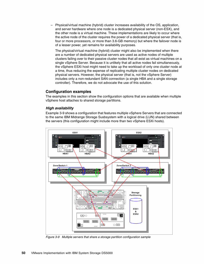
– Physical/virtual machine (hybrid) cluster increases availability of the OS, application, and server hardware where one node is a dedicated physical server (non-ESX), and the other node is a virtual machine. These implementations are likely to occur where the active node of the cluster requires the power of a dedicated physical server (that is, four or more processors, or more than 3.6-GB memory) but where the failover node is of a lesser power, yet remains for availability purposes.
The physical/virtual machine (hybrid) cluster might also be implemented when there are a number of dedicated physical servers are used as active nodes of multiple clusters failing over to their passive cluster nodes that all exist as virtual machines on a single vSphere Server. Because it is unlikely that all active nodes fail simultaneously, the vSphere ESXi host might need to take up the workload of only one cluster node at a time, thus reducing the expense of replicating multiple cluster nodes on dedicated physical servers. However, the physical server (that is, not the vSphere Server) includes only a non-redundant SAN connection (a single HBA and a single storage controller). Therefore, we do not advocate the use of this solution.
Configuration examplesThe examples in this section show the configuration options that are available when multiple vSphere host attaches to shared storage partitions.
High availability Example 3-9 shows a configuration that features multiple vSphere Servers that are connected to the same IBM Midrange Storage Susbsystem with a logical drive (LUN) shared between the servers (this configuration might include more than two vSphere ESXi hosts).
Figure 3-9 Multiple servers that share a storage partition configuration sample
50 VMware Implementation with IBM System Storage DS5000
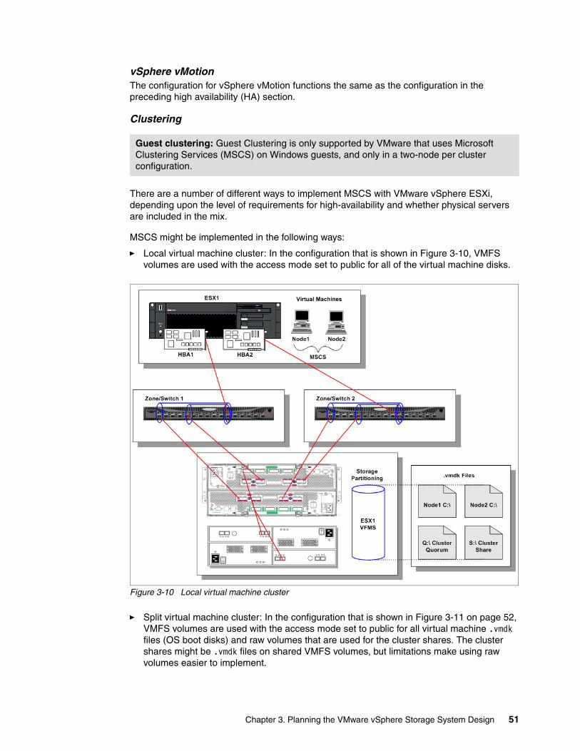
vSphere vMotionThe configuration for vSphere vMotion functions the same as the configuration in the preceding high availability (HA) section.
Clustering
There are a number of different ways to implement MSCS with VMware vSphere ESXi, depending upon the level of requirements for high-availability and whether physical servers are included in the mix.
MSCS might be implemented in the following ways:
� Local virtual machine cluster: In the configuration that is shown in Figure 3-10, VMFS volumes are used with the access mode set to public for all of the virtual machine disks.
Figure 3-10 Local virtual machine cluster
� Split virtual machine cluster: In the configuration that is shown in Figure 3-11 on page 52, VMFS volumes are used with the access mode set to public for all virtual machine .vmdk files (OS boot disks) and raw volumes that are used for the cluster shares. The cluster shares might be .vmdk files on shared VMFS volumes, but limitations make using raw volumes easier to implement.
Guest clustering: Guest Clustering is only supported by VMware that uses Microsoft Clustering Services (MSCS) on Windows guests, and only in a two-node per cluster configuration.
Chapter 3. Planning the VMware vSphere Storage System Design 51
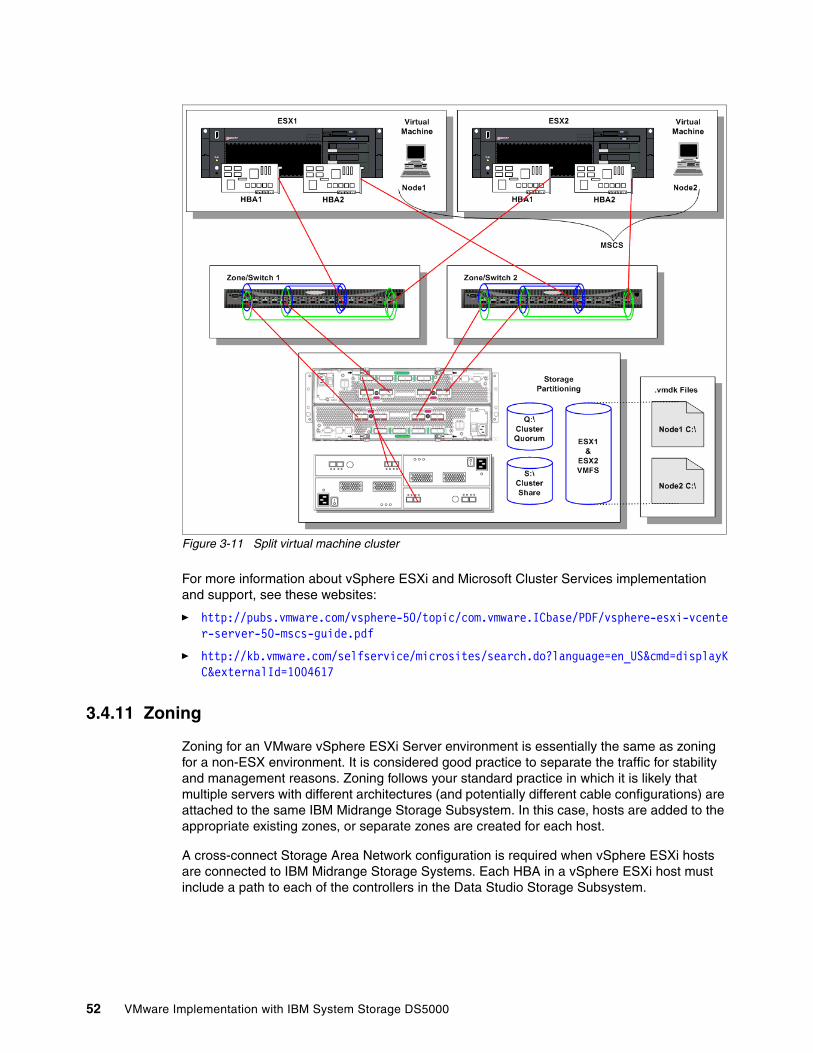
Figure 3-11 Split virtual machine cluster
For more information about vSphere ESXi and Microsoft Cluster Services implementation and support, see these websites:
� http://pubs.vmware.com/vsphere-50/topic/com.vmware.ICbase/PDF/vsphere-esxi-vcenter-server-50-mscs-guide.pdf
� http://kb.vmware.com/selfservice/microsites/search.do?language=en_US&cmd=displayKC&externalId=1004617
3.4.11 Zoning
Zoning for an VMware vSphere ESXi Server environment is essentially the same as zoning for a non-ESX environment. It is considered good practice to separate the traffic for stability and management reasons. Zoning follows your standard practice in which it is likely that multiple servers with different architectures (and potentially different cable configurations) are attached to the same IBM Midrange Storage Subsystem. In this case, hosts are added to the appropriate existing zones, or separate zones are created for each host.
A cross-connect Storage Area Network configuration is required when vSphere ESXi hosts are connected to IBM Midrange Storage Systems. Each HBA in a vSphere ESXi host must include a path to each of the controllers in the Data Studio Storage Subsystem.
52 VMware Implementation with IBM System Storage DS5000
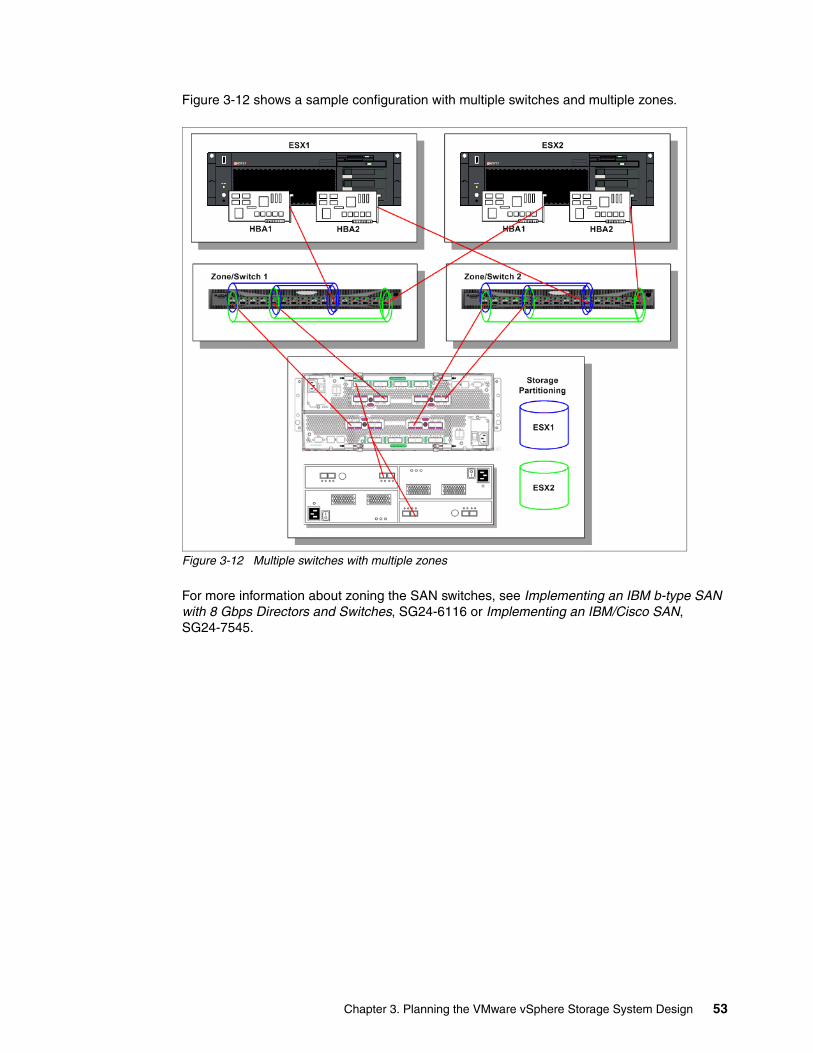
Figure 3-12 shows a sample configuration with multiple switches and multiple zones.
Figure 3-12 Multiple switches with multiple zones
For more information about zoning the SAN switches, see Implementing an IBM b-type SAN with 8 Gbps Directors and Switches, SG24-6116 or Implementing an IBM/Cisco SAN, SG24-7545.
Chapter 3. Planning the VMware vSphere Storage System Design 53

54 VMware Implementation with IBM System Storage DS5000

Chapter 4. Planning the VMware vSphere Server Design
Careful planning is essential to any new VMware vSphere installation. In this chapter, we provide guidelines to help you to plan your VMware vSphere environment.
4
© Copyright IBM Corp. 2012. All rights reserved. 55
4.1 Considering the VMware vSphere Server platform
The server platform contains the server hardware and the system software. The following issues must be considered when you are deciding on the hardware and operating system on which you want to run any application such as Oracle database:
� High availability: Is Oracle Real Application Clusters (Oracle RAC) needed at Guest OS Level to provide HA capabilities? Are other clustering solutions, such as Microsoft Clustering Services, required at Guest OS level (virtual machines)? Is vSphere DRS or vSphere vMotion needed to support high availability?
� Scalability: If the database is expected to grow and requires more hardware resources to provide future performance that the customer needs, Oracle provides a scalable approach to accommodate growth potential in Oracle databases, vSphere HA cluster, vSphere DRS, and vSphere Motion that accommodate scalability for virtual machines.
� Number of concurrent sessions: Determine the number of concurrent sessions and the complexity of these transactions before you decide the virtual hardware and operating system to use for the database.
� Amount of disk I/Os per second (IOPS): If the database is performing a large amount of IOPS, consider vSphere ESXi Server hardware that supports multiple HBAs. Also, consider the number of disk drive spindles that you must provide the necessary IOPS that are forecasted by the application.
� Size: If you have a small database or few users, a small-to-medium size hardware platform is justified.
� Cost: If cost is a factor for purchasing hardware, the x86 platform is a cheaper platform. The x86 provides outstanding performance for the money.
4.1.1 Minimum server requirements
For more information about and an updated list of the prerequisites for installing vSphere ESXi, see this website:
http://pubs.vmware.com/vsphere-50/topic/com.vmware.ICbase/PDF/vsphere-esxi-vcenter-server-50-installation-setup-guide.pdf
4.1.2 Maximum physical machine specifications
For more information about the maximum hardware capabilities of the vSphere ESXi, see this website:
http://www.vmware.com/pdf/vsphere5/r50/vsphere-50-configuration-maximums.pdf
56 VMware Implementation with IBM System Storage DS5000
4.1.3 Recommendations for enhanced performance
The following list outlines a basic configuration. In practice, you use multiple physical disks, which are SCSI disks, Fibre Channel LUNs, or RAID LUNs.
The following items are recommended for enhanced performance:
� A second disk controller with one or more drives that is dedicated to the VMs. The use of PVSCSI is an alternative for hardware or applications that drive a high amount of I/O throughput. For more information, see the Knowledge Base article at this website:
http://kb.vmware.com/selfservice/microsites/search.do?language=en_US&cmd=displayKC&externalId=1010398
� Sufficient RAM for each VM and the Support
� Dedicated Ethernet cards for network-sensitive VMs.
For best performance, all of the data that is used by the VMs must be on the physical disks that are allocated to VMs. Therefore, these physical disks must be large enough to hold disk images that are used by all of the VMs.
You also must provide enough RAM for all of the VMs and the Local Support Console-related services.
For more information about I/O device compatibility, see the VMware ESX Server I/O Adapter Compatibility Guide at this website:
http://partnerweb.vmware.com/comp_guide/pdf/vi_io_guide.pdf
You must ensure that enough free disk space is available to install the guest operating system and applications for each VM on the disk that they use.
For more information about general performance recommendations, see the updated Performance Best Practices document at this website:
http://www.vmware.com/pdf/Perf_Best_Practices_vSphere5.0.pdf
4.1.4 Considering the server hardware architecture
Available bandwidth depends on the server hardware. The number of buses adds to the aggregate bandwidth, but the number of HBAs sharing a single bus throttles the bandwidth.
Calculating aggregate bandwidthAn important limiting factor in I/O performance is the I/O capability of the server that hosts the application. The aggregate bandwidth of the server to the storage system is measured in MBps and contains the total capability of the buses to which the storage system is connected. For example, a 64-bit PCI bus that is clocked at 133 MHz includes a maximum bandwidth that is calculated by the following formula:
PCI Bus Throughput (MB/s) = PCI Bus Width / 8 * Bus Speed
64-bit /8 * 133 MHz = 1062 MB/s ~ = 1GB/s
Important: To ensure the best possible I/O performance and workload management, VMware vSphere ESXi provides its own drivers for supported devices. Be sure that the devices you plan to use in your server are supported.
Chapter 4. Planning the VMware vSphere Server Design 57
Table 4-1 shows PCI-X bus throughput.
Table 4-1 PCI-X bus throughput
Sharing bandwidth with multiple HBAsMultiple HBAs on a bus share a single source of I/O bandwidth. Each HBA might feature multiple FC ports, which often operate at 1 Gbps, 2 Gbps, 4 Gbps, or 8 Gbps. As a result, the ability to drive a storage system might be throttled by the server bus or the HBAs. Therefore, whenever you configure a server or analyze I/O performance, you must know that amount of server bandwidth that is available and which devices are sharing that bandwidth.
VMware vSphere ESXi path failover and load distributionvSphere ESXi includes a built-in failover driver to manage multiple paths that are called Native Multipath Plug-In (NMP). At startup, or during a rescan that might be issued from the vCenter Console, all LUNs or logical drives are detected. When multiple paths to a logical drive are found, the failover driver (or NMP) is configured and uses the default Most Recently Used (MRU) policy. The IBM Midrange Storage Subsystem is an Active/Passive storage system in which logical drive ownership is distributed between the two controllers. The individual logical drives are presented to the vSphere ESXi host by both controllers. The vSphere ESXi host configures both controllers as possible owners of a LUN, even though only one controller owns the LUN. ESXi host distinguishes between the active controller, the controller that owns a logical drive, and the passive controller. The active controller is the preferred controller.
The NMP failover driver provides the following policies or Path Selection Plug-Ins (PSPs):
� Fixed: The fixed policy is intended for Active/Active devices and is not recommended for the IBM Midrange Storage Systems. If the fixed policy is selected for logical drives that are presented by the IBM Midrange Storage Subsystem, thrashing might result.
� Most recent used (MRU): The MRU policy is intended for Active/Passive devices and is a requirement for configurations with IBM Midrange Storage Systems.
MHz PCI Bus Width Throughput (MB/s)
66 64 528
100 64 800
133 64 1064
266 64 2128
533 64 4264
Important: Additional multi-path drivers, such as RDAC, are not supported by vSphere ESXi.
Important: The use of active or passive arrays with a fixed path policy potentially leads to path thrashing. For more information about Active/Active and Active/Passive Disk Arrays and path thrashing, see the SAN System Design and Deployment Guide, at this website:
http://pubs.vmware.com/vsphere-50/topic/com.vmware.ICbase/PDF/vsphere-esxi-vcenter-server-50-storage-guide.pdf
58 VMware Implementation with IBM System Storage DS5000
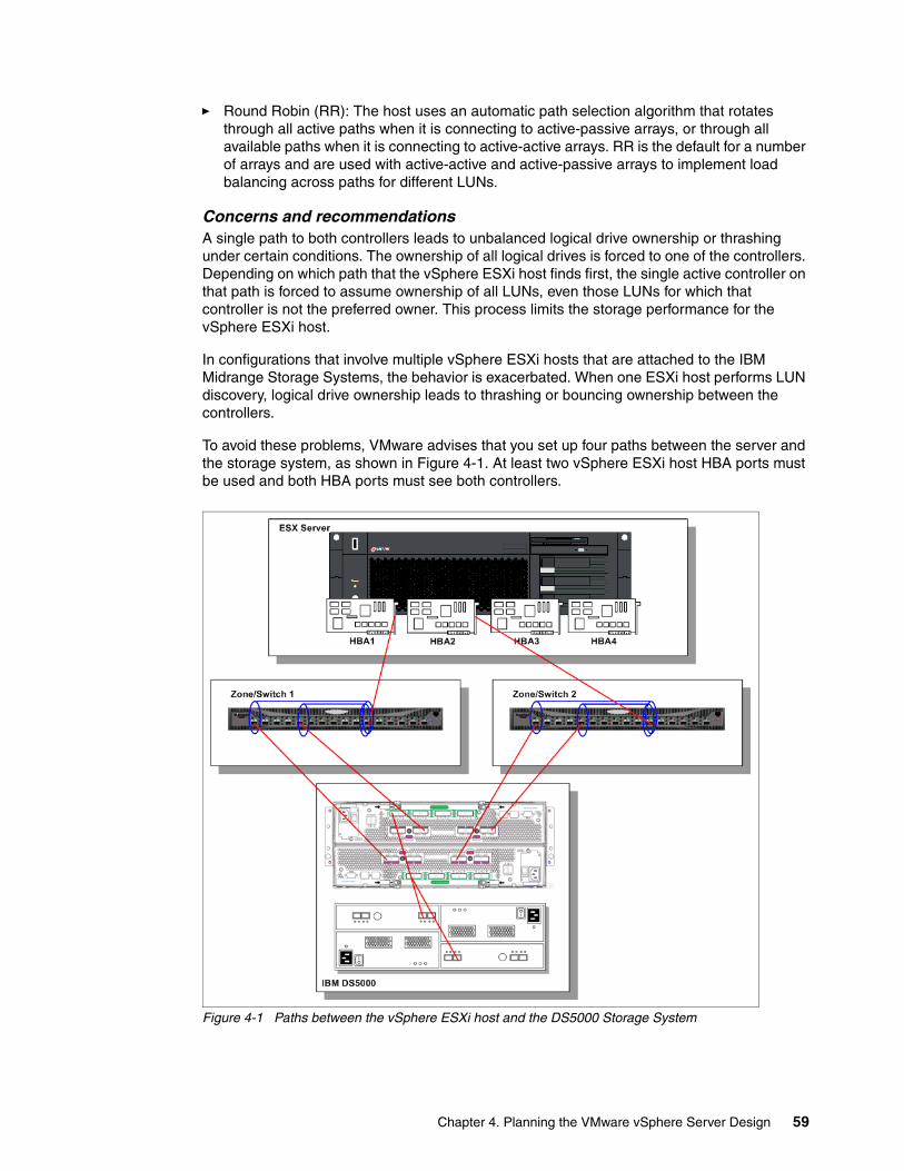
� Round Robin (RR): The host uses an automatic path selection algorithm that rotates through all active paths when it is connecting to active-passive arrays, or through all available paths when it is connecting to active-active arrays. RR is the default for a number of arrays and are used with active-active and active-passive arrays to implement load balancing across paths for different LUNs.
Concerns and recommendationsA single path to both controllers leads to unbalanced logical drive ownership or thrashing under certain conditions. The ownership of all logical drives is forced to one of the controllers. Depending on which path that the vSphere ESXi host finds first, the single active controller on that path is forced to assume ownership of all LUNs, even those LUNs for which that controller is not the preferred owner. This process limits the storage performance for the vSphere ESXi host.
In configurations that involve multiple vSphere ESXi hosts that are attached to the IBM Midrange Storage Systems, the behavior is exacerbated. When one ESXi host performs LUN discovery, logical drive ownership leads to thrashing or bouncing ownership between the controllers.
To avoid these problems, VMware advises that you set up four paths between the server and the storage system, as shown in Figure 4-1. At least two vSphere ESXi host HBA ports must be used and both HBA ports must see both controllers.
Figure 4-1 Paths between the vSphere ESXi host and the DS5000 Storage System
Chapter 4. Planning the VMware vSphere Server Design 59
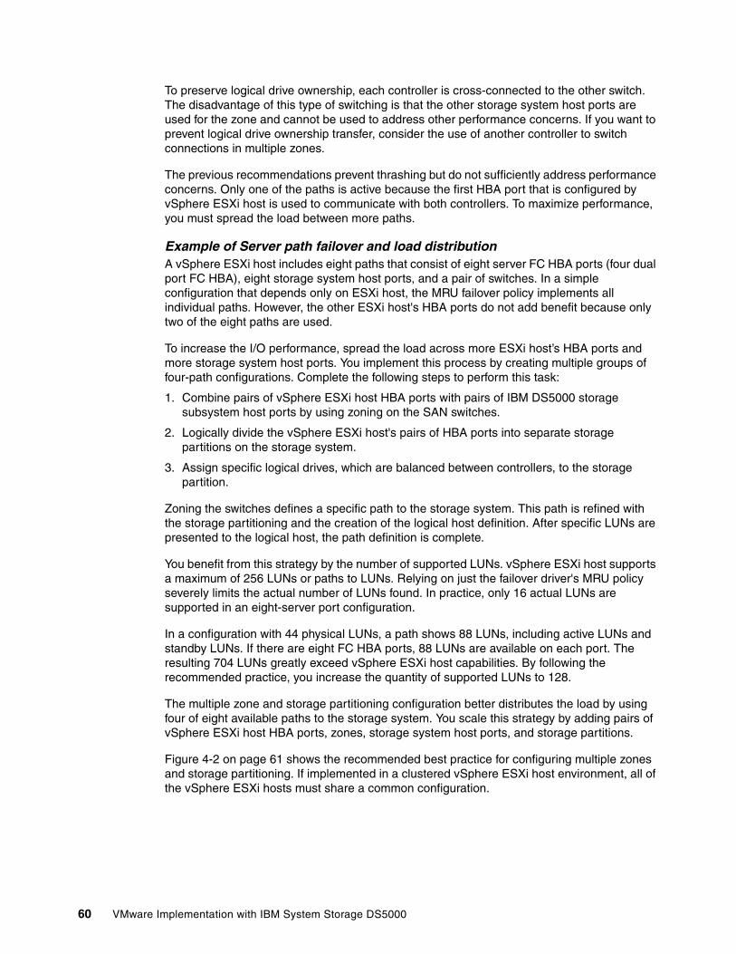
To preserve logical drive ownership, each controller is cross-connected to the other switch. The disadvantage of this type of switching is that the other storage system host ports are used for the zone and cannot be used to address other performance concerns. If you want to prevent logical drive ownership transfer, consider the use of another controller to switch connections in multiple zones.
The previous recommendations prevent thrashing but do not sufficiently address performance concerns. Only one of the paths is active because the first HBA port that is configured by vSphere ESXi host is used to communicate with both controllers. To maximize performance, you must spread the load between more paths.
Example of Server path failover and load distributionA vSphere ESXi host includes eight paths that consist of eight server FC HBA ports (four dual port FC HBA), eight storage system host ports, and a pair of switches. In a simple configuration that depends only on ESXi host, the MRU failover policy implements all individual paths. However, the other ESXi host's HBA ports do not add benefit because only two of the eight paths are used.
To increase the I/O performance, spread the load across more ESXi host’s HBA ports and more storage system host ports. You implement this process by creating multiple groups of four-path configurations. Complete the following steps to perform this task:
1. Combine pairs of vSphere ESXi host HBA ports with pairs of IBM DS5000 storage subsystem host ports by using zoning on the SAN switches.
2. Logically divide the vSphere ESXi host's pairs of HBA ports into separate storage partitions on the storage system.
3. Assign specific logical drives, which are balanced between controllers, to the storage partition.
Zoning the switches defines a specific path to the storage system. This path is refined with the storage partitioning and the creation of the logical host definition. After specific LUNs are presented to the logical host, the path definition is complete.
You benefit from this strategy by the number of supported LUNs. vSphere ESXi host supports a maximum of 256 LUNs or paths to LUNs. Relying on just the failover driver's MRU policy severely limits the actual number of LUNs found. In practice, only 16 actual LUNs are supported in an eight-server port configuration.
In a configuration with 44 physical LUNs, a path shows 88 LUNs, including active LUNs and standby LUNs. If there are eight FC HBA ports, 88 LUNs are available on each port. The resulting 704 LUNs greatly exceed vSphere ESXi host capabilities. By following the recommended practice, you increase the quantity of supported LUNs to 128.
The multiple zone and storage partitioning configuration better distributes the load by using four of eight available paths to the storage system. You scale this strategy by adding pairs of vSphere ESXi host HBA ports, zones, storage system host ports, and storage partitions.
Figure 4-2 on page 61 shows the recommended best practice for configuring multiple zones and storage partitioning. If implemented in a clustered vSphere ESXi host environment, all of the vSphere ESXi hosts must share a common configuration.
60 VMware Implementation with IBM System Storage DS5000
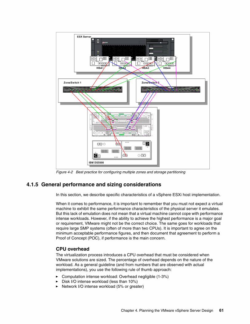
Figure 4-2 Best practice for configuring multiple zones and storage partitioning
4.1.5 General performance and sizing considerations
In this section, we describe specific characteristics of a vSphere ESXi host implementation.
When it comes to performance, it is important to remember that you must not expect a virtual machine to exhibit the same performance characteristics of the physical server it emulates. But this lack of emulation does not mean that a virtual machine cannot cope with performance intense workloads. However, if the ability to achieve the highest performance is a major goal or requirement, VMware might not be the correct choice. The same goes for workloads that require large SMP systems (often of more than two CPUs). It is important to agree on the minimum acceptable performance figures, and then document that agreement to perform a Proof of Concept (POC), if performance is the main concern.
CPU overheadThe virtualization process introduces a CPU overhead that must be considered when VMware solutions are sized. The percentage of overhead depends on the nature of the workload. As a general guideline (and from numbers that are observed with actual implementations), you use the following rule of thumb approach:
� Computation intense workload: Overhead negligible (1-3%)� Disk I/O intense workload (less than 10%)� Network I/O intense workload (5% or greater)
Chapter 4. Planning the VMware vSphere Server Design 61
In reality, you might see a mixed workload might result in an average overhead of 10%. Software iSCSI overhead also was reduced compared to previous versions of VMware ESX Server. ESXi 5.0 includes the following performance enhancements:
� 160 Logical CPUs and 2048 Virtual CPUs Per Host: ESXi 5.0 provides headroom for more virtual machines per host and the ability to achieve even higher consolidation ratios on larger machines that are considered Monster VMs.
� 64-bit VMkernel: The VMkernel, a core component of the ESXi hypervisor, is 64-bit version 4.0. This version provides greater host physical memory capacity and more seamless hardware support than earlier releases.
The vSphere ESXi scheduler includes the following features and enhancements that help improve the throughput of all workloads, with notable gains in I/O intensive workloads:
� Relaxed co-scheduling of vCPUs, introduced in earlier versions of VMware ESX Server, is further fine-tuned, especially for SMP VM’s.
� vSphere ESXi (4.0 and higher) scheduler uses newer, finer-grained locking that reduces scheduling overheads in cases where frequent scheduling decisions are needed.
� The new scheduler is aware of processor cache topology and accounts for the processor cache architecture to optimize CPU usage.
� For I/O intensive workloads, interrupt delivery and the associated processing costs make up a large component of the virtualization overhead. The scheduler enhancements greatly improve the efficiency of interrupt delivery and associated processing.
4.2 Operating system considerations
This section describes items to consider when a particular operating system is used and how that operating system affects partition alignments.
4.2.1 Buffering the I/O
The type of I/O (buffered or unbuffered) that is provided by the operating system to the application is an important factor in analyzing storage performance issues. Unbuffered I/O (also known as raw I/O or direct I/O) moves data directly between the application and the disk drive devices. Buffered I/O is a service that is provided by the operating system or by the file system. Buffering improves application performance by caching write data in a file system buffer, which the operating system or the file system periodically moves to permanent storage. Buffered I/O is generally preferred for shorter and more frequent transfers. File system buffering might change the I/O patterns that are generated by the application. Writes might coalesce so that the pattern that is seen by the storage system is more sequential and more write-intensive than the application I/O. Direct I/O is preferred for larger, less frequent transfers and for applications that provide their own extensive buffering (for example, Oracle). Regardless of I/O type, I/O performance generally improves when the storage system is kept busy with a steady supply of I/O requests from the host application. You must become familiar with the parameters that the operating system provides for controlling I/O (for example, maximum transfer size).
62 VMware Implementation with IBM System Storage DS5000
4.2.2 Aligning host I/O with RAID striping
For all file systems and operating system types, you must avoid performance degrading segment crossings. You must not let I/O span a segment boundary. Matching I/O size (commonly, by a power-of-two) to array layout helps maintain aligned I/O across the entire disk drive. However, this statement is true only if the starting sector is correctly aligned to a segment boundary. Segment crossing is often seen in the Windows operating system, and the manner in which the partition alignment works depends on the version of Windows that is used and the version in which the partition alignment was created. In Windows Server 2008, partition alignment is often performed by default. The default for disks larger than 4 GB is 1 MB; the setting is configurable and is found in the following registry:
HKLM\SYSTEM\CurrentControlSet\Services\VDS\Alignment
For partitions that are created by Windows 2000 or Windows 2003, start at the 64th sector. Starting at the 64th sector causes misalignment with the underlying RAID striping and allows the possibility for a single I/O operation to span multiple segments.
Because the alignment of file system partitions impacts performance, every new VMFS3 or VMFS5 partition is automatically aligned along the 1 MB boundary since vSphere ESXi 5.0. For VMFS3 partition that were created by using an earlier version of ESX/ESXi that aligned along the 64 KB boundary (and that file system is then upgraded to VMFS5), it retains its 64KB alignment and must be aligned manually.
4.2.3 Recommendations for host bus adapter settings
The following HBA guidelines are recommended:
� Use the default HBA settings of the HBA vendor.
� Use the same model of HBA in the vSphere ESXi host. Mixing HBAs from various vendors in the same vSphere ESXi host is not supported.
� Ensure that the Fibre Channel HBAs are installed in the correct slots on the host that is based on slot and bus speed. Balance PCI bus load among the available busses in the server.
� Make sure that each server includes enough HBAs to allow for maximum throughput for all the applications that are hosted on the server for the peak period. I/O spread across multiple HBAs provide higher throughput and less latency for each application.
� Make sure that the server is connected to a dual redundant fabric to provide redundancy in the event of HBA failure.
4.2.4 Recommendations for Fibre Channel Switch settings
The following Fibre Channel Switch settings are recommended:
� Enable In-Order Delivery: Recommended settings are available from the supplier of the storage system. For example, on Brocade switches, verify that the In-Order Delivery parameter is enabled.
� Inter-switch Links: In a multi-switch SAN fabric where I/O traverses inter-switch links, make sure to configure sufficient inter-switch link bandwidth.
� Disable Trunking on the Fibre Channel switch: When a Cisco Fibre Channel switch is used, the IBM Midrange Storage Subsystem host ports and the Fibre Channel HBA ports on the server cannot be configured on the switch with the trunking enabled. The use of the trunking feature causes thrashing of logical drive ownership on the storage system.
Chapter 4. Planning the VMware vSphere Server Design 63
Trunking is set to automatic by default. You change trunking to non-trunk under the Trunk Config tab.
4.2.5 Using Command Tag Queuing
Command Tag Queuing (CTQ) refers to the controller’s ability to line up multiple SCSI commands for a single LUN and run the commands in an optimized order that minimizes rotational and seek latencies. Although CTQ might not help in certain cases, such as single-threaded I/O, CTQ never affects performance and is generally recommended. The IBM models vary in CTQ capability, often up to 2048 per controller. Adjust the CTQ size to service multiple hosts. CTQ is enabled by default on IBM storage systems, but you also must enable CTQ on the host operating system and on the HBA. For more information, see the documentation from the HBA vendor.
The capability of a single host varies by the type of operating system, but you often calculate CTQ by using the following formula:
OS CTQ Depth Setting = Maximum OS queue depth (< 255) /Total # of LUNs
4.2.6 Analyzing I/O characteristics
Consider the following issues when you analyze the application to determine the best RAID level and the appropriate number of disk drives to put in each array:
� Is the I/O primarily sequential or random?
� Is the size of a typical I/O large (> 256 KB), small (< 64 KB), or in-between?
� If this size of the I/O is unknown, calculate a rough approximation of I/O size from the statistics that are reported by the IBM Data Studio Storage Manager Performance Monitor by using the following formula:
Current KB/second ÷ Current I/O/second = KB/I/O
� What is the I/O mix, that is, the proportion of reads to writes? Most environments are primarily Read.
� What read percent statistic does IBM DS Storage Manager Performance Monitor report?
� What type of I/O does the application use, buffered or unbuffered?
� Are concurrent I/Os or multiple I/O threads used?
In general, creating more sustained I/O produces the best overall results, up to the point of controller saturation. Write-intensive workloads are an exception to this rule.
Lower CTQ capacity: If the HBA features a lower CTQ capacity than the result of the CTQ calculation, the HBA’s CTQ capacity limits the actual setting.
64 VMware Implementation with IBM System Storage DS5000
4.2.7 Using VFMS for spanning across multiple LUNs
The following VFMS best practices are recommended:
� One VMFS volume is used per LUN and the VMFS volume must be carved up into many VMDKs. Although vSphere ESXi supports the use of several smaller LUNs for a single VMFS, spanning LUNs is not recommended. You improve performance by using a single, correctly sized LUN for the VMFS. Fewer larger LUNs are easier to manage.
� Separate heavy workloads must be separated onto LUNs as needed. You create several VMFS volumes to isolate I/O intensive VMs or use RDMs as an alternate way of isolating I/O intensive VMs to reduce contention.
� Mix VM’s with different peak access times.
For more information, see this website:
http://www.vmware.com/pdf/vmfs-best-practices-wp.pdf
Chapter 4. Planning the VMware vSphere Server Design 65

66 VMware Implementation with IBM System Storage DS5000
Part 2 Configuration
In part 2, we provide detailed steps for installing the VMware ESXi Server and storage-related set up and configuration.
Part 2
© Copyright IBM Corp. 2012. All rights reserved. 67

68 VMware Implementation with IBM System Storage DS5000
Chapter 5. VMware ESXi Server and Storage Configuration
In this chapter, we describe the process that is used for installing the VMware ESXi 5 Server and the configuration settings that are necessary to connect to DS5000 storage subsystems.
5
© Copyright IBM Corp. 2012. All rights reserved. 69
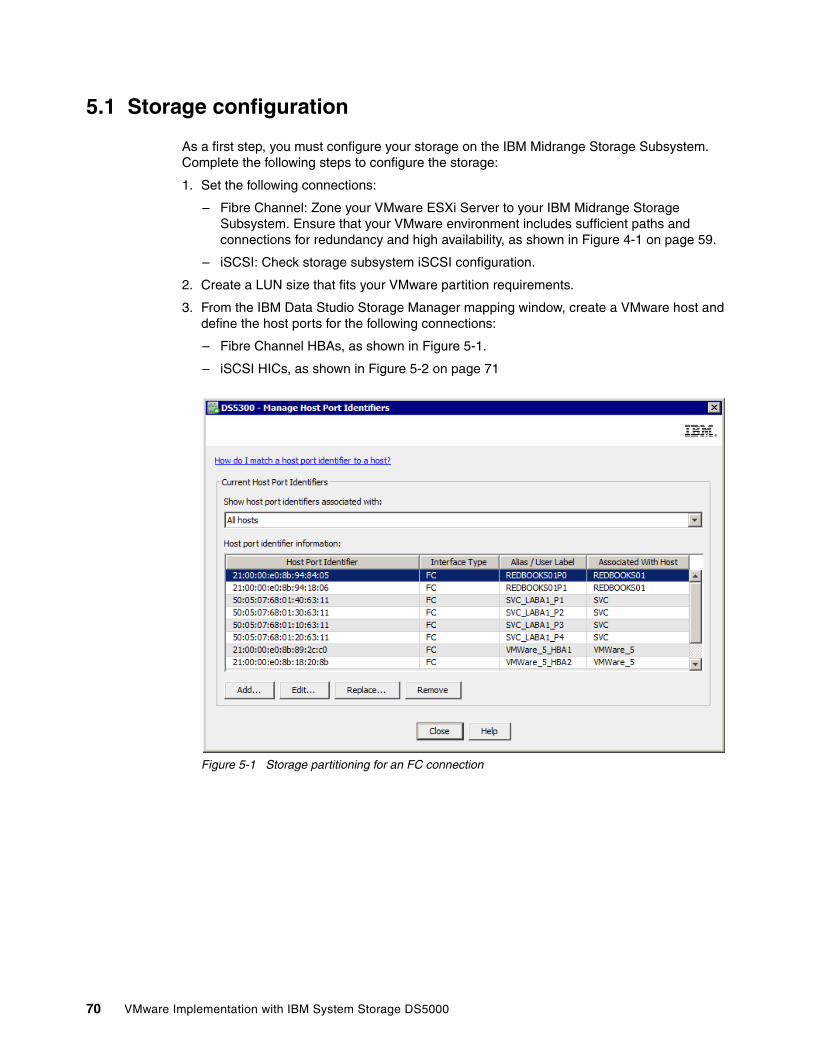
5.1 Storage configuration
As a first step, you must configure your storage on the IBM Midrange Storage Subsystem. Complete the following steps to configure the storage:
1. Set the following connections:
– Fibre Channel: Zone your VMware ESXi Server to your IBM Midrange Storage Subsystem. Ensure that your VMware environment includes sufficient paths and connections for redundancy and high availability, as shown in Figure 4-1 on page 59.
– iSCSI: Check storage subsystem iSCSI configuration.
2. Create a LUN size that fits your VMware partition requirements.
3. From the IBM Data Studio Storage Manager mapping window, create a VMware host and define the host ports for the following connections:
– Fibre Channel HBAs, as shown in Figure 5-1.
– iSCSI HICs, as shown in Figure 5-2 on page 71
Figure 5-1 Storage partitioning for an FC connection
70 VMware Implementation with IBM System Storage DS5000
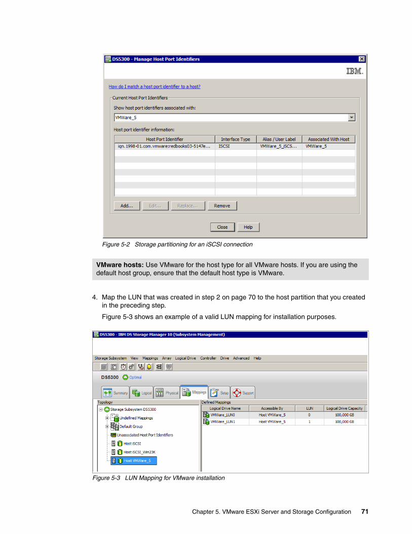
Figure 5-2 Storage partitioning for an iSCSI connection
4. Map the LUN that was created in step 2 on page 70 to the host partition that you created in the preceding step.
Figure 5-3 shows an example of a valid LUN mapping for installation purposes.
Figure 5-3 LUN Mapping for VMware installation
VMware hosts: Use VMware for the host type for all VMware hosts. If you are using the default host group, ensure that the default host type is VMware.
Chapter 5. VMware ESXi Server and Storage Configuration 71
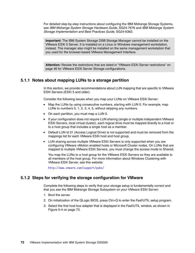
For detailed step-by-step instructions about configuring the IBM Midrange Storage Systems, see IBM Midrange System Storage Hardware Guide, SG24-7676 and IBM Midrange System Storage Implementation and Best Practices Guide, SG24-6363.
5.1.1 Notes about mapping LUNs to a storage partition
In this section, we provide recommendations about LUN mapping that are specific to VMware ESXi Servers (ESXi 5 and older).
Consider the following issues when you map your LUNs on VMware ESXi Server:
� Map the LUNs by using consecutive numbers, starting with LUN 0. For example, map LUNs to numbers 0, 1, 2, 3, 4, 5, without skipping any numbers.
� On each partition, you must map a LUN 0.
� If your configuration does not require LUN sharing (single or multiple independent VMware ESXi Servers, local virtual cluster), each logical drive must be mapped directly to a host or to a host group that includes a single host as a member.
� Default LUN id 31 (Access Logical Drive) is not supported and must be removed from the mappings list for each VMware ESXi host and host group.
� LUN sharing across multiple VMware ESXi Servers is only supported when you are configuring VMware vMotion enabled hosts or Microsoft Cluster nodes. On LUNs that are mapped to multiple VMware ESXi Servers, you must change the access mode to Shared.
You map the LUNs to a host group for the VMware ESXi Servers so they are available to all members of the host group. For more information about Windows Clustering with VMware ESXi Server, see this website:
http://www.vmware.com/support/pubs/
5.1.2 Steps for verifying the storage configuration for VMware
Complete the following steps to verify that your storage setup is fundamentally correct and that you see the IBM Midrange Storage Subsystem on your VMware ESXi Server:
1. Boot the server.
2. On initialization of the QLogic BIOS, press Ctrl+Q to enter the Fast!UTIL setup program.
3. Select the first host bus adapter that is displayed in the Fast!UTIL window, as shown in Figure 5-4 on page 73.
Important: The IBM System Storage DS® Storage Manager cannot be installed on the VMware ESXi 5 Server. It is installed on a Linux or Windows management workstation, instead. The manager also might be installed on the same management workstation that you used for the browser-based VMware Management Interface.
Attention: Review the restrictions that are listed in “VMware ESXi Server restrictions” on page 46 for VMware ESXi Server Storage configurations.
72 VMware Implementation with IBM System Storage DS5000
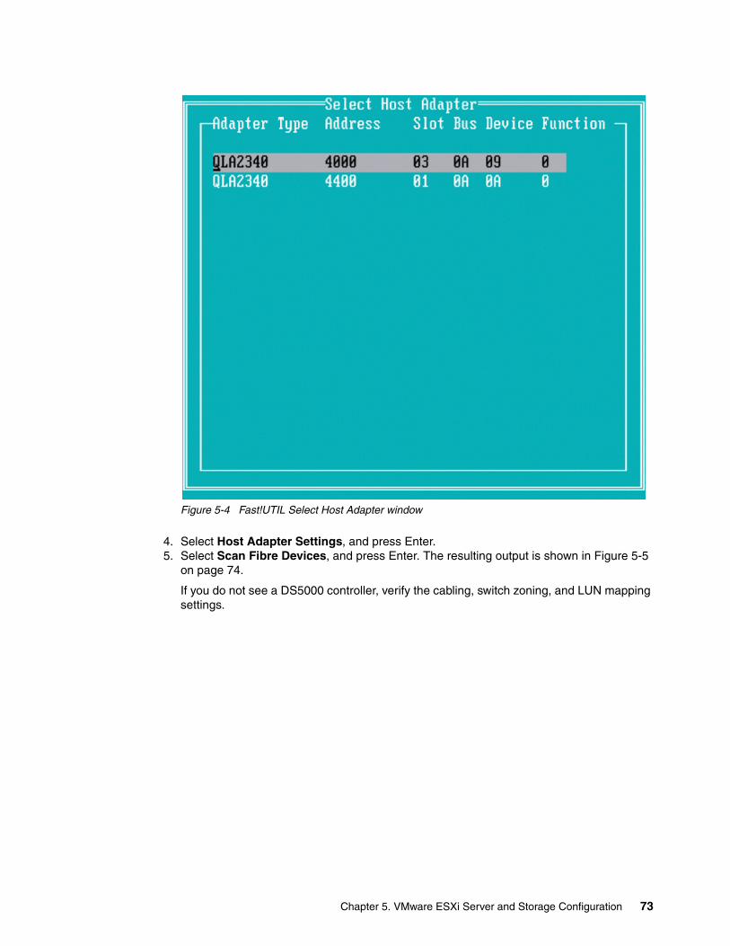
Figure 5-4 Fast!UTIL Select Host Adapter window
4. Select Host Adapter Settings, and press Enter.5. Select Scan Fibre Devices, and press Enter. The resulting output is shown in Figure 5-5
on page 74.
If you do not see a DS5000 controller, verify the cabling, switch zoning, and LUN mapping settings.
Chapter 5. VMware ESXi Server and Storage Configuration 73
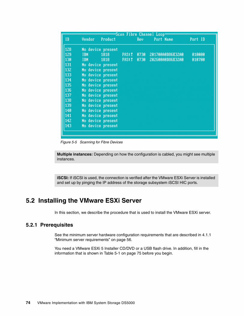
Figure 5-5 Scanning for Fibre Devices
5.2 Installing the VMware ESXi Server
In this section, we describe the procedure that is used to install the VMware ESXi server.
5.2.1 Prerequisites
See the minimum server hardware configuration requirements that are described in 4.1.1 “Minimum server requirements” on page 56.
You need a VMware ESXi 5 Installer CD/DVD or a USB flash drive. In addition, fill in the information that is shown in Table 5-1 on page 75 before you begin.
Multiple instances: Depending on how the configuration is cabled, you might see multiple instances.
iSCSI: If iSCSI is used, the connection is verified after the VMware ESXi Server is installed and set up by pinging the IP address of the storage subsystem iSCSI HIC ports.
74 VMware Implementation with IBM System Storage DS5000
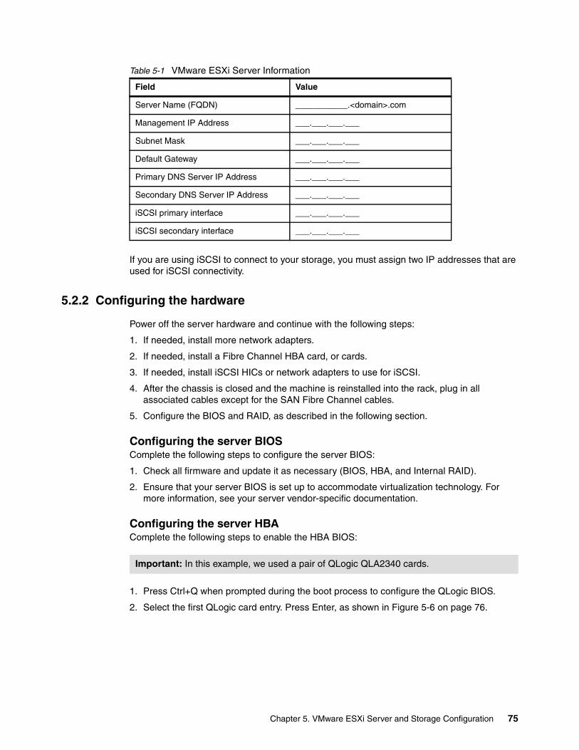
Table 5-1 VMware ESXi Server Information
If you are using iSCSI to connect to your storage, you must assign two IP addresses that are used for iSCSI connectivity.
5.2.2 Configuring the hardware
Power off the server hardware and continue with the following steps:
1. If needed, install more network adapters.
2. If needed, install a Fibre Channel HBA card, or cards.
3. If needed, install iSCSI HICs or network adapters to use for iSCSI.
4. After the chassis is closed and the machine is reinstalled into the rack, plug in all associated cables except for the SAN Fibre Channel cables.
5. Configure the BIOS and RAID, as described in the following section.
Configuring the server BIOSComplete the following steps to configure the server BIOS:
1. Check all firmware and update it as necessary (BIOS, HBA, and Internal RAID).
2. Ensure that your server BIOS is set up to accommodate virtualization technology. For more information, see your server vendor-specific documentation.
Configuring the server HBAComplete the following steps to enable the HBA BIOS:
1. Press Ctrl+Q when prompted during the boot process to configure the QLogic BIOS.
2. Select the first QLogic card entry. Press Enter, as shown in Figure 5-6 on page 76.
Field Value
Server Name (FQDN) ___________.<domain>.com
Management IP Address ___.___.___.___
Subnet Mask ___.___.___.___
Default Gateway ___.___.___.___
Primary DNS Server IP Address ___.___.___.___
Secondary DNS Server IP Address ___.___.___.___
iSCSI primary interface ___.___.___.___
iSCSI secondary interface ___.___.___.___
Important: In this example, we used a pair of QLogic QLA2340 cards.
Chapter 5. VMware ESXi Server and Storage Configuration 75
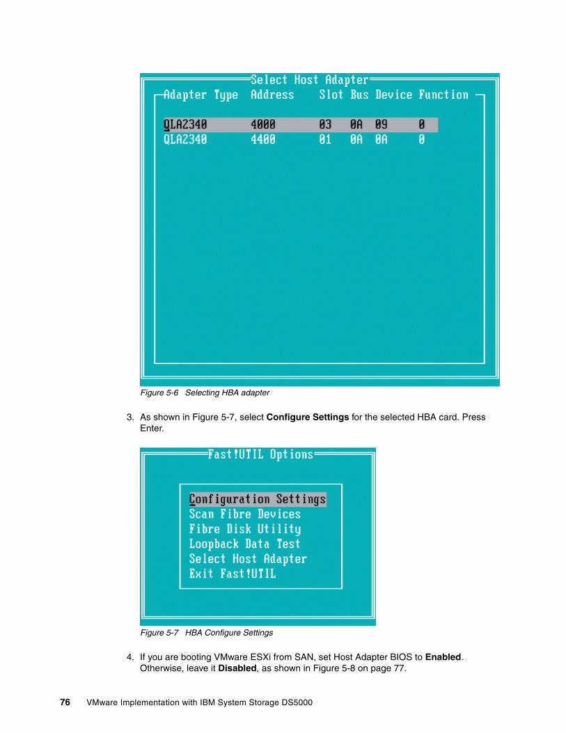
Figure 5-6 Selecting HBA adapter
3. As shown in Figure 5-7, select Configure Settings for the selected HBA card. Press Enter.
Figure 5-7 HBA Configure Settings
4. If you are booting VMware ESXi from SAN, set Host Adapter BIOS to Enabled. Otherwise, leave it Disabled, as shown in Figure 5-8 on page 77.
76 VMware Implementation with IBM System Storage DS5000
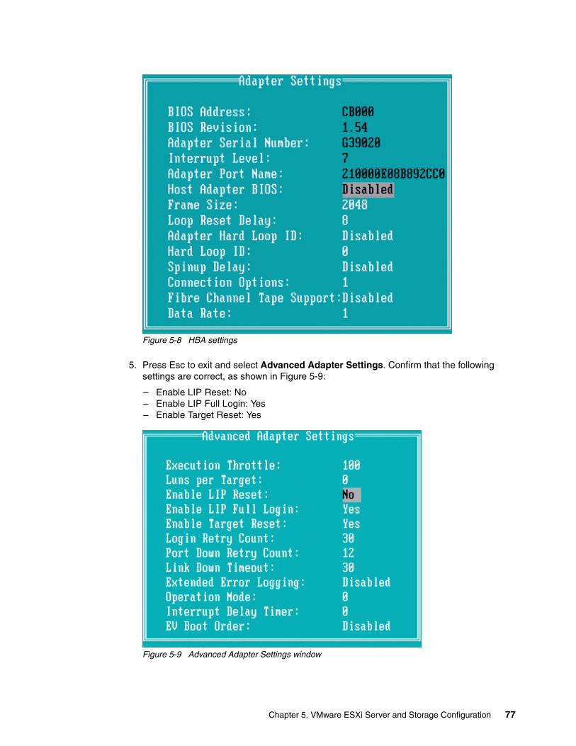
Figure 5-8 HBA settings
5. Press Esc to exit and select Advanced Adapter Settings. Confirm that the following settings are correct, as shown in Figure 5-9:
– Enable LIP Reset: No– Enable LIP Full Login: Yes– Enable Target Reset: Yes
Figure 5-9 Advanced Adapter Settings window
Chapter 5. VMware ESXi Server and Storage Configuration 77
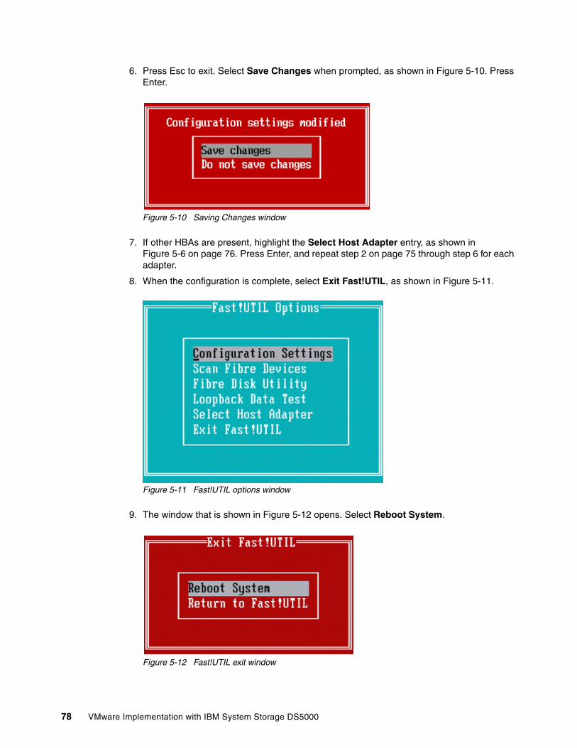
6. Press Esc to exit. Select Save Changes when prompted, as shown in Figure 5-10. Press Enter.
Figure 5-10 Saving Changes window
7. If other HBAs are present, highlight the Select Host Adapter entry, as shown in Figure 5-6 on page 76. Press Enter, and repeat step 2 on page 75 through step 6 for each adapter.
8. When the configuration is complete, select Exit Fast!UTIL, as shown in Figure 5-11.
Figure 5-11 Fast!UTIL options window
9. The window that is shown in Figure 5-12 opens. Select Reboot System.
Figure 5-12 Fast!UTIL exit window
78 VMware Implementation with IBM System Storage DS5000
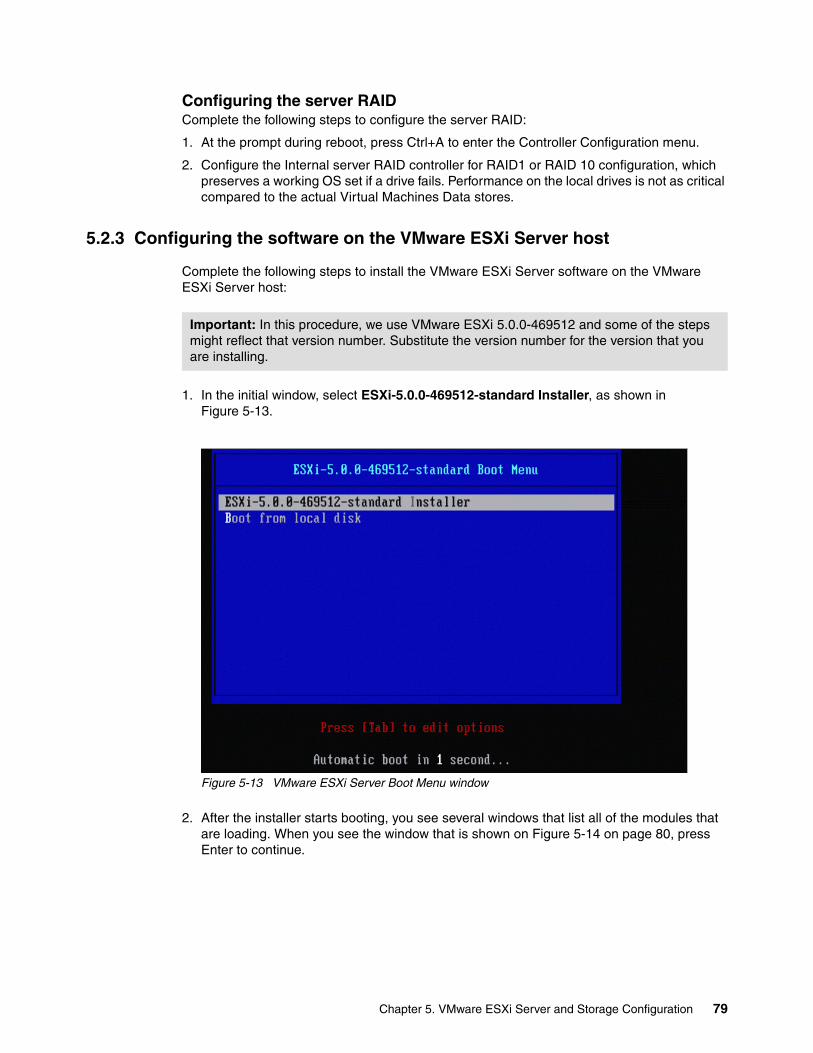
Configuring the server RAIDComplete the following steps to configure the server RAID:
1. At the prompt during reboot, press Ctrl+A to enter the Controller Configuration menu.
2. Configure the Internal server RAID controller for RAID1 or RAID 10 configuration, which preserves a working OS set if a drive fails. Performance on the local drives is not as critical compared to the actual Virtual Machines Data stores.
5.2.3 Configuring the software on the VMware ESXi Server host
Complete the following steps to install the VMware ESXi Server software on the VMware ESXi Server host:
1. In the initial window, select ESXi-5.0.0-469512-standard Installer, as shown in Figure 5-13.
Figure 5-13 VMware ESXi Server Boot Menu window
2. After the installer starts booting, you see several windows that list all of the modules that are loading. When you see the window that is shown on Figure 5-14 on page 80, press Enter to continue.
Important: In this procedure, we use VMware ESXi 5.0.0-469512 and some of the steps might reflect that version number. Substitute the version number for the version that you are installing.
Chapter 5. VMware ESXi Server and Storage Configuration 79
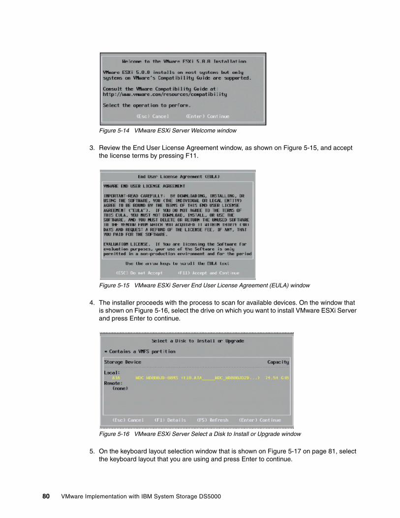
Figure 5-14 VMware ESXi Server Welcome window
3. Review the End User License Agreement window, as shown on Figure 5-15, and accept the license terms by pressing F11.
Figure 5-15 VMware ESXi Server End User License Agreement (EULA) window
4. The installer proceeds with the process to scan for available devices. On the window that is shown on Figure 5-16, select the drive on which you want to install VMware ESXi Server and press Enter to continue.
Figure 5-16 VMware ESXi Server Select a Disk to Install or Upgrade window
5. On the keyboard layout selection window that is shown on Figure 5-17 on page 81, select the keyboard layout that you are using and press Enter to continue.
80 VMware Implementation with IBM System Storage DS5000
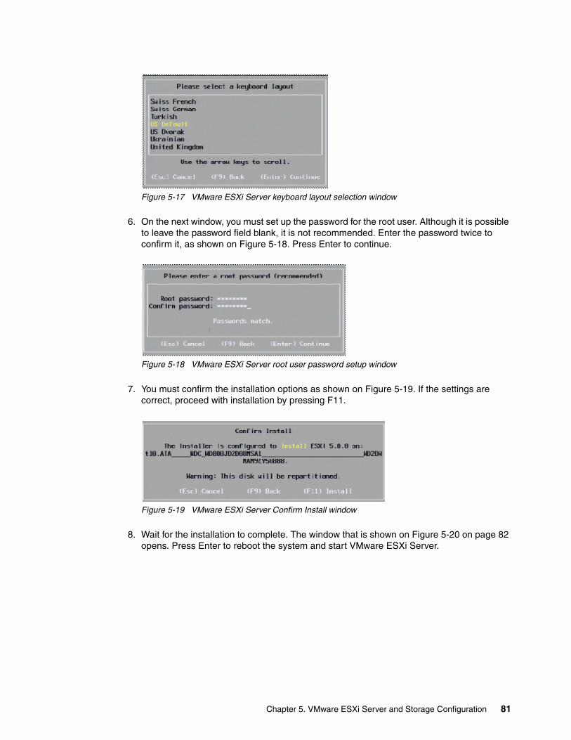
Figure 5-17 VMware ESXi Server keyboard layout selection window
6. On the next window, you must set up the password for the root user. Although it is possible to leave the password field blank, it is not recommended. Enter the password twice to confirm it, as shown on Figure 5-18. Press Enter to continue.
Figure 5-18 VMware ESXi Server root user password setup window
7. You must confirm the installation options as shown on Figure 5-19. If the settings are correct, proceed with installation by pressing F11.
Figure 5-19 VMware ESXi Server Confirm Install window
8. Wait for the installation to complete. The window that is shown on Figure 5-20 on page 82 opens. Press Enter to reboot the system and start VMware ESXi Server.
Chapter 5. VMware ESXi Server and Storage Configuration 81
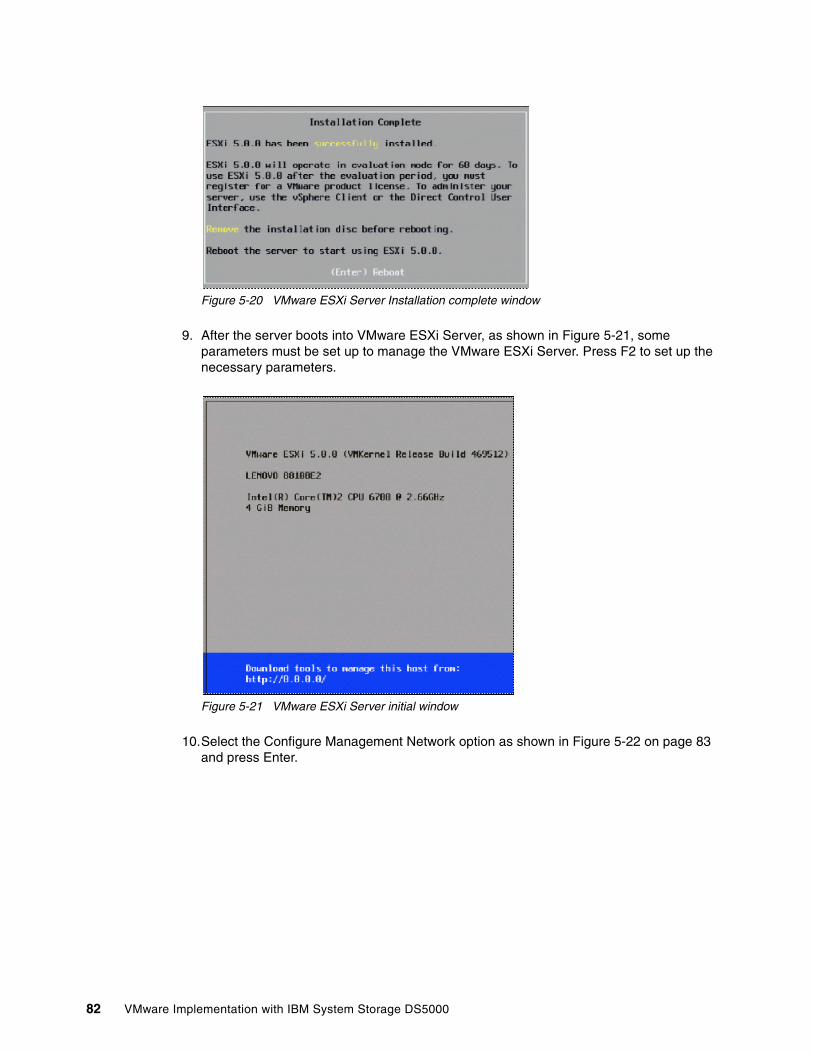
Figure 5-20 VMware ESXi Server Installation complete window
9. After the server boots into VMware ESXi Server, as shown in Figure 5-21, some parameters must be set up to manage the VMware ESXi Server. Press F2 to set up the necessary parameters.
Figure 5-21 VMware ESXi Server initial window
10.Select the Configure Management Network option as shown in Figure 5-22 on page 83 and press Enter.
82 VMware Implementation with IBM System Storage DS5000
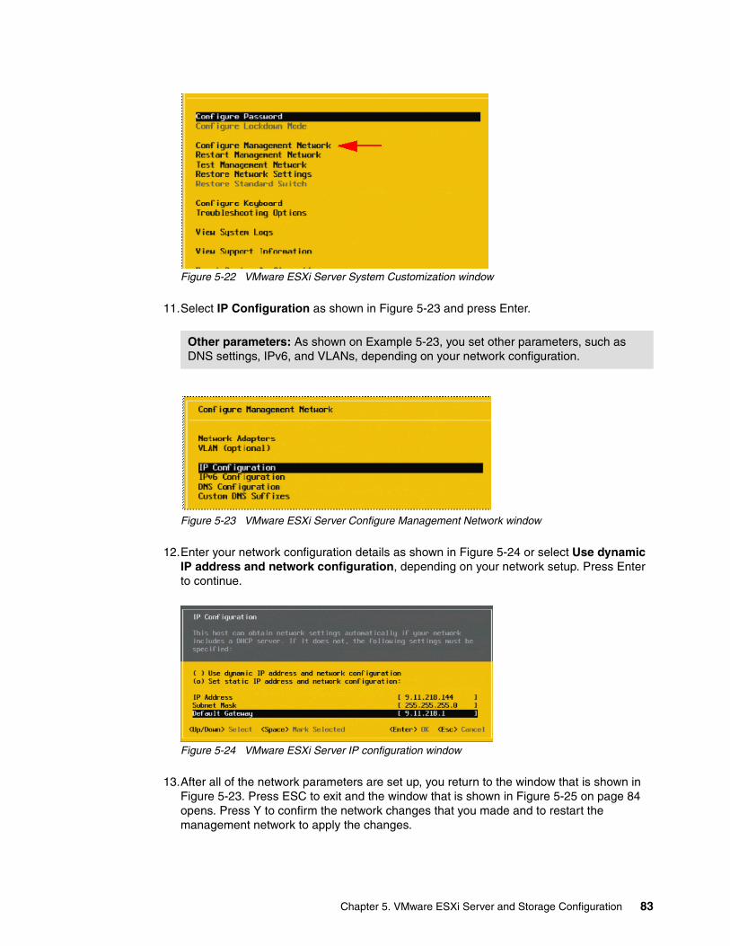
Figure 5-22 VMware ESXi Server System Customization window
11.Select IP Configuration as shown in Figure 5-23 and press Enter.
Figure 5-23 VMware ESXi Server Configure Management Network window
12.Enter your network configuration details as shown in Figure 5-24 or select Use dynamic IP address and network configuration, depending on your network setup. Press Enter to continue.
Figure 5-24 VMware ESXi Server IP configuration window
13.After all of the network parameters are set up, you return to the window that is shown in Figure 5-23. Press ESC to exit and the window that is shown in Figure 5-25 on page 84 opens. Press Y to confirm the network changes that you made and to restart the management network to apply the changes.
Other parameters: As shown on Example 5-23, you set other parameters, such as DNS settings, IPv6, and VLANs, depending on your network configuration.
Chapter 5. VMware ESXi Server and Storage Configuration 83
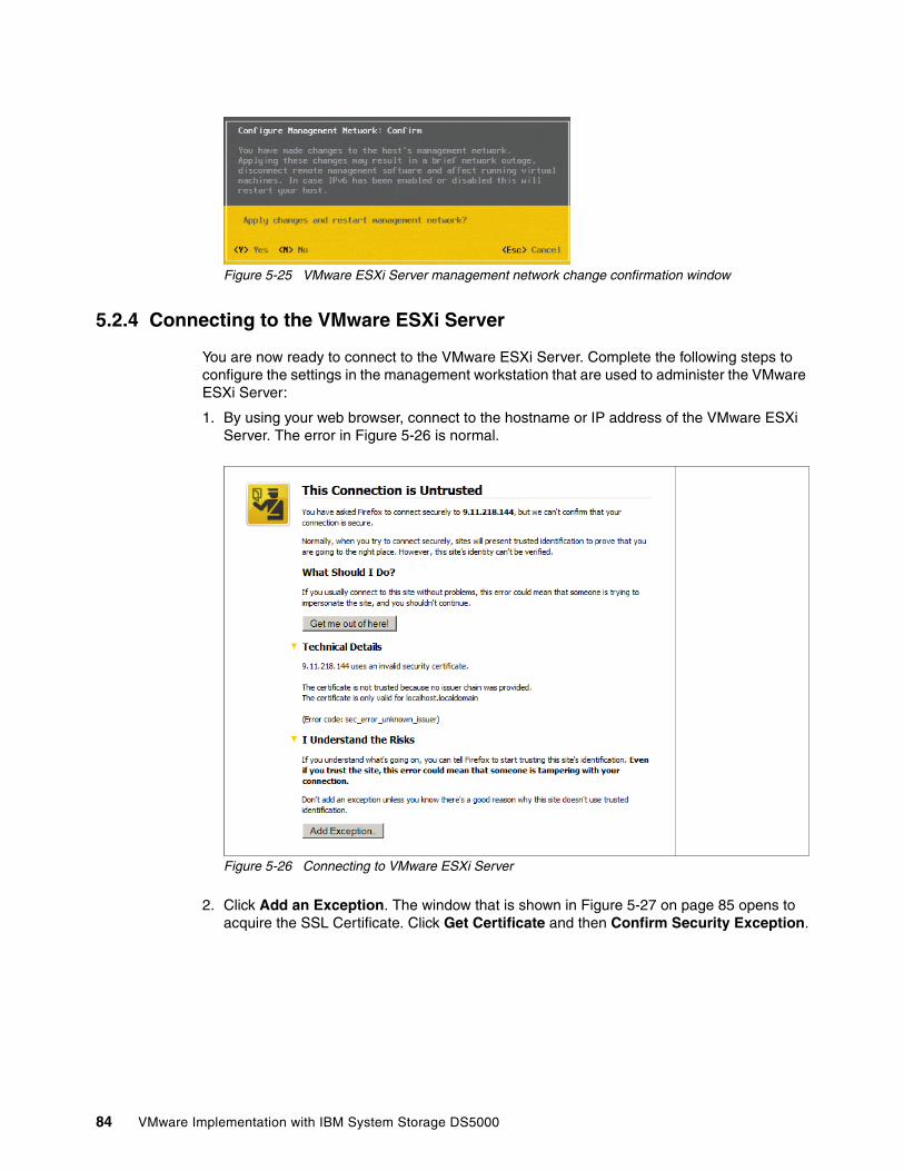
Figure 5-25 VMware ESXi Server management network change confirmation window
5.2.4 Connecting to the VMware ESXi Server
You are now ready to connect to the VMware ESXi Server. Complete the following steps to configure the settings in the management workstation that are used to administer the VMware ESXi Server:
1. By using your web browser, connect to the hostname or IP address of the VMware ESXi Server. The error in Figure 5-26 is normal.
Figure 5-26 Connecting to VMware ESXi Server
2. Click Add an Exception. The window that is shown in Figure 5-27 on page 85 opens to acquire the SSL Certificate. Click Get Certificate and then Confirm Security Exception.
84 VMware Implementation with IBM System Storage DS5000
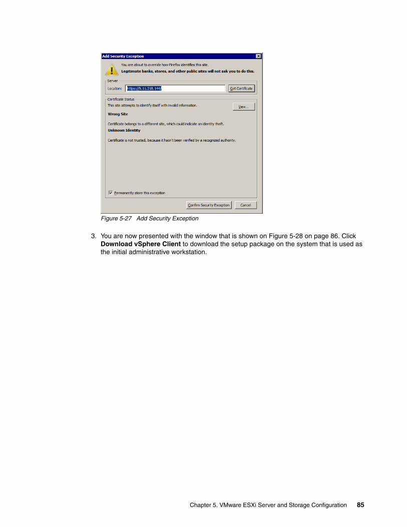
Figure 5-27 Add Security Exception
3. You are now presented with the window that is shown on Figure 5-28 on page 86. Click Download vSphere Client to download the setup package on the system that is used as the initial administrative workstation.
Chapter 5. VMware ESXi Server and Storage Configuration 85
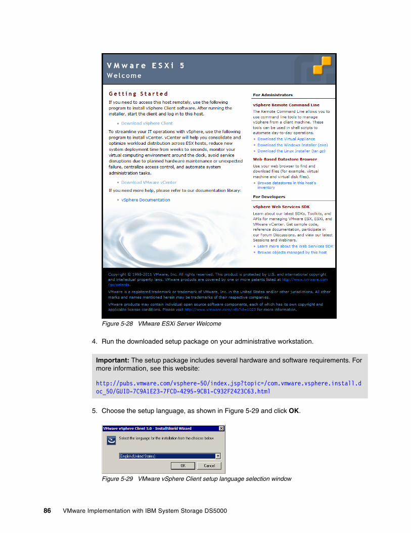
Figure 5-28 VMware ESXi Server Welcome
4. Run the downloaded setup package on your administrative workstation.
5. Choose the setup language, as shown in Figure 5-29 and click OK.
Figure 5-29 VMware vSphere Client setup language selection window
Important: The setup package includes several hardware and software requirements. For more information, see this website:
http://pubs.vmware.com/vsphere-50/index.jsp?topic=/com.vmware.vsphere.install.doc_50/GUID-7C9A1E23-7FCD-4295-9CB1-C932F2423C63.html
86 VMware Implementation with IBM System Storage DS5000
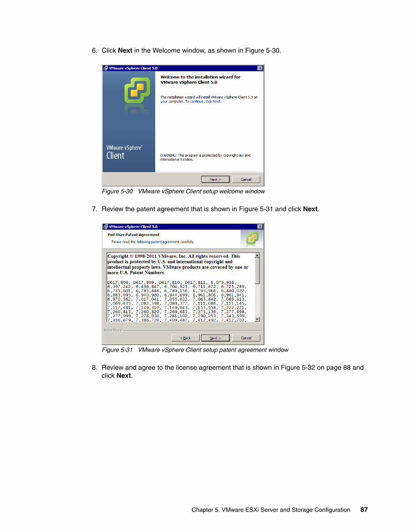
6. Click Next in the Welcome window, as shown in Figure 5-30.
Figure 5-30 VMware vSphere Client setup welcome window
7. Review the patent agreement that is shown in Figure 5-31 and click Next.
Figure 5-31 VMware vSphere Client setup patent agreement window
8. Review and agree to the license agreement that is shown in Figure 5-32 on page 88 and click Next.
Chapter 5. VMware ESXi Server and Storage Configuration 87
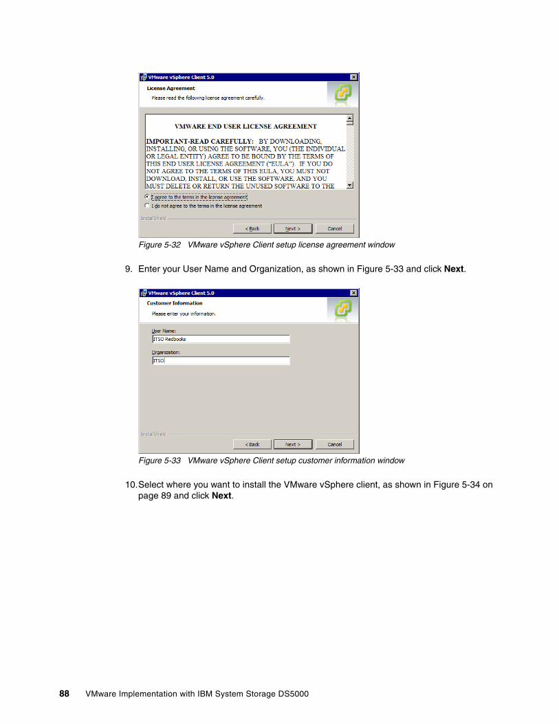
Figure 5-32 VMware vSphere Client setup license agreement window
9. Enter your User Name and Organization, as shown in Figure 5-33 and click Next.
Figure 5-33 VMware vSphere Client setup customer information window
10.Select where you want to install the VMware vSphere client, as shown in Figure 5-34 on page 89 and click Next.
88 VMware Implementation with IBM System Storage DS5000
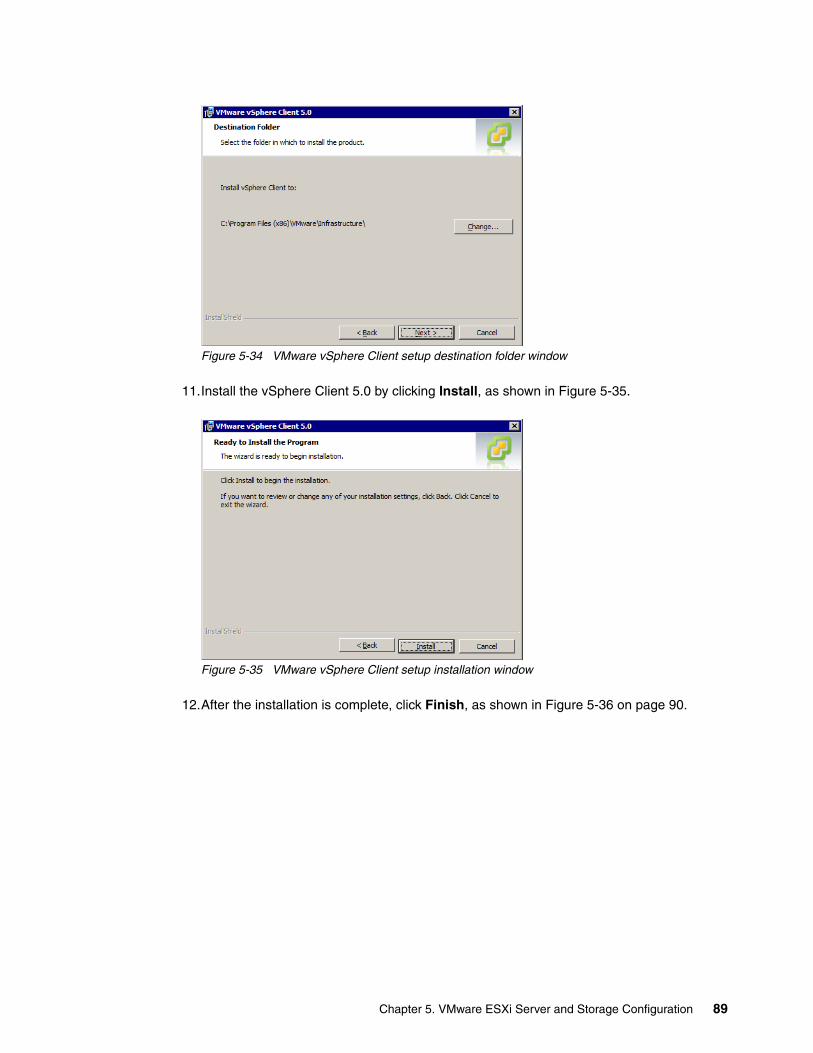
Figure 5-34 VMware vSphere Client setup destination folder window
11.Install the vSphere Client 5.0 by clicking Install, as shown in Figure 5-35.
Figure 5-35 VMware vSphere Client setup installation window
12.After the installation is complete, click Finish, as shown in Figure 5-36 on page 90.
Chapter 5. VMware ESXi Server and Storage Configuration 89
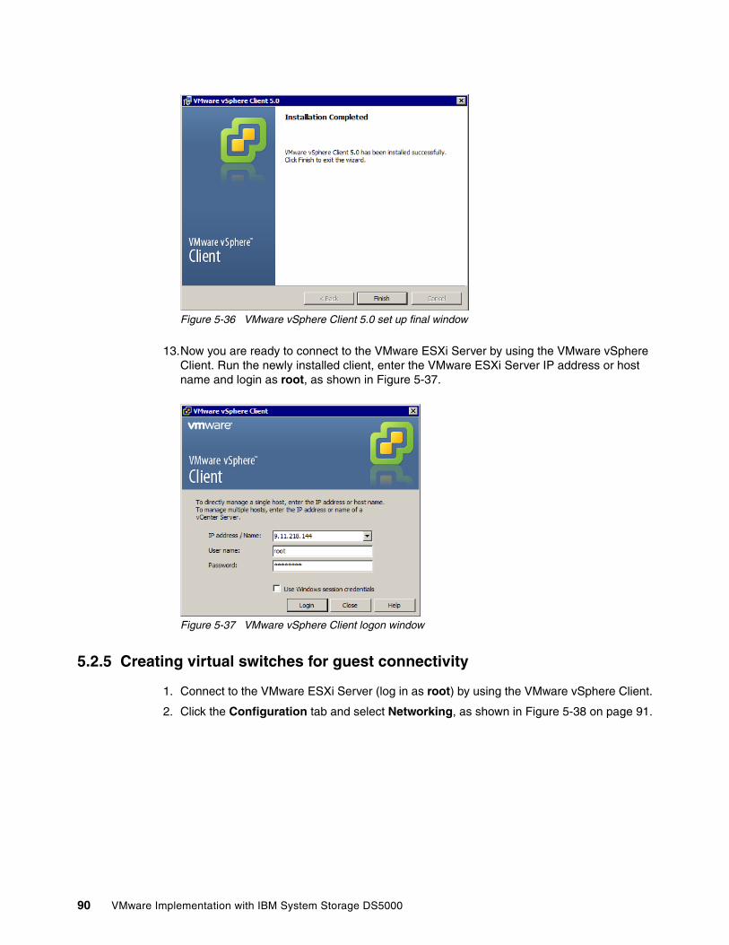
Figure 5-36 VMware vSphere Client 5.0 set up final window
13.Now you are ready to connect to the VMware ESXi Server by using the VMware vSphere Client. Run the newly installed client, enter the VMware ESXi Server IP address or host name and login as root, as shown in Figure 5-37.
Figure 5-37 VMware vSphere Client logon window
5.2.5 Creating virtual switches for guest connectivity
1. Connect to the VMware ESXi Server (log in as root) by using the VMware vSphere Client.
2. Click the Configuration tab and select Networking, as shown in Figure 5-38 on page 91.
90 VMware Implementation with IBM System Storage DS5000
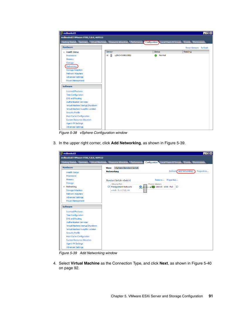
Figure 5-38 vSphere Configuration window
3. In the upper right corner, click Add Networking, as shown in Figure 5-39.
Figure 5-39 Add Networking window
4. Select Virtual Machine as the Connection Type, and click Next, as shown in Figure 5-40 on page 92.
Chapter 5. VMware ESXi Server and Storage Configuration 91
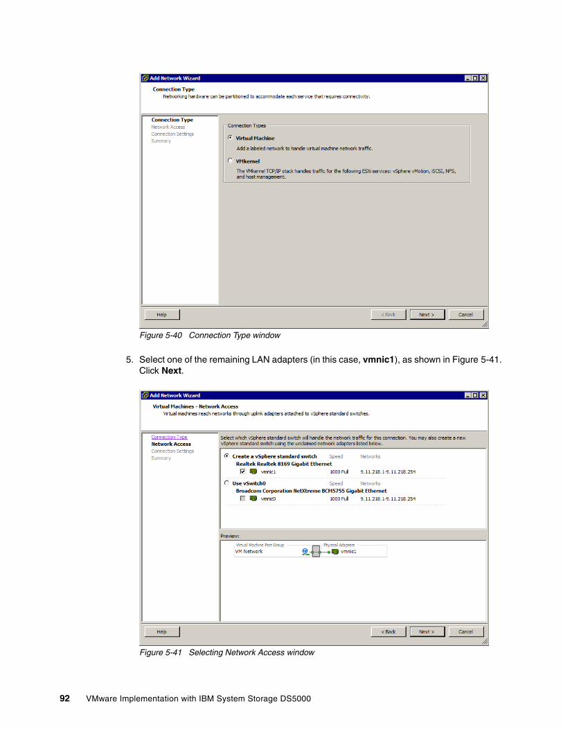
Figure 5-40 Connection Type window
5. Select one of the remaining LAN adapters (in this case, vmnic1), as shown in Figure 5-41. Click Next.
Figure 5-41 Selecting Network Access window
92 VMware Implementation with IBM System Storage DS5000
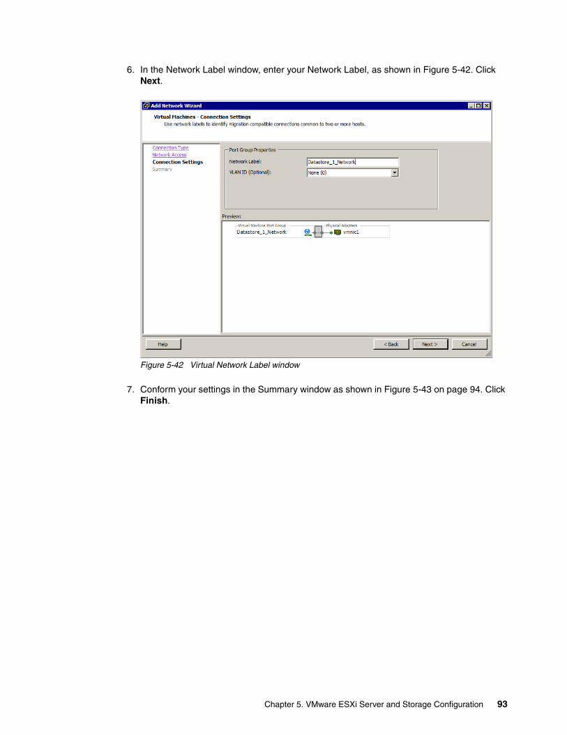
6. In the Network Label window, enter your Network Label, as shown in Figure 5-42. Click Next.
Figure 5-42 Virtual Network Label window
7. Conform your settings in the Summary window as shown in Figure 5-43 on page 94. Click Finish.
Chapter 5. VMware ESXi Server and Storage Configuration 93
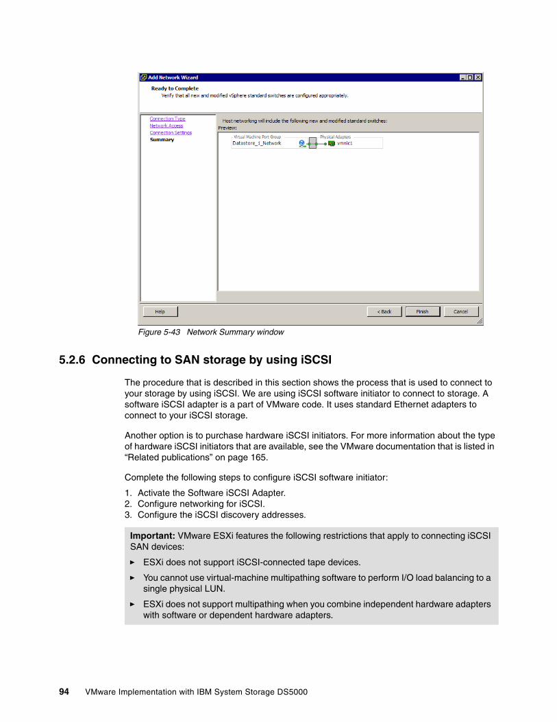
Figure 5-43 Network Summary window
5.2.6 Connecting to SAN storage by using iSCSI
The procedure that is described in this section shows the process that is used to connect to your storage by using iSCSI. We are using iSCSI software initiator to connect to storage. A software iSCSI adapter is a part of VMware code. It uses standard Ethernet adapters to connect to your iSCSI storage.
Another option is to purchase hardware iSCSI initiators. For more information about the type of hardware iSCSI initiators that are available, see the VMware documentation that is listed in “Related publications” on page 165.
Complete the following steps to configure iSCSI software initiator:
1. Activate the Software iSCSI Adapter.2. Configure networking for iSCSI.3. Configure the iSCSI discovery addresses.
Important: VMware ESXi features the following restrictions that apply to connecting iSCSI SAN devices:
� ESXi does not support iSCSI-connected tape devices.
� You cannot use virtual-machine multipathing software to perform I/O load balancing to a single physical LUN.
� ESXi does not support multipathing when you combine independent hardware adapters with software or dependent hardware adapters.
94 VMware Implementation with IBM System Storage DS5000
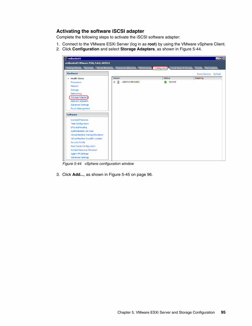
Activating the software iSCSI adapterComplete the following steps to activate the iSCSI software adapter:
1. Connect to the VMware ESXi Server (log in as root) by using the VMware vSphere Client.2. Click Configuration and select Storage Adapters, as shown in Figure 5-44.
Figure 5-44 vSphere configuration window
3. Click Add..., as shown in Figure 5-45 on page 96.
Chapter 5. VMware ESXi Server and Storage Configuration 95
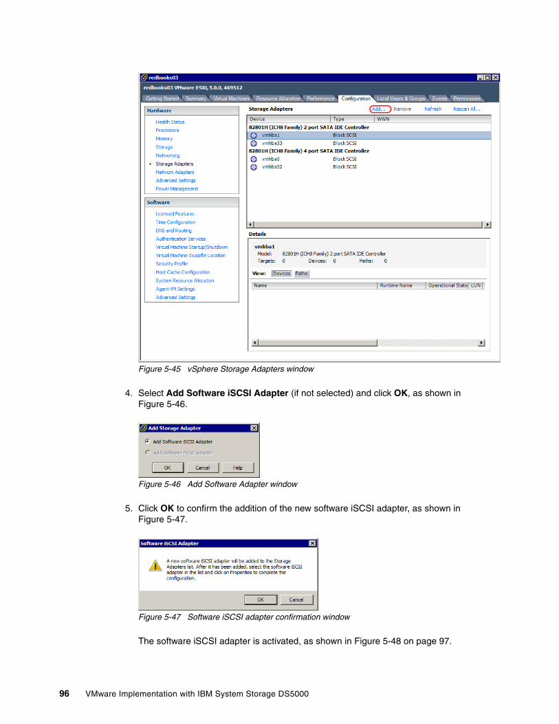
Figure 5-45 vSphere Storage Adapters window
4. Select Add Software iSCSI Adapter (if not selected) and click OK, as shown in Figure 5-46.
Figure 5-46 Add Software Adapter window
5. Click OK to confirm the addition of the new software iSCSI adapter, as shown in Figure 5-47.
Figure 5-47 Software iSCSI adapter confirmation window
The software iSCSI adapter is activated, as shown in Figure 5-48 on page 97.
96 VMware Implementation with IBM System Storage DS5000
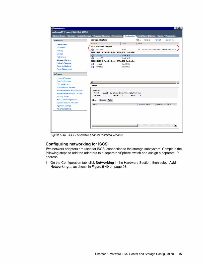
Figure 5-48 iSCSI Software Adapter installed window
Configuring networking for iSCSITwo network adapters are used for iSCSI connection to the storage subsystem. Complete the following steps to add the adapters to a separate vSphere switch and assign a separate IP address:
1. On the Configuration tab, click Networking in the Hardware Section, then select Add Networking..., as shown in Figure 5-49 on page 98.
Chapter 5. VMware ESXi Server and Storage Configuration 97
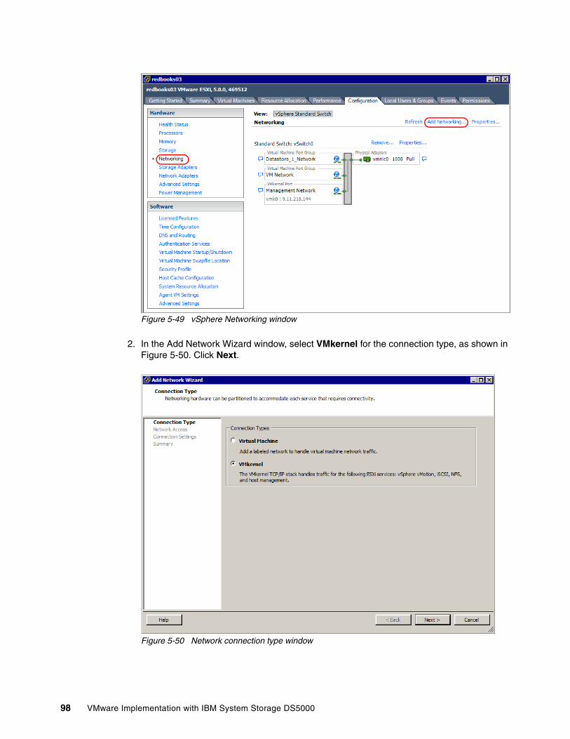
Figure 5-49 vSphere Networking window
2. In the Add Network Wizard window, select VMkernel for the connection type, as shown in Figure 5-50. Click Next.
Figure 5-50 Network connection type window
98 VMware Implementation with IBM System Storage DS5000
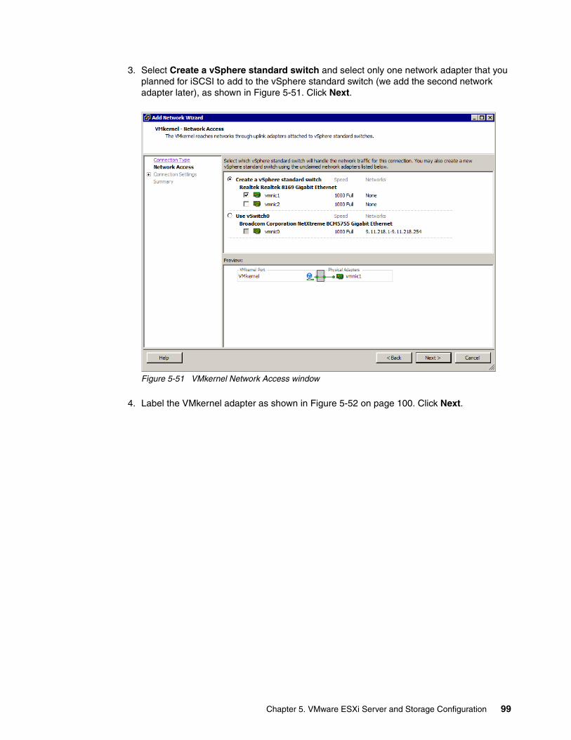
3. Select Create a vSphere standard switch and select only one network adapter that you planned for iSCSI to add to the vSphere standard switch (we add the second network adapter later), as shown in Figure 5-51. Click Next.
Figure 5-51 VMkernel Network Access window
4. Label the VMkernel adapter as shown in Figure 5-52 on page 100. Click Next.
Chapter 5. VMware ESXi Server and Storage Configuration 99
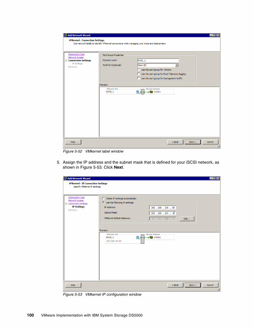
Figure 5-52 VMkernel label window
5. Assign the IP address and the subnet mask that is defined for your iSCSI network, as shown in Figure 5-53. Click Next.
Figure 5-53 VMkernel IP configuration window
100 VMware Implementation with IBM System Storage DS5000
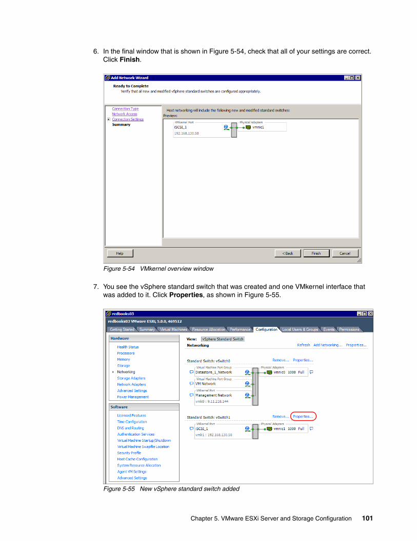
6. In the final window that is shown in Figure 5-54, check that all of your settings are correct. Click Finish.
Figure 5-54 VMkernel overview window
7. You see the vSphere standard switch that was created and one VMkernel interface that was added to it. Click Properties, as shown in Figure 5-55.
Figure 5-55 New vSphere standard switch added
Chapter 5. VMware ESXi Server and Storage Configuration 101
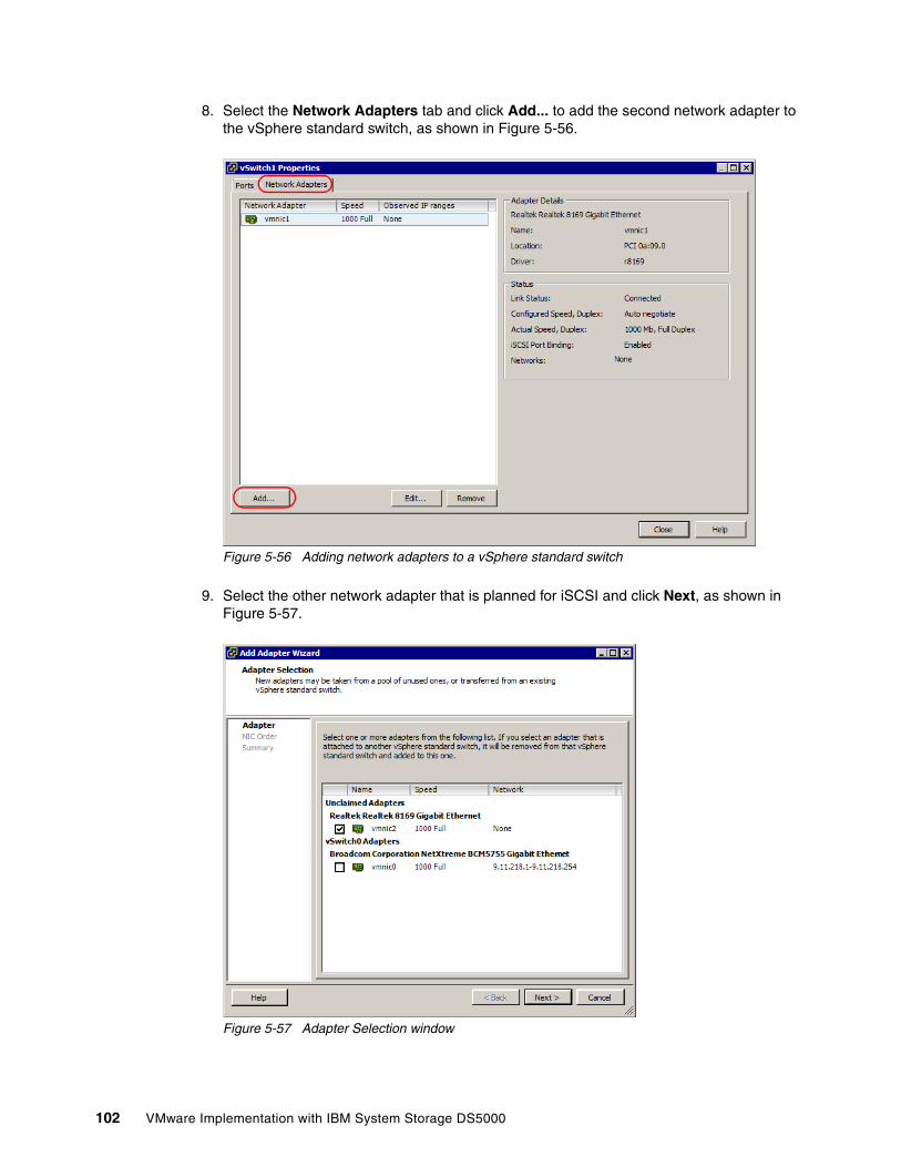
8. Select the Network Adapters tab and click Add... to add the second network adapter to the vSphere standard switch, as shown in Figure 5-56.
Figure 5-56 Adding network adapters to a vSphere standard switch
9. Select the other network adapter that is planned for iSCSI and click Next, as shown in Figure 5-57.
Figure 5-57 Adapter Selection window
102 VMware Implementation with IBM System Storage DS5000
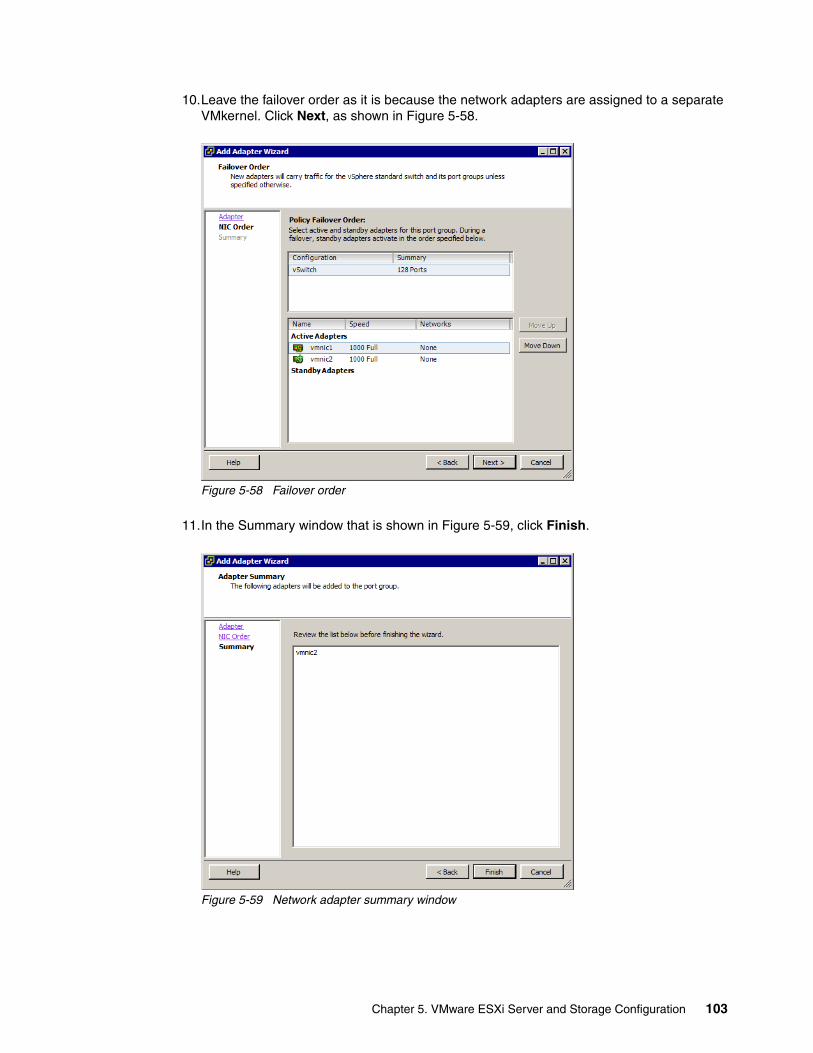
10.Leave the failover order as it is because the network adapters are assigned to a separate VMkernel. Click Next, as shown in Figure 5-58.
Figure 5-58 Failover order
11.In the Summary window that is shown in Figure 5-59, click Finish.
Figure 5-59 Network adapter summary window
Chapter 5. VMware ESXi Server and Storage Configuration 103
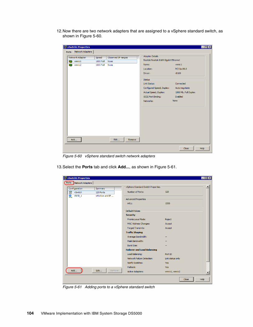
12.Now there are two network adapters that are assigned to a vSphere standard switch, as shown in Figure 5-60.
Figure 5-60 vSphere standard switch network adapters
13.Select the Ports tab and click Add..., as shown in Figure 5-61.
Figure 5-61 Adding ports to a vSphere standard switch
104 VMware Implementation with IBM System Storage DS5000
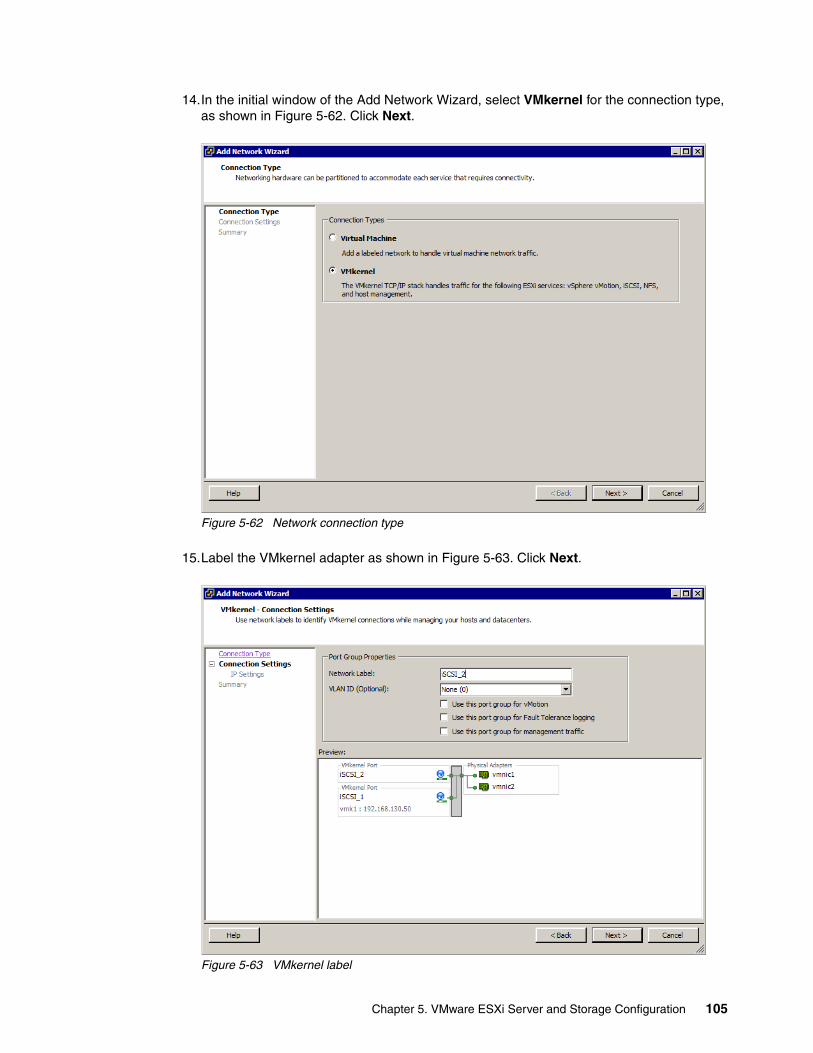
14.In the initial window of the Add Network Wizard, select VMkernel for the connection type, as shown in Figure 5-62. Click Next.
Figure 5-62 Network connection type
15.Label the VMkernel adapter as shown in Figure 5-63. Click Next.
Figure 5-63 VMkernel label
Chapter 5. VMware ESXi Server and Storage Configuration 105
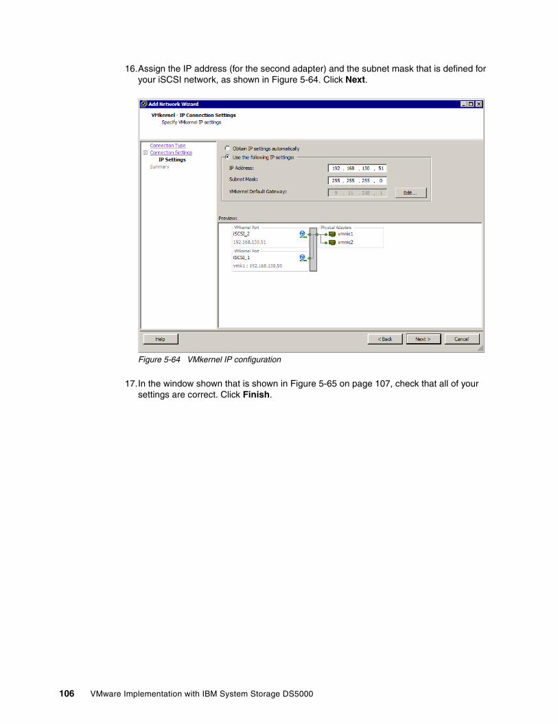
16.Assign the IP address (for the second adapter) and the subnet mask that is defined for your iSCSI network, as shown in Figure 5-64. Click Next.
Figure 5-64 VMkernel IP configuration
17.In the window shown that is shown in Figure 5-65 on page 107, check that all of your settings are correct. Click Finish.
106 VMware Implementation with IBM System Storage DS5000
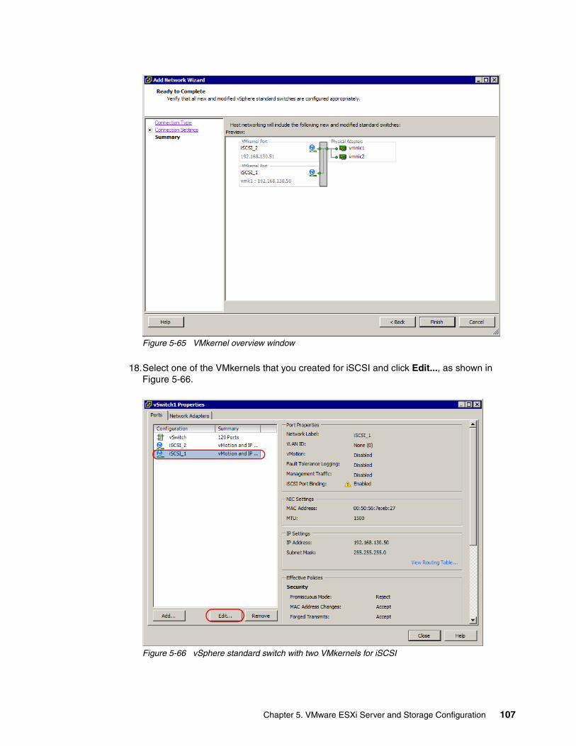
Figure 5-65 VMkernel overview window
18.Select one of the VMkernels that you created for iSCSI and click Edit..., as shown in Figure 5-66.
Figure 5-66 vSphere standard switch with two VMkernels for iSCSI
Chapter 5. VMware ESXi Server and Storage Configuration 107
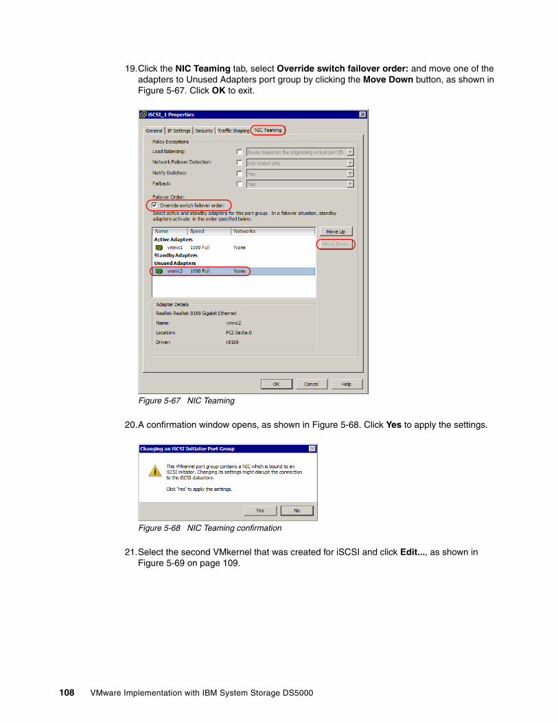
19.Click the NIC Teaming tab, select Override switch failover order: and move one of the adapters to Unused Adapters port group by clicking the Move Down button, as shown in Figure 5-67. Click OK to exit.
Figure 5-67 NIC Teaming
20.A confirmation window opens, as shown in Figure 5-68. Click Yes to apply the settings.
Figure 5-68 NIC Teaming confirmation
21.Select the second VMkernel that was created for iSCSI and click Edit..., as shown in Figure 5-69 on page 109.
108 VMware Implementation with IBM System Storage DS5000
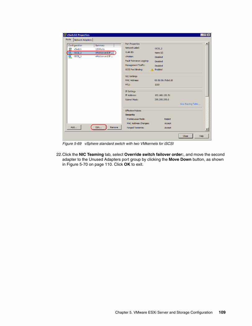
Figure 5-69 vSphere standard switch with two VMkernels for iSCSI
22.Click the NIC Teaming tab, select Override switch failover order:, and move the second adapter to the Unused Adapters port group by clicking the Move Down button, as shown in Figure 5-70 on page 110. Click OK to exit.
Chapter 5. VMware ESXi Server and Storage Configuration 109
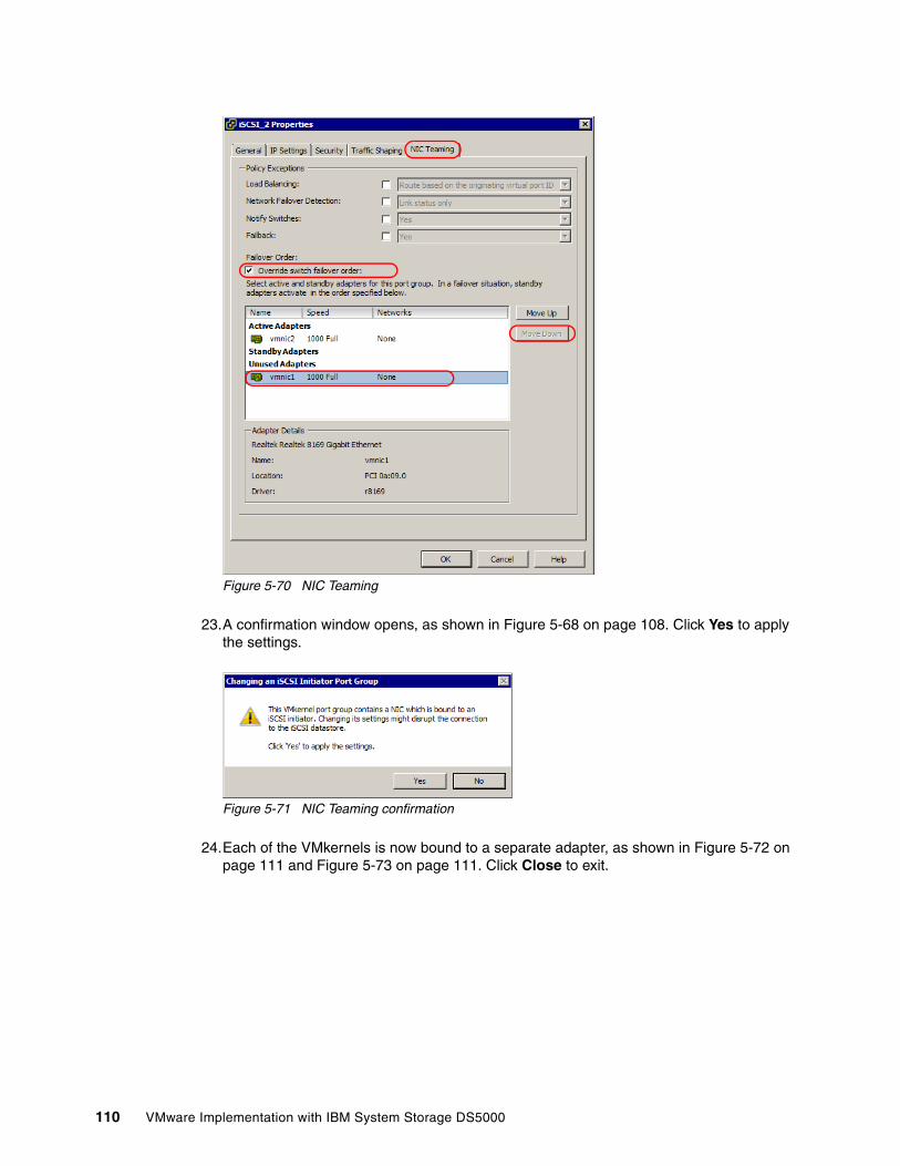
Figure 5-70 NIC Teaming
23.A confirmation window opens, as shown in Figure 5-68 on page 108. Click Yes to apply the settings.
Figure 5-71 NIC Teaming confirmation
24.Each of the VMkernels is now bound to a separate adapter, as shown in Figure 5-72 on page 111 and Figure 5-73 on page 111. Click Close to exit.
110 VMware Implementation with IBM System Storage DS5000
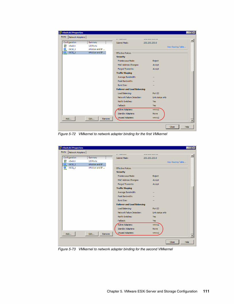
Figure 5-72 VMkernel to network adapter binding for the first VMkernel
Figure 5-73 VMkernel to network adapter binding for the second VMkernel
Chapter 5. VMware ESXi Server and Storage Configuration 111
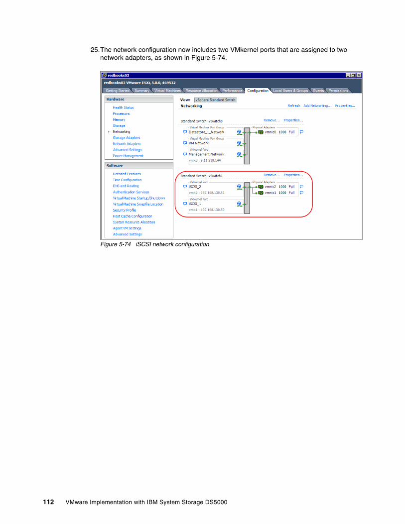
25.The network configuration now includes two VMkernel ports that are assigned to two network adapters, as shown in Figure 5-74.
Figure 5-74 iSCSI network configuration
112 VMware Implementation with IBM System Storage DS5000
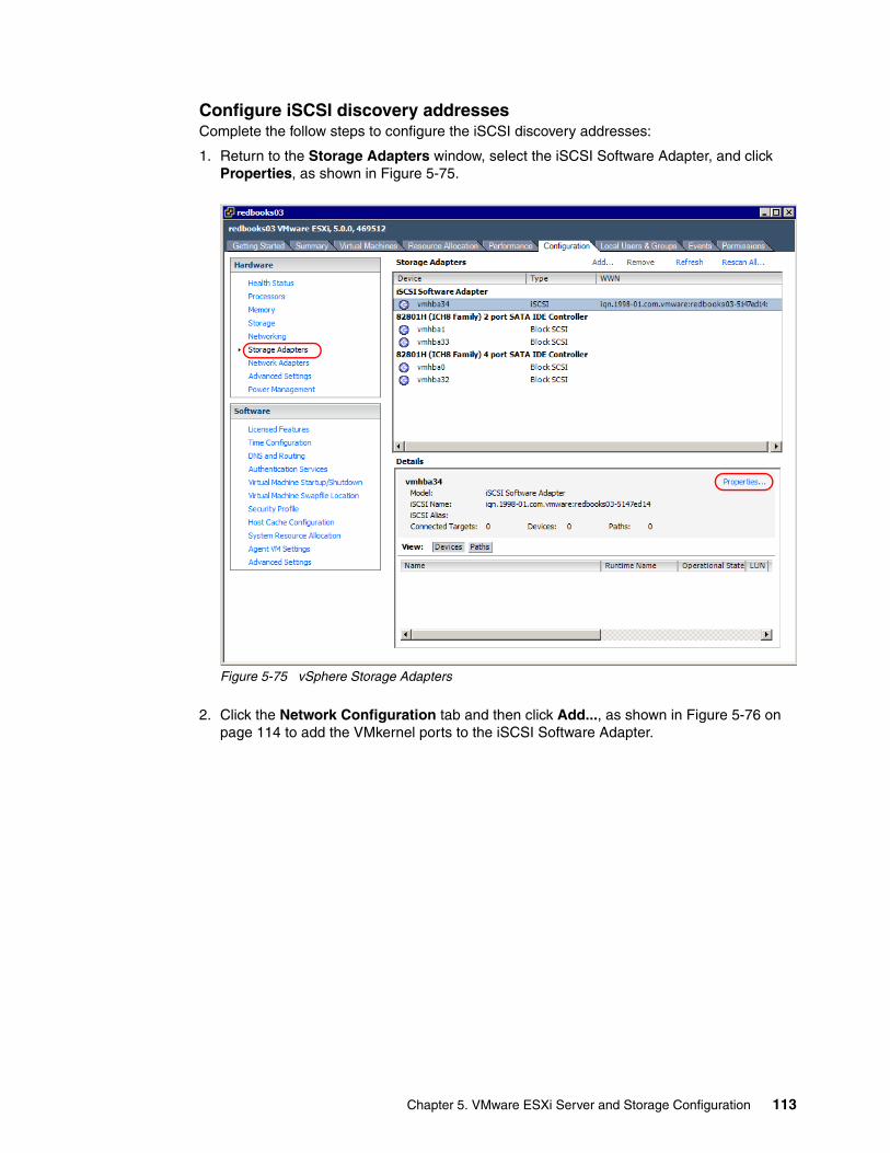
Configure iSCSI discovery addressesComplete the follow steps to configure the iSCSI discovery addresses:
1. Return to the Storage Adapters window, select the iSCSI Software Adapter, and click Properties, as shown in Figure 5-75.
Figure 5-75 vSphere Storage Adapters
2. Click the Network Configuration tab and then click Add..., as shown in Figure 5-76 on page 114 to add the VMkernel ports to the iSCSI Software Adapter.
Chapter 5. VMware ESXi Server and Storage Configuration 113
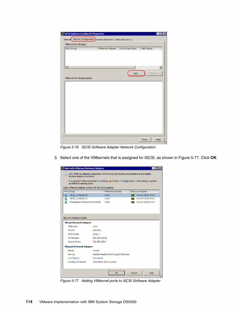
Figure 5-76 iSCSI Software Adapter Network Configuration
3. Select one of the VMkernels that is assigned for iSCSI, as shown in Figure 5-77. Click OK.
Figure 5-77 Adding VMkernel ports to iSCSI Software Adapter
114 VMware Implementation with IBM System Storage DS5000
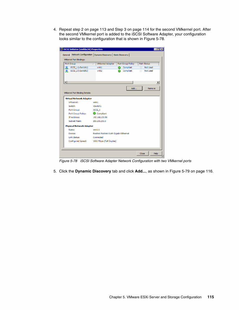
4. Repeat step 2 on page 113 and Step 3 on page 114 for the second VMkernel port. After the second VMkernel port is added to the iSCSI Software Adapter, your configuration looks similar to the configuration that is shown in Figure 5-78.
Figure 5-78 iSCSI Software Adapter Network Configuration with two VMkernel ports
5. Click the Dynamic Discovery tab and click Add..., as shown in Figure 5-79 on page 116.
Chapter 5. VMware ESXi Server and Storage Configuration 115
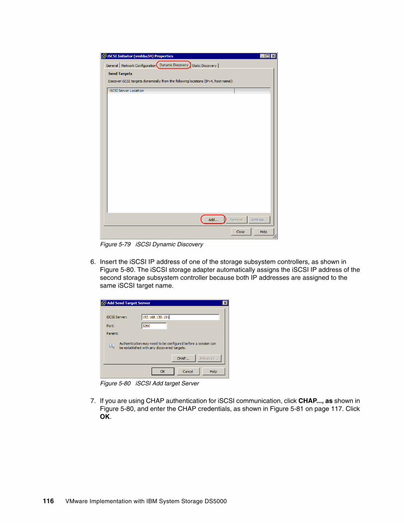
Figure 5-79 iSCSI Dynamic Discovery
6. Insert the iSCSI IP address of one of the storage subsystem controllers, as shown in Figure 5-80. The iSCSI storage adapter automatically assigns the iSCSI IP address of the second storage subsystem controller because both IP addresses are assigned to the same iSCSI target name.
Figure 5-80 iSCSI Add target Server
7. If you are using CHAP authentication for iSCSI communication, click CHAP..., as shown in Figure 5-80, and enter the CHAP credentials, as shown in Figure 5-81 on page 117. Click OK.
116 VMware Implementation with IBM System Storage DS5000
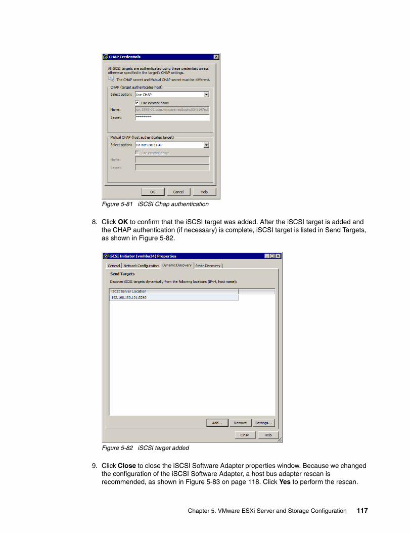
Figure 5-81 iSCSI Chap authentication
8. Click OK to confirm that the iSCSI target was added. After the iSCSI target is added and the CHAP authentication (if necessary) is complete, iSCSI target is listed in Send Targets, as shown in Figure 5-82.
Figure 5-82 iSCSI target added
9. Click Close to close the iSCSI Software Adapter properties window. Because we changed the configuration of the iSCSI Software Adapter, a host bus adapter rescan is recommended, as shown in Figure 5-83 on page 118. Click Yes to perform the rescan.
Chapter 5. VMware ESXi Server and Storage Configuration 117
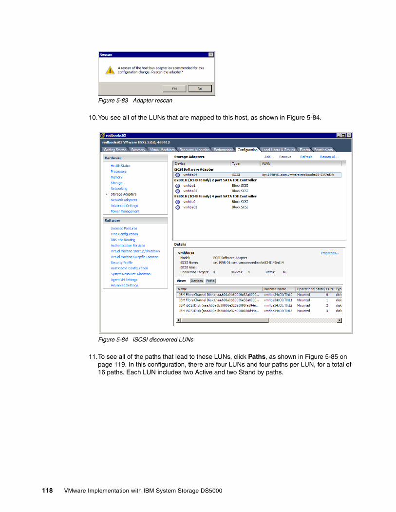
Figure 5-83 Adapter rescan
10.You see all of the LUNs that are mapped to this host, as shown in Figure 5-84.
Figure 5-84 iSCSI discovered LUNs
11.To see all of the paths that lead to these LUNs, click Paths, as shown in Figure 5-85 on page 119. In this configuration, there are four LUNs and four paths per LUN, for a total of 16 paths. Each LUN includes two Active and two Stand by paths.
118 VMware Implementation with IBM System Storage DS5000
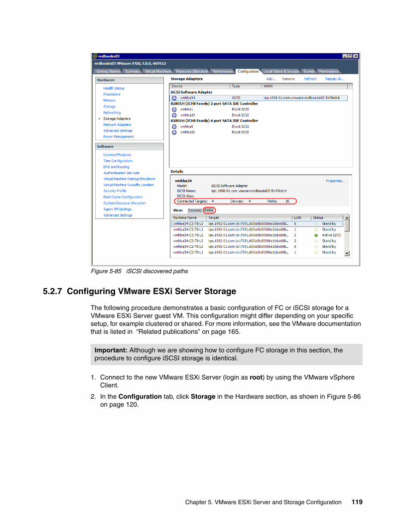
Figure 5-85 iSCSI discovered paths
5.2.7 Configuring VMware ESXi Server Storage
The following procedure demonstrates a basic configuration of FC or iSCSI storage for a VMware ESXi Server guest VM. This configuration might differ depending on your specific setup, for example clustered or shared. For more information, see the VMware documentation that is listed in “Related publications” on page 165.
1. Connect to the new VMware ESXi Server (login as root) by using the VMware vSphere Client.
2. In the Configuration tab, click Storage in the Hardware section, as shown in Figure 5-86 on page 120.
Important: Although we are showing how to configure FC storage in this section, the procedure to configure iSCSI storage is identical.
Chapter 5. VMware ESXi Server and Storage Configuration 119
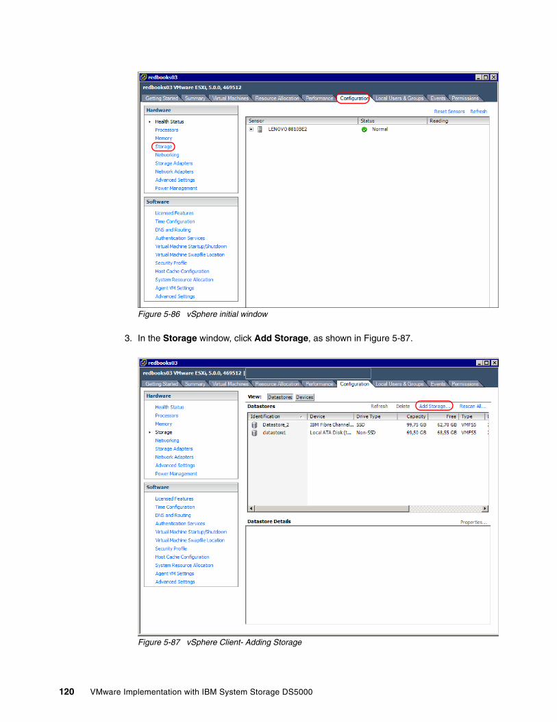
Figure 5-86 vSphere initial window
3. In the Storage window, click Add Storage, as shown in Figure 5-87.
Figure 5-87 vSphere Client- Adding Storage
120 VMware Implementation with IBM System Storage DS5000
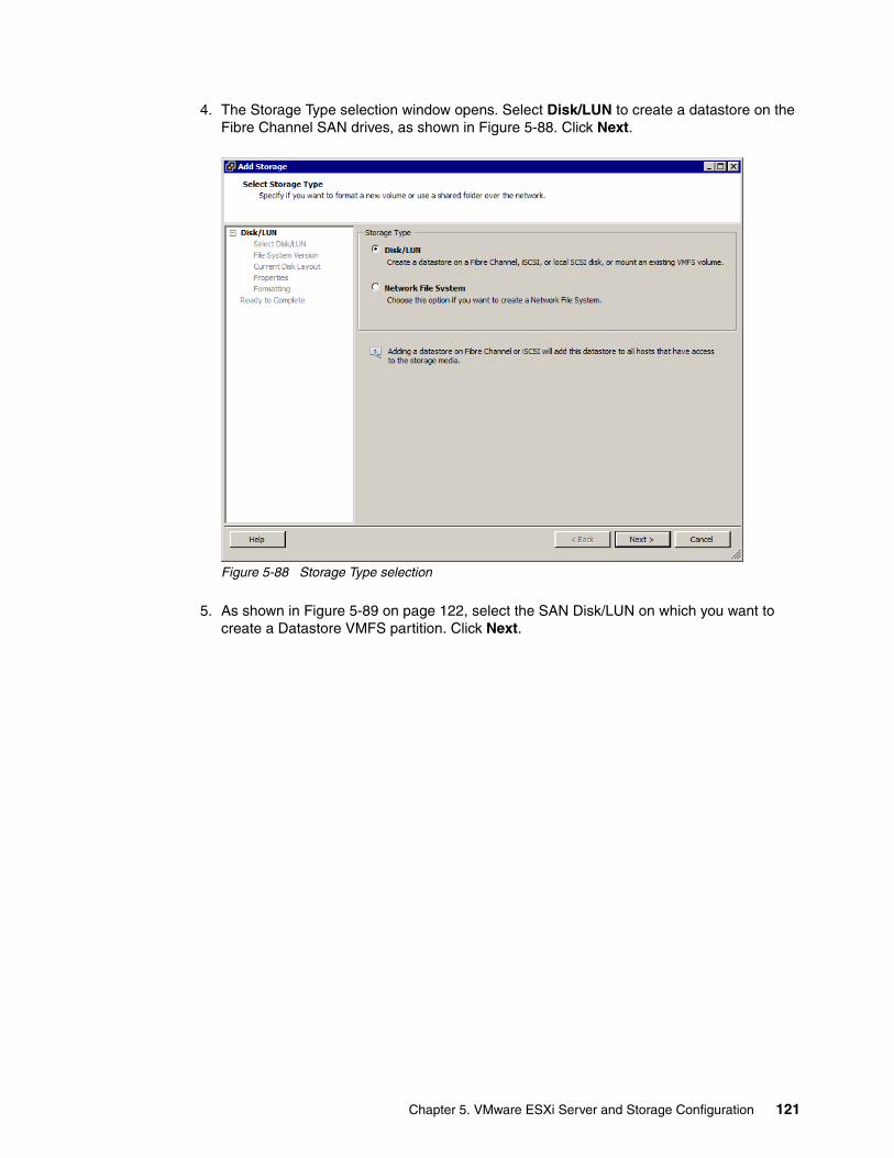
4. The Storage Type selection window opens. Select Disk/LUN to create a datastore on the Fibre Channel SAN drives, as shown in Figure 5-88. Click Next.
Figure 5-88 Storage Type selection
5. As shown in Figure 5-89 on page 122, select the SAN Disk/LUN on which you want to create a Datastore VMFS partition. Click Next.
Chapter 5. VMware ESXi Server and Storage Configuration 121
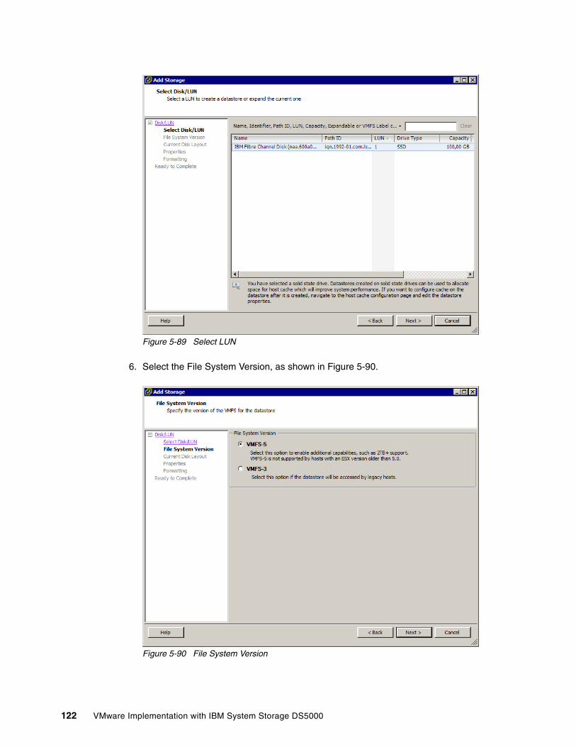
Figure 5-89 Select LUN
6. Select the File System Version, as shown in Figure 5-90.
Figure 5-90 File System Version
122 VMware Implementation with IBM System Storage DS5000
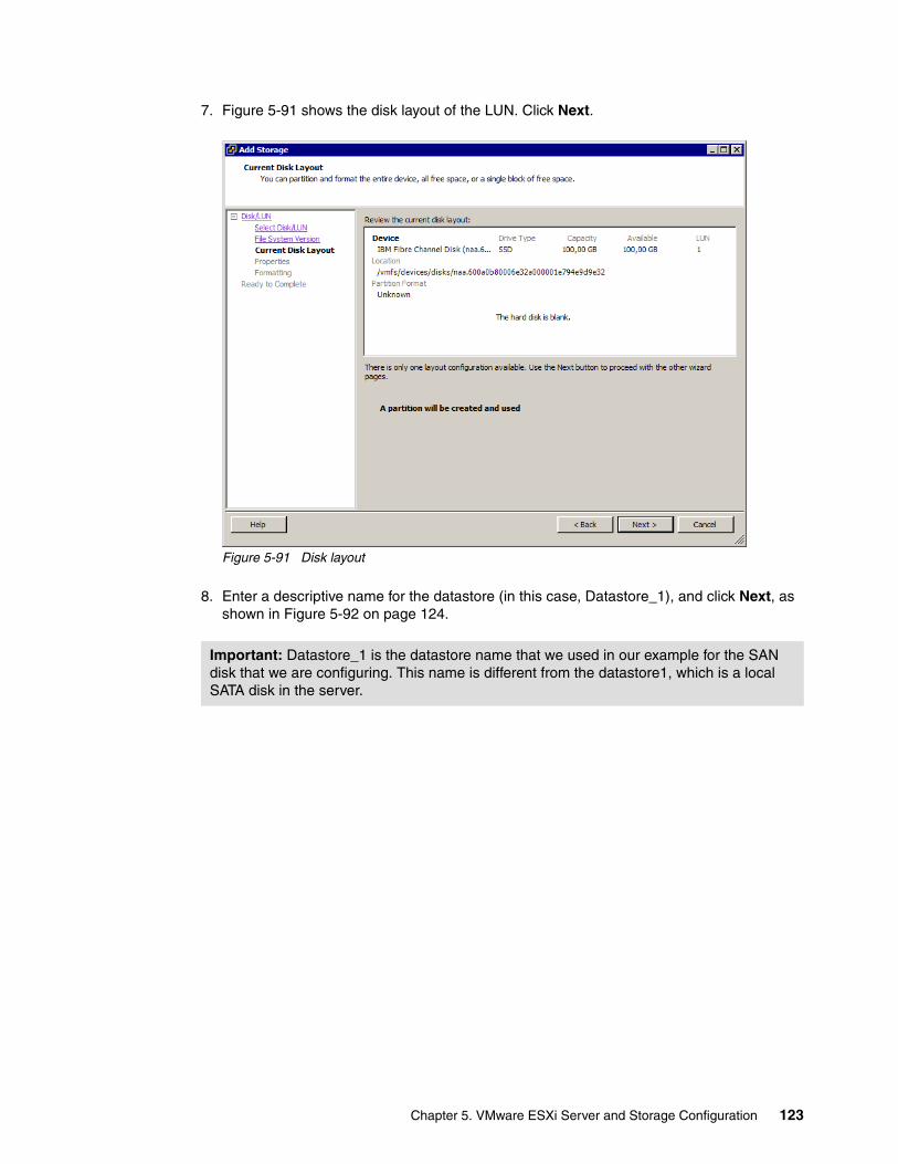
7. Figure 5-91 shows the disk layout of the LUN. Click Next.
Figure 5-91 Disk layout
8. Enter a descriptive name for the datastore (in this case, Datastore_1), and click Next, as shown in Figure 5-92 on page 124.
Important: Datastore_1 is the datastore name that we used in our example for the SAN disk that we are configuring. This name is different from the datastore1, which is a local SATA disk in the server.
Chapter 5. VMware ESXi Server and Storage Configuration 123
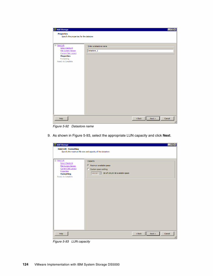
Figure 5-92 Datastore name
9. As shown in Figure 5-93, select the appropriate LUN capacity and click Next.
Figure 5-93 LUN capacity
124 VMware Implementation with IBM System Storage DS5000
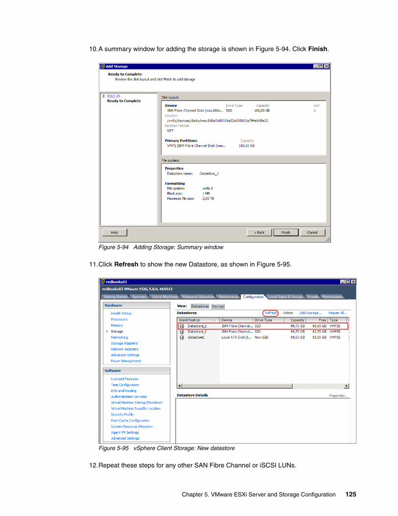
10.A summary window for adding the storage is shown in Figure 5-94. Click Finish.
Figure 5-94 Adding Storage: Summary window
11.Click Refresh to show the new Datastore, as shown in Figure 5-95.
Figure 5-95 vSphere Client Storage: New datastore
12.Repeat these steps for any other SAN Fibre Channel or iSCSI LUNs.
Chapter 5. VMware ESXi Server and Storage Configuration 125
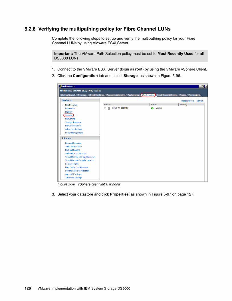
5.2.8 Verifying the multipathing policy for Fibre Channel LUNs
Complete the following steps to set up and verify the multipathing policy for your Fibre Channel LUNs by using VMware ESXi Server:
1. Connect to the VMware ESXi Server (login as root) by using the VMware vSphere Client.
2. Click the Configuration tab and select Storage, as shown in Figure 5-96.
Figure 5-96 vSphere client initial window
3. Select your datastore and click Properties, as shown in Figure 5-97 on page 127.
Important: The VMware Path Selection policy must be set to Most Recently Used for all DS5000 LUNs.
126 VMware Implementation with IBM System Storage DS5000
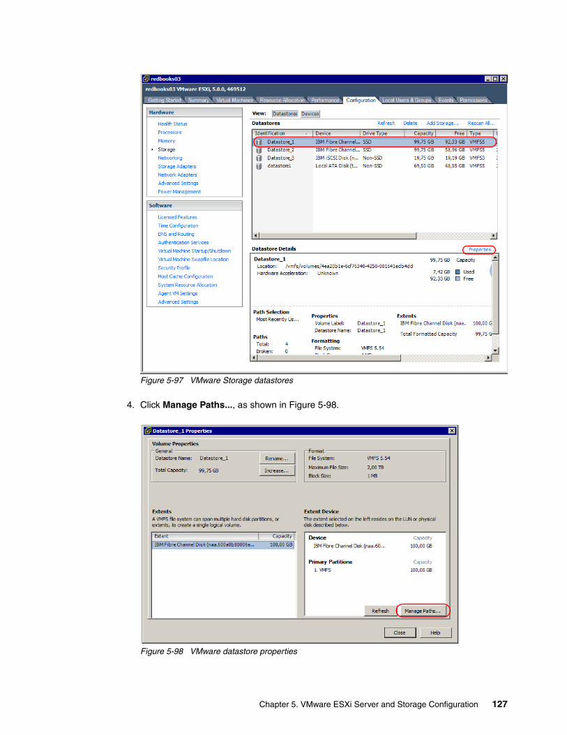
Figure 5-97 VMware Storage datastores
4. Click Manage Paths..., as shown in Figure 5-98.
Figure 5-98 VMware datastore properties
Chapter 5. VMware ESXi Server and Storage Configuration 127
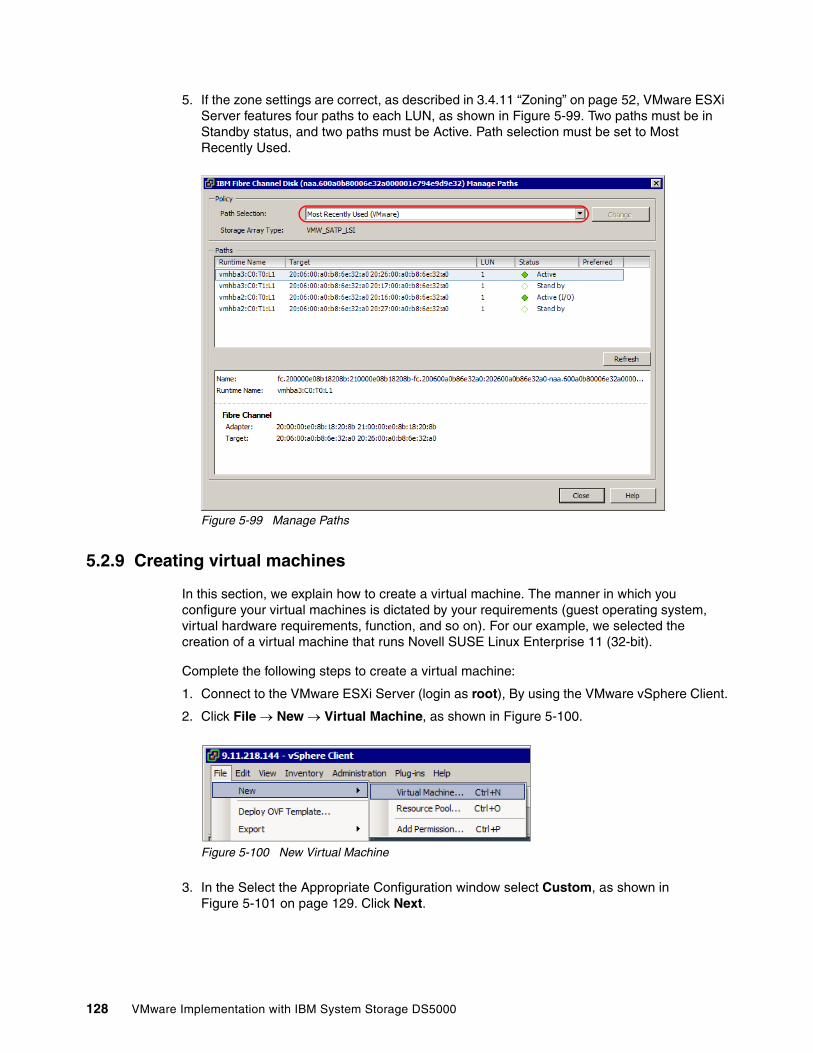
5. If the zone settings are correct, as described in 3.4.11 “Zoning” on page 52, VMware ESXi Server features four paths to each LUN, as shown in Figure 5-99. Two paths must be in Standby status, and two paths must be Active. Path selection must be set to Most Recently Used.
Figure 5-99 Manage Paths
5.2.9 Creating virtual machines
In this section, we explain how to create a virtual machine. The manner in which you configure your virtual machines is dictated by your requirements (guest operating system, virtual hardware requirements, function, and so on). For our example, we selected the creation of a virtual machine that runs Novell SUSE Linux Enterprise 11 (32-bit).
Complete the following steps to create a virtual machine:
1. Connect to the VMware ESXi Server (login as root), By using the VMware vSphere Client.
2. Click File New Virtual Machine, as shown in Figure 5-100.
Figure 5-100 New Virtual Machine
3. In the Select the Appropriate Configuration window select Custom, as shown in Figure 5-101 on page 129. Click Next.
128 VMware Implementation with IBM System Storage DS5000

Figure 5-101 Configuration Type
4. In the Virtual Machine Name field, enter the name of the virtual machine, as shown in Figure 5-102 on page 130. Click Next.
Chapter 5. VMware ESXi Server and Storage Configuration 129
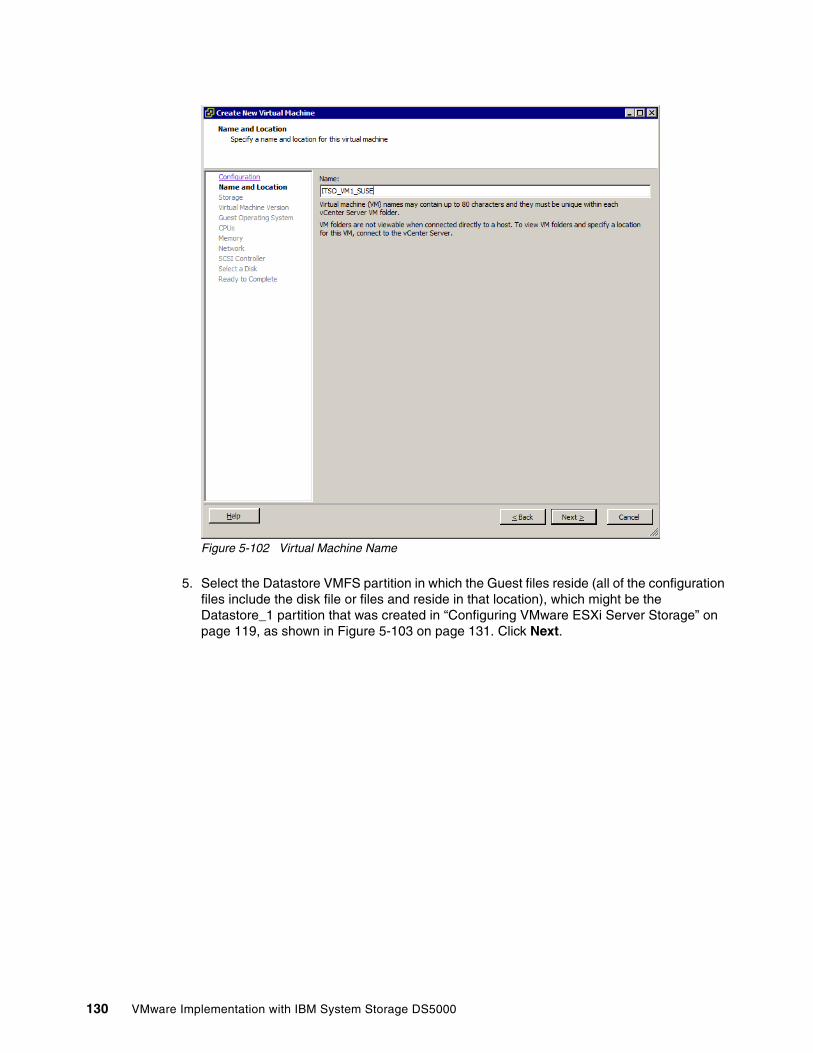
Figure 5-102 Virtual Machine Name
5. Select the Datastore VMFS partition in which the Guest files reside (all of the configuration files include the disk file or files and reside in that location), which might be the Datastore_1 partition that was created in “Configuring VMware ESXi Server Storage” on page 119, as shown in Figure 5-103 on page 131. Click Next.
130 VMware Implementation with IBM System Storage DS5000
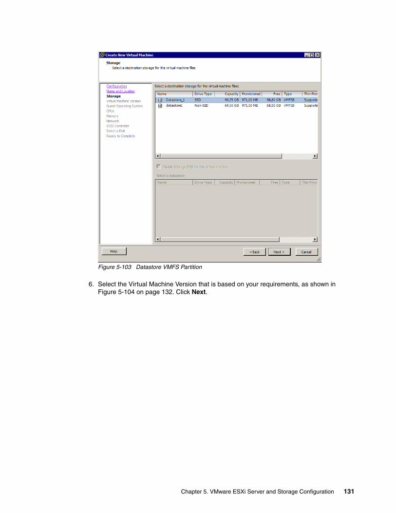
Figure 5-103 Datastore VMFS Partition
6. Select the Virtual Machine Version that is based on your requirements, as shown in Figure 5-104 on page 132. Click Next.
Chapter 5. VMware ESXi Server and Storage Configuration 131
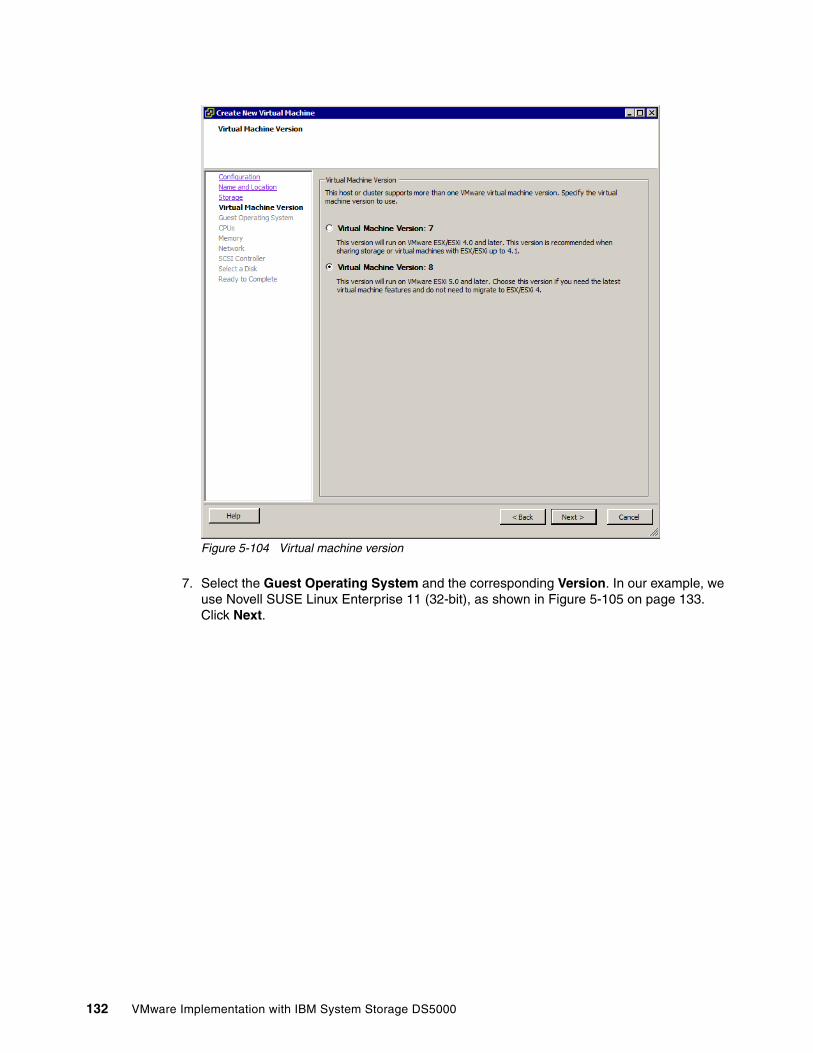
Figure 5-104 Virtual machine version
7. Select the Guest Operating System and the corresponding Version. In our example, we use Novell SUSE Linux Enterprise 11 (32-bit), as shown in Figure 5-105 on page 133. Click Next.
132 VMware Implementation with IBM System Storage DS5000
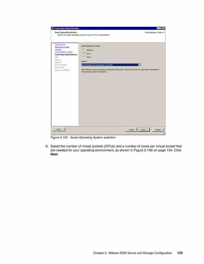
Figure 5-105 Guest Operating System selection
8. Select the number of virtual sockets (CPUs) and a number of cores per virtual socket that are needed for your operating environment, as shown in Figure 5-106 on page 134. Click Next.
Chapter 5. VMware ESXi Server and Storage Configuration 133
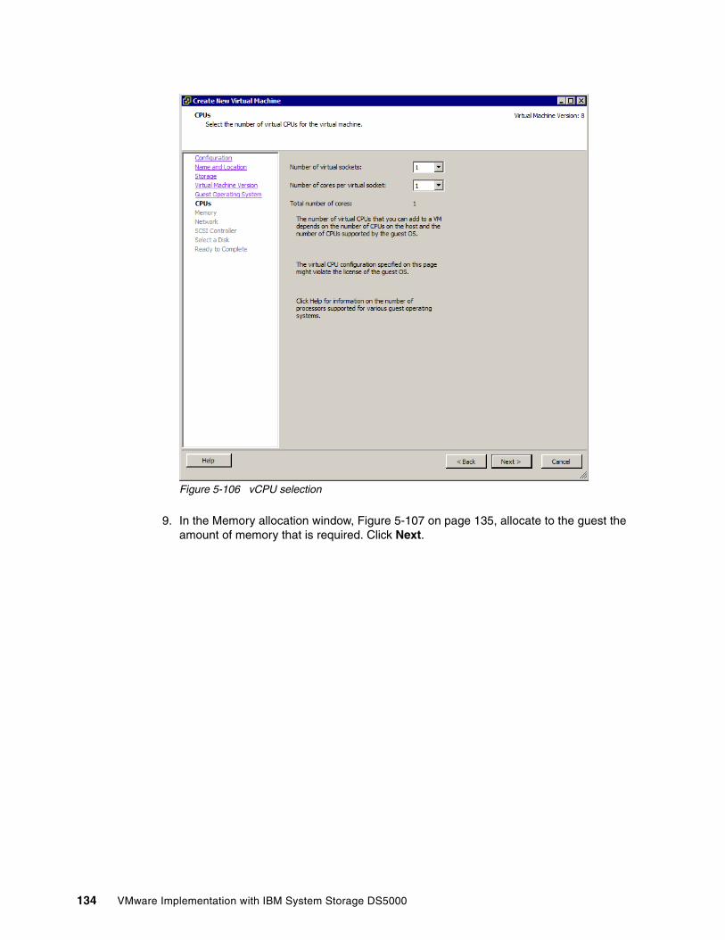
Figure 5-106 vCPU selection
9. In the Memory allocation window, Figure 5-107 on page 135, allocate to the guest the amount of memory that is required. Click Next.
134 VMware Implementation with IBM System Storage DS5000
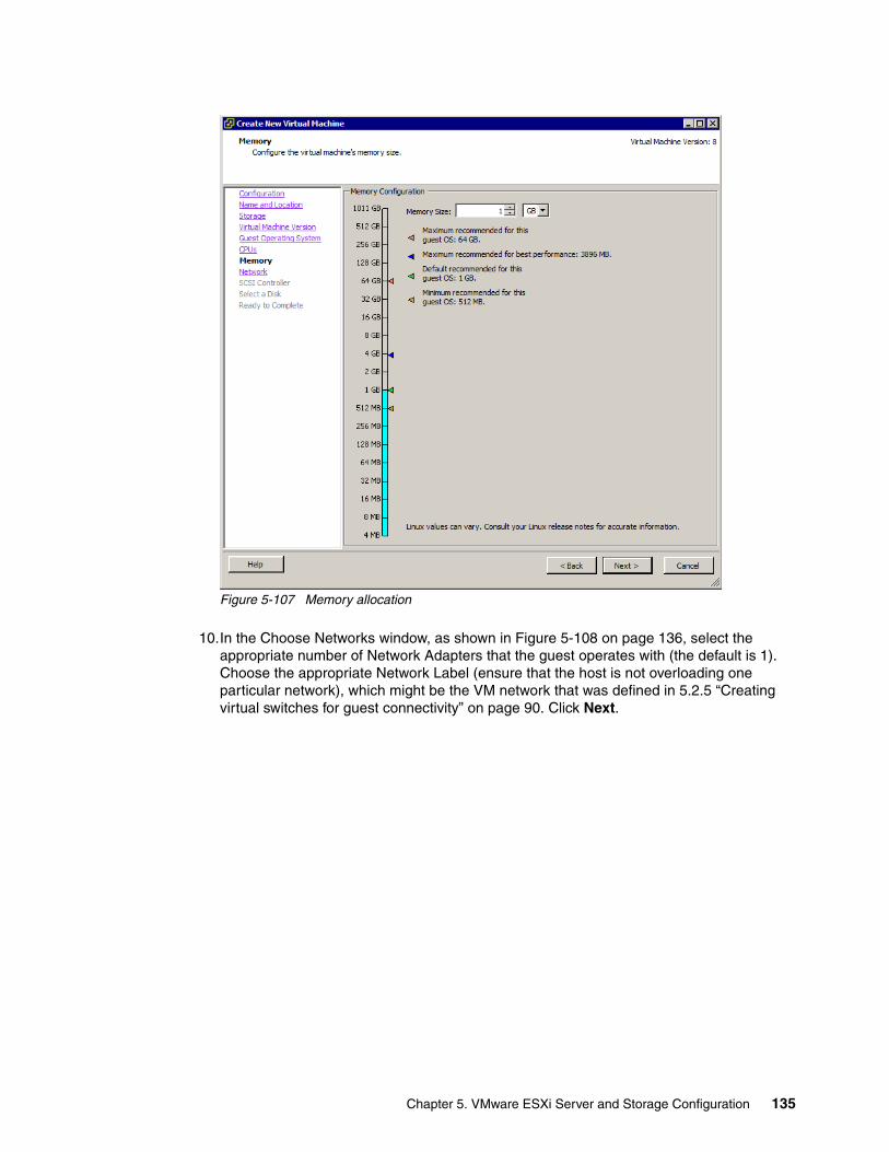
Figure 5-107 Memory allocation
10.In the Choose Networks window, as shown in Figure 5-108 on page 136, select the appropriate number of Network Adapters that the guest operates with (the default is 1). Choose the appropriate Network Label (ensure that the host is not overloading one particular network), which might be the VM network that was defined in 5.2.5 “Creating virtual switches for guest connectivity” on page 90. Click Next.
Chapter 5. VMware ESXi Server and Storage Configuration 135
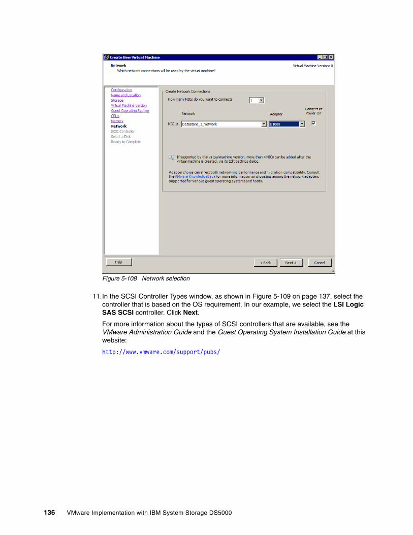
Figure 5-108 Network selection
11.In the SCSI Controller Types window, as shown in Figure 5-109 on page 137, select the controller that is based on the OS requirement. In our example, we select the LSI Logic SAS SCSI controller. Click Next.
For more information about the types of SCSI controllers that are available, see the VMware Administration Guide and the Guest Operating System Installation Guide at this website:
http://www.vmware.com/support/pubs/
136 VMware Implementation with IBM System Storage DS5000
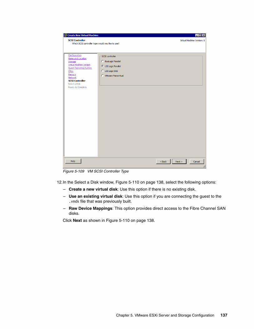
Figure 5-109 VM SCSI Controller Type
12.In the Select a Disk window, Figure 5-110 on page 138, select the following options:
– Create a new virtual disk: Use this option if there is no existing disk.
– Use an existing virtual disk: Use this option if you are connecting the guest to the .vmdk file that was previously built.
– Raw Device Mappings: This option provides direct access to the Fibre Channel SAN disks.
Click Next as shown in Figure 5-110 on page 138.
Chapter 5. VMware ESXi Server and Storage Configuration 137
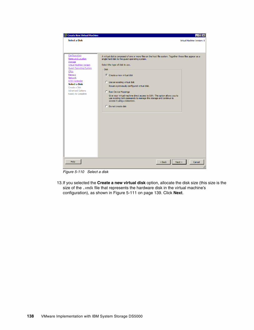
Figure 5-110 Select a disk
13.If you selected the Create a new virtual disk option, allocate the disk size (this size is the size of the .vmdk file that represents the hardware disk in the virtual machine’s configuration), as shown in Figure 5-111 on page 139. Click Next.
138 VMware Implementation with IBM System Storage DS5000
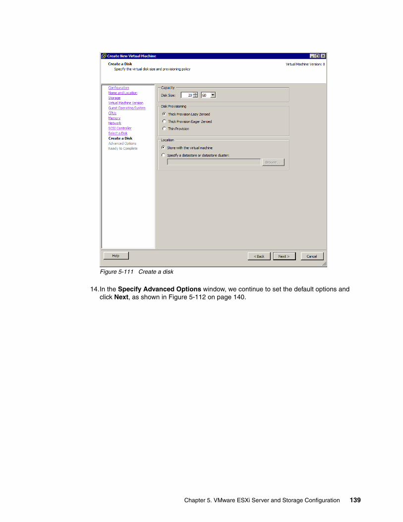
Figure 5-111 Create a disk
14.In the Specify Advanced Options window, we continue to set the default options and click Next, as shown in Figure 5-112 on page 140.
Chapter 5. VMware ESXi Server and Storage Configuration 139
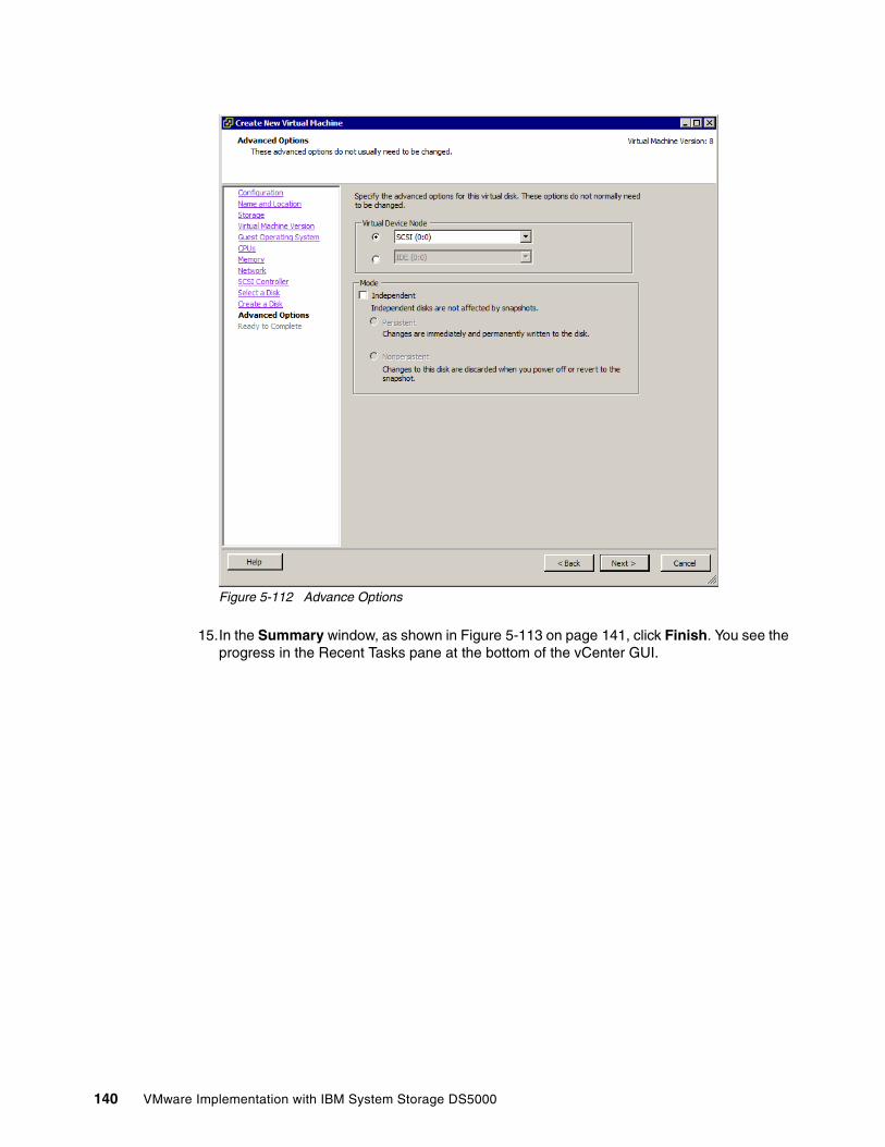
Figure 5-112 Advance Options
15.In the Summary window, as shown in Figure 5-113 on page 141, click Finish. You see the progress in the Recent Tasks pane at the bottom of the vCenter GUI.
140 VMware Implementation with IBM System Storage DS5000
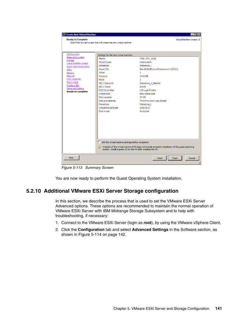
Figure 5-113 Summary Screen
You are now ready to perform the Guest Operating System installation.
5.2.10 Additional VMware ESXi Server Storage configuration
In this section, we describe the process that is used to set the VMware ESXi Server Advanced options. These options are recommended to maintain the normal operation of VMware ESXi Server with IBM Midrange Storage Subsystem and to help with troubleshooting, if necessary:
1. Connect to the VMware ESXi Server (login as root), by using the VMware vSphere Client,
2. Click the Configuration tab and select Advanced Settings in the Software section, as shown in Figure 5-114 on page 142.
Chapter 5. VMware ESXi Server and Storage Configuration 141
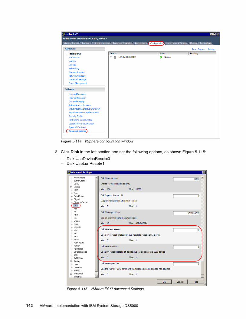
Figure 5-114 VSphere configuration window
3. Click Disk in the left section and set the following options, as shown Figure 5-115:
– Disk.UseDeviceReset=0– Disk.UseLunReset=1
Figure 5-115 VMware ESXi Advanced Settings
142 VMware Implementation with IBM System Storage DS5000
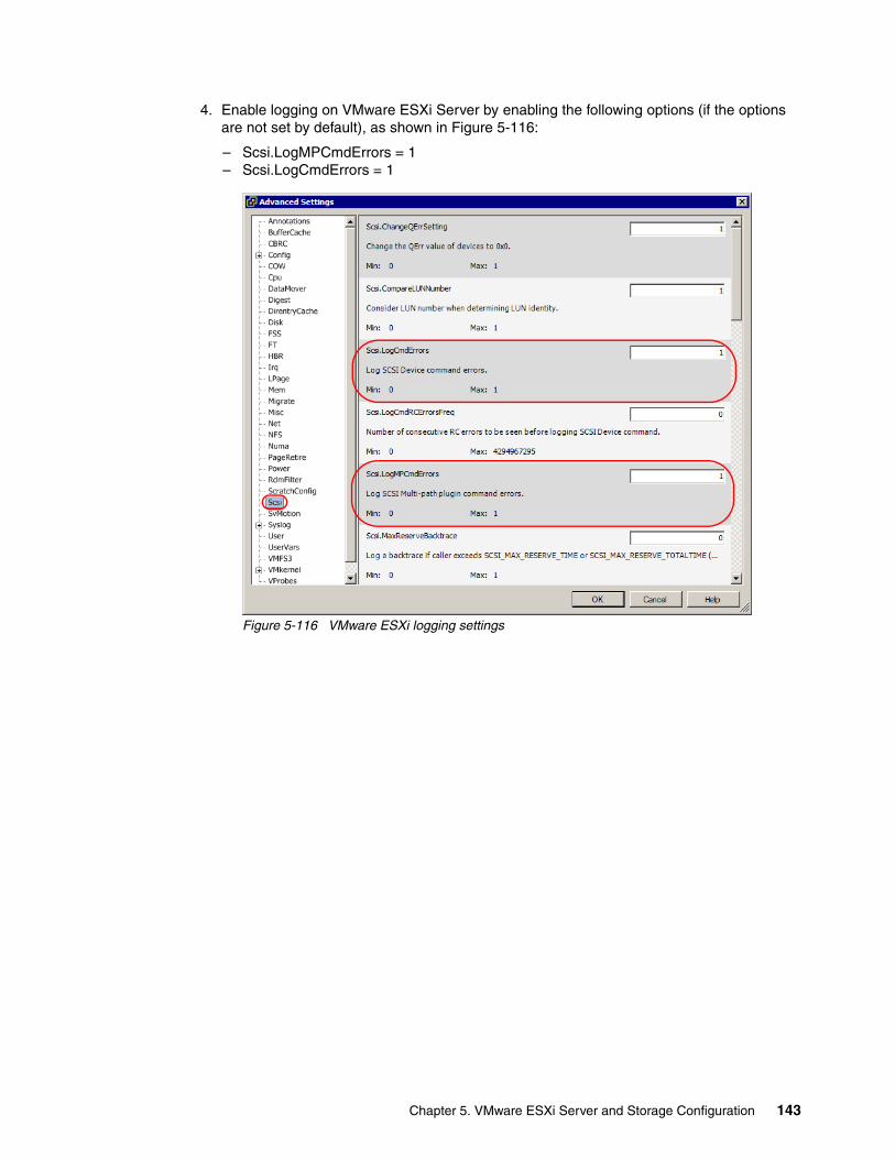
4. Enable logging on VMware ESXi Server by enabling the following options (if the options are not set by default), as shown in Figure 5-116:
– Scsi.LogMPCmdErrors = 1– Scsi.LogCmdErrors = 1
Figure 5-116 VMware ESXi logging settings
Chapter 5. VMware ESXi Server and Storage Configuration 143

144 VMware Implementation with IBM System Storage DS5000
Chapter 6. VMware Command Line Tools for Configuring vSphere ESXi Storage
In this chapter, we describe the basic process that is used for configuring SAN attach storage by using iSCSI Software Initiator and Fibre Channel protocol. We also describe the settings that are used to connect to DS5000 storage subsystems.
6
© Copyright IBM Corp. 2012. All rights reserved. 145
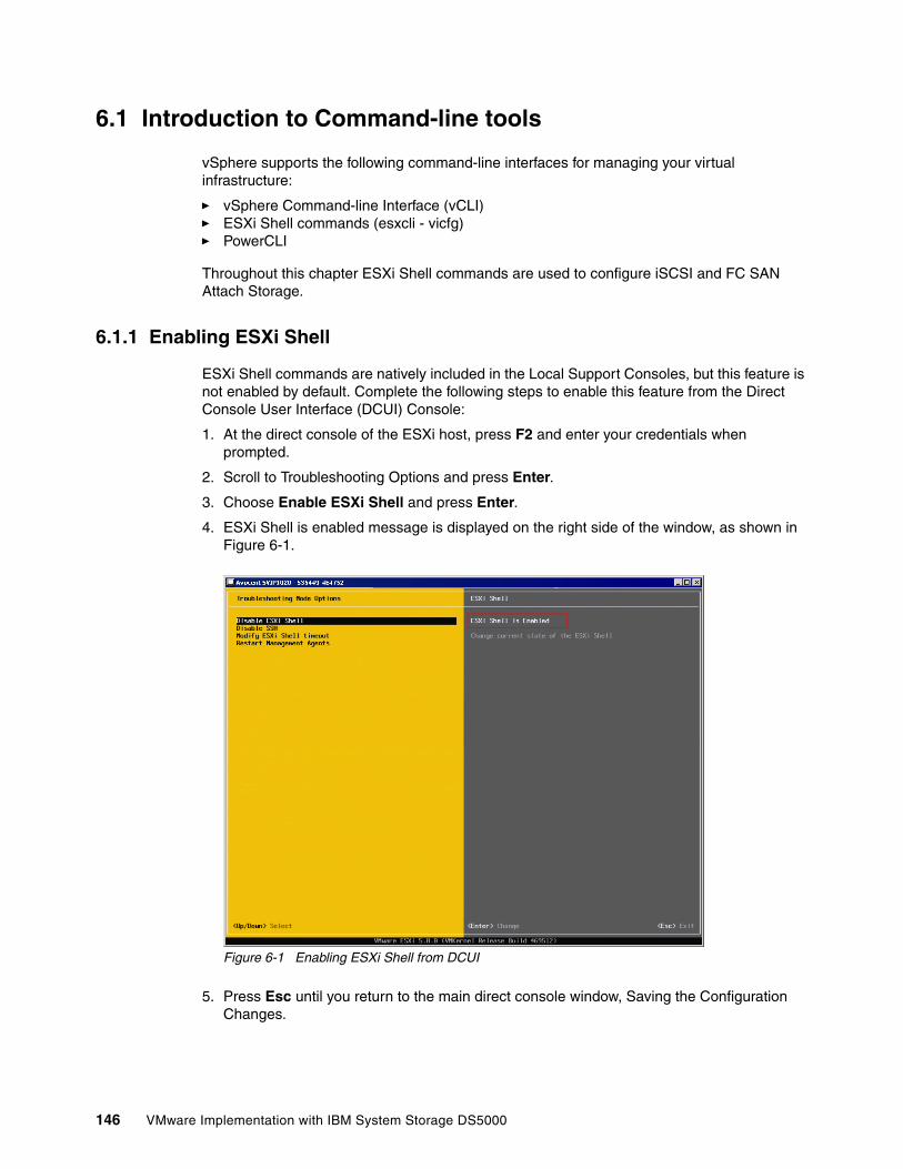
6.1 Introduction to Command-line tools
vSphere supports the following command-line interfaces for managing your virtual infrastructure:
� vSphere Command-line Interface (vCLI) � ESXi Shell commands (esxcli - vicfg)� PowerCLI
Throughout this chapter ESXi Shell commands are used to configure iSCSI and FC SAN Attach Storage.
6.1.1 Enabling ESXi Shell
ESXi Shell commands are natively included in the Local Support Consoles, but this feature is not enabled by default. Complete the following steps to enable this feature from the Direct Console User Interface (DCUI) Console:
1. At the direct console of the ESXi host, press F2 and enter your credentials when prompted.
2. Scroll to Troubleshooting Options and press Enter.
3. Choose Enable ESXi Shell and press Enter.
4. ESXi Shell is enabled message is displayed on the right side of the window, as shown in Figure 6-1.
Figure 6-1 Enabling ESXi Shell from DCUI
5. Press Esc until you return to the main direct console window, Saving the Configuration Changes.
146 VMware Implementation with IBM System Storage DS5000
6.1.2 Running ESXi Shell Commands
vSphere ESXi supports the execution of ESXi Shell commands from the following ways:
� Locally executed from the DCUI console� Remotely executed by using SSH through the local support console� Remotely by using vMA appliance� Remotely by using vSphere CLI
For this example, we run ESXi Shell commands remotely by using vSphere CLI. We install the vSphere CLI command set on a supported Linux or Windows system. The installation package and deployment procedure are available at this website:
http://www.vmware.com/support/developer/vcli/
By default, vSphere CLI command is on: Start Programs VMware VMware vSphere CLI
The basic usage of the command is shown in the following example:
esxcli --server <vc_server> --username <privileged_user> --password <pw> --vihost <esx<namespace> [<namespace]...> <command> --<option_name=option_value>
Later in this chapter, we describe the basic command-line syntax. For more information about ESXi Shell commands, see this website:
http://pubs.vmware.com/vsphere-50/topic/com.vmware.vcli.getstart.doc_50/cli_about.html
6.1.3 Saving time by running ESXi Shell commands
To avoid redundancy when the connection information is added on the command line, we create a connection document that is used when you run a command.
The contents of the configuration file that was saved as esxcli.config is shown in the following example:
VI_SERVER = XX.XXX.XXX.XXVI_USERNAME = rootVI_PASSWORD = my_passwordVI_PROTOCOL = httpsVI_PORTNUMBER = 443
Replacing this information with your environment data results in a useful tool that is used to run ESXi Shell commands.
Important: Save the configuration file in the same location or path as is used for your ESXi Shell command to avoid syntax errors. The following default locations of ESXi Shell command in Windows operating system (OS) are:
� 32-bit OS: C:\Program Files\VMware\VMware vSphere CLI\� 64-bit OS: C:\Program Files (x86)\VMware\VMware vSphere CLI\
Chapter 6. VMware Command Line Tools for Configuring vSphere ESXi Storage 147
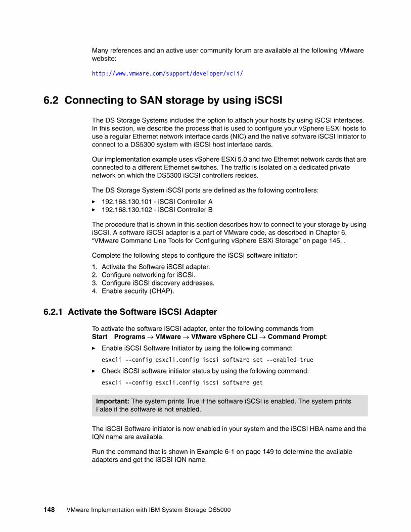
Many references and an active user community forum are available at the following VMware website:
http://www.vmware.com/support/developer/vcli/
6.2 Connecting to SAN storage by using iSCSI
The DS Storage Systems includes the option to attach your hosts by using iSCSI interfaces. In this section, we describe the process that is used to configure your vSphere ESXi hosts to use a regular Ethernet network interface cards (NIC) and the native software iSCSI Initiator to connect to a DS5300 system with iSCSI host interface cards.
Our implementation example uses vSphere ESXi 5.0 and two Ethernet network cards that are connected to a different Ethernet switches. The traffic is isolated on a dedicated private network on which the DS5300 iSCSI controllers resides.
The DS Storage System iSCSI ports are defined as the following controllers:
� 192.168.130.101 - iSCSI Controller A� 192.168.130.102 - iSCSI Controller B
The procedure that is shown in this section describes how to connect to your storage by using iSCSI. A software iSCSI adapter is a part of VMware code, as described in Chapter 6, “VMware Command Line Tools for Configuring vSphere ESXi Storage” on page 145, .
Complete the following steps to configure the iSCSI software initiator:
1. Activate the Software iSCSI adapter.2. Configure networking for iSCSI.3. Configure iSCSI discovery addresses.4. Enable security (CHAP).
6.2.1 Activate the Software iSCSI Adapter
To activate the software iSCSI adapter, enter the following commands from Start Programs VMware VMware vSphere CLI Command Prompt:
� Enable iSCSI Software Initiator by using the following command:
esxcli --config esxcli.config iscsi software set --enabled=true
� Check iSCSI software initiator status by using the following command:
esxcli --config esxcli.config iscsi software get
The iSCSI Software initiator is now enabled in your system and the iSCSI HBA name and the IQN name are available.
Run the command that is shown in Example 6-1 on page 149 to determine the available adapters and get the iSCSI IQN name.
Important: The system prints True if the software iSCSI is enabled. The system prints False if the software is not enabled.
148 VMware Implementation with IBM System Storage DS5000
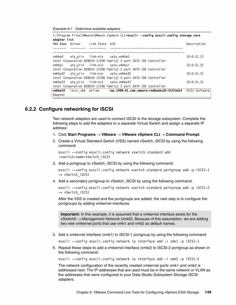
Example 6-1 Determine available adapters
C:\Program Files\VMware\VMware vSphere CLI>esxcli --config esxcli.config storage core adapter listHBA Name Driver Link State UID Description-------- --------- ---------- ------------------------------------------ ----------------------------------------------------------------------------vmhba0 ata_piix link-n/a sata.vmhba0 (0:0:31.2) Intel Corporation 82801H (ICH8 Family) 4 port SATA IDE Controllervmhba1 ata_piix link-n/a sata.vmhba1 (0:0:31.5) Intel Corporation 82801H (ICH8 Family) 2 port SATA IDE Controllervmhba32 ata_piix link-n/a sata.vmhba32 (0:0:31.2) Intel Corporation 82801H (ICH8 Family) 4 port SATA IDE Controllervmhba33 ata_piix link-n/a sata.vmhba33 (0:0:31.5) Intel Corporation 82801H (ICH8 Family) 2 port SATA IDE Controllervmhba34 iscsi_vmk online iqn.1998-01.com.vmware:redbooks03-5147ed14 iSCSI Software Adapter
6.2.2 Configure networking for iSCSI
Two network adapters are used to connect iSCSI to the storage subsystem. Complete the following steps to add the adapters to a separate Virtual Switch and assign a separate IP address:
1. Click Start Programs VMware VMware vSphere CLI Command Prompt.
2. Create a Virtual Standard Switch (VSS) named vSwitch_iSCSI by using the following command:
esxcli --config esxcli.config network vswitch standard add -vswitch-name=vSwitch_iSCSI
3. Add a portgroup to vSwitch_iSCSI by using the following command:
esxcli --config esxcli.config network vswitch standard portgroup add -p iSCSI-1 -v vSwitch_iSCSI
4. Add a secondary portgroup to vSwitch_iSCSI by using the following command:
esxcli --config esxcli.config network vswitch standard portgroup add -p iSCSI-2 -v vSwitch_iSCSI
After the VSS is created and the portgroups are added, the next step is to configure the portgroups by adding vmkernel interfaces.
5. Add a vmkernel interface (vmk1) to iSCSI-1 portgroup by using the following command:
esxcli --config esxcli.config network ip interface add -i vmk1 -p iSCSI-1
6. Repeat these steps to add a vmkernel interface (vmk2) to iSCSI-2 portgroup as shown in the following command:
esxcli --config esxcli.config network ip interface add -i vmk2 -p iSCSI-2
The network configuration of the recently created vmkernel ports vmk1 and vmk2 is addressed next. The IP addresses that are used must be in the same network or VLAN as the addresses that were configured in your Data Studio Subsystem Storage iSCSI adapters.
Important: In this example, it is assumed that a vmkernel interface exists for the vSwitch0 Management Network (vmk0). Because of this assumption, we are adding two new vmkernel ports that use vmk1 and vmk2 as default names.
Chapter 6. VMware Command Line Tools for Configuring vSphere ESXi Storage 149
7. Set the static IP addresses on both VMkernel NICs as part of the iSCSI network by using the following command:
esxcli --config esxcli.config network ip interface ipv4 set -i vmk1 -I 192.168.130.50 -N 255.255.255.0 -t static
8. Configure the secondary VMkernel interface vmk2 by using the following command:
esxcli --config esxcli.config network ip interface ipv4 set -i vmk2 -I 192.168.130.51 -N 255.255.255.0 -t static
Complete the following steps to add Uplinks to the vSwitch_iSCSI virtual switch:
9. Add a primary Uplink adapter by using the following command:
esxcli --config esxcli.config network vswitch standard uplink add --uplink-name=vmnic1 --vswitch-name=vSwitch_iSCSI
10.Add a secondary Uplink adapter by using the following command:
esxcli --config esxcli.config network vswitch standard uplink add --uplink-name=vmnic2 --vswitch-name=vSwitch_iSCSI
11.Set the manual override fail-over policy so that each iSCSI VMkernel portgroup includes one active physical vmnic and one vmnic that is configured as unused.
12.Change the default failover policy for the iSCSI-1 port group by using the following command:
esxcli --config esxcli.config network vswitch standard portgroup policy failover set -p iSCSI-1 -a vmnic1 -u vmnic2
13.Change the default failover policy for iSCSI-2 port group by using the following command:
esxcli --config esxcli.config network vswitch standard portgroup policy failover set -p iSCSI-2 -a vmnic2 -u vmnic1
14.Configure the policy failover at Virtual Switch level by using the following command:
esxcli --config esxcli.config network vswitch standard policy failover set -v vSwitch_iSCSI -a vmnic1,vmnic2
A Virtual Switch is created. To check the vSwitch configuration parameters, run the command line that is shown in Example 6-2 on page 151.
Important: Use the following command to check the available vmnics:
esxcli --config esxcli.config network nic list
150 VMware Implementation with IBM System Storage DS5000
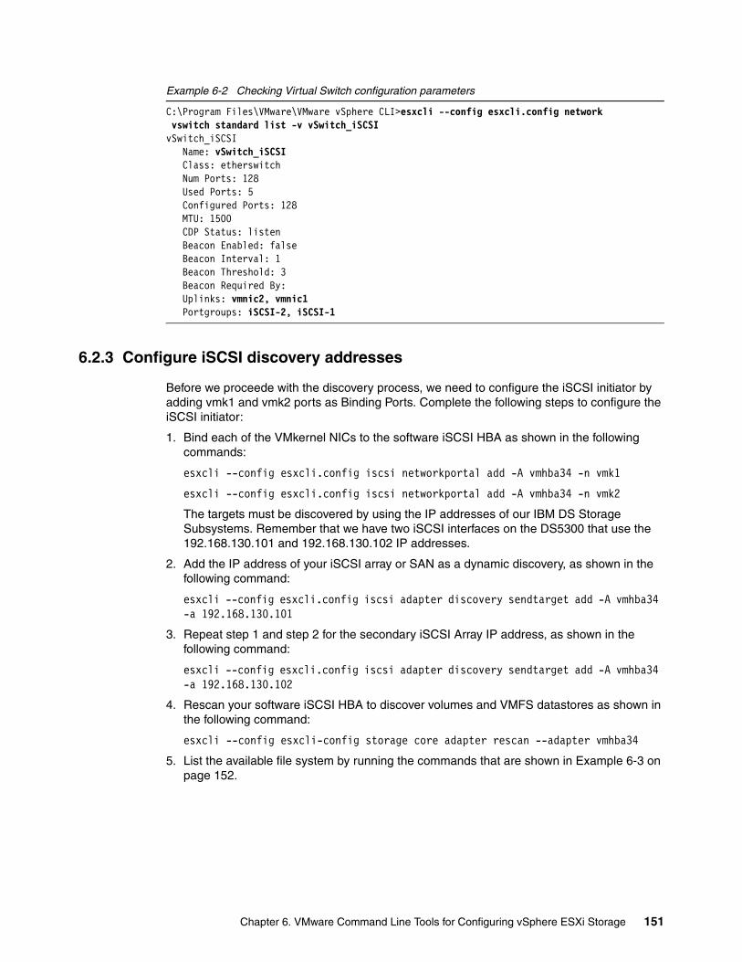
Example 6-2 Checking Virtual Switch configuration parameters
C:\Program Files\VMware\VMware vSphere CLI>esxcli --config esxcli.config network vswitch standard list -v vSwitch_iSCSIvSwitch_iSCSI Name: vSwitch_iSCSI Class: etherswitch Num Ports: 128 Used Ports: 5 Configured Ports: 128 MTU: 1500 CDP Status: listen Beacon Enabled: false Beacon Interval: 1 Beacon Threshold: 3 Beacon Required By: Uplinks: vmnic2, vmnic1 Portgroups: iSCSI-2, iSCSI-1
6.2.3 Configure iSCSI discovery addresses
Before we proceede with the discovery process, we need to configure the iSCSI initiator by adding vmk1 and vmk2 ports as Binding Ports. Complete the following steps to configure the iSCSI initiator:
1. Bind each of the VMkernel NICs to the software iSCSI HBA as shown in the following commands:
esxcli --config esxcli.config iscsi networkportal add -A vmhba34 -n vmk1
esxcli --config esxcli.config iscsi networkportal add -A vmhba34 -n vmk2
The targets must be discovered by using the IP addresses of our IBM DS Storage Subsystems. Remember that we have two iSCSI interfaces on the DS5300 that use the 192.168.130.101 and 192.168.130.102 IP addresses.
2. Add the IP address of your iSCSI array or SAN as a dynamic discovery, as shown in the following command:
esxcli --config esxcli.config iscsi adapter discovery sendtarget add -A vmhba34 -a 192.168.130.101
3. Repeat step 1 and step 2 for the secondary iSCSI Array IP address, as shown in the following command:
esxcli --config esxcli.config iscsi adapter discovery sendtarget add -A vmhba34 -a 192.168.130.102
4. Rescan your software iSCSI HBA to discover volumes and VMFS datastores as shown in the following command:
esxcli --config esxcli-config storage core adapter rescan --adapter vmhba34
5. List the available file system by running the commands that are shown in Example 6-3 on page 152.
Chapter 6. VMware Command Line Tools for Configuring vSphere ESXi Storage 151
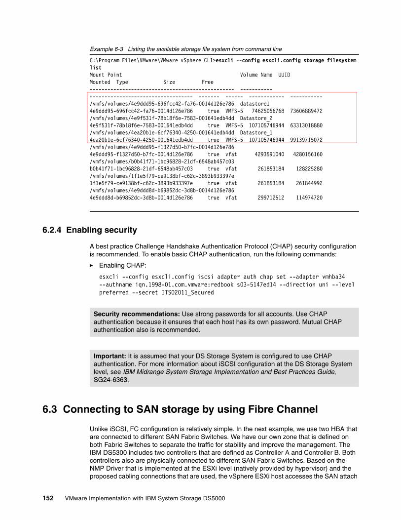
Example 6-3 Listing the available storage file system from command line
C:\Program Files\VMware\VMware vSphere CLI>esxcli --config esxcli.config storage filesystem listMount Point Volume Name UUID Mounted Type Size Free------------------------------------------------- ----------- ----------------------------------- ------- ------ ------------ -----------/vmfs/volumes/4e9ddd95-696fcc42-fa76-0014d126e786 datastore1 4e9ddd95-696fcc42-fa76-0014d126e786 true VMFS-5 74625056768 73606889472/vmfs/volumes/4e9f531f-78b18f6e-7583-001641edb4dd Datastore_2 4e9f531f-78b18f6e-7583-001641edb4dd true VMFS-5 107105746944 63313018880/vmfs/volumes/4ea20b1e-6cf76340-4250-001641edb4dd Datastore_1 4ea20b1e-6cf76340-4250-001641edb4dd true VMFS-5 107105746944 99139715072/vmfs/volumes/4e9ddd95-f1327d50-b7fc-0014d126e786 4e9ddd95-f1327d50-b7fc-0014d126e786 true vfat 4293591040 4280156160/vmfs/volumes/b0b41f71-1bc96828-21df-6548ab457c03 b0b41f71-1bc96828-21df-6548ab457c03 true vfat 261853184 128225280/vmfs/volumes/1f1e5f79-ce9138bf-c62c-3893b933397e 1f1e5f79-ce9138bf-c62c-3893b933397e true vfat 261853184 261844992/vmfs/volumes/4e9ddd8d-b69852dc-3d8b-0014d126e786 4e9ddd8d-b69852dc-3d8b-0014d126e786 true vfat 299712512 114974720
6.2.4 Enabling security
A best practice Challenge Handshake Authentication Protocol (CHAP) security configuration is recommended. To enable basic CHAP authentication, run the following commands:
� Enabling CHAP:
esxcli --config esxcli.config iscsi adapter auth chap set --adapter vmhba34 --authname iqn.1998-01.com.vmware:redbook s03-5147ed14 --direction uni --level preferred --secret ITSO2011_Secured
6.3 Connecting to SAN storage by using Fibre Channel
Unlike iSCSI, FC configuration is relatively simple. In the next example, we use two HBA that are connected to different SAN Fabric Switches. We have our own zone that is defined on both Fabric Switches to separate the traffic for stability and improve the management. The IBM DS5300 includes two controllers that are defined as Controller A and Controller B. Both controllers also are physically connected to different SAN Fabric Switches. Based on the NMP Driver that is implemented at the ESXi level (natively provided by hypervisor) and the proposed cabling connections that are used, the vSphere ESXi host accesses the SAN attach
Security recommendations: Use strong passwords for all accounts. Use CHAP authentication because it ensures that each host has its own password. Mutual CHAP authentication also is recommended.
Important: It is assumed that your DS Storage System is configured to use CHAP authentication. For more information about iSCSI configuration at the DS Storage System level, see IBM Midrange System Storage Implementation and Best Practices Guide, SG24-6363.
152 VMware Implementation with IBM System Storage DS5000
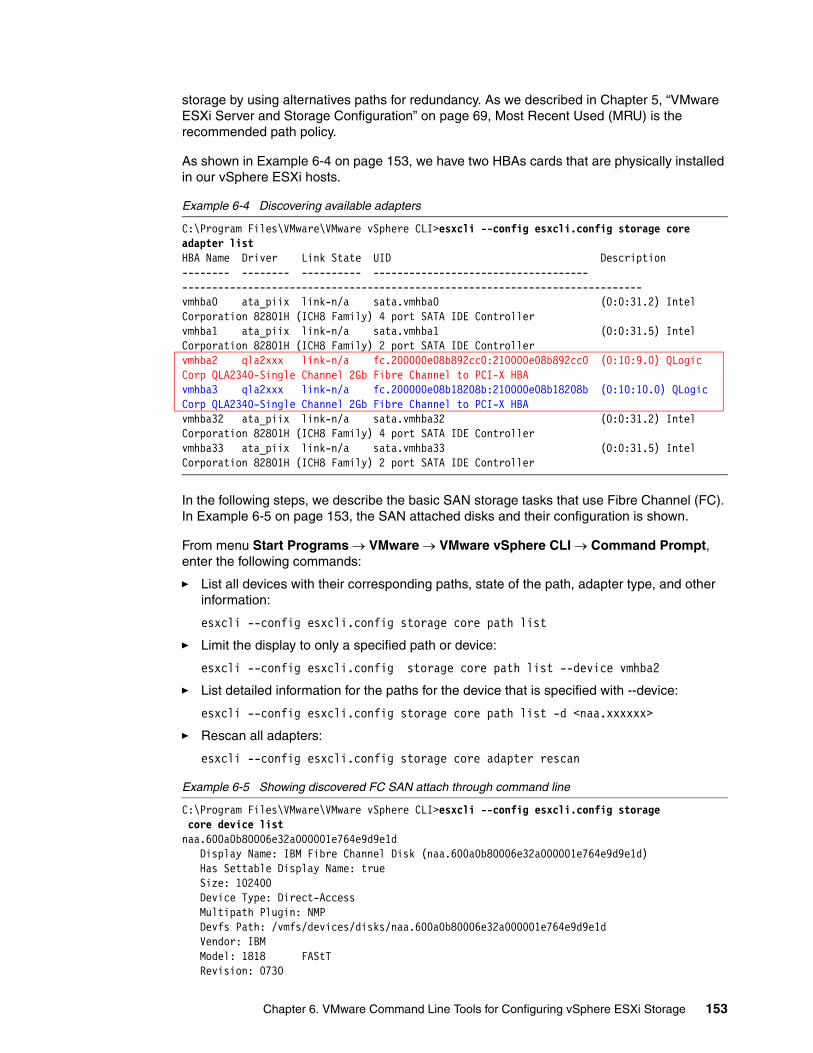
storage by using alternatives paths for redundancy. As we described in Chapter 5, “VMware ESXi Server and Storage Configuration” on page 69, Most Recent Used (MRU) is the recommended path policy.
As shown in Example 6-4 on page 153, we have two HBAs cards that are physically installed in our vSphere ESXi hosts.
Example 6-4 Discovering available adapters
C:\Program Files\VMware\VMware vSphere CLI>esxcli --config esxcli.config storage core adapter listHBA Name Driver Link State UID Description-------- -------- ---------- ------------------------------------ -----------------------------------------------------------------------------vmhba0 ata_piix link-n/a sata.vmhba0 (0:0:31.2) Intel Corporation 82801H (ICH8 Family) 4 port SATA IDE Controllervmhba1 ata_piix link-n/a sata.vmhba1 (0:0:31.5) Intel Corporation 82801H (ICH8 Family) 2 port SATA IDE Controllervmhba2 qla2xxx link-n/a fc.200000e08b892cc0:210000e08b892cc0 (0:10:9.0) QLogic Corp QLA2340-Single Channel 2Gb Fibre Channel to PCI-X HBAvmhba3 qla2xxx link-n/a fc.200000e08b18208b:210000e08b18208b (0:10:10.0) QLogic Corp QLA2340-Single Channel 2Gb Fibre Channel to PCI-X HBAvmhba32 ata_piix link-n/a sata.vmhba32 (0:0:31.2) Intel Corporation 82801H (ICH8 Family) 4 port SATA IDE Controllervmhba33 ata_piix link-n/a sata.vmhba33 (0:0:31.5) Intel Corporation 82801H (ICH8 Family) 2 port SATA IDE Controller
In the following steps, we describe the basic SAN storage tasks that use Fibre Channel (FC). In Example 6-5 on page 153, the SAN attached disks and their configuration is shown.
From menu Start Programs VMware VMware vSphere CLI Command Prompt, enter the following commands:
� List all devices with their corresponding paths, state of the path, adapter type, and other information:
esxcli --config esxcli.config storage core path list
� Limit the display to only a specified path or device:
esxcli --config esxcli.config storage core path list --device vmhba2
� List detailed information for the paths for the device that is specified with --device:
esxcli --config esxcli.config storage core path list -d <naa.xxxxxx>
� Rescan all adapters:
esxcli --config esxcli.config storage core adapter rescan
Example 6-5 Showing discovered FC SAN attach through command line
C:\Program Files\VMware\VMware vSphere CLI>esxcli --config esxcli.config storage core device listnaa.600a0b80006e32a000001e764e9d9e1d Display Name: IBM Fibre Channel Disk (naa.600a0b80006e32a000001e764e9d9e1d) Has Settable Display Name: true Size: 102400 Device Type: Direct-Access Multipath Plugin: NMP Devfs Path: /vmfs/devices/disks/naa.600a0b80006e32a000001e764e9d9e1d Vendor: IBM Model: 1818 FAStT Revision: 0730
Chapter 6. VMware Command Line Tools for Configuring vSphere ESXi Storage 153
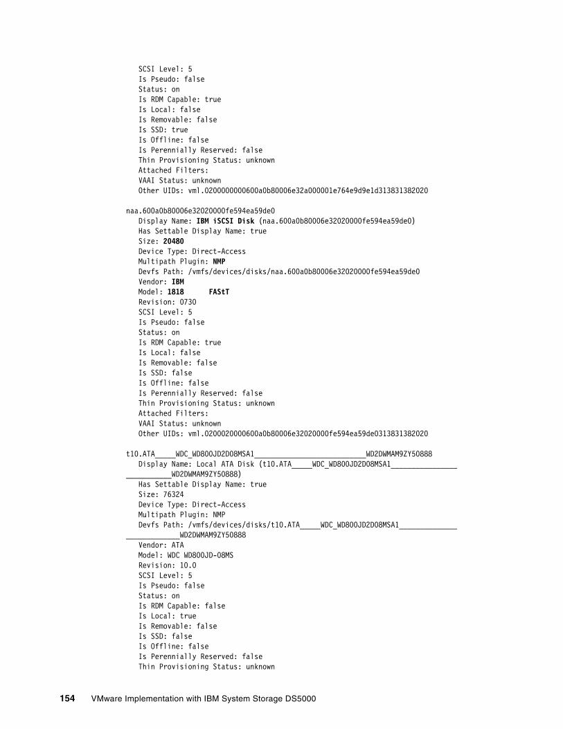
SCSI Level: 5 Is Pseudo: false Status: on Is RDM Capable: true Is Local: false Is Removable: false Is SSD: true Is Offline: false Is Perennially Reserved: false Thin Provisioning Status: unknown Attached Filters: VAAI Status: unknown Other UIDs: vml.0200000000600a0b80006e32a000001e764e9d9e1d313831382020
naa.600a0b80006e32020000fe594ea59de0 Display Name: IBM iSCSI Disk (naa.600a0b80006e32020000fe594ea59de0) Has Settable Display Name: true Size: 20480 Device Type: Direct-Access Multipath Plugin: NMP Devfs Path: /vmfs/devices/disks/naa.600a0b80006e32020000fe594ea59de0 Vendor: IBM Model: 1818 FAStT Revision: 0730 SCSI Level: 5 Is Pseudo: false Status: on Is RDM Capable: true Is Local: false Is Removable: false Is SSD: false Is Offline: false Is Perennially Reserved: false Thin Provisioning Status: unknown Attached Filters: VAAI Status: unknown Other UIDs: vml.0200020000600a0b80006e32020000fe594ea59de0313831382020
t10.ATA_____WDC_WD800JD2D08MSA1___________________________WD2DWMAM9ZY50888 Display Name: Local ATA Disk (t10.ATA_____WDC_WD800JD2D08MSA1___________________________WD2DWMAM9ZY50888) Has Settable Display Name: true Size: 76324 Device Type: Direct-Access Multipath Plugin: NMP Devfs Path: /vmfs/devices/disks/t10.ATA_____WDC_WD800JD2D08MSA1___________________________WD2DWMAM9ZY50888 Vendor: ATA Model: WDC WD800JD-08MS Revision: 10.0 SCSI Level: 5 Is Pseudo: false Status: on Is RDM Capable: false Is Local: true Is Removable: false Is SSD: false Is Offline: false Is Perennially Reserved: false Thin Provisioning Status: unknown
154 VMware Implementation with IBM System Storage DS5000
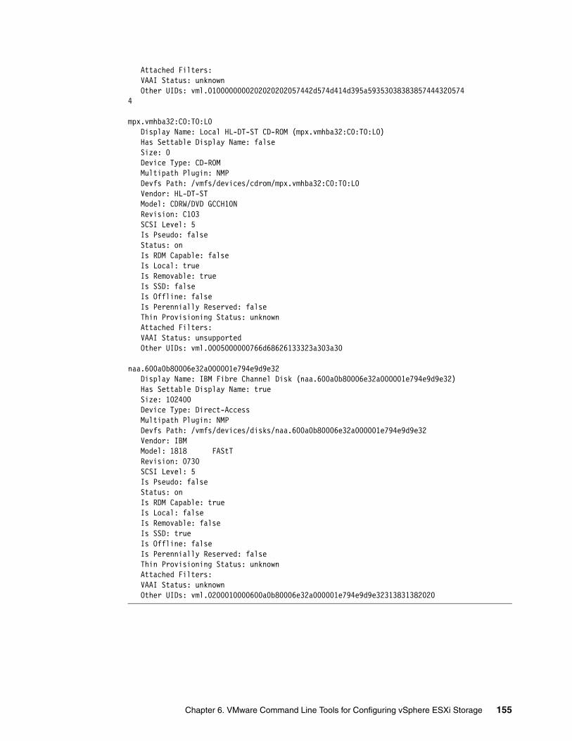
Attached Filters: VAAI Status: unknown Other UIDs: vml.0100000000202020202057442d574d414d395a593530383838574443205744
mpx.vmhba32:C0:T0:L0 Display Name: Local HL-DT-ST CD-ROM (mpx.vmhba32:C0:T0:L0) Has Settable Display Name: false Size: 0 Device Type: CD-ROM Multipath Plugin: NMP Devfs Path: /vmfs/devices/cdrom/mpx.vmhba32:C0:T0:L0 Vendor: HL-DT-ST Model: CDRW/DVD GCCH10N Revision: C103 SCSI Level: 5 Is Pseudo: false Status: on Is RDM Capable: false Is Local: true Is Removable: true Is SSD: false Is Offline: false Is Perennially Reserved: false Thin Provisioning Status: unknown Attached Filters: VAAI Status: unsupported Other UIDs: vml.0005000000766d68626133323a303a30
naa.600a0b80006e32a000001e794e9d9e32 Display Name: IBM Fibre Channel Disk (naa.600a0b80006e32a000001e794e9d9e32) Has Settable Display Name: true Size: 102400 Device Type: Direct-Access Multipath Plugin: NMP Devfs Path: /vmfs/devices/disks/naa.600a0b80006e32a000001e794e9d9e32 Vendor: IBM Model: 1818 FAStT Revision: 0730 SCSI Level: 5 Is Pseudo: false Status: on Is RDM Capable: true Is Local: false Is Removable: false Is SSD: true Is Offline: false Is Perennially Reserved: false Thin Provisioning Status: unknown Attached Filters: VAAI Status: unknown Other UIDs: vml.0200010000600a0b80006e32a000001e794e9d9e32313831382020
Chapter 6. VMware Command Line Tools for Configuring vSphere ESXi Storage 155
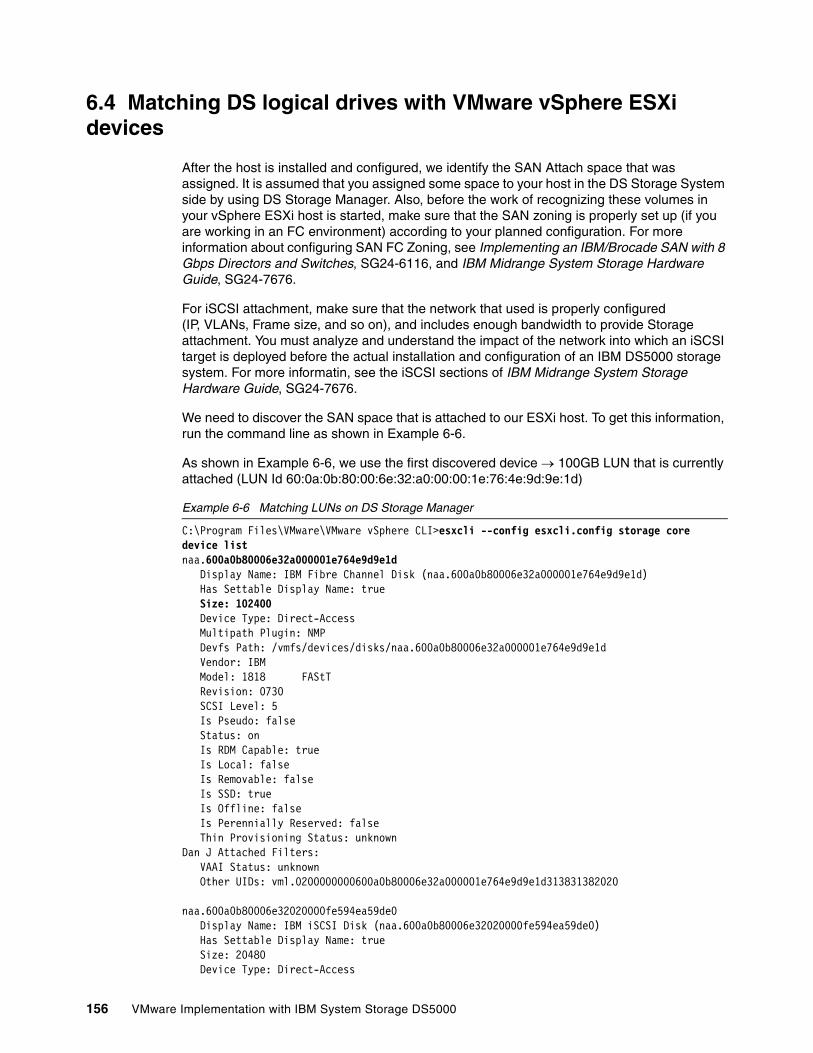
6.4 Matching DS logical drives with VMware vSphere ESXi devices
After the host is installed and configured, we identify the SAN Attach space that was assigned. It is assumed that you assigned some space to your host in the DS Storage System side by using DS Storage Manager. Also, before the work of recognizing these volumes in your vSphere ESXi host is started, make sure that the SAN zoning is properly set up (if you are working in an FC environment) according to your planned configuration. For more information about configuring SAN FC Zoning, see Implementing an IBM/Brocade SAN with 8 Gbps Directors and Switches, SG24-6116, and IBM Midrange System Storage Hardware Guide, SG24-7676.
For iSCSI attachment, make sure that the network that used is properly configured (IP, VLANs, Frame size, and so on), and includes enough bandwidth to provide Storage attachment. You must analyze and understand the impact of the network into which an iSCSI target is deployed before the actual installation and configuration of an IBM DS5000 storage system. For more informatin, see the iSCSI sections of IBM Midrange System Storage Hardware Guide, SG24-7676.
We need to discover the SAN space that is attached to our ESXi host. To get this information, run the command line as shown in Example 6-6.
As shown in Example 6-6, we use the first discovered device 100GB LUN that is currently attached (LUN Id 60:0a:0b:80:00:6e:32:a0:00:00:1e:76:4e:9d:9e:1d)
Example 6-6 Matching LUNs on DS Storage Manager
C:\Program Files\VMware\VMware vSphere CLI>esxcli --config esxcli.config storage core device listnaa.600a0b80006e32a000001e764e9d9e1d Display Name: IBM Fibre Channel Disk (naa.600a0b80006e32a000001e764e9d9e1d) Has Settable Display Name: true Size: 102400 Device Type: Direct-Access Multipath Plugin: NMP Devfs Path: /vmfs/devices/disks/naa.600a0b80006e32a000001e764e9d9e1d Vendor: IBM Model: 1818 FAStT Revision: 0730 SCSI Level: 5 Is Pseudo: false Status: on Is RDM Capable: true Is Local: false Is Removable: false Is SSD: true Is Offline: false Is Perennially Reserved: false Thin Provisioning Status: unknownDan J Attached Filters: VAAI Status: unknown Other UIDs: vml.0200000000600a0b80006e32a000001e764e9d9e1d313831382020
naa.600a0b80006e32020000fe594ea59de0 Display Name: IBM iSCSI Disk (naa.600a0b80006e32020000fe594ea59de0) Has Settable Display Name: true Size: 20480 Device Type: Direct-Access
156 VMware Implementation with IBM System Storage DS5000
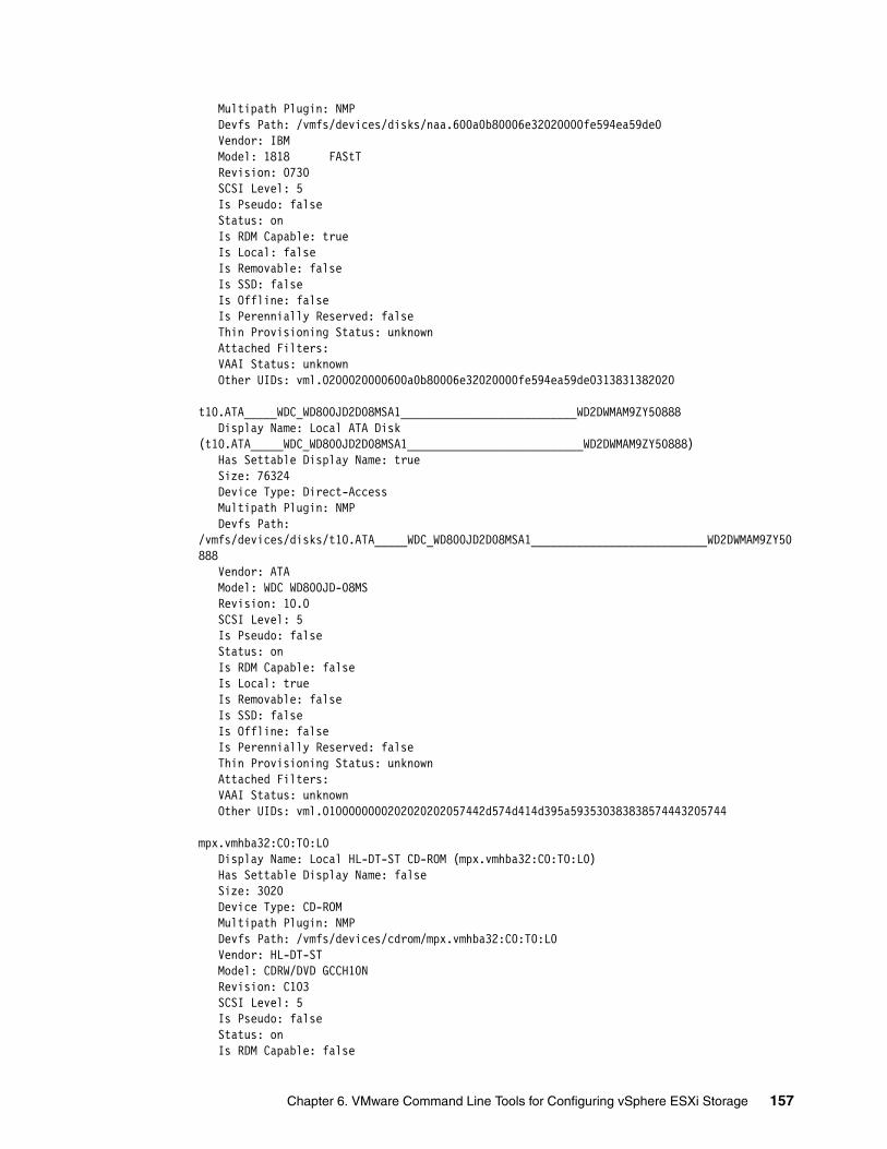
Multipath Plugin: NMP Devfs Path: /vmfs/devices/disks/naa.600a0b80006e32020000fe594ea59de0 Vendor: IBM Model: 1818 FAStT Revision: 0730 SCSI Level: 5 Is Pseudo: false Status: on Is RDM Capable: true Is Local: false Is Removable: false Is SSD: false Is Offline: false Is Perennially Reserved: false Thin Provisioning Status: unknown Attached Filters: VAAI Status: unknown Other UIDs: vml.0200020000600a0b80006e32020000fe594ea59de0313831382020
t10.ATA_____WDC_WD800JD2D08MSA1___________________________WD2DWMAM9ZY50888 Display Name: Local ATA Disk (t10.ATA_____WDC_WD800JD2D08MSA1___________________________WD2DWMAM9ZY50888) Has Settable Display Name: true Size: 76324 Device Type: Direct-Access Multipath Plugin: NMP Devfs Path: /vmfs/devices/disks/t10.ATA_____WDC_WD800JD2D08MSA1___________________________WD2DWMAM9ZY50888 Vendor: ATA Model: WDC WD800JD-08MS Revision: 10.0 SCSI Level: 5 Is Pseudo: false Status: on Is RDM Capable: false Is Local: true Is Removable: false Is SSD: false Is Offline: false Is Perennially Reserved: false Thin Provisioning Status: unknown Attached Filters: VAAI Status: unknown Other UIDs: vml.0100000000202020202057442d574d414d395a593530383838574443205744
mpx.vmhba32:C0:T0:L0 Display Name: Local HL-DT-ST CD-ROM (mpx.vmhba32:C0:T0:L0) Has Settable Display Name: false Size: 3020 Device Type: CD-ROM Multipath Plugin: NMP Devfs Path: /vmfs/devices/cdrom/mpx.vmhba32:C0:T0:L0 Vendor: HL-DT-ST Model: CDRW/DVD GCCH10N Revision: C103 SCSI Level: 5 Is Pseudo: false Status: on Is RDM Capable: false
Chapter 6. VMware Command Line Tools for Configuring vSphere ESXi Storage 157
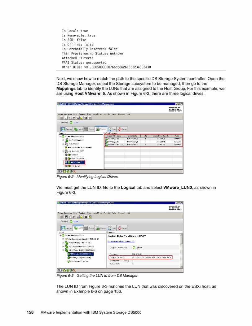
Is Local: true Is Removable: true Is SSD: false Is Offline: false Is Perennially Reserved: false Thin Provisioning Status: unknown Attached Filters: VAAI Status: unsupported Other UIDs: vml.0005000000766d68626133323a303a30
Next, we show how to match the path to the specific DS Storage System controller. Open the DS Storage Manager, select the Storage subsystem to be managed, then go to the Mappings tab to identify the LUNs that are assigned to the Host Group. For this example, we are using Host VMware_5. As shown in Figure 6-2, there are three logical drives.
Figure 6-2 Identifying Logical Drives
We must get the LUN ID. Go to the Logical tab and select VMware_LUN0, as shown in Figure 6-3.
Figure 6-3 Getting the LUN Id from DS Manager
The LUN ID from Figure 6-3 matches the LUN that was discovered on the ESXi host, as shown in Example 6-6 on page 156.
158 VMware Implementation with IBM System Storage DS5000
Appendix A. VMware ESXi Fibre Channel Configuration Checklist
In this appendix, we summarize the best practices and configuration steps that are needed to configure your VMware ESXi Server to work with DS5000 storage subsystems in Fibre Channel (FC) environments. For more information about the settings that are explained in this appendix, see Chapter 3, “Planning the VMware vSphere Storage System Design” on page 29, Chapter 4, “Planning the VMware vSphere Server Design” on page 55, and Chapter 5, “VMware ESXi Server and Storage Configuration” on page 69. Follow the guidelines to maintain the best performance and normal operation of your VMware ESXi environment. You can print out the guidelines to help you with the VMware ESXi Server implementation and configuration, or to assist with troubleshooting.
A
© Copyright IBM Corp. 2012. All rights reserved. 159
Hardware, cabling, and zoning best practices
This section describes hardware, cabling, and zoning best practices to use with VMware ESXi environments.
Hardware Two identical Host Bus Adapters (HBAs) for each VMware ESXi Server:
identical brand
identical firmware
identical settings
QLogic HBA settingsThe following settings should be used in QLogic HBA BIOS:
Adapter Settings Host Adapter BIOS: Disabled (set it to enabled only if booting from SAN).
Fibre Channel Tape Support: Disabled.
Data Rate: Set to fixed rate which is supported by the HBA and the SAN switch.
Advanced Adapter Settings Enable LIP reset: No.
Enable LIP Full Login: Yes.
Enable Target Reset. Yes.
Cabling Each DS5000 controller should have connections to two SAN fabrics.
Each HBA should be cabled into its own SAN fabric.
Disk and Tape traffic on separate HBAs.
SAN Zoning Zone each HBA to see both DS5000 controllers (two paths per HBA - four paths per LUN)
Use 1-to-1 zoning: In each SAN zone, there should only be one HBA and one DS5000 controller port, as shown in the following examples:
– Zone 1: HBA1 with controller A, port 1– Zone 2: HBA1 with controller B, port 1– Zone 3: HBA2 with controller A, port 2– Zone 4: HBA2 with controller B, port 2
Important: Single HBA configurations are allowed, but a single HBA configuration might result in the loss of data access if a path fails.
160 VMware Implementation with IBM System Storage DS5000
DS5000 Settings
This section describes the settings that must be defined in the DS5000 storage subsystem for it to work correctly with VMware ESXi environments.
Host type Host type must be set to VMware. All of the necessary NVSRAM settings are included with
that host type.
LUN settings LUN numbering must be the same for each DS5000 LUN on each VMware ESXi Server.
LUN numbering must start with 0, and raise consecutively with no gaps.
Default LUN id 31 (Access Logical Drive) is not supported and must be removed from the mappings list for each VMware ESXi host and host group.
Segment size Set the segment size to 256 KB
Appendix A. VMware ESXi Fibre Channel Configuration Checklist 161
VMware ESXi Server Settings
This section describes the settings that must be defined in VMware ESXi Server for it to work correctly with DS5000 storage subsystems.
Multipathing policy Path Selection: Most Recently Used
Four paths for each LUN, two showing as Active and two showing as Stand by (each HBA has two paths to each DS5000 controller).
Advanced SettingsTo define these settings, open vSphere client, then click Configuration Advanced Settings (under Software):
Disk.UseDeviceReset=0
Disk.UseLunReset=1
162 VMware Implementation with IBM System Storage DS5000
Restrictions
This section describes the restrictions in VMware ESXi Server and DS5000 storage subsystem environments.
Controller firmware upgradeConcurrent controller firmware that is download is not supported in a storage subsystem environment with the VMware ESXi Server host attached.
SAN and connectivity� VMware ESXi Server hosts supports only the host-agent (out-of-band) managed storage
subsystem configurations. Direct-attached (in-band) management configurations are not supported.
� VMware ESXi Server hosts can support multiple host bus adapters (HBAs) and DS5000 devices. However, there is a restriction on the number of HBAs that can be connected to a single storage subsystem. You can configure up to two HBAs per partition and up to two partitions per storage subsystem. Other HBAs are added for more storage subsystems and other SAN devices, up to the limits of your specific storage subsystem platform.
OtherDynamic Volume Expansion is not supported for VMFS-formatted LUNs.
Important: Do not boot your system from a SATA device.
Appendix A. VMware ESXi Fibre Channel Configuration Checklist 163

164 VMware Implementation with IBM System Storage DS5000
Related publications
We consider the publications that are listed in this section as particularly suitable for a more detailed discussion of the topics in this paper.
IBM Redbooks
For information about ordering the following publications, see “How to get IBM Redbooks publications” on page 165. Some of the publications might be available only in softcopy:
� IBM System Storage DS4000 and Storage Manager V10.30, SG24-7010� IBM Midrange System Storage Hardware Guide, SG24-7676� Implementing an IBM/Cisco SAN, SG24-7545� Implementing an IBM/Brocade SAN with 8 Gbps Directors and Switches, SG24-6116� IBM Midrange System Storage Implementation and Best Practices Guide, SG24-6363� IBM Midrange System Storage Copy Services Guide, SG24-7822
Other resources
The following publication also is relevant as another information source:
Best Practices for Running VMware ESX 3.5 on an IBM DS5000 Storage System http://www-03.ibm.com/support/techdocs/atsmastr.nsf/WebIndex/WP101347
Referenced Web sites
The following web site are is relevant as another information source:
VMware vSphere Online Library at: http://pubs.vmware.com/vsp40
How to get IBM Redbooks publications
You can search for, view, or download IBM Redbooks publications, IBM Redpapers, Technotes, draft publications, and Additional materials, as well as order hardcopy IBM Redbooks publications, at this web site:
http://www.ibm.com/redbooks
© Copyright IBM Corp. 2012. All rights reserved. 165
Help from IBM
IBM Support and downloads
http://www.ibm.com/support
IBM Global Services
http://www.ibm.com/services
166 VMware Implementation with IBM System Storage DS5000

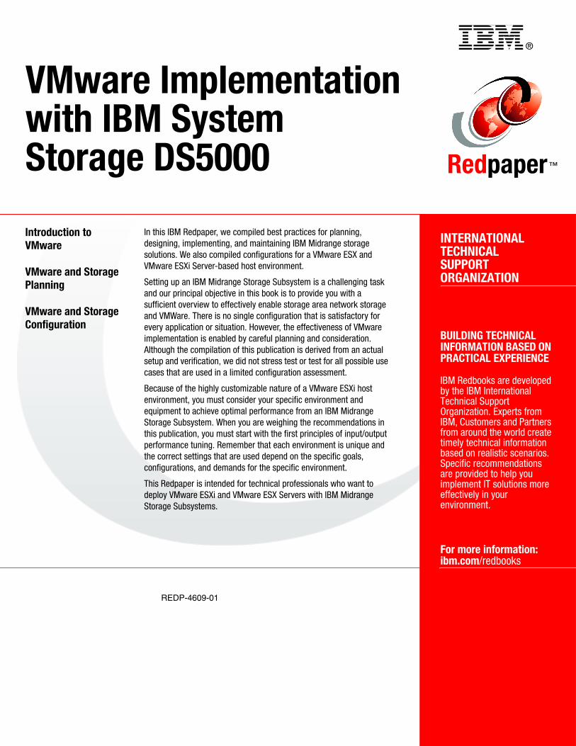
®
REDP-4609-01
INTERNATIONAL TECHNICALSUPPORTORGANIZATION
BUILDING TECHNICAL INFORMATION BASED ON PRACTICAL EXPERIENCE
IBM Redbooks are developed by the IBM International Technical Support Organization. Experts from IBM, Customers and Partners from around the world create timely technical information based on realistic scenarios. Specific recommendations are provided to help you implement IT solutions more effectively in your environment.
For more information:ibm.com/redbooks
Redpaper™
VMware Implementationwith IBM System Storage DS5000
Introduction to VMware
VMware and Storage Planning
VMware and Storage Configuration
In this IBM Redpaper, we compiled best practices for planning, designing, implementing, and maintaining IBM Midrange storage solutions. We also compiled configurations for a VMware ESX and VMware ESXi Server-based host environment.
Setting up an IBM Midrange Storage Subsystem is a challenging task and our principal objective in this book is to provide you with a sufficient overview to effectively enable storage area network storage and VMWare. There is no single configuration that is satisfactory for every application or situation. However, the effectiveness of VMware implementation is enabled by careful planning and consideration. Although the compilation of this publication is derived from an actual setup and verification, we did not stress test or test for all possible use cases that are used in a limited configuration assessment.
Because of the highly customizable nature of a VMware ESXi host environment, you must consider your specific environment and equipment to achieve optimal performance from an IBM Midrange Storage Subsystem. When you are weighing the recommendations in this publication, you must start with the first principles of input/output performance tuning. Remember that each environment is unique and the correct settings that are used depend on the specific goals, configurations, and demands for the specific environment.
This Redpaper is intended for technical professionals who want to deploy VMware ESXi and VMware ESX Servers with IBM Midrange Storage Subsystems.
Back cover


![IBM Storwize V3500img.zhilankeji.com/ibm/storwize_v3500_01.pdf · 2013-12-18 · IBM Storwize V7000 2010 年 10 ... V7000 Storwize V7000 [ Unified ] DS4000, DS5000, Storwize V7000](https://img.pdfslide.net/doc/110x75/5f8da2e2ad21c4137b6552e2/ibm-storwize-2013-12-18-ibm-storwize-v7000-2010-10-v7000-storwize-v7000.jpg)