Embed Size (px)
Citation preview
Cisco Configuration Assurance SolutionVirtual Network Data ServerVNE Server User GuideSoftware Release 3.5
Corporate HeadquartersCisco Systems, Inc.170 West Tasman DriveSan Jose, CA 95134-1706 USAhttp://www.cisco.comTel: 408 526-4000
800 553-NETS (6387)Fax: 408 526-4100
Text Part Number: OL-7553-02

THE SPECIFICATIONS AND INFORMATION REGARDING THE PRODUCTS IN THIS MANUAL ARE SUBJECT TO CHANGE WITHOUT NOTICE. ALL STATEMENTS, INFORMATION, AND RECOMMENDATIONS IN THIS MANUAL ARE BELIEVED TO BE ACCURATE BUT ARE PRESENTED WITHOUT WARRANTY OF ANY KIND, EXPRESS OR IMPLIED. USERS MUST TAKE FULL RESPONSIBILITY FOR THEIR APPLICATION OF ANY PRODUCTS.
THE SOFTWARE LICENSE AND LIMITED WARRANTY FOR THE ACCOMPANYING PRODUCT ARE SET FORTH IN THE INFORMATION PACKET THAT SHIPPED WITH THE PRODUCT AND ARE INCORPORATED HEREIN BY THIS REFERENCE. IF YOU ARE UNABLE TO LOCATE THE SOFTWARE LICENSE OR LIMITED WARRANTY, CONTACT YOUR CISCO REPRESENTATIVE FOR A COPY.
The Cisco implementation of TCP header compression is an adaptation of a program developed by the University of California, Berkeley (UCB) as part of UCB’s public domain version of the UNIX operating system. All rights reserved. Copyright © 1981, Regents of the University of California.
NOTWITHSTANDING ANY OTHER WARRANTY HEREIN, ALL DOCUMENT FILES AND SOFTWARE OF THESE SUPPLIERS ARE PROVIDED “AS IS” WITH ALL FAULTS. CISCO AND THE ABOVE-NAMED SUPPLIERS DISCLAIM ALL WARRANTIES, EXPRESSED OR IMPLIED, INCLUDING, WITHOUT LIMITATION, THOSE OF MERCHANTABILITY, FITNESS FOR A PARTICULAR PURPOSE AND NONINFRINGEMENT OR ARISING FROM A COURSE OF DEALING, USAGE, OR TRADE PRACTICE.
IN NO EVENT SHALL CISCO OR ITS SUPPLIERS BE LIABLE FOR ANY INDIRECT, SPECIAL, CONSEQUENTIAL, OR INCIDENTAL DAMAGES, INCLUDING, WITHOUT LIMITATION, LOST PROFITS OR LOSS OR DAMAGE TO DATA ARISING OUT OF THE USE OR INABILITY TO USE THIS MANUAL, EVEN IF CISCO OR ITS SUPPLIERS HAVE BEEN ADVISED OF THE POSSIBILITY OF SUCH DAMAGES.
Cisco Configuration Assurance SolutionVirtual Network Data ServerVNE Server User GuideCopyright © 2005 Cisco Systems, Inc. All rights reserved.
CCSP, CCVP, the Cisco Square Bridge logo, Follow Me Browsing, and StackWise are trademarks of Cisco Systems, Inc.; Changing the Way We Work, Live, Play, and Learn, and iQuick Study are service marks of Cisco Systems, Inc.; and Access Registrar, Aironet, ASIST, BPX, Catalyst, CCDA, CCDP, CCIE, CCIP, CCNA, CCNP, Cisco, the Cisco Certified Internetwork Expert logo, Cisco IOS, Cisco Press, Cisco Systems, Cisco Systems Capital, the Cisco Systems logo, Cisco Unity, Empowering the Internet Generation, Enterprise/Solver, EtherChannel, EtherFast, EtherSwitch, Fast Step, FormShare, GigaDrive, GigaStack, HomeLink, Internet Quotient, IOS, IP/TV, iQ Expertise, the iQ logo, iQ Net Readiness Scorecard, LightStream, Linksys, MeetingPlace, MGX, the Networkers logo, Networking Academy, Network Registrar, Packet, PIX, Post-Routing, Pre-Routing, ProConnect, RateMUX, ScriptShare, SlideCast, SMARTnet, StrataView Plus, TeleRouter, The Fastest Way to Increase Your Internet Quotient, and TransPath are registered trademarks of Cisco Systems, Inc. and/or its affiliates in the United States and certain other countries.
All other trademarks mentioned in this document or Website are the property of their respective owners. The use of the word partner does not imply a partnership relationship between Cisco and any other company. (0502R)
VNE Server User Guide Copyright
Copyright
Document Copyright
Document Title: VNE Server User Guide Document Part Number: D00228Version: 1
© 1987-2005 OPNET Technologies, Inc.All Rights Reserved. Reproduction, adaptation, or translation without prior written permission is prohibited, except as allowed under the copyright laws.
Software Copyright
Product Name: VNE ServerProduct Release: 3.5
© 1987-2005 OPNET Technologies, Inc.All Rights Reserved.
VNE Server/Release 3.5 VNE-FM-iii
Documentation Conventions VNE Server User Guide
Documentation Conventions
OPNET documentation uses specific formatting and typographic conventions to present the following types of information:
• Objects, examples, and system I/O
• Object hierarchies, notes, and warnings
• Computer commands
• Lists and procedures
Objects, Examples, and System I/O
• Directory paths and file names are in plain Courier typeface:
opnet\release\models\std\ip
• Function names in body text are in italics:
op_dist_outcome()
• The names of functions of interest in example code are in bolded Courier typeface:
/* determine the object ID of packet’s creation module */src_mod_objid = op_pk_creation_mod_get (pkptr);
• Variables are enclosed in angle brackets (< >):
<opnet_user_home>/op_admin/err_log
Object Hierarchies, Notes, and Warnings
Menu hierarchies are indicated by right angle brackets (>); for example:
Open File > Print Setup > Properties...
Attribute hierarchies are represented by angled arrows (➘ ) that indicate that you must drill down to a lower level of the hierarchy:
VNE-FM-iv VNE Server/Release 3.5
VNE Server User Guide Documentation Conventions
Attribute level 1 ➘ Attribute level 2 ➘ Attribute level 3
Note—Notes are indicated by text with the word Note at the beginning of the paragraph. Notes advise you of important supplementary information.
WARNING—Warnings are indicated by text with the word WARNING at the beginning of the paragraph. Warnings advise you of vital information about an operation or system behavior.
Computer Commands
These conventions apply to windowing systems and navigation methods that use the standard graphical-user-interface (GUI) terminology such as click, drag, and dialog box.
• Key combinations appear in the form “press <button>+x”; this means press the <button> and x keys at the same time to do the operation.
• The mouse operations left-click (or click) and right-click indicate that you should press the left mouse button or right mouse button, respectively.
Lists and Procedures
Information is often itemized in bulleted (unordered) or numbered (ordered) lists:
• In bulleted lists, the sequence of items is not important.
• In numbered lists, the sequence of items is important.
Procedures are contained within procedure headings and footings that indicate the start and end of the procedure. Each step of a procedure is numbered to indicate the sequence in which you should do the steps. A step may be followed by a description of the results of that step; such descriptions are preceded by an arrow.
Procedure FM-1 Sample Procedure Format
1 Procedure step.
➥ Result of the procedure step.
2 Procedure step.
End of Procedure FM-1
For more information about using and maintaining OPNET documentation, see the OPNET VNE Server Documentation Guide.
VNE Server/Release 3.5 VNE-FM-v

Documentation Conventions VNE Server User Guide
VNE-FM-vi VNE Server/Release 3.5
VNE Server User Guide —
Document Revision History
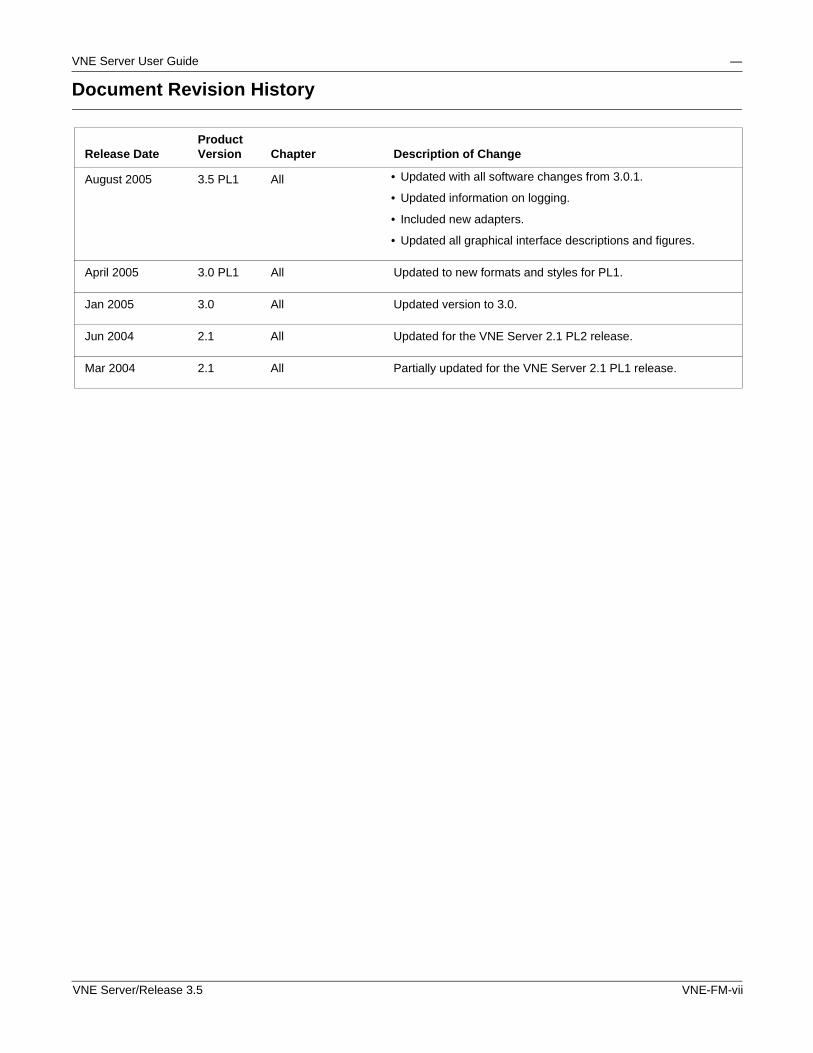
Release DateProduct Version Chapter Description of Change
August 2005 3.5 PL1 All • Updated with all software changes from 3.0.1.
• Updated information on logging.
• Included new adapters.
• Updated all graphical interface descriptions and figures.
April 2005 3.0 PL1 All Updated to new formats and styles for PL1.
Jan 2005 3.0 All Updated version to 3.0.
Jun 2004 2.1 All Updated for the VNE Server 2.1 PL2 release.
Mar 2004 2.1 All Partially updated for the VNE Server 2.1 PL1 release.
VNE Server/Release 3.5 VNE-FM-vii

VNE Server User Guide —
VNE-FM-viii VNE Server/Release 3.5
Contents
Contents
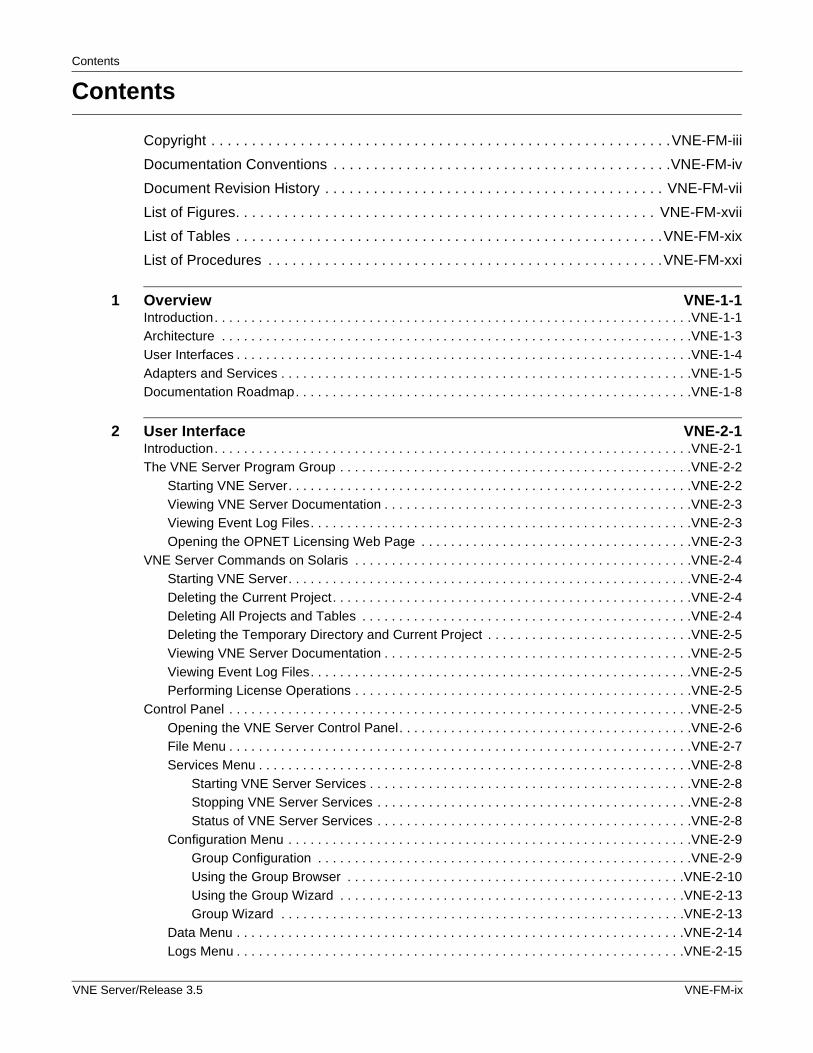
Copyright . . . . . . . . . . . . . . . . . . . . . . . . . . . . . . . . . . . . . . . . . . . . . . . . . . . . . . . . .VNE-FM-iii
Documentation Conventions . . . . . . . . . . . . . . . . . . . . . . . . . . . . . . . . . . . . . . . . . .VNE-FM-iv
Document Revision History . . . . . . . . . . . . . . . . . . . . . . . . . . . . . . . . . . . . . . . . . . VNE-FM-vii
List of Figures. . . . . . . . . . . . . . . . . . . . . . . . . . . . . . . . . . . . . . . . . . . . . . . . . . . . VNE-FM-xvii
List of Tables . . . . . . . . . . . . . . . . . . . . . . . . . . . . . . . . . . . . . . . . . . . . . . . . . . . . .VNE-FM-xix
List of Procedures . . . . . . . . . . . . . . . . . . . . . . . . . . . . . . . . . . . . . . . . . . . . . . . . .VNE-FM-xxi
1 Overview VNE-1-1Introduction. . . . . . . . . . . . . . . . . . . . . . . . . . . . . . . . . . . . . . . . . . . . . . . . . . . . . . . . . . . . . . . . .VNE-1-1Architecture . . . . . . . . . . . . . . . . . . . . . . . . . . . . . . . . . . . . . . . . . . . . . . . . . . . . . . . . . . . . . . . .VNE-1-3User Interfaces . . . . . . . . . . . . . . . . . . . . . . . . . . . . . . . . . . . . . . . . . . . . . . . . . . . . . . . . . . . . . .VNE-1-4Adapters and Services . . . . . . . . . . . . . . . . . . . . . . . . . . . . . . . . . . . . . . . . . . . . . . . . . . . . . . . .VNE-1-5Documentation Roadmap. . . . . . . . . . . . . . . . . . . . . . . . . . . . . . . . . . . . . . . . . . . . . . . . . . . . . .VNE-1-8
2 User Interface VNE-2-1Introduction. . . . . . . . . . . . . . . . . . . . . . . . . . . . . . . . . . . . . . . . . . . . . . . . . . . . . . . . . . . . . . . . .VNE-2-1The VNE Server Program Group . . . . . . . . . . . . . . . . . . . . . . . . . . . . . . . . . . . . . . . . . . . . . . . .VNE-2-2
Starting VNE Server. . . . . . . . . . . . . . . . . . . . . . . . . . . . . . . . . . . . . . . . . . . . . . . . . . . . . . .VNE-2-2Viewing VNE Server Documentation . . . . . . . . . . . . . . . . . . . . . . . . . . . . . . . . . . . . . . . . . .VNE-2-3Viewing Event Log Files. . . . . . . . . . . . . . . . . . . . . . . . . . . . . . . . . . . . . . . . . . . . . . . . . . . .VNE-2-3Opening the OPNET Licensing Web Page . . . . . . . . . . . . . . . . . . . . . . . . . . . . . . . . . . . . .VNE-2-3
VNE Server Commands on Solaris . . . . . . . . . . . . . . . . . . . . . . . . . . . . . . . . . . . . . . . . . . . . . .VNE-2-4Starting VNE Server. . . . . . . . . . . . . . . . . . . . . . . . . . . . . . . . . . . . . . . . . . . . . . . . . . . . . . .VNE-2-4Deleting the Current Project. . . . . . . . . . . . . . . . . . . . . . . . . . . . . . . . . . . . . . . . . . . . . . . . .VNE-2-4Deleting All Projects and Tables . . . . . . . . . . . . . . . . . . . . . . . . . . . . . . . . . . . . . . . . . . . . .VNE-2-4Deleting the Temporary Directory and Current Project . . . . . . . . . . . . . . . . . . . . . . . . . . . .VNE-2-5Viewing VNE Server Documentation . . . . . . . . . . . . . . . . . . . . . . . . . . . . . . . . . . . . . . . . . .VNE-2-5Viewing Event Log Files. . . . . . . . . . . . . . . . . . . . . . . . . . . . . . . . . . . . . . . . . . . . . . . . . . . .VNE-2-5Performing License Operations . . . . . . . . . . . . . . . . . . . . . . . . . . . . . . . . . . . . . . . . . . . . . .VNE-2-5
Control Panel . . . . . . . . . . . . . . . . . . . . . . . . . . . . . . . . . . . . . . . . . . . . . . . . . . . . . . . . . . . . . . .VNE-2-5Opening the VNE Server Control Panel. . . . . . . . . . . . . . . . . . . . . . . . . . . . . . . . . . . . . . . .VNE-2-6File Menu . . . . . . . . . . . . . . . . . . . . . . . . . . . . . . . . . . . . . . . . . . . . . . . . . . . . . . . . . . . . . . .VNE-2-7Services Menu . . . . . . . . . . . . . . . . . . . . . . . . . . . . . . . . . . . . . . . . . . . . . . . . . . . . . . . . . . .VNE-2-8
Starting VNE Server Services . . . . . . . . . . . . . . . . . . . . . . . . . . . . . . . . . . . . . . . . . . . .VNE-2-8Stopping VNE Server Services . . . . . . . . . . . . . . . . . . . . . . . . . . . . . . . . . . . . . . . . . . .VNE-2-8Status of VNE Server Services . . . . . . . . . . . . . . . . . . . . . . . . . . . . . . . . . . . . . . . . . . .VNE-2-8
Configuration Menu . . . . . . . . . . . . . . . . . . . . . . . . . . . . . . . . . . . . . . . . . . . . . . . . . . . . . . .VNE-2-9Group Configuration . . . . . . . . . . . . . . . . . . . . . . . . . . . . . . . . . . . . . . . . . . . . . . . . . . .VNE-2-9Using the Group Browser . . . . . . . . . . . . . . . . . . . . . . . . . . . . . . . . . . . . . . . . . . . . . .VNE-2-10Using the Group Wizard . . . . . . . . . . . . . . . . . . . . . . . . . . . . . . . . . . . . . . . . . . . . . . .VNE-2-13Group Wizard . . . . . . . . . . . . . . . . . . . . . . . . . . . . . . . . . . . . . . . . . . . . . . . . . . . . . . .VNE-2-13
Data Menu . . . . . . . . . . . . . . . . . . . . . . . . . . . . . . . . . . . . . . . . . . . . . . . . . . . . . . . . . . . . .VNE-2-14Logs Menu . . . . . . . . . . . . . . . . . . . . . . . . . . . . . . . . . . . . . . . . . . . . . . . . . . . . . . . . . . . . .VNE-2-15
VNE Server/Release 3.5 VNE-FM-ix
User Guide
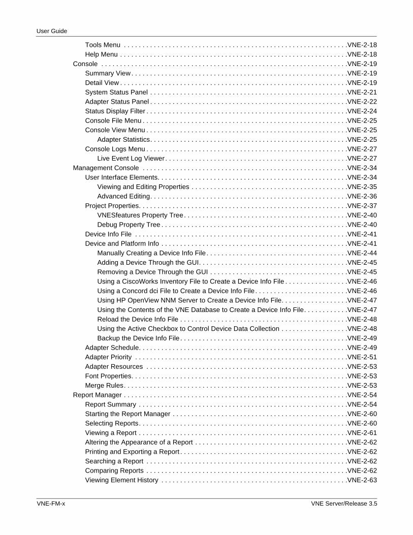
Tools Menu . . . . . . . . . . . . . . . . . . . . . . . . . . . . . . . . . . . . . . . . . . . . . . . . . . . . . . . . . . . .VNE-2-18Help Menu . . . . . . . . . . . . . . . . . . . . . . . . . . . . . . . . . . . . . . . . . . . . . . . . . . . . . . . . . . . . .VNE-2-18
Console . . . . . . . . . . . . . . . . . . . . . . . . . . . . . . . . . . . . . . . . . . . . . . . . . . . . . . . . . . . . . . . . . .VNE-2-19Summary View . . . . . . . . . . . . . . . . . . . . . . . . . . . . . . . . . . . . . . . . . . . . . . . . . . . . . . . . . .VNE-2-19Detail View . . . . . . . . . . . . . . . . . . . . . . . . . . . . . . . . . . . . . . . . . . . . . . . . . . . . . . . . . . . . .VNE-2-19System Status Panel . . . . . . . . . . . . . . . . . . . . . . . . . . . . . . . . . . . . . . . . . . . . . . . . . . . . .VNE-2-21Adapter Status Panel . . . . . . . . . . . . . . . . . . . . . . . . . . . . . . . . . . . . . . . . . . . . . . . . . . . . .VNE-2-22Status Display Filter . . . . . . . . . . . . . . . . . . . . . . . . . . . . . . . . . . . . . . . . . . . . . . . . . . . . . .VNE-2-24Console File Menu . . . . . . . . . . . . . . . . . . . . . . . . . . . . . . . . . . . . . . . . . . . . . . . . . . . . . . .VNE-2-25Console View Menu . . . . . . . . . . . . . . . . . . . . . . . . . . . . . . . . . . . . . . . . . . . . . . . . . . . . . .VNE-2-25
Adapter Statistics. . . . . . . . . . . . . . . . . . . . . . . . . . . . . . . . . . . . . . . . . . . . . . . . . . . . .VNE-2-25Console Logs Menu . . . . . . . . . . . . . . . . . . . . . . . . . . . . . . . . . . . . . . . . . . . . . . . . . . . . . .VNE-2-27
Live Event Log Viewer . . . . . . . . . . . . . . . . . . . . . . . . . . . . . . . . . . . . . . . . . . . . . . . . .VNE-2-27Management Console . . . . . . . . . . . . . . . . . . . . . . . . . . . . . . . . . . . . . . . . . . . . . . . . . . . . . . .VNE-2-34
User Interface Elements. . . . . . . . . . . . . . . . . . . . . . . . . . . . . . . . . . . . . . . . . . . . . . . . . . .VNE-2-34Viewing and Editing Properties . . . . . . . . . . . . . . . . . . . . . . . . . . . . . . . . . . . . . . . . . .VNE-2-35Advanced Editing. . . . . . . . . . . . . . . . . . . . . . . . . . . . . . . . . . . . . . . . . . . . . . . . . . . . .VNE-2-36
Project Properties. . . . . . . . . . . . . . . . . . . . . . . . . . . . . . . . . . . . . . . . . . . . . . . . . . . . . . . .VNE-2-37VNESfeatures Property Tree. . . . . . . . . . . . . . . . . . . . . . . . . . . . . . . . . . . . . . . . . . . .VNE-2-40Debug Property Tree . . . . . . . . . . . . . . . . . . . . . . . . . . . . . . . . . . . . . . . . . . . . . . . . . .VNE-2-40
Device Info File . . . . . . . . . . . . . . . . . . . . . . . . . . . . . . . . . . . . . . . . . . . . . . . . . . . . . . . . .VNE-2-41Device and Platform Info . . . . . . . . . . . . . . . . . . . . . . . . . . . . . . . . . . . . . . . . . . . . . . . . . .VNE-2-41
Manually Creating a Device Info File . . . . . . . . . . . . . . . . . . . . . . . . . . . . . . . . . . . . . .VNE-2-44Adding a Device Through the GUI. . . . . . . . . . . . . . . . . . . . . . . . . . . . . . . . . . . . . . . .VNE-2-45Removing a Device Through the GUI . . . . . . . . . . . . . . . . . . . . . . . . . . . . . . . . . . . . .VNE-2-45Using a CiscoWorks Inventory File to Create a Device Info File . . . . . . . . . . . . . . . . .VNE-2-46Using a Concord dci File to Create a Device Info File . . . . . . . . . . . . . . . . . . . . . . . . .VNE-2-46Using HP OpenView NNM Server to Create a Device Info File. . . . . . . . . . . . . . . . . .VNE-2-47Using the Contents of the VNE Database to Create a Device Info File. . . . . . . . . . . .VNE-2-47Reload the Device Info File . . . . . . . . . . . . . . . . . . . . . . . . . . . . . . . . . . . . . . . . . . . . .VNE-2-48Using the Active Checkbox to Control Device Data Collection . . . . . . . . . . . . . . . . . .VNE-2-48Backup the Device Info File . . . . . . . . . . . . . . . . . . . . . . . . . . . . . . . . . . . . . . . . . . . . .VNE-2-49
Adapter Schedule. . . . . . . . . . . . . . . . . . . . . . . . . . . . . . . . . . . . . . . . . . . . . . . . . . . . . . . .VNE-2-49Adapter Priority . . . . . . . . . . . . . . . . . . . . . . . . . . . . . . . . . . . . . . . . . . . . . . . . . . . . . . . . .VNE-2-51Adapter Resources . . . . . . . . . . . . . . . . . . . . . . . . . . . . . . . . . . . . . . . . . . . . . . . . . . . . . .VNE-2-53Font Properties. . . . . . . . . . . . . . . . . . . . . . . . . . . . . . . . . . . . . . . . . . . . . . . . . . . . . . . . . .VNE-2-53Merge Rules. . . . . . . . . . . . . . . . . . . . . . . . . . . . . . . . . . . . . . . . . . . . . . . . . . . . . . . . . . . .VNE-2-53
Report Manager . . . . . . . . . . . . . . . . . . . . . . . . . . . . . . . . . . . . . . . . . . . . . . . . . . . . . . . . . . . .VNE-2-54Report Summary . . . . . . . . . . . . . . . . . . . . . . . . . . . . . . . . . . . . . . . . . . . . . . . . . . . . . . . .VNE-2-54Starting the Report Manager . . . . . . . . . . . . . . . . . . . . . . . . . . . . . . . . . . . . . . . . . . . . . . .VNE-2-60Selecting Reports. . . . . . . . . . . . . . . . . . . . . . . . . . . . . . . . . . . . . . . . . . . . . . . . . . . . . . . .VNE-2-60Viewing a Report . . . . . . . . . . . . . . . . . . . . . . . . . . . . . . . . . . . . . . . . . . . . . . . . . . . . . . . .VNE-2-61Altering the Appearance of a Report . . . . . . . . . . . . . . . . . . . . . . . . . . . . . . . . . . . . . . . . .VNE-2-62Printing and Exporting a Report . . . . . . . . . . . . . . . . . . . . . . . . . . . . . . . . . . . . . . . . . . . . .VNE-2-62Searching a Report . . . . . . . . . . . . . . . . . . . . . . . . . . . . . . . . . . . . . . . . . . . . . . . . . . . . . .VNE-2-62Comparing Reports . . . . . . . . . . . . . . . . . . . . . . . . . . . . . . . . . . . . . . . . . . . . . . . . . . . . . .VNE-2-62Viewing Element History . . . . . . . . . . . . . . . . . . . . . . . . . . . . . . . . . . . . . . . . . . . . . . . . . .VNE-2-63
VNE-FM-x VNE Server/Release 3.5
Contents
Report Manager File Menu . . . . . . . . . . . . . . . . . . . . . . . . . . . . . . . . . . . . . . . . . . . . . . . .VNE-2-65Report Manager Options Menu . . . . . . . . . . . . . . . . . . . . . . . . . . . . . . . . . . . . . . . . . . . . .VNE-2-66
Network Browser . . . . . . . . . . . . . . . . . . . . . . . . . . . . . . . . . . . . . . . . . . . . . . . . . . . . . . . . . . .VNE-2-67Starting the Network Browser . . . . . . . . . . . . . . . . . . . . . . . . . . . . . . . . . . . . . . . . . . .VNE-2-67Deleting Network Elements and Blocking Import. . . . . . . . . . . . . . . . . . . . . . . . . . . . .VNE-2-70Network Browser Menus . . . . . . . . . . . . . . . . . . . . . . . . . . . . . . . . . . . . . . . . . . . . . . .VNE-2-72
Preferences . . . . . . . . . . . . . . . . . . . . . . . . . . . . . . . . . . . . . . . . . . . . . . . . . . . . . . . . . . . . . . .VNE-2-73vne_import.create_serial_cloud. . . . . . . . . . . . . . . . . . . . . . . . . . . . . . . . . . . . . . . . . .VNE-2-73vne_import.dbox_start_function . . . . . . . . . . . . . . . . . . . . . . . . . . . . . . . . . . . . . . . . .VNE-2-73vne_import.ior_file . . . . . . . . . . . . . . . . . . . . . . . . . . . . . . . . . . . . . . . . . . . . . . . . . . . .VNE-2-73vne_import.post_operation_function . . . . . . . . . . . . . . . . . . . . . . . . . . . . . . . . . . . . . .VNE-2-73vne_import.post_operation_library . . . . . . . . . . . . . . . . . . . . . . . . . . . . . . . . . . . . . . .VNE-2-73vne_import.postproc_function . . . . . . . . . . . . . . . . . . . . . . . . . . . . . . . . . . . . . . . . . . .VNE-2-74vne_import.process_library . . . . . . . . . . . . . . . . . . . . . . . . . . . . . . . . . . . . . . . . . . . . .VNE-2-74vne_import.ssm_directory . . . . . . . . . . . . . . . . . . . . . . . . . . . . . . . . . . . . . . . . . . . . . .VNE-2-74vne_import.state_destroy_function . . . . . . . . . . . . . . . . . . . . . . . . . . . . . . . . . . . . . . .VNE-2-74vne_import.state_library . . . . . . . . . . . . . . . . . . . . . . . . . . . . . . . . . . . . . . . . . . . . . . .VNE-2-74vne_import.state_register_function . . . . . . . . . . . . . . . . . . . . . . . . . . . . . . . . . . . . . . .VNE-2-75
3 Adapters and Services VNE-3-1Introduction. . . . . . . . . . . . . . . . . . . . . . . . . . . . . . . . . . . . . . . . . . . . . . . . . . . . . . . . . . . . . . . . .VNE-3-1Device Config File Collection . . . . . . . . . . . . . . . . . . . . . . . . . . . . . . . . . . . . . . . . . . . . . . . . . . .VNE-3-1
Configuring Adapter Resources . . . . . . . . . . . . . . . . . . . . . . . . . . . . . . . . . . . . . . . . . .VNE-3-2Configuration Considerations for Device Config File Collection . . . . . . . . . . . . . . . . . .VNE-3-7
Configuring Device Login Properties . . . . . . . . . . . . . . . . . . . . . . . . . . . . . . . . . . . . . . . . . .VNE-3-8Configuring Show Command Properties . . . . . . . . . . . . . . . . . . . . . . . . . . . . . . . . . . . . . . .VNE-3-9Changing Adapter Login and Show Command Properties . . . . . . . . . . . . . . . . . . . . . . . .VNE-3-11Check Point FireWall-1 Support. . . . . . . . . . . . . . . . . . . . . . . . . . . . . . . . . . . . . . . . . . . . .VNE-3-13
Nokia IPSO Configuration Command Support . . . . . . . . . . . . . . . . . . . . . . . . . . . . . .VNE-3-14Support for Juniper ERX . . . . . . . . . . . . . . . . . . . . . . . . . . . . . . . . . . . . . . . . . . . . . . . . . .VNE-3-15
Device Configuration Import Adapters . . . . . . . . . . . . . . . . . . . . . . . . . . . . . . . . . . . . . . . . . . .VNE-3-15Device Config File Import. . . . . . . . . . . . . . . . . . . . . . . . . . . . . . . . . . . . . . . . . . . . . . . . . .VNE-3-16
Expanded Command Support . . . . . . . . . . . . . . . . . . . . . . . . . . . . . . . . . . . . . . . . . . .VNE-3-17Configuring Adapter Resources . . . . . . . . . . . . . . . . . . . . . . . . . . . . . . . . . . . . . . . . .VNE-3-18
Device ifIndex Import . . . . . . . . . . . . . . . . . . . . . . . . . . . . . . . . . . . . . . . . . . . . . . . . . . . . .VNE-3-19Device FR Map Import . . . . . . . . . . . . . . . . . . . . . . . . . . . . . . . . . . . . . . . . . . . . . . . . . . . .VNE-3-19Device Version Import . . . . . . . . . . . . . . . . . . . . . . . . . . . . . . . . . . . . . . . . . . . . . . . . . . . .VNE-3-20Device IP Route Import . . . . . . . . . . . . . . . . . . . . . . . . . . . . . . . . . . . . . . . . . . . . . . . . . . .VNE-3-20Device CDP Import . . . . . . . . . . . . . . . . . . . . . . . . . . . . . . . . . . . . . . . . . . . . . . . . . . . . . .VNE-3-20Device ARP Table Import. . . . . . . . . . . . . . . . . . . . . . . . . . . . . . . . . . . . . . . . . . . . . . . . . .VNE-3-20Device Interface Import . . . . . . . . . . . . . . . . . . . . . . . . . . . . . . . . . . . . . . . . . . . . . . . . . . .VNE-3-20Device Module Import . . . . . . . . . . . . . . . . . . . . . . . . . . . . . . . . . . . . . . . . . . . . . . . . . . . .VNE-3-21Device VTP Status Import . . . . . . . . . . . . . . . . . . . . . . . . . . . . . . . . . . . . . . . . . . . . . . . . .VNE-3-21Device CAM Table Import . . . . . . . . . . . . . . . . . . . . . . . . . . . . . . . . . . . . . . . . . . . . . . . . .VNE-3-21Device VLAN Database Import . . . . . . . . . . . . . . . . . . . . . . . . . . . . . . . . . . . . . . . . . . . . .VNE-3-21Device Trunk Import. . . . . . . . . . . . . . . . . . . . . . . . . . . . . . . . . . . . . . . . . . . . . . . . . . . . . .VNE-3-21Nortel EPIC Output Import . . . . . . . . . . . . . . . . . . . . . . . . . . . . . . . . . . . . . . . . . . . . . . . . .VNE-3-21
VNE Server/Release 3.5 VNE-FM-xi
User Guide
Remote File Collection . . . . . . . . . . . . . . . . . . . . . . . . . . . . . . . . . . . . . . . . . . . . . . . . . . . . . . .VNE-3-21CiscoWorks Config File Collection . . . . . . . . . . . . . . . . . . . . . . . . . . . . . . . . . . . . . . . . . . . . . .VNE-3-24CiscoWorks Adapters . . . . . . . . . . . . . . . . . . . . . . . . . . . . . . . . . . . . . . . . . . . . . . . . . . . . . . . .VNE-3-26
CiscoWorks Config File Import. . . . . . . . . . . . . . . . . . . . . . . . . . . . . . . . . . . . . . . . . . . . . .VNE-3-26CiscoWorks RME Database Import . . . . . . . . . . . . . . . . . . . . . . . . . . . . . . . . . . . . . . . . . .VNE-3-27CiscoWorks ANI Database Import . . . . . . . . . . . . . . . . . . . . . . . . . . . . . . . . . . . . . . . . . . .VNE-3-28Cisco WAN Manager Import . . . . . . . . . . . . . . . . . . . . . . . . . . . . . . . . . . . . . . . . . . . . . . .VNE-3-29
Importing from CET Files. . . . . . . . . . . . . . . . . . . . . . . . . . . . . . . . . . . . . . . . . . . . . . .VNE-3-30Importing by Connecting to CWM Database . . . . . . . . . . . . . . . . . . . . . . . . . . . . . . . .VNE-3-32
Device MIB Configuration Import . . . . . . . . . . . . . . . . . . . . . . . . . . . . . . . . . . . . . . . . . . . . . . .VNE-3-33Creating CDP Neighbors . . . . . . . . . . . . . . . . . . . . . . . . . . . . . . . . . . . . . . . . . . . . . . .VNE-3-34
Support for SNMPv3 . . . . . . . . . . . . . . . . . . . . . . . . . . . . . . . . . . . . . . . . . . . . . . . . . . . . .VNE-3-35HP OpenView NNM Import. . . . . . . . . . . . . . . . . . . . . . . . . . . . . . . . . . . . . . . . . . . . . . . . . . . .VNE-3-36DNS Alias Import . . . . . . . . . . . . . . . . . . . . . . . . . . . . . . . . . . . . . . . . . . . . . . . . . . . . . . . . . . .VNE-3-37Link and Connection Inference Service . . . . . . . . . . . . . . . . . . . . . . . . . . . . . . . . . . . . . . . . . .VNE-3-37
Layer-2 Inference . . . . . . . . . . . . . . . . . . . . . . . . . . . . . . . . . . . . . . . . . . . . . . . . . . . . . . . .VNE-3-38Inference of Aggregate Links . . . . . . . . . . . . . . . . . . . . . . . . . . . . . . . . . . . . . . . . . . . . . . .VNE-3-38Advanced Options . . . . . . . . . . . . . . . . . . . . . . . . . . . . . . . . . . . . . . . . . . . . . . . . . . . . . . .VNE-3-39
Trace Route Link Inference Service . . . . . . . . . . . . . . . . . . . . . . . . . . . . . . . . . . . . . . . . . . . . .VNE-3-41MIB-Based Interface Utilization Import . . . . . . . . . . . . . . . . . . . . . . . . . . . . . . . . . . . . . . . . . . .VNE-3-43Concord eHealth Network Utilization Import. . . . . . . . . . . . . . . . . . . . . . . . . . . . . . . . . . . . . . .VNE-3-44StatScout Interface Utilization Import . . . . . . . . . . . . . . . . . . . . . . . . . . . . . . . . . . . . . . . . . . . .VNE-3-47MRTG Interface Utilization Import . . . . . . . . . . . . . . . . . . . . . . . . . . . . . . . . . . . . . . . . . . . . . .VNE-3-47InfoVista Network Utilization Import . . . . . . . . . . . . . . . . . . . . . . . . . . . . . . . . . . . . . . . . . . . . .VNE-3-51Demand Import and Processing . . . . . . . . . . . . . . . . . . . . . . . . . . . . . . . . . . . . . . . . . . . . . . . .VNE-3-53
Traffic Mapping Using Node Traffic Alias . . . . . . . . . . . . . . . . . . . . . . . . . . . . . . . . . .VNE-3-53Improved Reporting on Demands . . . . . . . . . . . . . . . . . . . . . . . . . . . . . . . . . . . . . . . .VNE-3-56
Cisco Netflow Import . . . . . . . . . . . . . . . . . . . . . . . . . . . . . . . . . . . . . . . . . . . . . . . . . . . . . . . .VNE-3-57NetScout nGenius Import . . . . . . . . . . . . . . . . . . . . . . . . . . . . . . . . . . . . . . . . . . . . . . . . . . . . .VNE-3-58Cflowd Import . . . . . . . . . . . . . . . . . . . . . . . . . . . . . . . . . . . . . . . . . . . . . . . . . . . . . . . . . . . . . .VNE-3-59Demand Traffic Processing Service . . . . . . . . . . . . . . . . . . . . . . . . . . . . . . . . . . . . . . . . . . . . .VNE-3-59Post Processor Service . . . . . . . . . . . . . . . . . . . . . . . . . . . . . . . . . . . . . . . . . . . . . . . . . . . . . .VNE-3-59ASCII Generic Data Import . . . . . . . . . . . . . . . . . . . . . . . . . . . . . . . . . . . . . . . . . . . . . . . . . . . .VNE-3-59Database Aging Service . . . . . . . . . . . . . . . . . . . . . . . . . . . . . . . . . . . . . . . . . . . . . . . . . . . . . .VNE-3-62Maintenance Service . . . . . . . . . . . . . . . . . . . . . . . . . . . . . . . . . . . . . . . . . . . . . . . . . . . . . . . .VNE-3-62Change Records Maintenance Service . . . . . . . . . . . . . . . . . . . . . . . . . . . . . . . . . . . . . . . . . .VNE-3-64Report Export Service . . . . . . . . . . . . . . . . . . . . . . . . . . . . . . . . . . . . . . . . . . . . . . . . . . . . . . .VNE-3-64
Adapter Configuration . . . . . . . . . . . . . . . . . . . . . . . . . . . . . . . . . . . . . . . . . . . . . . . . . . . .VNE-3-65Improved Navigation of Web Reports . . . . . . . . . . . . . . . . . . . . . . . . . . . . . . . . . . . . . . . .VNE-3-67Common Reports . . . . . . . . . . . . . . . . . . . . . . . . . . . . . . . . . . . . . . . . . . . . . . . . . . . . . . . .VNE-3-68Export of Detailed Reports . . . . . . . . . . . . . . . . . . . . . . . . . . . . . . . . . . . . . . . . . . . . . . . . .VNE-3-70Publishing to OPNET Report Server . . . . . . . . . . . . . . . . . . . . . . . . . . . . . . . . . . . . . . . . .VNE-3-70
Interface Utilization Rollup Service. . . . . . . . . . . . . . . . . . . . . . . . . . . . . . . . . . . . . . . . . . . . . .VNE-3-71HP OpenView Performance Agent Import . . . . . . . . . . . . . . . . . . . . . . . . . . . . . . . . . . . . .VNE-3-72SMARTS Import . . . . . . . . . . . . . . . . . . . . . . . . . . . . . . . . . . . . . . . . . . . . . . . . . . . . . . . . .VNE-3-72
External Adapter. . . . . . . . . . . . . . . . . . . . . . . . . . . . . . . . . . . . . . . . . . . . . . . . . . . . . . . . . . . .VNE-3-73
VNE-FM-xii VNE Server/Release 3.5
Contents
Demand Traffic Rollup Service. . . . . . . . . . . . . . . . . . . . . . . . . . . . . . . . . . . . . . . . . . . . . . . . .VNE-3-76Export Service . . . . . . . . . . . . . . . . . . . . . . . . . . . . . . . . . . . . . . . . . . . . . . . . . . . . . . . . . . . . .VNE-3-77Testing Adapters . . . . . . . . . . . . . . . . . . . . . . . . . . . . . . . . . . . . . . . . . . . . . . . . . . . . . . . . . . .VNE-3-78
4 Operation VNE-4-1Introduction. . . . . . . . . . . . . . . . . . . . . . . . . . . . . . . . . . . . . . . . . . . . . . . . . . . . . . . . . . . . . . . . .VNE-4-1VNE Server Workflow. . . . . . . . . . . . . . . . . . . . . . . . . . . . . . . . . . . . . . . . . . . . . . . . . . . . . . . . .VNE-4-2
Installation . . . . . . . . . . . . . . . . . . . . . . . . . . . . . . . . . . . . . . . . . . . . . . . . . . . . . . . . . . . . . .VNE-4-2Configuration . . . . . . . . . . . . . . . . . . . . . . . . . . . . . . . . . . . . . . . . . . . . . . . . . . . . . . . . . . . .VNE-4-3Continuous Operation . . . . . . . . . . . . . . . . . . . . . . . . . . . . . . . . . . . . . . . . . . . . . . . . . . . . .VNE-4-3
Starting VNE Server . . . . . . . . . . . . . . . . . . . . . . . . . . . . . . . . . . . . . . . . . . . . . . . . . . . . . . . . . .VNE-4-4Rebooting the VNE Server Host . . . . . . . . . . . . . . . . . . . . . . . . . . . . . . . . . . . . . . . . . . . . .VNE-4-4
Configuring VNE Server . . . . . . . . . . . . . . . . . . . . . . . . . . . . . . . . . . . . . . . . . . . . . . . . . . . . . . .VNE-4-5Creating Device Access Information . . . . . . . . . . . . . . . . . . . . . . . . . . . . . . . . . . . . . . . . . .VNE-4-5
Create a Device Info File Offline . . . . . . . . . . . . . . . . . . . . . . . . . . . . . . . . . . . . . . . . . .VNE-4-5Create a Device Info File Online . . . . . . . . . . . . . . . . . . . . . . . . . . . . . . . . . . . . . . . . . .VNE-4-6
Choosing Adapters. . . . . . . . . . . . . . . . . . . . . . . . . . . . . . . . . . . . . . . . . . . . . . . . . . . . . . . .VNE-4-7CiscoWorks Adapters . . . . . . . . . . . . . . . . . . . . . . . . . . . . . . . . . . . . . . . . . . . . . . . . . .VNE-4-7Collecting Utilization Data . . . . . . . . . . . . . . . . . . . . . . . . . . . . . . . . . . . . . . . . . . . . . . .VNE-4-8
Configuring and Testing Adapters . . . . . . . . . . . . . . . . . . . . . . . . . . . . . . . . . . . . . . . . . . . .VNE-4-9Evaluating the Network Model . . . . . . . . . . . . . . . . . . . . . . . . . . . . . . . . . . . . . . . . . . . . . . .VNE-4-9Scheduling Adapters . . . . . . . . . . . . . . . . . . . . . . . . . . . . . . . . . . . . . . . . . . . . . . . . . . . . .VNE-4-10
MIB-Based Interface Utilization Import Adapter. . . . . . . . . . . . . . . . . . . . . . . . . . . . . .VNE-4-11Chaining Adapters . . . . . . . . . . . . . . . . . . . . . . . . . . . . . . . . . . . . . . . . . . . . . . . . . . . .VNE-4-11
Continuous Operation. . . . . . . . . . . . . . . . . . . . . . . . . . . . . . . . . . . . . . . . . . . . . . . . . . . . . . . .VNE-4-14Using the VNE Server Control Panel to Start and Monitor Data Collection . . . . . . . . . . . .VNE-4-14
Starting Data Collection for the First Time. . . . . . . . . . . . . . . . . . . . . . . . . . . . . . . . . .VNE-4-14Monitoring Data Collection . . . . . . . . . . . . . . . . . . . . . . . . . . . . . . . . . . . . . . . . . . . . .VNE-4-15
Using the Report Manager . . . . . . . . . . . . . . . . . . . . . . . . . . . . . . . . . . . . . . . . . . . . . . . . .VNE-4-16Using the Network Browser . . . . . . . . . . . . . . . . . . . . . . . . . . . . . . . . . . . . . . . . . . . . . . . .VNE-4-20
5 Administration VNE-5-1Introduction. . . . . . . . . . . . . . . . . . . . . . . . . . . . . . . . . . . . . . . . . . . . . . . . . . . . . . . . . . . . . . . . .VNE-5-1VNE Server Administration. . . . . . . . . . . . . . . . . . . . . . . . . . . . . . . . . . . . . . . . . . . . . . . . . . . . .VNE-5-1
Windows Services . . . . . . . . . . . . . . . . . . . . . . . . . . . . . . . . . . . . . . . . . . . . . . . . . . . . . . . .VNE-5-1Important Files . . . . . . . . . . . . . . . . . . . . . . . . . . . . . . . . . . . . . . . . . . . . . . . . . . . . . . . . . . .VNE-5-2Temporary Directory . . . . . . . . . . . . . . . . . . . . . . . . . . . . . . . . . . . . . . . . . . . . . . . . . . . . . .VNE-5-3Managing Projects . . . . . . . . . . . . . . . . . . . . . . . . . . . . . . . . . . . . . . . . . . . . . . . . . . . . . . . .VNE-5-5
Choosing a Project Name . . . . . . . . . . . . . . . . . . . . . . . . . . . . . . . . . . . . . . . . . . . . . . .VNE-5-5Reconfiguring VNE Server Data Collection . . . . . . . . . . . . . . . . . . . . . . . . . . . . . . . . . .VNE-5-6
Managing Logs and Traffic Data . . . . . . . . . . . . . . . . . . . . . . . . . . . . . . . . . . . . . . . . . . . . .VNE-5-7Managing Log File Growth . . . . . . . . . . . . . . . . . . . . . . . . . . . . . . . . . . . . . . . . . . . . . .VNE-5-7Managing Traffic Data Growth. . . . . . . . . . . . . . . . . . . . . . . . . . . . . . . . . . . . . . . . . . . .VNE-5-8
Exporting Reports to Files . . . . . . . . . . . . . . . . . . . . . . . . . . . . . . . . . . . . . . . . . . . . . . . . . .VNE-5-9Software Upgrades . . . . . . . . . . . . . . . . . . . . . . . . . . . . . . . . . . . . . . . . . . . . . . . . . . . . . .VNE-5-10Oracle Performance Enhancement . . . . . . . . . . . . . . . . . . . . . . . . . . . . . . . . . . . . . . . . . .VNE-5-11Product Licensing. . . . . . . . . . . . . . . . . . . . . . . . . . . . . . . . . . . . . . . . . . . . . . . . . . . . . . . .VNE-5-12
VNE Server/Release 3.5 VNE-FM-xiii
User Guide
Deployment Scenarios . . . . . . . . . . . . . . . . . . . . . . . . . . . . . . . . . . . . . . . . . . . . . . . .VNE-5-12License Administration . . . . . . . . . . . . . . . . . . . . . . . . . . . . . . . . . . . . . . . . . . . . . . . .VNE-5-13Restrictions and Limitations. . . . . . . . . . . . . . . . . . . . . . . . . . . . . . . . . . . . . . . . . . . . .VNE-5-15Licensing Resources . . . . . . . . . . . . . . . . . . . . . . . . . . . . . . . . . . . . . . . . . . . . . . . . . .VNE-5-15Command Line Utilities . . . . . . . . . . . . . . . . . . . . . . . . . . . . . . . . . . . . . . . . . . . . . . . .VNE-5-16Licensing Operations. . . . . . . . . . . . . . . . . . . . . . . . . . . . . . . . . . . . . . . . . . . . . . . . . .VNE-5-17
Oracle Administration . . . . . . . . . . . . . . . . . . . . . . . . . . . . . . . . . . . . . . . . . . . . . . . . . . . . . . . .VNE-5-22Important Files . . . . . . . . . . . . . . . . . . . . . . . . . . . . . . . . . . . . . . . . . . . . . . . . . . . . . . . . . .VNE-5-22Oracle Net Services . . . . . . . . . . . . . . . . . . . . . . . . . . . . . . . . . . . . . . . . . . . . . . . . . . . . . .VNE-5-23Account Management . . . . . . . . . . . . . . . . . . . . . . . . . . . . . . . . . . . . . . . . . . . . . . . . . . . .VNE-5-25
Setting Up VNE Server Database Accounts within Oracle . . . . . . . . . . . . . . . . . . . . .VNE-5-25Verifying the Oracle Configuration. . . . . . . . . . . . . . . . . . . . . . . . . . . . . . . . . . . . . . . .VNE-5-26Removing VNE Server Database Accounts within Oracle. . . . . . . . . . . . . . . . . . . . . .VNE-5-26
Monitoring the Database . . . . . . . . . . . . . . . . . . . . . . . . . . . . . . . . . . . . . . . . . . . . . . . . . .VNE-5-27Backup and Recovery . . . . . . . . . . . . . . . . . . . . . . . . . . . . . . . . . . . . . . . . . . . . . . . . . . . .VNE-5-35
Network Management System Administration . . . . . . . . . . . . . . . . . . . . . . . . . . . . . . . . . . . . .VNE-5-37Configuring HP OpenView . . . . . . . . . . . . . . . . . . . . . . . . . . . . . . . . . . . . . . . . . . . . . . . . .VNE-5-37Configuring CiscoWorks. . . . . . . . . . . . . . . . . . . . . . . . . . . . . . . . . . . . . . . . . . . . . . . . . . .VNE-5-38
CiscoWorks on a Windows Host . . . . . . . . . . . . . . . . . . . . . . . . . . . . . . . . . . . . . . . . .VNE-5-38CiscoWorks on a UNIX Host . . . . . . . . . . . . . . . . . . . . . . . . . . . . . . . . . . . . . . . . . . . .VNE-5-39Collecting CiscoWorks Server Information . . . . . . . . . . . . . . . . . . . . . . . . . . . . . . . . .VNE-5-39Collecting a CiscoWorks Inventory File . . . . . . . . . . . . . . . . . . . . . . . . . . . . . . . . . . . .VNE-5-40
Configuring Concord eHealth. . . . . . . . . . . . . . . . . . . . . . . . . . . . . . . . . . . . . . . . . . . . . . .VNE-5-41Configuring MRTG . . . . . . . . . . . . . . . . . . . . . . . . . . . . . . . . . . . . . . . . . . . . . . . . . . . . . . .VNE-5-41Configuring InfoVista . . . . . . . . . . . . . . . . . . . . . . . . . . . . . . . . . . . . . . . . . . . . . . . . . . . . .VNE-5-42
App A Troubleshooting VNE-A-1Introduction. . . . . . . . . . . . . . . . . . . . . . . . . . . . . . . . . . . . . . . . . . . . . . . . . . . . . . . . . . . . . . . . VNE-A-1Tips for Using VNE Server . . . . . . . . . . . . . . . . . . . . . . . . . . . . . . . . . . . . . . . . . . . . . . . . . . . . VNE-A-2
Data Collection. . . . . . . . . . . . . . . . . . . . . . . . . . . . . . . . . . . . . . . . . . . . . . . . . . . . . . . . . . VNE-A-3Export of Detailed Reports . . . . . . . . . . . . . . . . . . . . . . . . . . . . . . . . . . . . . . . . . . . . . . . . . VNE-A-3Network Browser . . . . . . . . . . . . . . . . . . . . . . . . . . . . . . . . . . . . . . . . . . . . . . . . . . . . . . . . VNE-A-4Data Collection. . . . . . . . . . . . . . . . . . . . . . . . . . . . . . . . . . . . . . . . . . . . . . . . . . . . . . . . . . VNE-A-4Data Import . . . . . . . . . . . . . . . . . . . . . . . . . . . . . . . . . . . . . . . . . . . . . . . . . . . . . . . . . . . . VNE-A-4
Hostname Changes. . . . . . . . . . . . . . . . . . . . . . . . . . . . . . . . . . . . . . . . . . . . . . . . . . . VNE-A-4Naming Conventions . . . . . . . . . . . . . . . . . . . . . . . . . . . . . . . . . . . . . . . . . . . . . . . . . . VNE-A-5Duplicate IP Addresses . . . . . . . . . . . . . . . . . . . . . . . . . . . . . . . . . . . . . . . . . . . . . . . . VNE-A-6Duplicate MAC Addresses. . . . . . . . . . . . . . . . . . . . . . . . . . . . . . . . . . . . . . . . . . . . . . VNE-A-6SysName Not Set . . . . . . . . . . . . . . . . . . . . . . . . . . . . . . . . . . . . . . . . . . . . . . . . . . . . VNE-A-7SysName-Prompt Mismatch . . . . . . . . . . . . . . . . . . . . . . . . . . . . . . . . . . . . . . . . . . . . VNE-A-7
Report Manager . . . . . . . . . . . . . . . . . . . . . . . . . . . . . . . . . . . . . . . . . . . . . . . . . . . . . . . . . VNE-A-7Report Export Service . . . . . . . . . . . . . . . . . . . . . . . . . . . . . . . . . . . . . . . . . . . . . . . . . . . . VNE-A-7Database Access . . . . . . . . . . . . . . . . . . . . . . . . . . . . . . . . . . . . . . . . . . . . . . . . . . . . . . . . VNE-A-8
Preparing to Collect Data Using VNE Server . . . . . . . . . . . . . . . . . . . . . . . . . . . . . . . . . . . . . . VNE-A-9Data Import . . . . . . . . . . . . . . . . . . . . . . . . . . . . . . . . . . . . . . . . . . . . . . . . . . . . . . . . . . . . VNE-A-9
Hostname Changes. . . . . . . . . . . . . . . . . . . . . . . . . . . . . . . . . . . . . . . . . . . . . . . . . . . VNE-A-9Naming Conventions . . . . . . . . . . . . . . . . . . . . . . . . . . . . . . . . . . . . . . . . . . . . . . . . . VNE-A-10
VNE-FM-xiv VNE Server/Release 3.5
Contents
Duplicate IP Addresses . . . . . . . . . . . . . . . . . . . . . . . . . . . . . . . . . . . . . . . . . . . . . . . VNE-A-11Duplicate MAC Addresses. . . . . . . . . . . . . . . . . . . . . . . . . . . . . . . . . . . . . . . . . . . . . VNE-A-11SysName Not Set . . . . . . . . . . . . . . . . . . . . . . . . . . . . . . . . . . . . . . . . . . . . . . . . . . . VNE-A-12SysName-Prompt Mismatch . . . . . . . . . . . . . . . . . . . . . . . . . . . . . . . . . . . . . . . . . . . VNE-A-12
Report Manager . . . . . . . . . . . . . . . . . . . . . . . . . . . . . . . . . . . . . . . . . . . . . . . . . . . . . . . . VNE-A-12Report Export Service . . . . . . . . . . . . . . . . . . . . . . . . . . . . . . . . . . . . . . . . . . . . . . . . . . . VNE-A-13Database Access . . . . . . . . . . . . . . . . . . . . . . . . . . . . . . . . . . . . . . . . . . . . . . . . . . . . . . . VNE-A-13Licensing . . . . . . . . . . . . . . . . . . . . . . . . . . . . . . . . . . . . . . . . . . . . . . . . . . . . . . . . . . . . . VNE-A-13
Common Operations . . . . . . . . . . . . . . . . . . . . . . . . . . . . . . . . . . . . . . . . . . . . . . . . . . . . . . . VNE-A-13Locating VNE Server Release Information . . . . . . . . . . . . . . . . . . . . . . . . . . . . . . . . . . . VNE-A-14Locating Oracle Release Information. . . . . . . . . . . . . . . . . . . . . . . . . . . . . . . . . . . . . . . . VNE-A-14Determining the Oracle Database Used by VNE Server . . . . . . . . . . . . . . . . . . . . . . . . . VNE-A-15Determining the Oracle Net Service Names Known to the VNE Server Host . . . . . . . . . VNE-A-15
Problem Scenarios . . . . . . . . . . . . . . . . . . . . . . . . . . . . . . . . . . . . . . . . . . . . . . . . . . . . . . . . . VNE-A-15Installation Problems . . . . . . . . . . . . . . . . . . . . . . . . . . . . . . . . . . . . . . . . . . . . . . . . . . . . VNE-A-15
VNE Server Installation Fails . . . . . . . . . . . . . . . . . . . . . . . . . . . . . . . . . . . . . . . . . . . VNE-A-16Cannot Run the Oracle Installer . . . . . . . . . . . . . . . . . . . . . . . . . . . . . . . . . . . . . . . . VNE-A-17Cannot Start VNE Server . . . . . . . . . . . . . . . . . . . . . . . . . . . . . . . . . . . . . . . . . . . . . VNE-A-17Cannot Start VNE Server Services . . . . . . . . . . . . . . . . . . . . . . . . . . . . . . . . . . . . . . VNE-A-18VNE Server System Failure on Windows XP SP2. . . . . . . . . . . . . . . . . . . . . . . . . . . VNE-A-19VNE Server Cannot Connect to the Database . . . . . . . . . . . . . . . . . . . . . . . . . . . . . VNE-A-20
Configuration Problems . . . . . . . . . . . . . . . . . . . . . . . . . . . . . . . . . . . . . . . . . . . . . . . . . . VNE-A-22Cannot Communicate with the Target Network . . . . . . . . . . . . . . . . . . . . . . . . . . . . . VNE-A-22No Network Data is Written to the Oracle Database . . . . . . . . . . . . . . . . . . . . . . . . . VNE-A-23The Oracle Database Does Not Restart Correctly After PC startup . . . . . . . . . . . . . VNE-A-23Adapters Do Not Run as Intended. . . . . . . . . . . . . . . . . . . . . . . . . . . . . . . . . . . . . . . VNE-A-25Configuration Files are Not Collected or Imported. . . . . . . . . . . . . . . . . . . . . . . . . . . VNE-A-25Configuration Files are Not Collected for a Specific Device . . . . . . . . . . . . . . . . . . . VNE-A-26MIB Data is Not Collected for a Specific Device . . . . . . . . . . . . . . . . . . . . . . . . . . . . VNE-A-26
Operation Problems . . . . . . . . . . . . . . . . . . . . . . . . . . . . . . . . . . . . . . . . . . . . . . . . . . . . . VNE-A-27Oracle ORA-4031 Shared Pool Memory Allocation Errors . . . . . . . . . . . . . . . . . . . . VNE-A-27Services Halt and Database Error Events Appear in the Event Viewer. . . . . . . . . . . VNE-A-28Removing and Recreating VNE Server User Account and Database from Oracle . . VNE-A-28Unexpected Devices are Present in the Network Database . . . . . . . . . . . . . . . . . . . VNE-A-29Device Asset Information is Not Collected for a Device . . . . . . . . . . . . . . . . . . . . . . VNE-A-29Failure to Connect to the CiscoWorks RME Database . . . . . . . . . . . . . . . . . . . . . . . VNE-A-29Failure to Connect to the CiscoWorks ANI Database . . . . . . . . . . . . . . . . . . . . . . . . VNE-A-30Cannot Import a VNE Server Network Model into the OPNET analysis software . . . VNE-A-31
Licensing Problems . . . . . . . . . . . . . . . . . . . . . . . . . . . . . . . . . . . . . . . . . . . . . . . . . . . . . VNE-A-33Cannot Obtain a License When Starting VNE Server . . . . . . . . . . . . . . . . . . . . . . . . VNE-A-33Services Shut Down Due to License Problems . . . . . . . . . . . . . . . . . . . . . . . . . . . . . VNE-A-33
Filing an OPNET Technical Support Case . . . . . . . . . . . . . . . . . . . . . . . . . . . . . . . . . . . . . . . VNE-A-34
App B Device Configuration Commands VNE-B-1Cisco PIX Firewall Commands . . . . . . . . . . . . . . . . . . . . . . . . . . . . . . . . . . . . . . . . . . . . . . . . . VNE-B-2Nortel Networks Commands. . . . . . . . . . . . . . . . . . . . . . . . . . . . . . . . . . . . . . . . . . . . . . . . . . . VNE-B-7
Nortel Global Commands. . . . . . . . . . . . . . . . . . . . . . . . . . . . . . . . . . . . . . . . . . . . . . . . . . VNE-B-7
VNE Server/Release 3.5 VNE-FM-xv
User Guide
Nortel Interface Commands . . . . . . . . . . . . . . . . . . . . . . . . . . . . . . . . . . . . . . . . . . . . . . . . VNE-B-7Nortel RIP Commands . . . . . . . . . . . . . . . . . . . . . . . . . . . . . . . . . . . . . . . . . . . . . . . . . . . . VNE-B-8Nortel OSPF Commands . . . . . . . . . . . . . . . . . . . . . . . . . . . . . . . . . . . . . . . . . . . . . . . . . . VNE-B-9Nortel BGP/EGP . . . . . . . . . . . . . . . . . . . . . . . . . . . . . . . . . . . . . . . . . . . . . . . . . . . . . . . VNE-B-10
Nortel Networks Passport 8000 Commands . . . . . . . . . . . . . . . . . . . . . . . . . . . . . . . . . . . . . VNE-B-14Nortel Networks Passport 7480, 15000, 20000 Commands . . . . . . . . . . . . . . . . . . . . . . . . . VNE-B-19Extreme Commands. . . . . . . . . . . . . . . . . . . . . . . . . . . . . . . . . . . . . . . . . . . . . . . . . . . . . . . . VNE-B-21Foundry Commands . . . . . . . . . . . . . . . . . . . . . . . . . . . . . . . . . . . . . . . . . . . . . . . . . . . . . . . . VNE-B-25Check Point Nokia IPSO Commands . . . . . . . . . . . . . . . . . . . . . . . . . . . . . . . . . . . . . . . . . . . VNE-B-37
Nokia IPSO IGRP Commands . . . . . . . . . . . . . . . . . . . . . . . . . . . . . . . . . . . . . . . . . . . . . VNE-B-37Nokia IPSO DVMRP Commands . . . . . . . . . . . . . . . . . . . . . . . . . . . . . . . . . . . . . . . . . . . VNE-B-37Nokia IPSO PIM Commands . . . . . . . . . . . . . . . . . . . . . . . . . . . . . . . . . . . . . . . . . . . . . . VNE-B-37Nokia IPSO RIP Commands . . . . . . . . . . . . . . . . . . . . . . . . . . . . . . . . . . . . . . . . . . . . . . VNE-B-38Nokia IPSO Static Routing . . . . . . . . . . . . . . . . . . . . . . . . . . . . . . . . . . . . . . . . . . . . . . . . VNE-B-39Nokia IPSO Access List Commands . . . . . . . . . . . . . . . . . . . . . . . . . . . . . . . . . . . . . . . . VNE-B-40Nokia IPSO Interface Commands . . . . . . . . . . . . . . . . . . . . . . . . . . . . . . . . . . . . . . . . . . VNE-B-40
Juniper ERX JUNOSe Commands. . . . . . . . . . . . . . . . . . . . . . . . . . . . . . . . . . . . . . . . . . . . . VNE-B-42JUNOSe AAA Commands . . . . . . . . . . . . . . . . . . . . . . . . . . . . . . . . . . . . . . . . . . . . . . . . VNE-B-43JUNOSe Interface Commands. . . . . . . . . . . . . . . . . . . . . . . . . . . . . . . . . . . . . . . . . . . . . VNE-B-43JUNOSe Multicast Interface Commands . . . . . . . . . . . . . . . . . . . . . . . . . . . . . . . . . . . . . VNE-B-46JUNOSe Multicast Commands . . . . . . . . . . . . . . . . . . . . . . . . . . . . . . . . . . . . . . . . . . . . VNE-B-46JUNOSe NAT Commands . . . . . . . . . . . . . . . . . . . . . . . . . . . . . . . . . . . . . . . . . . . . . . . . VNE-B-47JUNOSe Node Commands . . . . . . . . . . . . . . . . . . . . . . . . . . . . . . . . . . . . . . . . . . . . . . . VNE-B-47JUNOSe QoS Commands . . . . . . . . . . . . . . . . . . . . . . . . . . . . . . . . . . . . . . . . . . . . . . . . VNE-B-48JUNOSe Routing Commands . . . . . . . . . . . . . . . . . . . . . . . . . . . . . . . . . . . . . . . . . . . . . VNE-B-48
App C Supplemental Information VNE-C-1Format of the Device Info File . . . . . . . . . . . . . . . . . . . . . . . . . . . . . . . . . . . . . . . . . . . . . . . . . VNE-C-1
Licensing Changes. . . . . . . . . . . . . . . . . . . . . . . . . . . . . . . . . . . . . . . . . . . . . . . . . . . . . . . VNE-C-2Post-Installation Migration . . . . . . . . . . . . . . . . . . . . . . . . . . . . . . . . . . . . . . . . . . . . . . . . . . . . VNE-C-3
Migrating settings . . . . . . . . . . . . . . . . . . . . . . . . . . . . . . . . . . . . . . . . . . . . . . . . . . . . VNE-C-3Migrating Text Files . . . . . . . . . . . . . . . . . . . . . . . . . . . . . . . . . . . . . . . . . . . . . . . . . . . VNE-C-6Migrating Groups (Optional) . . . . . . . . . . . . . . . . . . . . . . . . . . . . . . . . . . . . . . . . . . . . VNE-C-6
Oracle Performance Enhancements . . . . . . . . . . . . . . . . . . . . . . . . . . . . . . . . . . . . . . . . . . . . VNE-C-8Archiving Configuration Data . . . . . . . . . . . . . . . . . . . . . . . . . . . . . . . . . . . . . . . . . . . . . . . . . . VNE-C-9Tracking Changes in VNE Server. . . . . . . . . . . . . . . . . . . . . . . . . . . . . . . . . . . . . . . . . . . . . . VNE-C-11
Incremental Import . . . . . . . . . . . . . . . . . . . . . . . . . . . . . . . . . . . . . . . . . . . . . . . . . . . . . . VNE-C-11System Change Reporting . . . . . . . . . . . . . . . . . . . . . . . . . . . . . . . . . . . . . . . . . . . . . . . . VNE-C-11Licensing . . . . . . . . . . . . . . . . . . . . . . . . . . . . . . . . . . . . . . . . . . . . . . . . . . . . . . . . . . . . . VNE-C-14
Converting License File Using License Server Utility . . . . . . . . . . . . . . . . . . . . . . . . . . . . . . . VNE-C-15
Index VNE-IX-1
VNE-FM-xvi VNE Server/Release 3.5
VNE Server User Guide List of Figures
List of Figures
Figure 1-1 VNE Server Architecture . . . . . . . . . . . . . . . . . . . . . . . . . . . . . . . . . . . . . . . . . . . . . . . . . . .VNE-1-3Figure 2-1 Launch Control Panel from Toolbar . . . . . . . . . . . . . . . . . . . . . . . . . . . . . . . . . . . . . . . . . . .VNE-2-6Figure 2-2 Removing an Application Lock. . . . . . . . . . . . . . . . . . . . . . . . . . . . . . . . . . . . . . . . . . . . . . .VNE-2-6Figure 2-3 VNE Server Control Panel . . . . . . . . . . . . . . . . . . . . . . . . . . . . . . . . . . . . . . . . . . . . . . . . . .VNE-2-7Figure 2-4 VNE Server Services Status . . . . . . . . . . . . . . . . . . . . . . . . . . . . . . . . . . . . . . . . . . . . . . . .VNE-2-9Figure 2-5 Advanced Group Wizard . . . . . . . . . . . . . . . . . . . . . . . . . . . . . . . . . . . . . . . . . . . . . . . . . .VNE-2-12Figure 2-6 Advanced Group Wizard . . . . . . . . . . . . . . . . . . . . . . . . . . . . . . . . . . . . . . . . . . . . . . . . . .VNE-2-14Figure 2-7 Search Event Logs. . . . . . . . . . . . . . . . . . . . . . . . . . . . . . . . . . . . . . . . . . . . . . . . . . . . . . .VNE-2-15Figure 2-8 Console Summary View. . . . . . . . . . . . . . . . . . . . . . . . . . . . . . . . . . . . . . . . . . . . . . . . . . .VNE-2-19Figure 2-9 Console Detail View . . . . . . . . . . . . . . . . . . . . . . . . . . . . . . . . . . . . . . . . . . . . . . . . . . . . . .VNE-2-20Figure 2-10 System Status Panel Showing Adapter and Service Execution. . . . . . . . . . . . . . . . . . . . .VNE-2-21Figure 2-11 Adapter Status Panel Showing Details of Adapter Execution . . . . . . . . . . . . . . . . . . . . . .VNE-2-23Figure 2-12 Adapter Status Panel Showing Details of Next Adapter Trigger . . . . . . . . . . . . . . . . . . . .VNE-2-24Figure 2-13 Status Panel Display Filter . . . . . . . . . . . . . . . . . . . . . . . . . . . . . . . . . . . . . . . . . . . . . . . . .VNE-2-24Figure 2-14 Live Event Log Viewer . . . . . . . . . . . . . . . . . . . . . . . . . . . . . . . . . . . . . . . . . . . . . . . . . . . .VNE-2-28Figure 2-15 Filtering the Live Event Log Viewer Display. . . . . . . . . . . . . . . . . . . . . . . . . . . . . . . . . . . .VNE-2-31Figure 2-16 Device and Platform Info . . . . . . . . . . . . . . . . . . . . . . . . . . . . . . . . . . . . . . . . . . . . . . . . . .VNE-2-42Figure 2-17 Device and Platform Info Tab. . . . . . . . . . . . . . . . . . . . . . . . . . . . . . . . . . . . . . . . . . . . . . .VNE-2-49Figure 2-18 Time-Based Scheduling . . . . . . . . . . . . . . . . . . . . . . . . . . . . . . . . . . . . . . . . . . . . . . . . . . .VNE-2-50Figure 2-19 Event-Based Scheduling . . . . . . . . . . . . . . . . . . . . . . . . . . . . . . . . . . . . . . . . . . . . . . . . . .VNE-2-51Figure 2-20 Adapter Priority Panel . . . . . . . . . . . . . . . . . . . . . . . . . . . . . . . . . . . . . . . . . . . . . . . . . . . .VNE-2-52Figure 2-21 Detached Reports . . . . . . . . . . . . . . . . . . . . . . . . . . . . . . . . . . . . . . . . . . . . . . . . . . . . . . .VNE-2-63Figure 2-22 Selecting Element History for an Interface. . . . . . . . . . . . . . . . . . . . . . . . . . . . . . . . . . . . .VNE-2-64Figure 2-23 Element History for an Interface. . . . . . . . . . . . . . . . . . . . . . . . . . . . . . . . . . . . . . . . . . . . .VNE-2-65Figure 2-24 Network Browser . . . . . . . . . . . . . . . . . . . . . . . . . . . . . . . . . . . . . . . . . . . . . . . . . . . . . . . .VNE-2-68Figure 2-25 Expanded Interface Data in the Network Browser . . . . . . . . . . . . . . . . . . . . . . . . . . . . . . .VNE-2-69Figure 2-26 Using Network Browser to View Element History . . . . . . . . . . . . . . . . . . . . . . . . . . . . . . .VNE-2-70Figure 2-27 Import Blocker Dialog. . . . . . . . . . . . . . . . . . . . . . . . . . . . . . . . . . . . . . . . . . . . . . . . . . . . .VNE-2-71Figure 3-1 Configuring Adapter Resources . . . . . . . . . . . . . . . . . . . . . . . . . . . . . . . . . . . . . . . . . . . . . .VNE-3-2Figure 3-2 TACACS+ Login Sequence for Cisco Devices . . . . . . . . . . . . . . . . . . . . . . . . . . . . . . . . . .VNE-3-7Figure 3-3 Show Config Commands for Cisco Devices . . . . . . . . . . . . . . . . . . . . . . . . . . . . . . . . . . .VNE-3-10Figure 3-4 Show Config Commands for Nortel Networks Devices . . . . . . . . . . . . . . . . . . . . . . . . . . .VNE-3-11Figure 3-5 Create New Sibling . . . . . . . . . . . . . . . . . . . . . . . . . . . . . . . . . . . . . . . . . . . . . . . . . . . . . .VNE-3-12Figure 3-6 Change Device Access Script for Affected Device . . . . . . . . . . . . . . . . . . . . . . . . . . . . . .VNE-3-13Figure 3-7 Configuring Adapter Resources . . . . . . . . . . . . . . . . . . . . . . . . . . . . . . . . . . . . . . . . . . . . .VNE-3-18Figure 3-8 Adapter Properties . . . . . . . . . . . . . . . . . . . . . . . . . . . . . . . . . . . . . . . . . . . . . . . . . . . . . . .VNE-3-28Figure 3-9 Cisco WAN Manager Import Adapter: CET Files . . . . . . . . . . . . . . . . . . . . . . . . . . . . . . . .VNE-3-30Figure 3-10 Cisco WAN Manager Import Adapter: CWM Connection. . . . . . . . . . . . . . . . . . . . . . . . . .VNE-3-32Figure 3-11 Grouping and Inference Engines . . . . . . . . . . . . . . . . . . . . . . . . . . . . . . . . . . . . . . . . . . . .VNE-3-38Figure 3-12 Aggregate Link Engine. . . . . . . . . . . . . . . . . . . . . . . . . . . . . . . . . . . . . . . . . . . . . . . . . . . .VNE-3-39Figure 3-13 Advanced Options . . . . . . . . . . . . . . . . . . . . . . . . . . . . . . . . . . . . . . . . . . . . . . . . . . . . . . .VNE-3-40Figure 3-14 Node Traffic Alias. . . . . . . . . . . . . . . . . . . . . . . . . . . . . . . . . . . . . . . . . . . . . . . . . . . . . . . .VNE-3-54Figure 3-15 Device Aliases . . . . . . . . . . . . . . . . . . . . . . . . . . . . . . . . . . . . . . . . . . . . . . . . . . . . . . . . . .VNE-3-55Figure 3-16 Demand Traffic Processing Service. . . . . . . . . . . . . . . . . . . . . . . . . . . . . . . . . . . . . . . . . .VNE-3-55Figure 3-17 Report Export Service Configuration . . . . . . . . . . . . . . . . . . . . . . . . . . . . . . . . . . . . . . . . .VNE-3-65
VNE Server/Release 3.5 VNES-FM-xvii
List of Figures VNE Server User Guide
Figure 3-18 Export to Directory Configuration . . . . . . . . . . . . . . . . . . . . . . . . . . . . . . . . . . . . . . . . . . . .VNE-3-66Figure 3-19 Index of Web Reports . . . . . . . . . . . . . . . . . . . . . . . . . . . . . . . . . . . . . . . . . . . . . . . . . . . .VNE-3-67Figure 3-20 Report Server Attributes. . . . . . . . . . . . . . . . . . . . . . . . . . . . . . . . . . . . . . . . . . . . . . . . . . .VNE-3-70Figure 3-21 External Adapter Configuration . . . . . . . . . . . . . . . . . . . . . . . . . . . . . . . . . . . . . . . . . . . . .VNE-3-74Figure 4-1 VNE Server Workflow . . . . . . . . . . . . . . . . . . . . . . . . . . . . . . . . . . . . . . . . . . . . . . . . . . . . .VNE-4-2Figure 4-2 Using the Console to Monitor Operation . . . . . . . . . . . . . . . . . . . . . . . . . . . . . . . . . . . . . .VNE-4-16Figure 4-3 Node Summary Report . . . . . . . . . . . . . . . . . . . . . . . . . . . . . . . . . . . . . . . . . . . . . . . . . . .VNE-4-18Figure 4-4 Interface Summary Report . . . . . . . . . . . . . . . . . . . . . . . . . . . . . . . . . . . . . . . . . . . . . . . . .VNE-4-19Figure 4-5 Link Summary Report . . . . . . . . . . . . . . . . . . . . . . . . . . . . . . . . . . . . . . . . . . . . . . . . . . . .VNE-4-19Figure 4-6 The Network Browser. . . . . . . . . . . . . . . . . . . . . . . . . . . . . . . . . . . . . . . . . . . . . . . . . . . . .VNE-4-20Figure 5-1 Sample tnsnames.ora File . . . . . . . . . . . . . . . . . . . . . . . . . . . . . . . . . . . . . . . . . . . . . . . . .VNE-5-24Figure C-1 System Change Summary . . . . . . . . . . . . . . . . . . . . . . . . . . . . . . . . . . . . . . . . . . . . . . . . VNE-C-12Figure C-2 Grouped by Changed Objects . . . . . . . . . . . . . . . . . . . . . . . . . . . . . . . . . . . . . . . . . . . . . VNE-C-13Figure C-3 Grouped by Attribute Changes. . . . . . . . . . . . . . . . . . . . . . . . . . . . . . . . . . . . . . . . . . . . . VNE-C-13
VNES-FM-xviii VNE Server/Release 3.5
VNE Server User Guide List of Tables
List of Tables
Table 1-1 VNE Server User Interfaces . . . . . . . . . . . . . . . . . . . . . . . . . . . . . . . . . . . . . . . . . . . . . . . . .VNE-1-4Table 1-2 VNE Server Adapters and Services . . . . . . . . . . . . . . . . . . . . . . . . . . . . . . . . . . . . . . . . . . .VNE-1-6Table 2-1 VNE Server User Interfaces . . . . . . . . . . . . . . . . . . . . . . . . . . . . . . . . . . . . . . . . . . . . . . . . .VNE-2-1Table 2-2 VNE Server Program Group Selections . . . . . . . . . . . . . . . . . . . . . . . . . . . . . . . . . . . . . . . .VNE-2-2Table 2-3 File Menu Summary . . . . . . . . . . . . . . . . . . . . . . . . . . . . . . . . . . . . . . . . . . . . . . . . . . . . . .VNE-2-25Table 2-4 View Menu Summary . . . . . . . . . . . . . . . . . . . . . . . . . . . . . . . . . . . . . . . . . . . . . . . . . . . . .VNE-2-25Table 2-5 Event Severity Color Codes . . . . . . . . . . . . . . . . . . . . . . . . . . . . . . . . . . . . . . . . . . . . . . . .VNE-2-29Table 2-6 Event Viewer File Menu Summary . . . . . . . . . . . . . . . . . . . . . . . . . . . . . . . . . . . . . . . . . . .VNE-2-32Table 2-7 View Menu Summary . . . . . . . . . . . . . . . . . . . . . . . . . . . . . . . . . . . . . . . . . . . . . . . . . . . . .VNE-2-33Table 2-8 Management Console Panels . . . . . . . . . . . . . . . . . . . . . . . . . . . . . . . . . . . . . . . . . . . . . . .VNE-2-34Table 2-9 Buttons Used When Editing Properties . . . . . . . . . . . . . . . . . . . . . . . . . . . . . . . . . . . . . . . .VNE-2-36Table 2-10 Project Properties . . . . . . . . . . . . . . . . . . . . . . . . . . . . . . . . . . . . . . . . . . . . . . . . . . . . . . . .VNE-2-37Table 2-11 Fields for Device and Platform Info Panel . . . . . . . . . . . . . . . . . . . . . . . . . . . . . . . . . . . . . .VNE-2-43Table 2-12 Configuration Reports . . . . . . . . . . . . . . . . . . . . . . . . . . . . . . . . . . . . . . . . . . . . . . . . . . . . .VNE-2-54Table 2-13 Inventory Reports . . . . . . . . . . . . . . . . . . . . . . . . . . . . . . . . . . . . . . . . . . . . . . . . . . . . . . . .VNE-2-56Table 2-14 Utilization Reports . . . . . . . . . . . . . . . . . . . . . . . . . . . . . . . . . . . . . . . . . . . . . . . . . . . . . . . .VNE-2-57Table 2-15 Demands Reports . . . . . . . . . . . . . . . . . . . . . . . . . . . . . . . . . . . . . . . . . . . . . . . . . . . . . . . .VNE-2-58Table 2-16 Troubleshooting Reports . . . . . . . . . . . . . . . . . . . . . . . . . . . . . . . . . . . . . . . . . . . . . . . . . . .VNE-2-58Table 2-17 File Menu Summary . . . . . . . . . . . . . . . . . . . . . . . . . . . . . . . . . . . . . . . . . . . . . . . . . . . . . .VNE-2-65Table 2-18 Options Menu Summary . . . . . . . . . . . . . . . . . . . . . . . . . . . . . . . . . . . . . . . . . . . . . . . . . . .VNE-2-66Table 2-19 View Menu Summary . . . . . . . . . . . . . . . . . . . . . . . . . . . . . . . . . . . . . . . . . . . . . . . . . . . . .VNE-2-72Table 3-1 Configuration File Collection Commands by Vendor. . . . . . . . . . . . . . . . . . . . . . . . . . . . . . .VNE-3-3Table 3-2 Device Config File Collection Properties . . . . . . . . . . . . . . . . . . . . . . . . . . . . . . . . . . . . . . . .VNE-3-5Table 3-3 Summary of Checkpoint FireWall-1 CLI Support in VNE Server. . . . . . . . . . . . . . . . . . . . .VNE-3-14Table 3-4 Device Configuration Import Properties . . . . . . . . . . . . . . . . . . . . . . . . . . . . . . . . . . . . . . .VNE-3-16Table 3-5 Remote File Collection Properties. . . . . . . . . . . . . . . . . . . . . . . . . . . . . . . . . . . . . . . . . . . .VNE-3-22Table 3-6 CiscoWorks Config File Collection Properties . . . . . . . . . . . . . . . . . . . . . . . . . . . . . . . . . . .VNE-3-24Table 3-7 CiscoWorks Config File Import Properties . . . . . . . . . . . . . . . . . . . . . . . . . . . . . . . . . . . . .VNE-3-26Table 3-8 CiscoWorks RME Database Import Properties . . . . . . . . . . . . . . . . . . . . . . . . . . . . . . . . . .VNE-3-27Table 3-9 CiscoWorks ANI Database Import Properties . . . . . . . . . . . . . . . . . . . . . . . . . . . . . . . . . . .VNE-3-29Table 3-10 Cisco WAN Manager Import Adapter Properties. . . . . . . . . . . . . . . . . . . . . . . . . . . . . . . . .VNE-3-31Table 3-11 Cisco WAN Manager Import Adapter Properties. . . . . . . . . . . . . . . . . . . . . . . . . . . . . . . . .VNE-3-32Table 3-12 Device MIB Configuration Import Properties . . . . . . . . . . . . . . . . . . . . . . . . . . . . . . . . . . . .VNE-3-34Table 3-13 HP OpenView NNM Import Properties . . . . . . . . . . . . . . . . . . . . . . . . . . . . . . . . . . . . . . . .VNE-3-36Table 3-14 Trace Route Link Inference Service Properties. . . . . . . . . . . . . . . . . . . . . . . . . . . . . . . . . .VNE-3-42Table 3-15 MIB-Based Interface Utilization Import Properties . . . . . . . . . . . . . . . . . . . . . . . . . . . . . . .VNE-3-44Table 3-16 Concord eHealth Network Utilization Import Properties . . . . . . . . . . . . . . . . . . . . . . . . . . .VNE-3-46Table 3-17 MRTG Interface Utilization Import Properties . . . . . . . . . . . . . . . . . . . . . . . . . . . . . . . . . . .VNE-3-49Table 3-18 InfoVista Network Utilization Import Properties . . . . . . . . . . . . . . . . . . . . . . . . . . . . . . . . . .VNE-3-52Table 3-19 Cisco Netflow Import Properties . . . . . . . . . . . . . . . . . . . . . . . . . . . . . . . . . . . . . . . . . . . . .VNE-3-57Table 3-20 Demand Traffic Processing Service Properties. . . . . . . . . . . . . . . . . . . . . . . . . . . . . . . . . .VNE-3-59Table 3-21 Input and Template Files for Each Source Type . . . . . . . . . . . . . . . . . . . . . . . . . . . . . . . . .VNE-3-61Table 3-22 Maintenance Service Properties . . . . . . . . . . . . . . . . . . . . . . . . . . . . . . . . . . . . . . . . . . . . .VNE-3-63Table 3-23 Change Records Maintenance Service Properties . . . . . . . . . . . . . . . . . . . . . . . . . . . . . . .VNE-3-64Table 3-24 Interface Utilization Rollup Service Properties . . . . . . . . . . . . . . . . . . . . . . . . . . . . . . . . . .VNE-3-72
VNE Server/Release 3.5 VNES-FM-xix

List of Tables VNE Server User Guide
Table 3-25 External Adapter Properties . . . . . . . . . . . . . . . . . . . . . . . . . . . . . . . . . . . . . . . . . . . . . . . .VNE-3-74Table 3-26 Export Service Properties . . . . . . . . . . . . . . . . . . . . . . . . . . . . . . . . . . . . . . . . . . . . . . . . . .VNE-3-77Table 4-1 OPNET VNE Server Program Group Selections. . . . . . . . . . . . . . . . . . . . . . . . . . . . . . . . . .VNE-4-4Table 4-2 Events to Use for Chaining Adapters and Services . . . . . . . . . . . . . . . . . . . . . . . . . . . . . .VNE-4-12Table 5-1 Important VNE Server Files. . . . . . . . . . . . . . . . . . . . . . . . . . . . . . . . . . . . . . . . . . . . . . . . . .VNE-5-2Table 5-2 VNE Server Temp Dir Organization . . . . . . . . . . . . . . . . . . . . . . . . . . . . . . . . . . . . . . . . . . .VNE-5-3
VNES-FM-xx VNE Server/Release 3.5
VNE Server User Guide List of Procedures
List of Procedures
Procedure 2-1 Starting VNE Server . . . . . . . . . . . . . . . . . . . . . . . . . . . . . . . . . . . . . . . . . . . . . . . . . . .VNE-2-2Procedure 2-2 Open VNE Server Documentation. . . . . . . . . . . . . . . . . . . . . . . . . . . . . . . . . . . . . . . . .VNE-2-3Procedure 2-3 Viewing the VNE Server Event Log: . . . . . . . . . . . . . . . . . . . . . . . . . . . . . . . . . . . . . . .VNE-2-3Procedure 2-4 Opening the OPNET LIcensing Web Page . . . . . . . . . . . . . . . . . . . . . . . . . . . . . . . . . .VNE-2-3Procedure 2-5 Starting the Group Browser . . . . . . . . . . . . . . . . . . . . . . . . . . . . . . . . . . . . . . . . . . . . .VNE-2-10Procedure 2-6 Create and Populate New Groups. . . . . . . . . . . . . . . . . . . . . . . . . . . . . . . . . . . . . . . .VNE-2-10Procedure 2-7 Starting the Group Wizard . . . . . . . . . . . . . . . . . . . . . . . . . . . . . . . . . . . . . . . . . . . . . .VNE-2-13Procedure 2-8 Search Event Logs . . . . . . . . . . . . . . . . . . . . . . . . . . . . . . . . . . . . . . . . . . . . . . . . . . .VNE-2-16Procedure 2-9 Open Adapter Statistics . . . . . . . . . . . . . . . . . . . . . . . . . . . . . . . . . . . . . . . . . . . . . . . .VNE-2-27Procedure 2-10 Filter Events in Display Area . . . . . . . . . . . . . . . . . . . . . . . . . . . . . . . . . . . . . . . . . . . .VNE-2-30Procedure 2-11 View Events in Event Detail Window. . . . . . . . . . . . . . . . . . . . . . . . . . . . . . . . . . . . . .VNE-2-32Procedure 2-12 Manually Creating a Device Info File . . . . . . . . . . . . . . . . . . . . . . . . . . . . . . . . . . . . . .VNE-2-44Procedure 2-13 Adding a Device . . . . . . . . . . . . . . . . . . . . . . . . . . . . . . . . . . . . . . . . . . . . . . . . . . . . .VNE-2-45Procedure 2-14 Remove a Device . . . . . . . . . . . . . . . . . . . . . . . . . . . . . . . . . . . . . . . . . . . . . . . . . . . .VNE-2-45Procedure 2-15 Adding Devices from CiscoWorks Inventory File. . . . . . . . . . . . . . . . . . . . . . . . . . . . .VNE-2-46Procedure 2-16 Create a Device Info File from a Concord dci File . . . . . . . . . . . . . . . . . . . . . . . . . . . .VNE-2-46Procedure 2-17 Create a Device Info File Using HP OpenView NNM . . . . . . . . . . . . . . . . . . . . . . . . .VNE-2-47Procedure 2-18 Create a Device Info File from VNE Server Database. . . . . . . . . . . . . . . . . . . . . . . . .VNE-2-47Procedure 2-19 Starting the Report Manager . . . . . . . . . . . . . . . . . . . . . . . . . . . . . . . . . . . . . . . . . . . .VNE-2-60Procedure 2-20 Viewing a Report . . . . . . . . . . . . . . . . . . . . . . . . . . . . . . . . . . . . . . . . . . . . . . . . . . . . .VNE-2-61Procedure 2-21 Viewing Element History . . . . . . . . . . . . . . . . . . . . . . . . . . . . . . . . . . . . . . . . . . . . . . .VNE-2-63Procedure 2-22 Starting the Network Browser . . . . . . . . . . . . . . . . . . . . . . . . . . . . . . . . . . . . . . . . . . .VNE-2-67Procedure 3-1 Creating a Device Type with Mixed Command Sequences. . . . . . . . . . . . . . . . . . . . .VNE-3-12Procedure 3-2 Map Flows to Endpoints Using Node Traffic Aliases . . . . . . . . . . . . . . . . . . . . . . . . . .VNE-3-53Procedure 3-3 Configure Report Export Service for Use with Report Server . . . . . . . . . . . . . . . . . . .VNE-3-70Procedure 3-4 Configuring the External Adapter . . . . . . . . . . . . . . . . . . . . . . . . . . . . . . . . . . . . . . . .VNE-3-75Procedure 4-1 Start VNE Server . . . . . . . . . . . . . . . . . . . . . . . . . . . . . . . . . . . . . . . . . . . . . . . . . . . . . .VNE-4-4Procedure 5-1 Switching Data Collection to Another Network . . . . . . . . . . . . . . . . . . . . . . . . . . . . . . .VNE-5-6Procedure 5-2 Set the Retention Period for Log Files. . . . . . . . . . . . . . . . . . . . . . . . . . . . . . . . . . . . . .VNE-5-8Procedure 5-3 Set the Retention Period for Traffic Data. . . . . . . . . . . . . . . . . . . . . . . . . . . . . . . . . . . .VNE-5-8Procedure 5-4 Export Reports to Files . . . . . . . . . . . . . . . . . . . . . . . . . . . . . . . . . . . . . . . . . . . . . . . . .VNE-5-9Procedure 5-5 Export a Selected Report to File . . . . . . . . . . . . . . . . . . . . . . . . . . . . . . . . . . . . . . . . . .VNE-5-9Procedure 5-6 Converting a pre-11.0 License File Using License Manager . . . . . . . . . . . . . . . . . . . .VNE-5-14Procedure 5-7 Starting and Stopping a Local License Server using Windows Service Manager . . . .VNE-5-17Procedure 5-8 Starting a Local License Server using Command Line Utilities . . . . . . . . . . . . . . . . . .VNE-5-17Procedure 5-9 Stopping a Local License Server using Command Line Utilities . . . . . . . . . . . . . . . . .VNE-5-18Procedure 5-10 Changing the Settings used to Communicate with a Remote License Server . . . . . .VNE-5-18Procedure 5-11 Changing the Settings used by a Local License Server . . . . . . . . . . . . . . . . . . . . . . .VNE-5-19Procedure 5-12 Add a License Using the Browser Method . . . . . . . . . . . . . . . . . . . . . . . . . . . . . . . . .VNE-5-20Procedure 5-13 Deregister a License or Change Expiration Dates using the Browser Method . . . . . .VNE-5-21Procedure 5-14 Configure the Oracle Database for Use by VNE Server . . . . . . . . . . . . . . . . . . . . . . .VNE-5-25Procedure 5-15 Verifying the Oracle Configuration. . . . . . . . . . . . . . . . . . . . . . . . . . . . . . . . . . . . . . . .VNE-5-26Procedure 5-16 Remove the VNE Server Tablespace and User Account from the Oracle Database .VNE-5-26Procedure 5-17 Enter DBA Studio and Connect to Oracle8i Database . . . . . . . . . . . . . . . . . . . . . . . .VNE-5-27Procedure 5-18 Enter Enterprise Manager Console and Connect to Oracle9i Database . . . . . . . . . . .VNE-5-28
VNE Server/Release 3.5 VNES-FM-xxi
List of Procedures VNE Server User Guide
Procedure 5-19 Obtain Oracle8i Database Instance Information . . . . . . . . . . . . . . . . . . . . . . . . . . . . .VNE-5-28Procedure 5-20 Obtain Oracle9i Database Instance Information . . . . . . . . . . . . . . . . . . . . . . . . . . . . .VNE-5-29Procedure 5-21 Check the Oracle8i Database Tablespace Size . . . . . . . . . . . . . . . . . . . . . . . . . . . . .VNE-5-30Procedure 5-22 Check the Oracle9i Database Tablespace Size . . . . . . . . . . . . . . . . . . . . . . . . . . . . .VNE-5-31Procedure 5-23 Extend the Size of an Oracle8i Database Storage File . . . . . . . . . . . . . . . . . . . . . . . .VNE-5-32Procedure 5-24 Extend the Size of an Oracle9i Database Storage File . . . . . . . . . . . . . . . . . . . . . . . .VNE-5-33Procedure 5-25 Check the Active Sessions Against the Database. . . . . . . . . . . . . . . . . . . . . . . . . . . .VNE-5-35Procedure 5-26 Backup the VNE database using the vnes_db_export.bat Script . . . . . . . . . . . . . . . .VNE-5-35Procedure 5-27 Restore the VNE database using the vnes_db_import.bat Script . . . . . . . . . . . . . . . .VNE-5-36Procedure 5-28 Configure HP OpenView to Grant Access to VNE Server . . . . . . . . . . . . . . . . . . . . . .VNE-5-37Procedure 5-29 Permit VNE Server Access when CMF rsh/rcp service is Installed on CiscoWorks Host . . . . .
VNE-5-38Procedure 5-30 Permit VNE Server Access when CiscoWorks is on UNIX . . . . . . . . . . . . . . . . . . . . .VNE-5-39Procedure 5-31 Collecting CiscoWorks Server Information . . . . . . . . . . . . . . . . . . . . . . . . . . . . . . . . .VNE-5-40Procedure 5-32 Collecting a CiscoWorks Inventory File . . . . . . . . . . . . . . . . . . . . . . . . . . . . . . . . . . . .VNE-5-40Procedure A-1 Locate Oracle Release Information . . . . . . . . . . . . . . . . . . . . . . . . . . . . . . . . . . . . . . VNE-A-14Procedure A-2 Determine Oracle Database Used by VNE Server . . . . . . . . . . . . . . . . . . . . . . . . . . VNE-A-15Procedure C-1 Manually Migrating Settings . . . . . . . . . . . . . . . . . . . . . . . . . . . . . . . . . . . . . . . . . . . . VNE-C-3Procedure C-2 Manual Migration of User-Created Files . . . . . . . . . . . . . . . . . . . . . . . . . . . . . . . . . . . VNE-C-6Procedure C-3 Manually Migrating Device Groups . . . . . . . . . . . . . . . . . . . . . . . . . . . . . . . . . . . . . . . VNE-C-7Procedure C-4 Delete Imported Device Groups . . . . . . . . . . . . . . . . . . . . . . . . . . . . . . . . . . . . . . . . . VNE-C-8Procedure C-5 Converting the License File Using LS_UTIL . . . . . . . . . . . . . . . . . . . . . . . . . . . . . . . VNE-C-15
VNES-FM-xxii VNE Server/Release 3.5
VNE Server User Guide 1—Overview
1 Overview
Introduction
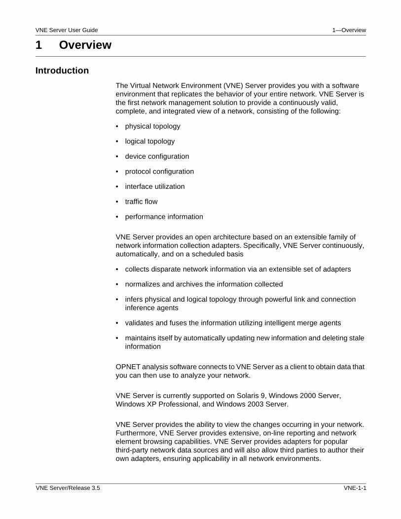
The Virtual Network Environment (VNE) Server provides you with a software environment that replicates the behavior of your entire network. VNE Server is the first network management solution to provide a continuously valid, complete, and integrated view of a network, consisting of the following:
• physical topology
• logical topology
• device configuration
• protocol configuration
• interface utilization
• traffic flow
• performance information
VNE Server provides an open architecture based on an extensible family of network information collection adapters. Specifically, VNE Server continuously, automatically, and on a scheduled basis
• collects disparate network information via an extensible set of adapters
• normalizes and archives the information collected
• infers physical and logical topology through powerful link and connection inference agents
• validates and fuses the information utilizing intelligent merge agents
• maintains itself by automatically updating new information and deleting stale information
OPNET analysis software connects to VNE Server as a client to obtain data that you can then use to analyze your network.
VNE Server is currently supported on Solaris 9, Windows 2000 Server, Windows XP Professional, and Windows 2003 Server.
VNE Server provides the ability to view the changes occurring in your network. Furthermore, VNE Server provides extensive, on-line reporting and network element browsing capabilities. VNE Server provides adapters for popular third-party network data sources and will also allow third parties to author their own adapters, ensuring applicability in all network environments.
VNE Server/Release 3.5 VNE-1-1
1—Overview VNE Server User Guide
The VNE Server adapter set includes network data collection from
• network management applications
• performance management applications
• traffic measurement applications
• device configuration files
• device SNMP MIBs
• device console commands
• proprietary information sources
• simple ASCII csv files
VNE-1-2 VNE Server/Release 3.5
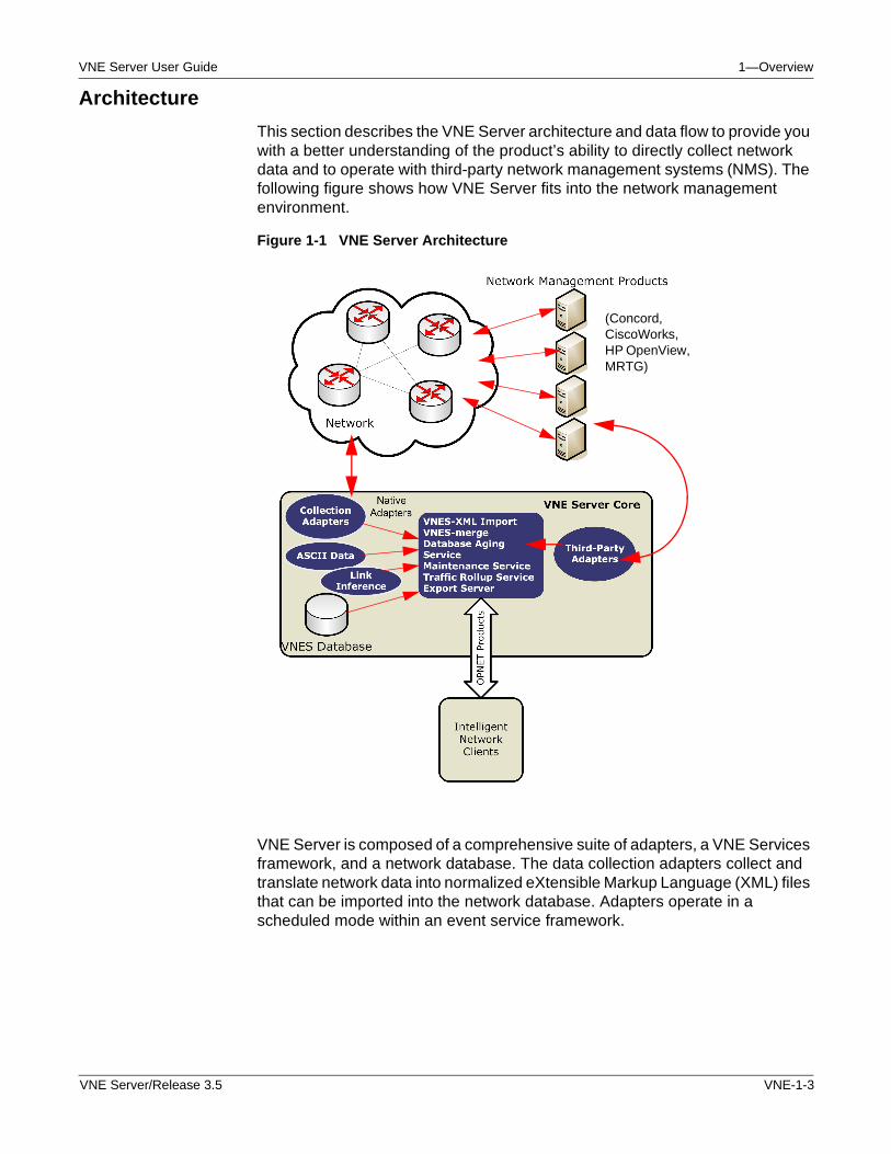
VNE Server User Guide 1—Overview
Architecture
This section describes the VNE Server architecture and data flow to provide you with a better understanding of the product’s ability to directly collect network data and to operate with third-party network management systems (NMS). The following figure shows how VNE Server fits into the network management environment.
Figure 1-1 VNE Server Architecture
VNE Server is composed of a comprehensive suite of adapters, a VNE Services framework, and a network database. The data collection adapters collect and translate network data into normalized eXtensible Markup Language (XML) files that can be imported into the network database. Adapters operate in a scheduled mode within an event service framework.
(Concord, CiscoWorks, HP OpenView, MRTG)
VNE Server/Release 3.5 VNE-1-3
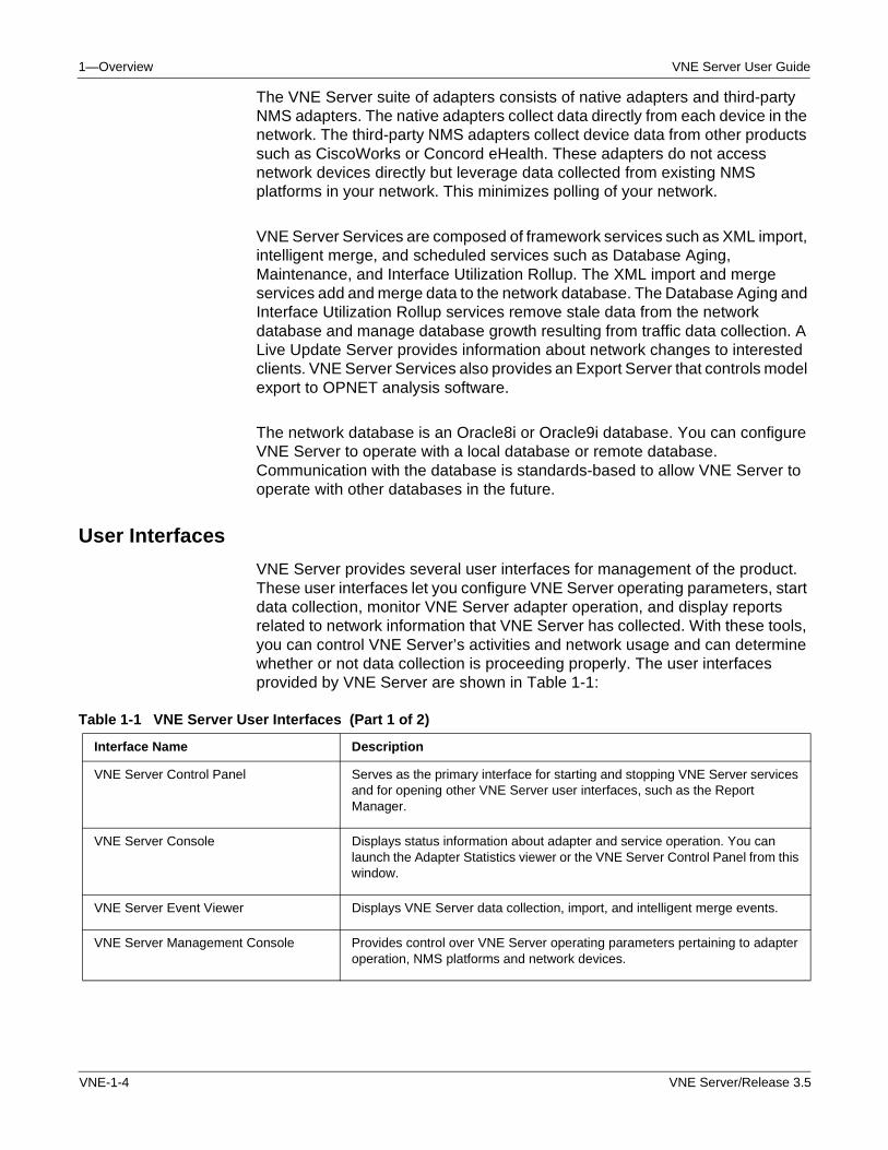
1—Overview VNE Server User Guide
The VNE Server suite of adapters consists of native adapters and third-party NMS adapters. The native adapters collect data directly from each device in the network. The third-party NMS adapters collect device data from other products such as CiscoWorks or Concord eHealth. These adapters do not access network devices directly but leverage data collected from existing NMS platforms in your network. This minimizes polling of your network.
VNE Server Services are composed of framework services such as XML import, intelligent merge, and scheduled services such as Database Aging, Maintenance, and Interface Utilization Rollup. The XML import and merge services add and merge data to the network database. The Database Aging and Interface Utilization Rollup services remove stale data from the network database and manage database growth resulting from traffic data collection. A Live Update Server provides information about network changes to interested clients. VNE Server Services also provides an Export Server that controls model export to OPNET analysis software.
The network database is an Oracle8i or Oracle9i database. You can configure VNE Server to operate with a local database or remote database. Communication with the database is standards-based to allow VNE Server to operate with other databases in the future.
User Interfaces
VNE Server provides several user interfaces for management of the product. These user interfaces let you configure VNE Server operating parameters, start data collection, monitor VNE Server adapter operation, and display reports related to network information that VNE Server has collected. With these tools, you can control VNE Server’s activities and network usage and can determine whether or not data collection is proceeding properly. The user interfaces provided by VNE Server are shown in Table 1-1:
Table 1-1 VNE Server User Interfaces (Part 1 of 2)
Interface Name Description
VNE Server Control Panel Serves as the primary interface for starting and stopping VNE Server services and for opening other VNE Server user interfaces, such as the Report Manager.
VNE Server Console Displays status information about adapter and service operation. You can launch the Adapter Statistics viewer or the VNE Server Control Panel from this window.
VNE Server Event Viewer Displays VNE Server data collection, import, and intelligent merge events.
VNE Server Management Console Provides control over VNE Server operating parameters pertaining to adapter operation, NMS platforms and network devices.
VNE-1-4 VNE Server/Release 3.5
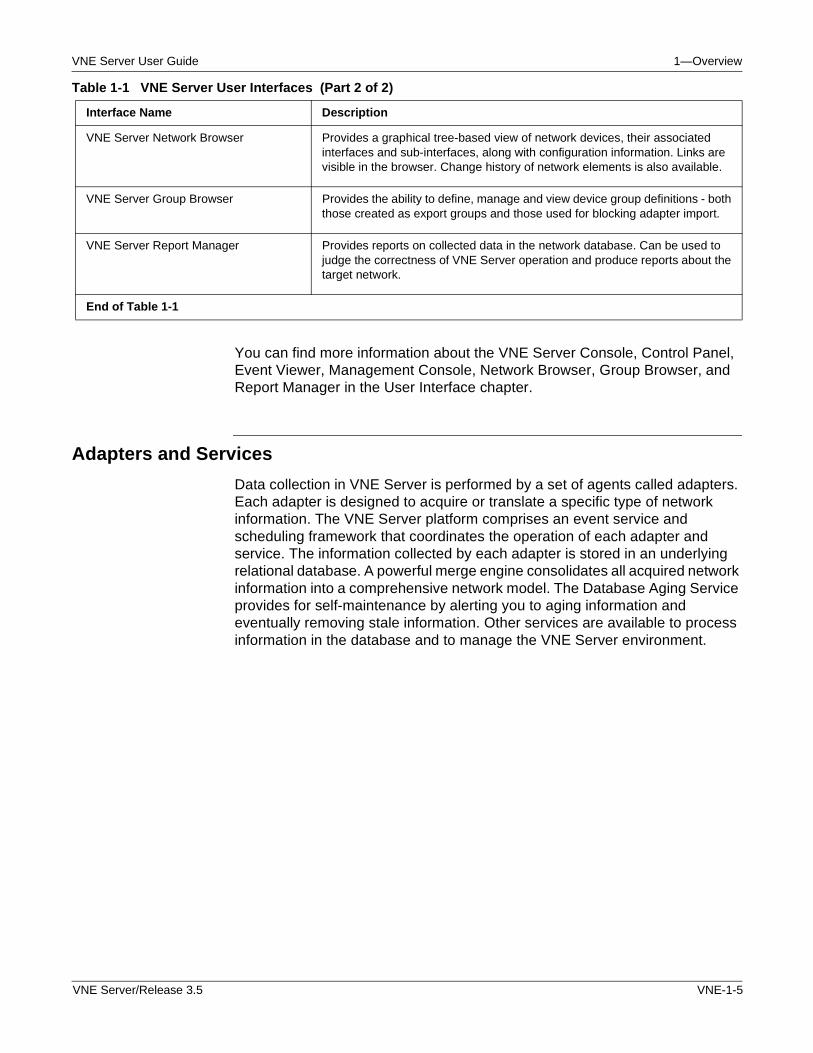
VNE Server User Guide 1—Overview
You can find more information about the VNE Server Console, Control Panel, Event Viewer, Management Console, Network Browser, Group Browser, and Report Manager in the User Interface chapter.
Adapters and Services
Data collection in VNE Server is performed by a set of agents called adapters. Each adapter is designed to acquire or translate a specific type of network information. The VNE Server platform comprises an event service and scheduling framework that coordinates the operation of each adapter and service. The information collected by each adapter is stored in an underlying relational database. A powerful merge engine consolidates all acquired network information into a comprehensive network model. The Database Aging Service provides for self-maintenance by alerting you to aging information and eventually removing stale information. Other services are available to process information in the database and to manage the VNE Server environment.
VNE Server Network Browser Provides a graphical tree-based view of network devices, their associated interfaces and sub-interfaces, along with configuration information. Links are visible in the browser. Change history of network elements is also available.
VNE Server Group Browser Provides the ability to define, manage and view device group definitions - both those created as export groups and those used for blocking adapter import.
VNE Server Report Manager Provides reports on collected data in the network database. Can be used to judge the correctness of VNE Server operation and produce reports about the target network.
End of Table 1-1
Table 1-1 VNE Server User Interfaces (Part 2 of 2)
Interface Name Description
VNE Server/Release 3.5 VNE-1-5
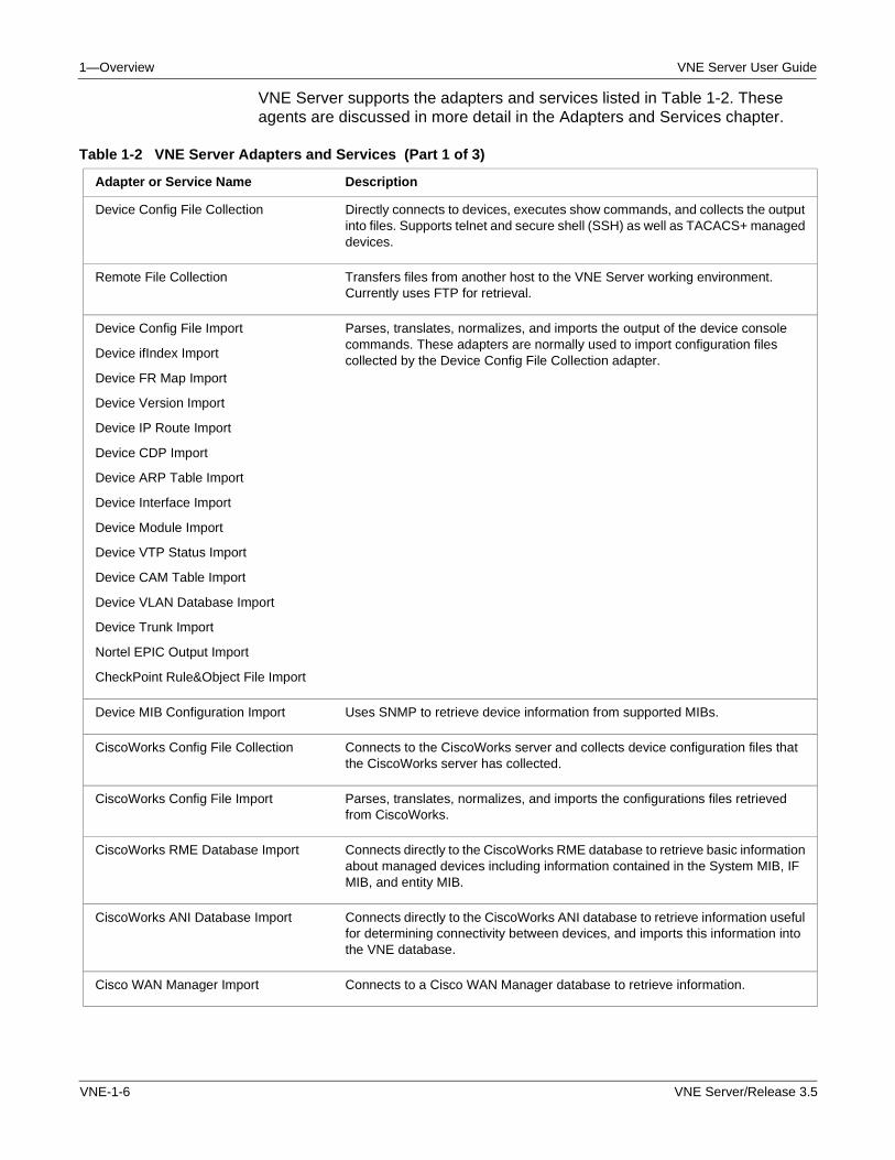
1—Overview VNE Server User Guide
VNE Server supports the adapters and services listed in Table 1-2. These agents are discussed in more detail in the Adapters and Services chapter.
Table 1-2 VNE Server Adapters and Services (Part 1 of 3)
Adapter or Service Name Description
Device Config File Collection Directly connects to devices, executes show commands, and collects the output into files. Supports telnet and secure shell (SSH) as well as TACACS+ managed devices.
Remote File Collection Transfers files from another host to the VNE Server working environment. Currently uses FTP for retrieval.
Device Config File Import
Device ifIndex Import
Device FR Map Import
Device Version Import
Device IP Route Import
Device CDP Import
Device ARP Table Import
Device Interface Import
Device Module Import
Device VTP Status Import
Device CAM Table Import
Device VLAN Database Import
Device Trunk Import
Nortel EPIC Output Import
CheckPoint Rule&Object File Import
Parses, translates, normalizes, and imports the output of the device console commands. These adapters are normally used to import configuration files collected by the Device Config File Collection adapter.
Device MIB Configuration Import Uses SNMP to retrieve device information from supported MIBs.
CiscoWorks Config File Collection Connects to the CiscoWorks server and collects device configuration files that the CiscoWorks server has collected.
CiscoWorks Config File Import Parses, translates, normalizes, and imports the configurations files retrieved from CiscoWorks.
CiscoWorks RME Database Import Connects directly to the CiscoWorks RME database to retrieve basic information about managed devices including information contained in the System MIB, IF MIB, and entity MIB.
CiscoWorks ANI Database Import Connects directly to the CiscoWorks ANI database to retrieve information useful for determining connectivity between devices, and imports this information into the VNE database.
Cisco WAN Manager Import Connects to a Cisco WAN Manager database to retrieve information.
VNE-1-6 VNE Server/Release 3.5
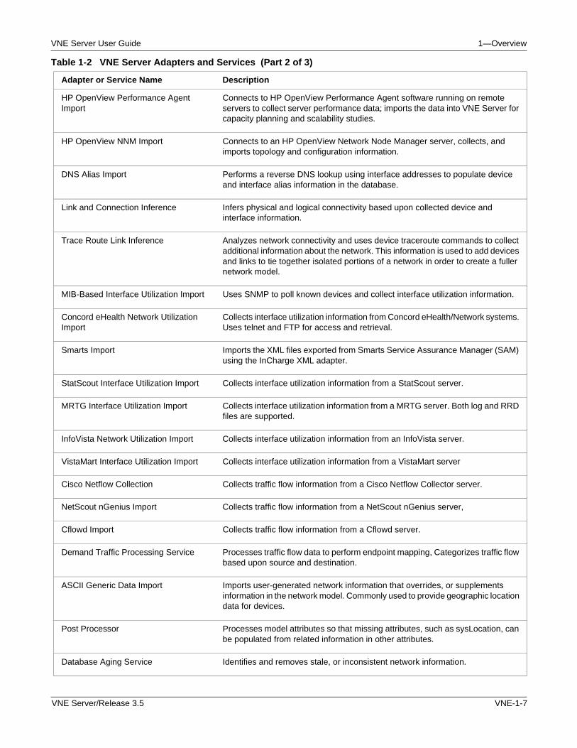
VNE Server User Guide 1—Overview
HP OpenView Performance Agent Import
Connects to HP OpenView Performance Agent software running on remote servers to collect server performance data; imports the data into VNE Server for capacity planning and scalability studies.
HP OpenView NNM Import Connects to an HP OpenView Network Node Manager server, collects, and imports topology and configuration information.
DNS Alias Import Performs a reverse DNS lookup using interface addresses to populate device and interface alias information in the database.
Link and Connection Inference Infers physical and logical connectivity based upon collected device and interface information.
Trace Route Link Inference Analyzes network connectivity and uses device traceroute commands to collect additional information about the network. This information is used to add devices and links to tie together isolated portions of a network in order to create a fuller network model.
MIB-Based Interface Utilization Import Uses SNMP to poll known devices and collect interface utilization information.
Concord eHealth Network Utilization Import
Collects interface utilization information from Concord eHealth/Network systems. Uses telnet and FTP for access and retrieval.
Smarts Import Imports the XML files exported from Smarts Service Assurance Manager (SAM) using the InCharge XML adapter.
StatScout Interface Utilization Import Collects interface utilization information from a StatScout server.
MRTG Interface Utilization Import Collects interface utilization information from a MRTG server. Both log and RRD files are supported.
InfoVista Network Utilization Import Collects interface utilization information from an InfoVista server.
VistaMart Interface Utilization Import Collects interface utilization information from a VistaMart server
Cisco Netflow Collection Collects traffic flow information from a Cisco Netflow Collector server.
NetScout nGenius Import Collects traffic flow information from a NetScout nGenius server,
Cflowd Import Collects traffic flow information from a Cflowd server.
Demand Traffic Processing Service Processes traffic flow data to perform endpoint mapping, Categorizes traffic flow based upon source and destination.
ASCII Generic Data Import Imports user-generated network information that overrides, or supplements information in the network model. Commonly used to provide geographic location data for devices.
Post Processor Processes model attributes so that missing attributes, such as sysLocation, can be populated from related information in other attributes.
Database Aging Service Identifies and removes stale, or inconsistent network information.
Table 1-2 VNE Server Adapters and Services (Part 2 of 3)
Adapter or Service Name Description
VNE Server/Release 3.5 VNE-1-7
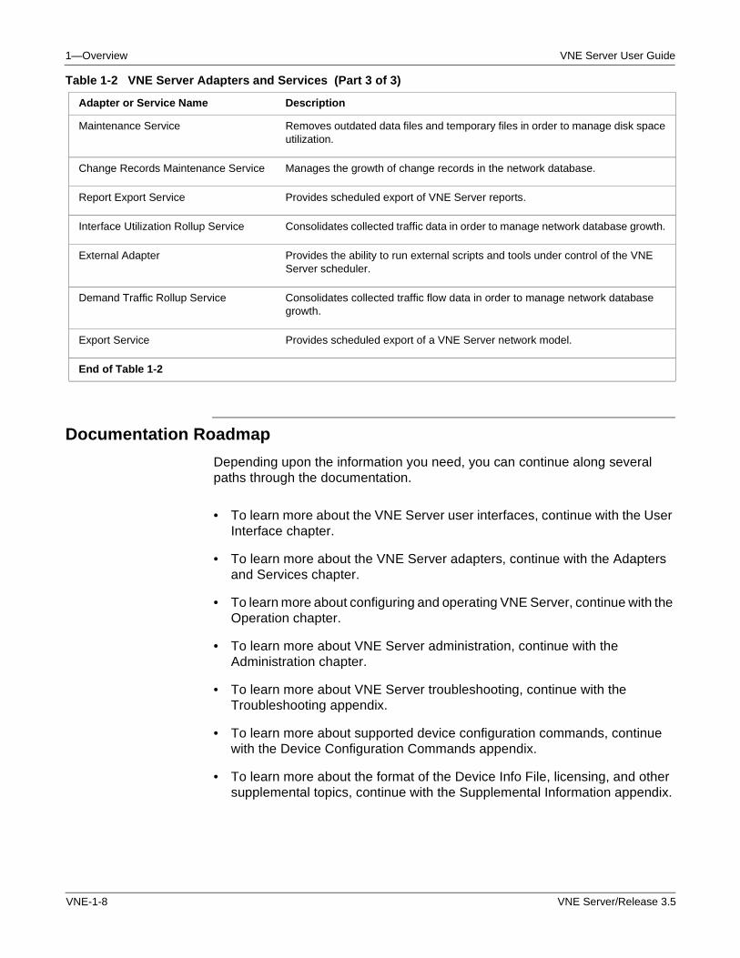
1—Overview VNE Server User Guide
Documentation Roadmap
Depending upon the information you need, you can continue along several paths through the documentation.
• To learn more about the VNE Server user interfaces, continue with the User Interface chapter.
• To learn more about the VNE Server adapters, continue with the Adapters and Services chapter.
• To learn more about configuring and operating VNE Server, continue with the Operation chapter.
• To learn more about VNE Server administration, continue with the Administration chapter.
• To learn more about VNE Server troubleshooting, continue with the Troubleshooting appendix.
• To learn more about supported device configuration commands, continue with the Device Configuration Commands appendix.
• To learn more about the format of the Device Info File, licensing, and other supplemental topics, continue with the Supplemental Information appendix.
Maintenance Service Removes outdated data files and temporary files in order to manage disk space utilization.
Change Records Maintenance Service Manages the growth of change records in the network database.
Report Export Service Provides scheduled export of VNE Server reports.
Interface Utilization Rollup Service Consolidates collected traffic data in order to manage network database growth.
External Adapter Provides the ability to run external scripts and tools under control of the VNE Server scheduler.
Demand Traffic Rollup Service Consolidates collected traffic flow data in order to manage network database growth.
Export Service Provides scheduled export of a VNE Server network model.
End of Table 1-2
Table 1-2 VNE Server Adapters and Services (Part 3 of 3)
Adapter or Service Name Description
VNE-1-8 VNE Server/Release 3.5
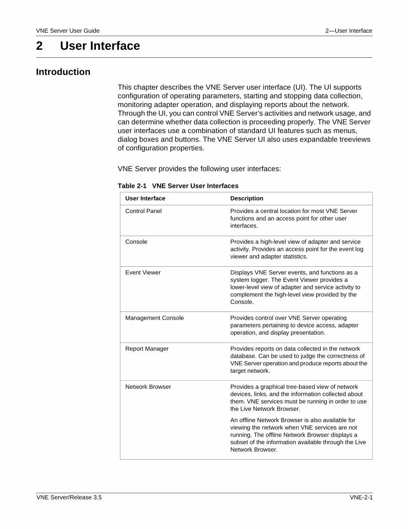
VNE Server User Guide 2—User Interface
2 User Interface
Introduction
This chapter describes the VNE Server user interface (UI). The UI supports configuration of operating parameters, starting and stopping data collection, monitoring adapter operation, and displaying reports about the network. Through the UI, you can control VNE Server’s activities and network usage, and can determine whether data collection is proceeding properly. The VNE Server user interfaces use a combination of standard UI features such as menus, dialog boxes and buttons. The VNE Server UI also uses expandable treeviews of configuration properties.
VNE Server provides the following user interfaces:
Table 2-1 VNE Server User Interfaces
User Interface Description
Control Panel Provides a central location for most VNE Server functions and an access point for other user interfaces.
Console Provides a high-level view of adapter and service activity. Provides an access point for the event log viewer and adapter statistics.
Event Viewer Displays VNE Server events, and functions as a system logger. The Event Viewer provides a lower-level view of adapter and service activity to complement the high-level view provided by the Console.
Management Console Provides control over VNE Server operating parameters pertaining to device access, adapter operation, and display presentation.
Report Manager Provides reports on data collected in the network database. Can be used to judge the correctness of VNE Server operation and produce reports about the target network.
Network Browser Provides a graphical tree-based view of network devices, links, and the information collected about them. VNE services must be running in order to use the Live Network Browser.
An offline Network Browser is also available for viewing the network when VNE services are not running. The offline Network Browser displays a subset of the information available through the Live Network Browser.
VNE Server/Release 3.5 VNE-2-1
2—User Interface VNE Server User Guide
The VNE Server Program Group
VNE Server is launched from the OPNET VNE Server 3.5 program group. This program group provides the selections shown in the following table:
Note—You must be logged in as Administrator for the VNE Server program group to be visible.
Starting VNE Server
Procedure 2-1 describes how to start VNE Server from the program group.
Procedure 2-1 Starting VNE Server
1 Choose Start > Programs.
2 Locate the OPNET VNE Server 3.5 program group.
3 Choose OPNET VNE Server from the OPNET VNE Server 3.5 program group.
➥ Within a minute, the VNE Server Console opens.
End of Procedure 2-1
Note—If you are running VNE Server on Windows XP and have a white menu bar in the application window, change the theme from Windows XP to Windows Classic. You can change the theme in the Display panel by opening the Windows OS Control Panel > Display.
Table 2-2 VNE Server Program Group Selections
Selection Function
Open File Log Viewer Opens the VNE Server File Log Viewer.
Open Licensing Web Page Opens a web browser to the OPNET License Registration page.
OPNET VNE Server Documentation
Opens the VNE Server documentation menu in Acrobat Reader.
OPNET VNE Server Opens the VNE Server Console.
End of Table 2-2
VNE-2-2 VNE Server/Release 3.5
VNE Server User Guide 2—User Interface
Viewing VNE Server Documentation
To open the VNE Server documentation set, follow the steps in Procedure 2-2:
Procedure 2-2 Open VNE Server Documentation
1 Choose Start > Programs.
2 Locate the OPNET VNE Server 3.5 program group.
3 Choose the OPNET VNE Server documentation item from the OPNET VNE Server program group.
➥ Acrobat Reader opens and shows the VNE Server documentation menu.
End of Procedure 2-2
Viewing Event Log Files
Procedure 2-3 describes how to view the VNE Server event log file.
Procedure 2-3 Viewing the VNE Server Event Log:
1 Choose Start > Programs.
2 Locate the OPNET VNE Server 3.5 program group.
3 Choose the Open File Log Viewer item from the OPNET VNE Server program group.
➥ A file selection browser opens and displays a list of event log files that exist in the VNE Server environment.
4 Choose the event log file to open, and press Select.
➥ An Event Viewer window opens and displays the contents of the event log file.
End of Procedure 2-3
Opening the OPNET Licensing Web Page
You can open the OPNET licensing web page directly from the program group using the steps in Procedure 2-4.
Procedure 2-4 Opening the OPNET LIcensing Web Page
1 Choose Start > Programs.
2 Locate the OPNET VNE Server 3.5 program group.
VNE Server/Release 3.5 VNE-2-3
2—User Interface VNE Server User Guide
3 Choose the Open Licensing Web Page item from the OPNET VNE Server program group.
➥ The default web browser opens and displays the OPNET License Registration web page.
End of Procedure 2-4
VNE Server Commands on Solaris
For VNE Server on a Solaris Platform, the major functions described in the previous section are executed as follows.
Starting VNE Server
Change your working directory to the VNE Server installation directory on Solaris. Enter the following command to start VNE Server:
vnes.sh -r Oracle9i EV
Deleting the Current Project
Change your working directory to the VNE Server installation directory on Solaris. Enter the following command to delete the current project within the database:
vnes.sh -r Oracle9i CLEANDB
WARNING—This command permanently removes all data for the current project from the database.
Deleting All Projects and Tables
Change your working directory to the VNE Server installation directory on Solaris. Enter the following command to delete all the projects and tables in the database:
vnes.sh -r Oracle9i CLEANALLDB
This command leaves the user account and tablespace files intact but removes all tables, synonyms, and projects owned by this user from the database. Use the CLEANALLDB command when upgrading to a new build that changes the table schema. Running CLEANALLDB allows the new build to reinitialize the database without re-running the setup_accounts SQL script.
VNE-2-4 VNE Server/Release 3.5
VNE Server User Guide 2—User Interface
This command target also exists for Windows users.
WARNING—This command permanently removes ALL data for ALL VNE Server projects from the database.
Deleting the Temporary Directory and Current Project
Change your working directory to the VNE Server installation directory on Solaris. Enter the following command to delete the temp dir and the current project in the database:
vnes.sh -r Oracle9i CLEANALL
WARNING—This command will permanently remove all data for the current project from the database.
Viewing VNE Server Documentation
Change your working directory to the VNE Server installation directory on Solaris. Enter the following command to view documentation:
vnes.sh -r Oracle9i HELP
Viewing Event Log Files
Change your working directory to the VNE Server installation directory on Solaris. Enter the following command to view an event log file:
vnes.sh -r Oracle9i FV
Performing License Operations
Refer to the Product Licensing on page VNE-5-12 section of the Administration chapter for command line licensing procedures for VNE Server on Solaris.
Control Panel
The Control Panel is the most visible component of VNE Server and is the UI that you see after starting the product. From the Control Panel, you can start and stop data collection services, monitor the status of adapter and service execution, and open the other UIs provided by VNE Server. You can access the following menus from the Control Panel:
• File Menu
• Services Menu
• Configuration Menu
VNE Server/Release 3.5 VNE-2-5
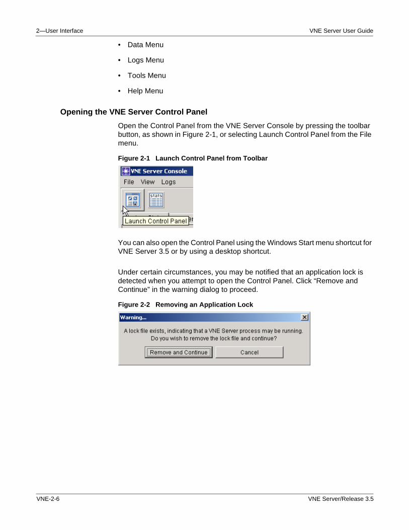
2—User Interface VNE Server User Guide
• Data Menu
• Logs Menu
• Tools Menu
• Help Menu
Opening the VNE Server Control Panel
Open the Control Panel from the VNE Server Console by pressing the toolbar button, as shown in Figure 2-1, or selecting Launch Control Panel from the File menu.
Figure 2-1 Launch Control Panel from Toolbar
You can also open the Control Panel using the Windows Start menu shortcut for VNE Server 3.5 or by using a desktop shortcut.
Under certain circumstances, you may be notified that an application lock is detected when you attempt to open the Control Panel. Click “Remove and Continue” in the warning dialog to proceed.
Figure 2-2 Removing an Application Lock
VNE-2-6 VNE Server/Release 3.5
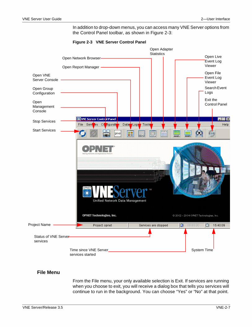
VNE Server User Guide 2—User Interface
In addition to drop-down menus, you can access many VNE Server options from the Control Panel toolbar, as shown in Figure 2-3:
Figure 2-3 VNE Server Control Panel
File Menu
From the File menu, your only available selection is Exit. If services are running when you choose to exit, you will receive a dialog box that tells you services will continue to run in the background. You can choose “Yes” or “No” at that point.
Start Services
Stop Services
Open Management Console
Open Group Configuration
Open VNE Server Console
Open Report Manager
Exit the Control Panel
Search Event Logs
Open File Event Log Viewer
Open Network Browser Open Live Event Log Viewer
Open Adapter Statistics
Project Name
Status of VNE Server services
Time since VNE Server services started
System Time
VNE Server/Release 3.5 VNE-2-7
2—User Interface VNE Server User Guide
Services Menu
You can start or stop VNE Server services from the Services menu or from the toolbar buttons. The status of VNE Server services is visible on the Control Panel toolbar, as shown in Figure 2-3. If you position your cursor over the services information, a tooltip appears, displaying the status of each service.
VNE Server services include
• OPNET VNES Adapter Server
• OPNET VNES Bootstrap Service
• OPNET VNES Common Services
• OPNET VNES Export Server
• OPNET VNES Live Update Server
You can observe and configure these services through Windows’ Administrative Tools > Services menu.
WARNING—It is strongly recommended that you configure Windows Automatic Update service on the VNE Server host to notify you when updates are ready to install, rather than permitting updates to be installed automatically. When Windows Automatic Update service installs updates automatically, the update service may reboot the machine following the update and interrupt VNE Server operation.
Starting VNE Server Services
When you start VNE Server services, OPNET VNES Common Services stops and restarts to pick up changes in the adapter schedule and adapter resources. Next, the Export Server, Live Update Server, and Adapter Server start.
Stopping VNE Server Services
When you stop VNE Server services, services stop as follows: Export Server, Live Update Server, then Adapter Server.
Status of VNE Server Services
The VNE Server toolbar, shown in Figure 2-3, provides a visual clue as to the status of VNE Server services. When services are started, the Start Services button is not operational. Likewise, when services are stopped, the Stop Services button is not operational.
VNE-2-8 VNE Server/Release 3.5
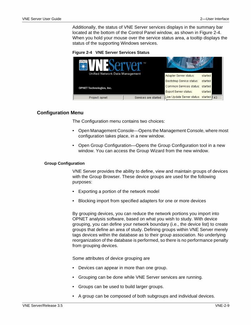
VNE Server User Guide 2—User Interface
Additionally, the status of VNE Server services displays in the summary bar located at the bottom of the Control Panel window, as shown in Figure 2-4. When you hold your mouse over the service status area, a tooltip displays the status of the supporting Windows services.
Figure 2-4 VNE Server Services Status
Configuration Menu
The Configuration menu contains two choices:
• Open Management Console—Opens the Management Console, where most configuration takes place, in a new window.
• Open Group Configuration—Opens the Group Configuration tool in a new window. You can access the Group Wizard from the new window.
Group Configuration
VNE Server provides the ability to define, view and maintain groups of devices with the Group Browser. These device groups are used for the following purposes:
• Exporting a portion of the network model
• Blocking import from specified adapters for one or more devices
By grouping devices, you can reduce the network portions you import into OPNET analysis software, based on what you wish to study. With device grouping, you can define your network boundary (i.e., the device list) to create groups that define an area of study. Defining groups within VNE Server merely tags devices within the database as to their group association. No underlying reorganization of the database is performed, so there is no performance penalty from grouping devices.
Some attributes of device grouping are
• Devices can appear in more than one group.
• Grouping can be done while VNE Server services are running.
• Groups can be used to build larger groups.
• A group can be composed of both subgroups and individual devices.
VNE Server/Release 3.5 VNE-2-9
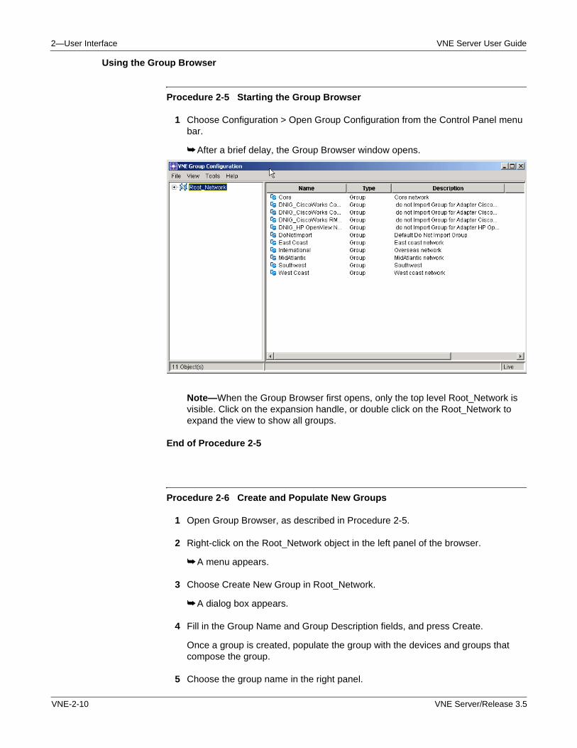
2—User Interface VNE Server User Guide
Using the Group Browser
Procedure 2-5 Starting the Group Browser
1 Choose Configuration > Open Group Configuration from the Control Panel menu bar.
➥ After a brief delay, the Group Browser window opens.
Note—When the Group Browser first opens, only the top level Root_Network is visible. Click on the expansion handle, or double click on the Root_Network to expand the view to show all groups.
End of Procedure 2-5
Procedure 2-6 Create and Populate New Groups
1 Open Group Browser, as described in Procedure 2-5.
2 Right-click on the Root_Network object in the left panel of the browser.
➥ A menu appears.
3 Choose Create New Group in Root_Network.
➥ A dialog box appears.
4 Fill in the Group Name and Group Description fields, and press Create.
Once a group is created, populate the group with the devices and groups that compose the group.
5 Choose the group name in the right panel.
VNE-2-10 VNE Server/Release 3.5
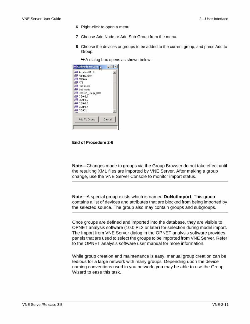
VNE Server User Guide 2—User Interface
6 Right-click to open a menu.
7 Choose Add Node or Add Sub-Group from the menu.
8 Choose the devices or groups to be added to the current group, and press Add to Group.
➥ A dialog box opens as shown below.
End of Procedure 2-6
Note—Changes made to groups via the Group Browser do not take effect until the resulting XML files are imported by VNE Server. After making a group change, use the VNE Server Console to monitor import status.
Note—A special group exists which is named DoNotImport. This group contains a list of devices and attributes that are blocked from being imported by the selected source. The group also may contain groups and subgroups.
Once groups are defined and imported into the database, they are visible to OPNET analysis software (10.0 PL2 or later) for selection during model import. The Import from VNE Server dialog in the OPNET analysis software provides panels that are used to select the groups to be imported from VNE Server. Refer to the OPNET analysis software user manual for more information.
While group creation and maintenance is easy, manual group creation can be tedious for a large network with many groups. Depending upon the device naming conventions used in you network, you may be able to use the Group Wizard to ease this task.
VNE Server/Release 3.5 VNE-2-11
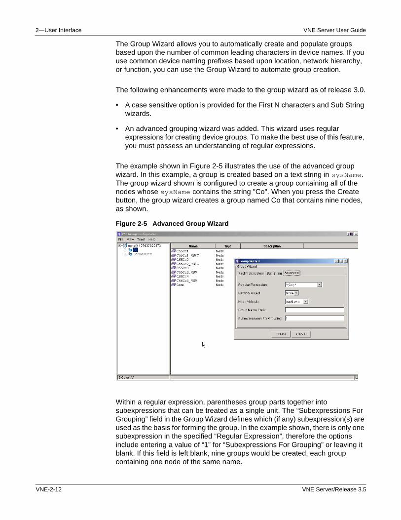
2—User Interface VNE Server User Guide
The Group Wizard allows you to automatically create and populate groups based upon the number of common leading characters in device names. If you use common device naming prefixes based upon location, network hierarchy, or function, you can use the Group Wizard to automate group creation.
The following enhancements were made to the group wizard as of release 3.0.
• A case sensitive option is provided for the First N characters and Sub String wizards.
• An advanced grouping wizard was added. This wizard uses regular expressions for creating device groups. To make the best use of this feature, you must possess an understanding of regular expressions.
The example shown in Figure 2-5 illustrates the use of the advanced group wizard. In this example, a group is created based on a text string in sysName. The group wizard shown is configured to create a group containing all of the nodes whose sysName contains the string "Co". When you press the Create button, the group wizard creates a group named Co that contains nine nodes, as shown.
Figure 2-5 Advanced Group Wizard
Within a regular expression, parentheses group parts together into subexpressions that can be treated as a single unit. The “Subexpressions For Grouping” field in the Group Wizard defines which (if any) subexpression(s) are used as the basis for forming the group. In the example shown, there is only one subexpression in the specified “Regular Expression”, therefore the options include entering a value of “1” for “Subexpressions For Grouping” or leaving it blank. If this field is left blank, nine groups would be created, each group containing one node of the same name.
VNE-2-12 VNE Server/Release 3.5
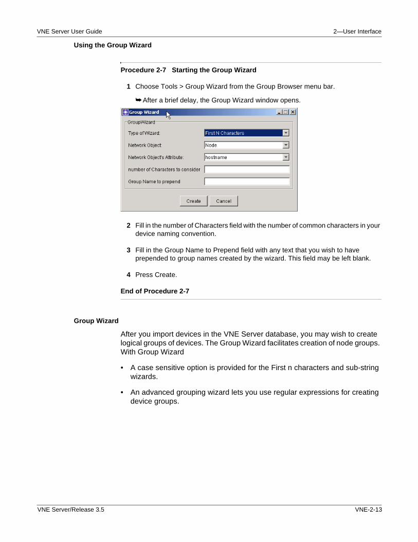
VNE Server User Guide 2—User Interface
Using the Group Wizard
Procedure 2-7 Starting the Group Wizard
1 Choose Tools > Group Wizard from the Group Browser menu bar.
➥ After a brief delay, the Group Wizard window opens.
2 Fill in the number of Characters field with the number of common characters in your device naming convention.
3 Fill in the Group Name to Prepend field with any text that you wish to have prepended to group names created by the wizard. This field may be left blank.
4 Press Create.
End of Procedure 2-7
Group Wizard
After you import devices in the VNE Server database, you may wish to create logical groups of devices. The Group Wizard facilitates creation of node groups. With Group Wizard
• A case sensitive option is provided for the First n characters and sub-string wizards.
• An advanced grouping wizard lets you use regular expressions for creating device groups.
VNE Server/Release 3.5 VNE-2-13
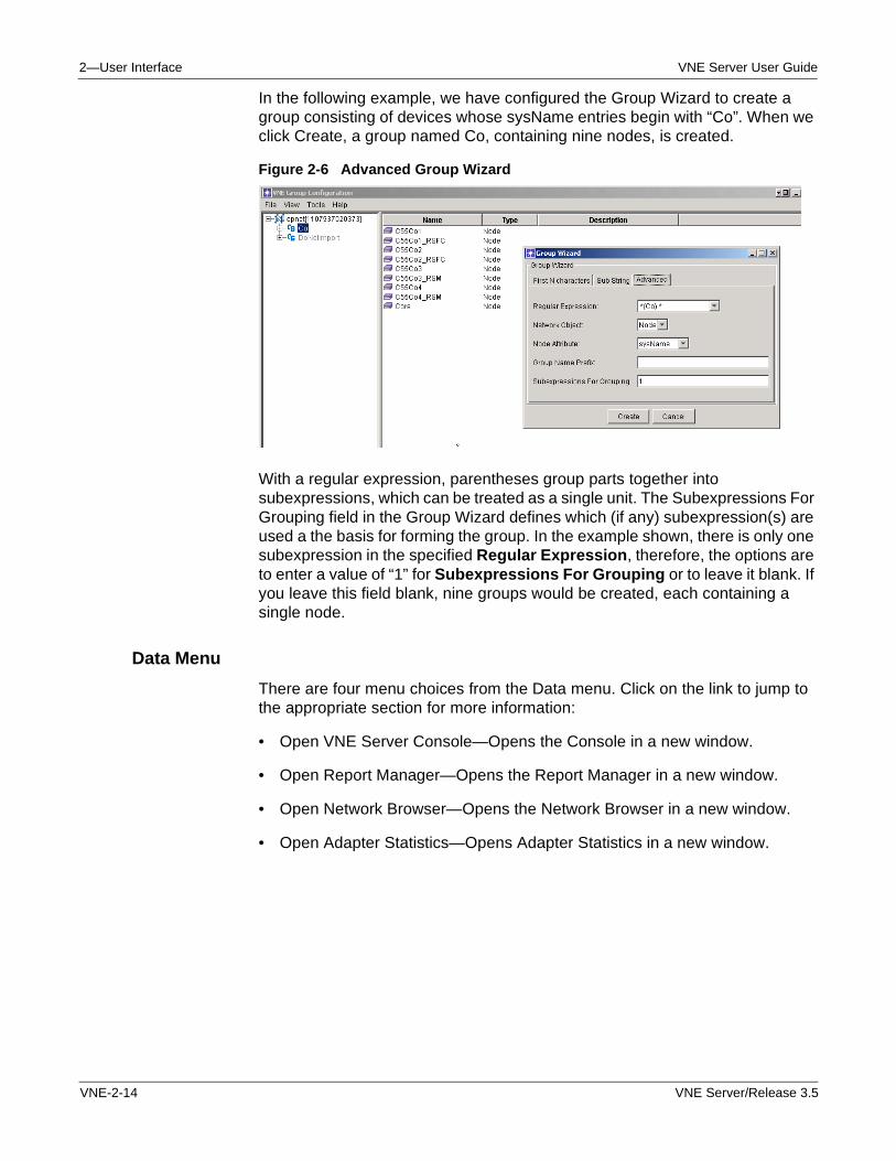
2—User Interface VNE Server User Guide
In the following example, we have configured the Group Wizard to create a group consisting of devices whose sysName entries begin with “Co”. When we click Create, a group named Co, containing nine nodes, is created.
Figure 2-6 Advanced Group Wizard
With a regular expression, parentheses group parts together into subexpressions, which can be treated as a single unit. The Subexpressions For Grouping field in the Group Wizard defines which (if any) subexpression(s) are used a the basis for forming the group. In the example shown, there is only one subexpression in the specified Regular Expression, therefore, the options are to enter a value of “1” for Subexpressions For Grouping or to leave it blank. If you leave this field blank, nine groups would be created, each containing a single node.
Data Menu
There are four menu choices from the Data menu. Click on the link to jump to the appropriate section for more information:
• Open VNE Server Console—Opens the Console in a new window.
• Open Report Manager—Opens the Report Manager in a new window.
• Open Network Browser—Opens the Network Browser in a new window.
• Open Adapter Statistics—Opens Adapter Statistics in a new window.
VNE-2-14 VNE Server/Release 3.5
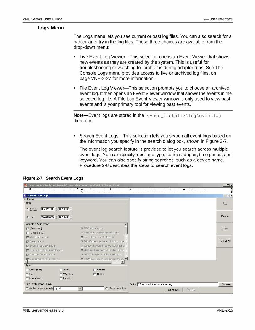
VNE Server User Guide 2—User Interface
Logs Menu
The Logs menu lets you see current or past log files. You can also search for a particular entry in the log files. These three choices are available from the drop-down menu:
• Live Event Log Viewer—This selection opens an Event Viewer that shows new events as they are created by the system. This is useful for troubleshooting or watching for problems during adapter runs. See The Console Logs menu provides access to live or archived log files. on page VNE-2-27 for more information.
• File Event Log Viewer—This selection prompts you to choose an archived event log. It then opens an Event Viewer window that shows the events in the selected log file. A File Log Event Viewer window is only used to view past events and is your primary tool for viewing past events.
Note—Event logs are stored in the <vnes_install>\log\eventlog directory.
• Search Event Logs—This selection lets you search all event logs based on the information you specify in the search dialog box, shown in Figure 2-7.
The event log search feature is provided to let you search across multiple event logs. You can specify message type, source adapter, time period, and keyword. You can also specify string searches, such as a device name. Procedure 2-8 describes the steps to search event logs.
Figure 2-7 Search Event Logs
VNE Server/Release 3.5 VNE-2-15
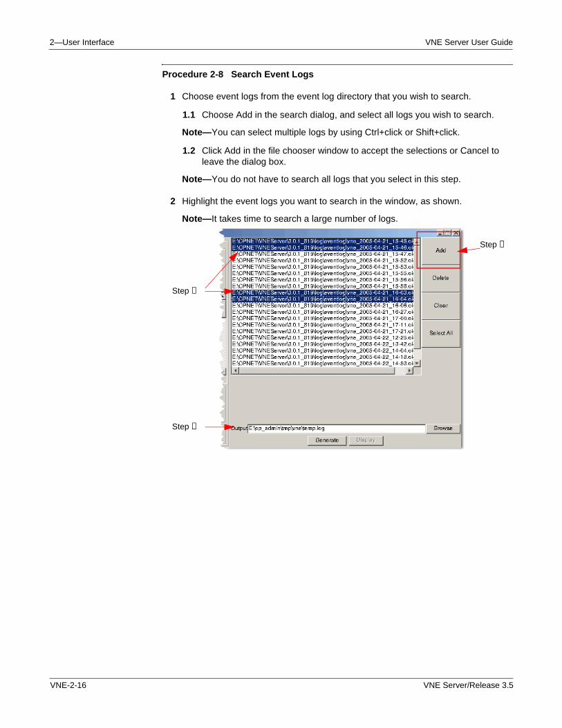
2—User Interface VNE Server User Guide
Procedure 2-8 Search Event Logs
1 Choose event logs from the event log directory that you wish to search.
1.1 Choose Add in the search dialog, and select all logs you wish to search.
Note—You can select multiple logs by using Ctrl+click or Shift+click.
1.2 Click Add in the file chooser window to accept the selections or Cancel to leave the dialog box.
Note—You do not have to search all logs that you select in this step.
2 Highlight the event logs you want to search in the window, as shown.
Note—It takes time to search a large number of logs.
Step ➊
Step ➋
Step ➎
VNE-2-16 VNE Server/Release 3.5
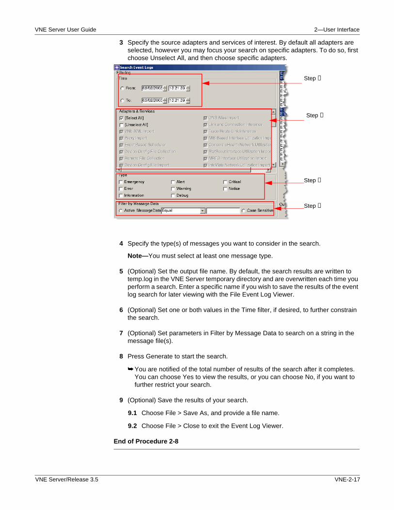
VNE Server User Guide 2—User Interface
3 Specify the source adapters and services of interest. By default all adapters are selected, however you may focus your search on specific adapters. To do so, first choose Unselect All, and then choose specific adapters.
4 Specify the type(s) of messages you want to consider in the search.
Note—You must select at least one message type.
5 (Optional) Set the output file name. By default, the search results are written to temp.log in the VNE Server temporary directory and are overwritten each time you perform a search. Enter a specific name if you wish to save the results of the event log search for later viewing with the File Event Log Viewer.
6 (Optional) Set one or both values in the Time filter, if desired, to further constrain the search.
7 (Optional) Set parameters in Filter by Message Data to search on a string in the message file(s).
8 Press Generate to start the search.
➥ You are notified of the total number of results of the search after it completes. You can choose Yes to view the results, or you can choose No, if you want to further restrict your search.
9 (Optional) Save the results of your search.
9.1 Choose File > Save As, and provide a file name.
9.2 Choose File > Close to exit the Event Log Viewer.
End of Procedure 2-8
Step ➍
Step ➌
Step ➏
Step ➐
VNE Server/Release 3.5 VNE-2-17
2—User Interface VNE Server User Guide
Tools Menu
From the Tools menu, you can
• Empty data from the current project
• Remove the temporary directory, and empty the current project
• Remove the archives directory and all records from the current project
Help Menu
From the Help menu of the VNE Server Control Panel, you can access
• VNE Server Help—Opens the menu to this document, release notes, installation notes, and technical support forms.
• About VNE Server—Opens a dialog box containing legal information and information about the version of VNE Server installed.
VNE-2-18 VNE Server/Release 3.5
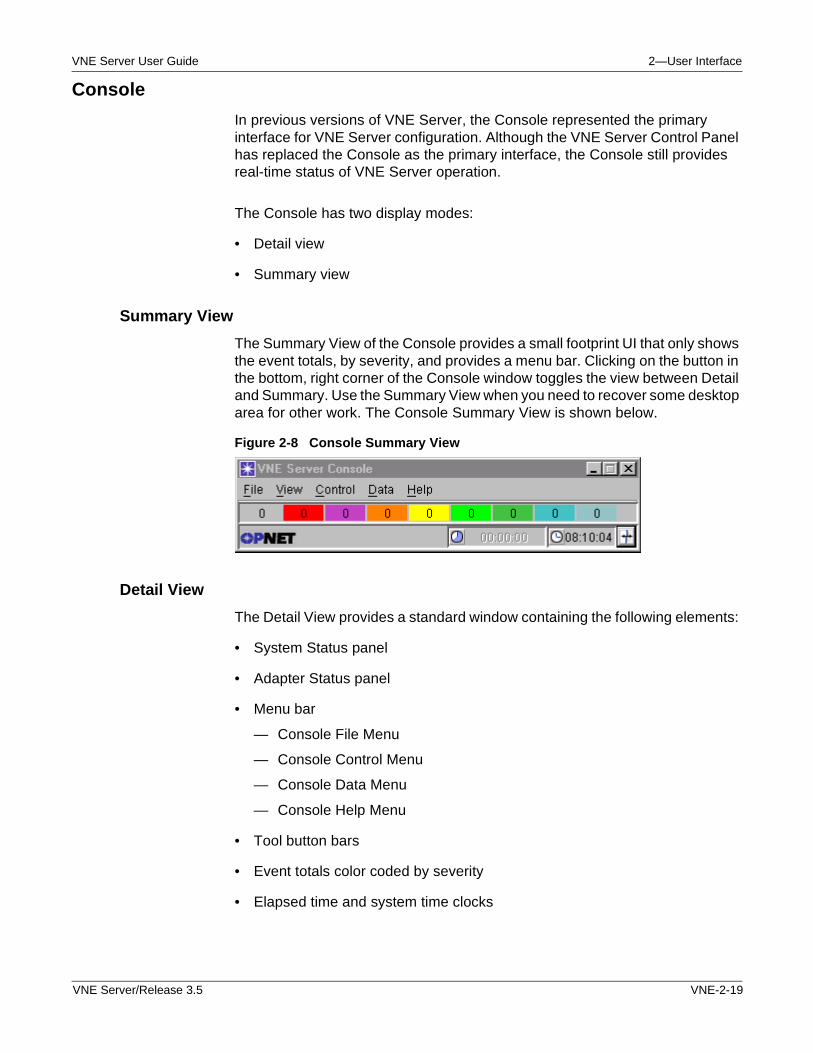
VNE Server User Guide 2—User Interface
Console
In previous versions of VNE Server, the Console represented the primary interface for VNE Server configuration. Although the VNE Server Control Panel has replaced the Console as the primary interface, the Console still provides real-time status of VNE Server operation.
The Console has two display modes:
• Detail view
• Summary view
Summary View
The Summary View of the Console provides a small footprint UI that only shows the event totals, by severity, and provides a menu bar. Clicking on the button in the bottom, right corner of the Console window toggles the view between Detail and Summary. Use the Summary View when you need to recover some desktop area for other work. The Console Summary View is shown below.
Figure 2-8 Console Summary View
Detail View
The Detail View provides a standard window containing the following elements:
• System Status panel
• Adapter Status panel
• Menu bar
— Console File Menu
— Console Control Menu
— Console Data Menu
— Console Help Menu
• Tool button bars
• Event totals color coded by severity
• Elapsed time and system time clocks
VNE Server/Release 3.5 VNE-2-19
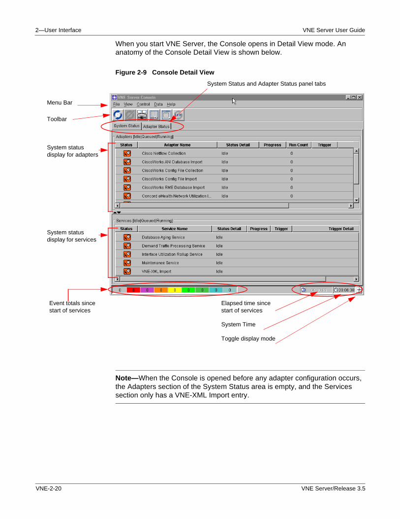
2—User Interface VNE Server User Guide
When you start VNE Server, the Console opens in Detail View mode. An anatomy of the Console Detail View is shown below.
Figure 2-9 Console Detail View
Note—When the Console is opened before any adapter configuration occurs, the Adapters section of the System Status area is empty, and the Services section only has a VNE-XML Import entry.
System Status and Adapter Status panel tabs
Menu Bar
Toolbar
System status display for adapters
System status display for services
Event totals since start of services
Elapsed time since start of services
System Time
Toggle display mode
VNE-2-20 VNE Server/Release 3.5
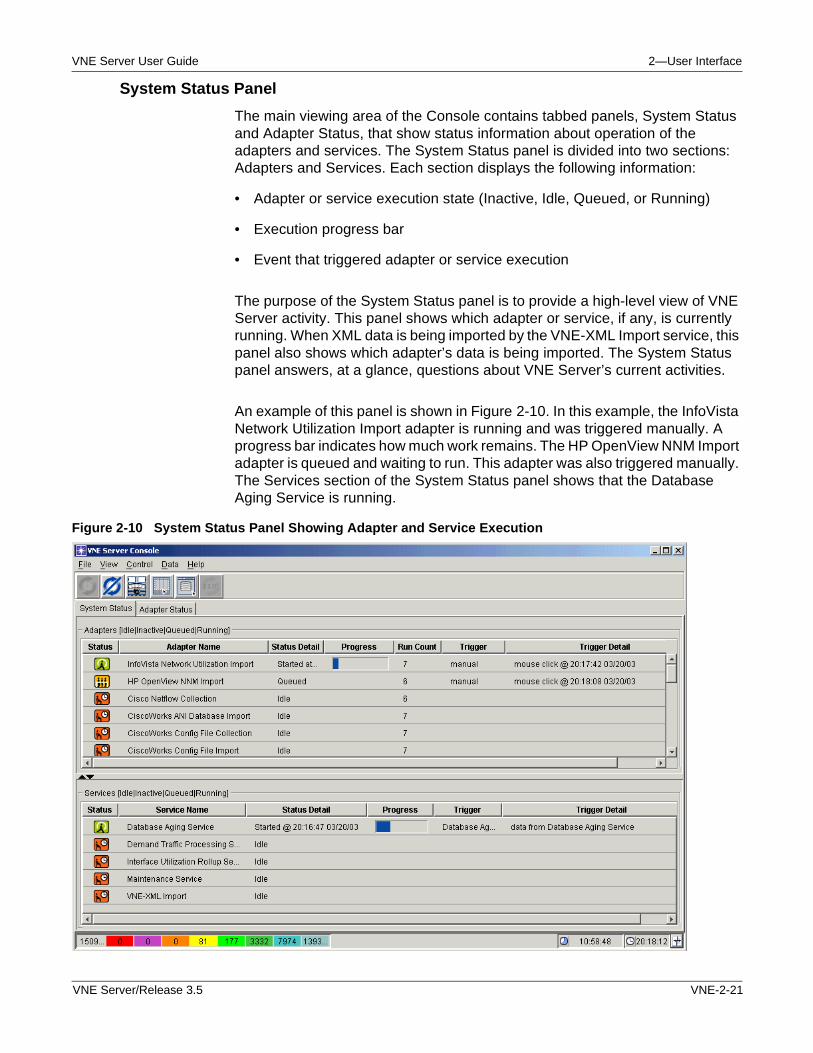
VNE Server User Guide 2—User Interface
System Status Panel
The main viewing area of the Console contains tabbed panels, System Status and Adapter Status, that show status information about operation of the adapters and services. The System Status panel is divided into two sections: Adapters and Services. Each section displays the following information:
• Adapter or service execution state (Inactive, Idle, Queued, or Running)
• Execution progress bar
• Event that triggered adapter or service execution
The purpose of the System Status panel is to provide a high-level view of VNE Server activity. This panel shows which adapter or service, if any, is currently running. When XML data is being imported by the VNE-XML Import service, this panel also shows which adapter’s data is being imported. The System Status panel answers, at a glance, questions about VNE Server’s current activities.
An example of this panel is shown in Figure 2-10. In this example, the InfoVista Network Utilization Import adapter is running and was triggered manually. A progress bar indicates how much work remains. The HP OpenView NNM Import adapter is queued and waiting to run. This adapter was also triggered manually. The Services section of the System Status panel shows that the Database Aging Service is running.
Figure 2-10 System Status Panel Showing Adapter and Service Execution
VNE Server/Release 3.5 VNE-2-21
2—User Interface VNE Server User Guide
Both sections of the System Status panel provide horizontal and vertical scroll bars when the data to be displayed exceeds the panel space. In both the System Status and Adapter Status panels, columns can be resized by dragging the borders and can be repositioned by dragging the column header.
Adapters and services that are in a Running or Queued state move to the top of the status sections.
Adapter Status Panel
The Adapter Status panel provides more details about adapter operation to complement the high-level view provided by the System Status panel. The Adapter Status panel provides the following information about adapter operation:
• Start time, end time, and duration of previous adapter run
• Trigger event and details of previous adapter run
• Trigger event and details of the next adapter run
VNE-2-22 VNE Server/Release 3.5
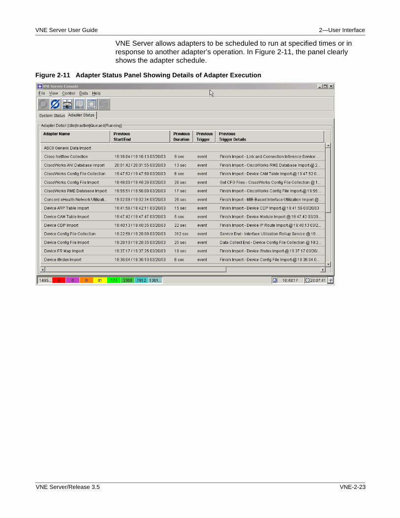
VNE Server User Guide 2—User Interface
VNE Server allows adapters to be scheduled to run at specified times or in response to another adapter’s operation. In Figure 2-11, the panel clearly shows the adapter schedule.
Figure 2-11 Adapter Status Panel Showing Details of Adapter Execution
VNE Server/Release 3.5 VNE-2-23
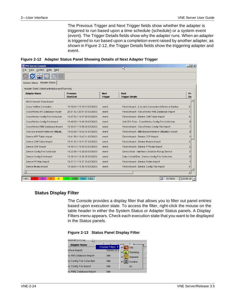
2—User Interface VNE Server User Guide
The Previous Trigger and Next Trigger fields show whether the adapter is triggered to run based upon a time schedule (schedule) or a system event (event). The Trigger Details fields show why the adapter runs. When an adapter is triggered to run based upon a completion event raised by another adapter, as shown in Figure 2-12, the Trigger Details fields show the triggering adapter and event.
Figure 2-12 Adapter Status Panel Showing Details of Next Adapter Trigger
Status Display Filter
The Console provides a display filter that allows you to filter out panel entries based upon execution state. To access the filter, right-click the mouse on the table header in either the System Status or Adapter Status panels. A Display Filters menu appears. Check each execution state that you want to be displayed in the Status panels.
Figure 2-13 Status Panel Display Filter
VNE-2-24 VNE Server/Release 3.5
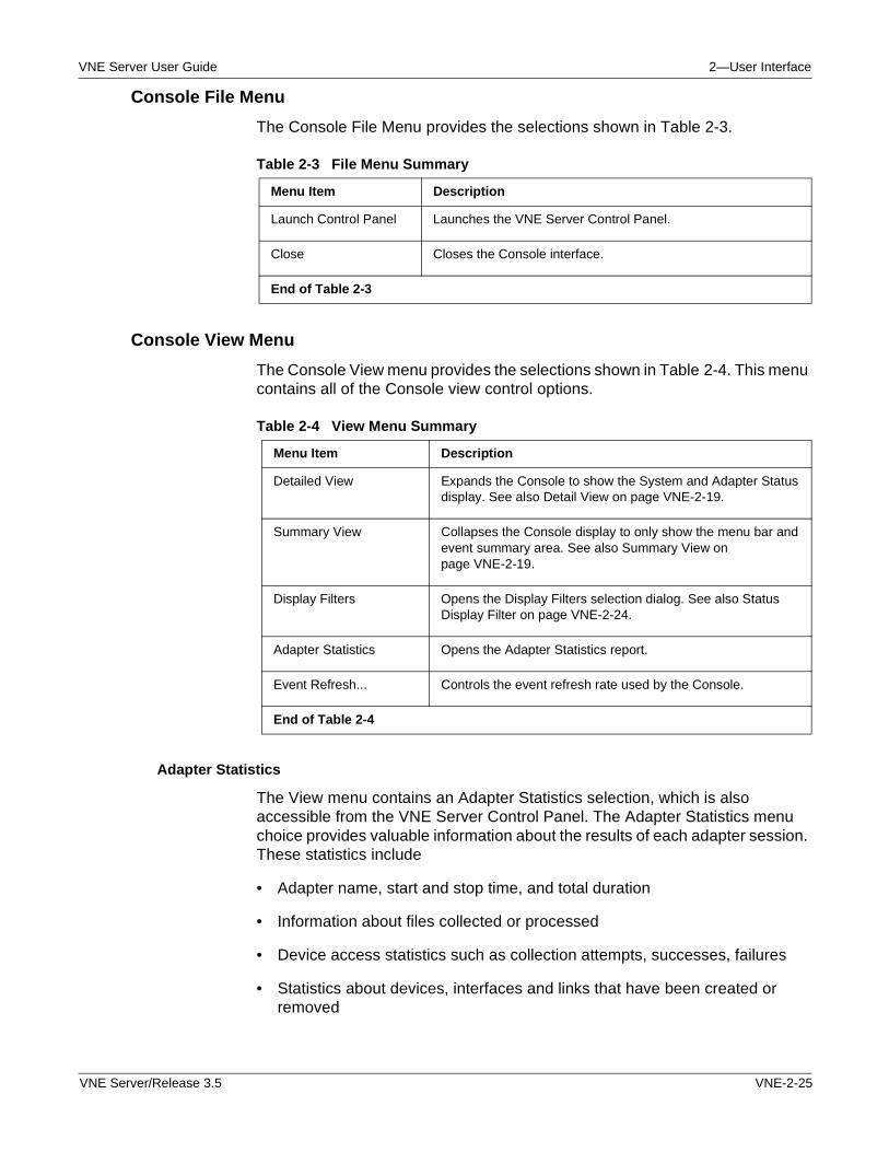
VNE Server User Guide 2—User Interface
Console File Menu
The Console File Menu provides the selections shown in Table 2-3.
Console View Menu
The Console View menu provides the selections shown in Table 2-4. This menu contains all of the Console view control options.
Adapter Statistics
The View menu contains an Adapter Statistics selection, which is also accessible from the VNE Server Control Panel. The Adapter Statistics menu choice provides valuable information about the results of each adapter session. These statistics include
• Adapter name, start and stop time, and total duration
• Information about files collected or processed
• Device access statistics such as collection attempts, successes, failures
• Statistics about devices, interfaces and links that have been created or removed
Table 2-3 File Menu Summary
Menu Item Description
Launch Control Panel Launches the VNE Server Control Panel.
Close Closes the Console interface.
End of Table 2-3
Table 2-4 View Menu Summary
Menu Item Description
Detailed View Expands the Console to show the System and Adapter Status display. See also Detail View on page VNE-2-19.
Summary View Collapses the Console display to only show the menu bar and event summary area. See also Summary View on page VNE-2-19.
Display Filters Opens the Display Filters selection dialog. See also Status Display Filter on page VNE-2-24.
Adapter Statistics Opens the Adapter Statistics report.
Event Refresh... Controls the event refresh rate used by the Console.
End of Table 2-4
VNE Server/Release 3.5 VNE-2-25
2—User Interface VNE Server User Guide
While viewing System Status in the Console is a good way to get information about current system activity, Adapter Statistics is the quickest way to get a good summary of system operation.
• You can see If adapters are running as scheduled.
• You can see if access failures consistently occur.
• You can monitor VNE Server operation.
The Adapter Statistics display is limited to a fixed number of entries that represent the most recent activity. The information displayed in Adapter Statistics is saved in a text file named adapterStats.txt that is located at <temp dir>\adapterStats. This file contains all the Adapter Statistics entries for the current installation of VNE Server, and can be read in any text editor. Starting and stopping services does not affect the contents of the file, so it provides an extended history of adapter operation.
Note—Because the file contents are unaffected by the stopping of services, adapterStats.txt is a good file to include with Technical Support problem reports. For more on filing support calls, see Filing an OPNET Technical Support Case on page VNE-A-34.
VNE-2-26 VNE Server/Release 3.5
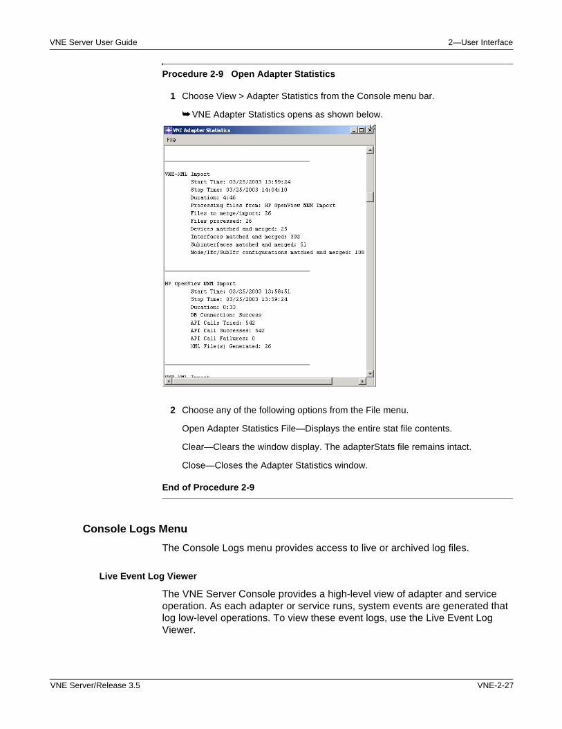
VNE Server User Guide 2—User Interface
Procedure 2-9 Open Adapter Statistics
1 Choose View > Adapter Statistics from the Console menu bar.
➥ VNE Adapter Statistics opens as shown below.
2 Choose any of the following options from the File menu.
Open Adapter Statistics File—Displays the entire stat file contents.
Clear—Clears the window display. The adapterStats file remains intact.
Close—Closes the Adapter Statistics window.
End of Procedure 2-9
Console Logs Menu
The Console Logs menu provides access to live or archived log files.
Live Event Log Viewer
The VNE Server Console provides a high-level view of adapter and service operation. As each adapter or service runs, system events are generated that log low-level operations. To view these event logs, use the Live Event Log Viewer.
VNE Server/Release 3.5 VNE-2-27
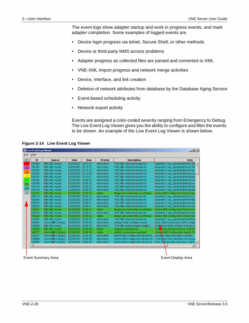
2—User Interface VNE Server User Guide
The event logs show adapter startup and work in progress events, and mark adapter completion. Some examples of logged events are
• Device login progress via telnet, Secure Shell, or other methods
• Device or third-party NMS access problems
• Adapter progress as collected files are parsed and converted to XML
• VNE-XML Import progress and network merge activities
• Device, interface, and link creation
• Deletion of network attributes from database by the Database Aging Service
• Event-based scheduling activity
• Network export activity
Events are assigned a color-coded severity ranging from Emergency to Debug. The Live Event Log Viewer gives you the ability to configure and filter the events to be shown. An example of the Live Event Log Viewer is shown below.
Figure 2-14 Live Event Log Viewer
Event Summary Area Event Display Area
VNE-2-28 VNE Server/Release 3.5
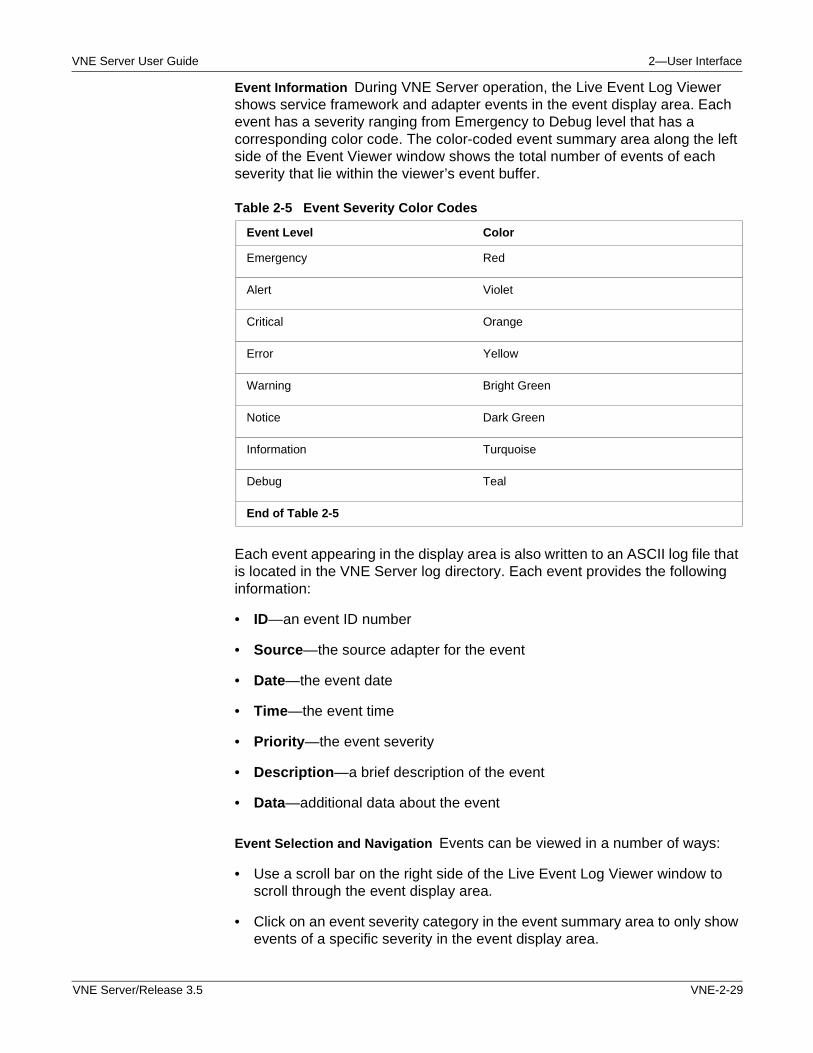
VNE Server User Guide 2—User Interface
Event Information During VNE Server operation, the Live Event Log Viewer shows service framework and adapter events in the event display area. Each event has a severity ranging from Emergency to Debug level that has a corresponding color code. The color-coded event summary area along the left side of the Event Viewer window shows the total number of events of each severity that lie within the viewer’s event buffer.
Each event appearing in the display area is also written to an ASCII log file that is located in the VNE Server log directory. Each event provides the following information:
• ID—an event ID number
• Source—the source adapter for the event
• Date—the event date
• Time—the event time
• Priority—the event severity
• Description—a brief description of the event
• Data—additional data about the event
Event Selection and Navigation Events can be viewed in a number of ways:
• Use a scroll bar on the right side of the Live Event Log Viewer window to scroll through the event display area.
• Click on an event severity category in the event summary area to only show events of a specific severity in the event display area.
Table 2-5 Event Severity Color Codes
Event Level Color
Emergency Red
Alert Violet
Critical Orange
Error Yellow
Warning Bright Green
Notice Dark Green
Information Turquoise
Debug Teal
End of Table 2-5
VNE Server/Release 3.5 VNE-2-29
2—User Interface VNE Server User Guide
• Use the event filter to select events for display based upon time, source and severity.
• Double-click on an event in the display area to open an Event Detail window.
You can display events of a specific severity by clicking the mouse on the severity color in the event summary display. When doing so, only events of the selected severity appear in the display area. This display mode is useful for looking at Error or Critical severity events. Click on the total event count block at the top of the event summary display to restore display of all events in the display area.
The Live Event Log Viewer View menu provides a Filter Events dialog that is used to select events for display based upon source, time, and severity. The event filter is the best way to view all the events from specific adapters. This dialog lets you specify a time interval and event severity for the events that are shown.
Procedure 2-10 Filter Events in Display Area
1 Choose View > Filter Events from the Live Event Log Viewer menu bar.
➥ The Filter Options dialog opens.
2 Use the time selection controls to apply a start time, end time, or both, to the events shown.
3 Use the event source checkboxes to select the events to be shown.
4 Use the event severity checkboxes to select the severity class to be shown.
5 Press the Apply button to apply the event filter to the display area.
Note—Press Cancel to exit without applying any event filter changes.
6 Press OK to exit the Filter Options dialog.
Note—To remove any filtering from the events displayed in the Console, check all adapters and all severities (except Debug). Press OK.
End of Procedure 2-10
VNE-2-30 VNE Server/Release 3.5
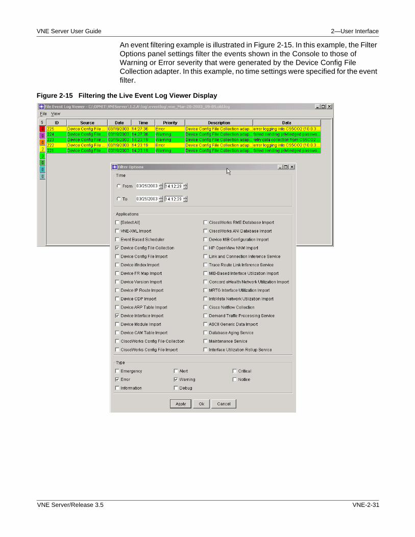
VNE Server User Guide 2—User Interface
An event filtering example is illustrated in Figure 2-15. In this example, the Filter Options panel settings filter the events shown in the Console to those of Warning or Error severity that were generated by the Device Config File Collection adapter. In this example, no time settings were specified for the event filter.
Figure 2-15 Filtering the Live Event Log Viewer Display
VNE Server/Release 3.5 VNE-2-31
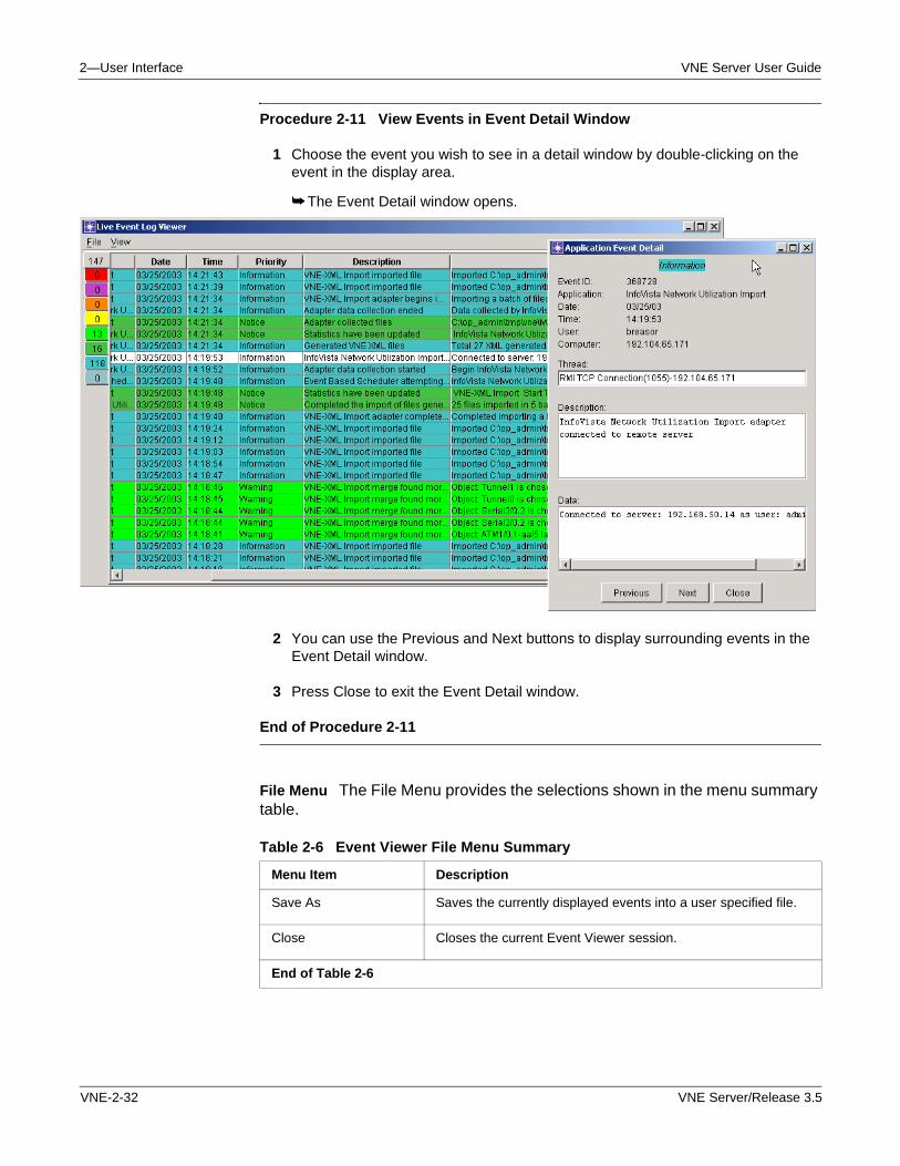
2—User Interface VNE Server User Guide
Procedure 2-11 View Events in Event Detail Window
1 Choose the event you wish to see in a detail window by double-clicking on the event in the display area.
➥ The Event Detail window opens.
2 You can use the Previous and Next buttons to display surrounding events in the Event Detail window.
3 Press Close to exit the Event Detail window.
End of Procedure 2-11
File Menu The File Menu provides the selections shown in the menu summary table.
Table 2-6 Event Viewer File Menu Summary
Menu Item Description
Save As Saves the currently displayed events into a user specified file.
Close Closes the current Event Viewer session.
End of Table 2-6
VNE-2-32 VNE Server/Release 3.5
VNE Server User Guide 2—User Interface
• The Save As selection lets you save events currently shown in the Event Viewer to a log file. This log file can be read by a Event Viewer File Log viewer.
Note—When combined with the event filter, the Save As option is the best way to capture events related to a problem for use by OPNET Technical Support. For more information on filing a case with OPNET Technical Support, see Filing an OPNET Technical Support Case on page VNE-A-34.
• The Close selection closes the Event Viewer window.
View Menu The Event Viewer View menu provides the selections shown in Table 2-7. This menu contains all of the Event Viewer view control options.
Logs Menu The Logs menu lets you access previously saved or archived event log files. The File Event Log Viewer selection prompts you for an event log file, and opens an Event Viewer window that shows the events in the selected log file. A File Log viewer window is only used to view past events.
Table 2-7 View Menu Summary
Menu Item Description
All Events Displays all VNE Server events in the Event Viewer.
Filter Events... Opens a dialog window that allows you to filter the events to be displayed based upon time, event source, and severity.
Newest First Displays the most recent events at the top of the event display.
Oldest First Displays the oldest events at the top of the event display.
Rows... Selects the number of events to be displayed by the Event Viewer.
Columns... Selects the columns to be displayed by the Event Viewer.
Event Refresh... Controls the event refresh rate used by the Event Viewer.
Clear Clears the Event Viewer event display.
Refresh Repaints the current Event Viewer display.
End of Table 2-7
VNE Server/Release 3.5 VNE-2-33
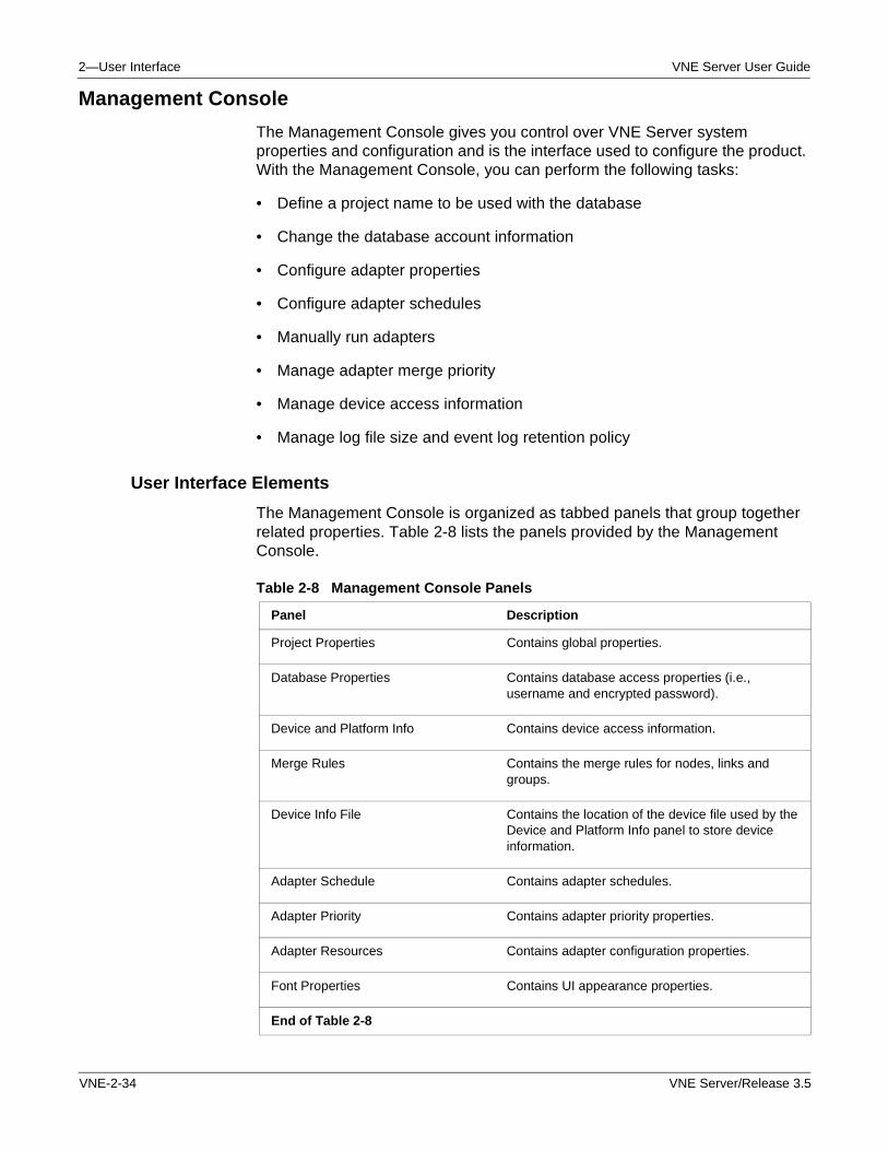
2—User Interface VNE Server User Guide
Management Console
The Management Console gives you control over VNE Server system properties and configuration and is the interface used to configure the product. With the Management Console, you can perform the following tasks:
• Define a project name to be used with the database
• Change the database account information
• Configure adapter properties
• Configure adapter schedules
• Manually run adapters
• Manage adapter merge priority
• Manage device access information
• Manage log file size and event log retention policy
User Interface Elements
The Management Console is organized as tabbed panels that group together related properties. Table 2-8 lists the panels provided by the Management Console.
Table 2-8 Management Console Panels
Panel Description
Project Properties Contains global properties.
Database Properties Contains database access properties (i.e., username and encrypted password).
Device and Platform Info Contains device access information.
Merge Rules Contains the merge rules for nodes, links and groups.
Device Info File Contains the location of the device file used by the Device and Platform Info panel to store device information.
Adapter Schedule Contains adapter schedules.
Adapter Priority Contains adapter priority properties.
Adapter Resources Contains adapter configuration properties.
Font Properties Contains UI appearance properties.
End of Table 2-8
VNE-2-34 VNE Server/Release 3.5
VNE Server User Guide 2—User Interface
Viewing and Editing Properties
The Management Console supports complex and simple properties. Complex properties are composed of other properties, both compound and simple. Simple properties have no children, which means that these properties are leaf nodes in the property tree. The properties in each panel are organized in an expandable, collapsible treeview. When you click on a property, it is highlighted and becomes the focused property. Complex properties are displayed with a file handle.
• To expand a complex property, click on the file handle when it shows a “+”.
• To collapse a complex property, click on the file handle when it shows a “-”.
To change a simple property, click on the property. Depending upon the type of data represented by the property, a pull-down menu, text field, file or directory selector will appear for you to specify changes to the property. After you have edited the property, click on a nearby property to shift focus away from the property just changed. The changes just made to the edited property are now visible.
The properties supported by the Management Console are stored in resource files located in the <install dir>\lib\xml\res directory. When you save changes to properties in the Management Console, these files are updated with the new value of the property. Changes to properties in the Adapter Resource panel are used the next time that the affected adapter runs. Changes to other properties take affect when VNE Server services are stopped and restarted.
The bottom of each Management Console panel has the following control buttons.
• Apply—Saves changes to the resource files.
• OK—Saves changes to the resource files and closes the console.
• Cancel—Closes the console without saving property changes.
VNE Server/Release 3.5 VNE-2-35
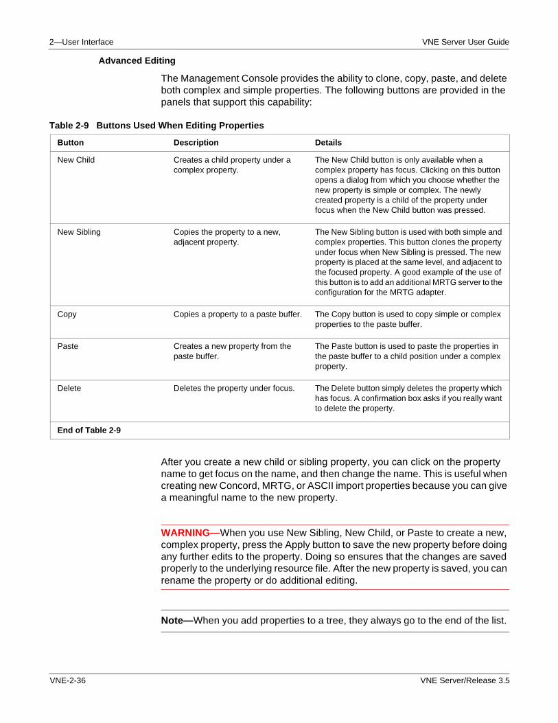
2—User Interface VNE Server User Guide
Advanced Editing
The Management Console provides the ability to clone, copy, paste, and delete both complex and simple properties. The following buttons are provided in the panels that support this capability:
After you create a new child or sibling property, you can click on the property name to get focus on the name, and then change the name. This is useful when creating new Concord, MRTG, or ASCII import properties because you can give a meaningful name to the new property.
WARNING—When you use New Sibling, New Child, or Paste to create a new, complex property, press the Apply button to save the new property before doing any further edits to the property. Doing so ensures that the changes are saved properly to the underlying resource file. After the new property is saved, you can rename the property or do additional editing.
Note—When you add properties to a tree, they always go to the end of the list.
Table 2-9 Buttons Used When Editing Properties
Button Description Details
New Child Creates a child property under a complex property.
The New Child button is only available when a complex property has focus. Clicking on this button opens a dialog from which you choose whether the new property is simple or complex. The newly created property is a child of the property under focus when the New Child button was pressed.
New Sibling Copies the property to a new, adjacent property.
The New Sibling button is used with both simple and complex properties. This button clones the property under focus when New Sibling is pressed. The new property is placed at the same level, and adjacent to the focused property. A good example of the use of this button is to add an additional MRTG server to the configuration for the MRTG adapter.
Copy Copies a property to a paste buffer. The Copy button is used to copy simple or complex properties to the paste buffer.
Paste Creates a new property from the paste buffer.
The Paste button is used to paste the properties in the paste buffer to a child position under a complex property.
Delete Deletes the property under focus. The Delete button simply deletes the property which has focus. A confirmation box asks if you really want to delete the property.
End of Table 2-9
VNE-2-36 VNE Server/Release 3.5
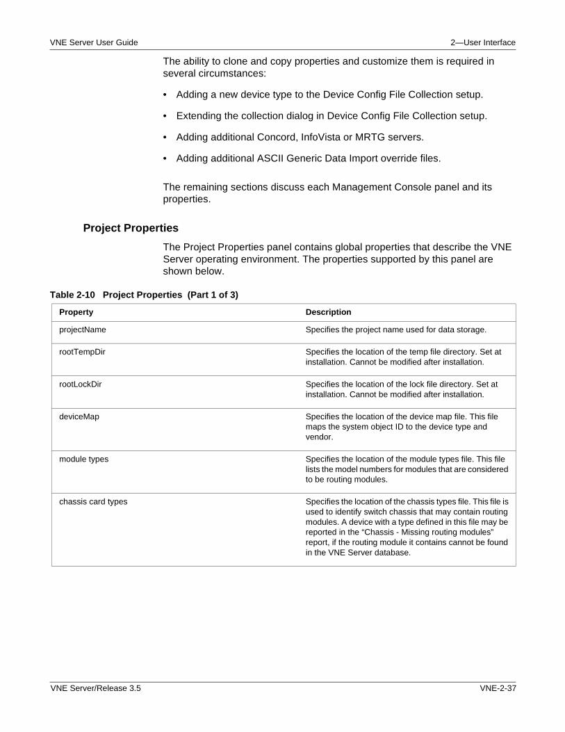
VNE Server User Guide 2—User Interface
The ability to clone and copy properties and customize them is required in several circumstances:
• Adding a new device type to the Device Config File Collection setup.
• Extending the collection dialog in Device Config File Collection setup.
• Adding additional Concord, InfoVista or MRTG servers.
• Adding additional ASCII Generic Data Import override files.
The remaining sections discuss each Management Console panel and its properties.
Project Properties
The Project Properties panel contains global properties that describe the VNE Server operating environment. The properties supported by this panel are shown below.
Table 2-10 Project Properties (Part 1 of 3)
Property Description
projectName Specifies the project name used for data storage.
rootTempDir Specifies the location of the temp file directory. Set at installation. Cannot be modified after installation.
rootLockDir Specifies the location of the lock file directory. Set at installation. Cannot be modified after installation.
deviceMap Specifies the location of the device map file. This file maps the system object ID to the device type and vendor.
module types Specifies the location of the module types file. This file lists the model numbers for modules that are considered to be routing modules.
chassis card types Specifies the location of the chassis types file. This file is used to identify switch chassis that may contain routing modules. A device with a type defined in this file may be reported in the “Chassis - Missing routing modules” report, if the routing module it contains cannot be found in the VNE Server database.
VNE Server/Release 3.5 VNE-2-37
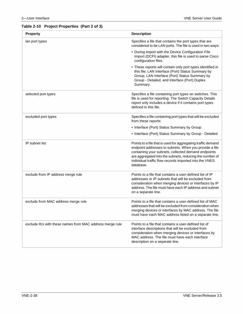
2—User Interface VNE Server User Guide
lan port types Specifies a file that contains the port types that are considered to be LAN ports. The file is used in two ways:
• During import with the Device Configuration FIle Import (DCFI) adapter, this file is used to parse Cisco configuration files.
• These reports will contain only port types identified in this file: LAN Interface (Port) Status Summary by Group, LAN Interface (Port) Status Summary by Group - Detailed, and Interface (Port) Duplex Summary.
selected port types Specifies a file containing port types on switches. This file is used for reporting. The Switch Capacity Details report only includes a device if it contains port types defined in this file.
excluded port types Specifies a file containing port types that will be excluded from these reports:
• Interface (Port) Status Summary by Group
• Interface (Port) Status Summary by Group - Detailed
IP subnet list Points to a file that is used for aggregating traffic demand endpoint addresses to subnets. When you provide a file containing your subnets, collected demand endpoints are aggregated into the subnets, reducing the number of individual traffic flow records imported into the VNES database.
exclude from IP address merge rule Points to a file that contains a user-defined list of IP addresses or IP subnets that will be excluded from consideration when merging devices or interfaces by IP address. The file must have each IP address and subnet on a separate line.
exclude from MAC address merge rule Points to a file that contains a user-defined list of MAC addresses that will be excluded from consideration when merging devices or interfaces by MAC address. The file must have each MAC address listed on a separate line.
exclude ifcs with these names from MAC address merge rule Points to a file that contains a user-defined list of interface descriptions that will be excluded from consideration when merging devices or interfaces by MAC address. The file must have each interface description on a separate line.
Table 2-10 Project Properties (Part 2 of 3)
Property Description
VNE-2-38 VNE Server/Release 3.5
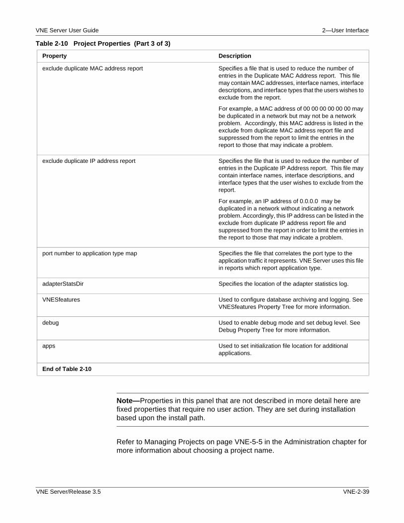
VNE Server User Guide 2—User Interface
Note—Properties in this panel that are not described in more detail here are fixed properties that require no user action. They are set during installation based upon the install path.
Refer to Managing Projects on page VNE-5-5 in the Administration chapter for more information about choosing a project name.
exclude duplicate MAC address report Specifies a file that is used to reduce the number of entries in the Duplicate MAC Address report. This file may contain MAC addresses, interface names, interface descriptions, and interface types that the users wishes to exclude from the report.
For example, a MAC address of 00 00 00 00 00 00 may be duplicated in a network but may not be a network problem. Accordingly, this MAC address is listed in the exclude from duplicate MAC address report file and suppressed from the report to limit the entries in the report to those that may indicate a problem.
exclude duplicate IP address report Specifies the file that is used to reduce the number of entries in the Duplicate IP Address report. This file may contain interface names, interface descriptions, and interface types that the user wishes to exclude from the report.
For example, an IP address of 0.0.0.0 may be duplicated in a network without indicating a network problem. Accordingly, this IP address can be listed in the exclude from duplicate IP address report file and suppressed from the report in order to limit the entries in the report to those that may indicate a problem.
port number to application type map Specifies the file that correlates the port type to the application traffic it represents. VNE Server uses this file in reports which report application type.
adapterStatsDir Specifies the location of the adapter statistics log.
VNESfeatures Used to configure database archiving and logging. See VNESfeatures Property Tree for more information.
debug Used to enable debug mode and set debug level. See Debug Property Tree for more information.
apps Used to set initialization file location for additional applications.
End of Table 2-10
Table 2-10 Project Properties (Part 3 of 3)
Property Description
VNE Server/Release 3.5 VNE-2-39
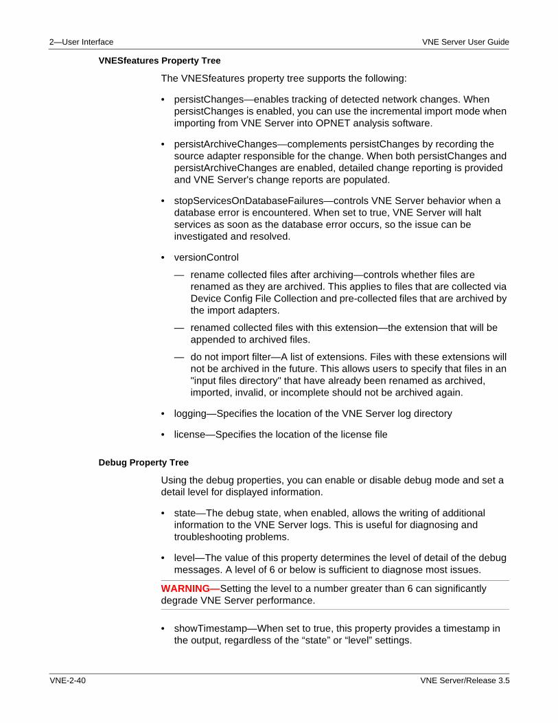
2—User Interface VNE Server User Guide
VNESfeatures Property Tree
The VNESfeatures property tree supports the following:
• persistChanges—enables tracking of detected network changes. When persistChanges is enabled, you can use the incremental import mode when importing from VNE Server into OPNET analysis software.
• persistArchiveChanges—complements persistChanges by recording the source adapter responsible for the change. When both persistChanges and persistArchiveChanges are enabled, detailed change reporting is provided and VNE Server's change reports are populated.
• stopServicesOnDatabaseFailures—controls VNE Server behavior when a database error is encountered. When set to true, VNE Server will halt services as soon as the database error occurs, so the issue can be investigated and resolved.
• versionControl
— rename collected files after archiving—controls whether files are renamed as they are archived. This applies to files that are collected via Device Config File Collection and pre-collected files that are archived by the import adapters.
— renamed collected files with this extension—the extension that will be appended to archived files.
— do not import filter—A list of extensions. Files with these extensions will not be archived in the future. This allows users to specify that files in an "input files directory" that have already been renamed as archived, imported, invalid, or incomplete should not be archived again.
• logging—Specifies the location of the VNE Server log directory
• license—Specifies the location of the license file
Debug Property Tree
Using the debug properties, you can enable or disable debug mode and set a detail level for displayed information.
• state—The debug state, when enabled, allows the writing of additional information to the VNE Server logs. This is useful for diagnosing and troubleshooting problems.
• level—The value of this property determines the level of detail of the debug messages. A level of 6 or below is sufficient to diagnose most issues.
WARNING—Setting the level to a number greater than 6 can significantly degrade VNE Server performance.
• showTimestamp—When set to true, this property provides a timestamp in the output, regardless of the “state” or “level” settings.
VNE-2-40 VNE Server/Release 3.5
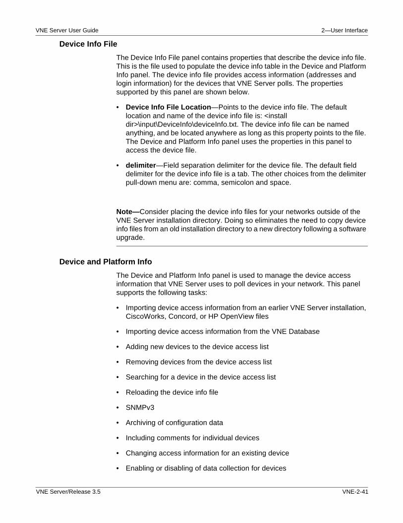
VNE Server User Guide 2—User Interface
Device Info File
The Device Info File panel contains properties that describe the device info file. This is the file used to populate the device info table in the Device and Platform Info panel. The device info file provides access information (addresses and login information) for the devices that VNE Server polls. The properties supported by this panel are shown below.
• Device Info File Location—Points to the device info file. The default location and name of the device info file is: <install dir>\input\DeviceInfo\deviceInfo.txt. The device info file can be named anything, and be located anywhere as long as this property points to the file. The Device and Platform Info panel uses the properties in this panel to access the device file.
• delimiter—Field separation delimiter for the device file. The default field delimiter for the device info file is a tab. The other choices from the delimiter pull-down menu are: comma, semicolon and space.
Note—Consider placing the device info files for your networks outside of the VNE Server installation directory. Doing so eliminates the need to copy device info files from an old installation directory to a new directory following a software upgrade.
Device and Platform Info
The Device and Platform Info panel is used to manage the device access information that VNE Server uses to poll devices in your network. This panel supports the following tasks:
• Importing device access information from an earlier VNE Server installation, CiscoWorks, Concord, or HP OpenView files
• Importing device access information from the VNE Database
• Adding new devices to the device access list
• Removing devices from the device access list
• Searching for a device in the device access list
• Reloading the device info file
• SNMPv3
• Archiving of configuration data
• Including comments for individual devices
• Changing access information for an existing device
• Enabling or disabling of data collection for devices
VNE Server/Release 3.5 VNE-2-41
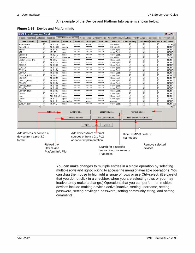
2—User Interface VNE Server User Guide
An example of the Device and Platform Info panel is shown below:
Figure 2-16 Device and Platform Info
You can make changes to multiple entries in a single operation by selecting multiple rows and right-clicking to access the menu of available operations. You can drag the mouse to highlight a range of rows or use Ctrl+select. (Be careful that you do not click in a checkbox when you are selecting rows or you may inadvertently make a change.) Operations that you can perform on multiple devices include making devices active/inactive, setting username, setting password, setting privileged password, setting community string, and setting comments.
Search for a specific device using hostname or IP address
Add devices or convert a device from a pre-3.0 format
Add devices from external sources or from a 2.1 PL2 or earlier implementation
Hide SNMPv3 fields, if not needed
Remove selected devices
Reload the Device and Platform Info File
VNE-2-42 VNE Server/Release 3.5
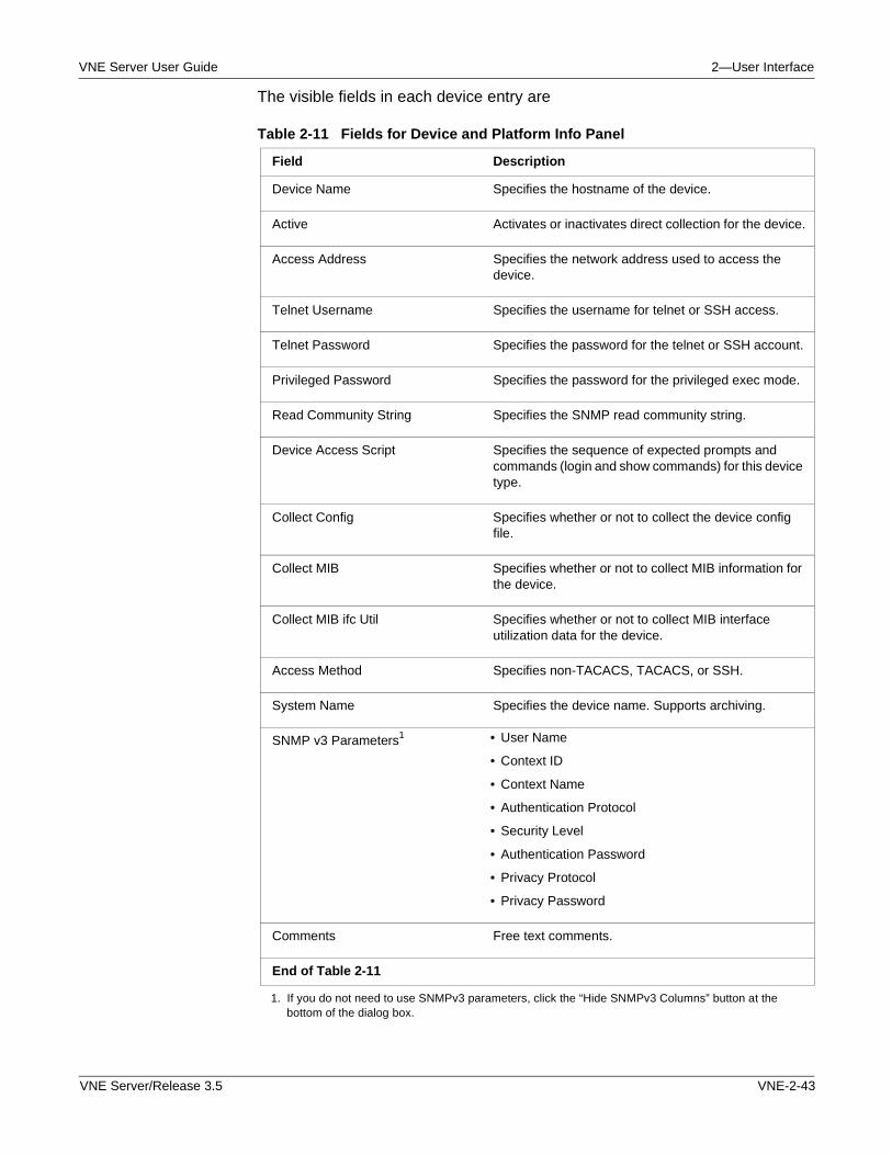
VNE Server User Guide 2—User Interface
The visible fields in each device entry are
Table 2-11 Fields for Device and Platform Info Panel
Field Description
Device Name Specifies the hostname of the device.
Active Activates or inactivates direct collection for the device.
Access Address Specifies the network address used to access the device.
Telnet Username Specifies the username for telnet or SSH access.
Telnet Password Specifies the password for the telnet or SSH account.
Privileged Password Specifies the password for the privileged exec mode.
Read Community String Specifies the SNMP read community string.
Device Access Script Specifies the sequence of expected prompts and commands (login and show commands) for this device type.
Collect Config Specifies whether or not to collect the device config file.
Collect MIB Specifies whether or not to collect MIB information for the device.
Collect MIB ifc Util Specifies whether or not to collect MIB interface utilization data for the device.
Access Method Specifies non-TACACS, TACACS, or SSH.
System Name Specifies the device name. Supports archiving.
SNMP v3 Parameters1
1. If you do not need to use SNMPv3 parameters, click the “Hide SNMPv3 Columns” button at the bottom of the dialog box.
• User Name
• Context ID
• Context Name
• Authentication Protocol
• Security Level
• Authentication Password
• Privacy Protocol
• Privacy Password
Comments Free text comments.
End of Table 2-11
VNE Server/Release 3.5 VNE-2-43
2—User Interface VNE Server User Guide
The password and community string fields are encrypted both at the file level and in the Device and Platform Info display.
Note—The device type and vendor subtypes defined for the Device Config File Collection adapter in the Adapter Resources panel are used to populate the Device Access Script field.
Manually Creating a Device Info File
The device info file can be constructed off-line in an editor such as Wordpad or in a spreadsheet.
Note—To generate a starter file that with header information and column headers, open the Management Console, Device and Platform Info tab and add a device, then press the Apply button. The device info file is generated to the location and filename specified in the Device Info File tab of the Management Console.
Offline methods work best for creating an initial device information file for a large network. This is especially true if you already have files that list device names and their access addresses.
Note—For more information about the fields in the Device Info File, refer to Format of the Device Info File on page VNE-C-1.
You can use a spreadsheet to create the device file. To do so, perform the following steps.
Procedure 2-12 Manually Creating a Device Info File
1 Import your existing device name and address file into a spreadsheet.
2 Use the spreadsheet’s editing tools to fill in missing data.
3 Copy the file to the device file location configured in the Device Info File panel in the Management Console.
4 Open the Device and Platform Info panel to view the contents of the device file.
Note—If the device data does not display as expected, verify that the field order and delimiter is correct.
5 Correct any problems found, such as missing addresses or incorrect device names.
End of Procedure 2-12
VNE-2-44 VNE Server/Release 3.5
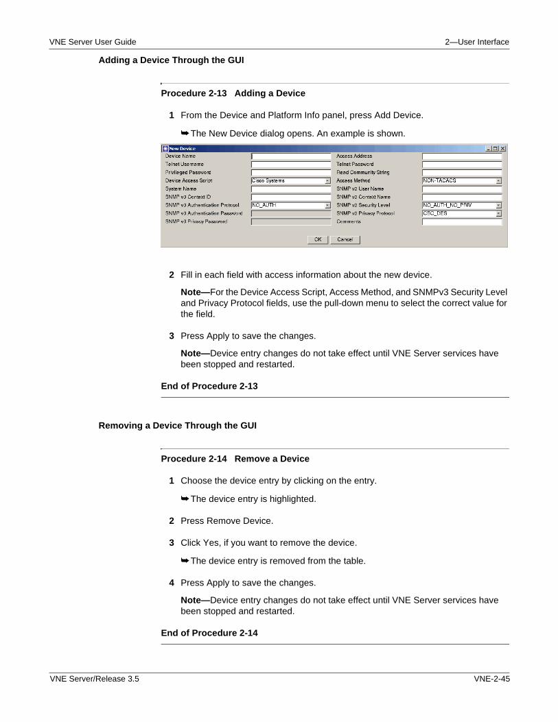
VNE Server User Guide 2—User Interface
Adding a Device Through the GUI
Procedure 2-13 Adding a Device
1 From the Device and Platform Info panel, press Add Device.
➥ The New Device dialog opens. An example is shown.
2 Fill in each field with access information about the new device.
Note—For the Device Access Script, Access Method, and SNMPv3 Security Level and Privacy Protocol fields, use the pull-down menu to select the correct value for the field.
3 Press Apply to save the changes.
Note—Device entry changes do not take effect until VNE Server services have been stopped and restarted.
End of Procedure 2-13
Removing a Device Through the GUI
Procedure 2-14 Remove a Device
1 Choose the device entry by clicking on the entry.
➥ The device entry is highlighted.
2 Press Remove Device.
3 Click Yes, if you want to remove the device.
➥ The device entry is removed from the table.
4 Press Apply to save the changes.
Note—Device entry changes do not take effect until VNE Server services have been stopped and restarted.
End of Procedure 2-14
VNE Server/Release 3.5 VNE-2-45
2—User Interface VNE Server User Guide
Using a CiscoWorks Inventory File to Create a Device Info File
Procedure 2-15 Adding Devices from CiscoWorks Inventory File
Note—To obtain a CiscoWorks inventory file for use in this procedure, refer to Collecting a CiscoWorks Inventory File on page VNE-5-40 in the Administration chapter.
1 Press Add Devices from...
➥ A menu with a list of import sources opens.
2 Choose CiscoWorks Inventory File.
➥ A standard file selection dialog opens.
3 Use the file selection dialog to select the CiscoWorks inventory file to be imported, and press Select.
➥ New devices appear in the device list that have been created from the CiscoWorks inventory file.
Note—Devices created from CiscoWorks inventory file are missing information from some fields. Fill in the empty fields before you save the changes.
4 Press Apply to save the changes.
Note—Device entry changes do not take effect until VNE Server services have been stopped and restarted.
End of Procedure 2-15
Using a Concord dci File to Create a Device Info File
Procedure 2-16 Create a Device Info File from a Concord dci File
1 Press Add Devices from...
➥ A menu with a list of import sources opens.
2 Choose Concord Config File.
➥ A standard file selection dialog opens.
3 Use the file selection dialog to select the Concord dci file to be imported. Press Select.
➥ New devices appear in the device list that have been created from the Concord dci file.
Note—Devices created from Concord dci files are missing information from the following fields: telnet username, Device Type, Access, and Access Method. Fill in these fields before you save the changes.
VNE-2-46 VNE Server/Release 3.5
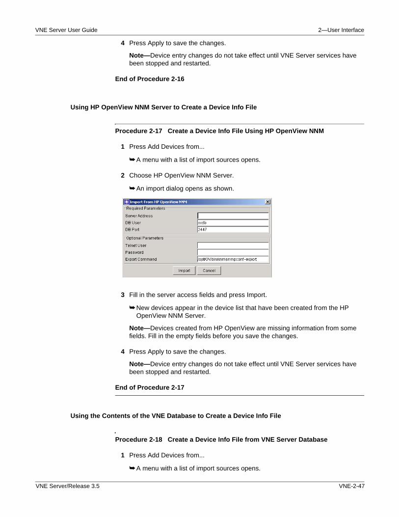
VNE Server User Guide 2—User Interface
4 Press Apply to save the changes.
Note—Device entry changes do not take effect until VNE Server services have been stopped and restarted.
End of Procedure 2-16
Using HP OpenView NNM Server to Create a Device Info File
Procedure 2-17 Create a Device Info File Using HP OpenView NNM
1 Press Add Devices from...
➥ A menu with a list of import sources opens.
2 Choose HP OpenView NNM Server.
➥ An import dialog opens as shown.
3 Fill in the server access fields and press Import.
➥ New devices appear in the device list that have been created from the HP OpenView NNM Server.
Note—Devices created from HP OpenView are missing information from some fields. Fill in the empty fields before you save the changes.
4 Press Apply to save the changes.
Note—Device entry changes do not take effect until VNE Server services have been stopped and restarted.
End of Procedure 2-17
Using the Contents of the VNE Database to Create a Device Info File
Procedure 2-18 Create a Device Info File from VNE Server Database
1 Press Add Devices from...
➥ A menu with a list of import sources opens.
VNE Server/Release 3.5 VNE-2-47
2—User Interface VNE Server User Guide
2 Choose VNE Database.
➥ Devices in the database are added to the device list in the Device and Platform Info panel. Devices are inactive, by default.
3 Click on the checkbox in the Active field to enable collection from a device.
4 Check each field in the entry and correct or add data as needed to complete the entry.
Note—Cisco devices are populated as using a Device Access Script named Cisco Systems. For these devices, change the Device Access Script to Cisco.
Note—Device entry changes do not take effect until VNE Server services have been stopped and restarted.
End of Procedure 2-18
Reload the Device Info File
A button is provided on the Device and Platform Info tab that lets you reload the Device Info file without stopping and restarting VNE Server. Press the button to read in a new file or changes to an existing file.
Using the Active Checkbox to Control Device Data Collection
The Active field in the Device and Platform Info table controls whether data collection occurs for a given device. When checked, adapters such as Device Config File Collection and Device MIB Configuration Import attempt to collect data from the device. When unchecked, the device is skipped during data collection.
The main use of the Active field is to change collection status of a device for troubleshooting purposes. This can be done on a device by device basis, or for each device in the table.
• To enable or disable collection for all devices in the table, right-click in the Active field heading to open a menu. The menu choices are: all active and all inactive. Choose one to change the state of all devices to the desired state.
• To work with a small number of devices, disable all using the Active menu, and click in the Active check boxes to enable the devices you want to test. When done, use the Active menu to enable all devices for operational data collection.
New abilities for greater control over data collection were introduced in 3.0. In addition to the global Active flag, there is a flag for Collect Config, Collect MIB, and Collect MIB Ifc Util. These additional flags can be set for a specific device to determine whether data collection should be attempted by the supporting adapter. These controls can be employed in the following way. There may be a
VNE-2-48 VNE Server/Release 3.5
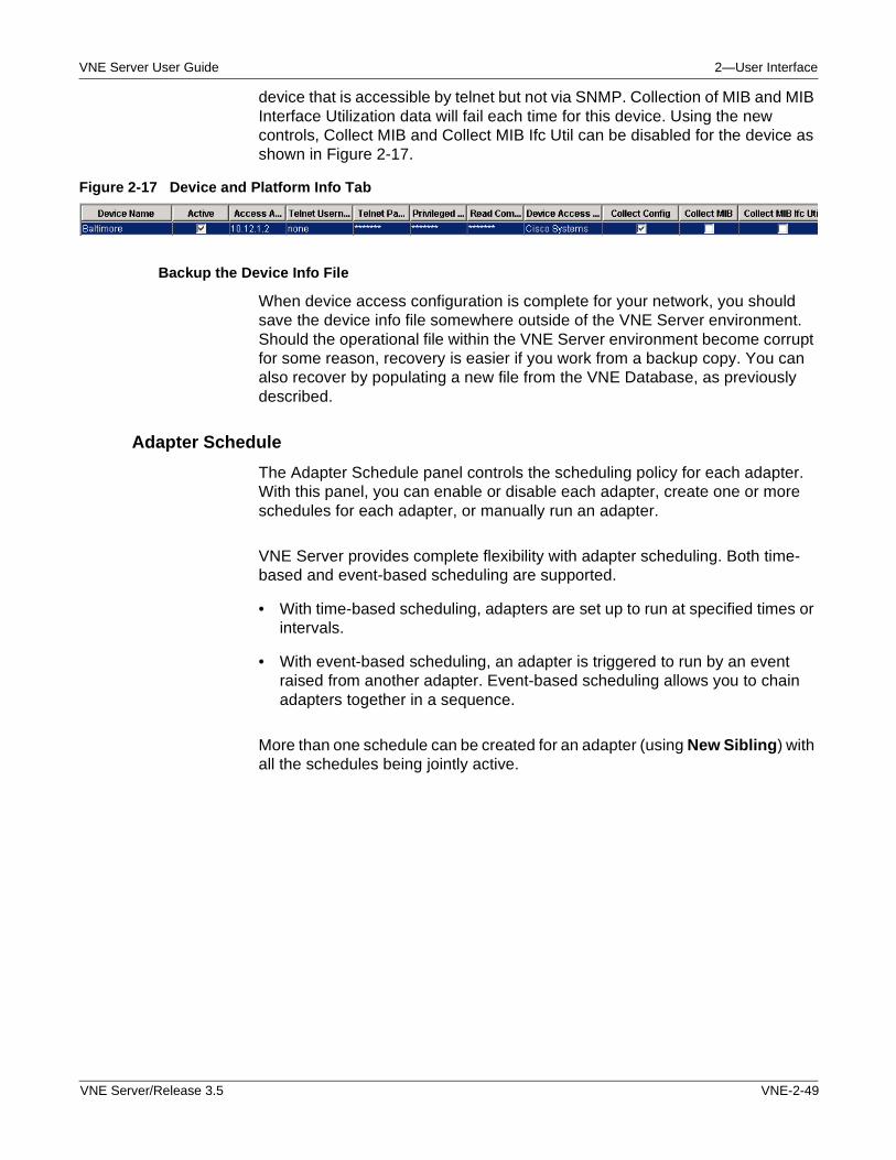
VNE Server User Guide 2—User Interface
device that is accessible by telnet but not via SNMP. Collection of MIB and MIB Interface Utilization data will fail each time for this device. Using the new controls, Collect MIB and Collect MIB Ifc Util can be disabled for the device as shown in Figure 2-17.
Figure 2-17 Device and Platform Info Tab
Backup the Device Info File
When device access configuration is complete for your network, you should save the device info file somewhere outside of the VNE Server environment. Should the operational file within the VNE Server environment become corrupt for some reason, recovery is easier if you work from a backup copy. You can also recover by populating a new file from the VNE Database, as previously described.
Adapter Schedule
The Adapter Schedule panel controls the scheduling policy for each adapter. With this panel, you can enable or disable each adapter, create one or more schedules for each adapter, or manually run an adapter.
VNE Server provides complete flexibility with adapter scheduling. Both time- based and event-based scheduling are supported.
• With time-based scheduling, adapters are set up to run at specified times or intervals.
• With event-based scheduling, an adapter is triggered to run by an event raised from another adapter. Event-based scheduling allows you to chain adapters together in a sequence.
More than one schedule can be created for an adapter (using New Sibling) with all the schedules being jointly active.
VNE Server/Release 3.5 VNE-2-49
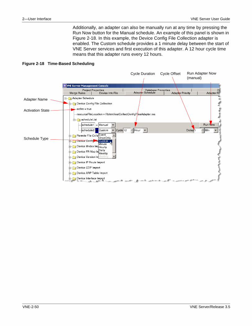
2—User Interface VNE Server User Guide
Additionally, an adapter can also be manually run at any time by pressing the Run Now button for the Manual schedule. An example of this panel is shown in Figure 2-18. In this example, the Device Config File Collection adapter is enabled. The Custom schedule provides a 1 minute delay between the start of VNE Server services and first execution of this adapter. A 12 hour cycle time means that this adapter runs every 12 hours.
Figure 2-18 Time-Based Scheduling
Adapter Name
Activation State
Schedule Type
Run Adapter Now (manual)
Cycle OffsetCycle Duration
VNE-2-50 VNE Server/Release 3.5
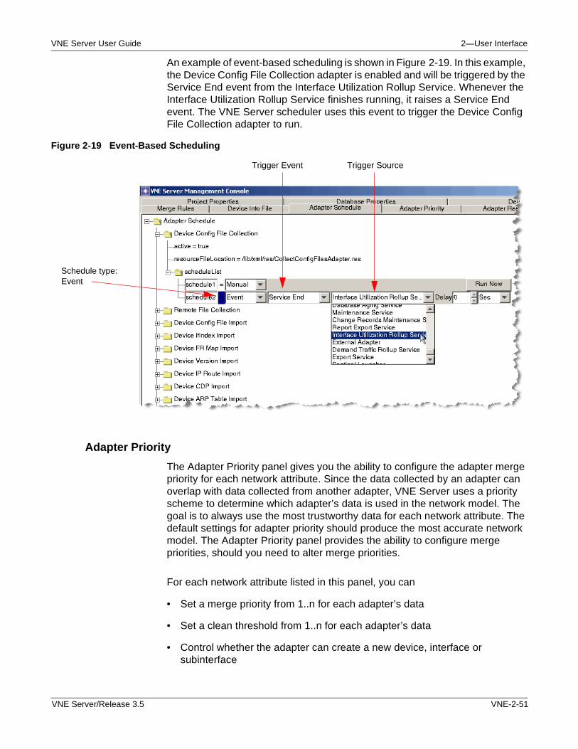
VNE Server User Guide 2—User Interface
An example of event-based scheduling is shown in Figure 2-19. In this example, the Device Config File Collection adapter is enabled and will be triggered by the Service End event from the Interface Utilization Rollup Service. Whenever the Interface Utilization Rollup Service finishes running, it raises a Service End event. The VNE Server scheduler uses this event to trigger the Device Config File Collection adapter to run.
Figure 2-19 Event-Based Scheduling
Adapter Priority
The Adapter Priority panel gives you the ability to configure the adapter merge priority for each network attribute. Since the data collected by an adapter can overlap with data collected from another adapter, VNE Server uses a priority scheme to determine which adapter’s data is used in the network model. The goal is to always use the most trustworthy data for each network attribute. The default settings for adapter priority should produce the most accurate network model. The Adapter Priority panel provides the ability to configure merge priorities, should you need to alter merge priorities.
For each network attribute listed in this panel, you can
• Set a merge priority from 1..n for each adapter’s data
• Set a clean threshold from 1..n for each adapter’s data
• Control whether the adapter can create a new device, interface or subinterface
Schedule type: Event
Trigger Event Trigger Source
VNE Server/Release 3.5 VNE-2-51
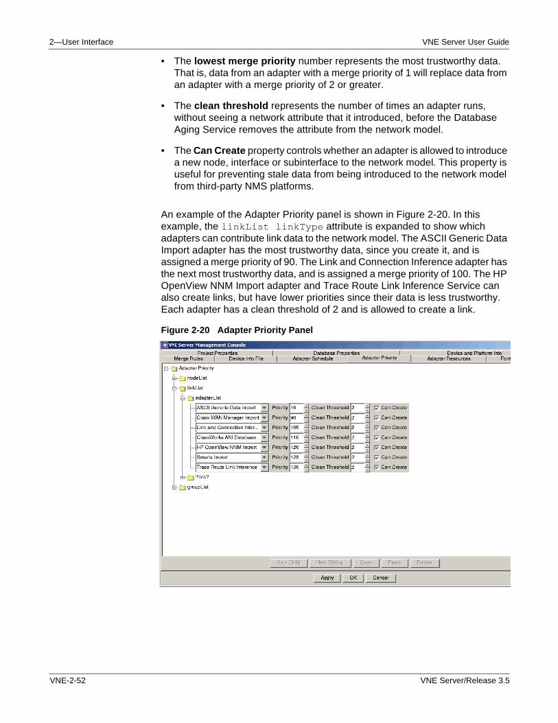
2—User Interface VNE Server User Guide
• The lowest merge priority number represents the most trustworthy data. That is, data from an adapter with a merge priority of 1 will replace data from an adapter with a merge priority of 2 or greater.
• The clean threshold represents the number of times an adapter runs, without seeing a network attribute that it introduced, before the Database Aging Service removes the attribute from the network model.
• The Can Create property controls whether an adapter is allowed to introduce a new node, interface or subinterface to the network model. This property is useful for preventing stale data from being introduced to the network model from third-party NMS platforms.
An example of the Adapter Priority panel is shown in Figure 2-20. In this example, the linkList linkType attribute is expanded to show which adapters can contribute link data to the network model. The ASCII Generic Data Import adapter has the most trustworthy data, since you create it, and is assigned a merge priority of 90. The Link and Connection Inference adapter has the next most trustworthy data, and is assigned a merge priority of 100. The HP OpenView NNM Import adapter and Trace Route Link Inference Service can also create links, but have lower priorities since their data is less trustworthy. Each adapter has a clean threshold of 2 and is allowed to create a link.
Figure 2-20 Adapter Priority Panel
VNE-2-52 VNE Server/Release 3.5
VNE Server User Guide 2—User Interface
Adapter Resources
The Adapter Resources panel contains the configuration properties for each adapter and service offered by VNE Server. Each time an adapter runs, it initializes itself from the properties contained in this panel. Some examples of adapter properties are
• Timeout and retry values governing device access by the adapter
• Vendor specific configuration collection commands
• Platform and database access properties for third-party NMS platforms
• The location of working directories or control files
The Adapter Resources panel uses the same expandable property treeview that is used throughout the Management Console. Each adapter has its own property tree. For more information about each adapter and its configurable properties, refer to the Adapters and Services chapter.
Font Properties
The Font Properties panel gives you control over the visual appearance of menu labels, menu items, table headers and tooltips. In this panel, you can change the font name, style and size for each property. The changes effect menu appearance in the Console, Network Browser and Report Manager. Property changes take effect after you exit and re-enter VNE Server.
Merge Rules
The Merge Rules panel gives you the ability to configure the rules used to match and merge nodes, interfaces, links and groups into the network model. Each category supports multiple rules. Each rule can be set active or inactive and has a weight property that determines which data merge rule takes precedence.
VNE Server/Release 3.5 VNE-2-53
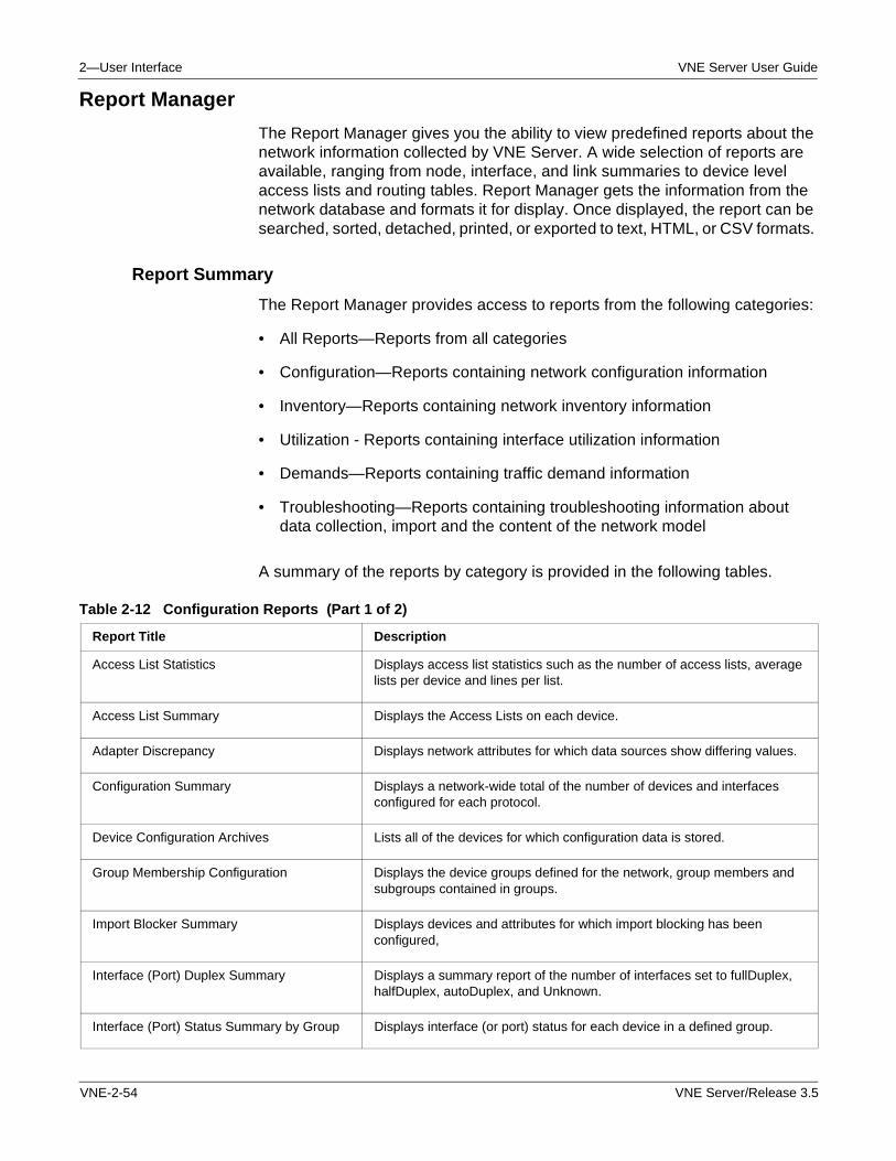
2—User Interface VNE Server User Guide
Report Manager
The Report Manager gives you the ability to view predefined reports about the network information collected by VNE Server. A wide selection of reports are available, ranging from node, interface, and link summaries to device level access lists and routing tables. Report Manager gets the information from the network database and formats it for display. Once displayed, the report can be searched, sorted, detached, printed, or exported to text, HTML, or CSV formats.
Report Summary
The Report Manager provides access to reports from the following categories:
• All Reports—Reports from all categories
• Configuration—Reports containing network configuration information
• Inventory—Reports containing network inventory information
• Utilization - Reports containing interface utilization information
• Demands—Reports containing traffic demand information
• Troubleshooting—Reports containing troubleshooting information about data collection, import and the content of the network model
A summary of the reports by category is provided in the following tables.
Table 2-12 Configuration Reports (Part 1 of 2)
Report Title Description
Access List Statistics Displays access list statistics such as the number of access lists, average lists per device and lines per list.
Access List Summary Displays the Access Lists on each device.
Adapter Discrepancy Displays network attributes for which data sources show differing values.
Configuration Summary Displays a network-wide total of the number of devices and interfaces configured for each protocol.
Device Configuration Archives Lists all of the devices for which configuration data is stored.
Group Membership Configuration Displays the device groups defined for the network, group members and subgroups contained in groups.
Import Blocker Summary Displays devices and attributes for which import blocking has been configured,
Interface (Port) Duplex Summary Displays a summary report of the number of interfaces set to fullDuplex, halfDuplex, autoDuplex, and Unknown.
Interface (Port) Status Summary by Group Displays interface (or port) status for each device in a defined group.
VNE-2-54 VNE Server/Release 3.5
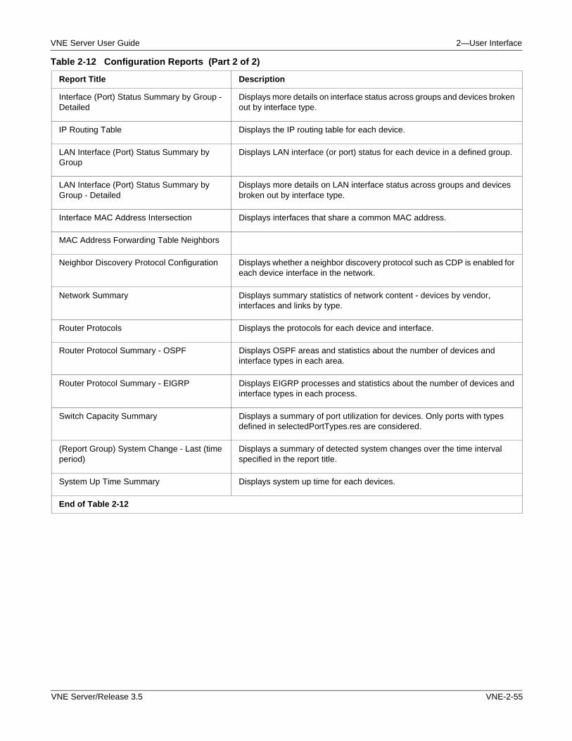
VNE Server User Guide 2—User Interface
Interface (Port) Status Summary by Group - Detailed
Displays more details on interface status across groups and devices broken out by interface type.
IP Routing Table Displays the IP routing table for each device.
LAN Interface (Port) Status Summary by Group
Displays LAN interface (or port) status for each device in a defined group.
LAN Interface (Port) Status Summary by Group - Detailed
Displays more details on LAN interface status across groups and devices broken out by interface type.
Interface MAC Address Intersection Displays interfaces that share a common MAC address.
MAC Address Forwarding Table Neighbors
Neighbor Discovery Protocol Configuration Displays whether a neighbor discovery protocol such as CDP is enabled for each device interface in the network.
Network Summary Displays summary statistics of network content - devices by vendor, interfaces and links by type.
Router Protocols Displays the protocols for each device and interface.
Router Protocol Summary - OSPF Displays OSPF areas and statistics about the number of devices and interface types in each area.
Router Protocol Summary - EIGRP Displays EIGRP processes and statistics about the number of devices and interface types in each process.
Switch Capacity Summary Displays a summary of port utilization for devices. Only ports with types defined in selectedPortTypes.res are considered.
(Report Group) System Change - Last (time period)
Displays a summary of detected system changes over the time interval specified in the report title.
System Up Time Summary Displays system up time for each devices.
End of Table 2-12
Table 2-12 Configuration Reports (Part 2 of 2)
Report Title Description
VNE Server/Release 3.5 VNE-2-55
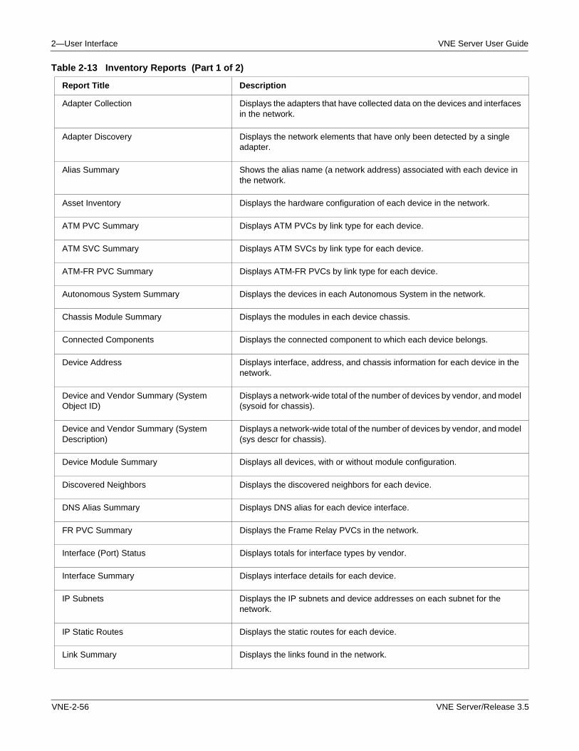
2—User Interface VNE Server User Guide
Table 2-13 Inventory Reports (Part 1 of 2)
Report Title Description
Adapter Collection Displays the adapters that have collected data on the devices and interfaces in the network.
Adapter Discovery Displays the network elements that have only been detected by a single adapter.
Alias Summary Shows the alias name (a network address) associated with each device in the network.
Asset Inventory Displays the hardware configuration of each device in the network.
ATM PVC Summary Displays ATM PVCs by link type for each device.
ATM SVC Summary Displays ATM SVCs by link type for each device.
ATM-FR PVC Summary Displays ATM-FR PVCs by link type for each device.
Autonomous System Summary Displays the devices in each Autonomous System in the network.
Chassis Module Summary Displays the modules in each device chassis.
Connected Components Displays the connected component to which each device belongs.
Device Address Displays interface, address, and chassis information for each device in the network.
Device and Vendor Summary (System Object ID)
Displays a network-wide total of the number of devices by vendor, and model (sysoid for chassis).
Device and Vendor Summary (System Description)
Displays a network-wide total of the number of devices by vendor, and model (sys descr for chassis).
Device Module Summary Displays all devices, with or without module configuration.
Discovered Neighbors Displays the discovered neighbors for each device.
DNS Alias Summary Displays DNS alias for each device interface.
FR PVC Summary Displays the Frame Relay PVCs in the network.
Interface (Port) Status Displays totals for interface types by vendor.
Interface Summary Displays interface details for each device.
IP Subnets Displays the IP subnets and device addresses on each subnet for the network.
IP Static Routes Displays the static routes for each device.
Link Summary Displays the links found in the network.
VNE-2-56 VNE Server/Release 3.5
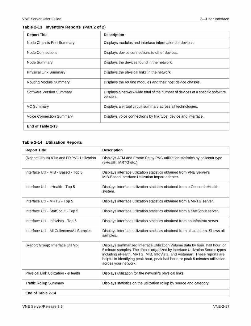
VNE Server User Guide 2—User Interface
Node Chassis Port Summary Displays modules and interface information for devices.
Node Connections Displays device connections to other devices.
Node Summary Displays the devices found in the network.
Physical Link Summary Displays the physical links in the network.
Routing Module Summary Displays the routing modules and their host device chassis,
Software Version Summary Displays a network-wide total of the number of devices at a specific software version.
VC Summary Displays a virtual circuit summary across all technologies.
Voice Connection Summary Displays voice connections by link type, device and interface.
End of Table 2-13
Table 2-13 Inventory Reports (Part 2 of 2)
Report Title Description
Table 2-14 Utilization Reports
Report Title Description
(Report Group) ATM and FR PVC Utilization Displays ATM and Frame Relay PVC utilization statistics by collector type (eHealth, MRTG etc.)
Interface Util - MIB - Based - Top 5 Displays interface utilization statistics obtained from VNE Server’s MIB-Based Interface Utilization Import adapter.
Interface Util - eHealth - Top 5 Displays interface utilization statistics obtained from a Concord eHealth system.
Interface Util - MRTG - Top 5 Displays interface utilization statistics obtained from a MRTG server.
Interface Util - StatScout - Top 5 Displays interface utilization statistics obtained from a StatScout server.
Interface Util - InfoVista - Top 5 Displays interface utilization statistics obtained from an InfoVista server.
Interface Util - All Collectors/All Samples Displays interface utilization statistics obtained from all adapters. Shows all samples.
(Report Group) Interface Util Vol Displays summarized Interface Utilization Volume data by hour, half hour, or 5 minute samples. The data is organized by Interface Utilization Source types including eHealth, MRTG, MIB, InfoVista, and Vistamart. These reports are helpful in identifying peak hour, peak half hour, or peak 5 minutes utilization across your network.
Physical Link Utilization - eHealth Displays utilization for the network’s physical links.
Traffic Rollup Summary Displays statistics on the utilization rollup by source and category.
End of Table 2-14
VNE Server/Release 3.5 VNE-2-57
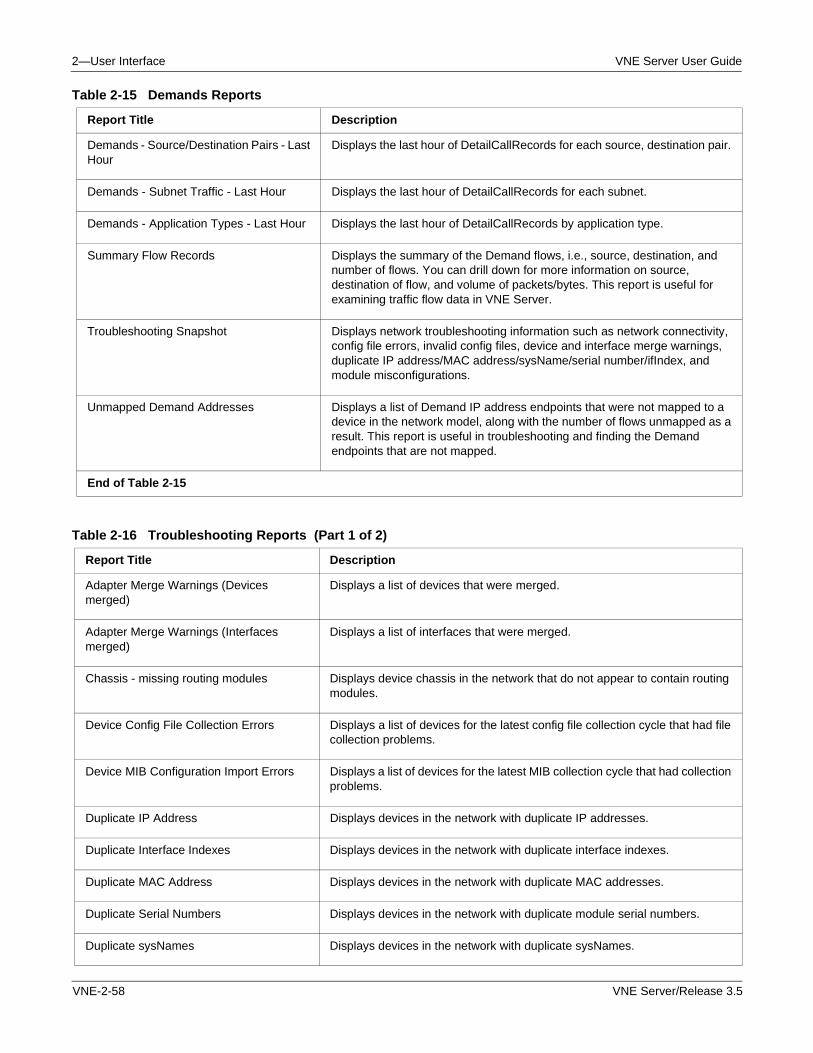
2—User Interface VNE Server User Guide
Table 2-15 Demands Reports
Report Title Description
Demands - Source/Destination Pairs - Last Hour
Displays the last hour of DetailCallRecords for each source, destination pair.
Demands - Subnet Traffic - Last Hour Displays the last hour of DetailCallRecords for each subnet.
Demands - Application Types - Last Hour Displays the last hour of DetailCallRecords by application type.
Summary Flow Records Displays the summary of the Demand flows, i.e., source, destination, and number of flows. You can drill down for more information on source, destination of flow, and volume of packets/bytes. This report is useful for examining traffic flow data in VNE Server.
Troubleshooting Snapshot Displays network troubleshooting information such as network connectivity, config file errors, invalid config files, device and interface merge warnings, duplicate IP address/MAC address/sysName/serial number/ifIndex, and module misconfigurations.
Unmapped Demand Addresses Displays a list of Demand IP address endpoints that were not mapped to a device in the network model, along with the number of flows unmapped as a result. This report is useful in troubleshooting and finding the Demand endpoints that are not mapped.
End of Table 2-15
Table 2-16 Troubleshooting Reports (Part 1 of 2)
Report Title Description
Adapter Merge Warnings (Devices merged)
Displays a list of devices that were merged.
Adapter Merge Warnings (Interfaces merged)
Displays a list of interfaces that were merged.
Chassis - missing routing modules Displays device chassis in the network that do not appear to contain routing modules.
Device Config File Collection Errors Displays a list of devices for the latest config file collection cycle that had file collection problems.
Device MIB Configuration Import Errors Displays a list of devices for the latest MIB collection cycle that had collection problems.
Duplicate IP Address Displays devices in the network with duplicate IP addresses.
Duplicate Interface Indexes Displays devices in the network with duplicate interface indexes.
Duplicate MAC Address Displays devices in the network with duplicate MAC addresses.
Duplicate Serial Numbers Displays devices in the network with duplicate module serial numbers.
Duplicate sysNames Displays devices in the network with duplicate sysNames.
VNE-2-58 VNE Server/Release 3.5
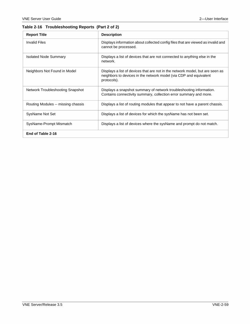
VNE Server User Guide 2—User Interface
Invalid Files Displays information about collected config files that are viewed as invalid and cannot be processed.
Isolated Node Summary Displays a list of devices that are not connected to anything else in the network.
Neighbors Not Found in Model Displays a list of devices that are not in the network model, but are seen as neighbors to devices in the network model (via CDP and equivalent protocols).
Network Troubleshooting Snapshot Displays a snapshot summary of network troubleshooting information. Contains connectivity summary, collection error summary and more.
Routing Modules -- missing chassis Displays a list of routing modules that appear to not have a parent chassis.
SysName Not Set Displays a list of devices for which the sysName has not been set.
SysName-Prompt Mismatch Displays a list of devices where the sysName and prompt do not match.
End of Table 2-16
Table 2-16 Troubleshooting Reports (Part 2 of 2)
Report Title Description
VNE Server/Release 3.5 VNE-2-59
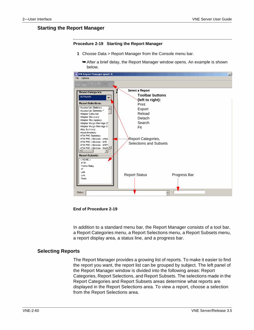
2—User Interface VNE Server User Guide
Starting the Report Manager
Procedure 2-19 Starting the Report Manager
1 Choose Data > Report Manager from the Console menu bar.
➥ After a brief delay, the Report Manager window opens. An example is shown below.
End of Procedure 2-19
In addition to a standard menu bar, the Report Manager consists of a tool bar, a Report Categories menu, a Report Selections menu, a Report Subsets menu, a report display area, a status line, and a progress bar.
Selecting Reports
The Report Manager provides a growing list of reports. To make it easier to find the report you want, the report list can be grouped by subject. The left panel of the Report Manager window is divided into the following areas: Report Categories, Report Selections, and Report Subsets. The selections made in the Report Categories and Report Subsets areas determine what reports are displayed in the Report Selections area. To view a report, choose a selection from the Report Selections area.
Toolbar buttons (left to right):PrintExportReloadDetachSearchFit
Report Status Progress Bar
Report Categories, Selections and Subsets
VNE-2-60 VNE Server/Release 3.5
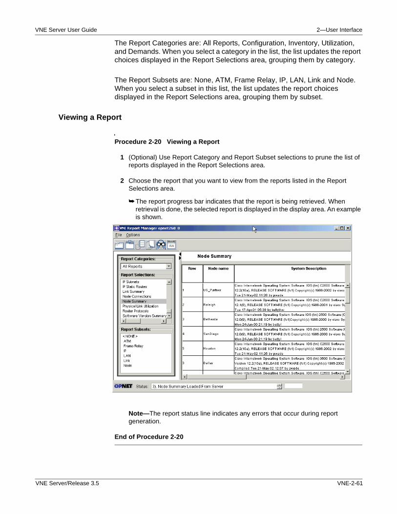
VNE Server User Guide 2—User Interface
The Report Categories are: All Reports, Configuration, Inventory, Utilization, and Demands. When you select a category in the list, the list updates the report choices displayed in the Report Selections area, grouping them by category.
The Report Subsets are: None, ATM, Frame Relay, IP, LAN, Link and Node. When you select a subset in this list, the list updates the report choices displayed in the Report Selections area, grouping them by subset.
Viewing a Report
Procedure 2-20 Viewing a Report
1 (Optional) Use Report Category and Report Subset selections to prune the list of reports displayed in the Report Selections area.
2 Choose the report that you want to view from the reports listed in the Report Selections area.
➥ The report progress bar indicates that the report is being retrieved. When retrieval is done, the selected report is displayed in the display area. An example is shown.
Note—The report status line indicates any errors that occur during report generation.
End of Procedure 2-20
VNE Server/Release 3.5 VNE-2-61
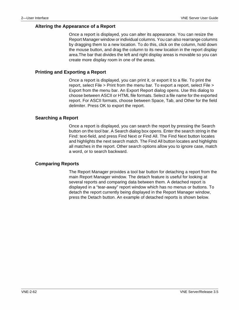
2—User Interface VNE Server User Guide
Altering the Appearance of a Report
Once a report is displayed, you can alter its appearance. You can resize the Report Manager window or individual columns. You can also rearrange columns by dragging them to a new location. To do this, click on the column, hold down the mouse button, and drag the column to its new location in the report display area.The bar that divides the left and right display areas is movable so you can create more display room in one of the areas.
Printing and Exporting a Report
Once a report is displayed, you can print it, or export it to a file. To print the report, select File > Print from the menu bar. To export a report, select File > Export from the menu bar. An Export Report dialog opens. Use this dialog to choose between ASCII or HTML file formats. Select a file name for the exported report. For ASCII formats, choose between Space, Tab, and Other for the field delimiter. Press OK to export the report.
Searching a Report
Once a report is displayed, you can search the report by pressing the Search button on the tool bar. A Search dialog box opens. Enter the search string in the Find: text-field, and press Find Next or Find All. The Find Next button locates and highlights the next search match. The Find All button locates and highlights all matches in the report. Other search options allow you to ignore case, match a word, or to search backward.
Comparing Reports
The Report Manager provides a tool bar button for detaching a report from the main Report Manager window. The detach feature is useful for looking at several reports and comparing data between them. A detached report is displayed in a “tear-away” report window which has no menus or buttons. To detach the report currently being displayed in the Report Manager window, press the Detach button. An example of detached reports is shown below.
VNE-2-62 VNE Server/Release 3.5
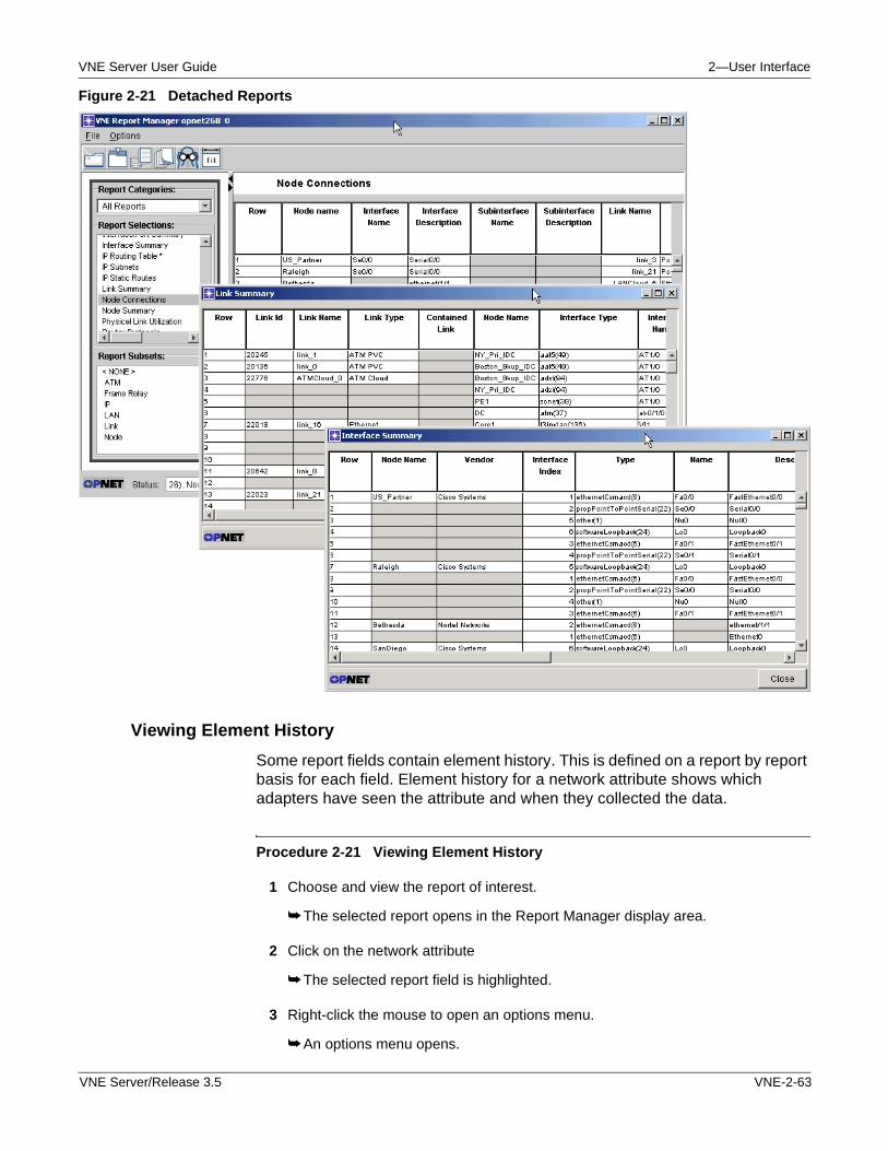
VNE Server User Guide 2—User Interface
Figure 2-21 Detached Reports
Viewing Element History
Some report fields contain element history. This is defined on a report by report basis for each field. Element history for a network attribute shows which adapters have seen the attribute and when they collected the data.
Procedure 2-21 Viewing Element History
1 Choose and view the report of interest.
➥ The selected report opens in the Report Manager display area.
2 Click on the network attribute
➥ The selected report field is highlighted.
3 Right-click the mouse to open an options menu.
➥ An options menu opens.
VNE Server/Release 3.5 VNE-2-63
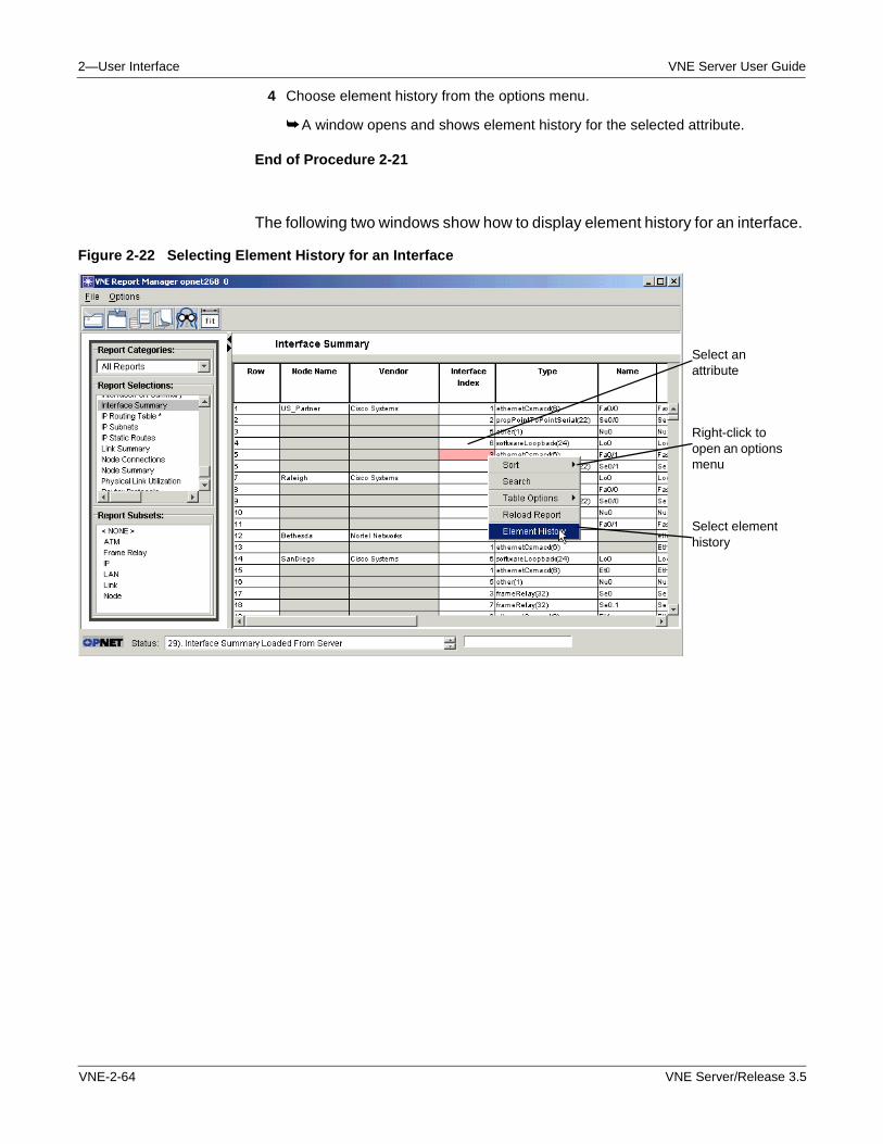
2—User Interface VNE Server User Guide
4 Choose element history from the options menu.
➥ A window opens and shows element history for the selected attribute.
End of Procedure 2-21
The following two windows show how to display element history for an interface.
Figure 2-22 Selecting Element History for an Interface
Select an attribute
Right-click to open an options menu
Select element history
VNE-2-64 VNE Server/Release 3.5
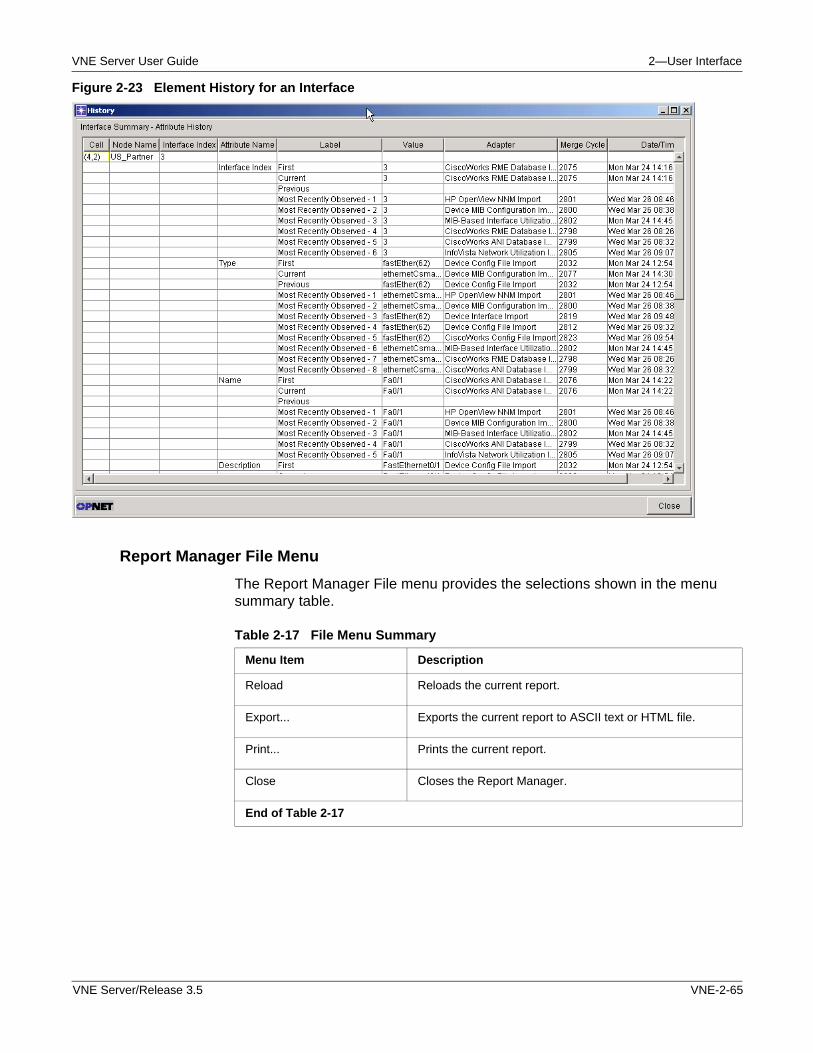
VNE Server User Guide 2—User Interface
Figure 2-23 Element History for an Interface
Report Manager File Menu
The Report Manager File menu provides the selections shown in the menu summary table.
Table 2-17 File Menu Summary
Menu Item Description
Reload Reloads the current report.
Export... Exports the current report to ASCII text or HTML file.
Print... Prints the current report.
Close Closes the Report Manager.
End of Table 2-17
VNE Server/Release 3.5 VNE-2-65
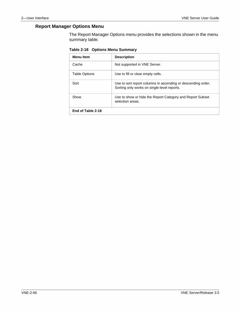
2—User Interface VNE Server User Guide
Report Manager Options Menu
The Report Manager Options menu provides the selections shown in the menu summary table.
Table 2-18 Options Menu Summary
Menu Item Description
Cache Not supported in VNE Server.
Table Options Use to fill or clear empty cells.
Sort Use to sort report columns in ascending or descending order. Sorting only works on single-level reports.
Show Use to show or hide the Report Category and Report Subset selection areas.
End of Table 2-18
VNE-2-66 VNE Server/Release 3.5
VNE Server User Guide 2—User Interface
Network Browser
The Network Browser provides a Windows Explorer style UI for viewing your network. The browser is updated dynamically as network data changes occur. The browser window is divided into 2 panels: navigation and display.
The navigation panel provides an expandable treeview of your network. At the top level of the view is the network. The network consists of devices, which contain interfaces, interface properties, protocol configuration, and many other properties. The network also contains links, VLANS and clouds. Network elements selected in the navigation panel are shown in the display panel.
You can also use the Network Browser to delete selected items from the network model and to also block import of model attributes and even entire devices from one or more sources.
Starting the Network Browser
Procedure 2-22 Starting the Network Browser
1 Choose Data > Network Browser from the Console menu bar.
➥ After a brief delay, the Network Browser window opens.
Note—When the Network Browser first opens, only the top level Root_Network is visible. Click on the expansion handle, or double-click on the Root_Network to expand the view to show all network devices and links. Repeat this process to expand any property in the network tree which contains other properties.
End of Procedure 2-22
Once the browser is open and a network element is selected, data pertaining to the element appears in the display panel with the following fields:
• Name—The name of the displayed element.
• Type—The type of element: Interface, Configuration, Attribute, etc.
• Current Value—The current value of the element.
• Previous Value—The previous value of the element.
• First Value—The first observed value of the element.
• Observed Value—A list of observed values from each source adapter.
VNE Server/Release 3.5 VNE-2-67
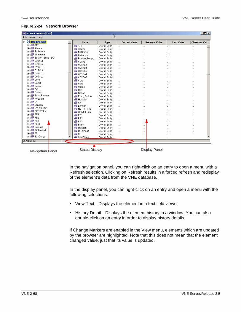
2—User Interface VNE Server User Guide
Figure 2-24 Network Browser
In the navigation panel, you can right-click on an entry to open a menu with a Refresh selection. Clicking on Refresh results in a forced refresh and redisplay of the element’s data from the VNE database.
In the display panel, you can right-click on an entry and open a menu with the following selections:
• View Text—Displays the element in a text field viewer
• History Detail—Displays the element history in a window. You can also double-click on an entry in order to display history details.
If Change Markers are enabled in the View menu, elements which are updated by the browser are highlighted. Note that this does not mean that the element changed value, just that its value is updated.
Display PanelStatus DisplayNavigation Panel
VNE-2-68 VNE Server/Release 3.5
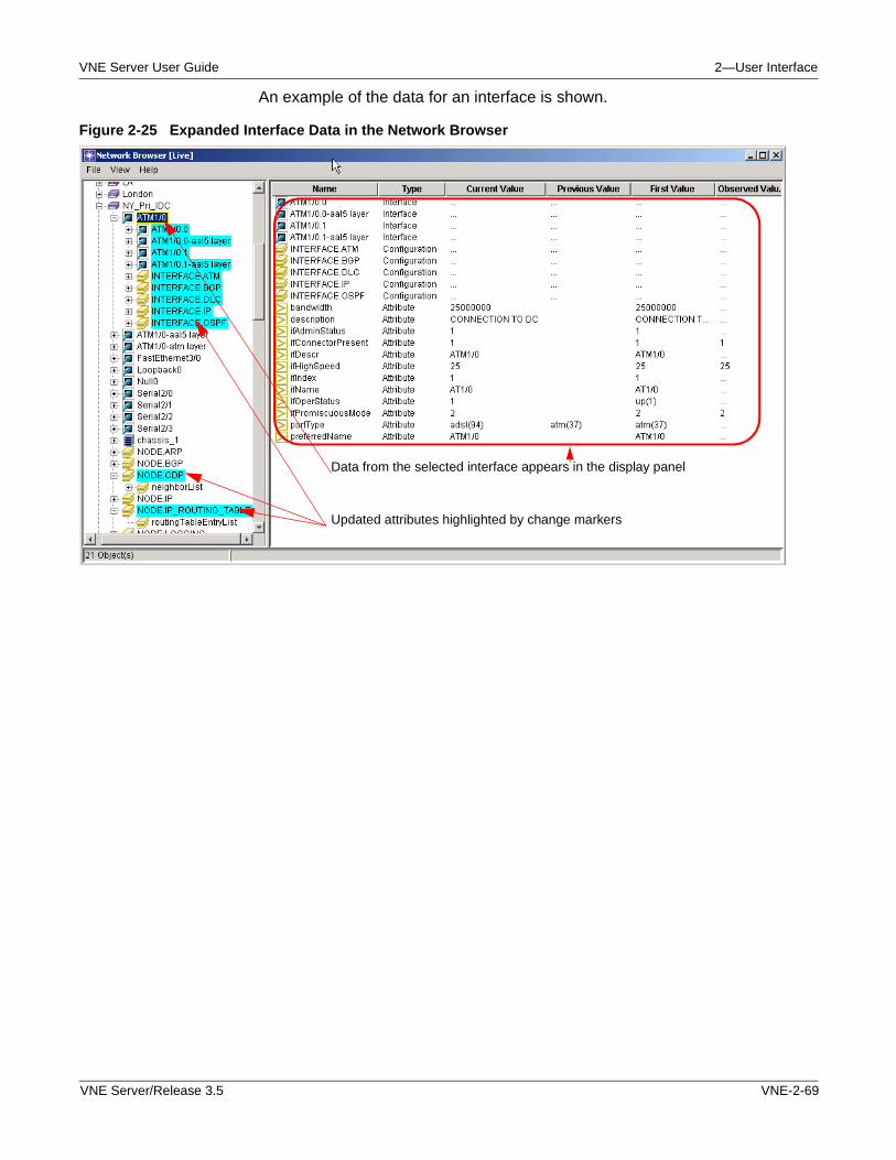
VNE Server User Guide 2—User Interface
An example of the data for an interface is shown.
Figure 2-25 Expanded Interface Data in the Network Browser
Data from the selected interface appears in the display panel
Updated attributes highlighted by change markers
VNE Server/Release 3.5 VNE-2-69
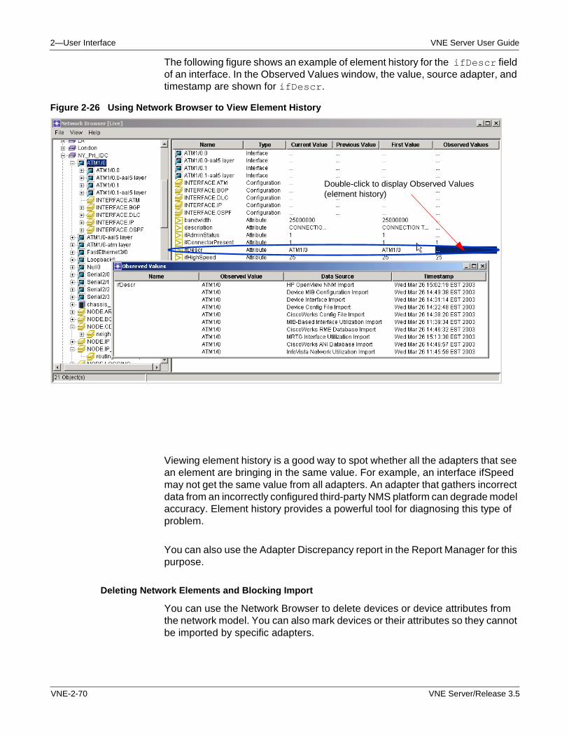
2—User Interface VNE Server User Guide
The following figure shows an example of element history for the ifDescr field of an interface. In the Observed Values window, the value, source adapter, and timestamp are shown for ifDescr.
Figure 2-26 Using Network Browser to View Element History
Viewing element history is a good way to spot whether all the adapters that see an element are bringing in the same value. For example, an interface ifSpeed may not get the same value from all adapters. An adapter that gathers incorrect data from an incorrectly configured third-party NMS platform can degrade model accuracy. Element history provides a powerful tool for diagnosing this type of problem.
You can also use the Adapter Discrepancy report in the Report Manager for this purpose.
Deleting Network Elements and Blocking Import
You can use the Network Browser to delete devices or device attributes from the network model. You can also mark devices or their attributes so they cannot be imported by specific adapters.
Double-click to display Observed Values (element history)
VNE-2-70 VNE Server/Release 3.5
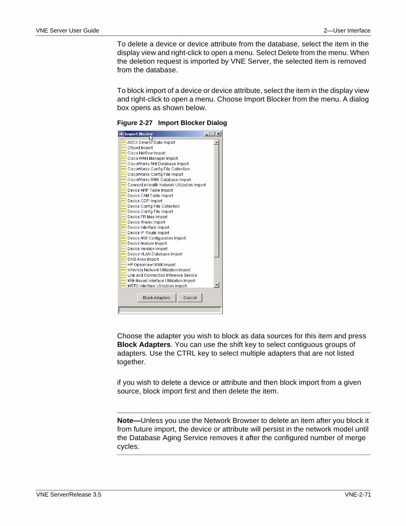
VNE Server User Guide 2—User Interface
To delete a device or device attribute from the database, select the item in the display view and right-click to open a menu. Select Delete from the menu. When the deletion request is imported by VNE Server, the selected item is removed from the database.
To block import of a device or device attribute, select the item in the display view and right-click to open a menu. Choose Import Blocker from the menu. A dialog box opens as shown below.
Figure 2-27 Import Blocker Dialog
Choose the adapter you wish to block as data sources for this item and press Block Adapters. You can use the shift key to select contiguous groups of adapters. Use the CTRL key to select multiple adapters that are not listed together.
if you wish to delete a device or attribute and then block import from a given source, block import first and then delete the item.
Note—Unless you use the Network Browser to delete an item after you block it from future import, the device or attribute will persist in the network model until the Database Aging Service removes it after the configured number of merge cycles.
VNE Server/Release 3.5 VNE-2-71
2—User Interface VNE Server User Guide
Network Browser Menus
The Network Browser has the following menus: File, View, and Help.
• The File menu provides a Close selection that is used to exit the browser.
• The View menu provides the selections shown in the following table.
The Help menu gives you a Request Monitor selection that opens a window displaying the dialog between the Live Network Browser and the internal Live Update Server. The Request Monitor is useful for collecting information for OPNET Technical Support.
For normal operation, leave the Request Monitor closed. To use the Request Monitor, VNE Server must be running in debug mode. This mode is set by the debug property in the Project Properties panel of the Management Console.
WARNING—Do not leave the Request Monitor window open for extended periods of time. Doing so will result in the use of excessive memory resources.
Table 2-19 View Menu Summary
Menu Item Description
Historical Data Enable or disable display of attribute history.
Change Markers Enable or disable display of attribute change (update) markers.
Nodes Enable or disable display of devices (nodes).
Links Enable or disable display of links.
Clear Change Markers Clear any attribute change markers.
End of Table 2-19
VNE-2-72 VNE Server/Release 3.5
VNE Server User Guide 2—User Interface
Preferences
VNE Server adds the following preferences to OPNET.
vne_import.create_serial_cloud
Specifies the default choice for handling the import of Frame Relay-ATM switches or certain inconsistent clouds from VNE Server.
vne_import.dbox_start_function
Specifies the name of the function to invoke to start the VNES import wizard.
vne_import.ior_file
Specifies the IOR file that stores information about connecting to VNE Server.
vne_import.post_operation_function
Specifies the name of the function used to perform operations after a VNES import.
vne_import.post_operation_library
Specifies the name of the library containing the post-operation function specified by vne_import.post_operation_function.
Type string
Default Value “PARTIAL”
Type string
Default Value “Vne_Import_Dbox_Start”
Type string
Default Value “”
Type string
Default Value “Vne_Import_Post_Operation”
Type string
Default Value “vne_import_postproc”
VNE Server/Release 3.5 VNE-2-73
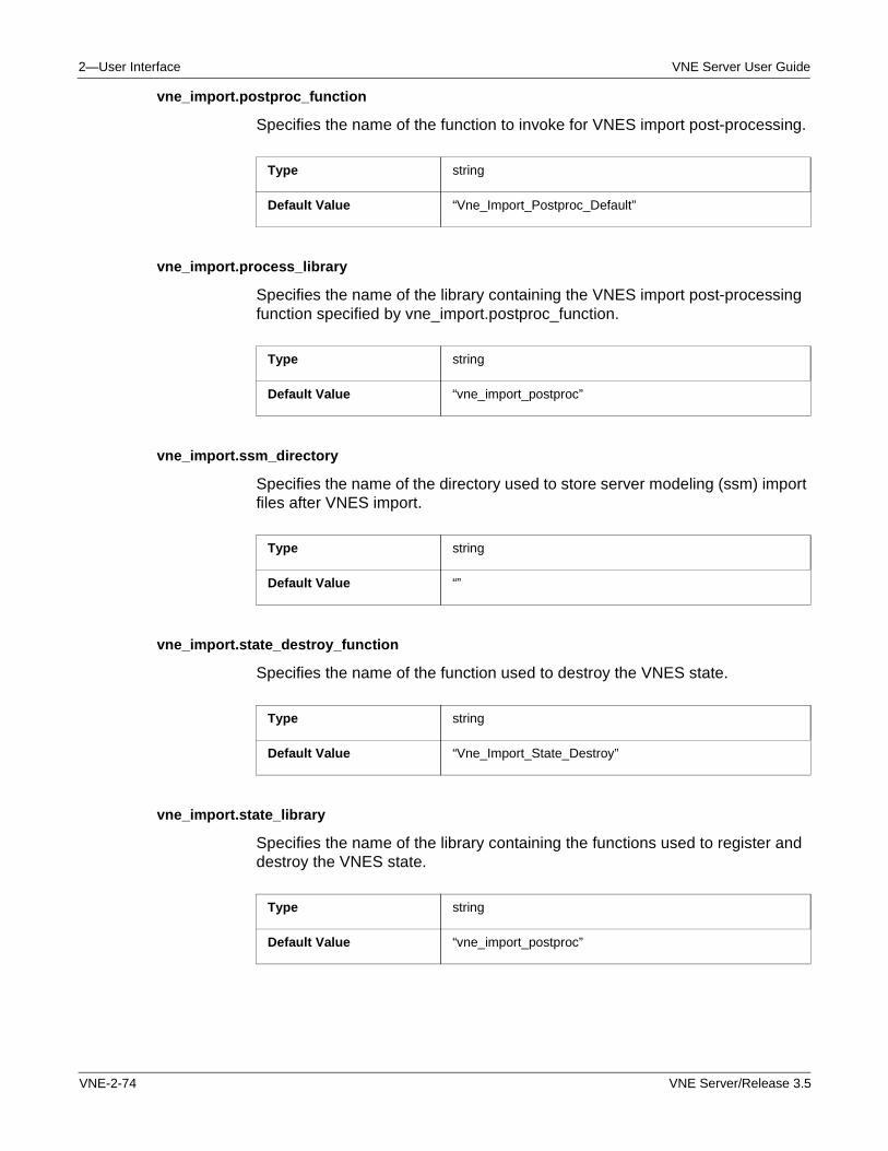
2—User Interface VNE Server User Guide
vne_import.postproc_function
Specifies the name of the function to invoke for VNES import post-processing.
vne_import.process_library
Specifies the name of the library containing the VNES import post-processing function specified by vne_import.postproc_function.
vne_import.ssm_directory
Specifies the name of the directory used to store server modeling (ssm) import files after VNES import.
vne_import.state_destroy_function
Specifies the name of the function used to destroy the VNES state.
vne_import.state_library
Specifies the name of the library containing the functions used to register and destroy the VNES state.
Type string
Default Value “Vne_Import_Postproc_Default”
Type string
Default Value “vne_import_postproc”
Type string
Default Value “”
Type string
Default Value “Vne_Import_State_Destroy”
Type string
Default Value “vne_import_postproc”
VNE-2-74 VNE Server/Release 3.5
VNE Server User Guide 2—User Interface
vne_import.state_register_function
Specifies the name of the function used to register the VNES state.
Type string
Default Value “Vne_Import_State_Register”
VNE Server/Release 3.5 VNE-2-75

2—User Interface VNE Server User Guide
VNE-2-76 VNE Server/Release 3.5
VNE Server User Guide 3—Adapters and Services
3 Adapters and Services
Introduction
As described in the Overview chapter, VNE Server provides a comprehensive selection of data collection adapters and framework services. This chapter describes how to configure and test each adapter and service provided by VNE Server.
Device Config File Collection
The Device Config File Collection adapter collects configuration data; including config files, interface tables, interface index tables, software version, and other data; directly from network devices using the command line interface (CLI). Collected data are stored for subsequent import by the appropriate import adapter. There is a separate import adapter for each data type collected: Device Config File Import, Device ifIndex Import, etc.
A user generated device access information file, called the Device Info File, directs the adapter to each device in the network. The Device Info File contains all the information that VNE Server requires to log on to each device and obtain configuration information. The information includes hostname, IP address, passwords, and vendor. The Device Info File is discussed in more detail in section Device and Platform Info on page VNE-2-41 of the User Interface chapter.
When the Device Config File Collection adapter remotely connects to a device, it issues the vendor-specific commands for collecting the configuration information for the device. The adapter captures the output from these commands and stores it in files at a default location within the VNE Server temporary directory. The vendor devices currently supported by VNE Server are: Cisco routers (IOS and Integrated IOS), Cisco Catalyst devices (IOS and CatOS), Cisco PIX firewalls, Extreme Networks devices, Foundry devices, Juniper routers (JUNOS), Juniper ERX, Nortel Networks routers (BayRS), Nortel Networks Passport 8000 series devices, and Check Point FireWall-1.
VNE Server/Release 3.5 VNE-3-1
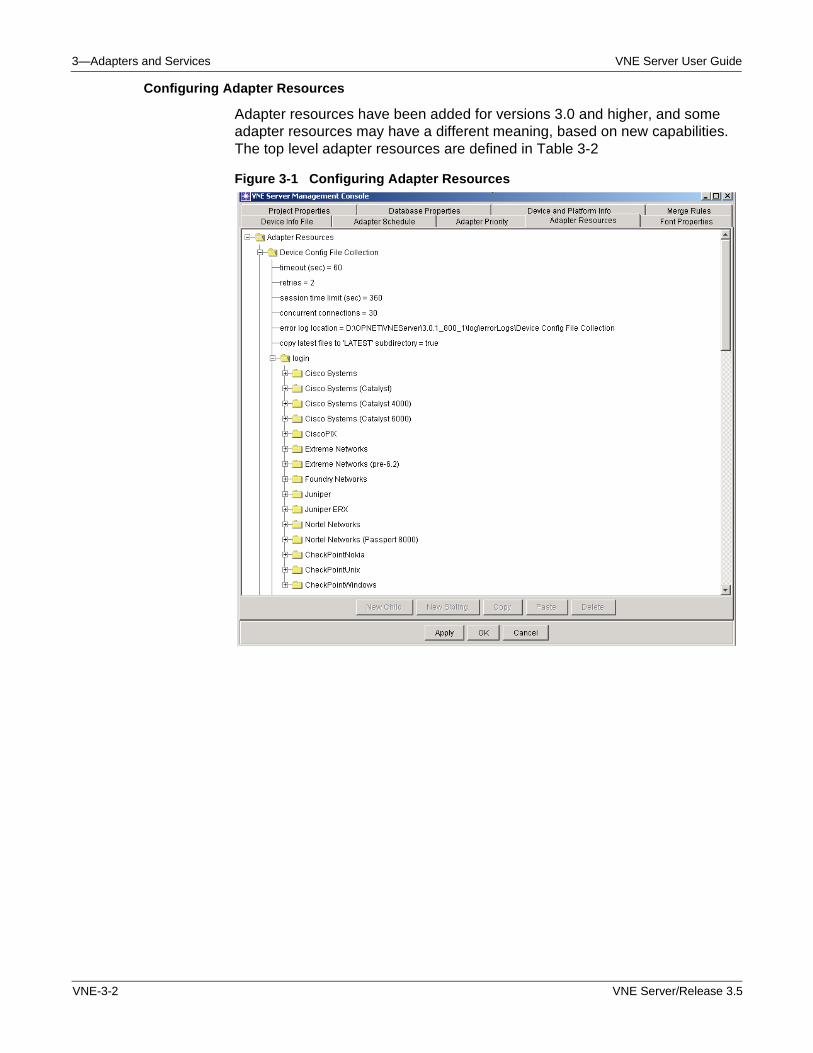
3—Adapters and Services VNE Server User Guide
Configuring Adapter Resources
Adapter resources have been added for versions 3.0 and higher, and some adapter resources may have a different meaning, based on new capabilities. The top level adapter resources are defined in Table 3-2
Figure 3-1 Configuring Adapter Resources
VNE-3-2 VNE Server/Release 3.5
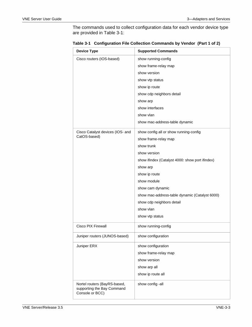
VNE Server User Guide 3—Adapters and Services
The commands used to collect configuration data for each vendor device type are provided in Table 3-1:
Table 3-1 Configuration File Collection Commands by Vendor (Part 1 of 2)
Device Type Supported Commands
Cisco routers (IOS-based) show running-config
show frame-relay map
show version
show vtp status
show ip route
show cdp neighbors detail
show arp
show interfaces
show vlan
show mac-address-table dynamic
Cisco Catalyst devices (IOS- and CatOS-based)
show config all or show running-config
show frame-relay map
show trunk
show version
show ifindex (Catalyst 4000: show port ifindex)
show arp
show ip route
show module
show cam dynamic
show mac-address-table dynamic (Catalyst 6000)
show cdp neighbors detail
show vlan
show vtp status
Cisco PIX Firewall show running-config
Juniper routers (JUNOS-based) show configuration
Juniper ERX show configuration
show frame-relay map
show version
show arp all
show ip route all
Nortel routers (BayRS-based, supporting the Bay Command Console or BCC)
show config -all
VNE Server/Release 3.5 VNE-3-3
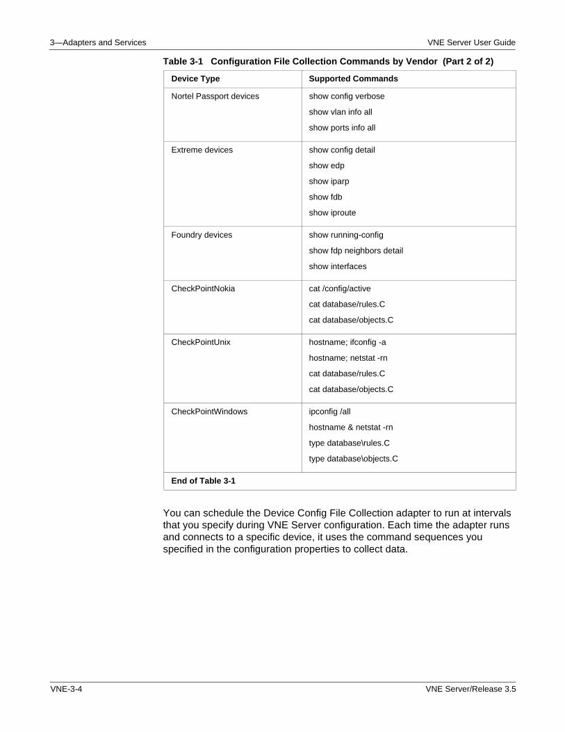
3—Adapters and Services VNE Server User Guide
You can schedule the Device Config File Collection adapter to run at intervals that you specify during VNE Server configuration. Each time the adapter runs and connects to a specific device, it uses the command sequences you specified in the configuration properties to collect data.
Nortel Passport devices show config verbose
show vlan info all
show ports info all
Extreme devices show config detail
show edp
show iparp
show fdb
show iproute
Foundry devices show running-config
show fdp neighbors detail
show interfaces
CheckPointNokia cat /config/active
cat database/rules.C
cat database/objects.C
CheckPointUnix hostname; ifconfig -a
hostname; netstat -rn
cat database/rules.C
cat database/objects.C
CheckPointWindows ipconfig /all
hostname & netstat -rn
type database\rules.C
type database\objects.C
End of Table 3-1
Table 3-1 Configuration File Collection Commands by Vendor (Part 2 of 2)
Device Type Supported Commands
VNE-3-4 VNE Server/Release 3.5
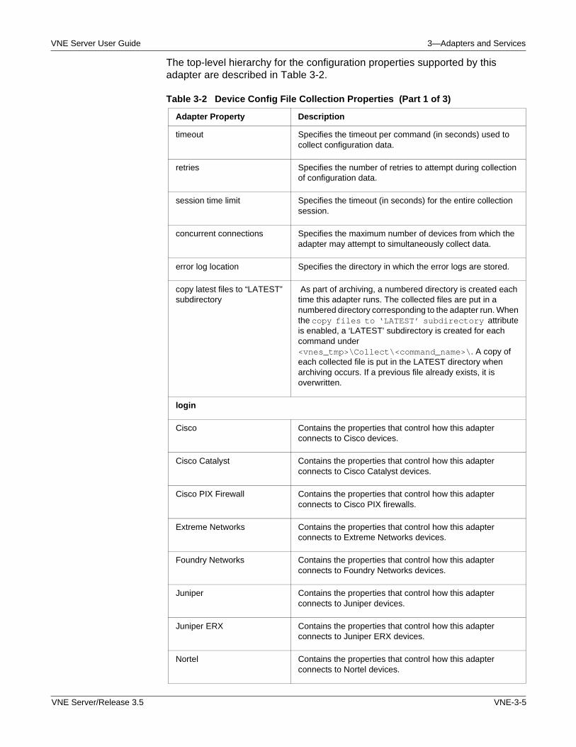
VNE Server User Guide 3—Adapters and Services
The top-level hierarchy for the configuration properties supported by this adapter are described in Table 3-2.
Table 3-2 Device Config File Collection Properties (Part 1 of 3)
Adapter Property Description
timeout Specifies the timeout per command (in seconds) used to collect configuration data.
retries Specifies the number of retries to attempt during collection of configuration data.
session time limit Specifies the timeout (in seconds) for the entire collection session.
concurrent connections Specifies the maximum number of devices from which the adapter may attempt to simultaneously collect data.
error log location Specifies the directory in which the error logs are stored.
copy latest files to “LATEST” subdirectory
As part of archiving, a numbered directory is created each time this adapter runs. The collected files are put in a numbered directory corresponding to the adapter run. When the copy files to ‘LATEST’ subdirectory attribute is enabled, a ‘LATEST’ subdirectory is created for each command under <vnes_tmp>\Collect\<command_name>\. A copy of each collected file is put in the LATEST directory when archiving occurs. If a previous file already exists, it is overwritten.
login
Cisco Contains the properties that control how this adapter connects to Cisco devices.
Cisco Catalyst Contains the properties that control how this adapter connects to Cisco Catalyst devices.
Cisco PIX Firewall Contains the properties that control how this adapter connects to Cisco PIX firewalls.
Extreme Networks Contains the properties that control how this adapter connects to Extreme Networks devices.
Foundry Networks Contains the properties that control how this adapter connects to Foundry Networks devices.
Juniper Contains the properties that control how this adapter connects to Juniper devices.
Juniper ERX Contains the properties that control how this adapter connects to Juniper ERX devices.
Nortel Contains the properties that control how this adapter connects to Nortel devices.
VNE Server/Release 3.5 VNE-3-5
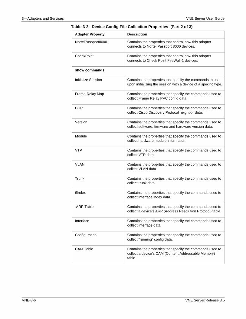
3—Adapters and Services VNE Server User Guide
NortelPassport8000 Contains the properties that control how this adapter connects to Nortel Passport 8000 devices.
CheckPoint Contains the properties that control how this adapter connects to Check Point FireWall-1 devices.
show commands
Initialize Session Contains the properties that specify the commands to use upon initializing the session with a device of a specific type.
Frame-Relay Map Contains the properties that specify the commands used to collect Frame Relay PVC config data.
CDP Contains the properties that specify the commands used to collect Cisco Discovery Protocol neighbor data.
Version Contains the properties that specify the commands used to collect software, firmware and hardware version data.
Module Contains the properties that specify the commands used to collect hardware module information.
VTP Contains the properties that specify the commands used to collect VTP data.
VLAN Contains the properties that specify the commands used to collect VLAN data.
Trunk Contains the properties that specify the commands used to collect trunk data.
ifIndex Contains the properties that specify the commands used to collect interface index data.
ARP Table Contains the properties that specify the commands used to collect a device’s ARP (Address Resolution Protocol) table.
Interface Contains the properties that specify the commands used to collect interface data.
Configuration Contains the properties that specify the commands used to collect “running” config data.
CAM Table Contains the properties that specify the commands used to collect a device’s CAM (Content Addressable Memory) table.
Table 3-2 Device Config File Collection Properties (Part 2 of 3)
Adapter Property Description
VNE-3-6 VNE Server/Release 3.5
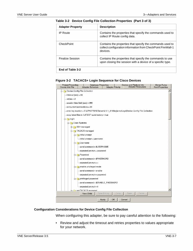
VNE Server User Guide 3—Adapters and Services
Figure 3-2 TACACS+ Login Sequence for Cisco Devices
Configuration Considerations for Device Config File Collection
When configuring this adapter, be sure to pay careful attention to the following:
• Review and adjust the timeout and retries properties to values appropriate for your network.
IP Route Contains the properties that specify the commands used to collect IP Route config data.
CheckPoint Contains the properties that specify the commands used to collect configuration information from CheckPoint FireWall-1 devices.
Finalize Session Contains the properties that specify the commands to use upon closing the session with a device of a specific type.
End of Table 3-2
Table 3-2 Device Config File Collection Properties (Part 3 of 3)
Adapter Property Description
VNE Server/Release 3.5 VNE-3-7
3—Adapters and Services VNE Server User Guide
• Review the login properties for each device vendor in your network.
The login command and response sequence programmed in the login properties should match the sequence configured for your devices.
Check the command sequence for all supported access methods (SSH, TACACS+, etc.) under each vendor.
• Review the show commands properties for each command and vendor.
The command sequence should match the sequence configured for your devices.
Note—If you have mixed login or show command sequences for a specific device type in your network, you must create new device types so that all the command sequences are defined. Each device in the device info file should have the Device Access Script field set to a device type (vendor or vendor subtype).
Configuring Device Login Properties
Table 3-2 shows the top-level hierarchy for this adapter’s properties. All the properties are organized under login and show commands property trees. Under the login tree, a property tree exists for each vendor. This tree contains properties that hold the vendor-specific commands and expected responses used to access and retrieve data from the device. Under each configuration command in the show commands tree, vendor-specific property trees hold the commands and responses used to collect configuration data.
Figure 3-2 window shows an example of the command and response sequence used to access TACACS+ managed Cisco devices. Each access method—SSH, TACACS+, and others—has a command sequence defined for each vendor. Notice that the login command sequence contains references to $USERNAME, $PASSWORD, and $ENABLE_PASSWORD variables. When a specific device in the network is accessed, these variables are filled in with information for this device that is taken from the device info file. Refer to Device and Platform Info on page VNE-2-41 in the User Interface chapter for more information about the device info file.
After successful login to a device, the adapter should be at the command level in the device where a vendor-specific command, such as show running-config for Cisco devices, can be issued to obtain configuration data. For the adapter to login to the device, each response property, such as initial prompt and expected prompt, must match the text string that is returned by the device. Otherwise login fails, and the VNE Server Event Viewer shows error messages about the failure.
VNE-3-8 VNE Server/Release 3.5
VNE Server User Guide 3—Adapters and Services
Configuring Show Command Properties
Once this adapter has logged into a device, it is ready to submit “show” commands to collect all the specified configuration data. All the configuration commands to be issued against a device are sent during the same telnet or SSH session. The results of each command are stored in a file for each type of “show” command. Each type of show command has its own directory in the VNE Server temp directory under <temp dir>\Collect. The show command storage directories are
• <temp dir>\Collect\ARP
• <temp dir>\Collect\CAM
• <temp dir>\Collect\CDP
• <temp dir>\Collect\CheckPoint
• <temp dir>\Collect\Configs
• <temp dir>\Collect\FRMap
• <temp dir>\Collect\ifIndex
• <temp dir>\Collect\Interface
• <temp dir>\Collect\IPRoute
• <temp dir>\Collect\Module
• <temp dir>\Collect\Trunk
• <temp dir>\Collect\Version
• <temp dir>\Collect\Vlan
• <temp dir>\Collect\VTP
VNE Server/Release 3.5 VNE-3-9
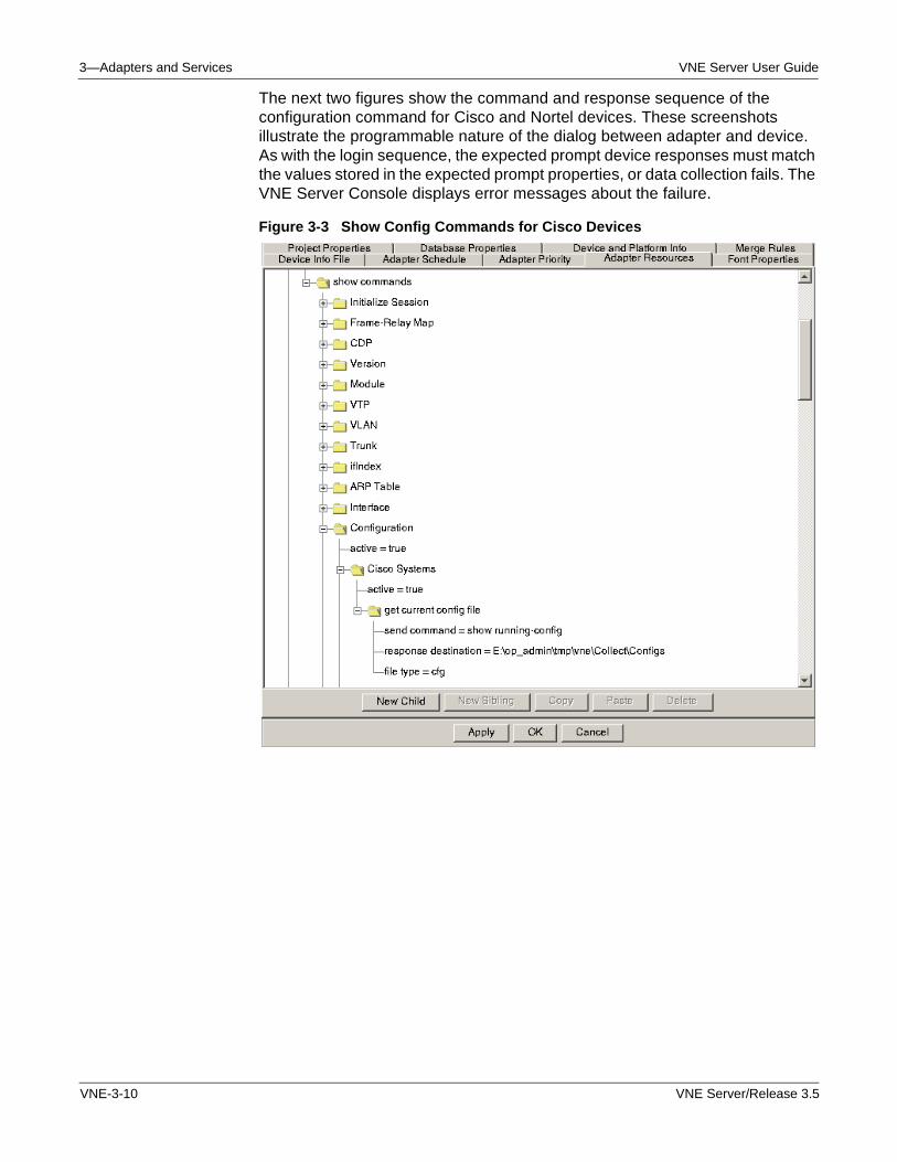
3—Adapters and Services VNE Server User Guide
The next two figures show the command and response sequence of the configuration command for Cisco and Nortel devices. These screenshots illustrate the programmable nature of the dialog between adapter and device. As with the login sequence, the expected prompt device responses must match the values stored in the expected prompt properties, or data collection fails. The VNE Server Console displays error messages about the failure.
Figure 3-3 Show Config Commands for Cisco Devices
VNE-3-10 VNE Server/Release 3.5
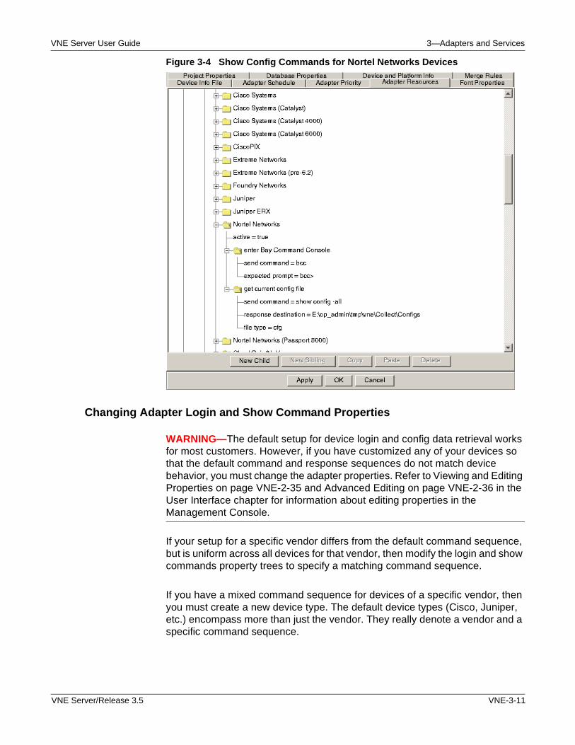
VNE Server User Guide 3—Adapters and Services
Figure 3-4 Show Config Commands for Nortel Networks Devices
Changing Adapter Login and Show Command Properties
WARNING—The default setup for device login and config data retrieval works for most customers. However, if you have customized any of your devices so that the default command and response sequences do not match device behavior, you must change the adapter properties. Refer to Viewing and Editing Properties on page VNE-2-35 and Advanced Editing on page VNE-2-36 in the User Interface chapter for information about editing properties in the Management Console.
If your setup for a specific vendor differs from the default command sequence, but is uniform across all devices for that vendor, then modify the login and show commands property trees to specify a matching command sequence.
If you have a mixed command sequence for devices of a specific vendor, then you must create a new device type. The default device types (Cisco, Juniper, etc.) encompass more than just the vendor. They really denote a vendor and a specific command sequence.
VNE Server/Release 3.5 VNE-3-11
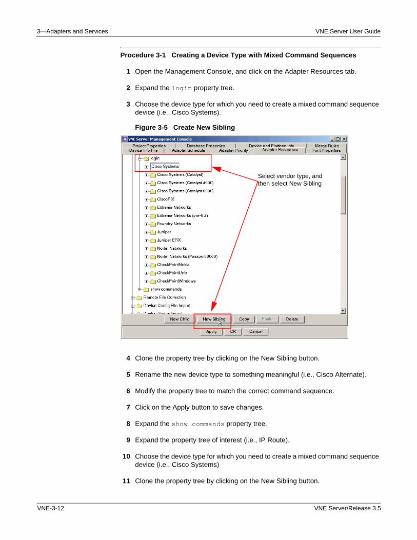
3—Adapters and Services VNE Server User Guide
Procedure 3-1 Creating a Device Type with Mixed Command Sequences
1 Open the Management Console, and click on the Adapter Resources tab.
2 Expand the login property tree.
3 Choose the device type for which you need to create a mixed command sequence device (i.e., Cisco Systems).
Figure 3-5 Create New Sibling
4 Clone the property tree by clicking on the New Sibling button.
5 Rename the new device type to something meaningful (i.e., Cisco Alternate).
6 Modify the property tree to match the correct command sequence.
7 Click on the Apply button to save changes.
8 Expand the show commands property tree.
9 Expand the property tree of interest (i.e., IP Route).
10 Choose the device type for which you need to create a mixed command sequence device (i.e., Cisco Systems)
11 Clone the property tree by clicking on the New Sibling button.
Select vendor type, and then select New Sibling
VNE-3-12 VNE Server/Release 3.5
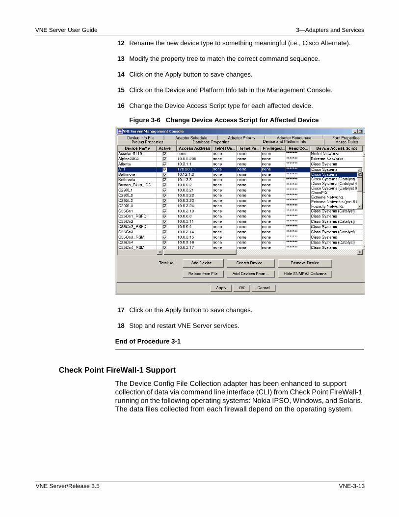
VNE Server User Guide 3—Adapters and Services
12 Rename the new device type to something meaningful (i.e., Cisco Alternate).
13 Modify the property tree to match the correct command sequence.
14 Click on the Apply button to save changes.
15 Click on the Device and Platform Info tab in the Management Console.
16 Change the Device Access Script type for each affected device.
Figure 3-6 Change Device Access Script for Affected Device
17 Click on the Apply button to save changes.
18 Stop and restart VNE Server services.
End of Procedure 3-1
Check Point FireWall-1 Support
The Device Config File Collection adapter has been enhanced to support collection of data via command line interface (CLI) from Check Point FireWall-1 running on the following operating systems: Nokia IPSO, Windows, and Solaris. The data files collected from each firewall depend on the operating system.
VNE Server/Release 3.5 VNE-3-13
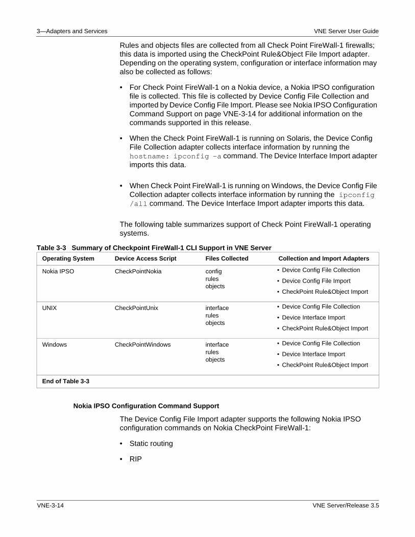
3—Adapters and Services VNE Server User Guide
Rules and objects files are collected from all Check Point FireWall-1 firewalls; this data is imported using the CheckPoint Rule&Object File Import adapter. Depending on the operating system, configuration or interface information may also be collected as follows:
• For Check Point FireWall-1 on a Nokia device, a Nokia IPSO configuration file is collected. This file is collected by Device Config File Collection and imported by Device Config File Import. Please see Nokia IPSO Configuration Command Support on page VNE-3-14 for additional information on the commands supported in this release.
• When the Check Point FireWall-1 is running on Solaris, the Device Config File Collection adapter collects interface information by running the hostname: ipconfig -a command. The Device Interface Import adapter imports this data.
• When Check Point FireWall-1 is running on Windows, the Device Config File Collection adapter collects interface information by running the ipconfig /all command. The Device Interface Import adapter imports this data.
The following table summarizes support of Check Point FireWall-1 operating systems.
Table 3-3 Summary of Checkpoint FireWall-1 CLI Support in VNE Server
Nokia IPSO Configuration Command Support
The Device Config File Import adapter supports the following Nokia IPSO configuration commands on Nokia CheckPoint FireWall-1:
• Static routing
• RIP
Operating System Device Access Script Files Collected Collection and Import Adapters
Nokia IPSO CheckPointNokia configrulesobjects
• Device Config File Collection
• Device Config File Import
• CheckPoint Rule&Object Import
UNIX CheckPointUnix interfacerulesobjects
• Device Config File Collection
• Device Interface Import
• CheckPoint Rule&Object Import
Windows CheckPointWindows interfacerulesobjects
• Device Config File Collection
• Device Interface Import
• CheckPoint Rule&Object Import
End of Table 3-3
VNE-3-14 VNE Server/Release 3.5
VNE Server User Guide 3—Adapters and Services
• PIM
• DVMRP
These IPSO commands are not supported at this time:
• OSPF
• BGP
• IGMP
Support for Juniper ERX
The Device Config File Collection adapter has been enhanced to support collection of configuration files via command line interface (CLI) for Juniper ERX devices. Import the collected data using the Device Config File Import adapter. Please review the Restrictions and Limitations section on Duplicate IP Addresses on page VNE-A-6.
WARNING—Please note that the Device MIB Configuration Import adapter does not provide support for Juniper ERX. When you configure VNE Server collection in the Management Console Device and Platform Info tab, do not make the Collect MIB column active for a Juniper ERX device.
Device Configuration Import Adapters
The Device Config File Collection adapter executes multiple configuration collection commands for each device it accesses. The resulting configuration files are written to the VNE Server temp dir environment. An import adapter exists for each file type. These import adapters are
• Device Config File Import
• Device ifIndex Import
• Device FR Map Import
• Device Version Import
• Device IP Route Import
• Device CDP Import
• Device ARP Table Import
• Device Interface Import
• Device Module Import
• Device VTP Status Import
• Device CAM Table Import
VNE Server/Release 3.5 VNE-3-15
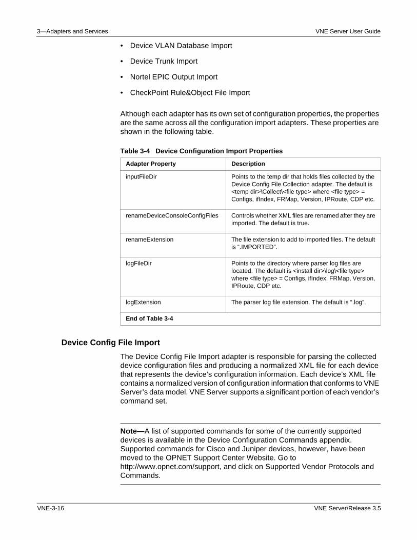
3—Adapters and Services VNE Server User Guide
• Device VLAN Database Import
• Device Trunk Import
• Nortel EPIC Output Import
• CheckPoint Rule&Object File Import
Although each adapter has its own set of configuration properties, the properties are the same across all the configuration import adapters. These properties are shown in the following table.
Device Config File Import
The Device Config File Import adapter is responsible for parsing the collected device configuration files and producing a normalized XML file for each device that represents the device’s configuration information. Each device’s XML file contains a normalized version of configuration information that conforms to VNE Server’s data model. VNE Server supports a significant portion of each vendor’s command set.
Note—A list of supported commands for some of the currently supported devices is available in the Device Configuration Commands appendix. Supported commands for Cisco and Juniper devices, however, have been moved to the OPNET Support Center Website. Go to http://www.opnet.com/support, and click on Supported Vendor Protocols and Commands.
Table 3-4 Device Configuration Import Properties
Adapter Property Description
inputFileDir Points to the temp dir that holds files collected by the Device Config File Collection adapter. The default is <temp dir>\Collect\<file type> where <file type> = Configs, ifIndex, FRMap, Version, IPRoute, CDP etc.
renameDeviceConsoleConfigFiles Controls whether XML files are renamed after they are imported. The default is true.
renameExtension The file extension to add to imported files. The default is “.IMPORTED”.
logFileDir Points to the directory where parser log files are located. The default is <install dir>\log\<file type> where <file type> = Configs, ifIndex, FRMap, Version, IPRoute, CDP etc.
logExtension The parser log file extension. The default is “.log”.
End of Table 3-4
VNE-3-16 VNE Server/Release 3.5
VNE Server User Guide 3—Adapters and Services
The XML file generated for each device is stored in the VNE Server temp directory (defaults to: C:\op_admin\tmp\vne). As with the other adapters, the Device Config File Import adapter is scheduled to run at regular intervals and will overwrite any previously existing file from the same device.
Expanded Command Support
Expanded command support for Cisco IOS-based, Cisco CatOS-based, and Juniper JUNOS-based devices includes
• AAA, RADIUS, TACACS+ commands
• GRE tunnel command support
• IPsec tunnel command support
• RSRB/DLSW+ command support
• IP Multicast command support
• EtherChannel support
• VoIP command support
• MPLS/VPN command support
• CatOS management interface support
VNE Server/Release 3.5 VNE-3-17
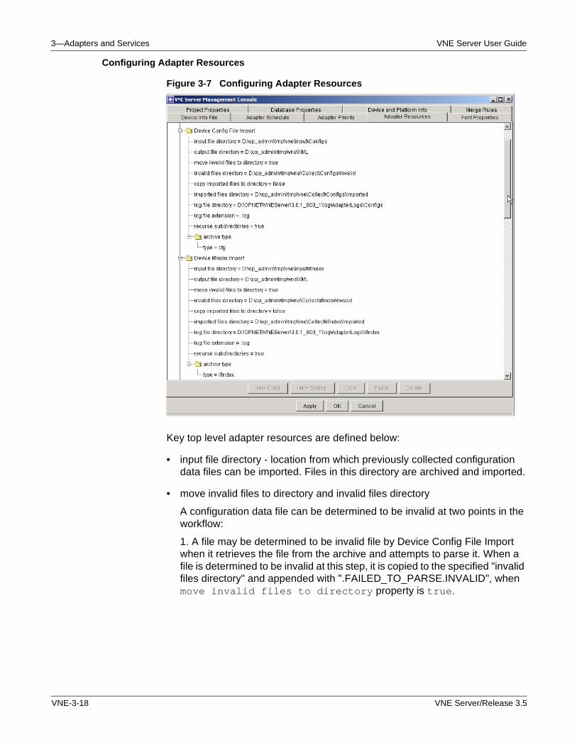
3—Adapters and Services VNE Server User Guide
Configuring Adapter Resources
Figure 3-7 Configuring Adapter Resources
Key top level adapter resources are defined below:
• input file directory - location from which previously collected configuration data files can be imported. Files in this directory are archived and imported.
• move invalid files to directory and invalid files directory
A configuration data file can be determined to be invalid at two points in the workflow:
1. A file may be determined to be invalid file by Device Config File Import when it retrieves the file from the archive and attempts to parse it. When a file is determined to be invalid at this step, it is copied to the specified "invalid files directory" and appended with ".FAILED_TO_PARSE.INVALID", when move invalid files to directory property is true.
VNE-3-18 VNE Server/Release 3.5
VNE Server User Guide 3—Adapters and Services
2. Using pre-collected files, a file may be determined to be invalid during archiving. When move invalid files to directory property is true, the invalid file is moved to the specified "invalid files directory" and appended with ".FAILED_TO_FIND_DEVICE_ID.INVALID".
• recurse subdirectories—(relevant when importing pre-collected files from the input file directory.) When set to true, all files in the "input files directory" and its subdirectories will be archived and imported.
The following Device Config File Import attributes are no longer present as of version 3.0:
• rename DeviceConsoleConfigFiles
• renameExtension
• incompleteExtension
They are replaced by the following properties defined in Project Properties > VNESfeatures > versionControl.
• rename collected files after archiving—controls whether files are renamed as they are archived. This applies to files that are collected via Device Config File Collection and pre-collected files that are archived by the import adapters.
• rename collected files with this extension—the extension that will be appended to archived files.
• do not import filter—A list of extensions. Files with these extensions will not be archived in the future. This allows users to specify that files in an "input files directory" that have already been renamed as archived, imported, invalid, or incomplete should not be archived again.
Device ifIndex Import
The Device Ifindex Import adapter is responsible for parsing the collected interface index information and producing a normalized XML file for each device representing the device’s interfaces and corresponding interface indices.
Device FR Map Import
The Device FR Map Import adapter is responsible for parsing the collected Frame Relay Map information and producing a normalized XML file for each device representing the device’s frame relay PVC configuration information.
VNE Server/Release 3.5 VNE-3-19
3—Adapters and Services VNE Server User Guide
Device Version Import
The Device Version Import adapter is responsible for parsing the collected device version information and producing a normalized XML file for each device representing the device’s systems description, chassis type, software version, and device identifier.
Device IP Route Import
The Device IP Route Import adapter is responsible for parsing the collected IP routing table information and producing a normalized XML file for each device representing the device’s IP routing table.
Device CDP Import
The Device CDP Import adapter is responsible for parsing the collected Cisco Discovery Protocol neighbor information and producing a normalized XML file for each device representing the device’s neighbors as determined by the Cisco discovery protocol.
The Device CDP Import adapter was enhanced as of version 3.0 to provide the ability to create shell nodes representing neighbor nodes that are reported in the CDP neighbor table but not found in the VNE Server database.
Devices may be added using this method to create a more connected topology, however these devices do not contain any configuration data required for modeling. The only information that VNE Server has for these devices is provided by neighbor information tables and is, therefore, extremely limited. If the missing CDP neighbors are under your administrative control, it is recommended that you create entries for them in the device info file (for VNE Server direct collection), so configuration data can be collected and imported into the VNE Server database the next time the collection and import adapters run.
To enable this feature, open the Management Console and select the Adapter Resources tab. Expand Device CDP Import, and set createCdpNeighbors to true. This feature is disabled by default.
Device ARP Table Import
The Device ARP Table Import adapter is responsible for parsing the collected ARP table information and producing a normalized XML file for each device representing the device’s ARP table.
Device Interface Import
The Device Interface Import adapter is responsible for parsing the collected interface information and producing a normalized XML file for each device representing the device’s interface information.
VNE-3-20 VNE Server/Release 3.5
VNE Server User Guide 3—Adapters and Services
Device Module Import
The Device Module Import adapter is responsible for parsing the collected module information and producing a normalized XML file for each device representing the device’s module information.
Device VTP Status Import
The Device VTP Status Import adapter is responsible for parsing the collected VTP status information and producing a normalized XML file for each device representing the device’s VTP status information.
Device CAM Table Import
The Device CAM Table Import adapter is responsible for parsing the collected CAM table information and producing a normalized XML file for each device representing the device’s CAM table.
Device VLAN Database Import
The Device VLAN Database Import adapter is responsible for parsing the collected VLAN information and producing a normalized XML file for each device representing the device’s VLAN database.
Device Trunk Import
The Device Config File Collection adapter was enhanced to collect the Cisco Catalyst “show trunk” command. The Device Trunk Import adapter has been added to import the collected trunk data. The Device Trunk Import adapter is responsible for parsing the collected trunk information and producing a normalized XML file for each device representing the device’s trunk information.
Nortel EPIC Output Import
The Nortel EPIC Output Import adapter is responsible for parsing collected EPIC files and producing a normalized XML file containing information about each device.
Remote File Collection
The Remote File Collection adapter uses FTP to collect files from other hosts. This adapter is mainly used to collect files for processing by other adapters. Some use cases are
• Retrieve config files from a custom archive environment
• Retrieve interface utilization or traffic flow files from an archive environment
VNE Server/Release 3.5 VNE-3-21
3—Adapters and Services VNE Server User Guide
The Remote File Collection adapter supports file filtering based upon file name prefix and file name extension. When filtering is configured, the only files retrieved are those matching the filter specification.
You can retrieve files from more than one remote directory, using the Management Console to add as many remote directory property trees as you need for your environment. You can also retrieve files from subdirectories under any specified remote directory. Note that when this feature is enabled, directory hierarchy is not preserved. All collected files are written to the specified storage directory.
Note—When specifying directory paths, always provide the full path.
Key Concept—The Remote File Collection adapter is typically used to copy files from other hosts that have been collected by third-party or “home grown” applications. Configure this adapter to copy the data files to the import file directory of the adapter that will process the files. For example, if you are collecting files for Device Config File Import and the other show command adapters, copy them to the appropriate <tempdir>\Collect directories. You can schedule this adapter to run based upon time or event triggers. Use event triggering and the Finish Import event raised by this adapter to trigger adapters to run and process data files collected by this adapter.
The configuration properties for this adapter are described in the following table.
Table 3-5 Remote File Collection Properties (Part 1 of 2)
Adapter Property Description
sourceList Contains list of remote file servers.
server1
active Controls whether files are collected from this server.
ftp
connectionType Specifies FTP or SFTP as the type of connection.
hostName Specifies the name or address of the file server.
userName Specifies the user name used to login to the server.
password Specifies the password used to login to the server.
timeout(mSec) Specifies the FTP connection timeout value.
retries Specifies the FTP connection retry value.
VNE-3-22 VNE Server/Release 3.5
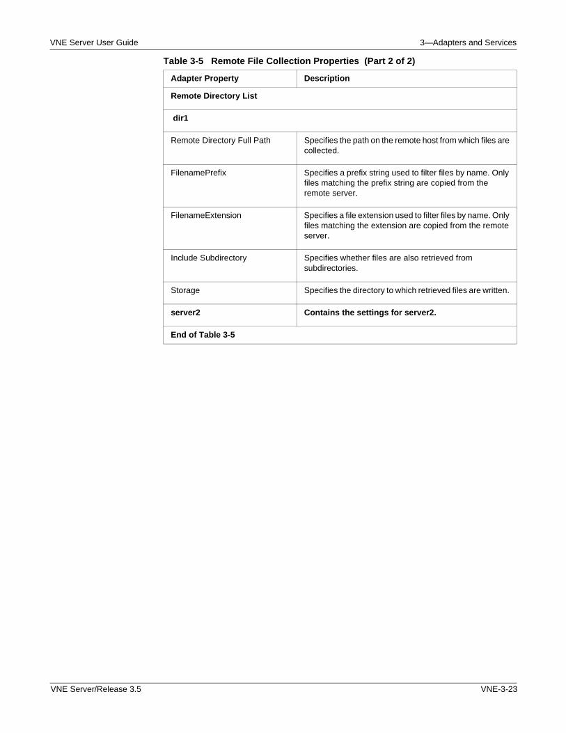
VNE Server User Guide 3—Adapters and Services
Remote Directory List
dir1
Remote Directory Full Path Specifies the path on the remote host from which files are collected.
FilenamePrefix Specifies a prefix string used to filter files by name. Only files matching the prefix string are copied from the remote server.
FilenameExtension Specifies a file extension used to filter files by name. Only files matching the extension are copied from the remote server.
Include Subdirectory Specifies whether files are also retrieved from subdirectories.
Storage Specifies the directory to which retrieved files are written.
server2 Contains the settings for server2.
End of Table 3-5
Table 3-5 Remote File Collection Properties (Part 2 of 2)
Adapter Property Description
VNE Server/Release 3.5 VNE-3-23
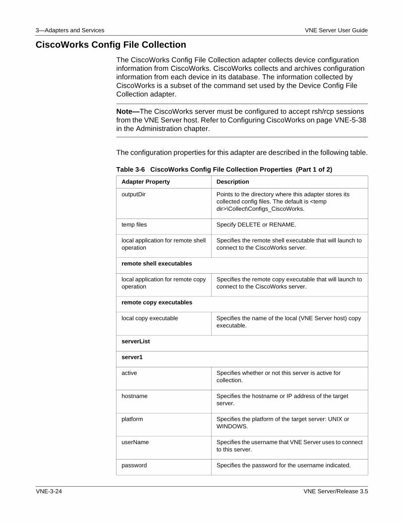
3—Adapters and Services VNE Server User Guide
CiscoWorks Config File Collection
The CiscoWorks Config File Collection adapter collects device configuration information from CiscoWorks. CiscoWorks collects and archives configuration information from each device in its database. The information collected by CiscoWorks is a subset of the command set used by the Device Config File Collection adapter.
Note—The CiscoWorks server must be configured to accept rsh/rcp sessions from the VNE Server host. Refer to Configuring CiscoWorks on page VNE-5-38 in the Administration chapter.
The configuration properties for this adapter are described in the following table.
Table 3-6 CiscoWorks Config File Collection Properties (Part 1 of 2)
Adapter Property Description
outputDir Points to the directory where this adapter stores its collected config files. The default is <temp dir>\Collect\Configs_CiscoWorks.
temp files Specify DELETE or RENAME.
local application for remote shell operation
Specifies the remote shell executable that will launch to connect to the CiscoWorks server.
remote shell executables
local application for remote copy operation
Specifies the remote copy executable that will launch to connect to the CiscoWorks server.
remote copy executables
local copy executable Specifies the name of the local (VNE Server host) copy executable.
serverList
server1
active Specifies whether or not this server is active for collection.
hostname Specifies the hostname or IP address of the target server.
platform Specifies the platform of the target server: UNIX or WINDOWS.
userName Specifies the username that VNE Server uses to connect to this server.
password Specifies the password for the username indicated.
VNE-3-24 VNE Server/Release 3.5
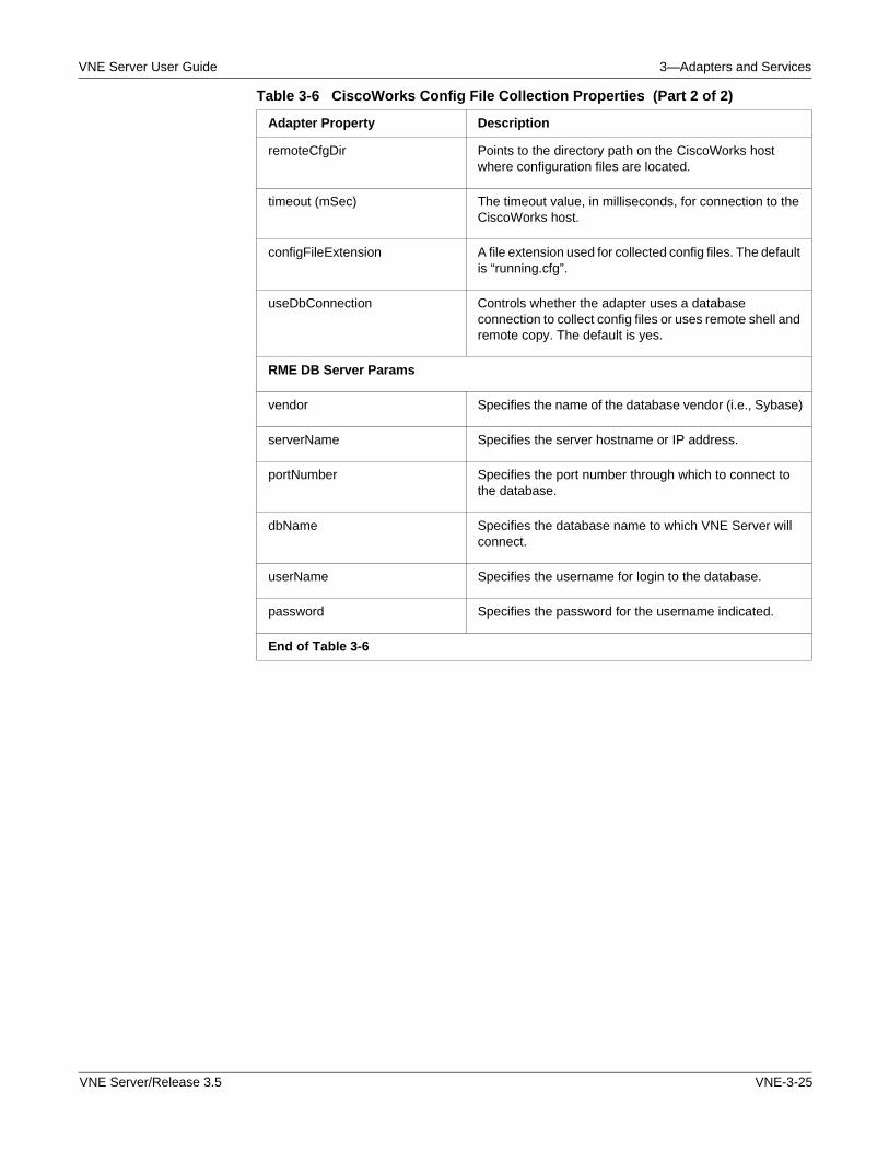
VNE Server User Guide 3—Adapters and Services
remoteCfgDir Points to the directory path on the CiscoWorks host where configuration files are located.
timeout (mSec) The timeout value, in milliseconds, for connection to the CiscoWorks host.
configFileExtension A file extension used for collected config files. The default is “running.cfg”.
useDbConnection Controls whether the adapter uses a database connection to collect config files or uses remote shell and remote copy. The default is yes.
RME DB Server Params
vendor Specifies the name of the database vendor (i.e., Sybase)
serverName Specifies the server hostname or IP address.
portNumber Specifies the port number through which to connect to the database.
dbName Specifies the database name to which VNE Server will connect.
userName Specifies the username for login to the database.
password Specifies the password for the username indicated.
End of Table 3-6
Table 3-6 CiscoWorks Config File Collection Properties (Part 2 of 2)
Adapter Property Description
VNE Server/Release 3.5 VNE-3-25
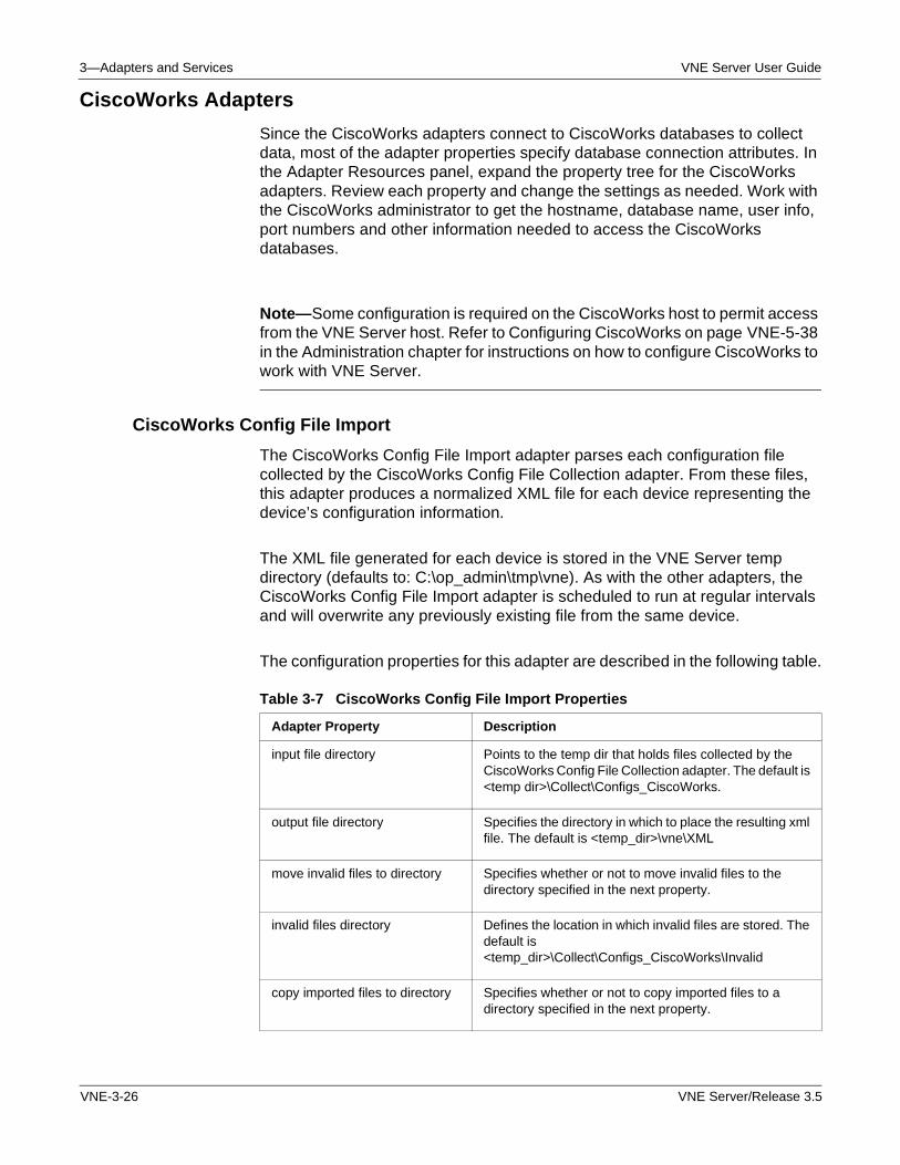
3—Adapters and Services VNE Server User Guide
CiscoWorks Adapters
Since the CiscoWorks adapters connect to CiscoWorks databases to collect data, most of the adapter properties specify database connection attributes. In the Adapter Resources panel, expand the property tree for the CiscoWorks adapters. Review each property and change the settings as needed. Work with the CiscoWorks administrator to get the hostname, database name, user info, port numbers and other information needed to access the CiscoWorks databases.
Note—Some configuration is required on the CiscoWorks host to permit access from the VNE Server host. Refer to Configuring CiscoWorks on page VNE-5-38 in the Administration chapter for instructions on how to configure CiscoWorks to work with VNE Server.
CiscoWorks Config File Import
The CiscoWorks Config File Import adapter parses each configuration file collected by the CiscoWorks Config File Collection adapter. From these files, this adapter produces a normalized XML file for each device representing the device’s configuration information.
The XML file generated for each device is stored in the VNE Server temp directory (defaults to: C:\op_admin\tmp\vne). As with the other adapters, the CiscoWorks Config File Import adapter is scheduled to run at regular intervals and will overwrite any previously existing file from the same device.
The configuration properties for this adapter are described in the following table.
Table 3-7 CiscoWorks Config File Import Properties
Adapter Property Description
input file directory Points to the temp dir that holds files collected by the CiscoWorks Config File Collection adapter. The default is <temp dir>\Collect\Configs_CiscoWorks.
output file directory Specifies the directory in which to place the resulting xml file. The default is <temp_dir>\vne\XML
move invalid files to directory Specifies whether or not to move invalid files to the directory specified in the next property.
invalid files directory Defines the location in which invalid files are stored. The default is <temp_dir>\Collect\Configs_CiscoWorks\Invalid
copy imported files to directory Specifies whether or not to copy imported files to a directory specified in the next property.
VNE-3-26 VNE Server/Release 3.5
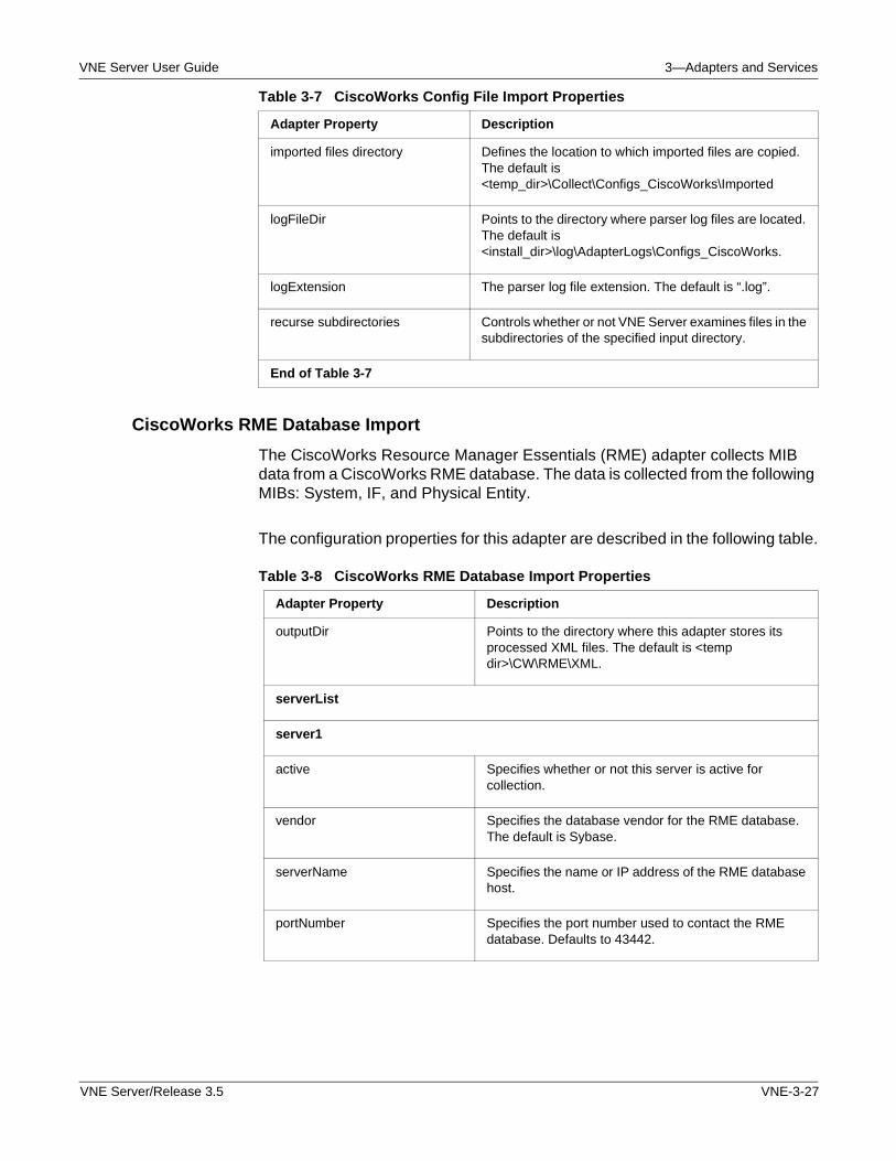
VNE Server User Guide 3—Adapters and Services
CiscoWorks RME Database Import
The CiscoWorks Resource Manager Essentials (RME) adapter collects MIB data from a CiscoWorks RME database. The data is collected from the following MIBs: System, IF, and Physical Entity.
The configuration properties for this adapter are described in the following table.
imported files directory Defines the location to which imported files are copied. The default is <temp_dir>\Collect\Configs_CiscoWorks\Imported
logFileDir Points to the directory where parser log files are located. The default is <install_dir>\log\AdapterLogs\Configs_CiscoWorks.
logExtension The parser log file extension. The default is “.log”.
recurse subdirectories Controls whether or not VNE Server examines files in the subdirectories of the specified input directory.
End of Table 3-7
Table 3-7 CiscoWorks Config File Import Properties
Adapter Property Description
Table 3-8 CiscoWorks RME Database Import Properties
Adapter Property Description
outputDir Points to the directory where this adapter stores its processed XML files. The default is <temp dir>\CW\RME\XML.
serverList
server1
active Specifies whether or not this server is active for collection.
vendor Specifies the database vendor for the RME database. The default is Sybase.
serverName Specifies the name or IP address of the RME database host.
portNumber Specifies the port number used to contact the RME database. Defaults to 43442.
VNE Server/Release 3.5 VNE-3-27
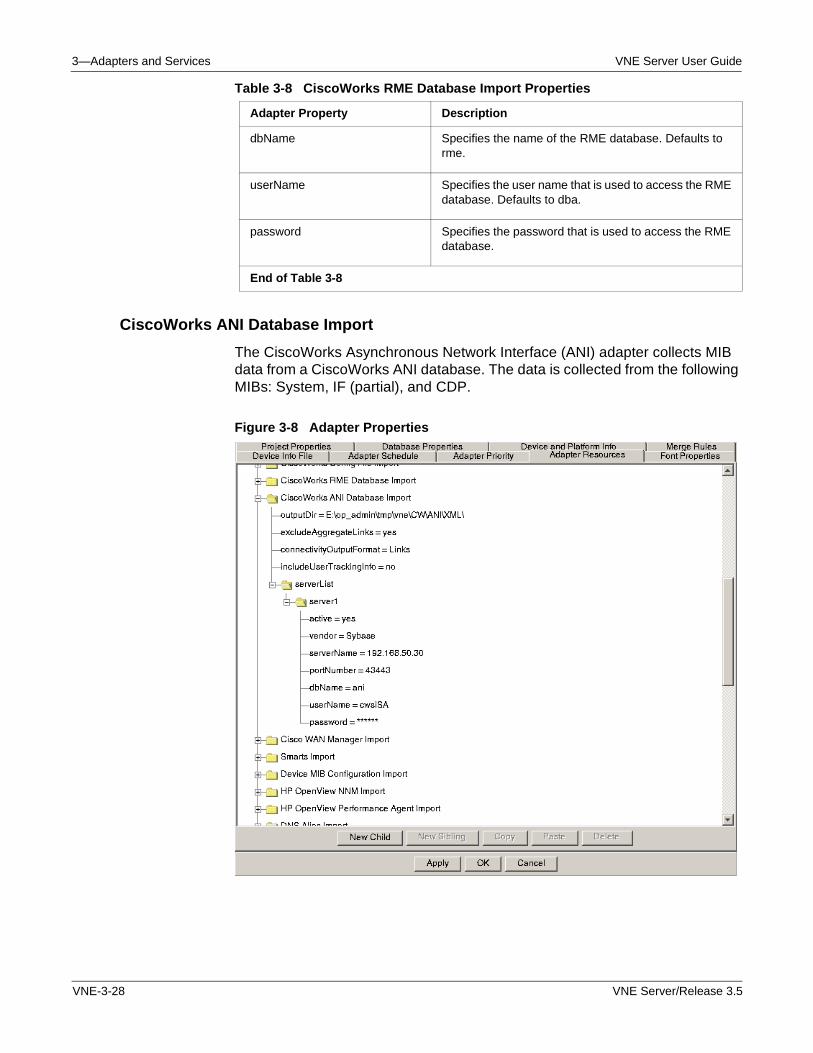
3—Adapters and Services VNE Server User Guide
CiscoWorks ANI Database Import
The CiscoWorks Asynchronous Network Interface (ANI) adapter collects MIB data from a CiscoWorks ANI database. The data is collected from the following MIBs: System, IF (partial), and CDP.
Figure 3-8 Adapter Properties
dbName Specifies the name of the RME database. Defaults to rme.
userName Specifies the user name that is used to access the RME database. Defaults to dba.
password Specifies the password that is used to access the RME database.
End of Table 3-8
Table 3-8 CiscoWorks RME Database Import Properties
Adapter Property Description
VNE-3-28 VNE Server/Release 3.5
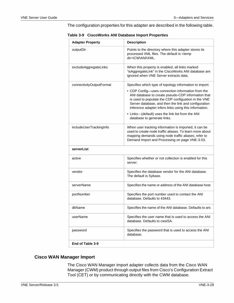
VNE Server User Guide 3—Adapters and Services
The configuration properties for this adapter are described in the following table.
Cisco WAN Manager Import
The Cisco WAN Manager import adapter collects data from the Cisco WAN Manager (CWM) product through output files from Cisco’s Configuration Extract Tool (CET) or by communicating directly with the CWM database.
Table 3-9 CiscoWorks ANI Database Import Properties
Adapter Property Description
outputDir Points to the directory where this adapter stores its processed XML files. The default is <temp dir>\CW\ANI\XML.
excludeAggregateLinks When this property is enabled, all links marked “isAggregateLink” in the CiscoWorks ANI database are ignored when VNE Server extracts data.
connectivityOutputFormat Specifies which type of topology information to import:
• CDP Config—uses connection information from the ANI database to create pseudo-CDP information that is used to populate the CDP configuation in the VNE Server database, and then the link and configuration inference adapter infers links using this information.
• Links—(default) uses the link list from the ANI database to generate links.
includeUserTrackingInfo When user tracking information is imported, it can be used to create node traffic aliases. To learn more about mapping demands using node traffic aliases, refer to Demand Import and Processing on page VNE-3-53.
serverList
active Specifies whether or not collection is enabled for this server.
vendor Specifies the database vendor for the ANI database. The default is Sybase.
serverName Specifies the name or address of the ANI database host.
portNumber Specifies the port number used to contact the ANI database. Defaults to 43443.
dbName Specifies the name of the ANI database. Defaults to ani.
userName Specifies the user name that is used to access the ANI database. Defaults to cwsiSA.
password Specifies the password that is used to access the ANI database.
End of Table 3-9
VNE Server/Release 3.5 VNE-3-29
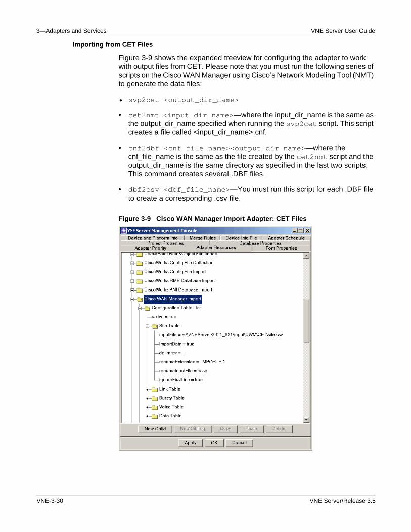
3—Adapters and Services VNE Server User Guide
Importing from CET Files
Figure 3-9 shows the expanded treeview for configuring the adapter to work with output files from CET. Please note that you must run the following series of scripts on the Cisco WAN Manager using Cisco’s Network Modeling Tool (NMT) to generate the data files:
• svp2cet <output_dir_name>
• cet2nmt <input_dir_name>—where the input_dir_name is the same as the output_dir_name specified when running the svp2cet script. This script creates a file called <input_dir_name>.cnf.
• cnf2dbf <cnf_file_name><output_dir_name>—where the cnf_file_name is the same as the file created by the cet2nmt script and the output_dir_name is the same directory as specified in the last two scripts. This command creates several .DBF files.
• dbf2csv <dbf_file_name>—You must run this script for each .DBF file to create a corresponding .csv file.
Figure 3-9 Cisco WAN Manager Import Adapter: CET Files
VNE-3-30 VNE Server/Release 3.5
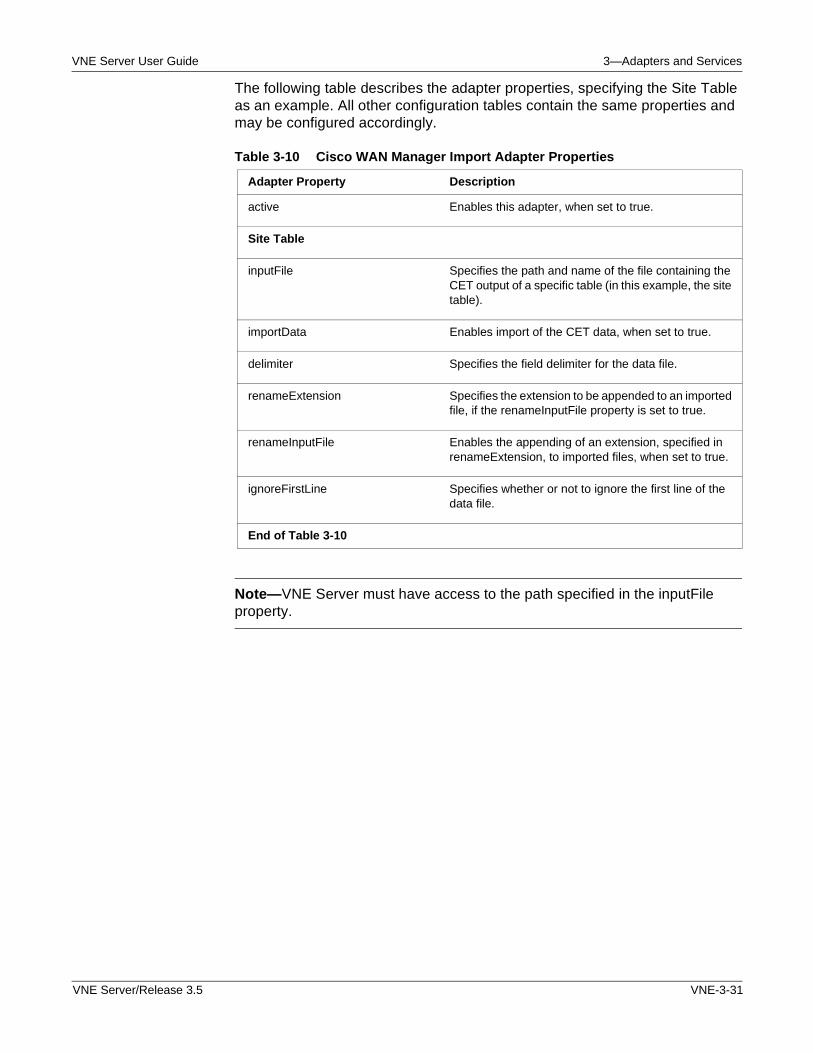
VNE Server User Guide 3—Adapters and Services
The following table describes the adapter properties, specifying the Site Table as an example. All other configuration tables contain the same properties and may be configured accordingly.
Note—VNE Server must have access to the path specified in the inputFile property.
Table 3-10 Cisco WAN Manager Import Adapter Properties
Adapter Property Description
active Enables this adapter, when set to true.
Site Table
inputFile Specifies the path and name of the file containing the CET output of a specific table (in this example, the site table).
importData Enables import of the CET data, when set to true.
delimiter Specifies the field delimiter for the data file.
renameExtension Specifies the extension to be appended to an imported file, if the renameInputFile property is set to true.
renameInputFile Enables the appending of an extension, specified in renameExtension, to imported files, when set to true.
ignoreFirstLine Specifies whether or not to ignore the first line of the data file.
End of Table 3-10
VNE Server/Release 3.5 VNE-3-31
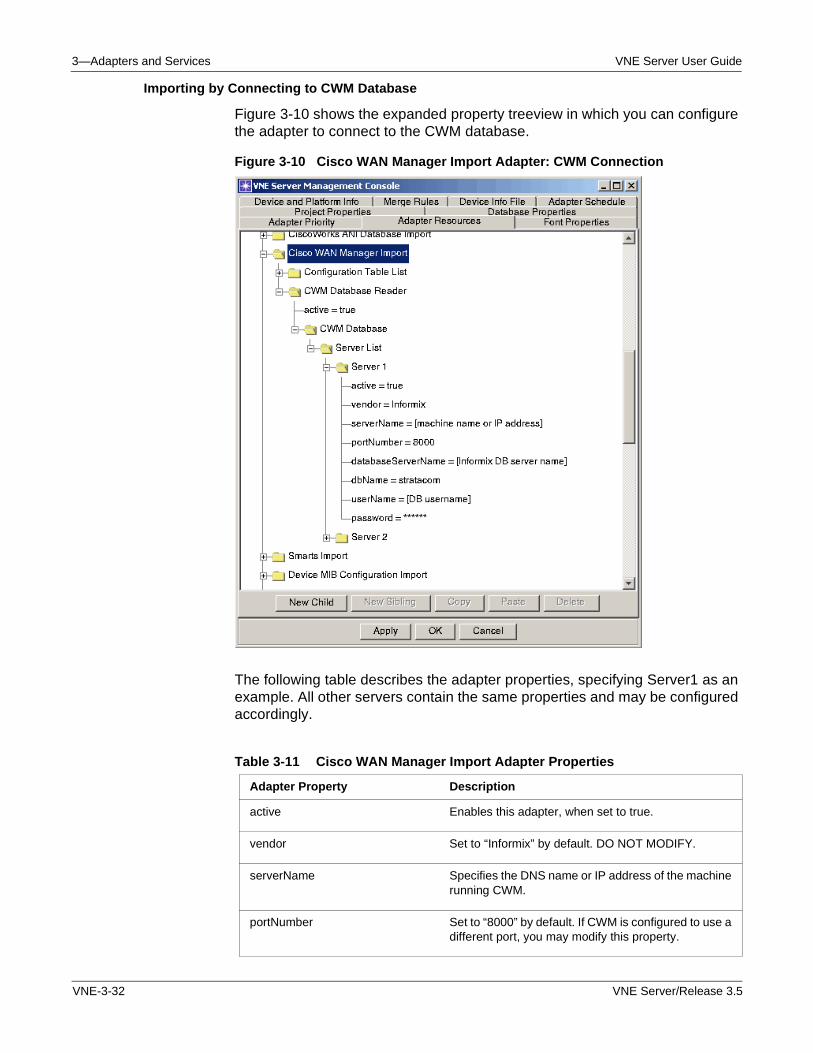
3—Adapters and Services VNE Server User Guide
Importing by Connecting to CWM Database
Figure 3-10 shows the expanded property treeview in which you can configure the adapter to connect to the CWM database.
Figure 3-10 Cisco WAN Manager Import Adapter: CWM Connection
The following table describes the adapter properties, specifying Server1 as an example. All other servers contain the same properties and may be configured accordingly.
Table 3-11 Cisco WAN Manager Import Adapter Properties
Adapter Property Description
active Enables this adapter, when set to true.
vendor Set to “Informix” by default. DO NOT MODIFY.
serverName Specifies the DNS name or IP address of the machine running CWM.
portNumber Set to “8000” by default. If CWM is configured to use a different port, you may modify this property.
VNE-3-32 VNE Server/Release 3.5
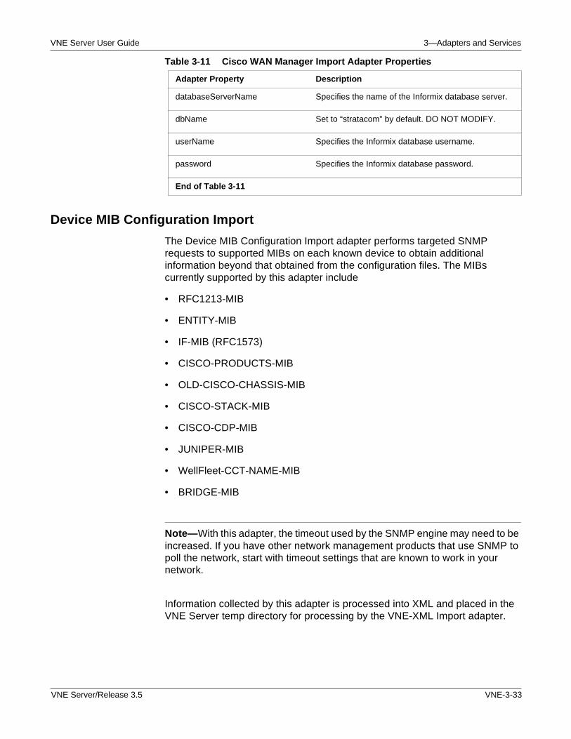
VNE Server User Guide 3—Adapters and Services
Device MIB Configuration Import
The Device MIB Configuration Import adapter performs targeted SNMP requests to supported MIBs on each known device to obtain additional information beyond that obtained from the configuration files. The MIBs currently supported by this adapter include
• RFC1213-MIB
• ENTITY-MIB
• IF-MIB (RFC1573)
• CISCO-PRODUCTS-MIB
• OLD-CISCO-CHASSIS-MIB
• CISCO-STACK-MIB
• CISCO-CDP-MIB
• JUNIPER-MIB
• WellFleet-CCT-NAME-MIB
• BRIDGE-MIB
Note—With this adapter, the timeout used by the SNMP engine may need to be increased. If you have other network management products that use SNMP to poll the network, start with timeout settings that are known to work in your network.
Information collected by this adapter is processed into XML and placed in the VNE Server temp directory for processing by the VNE-XML Import adapter.
databaseServerName Specifies the name of the Informix database server.
dbName Set to “stratacom” by default. DO NOT MODIFY.
userName Specifies the Informix database username.
password Specifies the Informix database password.
End of Table 3-11
Table 3-11 Cisco WAN Manager Import Adapter Properties
Adapter Property Description
VNE Server/Release 3.5 VNE-3-33
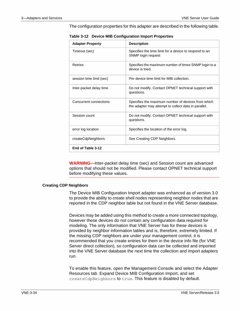
3—Adapters and Services VNE Server User Guide
The configuration properties for this adapter are described in the following table.
WARNING—Inter-packet delay time (sec) and Session count are advanced options that should not be modified. Please contact OPNET technical support before modifying these values.
Creating CDP Neighbors
The Device MIB Configuration Import adapter was enhanced as of version 3.0 to provide the ability to create shell nodes representing neighbor nodes that are reported in the CDP neighbor table but not found in the VNE Server database.
Devices may be added using this method to create a more connected topology, however these devices do not contain any configuration data required for modeling. The only information that VNE Server has for these devices is provided by neighbor information tables and is, therefore, extremely limited. If the missing CDP neighbors are under your management control, it is recommended that you create entries for them in the device info file (for VNE Server direct collection), so configuration data can be collected and imported into the VNE Server database the next time the collection and import adapters run.
To enable this feature, open the Management Console and select the Adapter Resources tab. Expand Device MIB Configuration Import, and set createCdpNeighbors to true. This feature is disabled by default.
Table 3-12 Device MIB Configuration Import Properties
Adapter Property Description
Timeout (sec) Specifies the time limit for a device to respond to an SNMP login request
Retries Specifies the maximum number of times SNMP login to a device is tried.
session time limit (sec) Per device time limit for MIB collection.
Inter-packet delay time Do not modify. Contact OPNET technical support with questions.
Concurrent connections Specifies the maximum number of devices from which the adapter may attempt to collect data in parallel.
Session count Do not modify. Contact OPNET technical support with questions.
error log location Specifies the location of the error log.
createCdpNeighbors See Creating CDP Neighbors.
End of Table 3-12
VNE-3-34 VNE Server/Release 3.5
VNE Server User Guide 3—Adapters and Services
Support for SNMPv3
Device MIB Configuration Import and MIB Interface Utilization Import adapters provide support for SNMPv3. The following parameters are included in the Device Info file:
• SNMP v3 User Name
• SNMP v3 Context ID
• SNMP v3 Context Name
• SNMP v3 Authentication Protocol
• SNMP v3 Security Level
• SNMP v3 Authentication Password
• SNMP v3 Privacy Protocol
• SNMP v3 Privacy Password
When SNMP v3 User Name, Context ID, or Context Name is supplied in the device and platform info tab of the Management Console and Collect MIB is active for the device, the Device MIB Configuration Import adapter will first try to use SNMPv3 to collect MIB data from the device. If no data is collected, this adapter will attempt to collect using earlier versions of SNMP (v2c, v2, v1), however, the community string must be supplied in order for MIB collection to be successful using earlier versions of SNMP.
VNE Server/Release 3.5 VNE-3-35
3—Adapters and Services VNE Server User Guide
HP OpenView NNM Import
The HP OpenView Network Node Manager (NNM) Import adapter collects device and topology information from HP OpenView. The information collected includes System group and IF MIB data. This adapter provides devices links and connections to VNE Server. The HP OpenView NNM adapter uses the ovdb application programming interface to connect and retrieve data from HP OpenView. For this adapter, change the HP OpenView access properties to match those used in your network.
Note—If VNE Server is located on a different host machine than HP OpenView, some configuration is required in the HP OpenView environment to permit access from the VNE Server host. Refer to Configuring HP OpenView on page VNE-5-37 in the Administration chapter for instructions on how to configure HP OpenView to work with VNE Server.
Note—The HP OpenView NNM server must be configured to allow access to VNE Server. Refer to Configuring HP OpenView on page VNE-5-37 in the Administration chapter.
Note—When connecting to HP OpenView NNM version 6.2, or later, set the dbPort number property to 2447. If the HP OpenView NNM version is 6.1, use 9999 for the dbPort number.
The configuration properties for this adapter are described in the following table.
Table 3-13 HP OpenView NNM Import Properties
Adapter Property Description
outputDir Points to the directory where this adapter stores its collected files. The default is <temp dir>\hpov.
serverList
server1
active Specifies whether or not this server is active for collection.
VNE-3-36 VNE Server/Release 3.5
VNE Server User Guide 3—Adapters and Services
DNS Alias Import
The DNS Alias Import adapter performs a reverse DNS lookup on IP interfaces in the database. For any matches found, the DNS alias is saved in the network model. This adapter can be thought of as a utility adapter. It collects information that can aid other adapters in doing interface and node level matching required in order to import their data into the network model. Contact OPNET for advice on whether you need to use this adapter based upon the adapter mix you plan to use to build your network model.
Link and Connection Inference Service
The properties for Link and Connection Inference Service allow you to disable link inference based upon a specific information source. Link creation based upon ARP and CAM data is disabled by default. Consider whether you should enable these properties.
hostName Specifies the name or address of the HP OpenView host.
dbUser Specifies the user name that is used to access the HP OpenView database. Defaults to ovdb.
dbPort Specifies the port number used to contact the HP OpenView database. Defaults to 2447.
End of Table 3-13
Table 3-13 HP OpenView NNM Import Properties
Adapter Property Description
VNE Server/Release 3.5 VNE-3-37
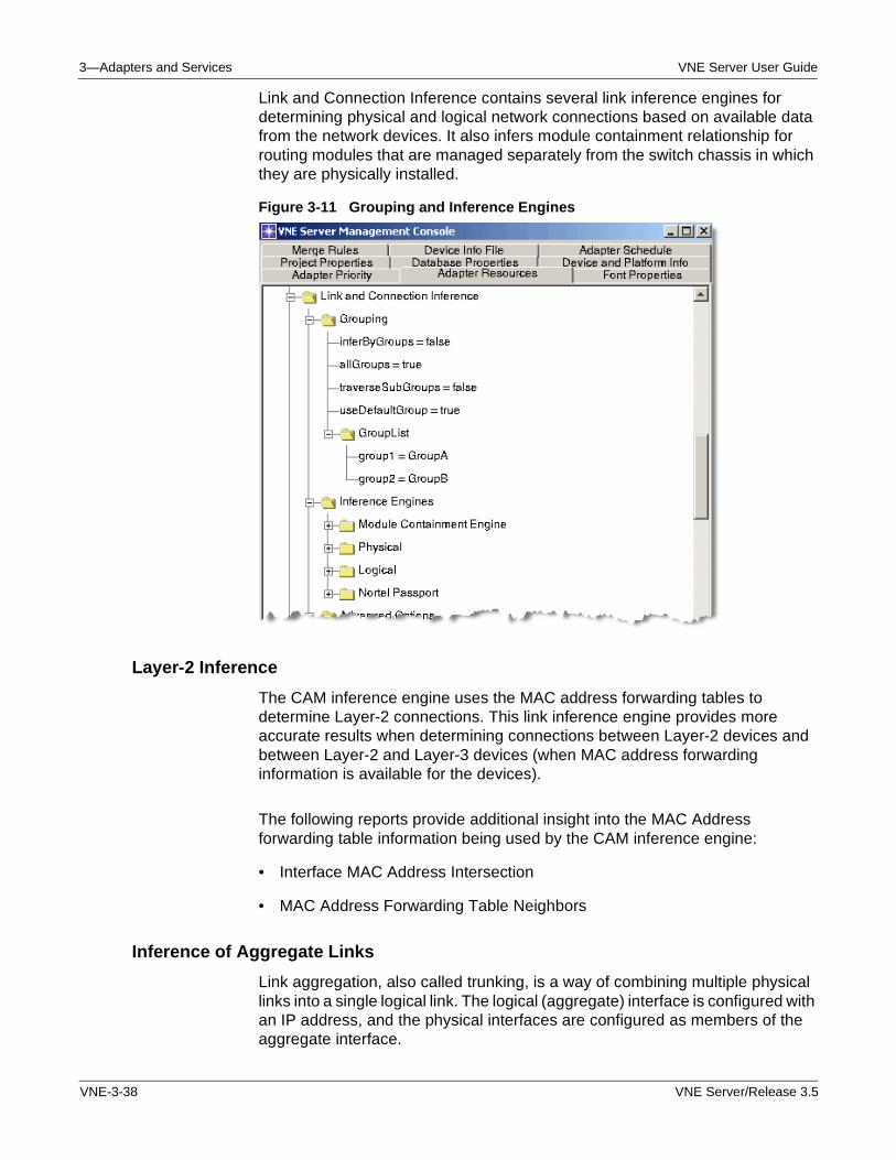
3—Adapters and Services VNE Server User Guide
Link and Connection Inference contains several link inference engines for determining physical and logical network connections based on available data from the network devices. It also infers module containment relationship for routing modules that are managed separately from the switch chassis in which they are physically installed.
Figure 3-11 Grouping and Inference Engines
Layer-2 Inference
The CAM inference engine uses the MAC address forwarding tables to determine Layer-2 connections. This link inference engine provides more accurate results when determining connections between Layer-2 devices and between Layer-2 and Layer-3 devices (when MAC address forwarding information is available for the devices).
The following reports provide additional insight into the MAC Address forwarding table information being used by the CAM inference engine:
• Interface MAC Address Intersection
• MAC Address Forwarding Table Neighbors
Inference of Aggregate Links
Link aggregation, also called trunking, is a way of combining multiple physical links into a single logical link. The logical (aggregate) interface is configured with an IP address, and the physical interfaces are configured as members of the aggregate interface.
VNE-3-38 VNE Server/Release 3.5
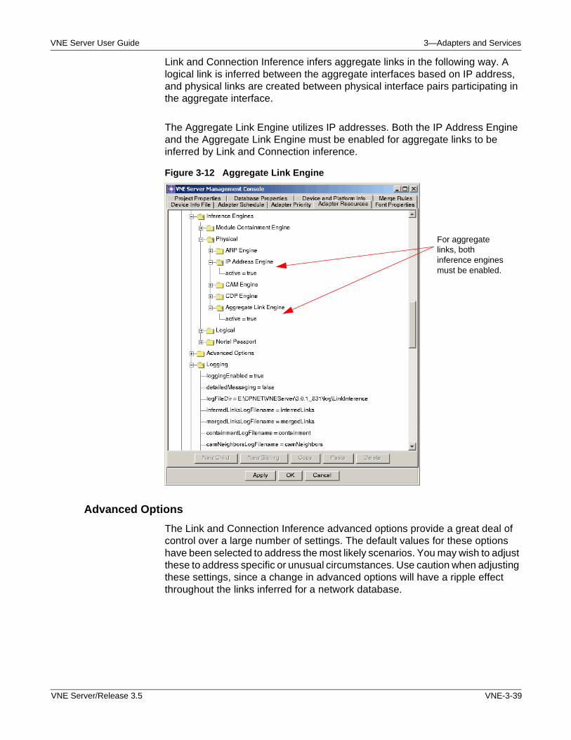
VNE Server User Guide 3—Adapters and Services
Link and Connection Inference infers aggregate links in the following way. A logical link is inferred between the aggregate interfaces based on IP address, and physical links are created between physical interface pairs participating in the aggregate interface.
The Aggregate Link Engine utilizes IP addresses. Both the IP Address Engine and the Aggregate Link Engine must be enabled for aggregate links to be inferred by Link and Connection inference.
Figure 3-12 Aggregate Link Engine
Advanced Options
The Link and Connection Inference advanced options provide a great deal of control over a large number of settings. The default values for these options have been selected to address the most likely scenarios. You may wish to adjust these to address specific or unusual circumstances. Use caution when adjusting these settings, since a change in advanced options will have a ripple effect throughout the links inferred for a network database.
For aggregate links, both inference engines must be enabled.
VNE Server/Release 3.5 VNE-3-39
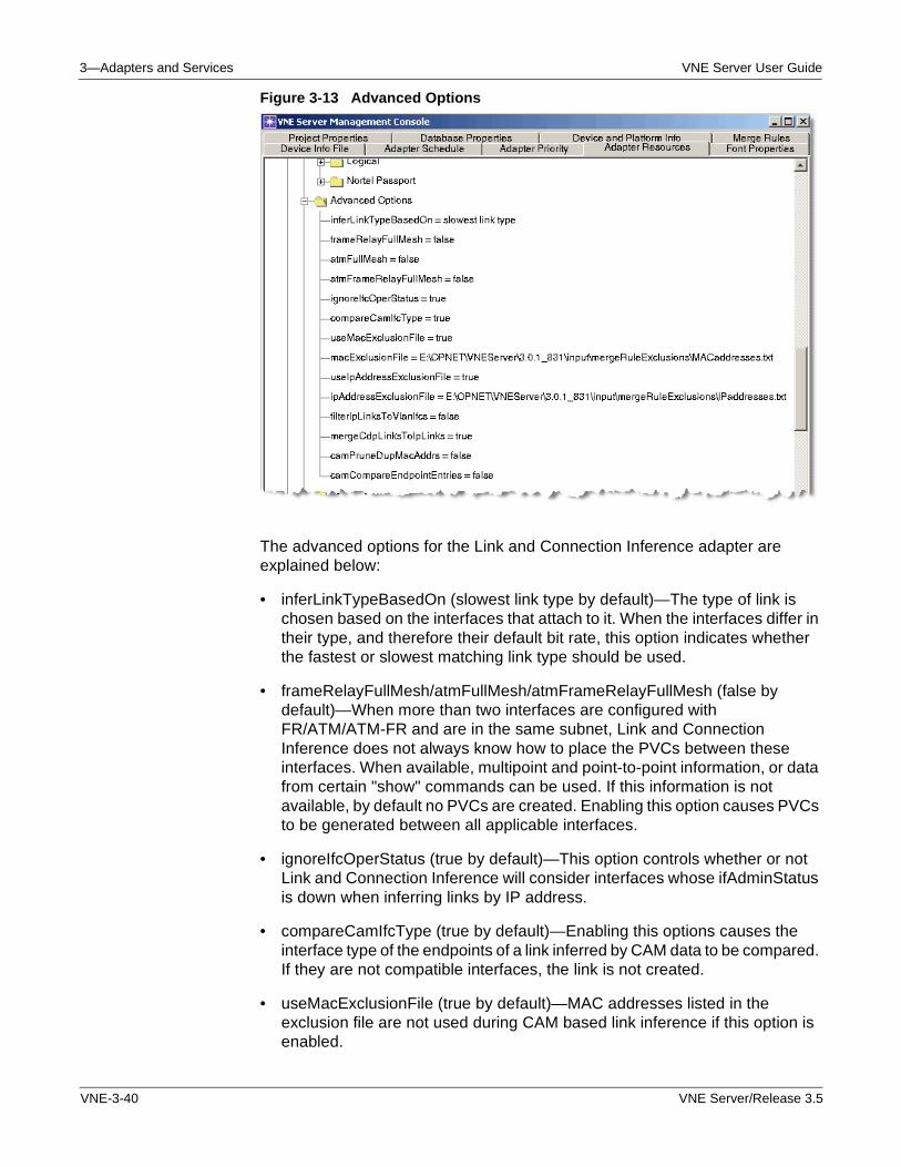
3—Adapters and Services VNE Server User Guide
Figure 3-13 Advanced Options
The advanced options for the Link and Connection Inference adapter are explained below:
• inferLinkTypeBasedOn (slowest link type by default)—The type of link is chosen based on the interfaces that attach to it. When the interfaces differ in their type, and therefore their default bit rate, this option indicates whether the fastest or slowest matching link type should be used.
• frameRelayFullMesh/atmFullMesh/atmFrameRelayFullMesh (false by default)—When more than two interfaces are configured with FR/ATM/ATM-FR and are in the same subnet, Link and Connection Inference does not always know how to place the PVCs between these interfaces. When available, multipoint and point-to-point information, or data from certain "show" commands can be used. If this information is not available, by default no PVCs are created. Enabling this option causes PVCs to be generated between all applicable interfaces.
• ignoreIfcOperStatus (true by default)—This option controls whether or not Link and Connection Inference will consider interfaces whose ifAdminStatus is down when inferring links by IP address.
• compareCamIfcType (true by default)—Enabling this options causes the interface type of the endpoints of a link inferred by CAM data to be compared. If they are not compatible interfaces, the link is not created.
• useMacExclusionFile (true by default)—MAC addresses listed in the exclusion file are not used during CAM based link inference if this option is enabled.
VNE-3-40 VNE Server/Release 3.5
VNE Server User Guide 3—Adapters and Services
• macExclusionFile—Identifies the location of the MAC address exclusion file.
• useIpAddressExclusionFile (true by default)—IP addresses listed in the exclusion file are not used during IP address based link inference, if this option is enabled.
• ipAddressExclusionFile—Identifies the location of the MAC address exclusion file.
• filterIpLinksToVlanIfcs (false by default)—Enabling this option will cause IP address-based links to be removed, if they terminate on a VLAN interface. This option would be enabled in networks where we have sufficient data (CDP/EDP and CAM) for determining the layer-2 portion of the topology.
• mergeCdpLinksToIpLinks (true by default)—Normally, each inference engine overwrites the links inferred by previous engines. Enabling this option causes CDP-based inferred links to merge into links inferred by IP address rather than overwriting them. This option is useful in cases where neighbor discovery data is incomplete due to it not being enabled on all devices/interfaces.
• camPruneDupMacAddrs (false by default)—In networks that have switches who report the same MAC address for multiple interfaces, it is not always possible to determine which interface should by used as a link endpoint during CAM-based link inference. This is because the remote MAC address, pointed to in the source switch's CAM table, cannot be resolved to a single interface. When this attribute is enabled, if more than one interface on a device reports the same MAC address, VNE Server narrows that list of interfaces to a single interface using the following rules for each interface sharing that common MAC address:
— First, pick the interfaces that have a CAM entry pointing back to the source interface
— Next, choose the interface of the remaining interfaces that has the most CAM entries (most active interface)
— Finally, if there was a tie from the previous rule, choose the interface whose name is lexicographically shorter.
• camCompareEndpointEntries (false by default)—This option forces a link to be visible in both directions. In other words, both switch interface endpoints have CAM data that specifies the same link in each direction.
Trace Route Link Inference Service
The Trace Route Link Inference Service is a lowest common denominator means of determining connectivity and intervening Layer-3 devices between network devices that already exist in the model. This service provides a convenient, automated means of ensuring that your network model is complete from a connectivity standpoint.
VNE Server/Release 3.5 VNE-3-41
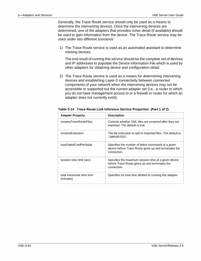
3—Adapters and Services VNE Server User Guide
Generally, the Trace Route service should only be used as a means to determine the intervening devices. Once the intervening devices are determined, one of the adapters that provides richer detail (if available) should be used to gain information from the device. The Trace Route service may be used under two different scenarios:
1) The Trace Route service is used as an automated assistant to determine missing devices.
The end result of running this service should be the complete set of devices and IP addresses to populate the Device Information File which is used by other adapters for obtaining device and configuration detail.
2) The Trace Route service is used as a means for determining intervening devices and establishing Layer-3 connectivity between connected components of your network when the intervening devices may not be accessible or supported but the current adapter set (i.e., a router to which you do not have management access to or a firewall or router for which an adapter does not currently exist).
Table 3-14 Trace Route Link Inference Service Properties (Part 1 of 2)
Adapter Property Description
renameTraceRouteFiles Controls whether XML files are renamed after they are imported. The default is true.
renameExtension The file extension to add to imported files. The default is “.IMPORTED”.
maxFailedCmdPerNode Specifies the number of failed commands at a given device before Trace Route gives up and terminates the connection.
session time limit (sec) Specifies the maximum session time at a given device before Trace Route gives up and terminates the connection.
total traceroute time limit (minutes)
Specifies he total time allotted to running this adapter.
VNE-3-42 VNE Server/Release 3.5
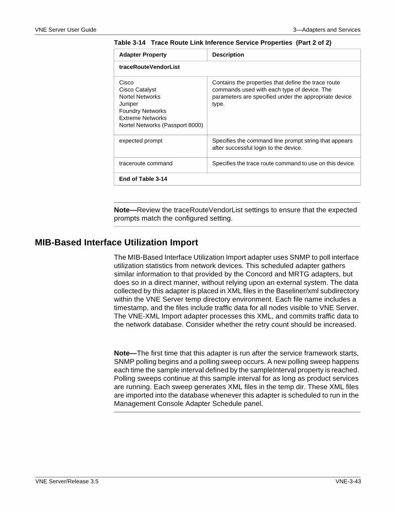
VNE Server User Guide 3—Adapters and Services
Note—Review the traceRouteVendorList settings to ensure that the expected prompts match the configured setting.
MIB-Based Interface Utilization Import
The MIB-Based Interface Utilization Import adapter uses SNMP to poll interface utilization statistics from network devices. This scheduled adapter gathers similar information to that provided by the Concord and MRTG adapters, but does so in a direct manner, without relying upon an external system. The data collected by this adapter is placed in XML files in the Baseliner/xml subdirectory within the VNE Server temp directory environment. Each file name includes a timestamp, and the files include traffic data for all nodes visible to VNE Server. The VNE-XML Import adapter processes this XML, and commits traffic data to the network database. Consider whether the retry count should be increased.
Note—The first time that this adapter is run after the service framework starts, SNMP polling begins and a polling sweep occurs. A new polling sweep happens each time the sample interval defined by the sampleInterval property is reached. Polling sweeps continue at this sample interval for as long as product services are running. Each sweep generates XML files in the temp dir. These XML files are imported into the database whenever this adapter is scheduled to run in the Management Console Adapter Schedule panel.
traceRouteVendorList
CiscoCisco CatalystNortel NetworksJuniperFoundry NetworksExtreme NetworksNortel Networks (Passport 8000)
Contains the properties that define the trace route commands used with each type of device. The parameters are specified under the appropriate device type.
expected prompt Specifies the command line prompt string that appears after successful login to the device.
traceroute command Specifies the trace route command to use on this device.
End of Table 3-14
Table 3-14 Trace Route Link Inference Service Properties (Part 2 of 2)
Adapter Property Description
VNE Server/Release 3.5 VNE-3-43
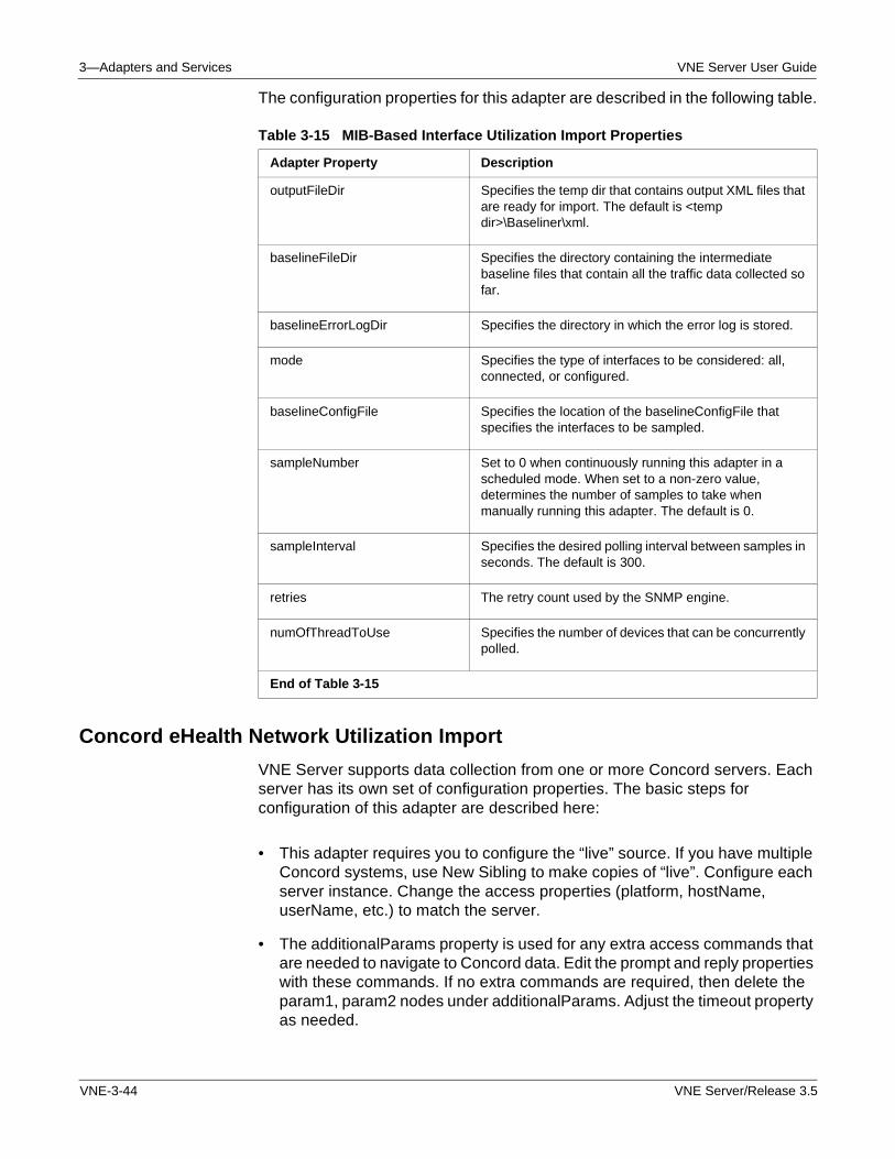
3—Adapters and Services VNE Server User Guide
The configuration properties for this adapter are described in the following table.
Concord eHealth Network Utilization Import
VNE Server supports data collection from one or more Concord servers. Each server has its own set of configuration properties. The basic steps for configuration of this adapter are described here:
• This adapter requires you to configure the “live” source. If you have multiple Concord systems, use New Sibling to make copies of “live”. Configure each server instance. Change the access properties (platform, hostName, userName, etc.) to match the server.
• The additionalParams property is used for any extra access commands that are needed to navigate to Concord data. Edit the prompt and reply properties with these commands. If no extra commands are required, then delete the param1, param2 nodes under additionalParams. Adjust the timeout property as needed.
Table 3-15 MIB-Based Interface Utilization Import Properties
Adapter Property Description
outputFileDir Specifies the temp dir that contains output XML files that are ready for import. The default is <temp dir>\Baseliner\xml.
baselineFileDir Specifies the directory containing the intermediate baseline files that contain all the traffic data collected so far.
baselineErrorLogDir Specifies the directory in which the error log is stored.
mode Specifies the type of interfaces to be considered: all, connected, or configured.
baselineConfigFile Specifies the location of the baselineConfigFile that specifies the interfaces to be sampled.
sampleNumber Set to 0 when continuously running this adapter in a scheduled mode. When set to a non-zero value, determines the number of samples to take when manually running this adapter. The default is 0.
sampleInterval Specifies the desired polling interval between samples in seconds. The default is 300.
retries The retry count used by the SNMP engine.
numOfThreadToUse Specifies the number of devices that can be concurrently polled.
End of Table 3-15
VNE-3-44 VNE Server/Release 3.5
VNE Server User Guide 3—Adapters and Services
• Change the commandPrompt property to reflect the command line prompt displayed by the Concord host.
• Expand the cnhExport property tree. Adjust the timeout property as needed. Change trafficRange to the setting that reflects the amount of traffic to import from Concord.
• Expand the groupNames property. Add, change or remove groups to match those setup on the Concord server.
• Set the active property to yes. Configuration is complete.
Refer to Configuring Concord eHealth on page VNE-5-41 in the Administration chapter for more information about how to configure Concord to work with VNE Server.
The Concord eHealth Network Utilization Import adapter imports interface utilization statistics collected from one or more Concord systems. VNE Server uses telnet to connect to the Concord system. Once connected, Concord commands are issued to display the traffic group data specified by the adapter properties. The output of the traffic report commands is saved in the adapter temp directory as dci and ddo files. Each traffic group specified in the adapter properties produces a timestamped dci/ddo file pair after a Concord collection session. The dci files contain setup information about the interfaces in each traffic group. The ddo files contain the interface utilization statistics for each interface in the traffic group. The dci/ddo files are saved in the VNE Server temp cnh/input subdirectory.
The Concord adapter processes the dci/ddo files for each traffic group. The adapter converts the traffic data for each device into timestamped XML files in the cnh/xml subdirectory. Each device has an XML file that contains traffic data for its interfaces. These files are imported by the VNE-XML Import adapter.
To configure this adapter, set up the Concord login properties, and modify the groupNames list to contain the names of the traffic groups you wish to collect. Work with the Concord administrator to determine the traffic groups you need. If you have more than one Concord system, clone and configure the “live” property tree for each system.
VNE Server/Release 3.5 VNE-3-45
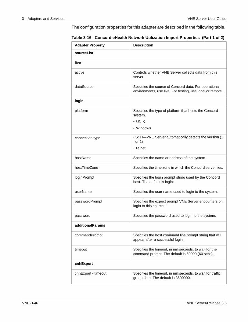
3—Adapters and Services VNE Server User Guide
The configuration properties for this adapter are described in the following table.
Table 3-16 Concord eHealth Network Utilization Import Properties (Part 1 of 2)
Adapter Property Description
sourceList
live
active Controls whether VNE Server collects data from this server.
dataSource Specifies the source of Concord data. For operational environments, use live. For testing, use local or remote.
login
platform Specifies the type of platform that hosts the Concord system.
• UNIX
• Windows
connection type • SSH—VNE Server automatically detects the version (1 or 2)
• Telnet
hostName Specifies the name or address of the system.
hostTimeZone Specifies the time zone in which the Concord server lies.
loginPrompt Specifies the login prompt string used by the Concord host. The default is login:
userName Specifies the user name used to login to the system.
passwordPrompt Specifies the expect prompt VNE Server encounters on login to this source.
password Specifies the password used to login to the system.
additionalParams
commandPrompt Specifies the host command line prompt string that will appear after a successful login.
timeout Specifies the timeout, in milliseconds, to wait for the command prompt. The default is 60000 (60 secs).
cnhExport
cnhExport - timeout Specifies the timeout, in milliseconds, to wait for traffic group data. The default is 3600000.
VNE-3-46 VNE Server/Release 3.5
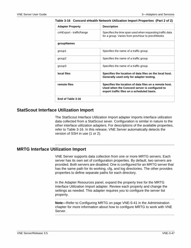
VNE Server User Guide 3—Adapters and Services
StatScout Interface Utilization Import
The StatScout Interface Utilization Import adapter imports interface utilization data collected from a StatScout sever. Configuration is similar in nature to the other interface utilization adapters. For descriptions of the available properties, refer to Table 3-16. In this release, VNE Server automatically detects the version of SSH in use (1 or 2).
MRTG Interface Utilization Import
VNE Server supports data collection from one or more MRTG servers. Each server has its own set of configuration properties. By default, two servers are provided. Both servers are disabled. One is configured for an MRTG server that has the same path for its working, cfg, and log directories. The other provides properties to define separate paths for each directory.
In the Adapter Resources panel, expand the property tree for the MRTG Interface Utilization Import adapter. Review each property and change the settings as needed. This adapter requires you to configure the server list property.
Note—Refer to Configuring MRTG on page VNE-5-41 in the Administration chapter for more information about how to configure MRTG to work with VNE Server.
cnhExport - trafficRange Specifies the time span used when requesting traffic data for a group. Varies from prevHour to prev4Weeks
groupNames
group1 Specifies the name of a traffic group.
group2 Specifies the name of a traffic group.
group3 Specifies the name of a traffic group.
local files Specifies the location of data files on the local host. Generally used only for adapter testing.
remote files Specifies the location of data files on a remote host. Used when the Concord server is configured to export traffic files on a scheduled basis.
End of Table 3-16
Table 3-16 Concord eHealth Network Utilization Import Properties (Part 2 of 2)
Adapter Property Description
VNE Server/Release 3.5 VNE-3-47
3—Adapters and Services VNE Server User Guide
Note the following:
• If you have one MRTG server, and its working directory configuration matches one of the default servers, edit the access properties (hostName, userName, etc.) for the matching server entry. Set the working directory paths. Set the active property to yes. Configuration is complete.
• If neither MRTG server entry matches your server setup, alter the closest setup by adding and changing properties until you are done. Configure the access properties, set the working directory paths and set the active property to yes.
• If one of the existing MRTG servers matches your server setup, but you have more than one server with this setup, then use the New Sibling button to clone the matching setup for each of server. Configure the access properties, set the working directory paths and set the active property to yes for each server.
This release of the adapter provides better compatibility with Windows FTP servers. On a Windows FTP server, the FTP file path is relative to the FTP server's root directory. The user specifies the FTP root directory on the FTP server so that VNE Server can resolve the MS-DOS path to the FTP file path. This attribute is configured in MRTG Interface Utilization Import > mrtgServerList > Regular MRTG Server > ftp > ftpRootDir or MRTG Interface Utilization Import > mrtgServerList > RRD Integrated MRTG Server > ftp > ftpRootDir.
Note—For additional information on how to configure the MRTG Interface Utilization adapter to work with a Windows IIS FTP Server, please see FAQ 1486 on the OPNET Support website.
Both log file and RRD file formats are supported. VNE Server uses FTP to collect data from an MRTG server. Once connected, FTP commands are issued to copy the configuration and traffic files specified in the adapter properties. These files are saved in the adapter temp directory. By default, they have cfg, rrd and log extensions. The cfg files contain device and interface information that this adapter uses to extract utilization data from the log and rrd files. A log and rrd files are collected for each interface that is visible to MRTG. The cfg/log/rrd files are saved in the VNE Server temp mrtg/input subdirectory.
The MRTG adapter processes the cfg/log/rrd files. The adapter converts the utilization data for each device into timestamped XML files in the mrtg/xml subdirectory. Each device has an XML file that contains utilization data for its interfaces. These files are imported by the VNE-XML Import adapter.
To configure this adapter, set up the MRTG login properties, and modify the file filters and directories for the data you wish to collect. Work with the MRTG administrator to determine the name and location of the MRTG data files. If you have more than one MRTG server, clone and configure the server property tree for each system.
VNE-3-48 VNE Server/Release 3.5
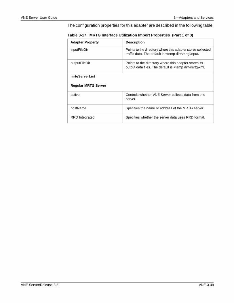
VNE Server User Guide 3—Adapters and Services
The configuration properties for this adapter are described in the following table.
Table 3-17 MRTG Interface Utilization Import Properties (Part 1 of 3)
Adapter Property Description
inputFileDir Points to the directory where this adapter stores collected traffic data. The default is <temp dir>\mrtg\input.
outputFileDir Points to the directory where this adapter stores its output data files. The default is <temp dir>\mrtg\xml.
mrtgServerList
Regular MRTG Server
active Controls whether VNE Server collects data from this server.
hostName Specifies the name or address of the MRTG server.
RRD Integrated Specifies whether the server data uses RRD format.
VNE Server/Release 3.5 VNE-3-49
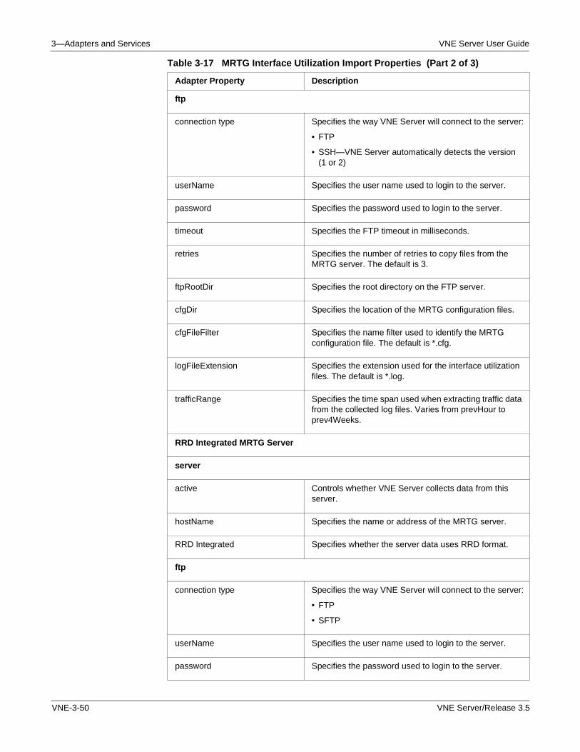
3—Adapters and Services VNE Server User Guide
ftp
connection type Specifies the way VNE Server will connect to the server:
• FTP
• SSH—VNE Server automatically detects the version (1 or 2)
userName Specifies the user name used to login to the server.
password Specifies the password used to login to the server.
timeout Specifies the FTP timeout in milliseconds.
retries Specifies the number of retries to copy files from the MRTG server. The default is 3.
ftpRootDir Specifies the root directory on the FTP server.
cfgDir Specifies the location of the MRTG configuration files.
cfgFileFilter Specifies the name filter used to identify the MRTG configuration file. The default is *.cfg.
logFileExtension Specifies the extension used for the interface utilization files. The default is *.log.
trafficRange Specifies the time span used when extracting traffic data from the collected log files. Varies from prevHour to prev4Weeks.
RRD Integrated MRTG Server
server
active Controls whether VNE Server collects data from this server.
hostName Specifies the name or address of the MRTG server.
RRD Integrated Specifies whether the server data uses RRD format.
ftp
connection type Specifies the way VNE Server will connect to the server:
• FTP
• SFTP
userName Specifies the user name used to login to the server.
password Specifies the password used to login to the server.
Table 3-17 MRTG Interface Utilization Import Properties (Part 2 of 3)
Adapter Property Description
VNE-3-50 VNE Server/Release 3.5
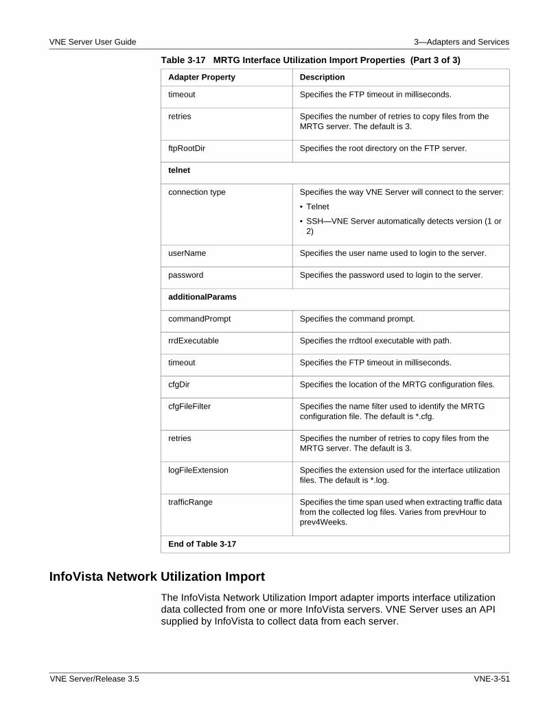
VNE Server User Guide 3—Adapters and Services
InfoVista Network Utilization Import
The InfoVista Network Utilization Import adapter imports interface utilization data collected from one or more InfoVista servers. VNE Server uses an API supplied by InfoVista to collect data from each server.
timeout Specifies the FTP timeout in milliseconds.
retries Specifies the number of retries to copy files from the MRTG server. The default is 3.
ftpRootDir Specifies the root directory on the FTP server.
telnet
connection type Specifies the way VNE Server will connect to the server:
• Telnet
• SSH—VNE Server automatically detects version (1 or 2)
userName Specifies the user name used to login to the server.
password Specifies the password used to login to the server.
additionalParams
commandPrompt Specifies the command prompt.
rrdExecutable Specifies the rrdtool executable with path.
timeout Specifies the FTP timeout in milliseconds.
cfgDir Specifies the location of the MRTG configuration files.
cfgFileFilter Specifies the name filter used to identify the MRTG configuration file. The default is *.cfg.
retries Specifies the number of retries to copy files from the MRTG server. The default is 3.
logFileExtension Specifies the extension used for the interface utilization files. The default is *.log.
trafficRange Specifies the time span used when extracting traffic data from the collected log files. Varies from prevHour to prev4Weeks.
End of Table 3-17
Table 3-17 MRTG Interface Utilization Import Properties (Part 3 of 3)
Adapter Property Description
VNE Server/Release 3.5 VNE-3-51
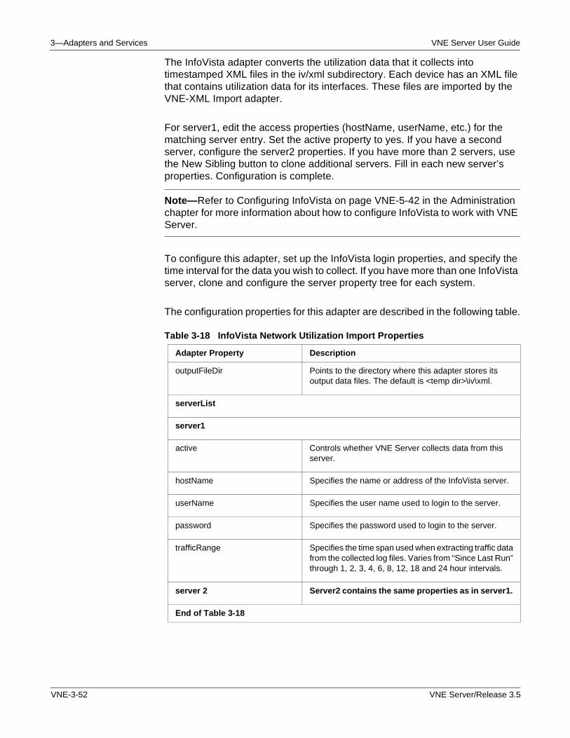
3—Adapters and Services VNE Server User Guide
The InfoVista adapter converts the utilization data that it collects into timestamped XML files in the iv/xml subdirectory. Each device has an XML file that contains utilization data for its interfaces. These files are imported by the VNE-XML Import adapter.
For server1, edit the access properties (hostName, userName, etc.) for the matching server entry. Set the active property to yes. If you have a second server, configure the server2 properties. If you have more than 2 servers, use the New Sibling button to clone additional servers. Fill in each new server’s properties. Configuration is complete.
Note—Refer to Configuring InfoVista on page VNE-5-42 in the Administration chapter for more information about how to configure InfoVista to work with VNE Server.
To configure this adapter, set up the InfoVista login properties, and specify the time interval for the data you wish to collect. If you have more than one InfoVista server, clone and configure the server property tree for each system.
The configuration properties for this adapter are described in the following table.
Table 3-18 InfoVista Network Utilization Import Properties
Adapter Property Description
outputFileDir Points to the directory where this adapter stores its output data files. The default is <temp dir>\iv\xml.
serverList
server1
active Controls whether VNE Server collects data from this server.
hostName Specifies the name or address of the InfoVista server.
userName Specifies the user name used to login to the server.
password Specifies the password used to login to the server.
trafficRange Specifies the time span used when extracting traffic data from the collected log files. Varies from “Since Last Run” through 1, 2, 3, 4, 6, 8, 12, 18 and 24 hour intervals.
server 2 Server2 contains the same properties as in server1.
End of Table 3-18
VNE-3-52 VNE Server/Release 3.5
VNE Server User Guide 3—Adapters and Services
Demand Import and Processing
This section discusses the following adapters, which collect and import demand traffic flow data into the VNE Server database:
• Cisco Netflow Import
• NetScout nGenius Import
• Cflowd Import
The Demand Traffic Processing Service processes traffic flow data and maps flow endpoints to devices in the VNE Server network database. The Demand Traffic Rollup Service manages the amount of traffic flow data and deletes obsolete flow data.
Traffic Mapping Using Node Traffic Alias
Traffic demands whose endpoints are outside the network topology cannot be mapped to endpoints based on IP subnets. To address this issue, the Demand Traffic Processing Service has been enhanced to use node traffic aliases for mapping flow endpoints. After a demand traffic import adapter finishes, flows exist in the VNE Server database separate from the topology. Demands in this state are referred to as “unmapped.” These traffic flows must then be associated with the network topology by mapping the endpoints. In previous releases, the Demand Traffic Processing Service performed this mapping by subnets using primary addresses. In 3.0 mapping by subnet has been expanded to use secondary IP addresses. It has also been enhanced to map demand traffic flows using node traffic aliases.
Node traffic aliases can be imported into VNE Server using the ASCII Generic Data Import adapter. If there is UserTracking data stored in the CiscoWorks ANI database, it can be used to create node traffic aliases in VNE Server.
After traffic flows have been imported into the VNE Server database, use these steps to map flows to endpoints using node traffic aliases:
Procedure 3-2 Map Flows to Endpoints Using Node Traffic Aliases
1 Import node traffic aliases into VNE Server
Perform steps 1.1 through 1.5, for CiscoWorks ANI Database import, or 1.6 through 1.12 for ASCII Generic Data Import.
• Using the CiscoWorks ANI Database Import adapter
1.1 Open the Management Console, and select the Adapter Resources tab.
1.2 Expand CiscoWorks ANI Database Import.
1.3 Set includeUserTrackingInfo to yes (the default value is no).
VNE Server/Release 3.5 VNE-3-53
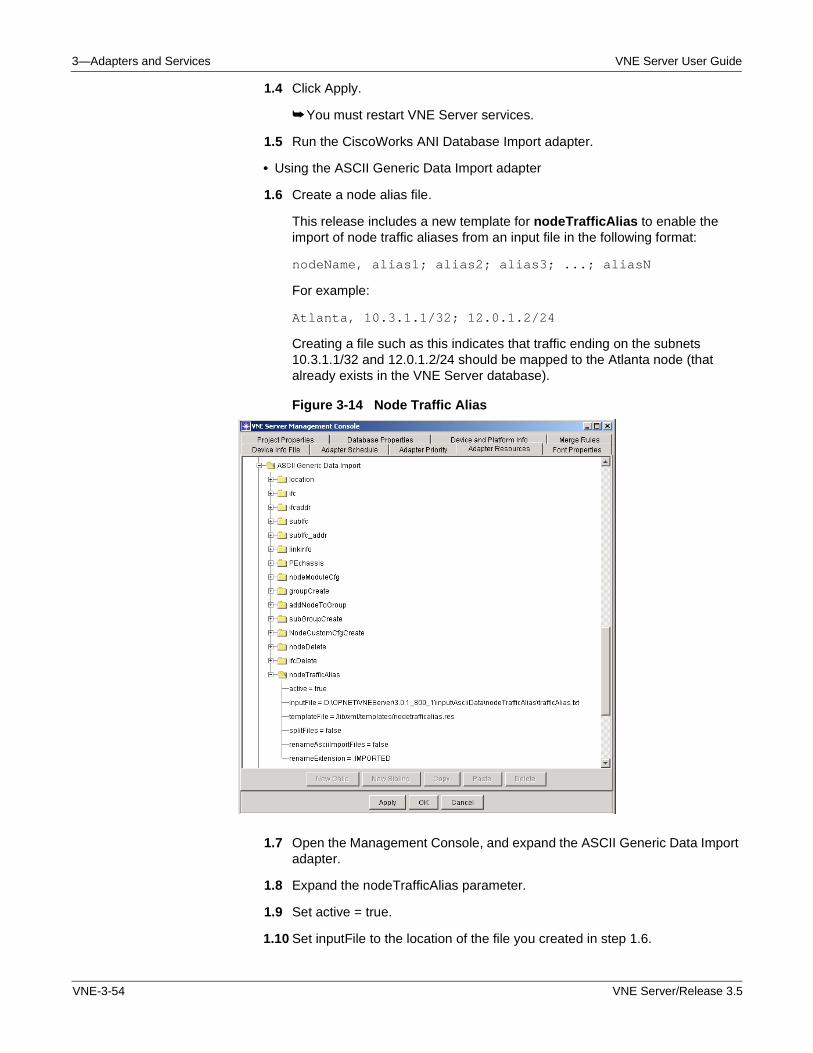
3—Adapters and Services VNE Server User Guide
1.4 Click Apply.
➥ You must restart VNE Server services.
1.5 Run the CiscoWorks ANI Database Import adapter.
• Using the ASCII Generic Data Import adapter
1.6 Create a node alias file.
This release includes a new template for nodeTrafficAlias to enable the import of node traffic aliases from an input file in the following format:
nodeName, alias1; alias2; alias3; ...; aliasN
For example:
Atlanta, 10.3.1.1/32; 12.0.1.2/24
Creating a file such as this indicates that traffic ending on the subnets 10.3.1.1/32 and 12.0.1.2/24 should be mapped to the Atlanta node (that already exists in the VNE Server database).
Figure 3-14 Node Traffic Alias
1.7 Open the Management Console, and expand the ASCII Generic Data Import adapter.
1.8 Expand the nodeTrafficAlias parameter.
1.9 Set active = true.
1.10 Set inputFile to the location of the file you created in step 1.6.
VNE-3-54 VNE Server/Release 3.5
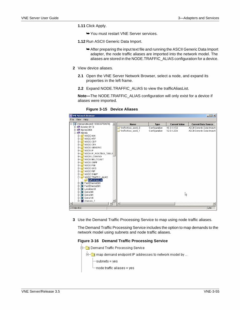
VNE Server User Guide 3—Adapters and Services
1.11 Click Apply.
➥ You must restart VNE Server services.
1.12 Run ASCII Generic Data Import.
➥ After preparing the input text file and running the ASCII Generic Data Import adapter, the node traffic aliases are imported into the network model. The aliases are stored in the NODE.TRAFFIC_ALIAS configuration for a device.
2 View device aliases.
2.1 Open the VNE Server Network Browser, select a node, and expand its properties in the left frame.
2.2 Expand NODE.TRAFFIC_ALIAS to view the trafficAliasList.
Note—The NODE.TRAFFIC_ALIAS configuration will only exist for a device if aliases were imported.
Figure 3-15 Device Aliases
3 Use the Demand Traffic Processing Service to map using node traffic aliases.
The Demand Traffic Processing Service includes the option to map demands to the network model using subnets and node traffic aliases.
Figure 3-16 Demand Traffic Processing Service
VNE Server/Release 3.5 VNE-3-55
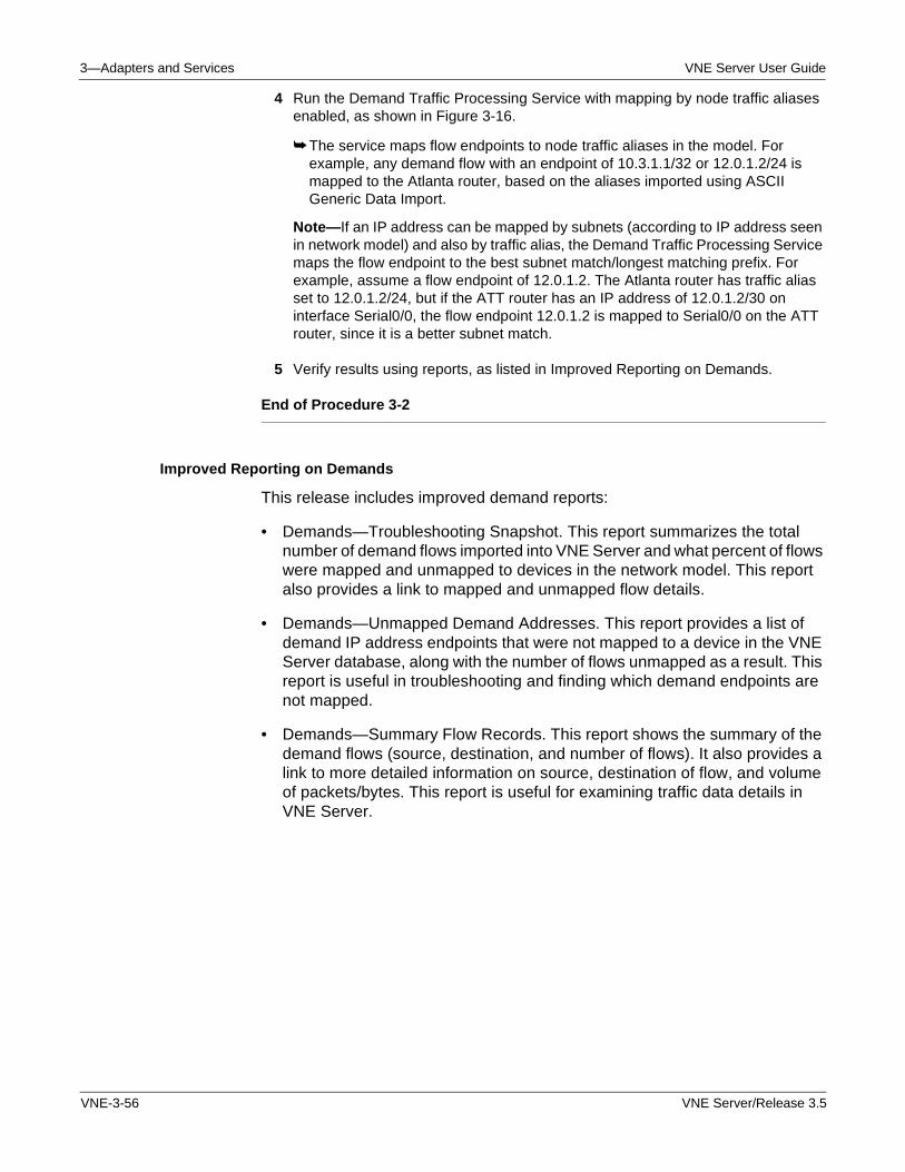
3—Adapters and Services VNE Server User Guide
4 Run the Demand Traffic Processing Service with mapping by node traffic aliases enabled, as shown in Figure 3-16.
➥ The service maps flow endpoints to node traffic aliases in the model. For example, any demand flow with an endpoint of 10.3.1.1/32 or 12.0.1.2/24 is mapped to the Atlanta router, based on the aliases imported using ASCII Generic Data Import.
Note—If an IP address can be mapped by subnets (according to IP address seen in network model) and also by traffic alias, the Demand Traffic Processing Service maps the flow endpoint to the best subnet match/longest matching prefix. For example, assume a flow endpoint of 12.0.1.2. The Atlanta router has traffic alias set to 12.0.1.2/24, but if the ATT router has an IP address of 12.0.1.2/30 on interface Serial0/0, the flow endpoint 12.0.1.2 is mapped to Serial0/0 on the ATT router, since it is a better subnet match.
5 Verify results using reports, as listed in Improved Reporting on Demands.
End of Procedure 3-2
Improved Reporting on Demands
This release includes improved demand reports:
• Demands—Troubleshooting Snapshot. This report summarizes the total number of demand flows imported into VNE Server and what percent of flows were mapped and unmapped to devices in the network model. This report also provides a link to mapped and unmapped flow details.
• Demands—Unmapped Demand Addresses. This report provides a list of demand IP address endpoints that were not mapped to a device in the VNE Server database, along with the number of flows unmapped as a result. This report is useful in troubleshooting and finding which demand endpoints are not mapped.
• Demands—Summary Flow Records. This report shows the summary of the demand flows (source, destination, and number of flows). It also provides a link to more detailed information on source, destination of flow, and volume of packets/bytes. This report is useful for examining traffic data details in VNE Server.
VNE-3-56 VNE Server/Release 3.5
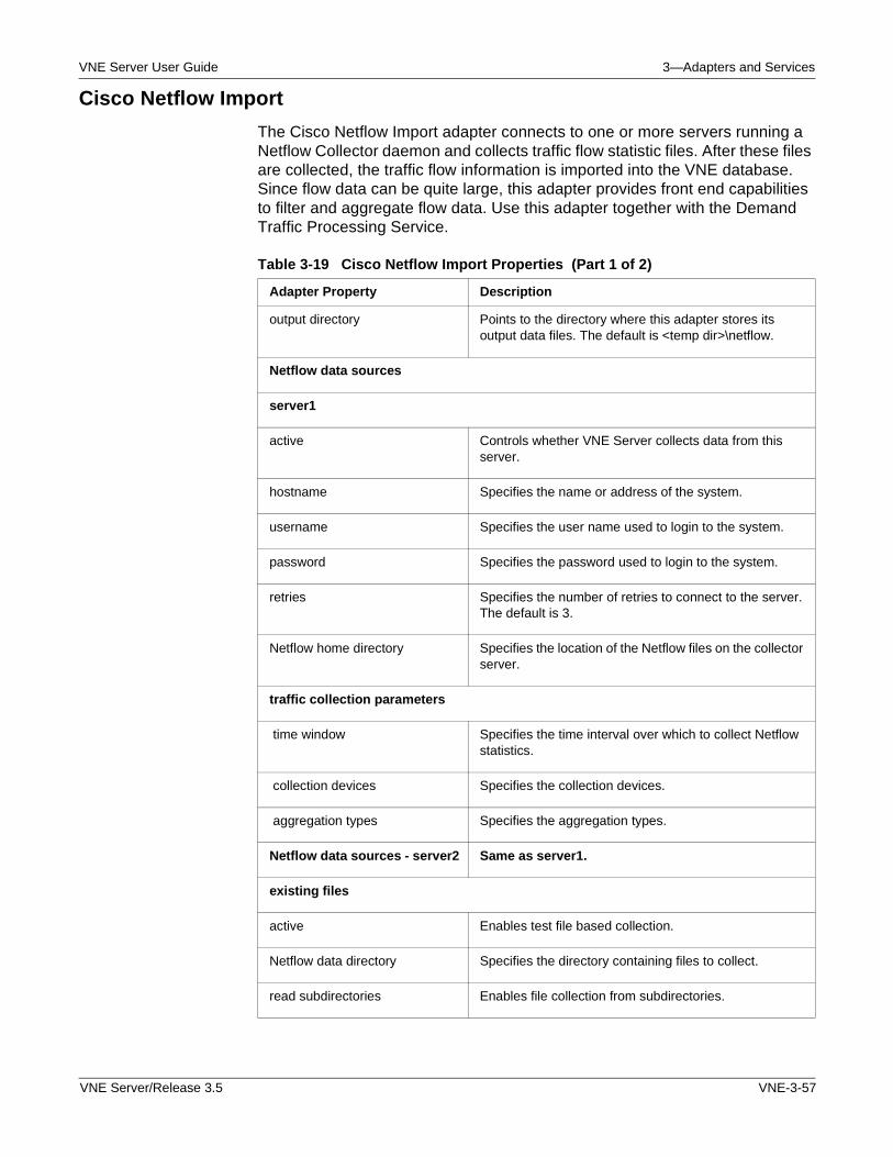
VNE Server User Guide 3—Adapters and Services
Cisco Netflow Import
The Cisco Netflow Import adapter connects to one or more servers running a Netflow Collector daemon and collects traffic flow statistic files. After these files are collected, the traffic flow information is imported into the VNE database. Since flow data can be quite large, this adapter provides front end capabilities to filter and aggregate flow data. Use this adapter together with the Demand Traffic Processing Service.
Table 3-19 Cisco Netflow Import Properties (Part 1 of 2)
Adapter Property Description
output directory Points to the directory where this adapter stores its output data files. The default is <temp dir>\netflow.
Netflow data sources
server1
active Controls whether VNE Server collects data from this server.
hostname Specifies the name or address of the system.
username Specifies the user name used to login to the system.
password Specifies the password used to login to the system.
retries Specifies the number of retries to connect to the server. The default is 3.
Netflow home directory Specifies the location of the Netflow files on the collector server.
traffic collection parameters
time window Specifies the time interval over which to collect Netflow statistics.
collection devices Specifies the collection devices.
aggregation types Specifies the aggregation types.
Netflow data sources - server2 Same as server1.
existing files
active Enables test file based collection.
Netflow data directory Specifies the directory containing files to collect.
read subdirectories Enables file collection from subdirectories.
VNE Server/Release 3.5 VNE-3-57
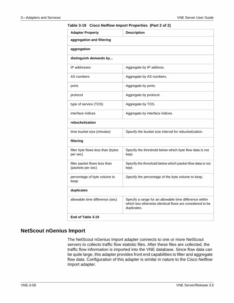
3—Adapters and Services VNE Server User Guide
NetScout nGenius Import
The NetScout nGenius Import adapter connects to one or more NetScout servers to collects traffic flow statistic files. After these files are collected, the traffic flow information is imported into the VNE database. Since flow data can be quite large, this adapter provides front end capabilities to filter and aggregate flow data. Configuration of this adapter is similar in nature to the Cisco Netflow Import adapter.
aggregation and filtering
aggregation
distinguish demands by...
IP addresses Aggregate by IP address.
AS numbers Aggregate by AS numbers.
ports Aggregate by ports.
protocol Aggregate by protocol.
type of service (TOS) Aggregate by TOS.
interface indices Aggregate by interface indices.
rebucketization
time bucket size (minutes) Specify the bucket size interval for rebucketization.
filtering
filter byte flows less than (bytes per sec)
Specify the threshold below which byte flow data is not kept.
filter packet flows less than (packets per sec)
Specify the threshold below which packet flow data is not kept.
percentage of byte volume to keep
Specify the percentage of the byte volume to keep.
duplicates
allowable time difference (sec) Specify a range for an allowable time difference within which two otherwise identical flows are considered to be duplicates.
End of Table 3-19
Table 3-19 Cisco Netflow Import Properties (Part 2 of 2)
Adapter Property Description
VNE-3-58 VNE Server/Release 3.5
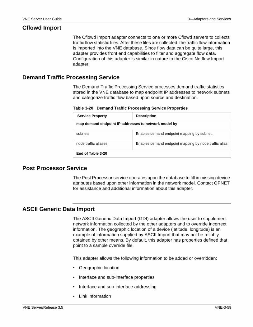
VNE Server User Guide 3—Adapters and Services
Cflowd Import
The Cflowd Import adapter connects to one or more Cflowd servers to collects traffic flow statistic files. After these files are collected, the traffic flow information is imported into the VNE database. Since flow data can be quite large, this adapter provides front end capabilities to filter and aggregate flow data. Configuration of this adapter is similar in nature to the Cisco Netflow Import adapter.
Demand Traffic Processing Service
The Demand Traffic Processing Service processes demand traffic statistics stored in the VNE database to map endpoint IP addresses to network subnets and categorize traffic flow based upon source and destination.
Post Processor Service
The Post Processor service operates upon the database to fill in missing device attributes based upon other information in the network model. Contact OPNET for assistance and additional information about this adapter.
ASCII Generic Data Import
The ASCII Generic Data Import (GDI) adapter allows the user to supplement network information collected by the other adapters and to override incorrect information. The geographic location of a device (latitude, longitude) is an example of information supplied by ASCII Import that may not be reliably obtained by other means. By default, this adapter has properties defined that point to a sample override file.
This adapter allows the following information to be added or overridden:
• Geographic location
• Interface and sub-interface properties
• Interface and sub-interface addressing
• Link information
Table 3-20 Demand Traffic Processing Service Properties
Service Property Description
map demand endpoint IP addresses to network model by
subnets Enables demand endpoint mapping by subnet.
node traffic aliases Enables demand endpoint mapping by node traffic alias.
End of Table 3-20
VNE Server/Release 3.5 VNE-3-59
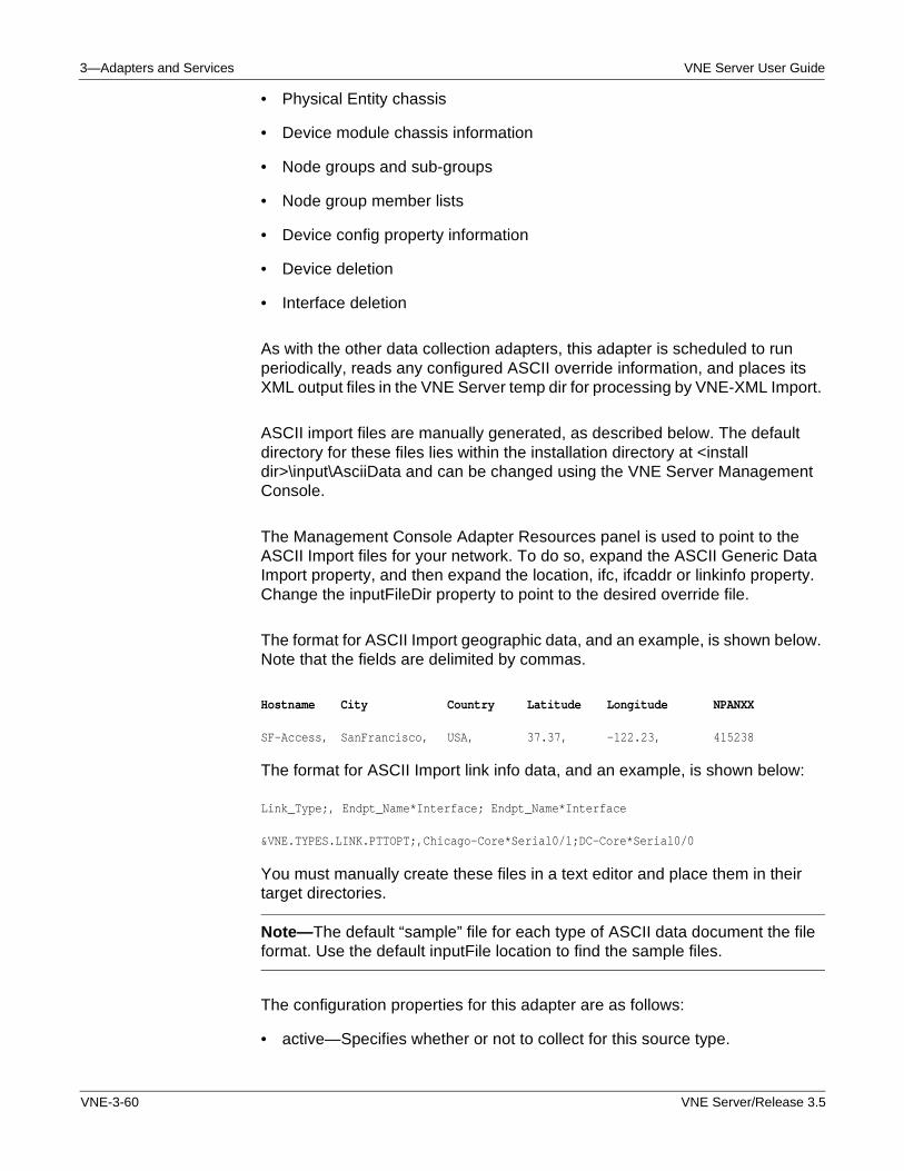
3—Adapters and Services VNE Server User Guide
• Physical Entity chassis
• Device module chassis information
• Node groups and sub-groups
• Node group member lists
• Device config property information
• Device deletion
• Interface deletion
As with the other data collection adapters, this adapter is scheduled to run periodically, reads any configured ASCII override information, and places its XML output files in the VNE Server temp dir for processing by VNE-XML Import.
ASCII import files are manually generated, as described below. The default directory for these files lies within the installation directory at <install dir>\input\AsciiData and can be changed using the VNE Server Management Console.
The Management Console Adapter Resources panel is used to point to the ASCII Import files for your network. To do so, expand the ASCII Generic Data Import property, and then expand the location, ifc, ifcaddr or linkinfo property. Change the inputFileDir property to point to the desired override file.
The format for ASCII Import geographic data, and an example, is shown below. Note that the fields are delimited by commas.
Hostname City Country Latitude Longitude NPANXX
SF-Access, SanFrancisco, USA, 37.37, -122.23, 415238
The format for ASCII Import link info data, and an example, is shown below:
Link_Type;, Endpt_Name*Interface; Endpt_Name*Interface
&VNE.TYPES.LINK.PTTOPT;,Chicago-Core*Serial0/1;DC-Core*Serial0/0
You must manually create these files in a text editor and place them in their target directories.
Note—The default “sample” file for each type of ASCII data document the file format. Use the default inputFile location to find the sample files.
The configuration properties for this adapter are as follows:
• active—Specifies whether or not to collect for this source type.
VNE-3-60 VNE Server/Release 3.5
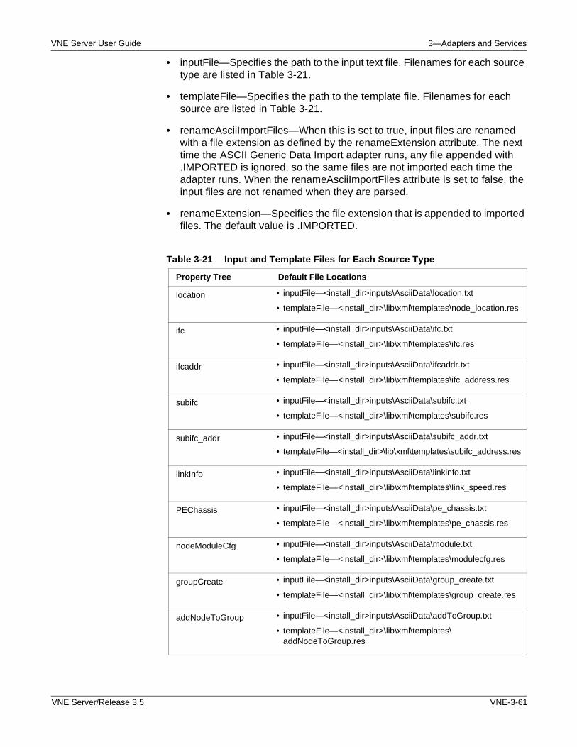
VNE Server User Guide 3—Adapters and Services
• inputFile—Specifies the path to the input text file. Filenames for each source type are listed in Table 3-21.
• templateFile—Specifies the path to the template file. Filenames for each source are listed in Table 3-21.
• renameAsciiImportFiles—When this is set to true, input files are renamed with a file extension as defined by the renameExtension attribute. The next time the ASCII Generic Data Import adapter runs, any file appended with .IMPORTED is ignored, so the same files are not imported each time the adapter runs. When the renameAsciiImportFiles attribute is set to false, the input files are not renamed when they are parsed.
• renameExtension—Specifies the file extension that is appended to imported files. The default value is .IMPORTED.
Table 3-21 Input and Template Files for Each Source Type
Property Tree Default File Locations
location • inputFile—<install_dir>inputs\AsciiData\location.txt
• templateFile—<install_dir>\lib\xml\templates\node_location.res
ifc • inputFile—<install_dir>inputs\AsciiData\ifc.txt
• templateFile—<install_dir>\lib\xml\templates\ifc.res
ifcaddr • inputFile—<install_dir>inputs\AsciiData\ifcaddr.txt
• templateFile—<install_dir>\lib\xml\templates\ifc_address.res
subifc • inputFile—<install_dir>inputs\AsciiData\subifc.txt
• templateFile—<install_dir>\lib\xml\templates\subifc.res
subifc_addr • inputFile—<install_dir>inputs\AsciiData\subifc_addr.txt
• templateFile—<install_dir>\lib\xml\templates\subifc_address.res
linkInfo • inputFile—<install_dir>inputs\AsciiData\linkinfo.txt
• templateFile—<install_dir>\lib\xml\templates\link_speed.res
PEChassis • inputFile—<install_dir>inputs\AsciiData\pe_chassis.txt
• templateFile—<install_dir>\lib\xml\templates\pe_chassis.res
nodeModuleCfg • inputFile—<install_dir>inputs\AsciiData\module.txt
• templateFile—<install_dir>\lib\xml\templates\modulecfg.res
groupCreate • inputFile—<install_dir>inputs\AsciiData\group_create.txt
• templateFile—<install_dir>\lib\xml\templates\group_create.res
addNodeToGroup • inputFile—<install_dir>inputs\AsciiData\addToGroup.txt
• templateFile—<install_dir>\lib\xml\templates\ addNodeToGroup.res
VNE Server/Release 3.5 VNE-3-61
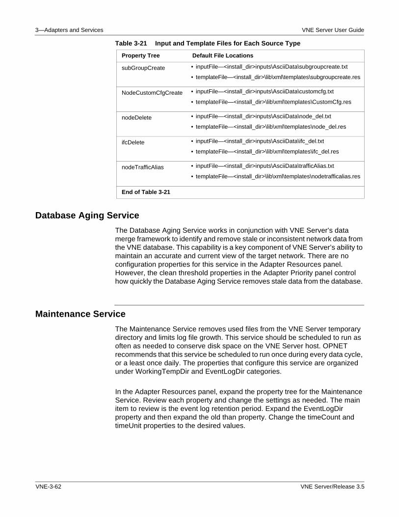
3—Adapters and Services VNE Server User Guide
Database Aging Service
The Database Aging Service works in conjunction with VNE Server’s data merge framework to identify and remove stale or inconsistent network data from the VNE database. This capability is a key component of VNE Server’s ability to maintain an accurate and current view of the target network. There are no configuration properties for this service in the Adapter Resources panel. However, the clean threshold properties in the Adapter Priority panel control how quickly the Database Aging Service removes stale data from the database.
Maintenance Service
The Maintenance Service removes used files from the VNE Server temporary directory and limits log file growth. This service should be scheduled to run as often as needed to conserve disk space on the VNE Server host. OPNET recommends that this service be scheduled to run once during every data cycle, or a least once daily. The properties that configure this service are organized under WorkingTempDir and EventLogDir categories.
In the Adapter Resources panel, expand the property tree for the Maintenance Service. Review each property and change the settings as needed. The main item to review is the event log retention period. Expand the EventLogDir property and then expand the old than property. Change the timeCount and timeUnit properties to the desired values.
subGroupCreate • inputFile—<install_dir>inputs\AsciiData\subgroupcreate.txt
• templateFile—<install_dir>\lib\xml\templates\subgroupcreate.res
NodeCustomCfgCreate • inputFile—<install_dir>inputs\AsciiData\customcfg.txt
• templateFile—<install_dir>\lib\xml\templates\CustomCfg.res
nodeDelete • inputFile—<install_dir>inputs\AsciiData\node_del.txt
• templateFile—<install_dir>\lib\xml\templates\node_del.res
ifcDelete • inputFile—<install_dir>inputs\AsciiData\ifc_del.txt
• templateFile—<install_dir>\lib\xml\templates\ifc_del.res
nodeTrafficAlias • inputFile—<install_dir>inputs\AsciiData\trafficAlias.txt
• templateFile—<install_dir>\lib\xml\templates\nodetrafficalias.res
End of Table 3-21
Table 3-21 Input and Template Files for Each Source Type
Property Tree Default File Locations
VNE-3-62 VNE Server/Release 3.5
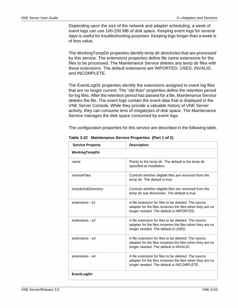
VNE Server User Guide 3—Adapters and Services
Depending upon the size of the network and adapter scheduling, a week of event logs can use 100-200 MB of disk space. Keeping event logs for several days is useful for troubleshooting purposes. Keeping logs longer than a week is of less value.
The WorkingTempDir properties identify temp dir directories that are processed by this service. The extensions properties define file name extensions for the files to be processed. The Maintenance Service deletes any temp dir files with these extensions. The default extensions are IMPORTED, USED, INVALID, and INCOMPLETE.
The EventLogDir properties identify the extensions assigned to event log files that are no longer current. The “old than” properties define the retention period for log files. After the retention period has passed for a file, Maintenance Service deletes the file. The event logs contain the event data that is displayed in the VNE Server Console. While they provide a valuable history of VNE Server activity, they can consume tens of megabytes of disk space. The Maintenance Service manages the disk space consumed by event logs.
The configuration properties for this service are described in the following table.
Table 3-22 Maintenance Service Properties (Part 1 of 2)
Service Property Description
WorkingTempDir
name Points to the temp dir. The default is the temp dir specified at installation.
removeFiles Controls whether eligible files are removed from the temp dir. The default is true.
includeSubDirectory Controls whether eligible files are removed from the temp dir sub directories. The default is true.
extensions - e1 A file extension for files to be deleted. The source adapter for the files renames the files when they are no longer needed. The default is IMPORTED.
extensions - e2 A file extension for files to be deleted. The source adapter for the files renames the files when they are no longer needed. The default is USED.
extensions - e3 A file extension for files to be deleted. The source adapter for the files renames the files when they are no longer needed. The default is INVALID.
extensions - e4 A file extension for files to be deleted. The source adapter for the files renames the files when they are no longer needed. The default is INCOMPLETE.
EventLogDir
VNE Server/Release 3.5 VNE-3-63
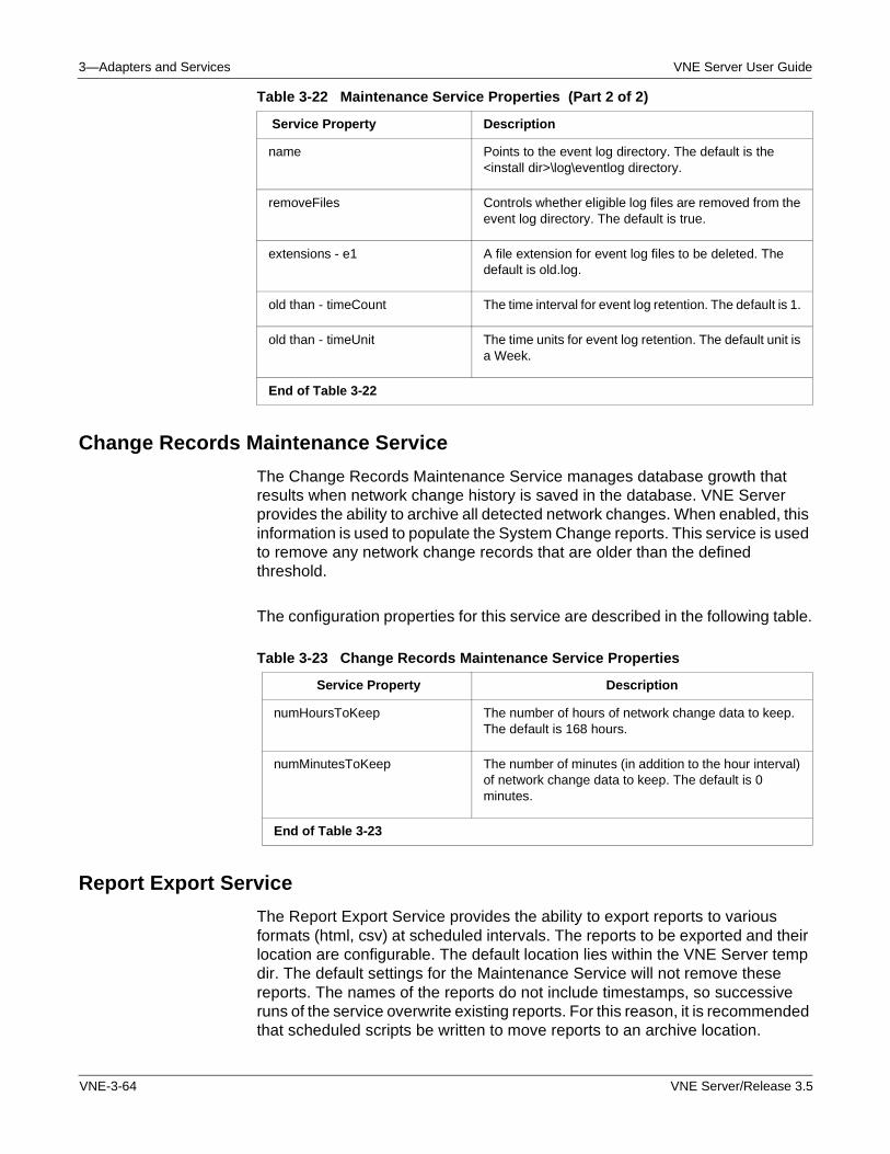
3—Adapters and Services VNE Server User Guide
Change Records Maintenance Service
The Change Records Maintenance Service manages database growth that results when network change history is saved in the database. VNE Server provides the ability to archive all detected network changes. When enabled, this information is used to populate the System Change reports. This service is used to remove any network change records that are older than the defined threshold.
The configuration properties for this service are described in the following table.
Report Export Service
The Report Export Service provides the ability to export reports to various formats (html, csv) at scheduled intervals. The reports to be exported and their location are configurable. The default location lies within the VNE Server temp dir. The default settings for the Maintenance Service will not remove these reports. The names of the reports do not include timestamps, so successive runs of the service overwrite existing reports. For this reason, it is recommended that scheduled scripts be written to move reports to an archive location.
name Points to the event log directory. The default is the <install dir>\log\eventlog directory.
removeFiles Controls whether eligible log files are removed from the event log directory. The default is true.
extensions - e1 A file extension for event log files to be deleted. The default is old.log.
old than - timeCount The time interval for event log retention. The default is 1.
old than - timeUnit The time units for event log retention. The default unit is a Week.
End of Table 3-22
Table 3-22 Maintenance Service Properties (Part 2 of 2)
Service Property Description
Table 3-23 Change Records Maintenance Service Properties
Service Property Description
numHoursToKeep The number of hours of network change data to keep. The default is 168 hours.
numMinutesToKeep The number of minutes (in addition to the hour interval) of network change data to keep. The default is 0 minutes.
End of Table 3-23
VNE-3-64 VNE Server/Release 3.5
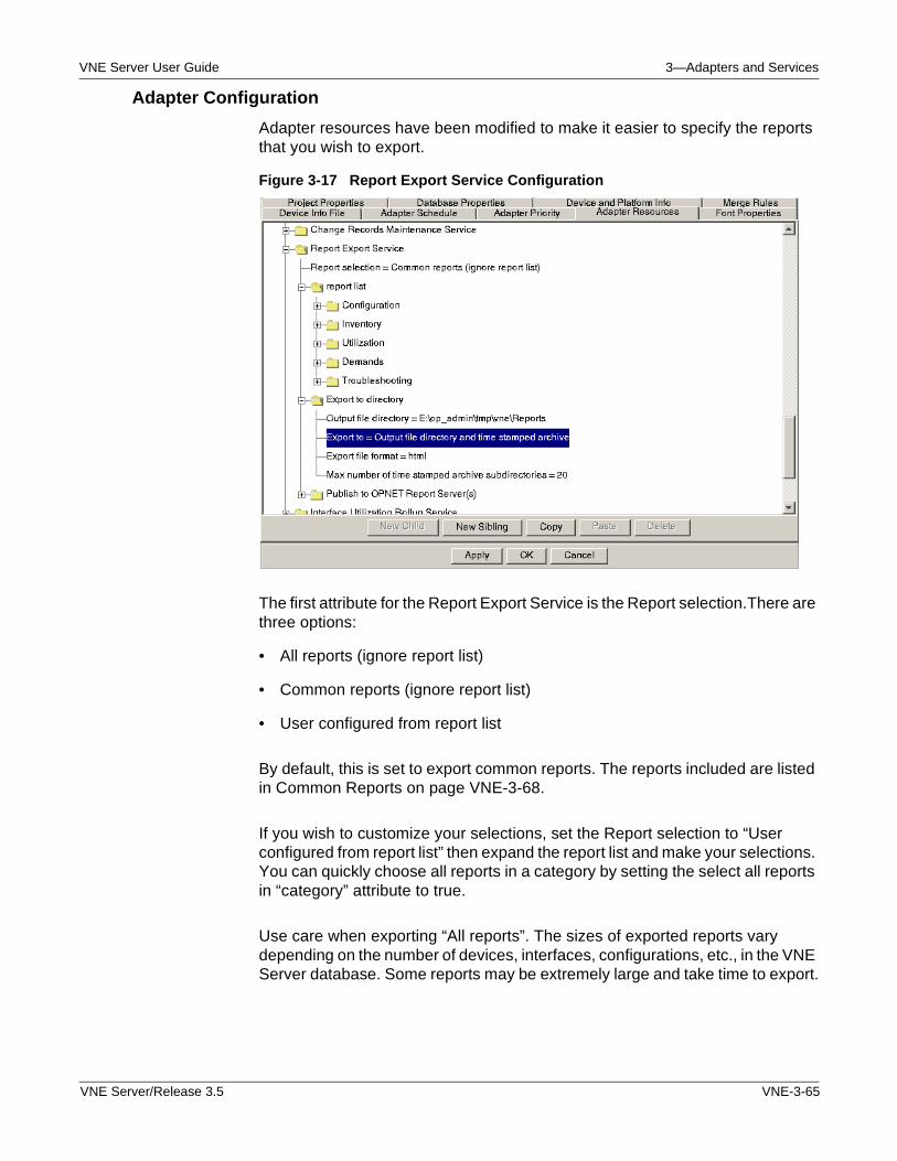
VNE Server User Guide 3—Adapters and Services
Adapter Configuration
Adapter resources have been modified to make it easier to specify the reports that you wish to export.
Figure 3-17 Report Export Service Configuration
The first attribute for the Report Export Service is the Report selection.There are three options:
• All reports (ignore report list)
• Common reports (ignore report list)
• User configured from report list
By default, this is set to export common reports. The reports included are listed in Common Reports on page VNE-3-68.
If you wish to customize your selections, set the Report selection to “User configured from report list” then expand the report list and make your selections. You can quickly choose all reports in a category by setting the select all reports in “category” attribute to true.
Use care when exporting “All reports”. The sizes of exported reports vary depending on the number of devices, interfaces, configurations, etc., in the VNE Server database. Some reports may be extremely large and take time to export.
VNE Server/Release 3.5 VNE-3-65
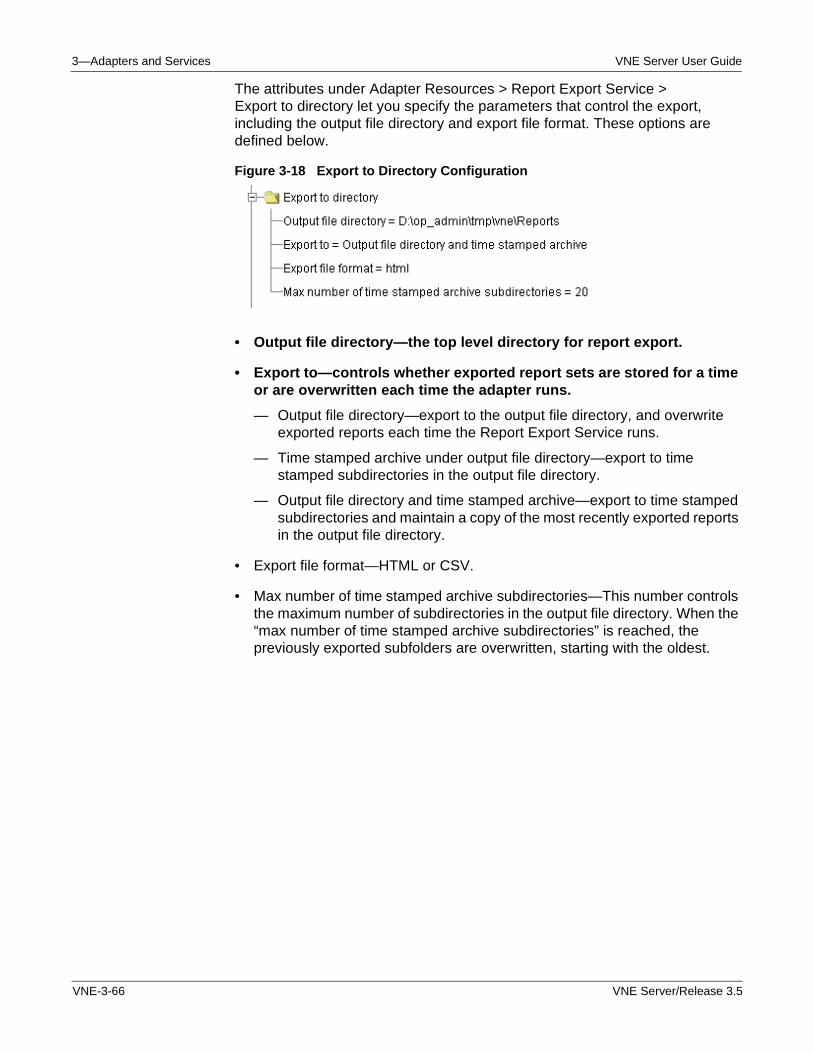
3—Adapters and Services VNE Server User Guide
The attributes under Adapter Resources > Report Export Service > Export to directory let you specify the parameters that control the export, including the output file directory and export file format. These options are defined below.
Figure 3-18 Export to Directory Configuration
• Output file directory—the top level directory for report export.
• Export to—controls whether exported report sets are stored for a time or are overwritten each time the adapter runs.
— Output file directory—export to the output file directory, and overwrite exported reports each time the Report Export Service runs.
— Time stamped archive under output file directory—export to time stamped subdirectories in the output file directory.
— Output file directory and time stamped archive—export to time stamped subdirectories and maintain a copy of the most recently exported reports in the output file directory.
• Export file format—HTML or CSV.
• Max number of time stamped archive subdirectories—This number controls the maximum number of subdirectories in the output file directory. When the “max number of time stamped archive subdirectories” is reached, the previously exported subfolders are overwritten, starting with the oldest.
VNE-3-66 VNE Server/Release 3.5
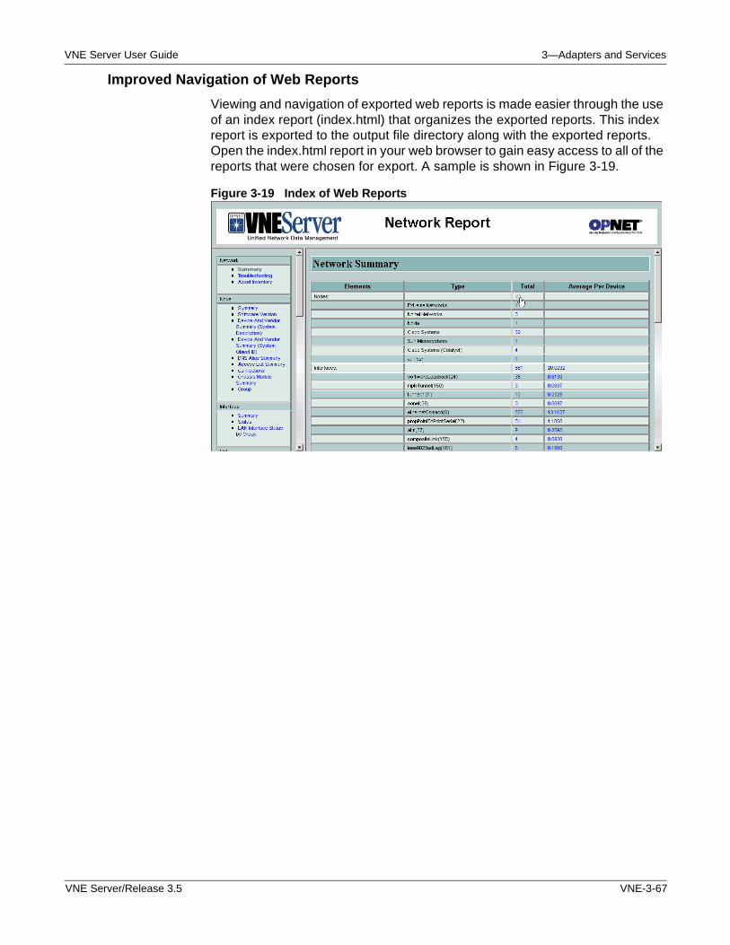
VNE Server User Guide 3—Adapters and Services
Improved Navigation of Web Reports
Viewing and navigation of exported web reports is made easier through the use of an index report (index.html) that organizes the exported reports. This index report is exported to the output file directory along with the exported reports. Open the index.html report in your web browser to gain easy access to all of the reports that were chosen for export. A sample is shown in Figure 3-19.
Figure 3-19 Index of Web Reports
VNE Server/Release 3.5 VNE-3-67
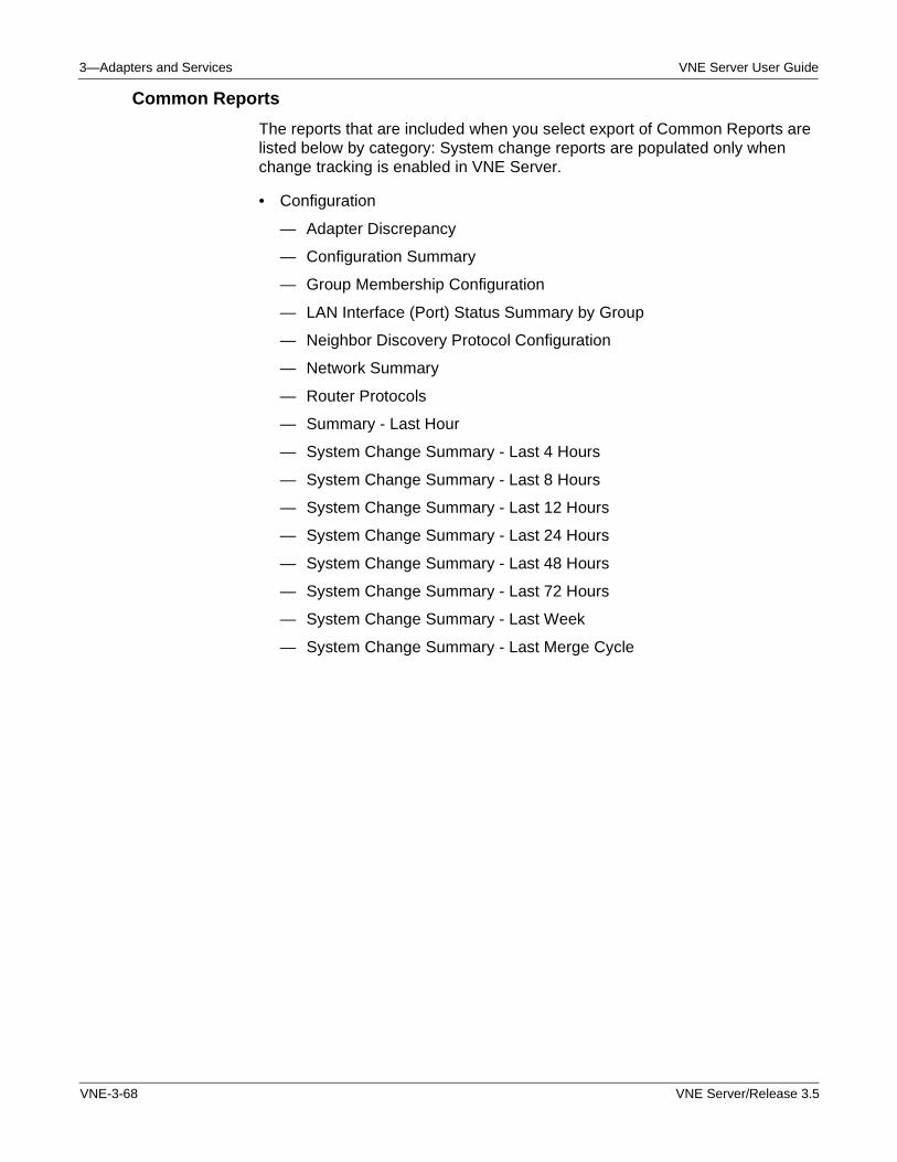
3—Adapters and Services VNE Server User Guide
Common Reports
The reports that are included when you select export of Common Reports are listed below by category: System change reports are populated only when change tracking is enabled in VNE Server.
• Configuration
— Adapter Discrepancy
— Configuration Summary
— Group Membership Configuration
— LAN Interface (Port) Status Summary by Group
— Neighbor Discovery Protocol Configuration
— Network Summary
— Router Protocols
— Summary - Last Hour
— System Change Summary - Last 4 Hours
— System Change Summary - Last 8 Hours
— System Change Summary - Last 12 Hours
— System Change Summary - Last 24 Hours
— System Change Summary - Last 48 Hours
— System Change Summary - Last 72 Hours
— System Change Summary - Last Week
— System Change Summary - Last Merge Cycle
VNE-3-68 VNE Server/Release 3.5
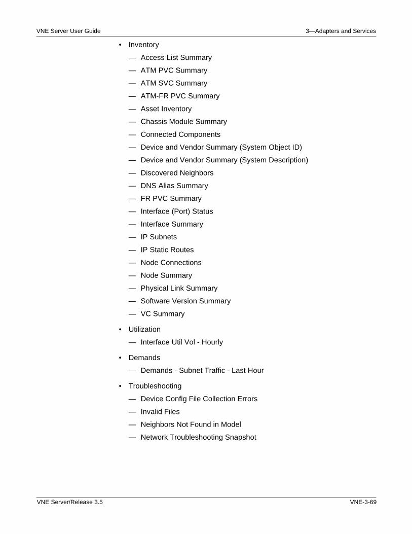
VNE Server User Guide 3—Adapters and Services
• Inventory
— Access List Summary
— ATM PVC Summary
— ATM SVC Summary
— ATM-FR PVC Summary
— Asset Inventory
— Chassis Module Summary
— Connected Components
— Device and Vendor Summary (System Object ID)
— Device and Vendor Summary (System Description)
— Discovered Neighbors
— DNS Alias Summary
— FR PVC Summary
— Interface (Port) Status
— Interface Summary
— IP Subnets
— IP Static Routes
— Node Connections
— Node Summary
— Physical Link Summary
— Software Version Summary
— VC Summary
• Utilization
— Interface Util Vol - Hourly
• Demands
— Demands - Subnet Traffic - Last Hour
• Troubleshooting
— Device Config File Collection Errors
— Invalid Files
— Neighbors Not Found in Model
— Network Troubleshooting Snapshot
VNE Server/Release 3.5 VNE-3-69
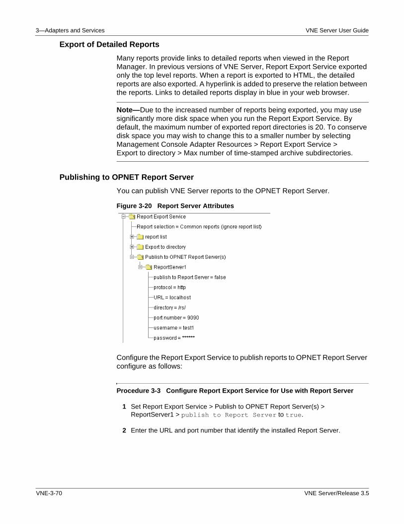
3—Adapters and Services VNE Server User Guide
Export of Detailed Reports
Many reports provide links to detailed reports when viewed in the Report Manager. In previous versions of VNE Server, Report Export Service exported only the top level reports. When a report is exported to HTML, the detailed reports are also exported. A hyperlink is added to preserve the relation between the reports. Links to detailed reports display in blue in your web browser.
Note—Due to the increased number of reports being exported, you may use significantly more disk space when you run the Report Export Service. By default, the maximum number of exported report directories is 20. To conserve disk space you may wish to change this to a smaller number by selecting Management Console Adapter Resources > Report Export Service > Export to directory > Max number of time-stamped archive subdirectories.
Publishing to OPNET Report Server
You can publish VNE Server reports to the OPNET Report Server.
Figure 3-20 Report Server Attributes
Configure the Report Export Service to publish reports to OPNET Report Server configure as follows:
Procedure 3-3 Configure Report Export Service for Use with Report Server
1 Set Report Export Service > Publish to OPNET Report Server(s) > ReportServer1 > publish to Report Server to true.
2 Enter the URL and port number that identify the installed Report Server.
VNE-3-70 VNE Server/Release 3.5
VNE Server User Guide 3—Adapters and Services
3 Enter a valid username and password.
Note—Make sure Report Server software is running when you run the Export Service.
End of Procedure 3-3
Interface Utilization Rollup Service
The Interface Utilization Rollup Service manages database growth resulting from the continuous import of interface utilization data. You must change the traffic retention intervals to the desired setting for each utilization source. With this service, utilization data is managed with respect to the following time periods:
• Interval over which raw utilization data is kept
• Interval over which utilization data is aggregated (rolled up) into fewer samples in the database
• Interval beyond which utilization data is removed from the database
WARNING—If you use any of the interface utilization adapters, you must run the Interface Utilization Rollup Service in order to control the growth of traffic data in the VNE database.
The configuration properties for this service are described in Table 3-24 for the following adapters.
• HP OpenView Performance Agent Import (NoRollup only)—Specify the amount of data you wish to keep, in DD:HH:MM format, and enable.
• Concord eHealth Network Utilization Import
• MIB-Based Interface Utilization Import
• MRTG Interface Utilization Import
• InfoVista Interface Utilization Import
VNE Server/Release 3.5 VNE-3-71
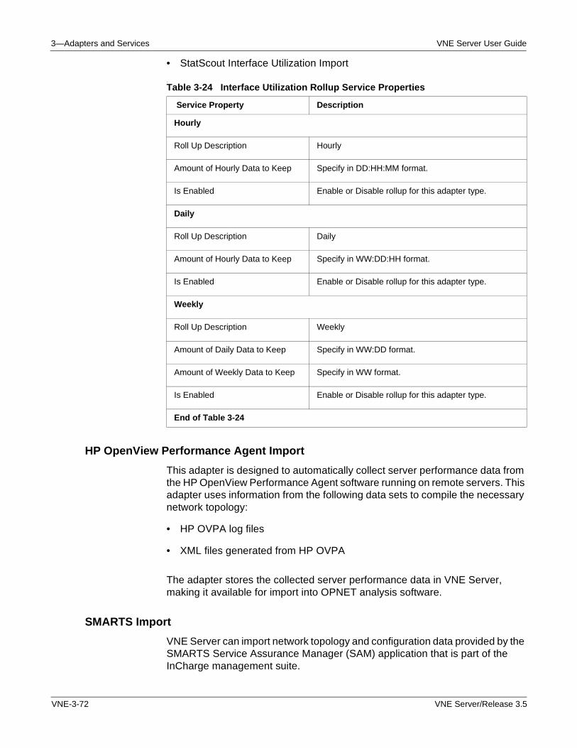
3—Adapters and Services VNE Server User Guide
• StatScout Interface Utilization Import
.
HP OpenView Performance Agent Import
This adapter is designed to automatically collect server performance data from the HP OpenView Performance Agent software running on remote servers. This adapter uses information from the following data sets to compile the necessary network topology:
• HP OVPA log files
• XML files generated from HP OVPA
The adapter stores the collected server performance data in VNE Server, making it available for import into OPNET analysis software.
SMARTS Import
VNE Server can import network topology and configuration data provided by the SMARTS Service Assurance Manager (SAM) application that is part of the InCharge management suite.
Table 3-24 Interface Utilization Rollup Service Properties
Service Property Description
Hourly
Roll Up Description Hourly
Amount of Hourly Data to Keep Specify in DD:HH:MM format.
Is Enabled Enable or Disable rollup for this adapter type.
Daily
Roll Up Description Daily
Amount of Hourly Data to Keep Specify in WW:DD:HH format.
Is Enabled Enable or Disable rollup for this adapter type.
Weekly
Roll Up Description Weekly
Amount of Daily Data to Keep Specify in WW:DD format.
Amount of Weekly Data to Keep Specify in WW format.
Is Enabled Enable or Disable rollup for this adapter type.
End of Table 3-24
VNE-3-72 VNE Server/Release 3.5
VNE Server User Guide 3—Adapters and Services
The SMARTS Import adapter takes data that has been previously exported from SMARTS (using the inCharge XML adapter) and imports it into the VNE Server database. Before you run the SMARTS Import adapter, the data must first be exported from the SMARTS SAM. VNE Server provides an extraction script that specifies the network elements and data to be exported in XML format.
External Adapter
The External Adapter provides a means to integrate outside tools and scripts into the schedule of adapters and services that you wish to run. Some use cases are
• Copy exported model files to an archive environment
• Copy exported reports to an archive environment
• Move config files or data files collected by other tools to the temp dir
• Run scripts and tools to manage the VNE Server environment
This adapter can run one or more external commands. By default, the shell of one external command is provided and disabled. Use the Management Console Adapter Resources panel for this adapter to fill in the details of the number of commands to run and their setup properties.
As an example, you can use this adapter to run a custom script that copies exported VNE Server reports to a web server, making them available to others within your organization.
VNE Server/Release 3.5 VNE-3-73
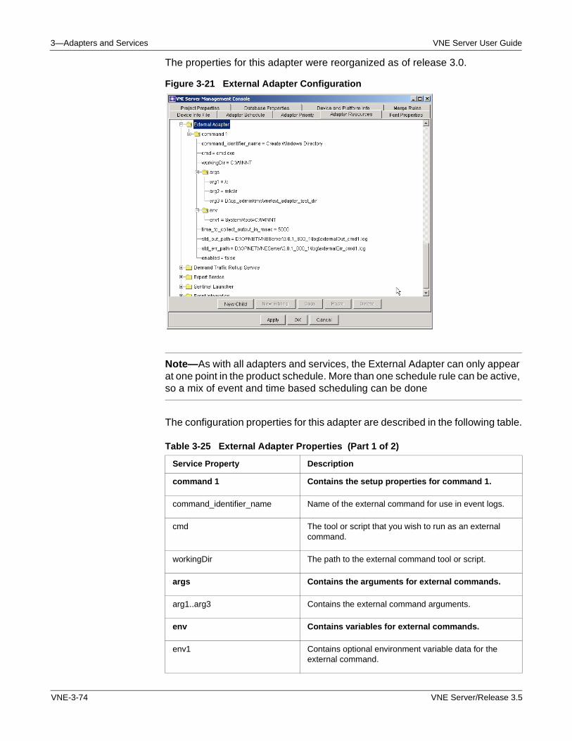
3—Adapters and Services VNE Server User Guide
The properties for this adapter were reorganized as of release 3.0.
Figure 3-21 External Adapter Configuration
Note—As with all adapters and services, the External Adapter can only appear at one point in the product schedule. More than one schedule rule can be active, so a mix of event and time based scheduling can be done
The configuration properties for this adapter are described in the following table.
Table 3-25 External Adapter Properties (Part 1 of 2)
Service Property Description
command 1 Contains the setup properties for command 1.
command_identifier_name Name of the external command for use in event logs.
cmd The tool or script that you wish to run as an external command.
workingDir The path to the external command tool or script.
args Contains the arguments for external commands.
arg1..arg3 Contains the external command arguments.
env Contains variables for external commands.
env1 Contains optional environment variable data for the external command.
VNE-3-74 VNE Server/Release 3.5
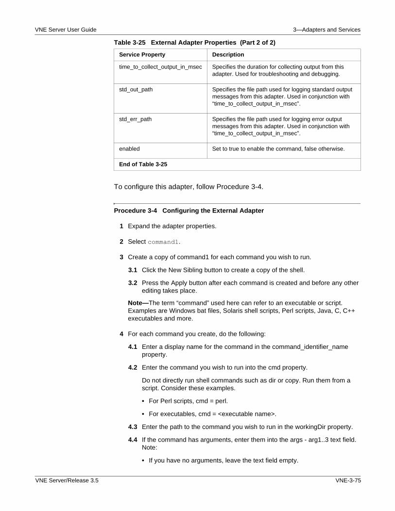
VNE Server User Guide 3—Adapters and Services
To configure this adapter, follow Procedure 3-4.
Procedure 3-4 Configuring the External Adapter
1 Expand the adapter properties.
2 Select command1.
3 Create a copy of command1 for each command you wish to run.
3.1 Click the New Sibling button to create a copy of the shell.
3.2 Press the Apply button after each command is created and before any other editing takes place.
Note—The term “command” used here can refer to an executable or script. Examples are Windows bat files, Solaris shell scripts, Perl scripts, Java, C, C++ executables and more.
4 For each command you create, do the following:
4.1 Enter a display name for the command in the command_identifier_name property.
4.2 Enter the command you wish to run into the cmd property.
Do not directly run shell commands such as dir or copy. Run them from a script. Consider these examples.
• For Perl scripts, cmd = perl.
• For executables, cmd = <executable name>.
4.3 Enter the path to the command you wish to run in the workingDir property.
4.4 If the command has arguments, enter them into the args - arg1..3 text field. Note:
• If you have no arguments, leave the text field empty.
time_to_collect_output_in_msec Specifies the duration for collecting output from this adapter. Used for troubleshooting and debugging.
std_out_path Specifies the file path used for logging standard output messages from this adapter. Used in conjunction with “time_to_collect_output_in_msec”.
std_err_path Specifies the file path used for logging error output messages from this adapter. Used in conjunction with “time_to_collect_output_in_msec”.
enabled Set to true to enable the command, false otherwise.
End of Table 3-25
Table 3-25 External Adapter Properties (Part 2 of 2)
Service Property Description
VNE Server/Release 3.5 VNE-3-75
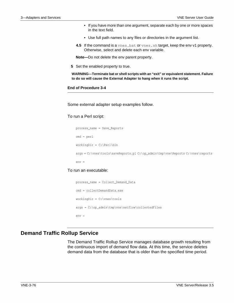
3—Adapters and Services VNE Server User Guide
• If you have more than one argument, separate each by one or more spaces in the text field.
• Use full path names to any files or directories in the argument list.
4.5 If the command is a vnes.bat or vnes.sh target, keep the env v1 property. Otherwise, select and delete each env variable.
Note—Do not delete the env parent property.
5 Set the enabled property to true.
WARNING—Terminate bat or shell scripts with an “exit” or equivalent statement. Failure to do so will cause the External Adapter to hang when it runs the script.
End of Procedure 3-4
Some external adapter setup examples follow.
To run a Perl script:
process_name = Save_Reports
cmd = perl
workingDir = C:\Perl\bin
args = C:\vnes\tools\saveReports.pl C:\op_admin\tmp\vne\Reports C:\vnes\reports
env =
To run an executable:
process_name = Collect_Demand_Data
cmd = collectDemandData.exe
workingDir = C:\vnes\tools
args = C:\op_admin\tmp\vne\netflow\collectedFiles
env =
Demand Traffic Rollup Service
The Demand Traffic Rollup Service manages database growth resulting from the continuous import of demand flow data. At this time, the service deletes demand data from the database that is older than the specified time period.
VNE-3-76 VNE Server/Release 3.5
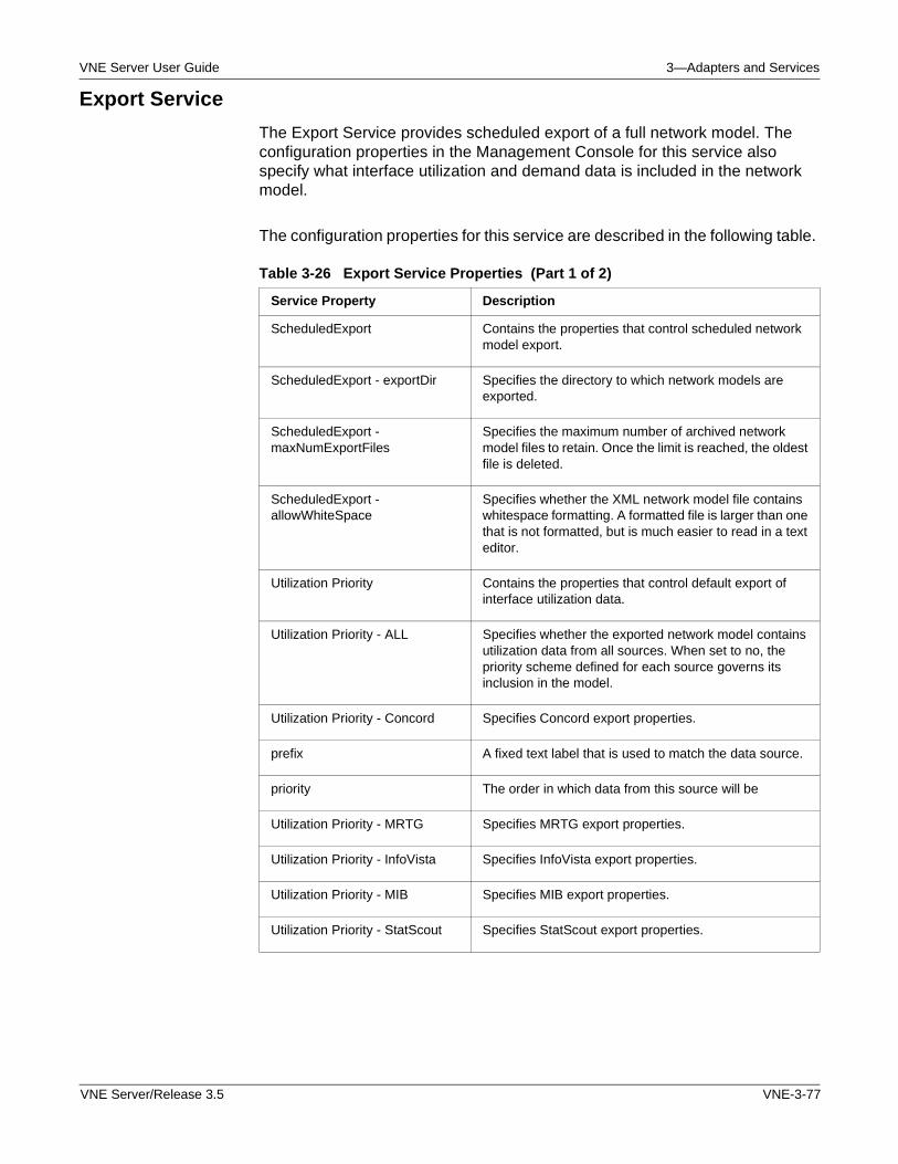
VNE Server User Guide 3—Adapters and Services
Export Service
The Export Service provides scheduled export of a full network model. The configuration properties in the Management Console for this service also specify what interface utilization and demand data is included in the network model.
The configuration properties for this service are described in the following table.
Table 3-26 Export Service Properties (Part 1 of 2)
Service Property Description
ScheduledExport Contains the properties that control scheduled network model export.
ScheduledExport - exportDir Specifies the directory to which network models are exported.
ScheduledExport - maxNumExportFiles
Specifies the maximum number of archived network model files to retain. Once the limit is reached, the oldest file is deleted.
ScheduledExport - allowWhiteSpace
Specifies whether the XML network model file contains whitespace formatting. A formatted file is larger than one that is not formatted, but is much easier to read in a text editor.
Utilization Priority Contains the properties that control default export of interface utilization data.
Utilization Priority - ALL Specifies whether the exported network model contains utilization data from all sources. When set to no, the priority scheme defined for each source governs its inclusion in the model.
Utilization Priority - Concord Specifies Concord export properties.
prefix A fixed text label that is used to match the data source.
priority The order in which data from this source will be
Utilization Priority - MRTG Specifies MRTG export properties.
Utilization Priority - InfoVista Specifies InfoVista export properties.
Utilization Priority - MIB Specifies MIB export properties.
Utilization Priority - StatScout Specifies StatScout export properties.
VNE Server/Release 3.5 VNE-3-77
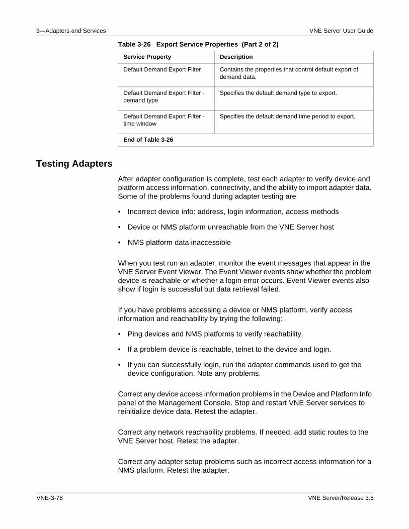
3—Adapters and Services VNE Server User Guide
Testing Adapters
After adapter configuration is complete, test each adapter to verify device and platform access information, connectivity, and the ability to import adapter data. Some of the problems found during adapter testing are
• Incorrect device info: address, login information, access methods
• Device or NMS platform unreachable from the VNE Server host
• NMS platform data inaccessible
When you test run an adapter, monitor the event messages that appear in the VNE Server Event Viewer. The Event Viewer events show whether the problem device is reachable or whether a login error occurs. Event Viewer events also show if login is successful but data retrieval failed.
If you have problems accessing a device or NMS platform, verify access information and reachability by trying the following:
• Ping devices and NMS platforms to verify reachability.
• If a problem device is reachable, telnet to the device and login.
• If you can successfully login, run the adapter commands used to get the device configuration. Note any problems.
Correct any device access information problems in the Device and Platform Info panel of the Management Console. Stop and restart VNE Server services to reinitialize device data. Retest the adapter.
Correct any network reachability problems. If needed, add static routes to the VNE Server host. Retest the adapter.
Correct any adapter setup problems such as incorrect access information for a NMS platform. Retest the adapter.
Default Demand Export Filter Contains the properties that control default export of demand data.
Default Demand Export Filter - demand type
Specifies the default demand type to export.
Default Demand Export Filter - time window
Specifies the default demand time period to export.
End of Table 3-26
Table 3-26 Export Service Properties (Part 2 of 2)
Service Property Description
VNE-3-78 VNE Server/Release 3.5

VNE Server User Guide 3—Adapters and Services
Continue to work through each of the adapters in this manner.
VNE Server/Release 3.5 VNE-3-79

3—Adapters and Services VNE Server User Guide
VNE-3-80 VNE Server/Release 3.5
VNE Server User Guide 4—Operation
4 Operation
Introduction
VNE Server is designed to operate autonomously as a network model server. After installation, an iterative setup process configures and tunes VNE Server for data collection from a particular target network. Once configuration is complete, continuous data collection is started and monitored through the VNE Server Console. The following sections describe the VNE Server configuration process, and how to manage network data collection.
WARNING—Before putting VNE Server into continuous operation, be sure that you are not running a version of DirectX that is older than 9.0.c. If necessary, upgrade your version of DirectX.
VNE Server/Release 3.5 VNE-4-1
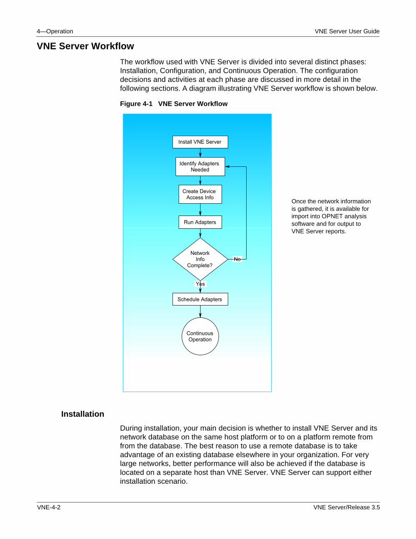
4—Operation VNE Server User Guide
VNE Server Workflow
The workflow used with VNE Server is divided into several distinct phases: Installation, Configuration, and Continuous Operation. The configuration decisions and activities at each phase are discussed in more detail in the following sections. A diagram illustrating VNE Server workflow is shown below.
Figure 4-1 VNE Server Workflow
Installation
During installation, your main decision is whether to install VNE Server and its network database on the same host platform or to on a platform remote from from the database. The best reason to use a remote database is to take advantage of an existing database elsewhere in your organization. For very large networks, better performance will also be achieved if the database is located on a separate host than VNE Server. VNE Server can support either installation scenario.
Identify Adapters Needed
Create Device Access Info
Run Adapters
NetworkInfo
Complete? No
Schedule Adapters
Yes
ContinuousOperation
Install VNE Server
Once the network information is gathered, it is available for import into OPNET analysis software and for output to VNE Server reports.
VNE-4-2 VNE Server/Release 3.5
VNE Server User Guide 4—Operation
Configuration
After installation, the next phase is the configuration of VNE Server for continuous operation, including adapter selection and configuration. This portion of the setup process is iterative and consists of the following stages:
• Identify the adapters needed based upon your network management environment. Use VNE Server’s third-party NMS adapters to leverage your other network management products as much as possible. Doing so minimizes the additional traffic required on your network to deliver a complete network model.
• Create the device access information used to guide VNE Server data collection.
• Configure and run each adapter individually. Evaluate data collection results. Reconfigure and retest until you are satisfied with the results.
• Use VNE Server’s Report Manager and Network Browser to determine the completeness of the network that is created.
• Import a network model into the OPNET analysis software to assess accuracy and completeness of the network model.
• Design a data collection schedule for the adapters. Consider how often adapters should run in order to maintain a current picture of your network.
Continuous Operation
Once adapter configuration and scheduling is defined, and any data collection problems are solved, you are ready to continuously run VNE Server as a network model server. In this role, VNE Server will build and maintain a complete view of your network. Anyone using the OPNET analysis software for network analysis can import a current network model whenever one is needed.
During continuous operation, you should monitor the VNE Server Event Viewer for any Critical or Emergency events that require investigation. The Report Manager and Network Browser are excellent tools to view device configuration, as well as global information about the network.
VNE Server/Release 3.5 VNE-4-3
4—Operation VNE Server User Guide
Starting VNE Server
VNE Server is started from the OPNET VNE Server 3.5 program group. This program group provides the selections shown in the following table:
Note—You must be logged in as Administrator for the VNE Server program group to be visible.
Procedure 4-1 Start VNE Server
1 Select Start > Programs.
2 Locate the OPNET VNE Server 3.5 program group.
3 Select OPNET VNE Server from the OPNET VNE Server 3.5 program group.
➥ Within a minute, the VNE Server Console opens, followed by the VNE Server Control Panel.
End of Procedure 4-1
A user that starts VNE Server can log off of the host while still permitting VNE Server to run in the background. When the next user successfully logs on to the VNE Server host, the VNE Server Console window opens.
Rebooting the VNE Server Host
The windows services installed by VNE Server are configured to start automatically so that VNE Server is launched and attempts to start services following a reboot. The VNE Server Console window opens automatically. The Control Panel windows does not open automatically. To access the Control Panel, select the File Menu or toolbar button in the Console window.
Table 4-1 OPNET VNE Server Program Group Selections
Program Group Selections Function
OPNET VNE Server Opens the VNE Server Console and Control Panel.
Open File Log Viewer Opens the VNE Server File Log Viewer.
Open Licensing Web Page Opens the OPNET License Registration web page in a browser.
OPNET VNE Server Documentation
Opens the VNE Server documentation menu in Acrobat Reader.
End of Table 4-1
VNE-4-4 VNE Server/Release 3.5
VNE Server User Guide 4—Operation
There may be circumstances where VNE Server may not be able to successfully launch and start services following a reboot. Please refer to Cannot Obtain a License When Starting VNE Server on page VNE-A-33, for additional information.
Configuring VNE Server
Setting up VNE Server for continuous operation involves decisions about the adapters you need, their setup, and their scheduling. Creating device access information for a large network can be a tedious task. Working through device access problems encountered during adapter testing involves troubleshooting. The following sections guide you through the configuration process.
Creating Device Access Information
VNE Server adapters that directly access devices in your network require a device file that contains access information about each device that you choose to include in the network model.
The device information file contains the hostnames, access addresses, and login information that VNE Server needs to collect configuration and MIB data from each device. By default, this file is located in the <install dir>\input\DeviceInfo directory as deviceInfo.txt, but it can have any name or location. The Device Info File panel in the Management Console has a property that points to this file. Refer to Device Info File on page VNE-2-41 and Device and Platform Info on page VNE-2-41 sections of the User Interface chapter for more information about the device file format and editing tools.
You can create the device info file in the following ways:
• Offline using device access data and scripts or spreadsheets
• Online within the Management Console
• By a combination of offline and online methods
Create a Device Info File Offline
Offline methods work best for creating an initial device information file for a large network. This is especially true if you already have files that list device names and their access addresses. You can use a spreadsheet to create the device file. To do so, perform the following steps.
1) Import your device name and address file into a spreadsheet.
2) Use the spreadsheet’s editing tools to fill in missing data. Refer to Format of the Device Info File on page VNE-C-1 for details on the file format.
VNE Server/Release 3.5 VNE-4-5
4—Operation VNE Server User Guide
3) Copy the file to the device file location configured in the Device Info File panel in the Management Console.
4) Open the Device and Platform Info panel to view the contents of the device file.
If the device data does not display as expected, verify that the field order and delimiter is correct. Correct any problems found.
Create a Device Info File Online
The Device and Platform Info panel is where you do online, interactive editing to create or maintain a device file. While you can use this panel to create access information for your entire network, it is less tedious to create large device files offline. The best use of this panel is to maintain an existing device file. Adding, removing, or changing device information for a small number of devices is easy.
This panel also provides the ability to import device information from the following sources.
• CiscoWorks inventory files—refer toUsing a CiscoWorks Inventory File to Create a Device Info File on page VNE-2-46 in the User Interface chapter.
• Concord dci files—refer to Using a Concord dci File to Create a Device Info File on page VNE-2-46 in the User Interface chapter.
• HP OpenView NNM Server—refer to Using HP OpenView NNM Server to Create a Device Info File on page VNE-2-47 in the User Interface chapter.
• VNE Database—refer to Using the Contents of the VNE Database to Create a Device Info File on page VNE-2-47 in the User Interface chapter.
The device files from these sources are still partial files. Once the device file is created, import it into a spreadsheet and fill in the missing fields. When done, export the file back to text format. Make sure you use a field delimiter that matches the one specified by the delimiter property in the Device Info File panel.
Note—Some types of devices need to be separated into multiple entries in the device info file. For example, Cisco Catalyst devices consist of 2 switching cores and additional routing modules. In this case, each addressable module should appear as an entry in the device info file. Interface and port modules do not need to be handled in this fashion. Systems from other vendors may require similar treatment.
Once you have created a device info file, you are ready to select, configure, and test the adapters.
VNE-4-6 VNE Server/Release 3.5
VNE Server User Guide 4—Operation
Choosing Adapters
VNE Server offers a comprehensive selection of data collection adapters. Some adapters collect data directly from each device in the network. Others collect data from other NMS platforms such as CiscoWorks, HP OpenView, or Concord.
The adapters that you choose to use depend mainly upon the following considerations:
• Other NMS platforms used in the network
• Device vendor mix
• Policy restrictions regarding SNMP use
• ASCII data requirements
The presence of other network management systems in your network has the biggest effect on adapter selection. For each of your third-party NMS platforms, use the corresponding VNE Server adapter to collect their data. For more information on particular adapters, refer to the Adapters and Services chapter of this manual.
CiscoWorks Adapters
For CiscoWorks, the choices are more varied. VNE Server provides separate adapters to collect configuration files from CiscoWorks and to access the RME and ANI databases. Use the adapters that correspond to your CiscoWorks components.
Since the VNE Server device configuration adapters collects more information than CiscoWorks, consider running the following adapters to maximize the data collected from each device:
• Device Config File Collection
• Device ifIndex Import
• Device FR Map Import
• Device Version Import
• Device IP Route Import
• Device CDP Import
• Device ARP Table Import
• Device Interface Import
• Device Module Import
• Device VTP Status Import
VNE Server/Release 3.5 VNE-4-7
4—Operation VNE Server User Guide
• Device CAM Table Import
• Device VLAN Database Import
Note—Refer to Device Config File Collection on page VNE-3-1 in the Adapters and Services chapter for a list of the commands used to gather device configuration data for each supported vendor.
The device vendors present in your network also affect the adapters to use. In a network consisting only of Cisco devices with a full CiscoWorks implementation, you may be able to omit the following adapters and still obtain a complete network model:
• Device Config File Collection
• Device Config File (ifIndex, FR Map, Version, IP Route, CDP, ARP Table, Interface, Module, VTP Status, CAM Table, VLAN Database) Import
• Device MIB Configuration Import
In a mixed vendor network, run all of these adapters to build a complete network. For this scenario, you may omit the Cisco devices from the device info file, since CiscoWorks supplies configuration data for these devices.
Collecting Utilization Data
VNE Server supports several adapters that import interface utilization data.
• Concord eHealth and MRTG—If you use some combination of Concord eHealth and MRTG, use the corresponding VNE Server adapters to import the data. You do not need to use the MIB-Based Interface Utilization Import adapter. You only need this adapter if there is no other source of interface utilization data.
• SNMP Polling Policies—Network management policies regarding SNMP polling also affect your adapter choices. If your organization tightly restricts SNMP polling, consider whether the data collected by the Device MIB Configuration Import and MIB-Based Interface Utilization Import adapters is worth the additional traffic on your network.
• Geographic Data Import—VNE Server provides the ASCII Generic Data Import adapter to support import of geographic location and link override data. Consider whether you need this adapter to build a complete network.
• Network Link Information—Use the Link and Connection Inference Service. If you do not use HP OpenView, this service is the only way to create links for your network. For HP OpenView users, VNE Server can infer additional network links based upon the broader set of data available to VNE Server. Do not rely solely upon HP OpenView for creation of network links.
VNE-4-8 VNE Server/Release 3.5
VNE Server User Guide 4—Operation
• Framework Services—Always use the framework services: Database Aging Service, Maintenance Service, Demand Traffic Rollup Service, Interface Utilization Rollup Service and the Change Records Maintenance Service. These services perform essential housekeeping for VNE Server.
— The Database Aging Service removes stale data from the database.
— The Maintenance Service removes outdated files from the file system.
— The Demand Traffic Rollup and Interface Utilization Rollup services remove old demand and interface utilization data from the database.
— If you have enabled archival of network changes, use the Change Records Maintenance Service to manage the growth of network change history in the database.
Once you have chosen the adapters that best fit your network management environment and modeling needs, you are ready to configure and test each adapter.
Configuring and Testing Adapters
Once you have created device access information about your network, and have chosen adapters, you must configure each adapter for operation. Use the Adapter Resources panel in the Management Console to evaluate each adapter property. Change adapter properties, as needed, to configure adapters for your network.
Note—Before you configure adapters, review Management Console on page VNE-2-34 in the User Interface chapter to learn more about user interfaces in the Management Console. For each adapter that you need, review its description in the Adapters and Services chapter.
Evaluating the Network Model
After all adapters have been tested and setup problems corrected, use the VNE Server Report Manager and Network Browser to examine the network. Import the network into an OPNET analysis software project. Examine the topology, configuration and traffic imported into the OPNET analysis software model from VNE Server. As you evaluate the network model created by VNE Server, you may find
• Missing devices
• Unexpected devices
• Missing links or a disconnected topology
• Incorrect interface speeds
VNE Server/Release 3.5 VNE-4-9
4—Operation VNE Server User Guide
Investigate anything that appears incorrect based upon your knowledge of the network.
• Missing devices generally result from an incomplete device info file.
• Unexpected devices can be created due to configuration problems or stale data from NMS platforms. ASCII data files created by the user for the ASCII Generic Data Import adapter may have devices that do not belong in the network.
• Missing links can mean that the adapters in use do not provide enough information to infer the link. Consider whether running adapters that are not being used will populate additional data that can aid link inference. Missing links may also be due to portions of the network being isolated by firewalls or other unmodeled devices.
• Incorrect interface speeds may be the result of ambiguous configuration data.
Manually run the Trace Route Link Inference Service to fill in missing devices and links. This service discovers “hidden” devices in your network and adds them to the device info file. Fill in empty fields for these new devices so that other adapters can collect data from them to produce a richer network model.
Correct all problems found in both adapter setup and NMS platforms. Rerun adapters. Use the Report Manager and Network Browser to examine network data. You can usually see whether a problem has been fixed with these tools. Try another model import into an OPNET analysis software project. Iterate until the network model is the best that can be obtained, and the causes of missing devices, links or data are understood.
Once you have finalized adapter configuration, you are ready to configure the adapter schedules.
Scheduling Adapters
The last configuration step before putting VNE Server into continuous operation is to configure adapter schedules. VNE Server provides complete flexibility in scheduling adapter operation. You can schedule adapters to run on a regular basis, or you can schedule adapters to run based upon events raised by other adapters. In practice, you will likely use a mix of both scheduling methods.
Since the VNE-XML Import service imports all the data supplied by adapters into the network database, it is important to not over-schedule the adapters. Doing so overloads the VNE-XML Import service, which causes it to fall behind. Using event-based scheduling, as much as possible, results in the most efficient operation for VNE Server and the most current network model.
VNE-4-10 VNE Server/Release 3.5
VNE Server User Guide 4—Operation
When scheduling adapters, consider the following questions.
• How often does the network configuration change?
• How large is the network?
• How often should each adapter poll the network?
• Do you want some adapters to poll more than once in a data cycle?
• How often do the third-party NMS products poll the network?
The answers to these questions help determine how you schedule the adapters. For example, if you have a daily maintenance window for changing your network configuration, scheduling all adapters to run 4 times a day will add little to no value.
The size of your network also affects scheduling decisions. If all the adapters that you want to run need 4 hours to poll the network and import data into the database, then 4 hours is the shortest polling interval that can be used if you are using time-based scheduling.
The polling behavior of third-party NMS products affect your adapter scheduling decisions. If a third-party NMS product polls the network every 4 hours, there is no value in scheduling the corresponding VNE Server adapter to run any sooner than this interval.
MIB-Based Interface Utilization Import Adapter
The MIB-Based Interface Utilization Import adapter presents a special case. This adapter polls the network based upon its sampleInterval property, not the scheduled adapter time. The scheduled time refers to when the adapter processes its collected data and produces XML data files for import by the VNE-XML Import adapter. With this adapter, you have the option to poll and collect data more often than you import the data. You do not need to import data after each polling cycle, but should not let more than about 6 to 12 polling cycles of data accumulate before the XML data is imported.
Chaining Adapters
The best way to schedule the VNE Server adapters is to use time-based scheduling for the third-party NMS adapters based upon the polling schedule of the corresponding NMS product.
VNE Server/Release 3.5 VNE-4-11
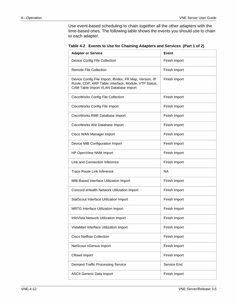
4—Operation VNE Server User Guide
Use event-based scheduling to chain together all the other adapters with the time-based ones. The following table shows the events you should use to chain to each adapter.
Table 4-2 Events to Use for Chaining Adapters and Services (Part 1 of 2)
Adapter or Service Event
Device Config File Collection Finish Import
Remote File Collection Finish Import
Device Config File Import, ifIndex, FR Map, Version, IP Route, CDP, ARP Table, Interface, Module, VTP Status, CAM Table Import VLAN Database Import
Finish Import
CiscoWorks Config File Collection Finish Import
CiscoWorks Config File Import Finish Import
CiscoWorks RME Database Import Finish Import
CiscoWorks ANI Database Import Finish Import
Cisco WAN Manager Import Finish Import
Device MIB Configuration Import Finish Import
HP OpenView NNM Import Finish Import
Link and Connection Inference Finish Import
Trace Route Link Inference NA
MIB-Based Interface Utilization Import Finish Import
Concord eHealth Network Utilization Import Finish Import
StatScout Interface Utilization Import Finish Import
MRTG Interface Utilization Import Finish Import
InfoVista Network Utilization Import Finish Import
VistaMart Interface Utilization Import Finish Import
Cisco Netflow Collection Finish Import
NetScout nGenius Import Finish Import
Cflowd Import Finish Import
Demand Traffic Processing Service Service End
ASCII Generic Data Import Finish Import
VNE-4-12 VNE Server/Release 3.5
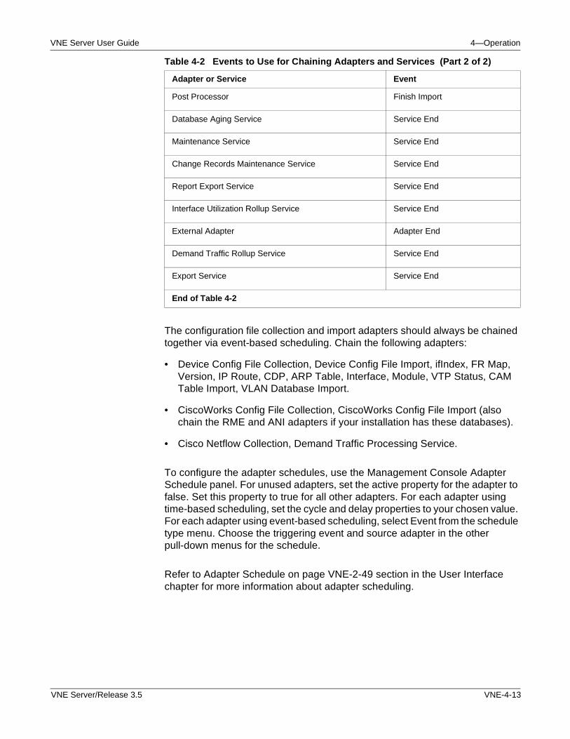
VNE Server User Guide 4—Operation
The configuration file collection and import adapters should always be chained together via event-based scheduling. Chain the following adapters:
• Device Config File Collection, Device Config File Import, ifIndex, FR Map, Version, IP Route, CDP, ARP Table, Interface, Module, VTP Status, CAM Table Import, VLAN Database Import.
• CiscoWorks Config File Collection, CiscoWorks Config File Import (also chain the RME and ANI adapters if your installation has these databases).
• Cisco Netflow Collection, Demand Traffic Processing Service.
To configure the adapter schedules, use the Management Console Adapter Schedule panel. For unused adapters, set the active property for the adapter to false. Set this property to true for all other adapters. For each adapter using time-based scheduling, set the cycle and delay properties to your chosen value. For each adapter using event-based scheduling, select Event from the schedule type menu. Choose the triggering event and source adapter in the other pull-down menus for the schedule.
Refer to Adapter Schedule on page VNE-2-49 section in the User Interface chapter for more information about adapter scheduling.
Post Processor Finish Import
Database Aging Service Service End
Maintenance Service Service End
Change Records Maintenance Service Service End
Report Export Service Service End
Interface Utilization Rollup Service Service End
External Adapter Adapter End
Demand Traffic Rollup Service Service End
Export Service Service End
End of Table 4-2
Table 4-2 Events to Use for Chaining Adapters and Services (Part 2 of 2)
Adapter or Service Event
VNE Server/Release 3.5 VNE-4-13
4—Operation VNE Server User Guide
Continuous Operation
Once configuration activities are complete, you are ready to transition VNE Server to continuous operation. The following sections describe how to start data collection and monitor operation using the Control Panel, Console, Event Viewer, Report Manager, and Network Browser.
Using the VNE Server Control Panel to Start and Monitor Data Collection
The VNE Server Control Panel is used to start data collection and to monitor system events during initial data collection, while the Console is used to verify that all the enabled adapters activate and that no problems exist with data collection. For more information about the VNE Server Control Panel, refer to Control Panel on page VNE-2-5 section in the User Interface chapter.
Starting Data Collection for the First Time
During the configuration process, the network database was populated with test data. Before running VNE Server in an operational mode, delete the test database by performing the following steps.
1) Stop VNE Server services, if they are running.
2) Use the VNE Server Control Panel > Tools menu to remove temp dir and empty current project.
3) Restart VNE Server using the procedure Starting VNE Server on page VNE-2-2 in the User Interface chapter.
To monitor VNE Server more closely during initial data collection, switch the Console to Detail View mode so you can monitor adapter execution. Open a Live Event Log Viewer so start-up events are visible.
Start VNE Server data collection using the procedure Starting VNE Server Services on page VNE-2-8 in the User Interface chapter.
When services start, a Progress Status box opens and displays start-up progress information. After adapters are triggered to run, the Console shows adapters operating, and the Event Viewer shows adapter events.
If you need to stop data collection, refer to Stopping VNE Server Services on page VNE-2-8 in the User Interfacechapter. Note that when you stop data collection, any data in the network database is retained. You can restart data collection at any time.
VNE-4-14 VNE Server/Release 3.5
VNE Server User Guide 4—Operation
Monitoring Data Collection
After you start data collection, closely monitor the progress of initial data collection. Continue to monitor adapter activity throughout the remainder of the first data collection pass. Use the Console System Status panel to verify adapters are running as intended.
• Verify that each adapter and service runs when scheduled.
• Verify that adapter and service operation is mostly sequential.
• Verify that VNE-XML Import is processing and importing data.
As system events begin to appear in the Event Viewer, verify that
• Few device access errors occur
• Third-party NMS products are successfully accessed
• No Emergency or Critical events occur
Throughout VNE Server operation, use the Adapter Statistics view to examine adapter execution statistics. To open Adapter Statistics, select View > Adapter Statistics from the Console menu bar. Using Adapter Statistics, verify that
• All adapters are running
• Devices are accessed successfully
• Files are collected from third-party NMS products
• Links are created
Determine proper operation of VNE Server by monitoring system events and by using the Report Manager and Network Browser. These same tools can be used at any time to verify that VNE Server is operating as intended or to view information about the network.
VNE Server/Release 3.5 VNE-4-15
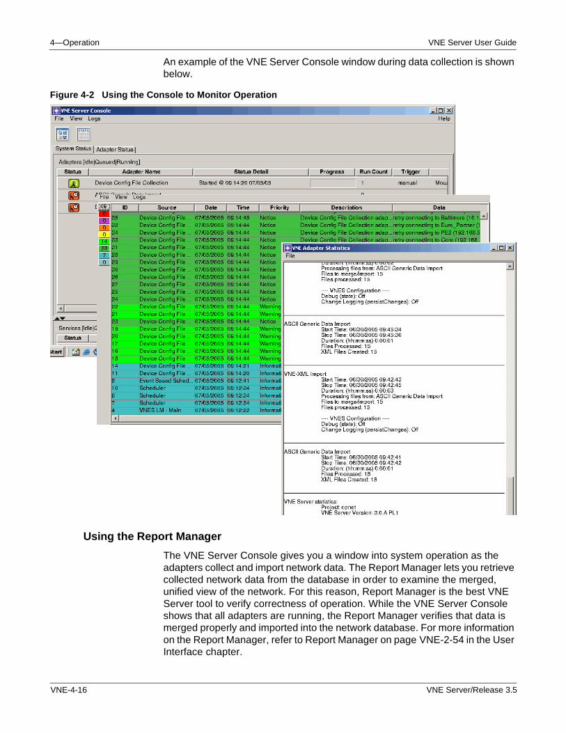
4—Operation VNE Server User Guide
An example of the VNE Server Console window during data collection is shown below.
Figure 4-2 Using the Console to Monitor Operation
Using the Report Manager
The VNE Server Console gives you a window into system operation as the adapters collect and import network data. The Report Manager lets you retrieve collected network data from the database in order to examine the merged, unified view of the network. For this reason, Report Manager is the best VNE Server tool to verify correctness of operation. While the VNE Server Console shows that all adapters are running, the Report Manager verifies that data is merged properly and imported into the network database. For more information on the Report Manager, refer to Report Manager on page VNE-2-54 in the User Interface chapter.
VNE-4-16 VNE Server/Release 3.5
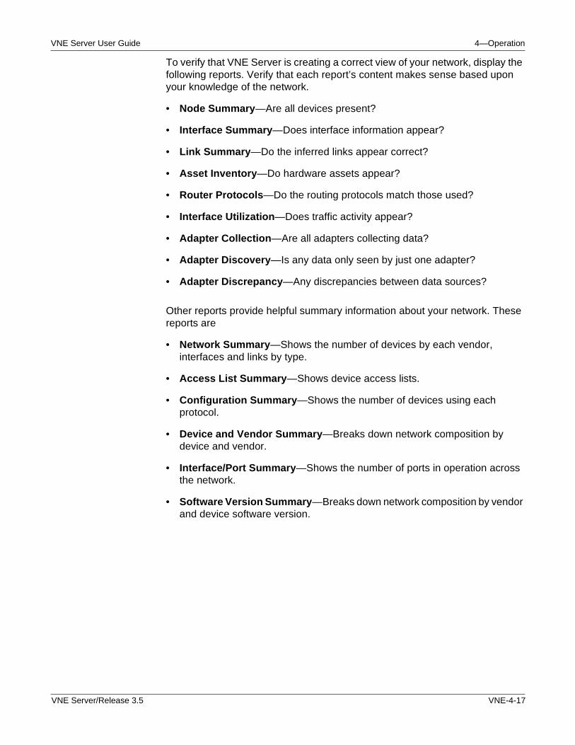
VNE Server User Guide 4—Operation
To verify that VNE Server is creating a correct view of your network, display the following reports. Verify that each report’s content makes sense based upon your knowledge of the network.
• Node Summary—Are all devices present?
• Interface Summary—Does interface information appear?
• Link Summary—Do the inferred links appear correct?
• Asset Inventory—Do hardware assets appear?
• Router Protocols—Do the routing protocols match those used?
• Interface Utilization—Does traffic activity appear?
• Adapter Collection—Are all adapters collecting data?
• Adapter Discovery—Is any data only seen by just one adapter?
• Adapter Discrepancy—Any discrepancies between data sources?
Other reports provide helpful summary information about your network. These reports are
• Network Summary—Shows the number of devices by each vendor, interfaces and links by type.
• Access List Summary—Shows device access lists.
• Configuration Summary—Shows the number of devices using each protocol.
• Device and Vendor Summary—Breaks down network composition by device and vendor.
• Interface/Port Summary—Shows the number of ports in operation across the network.
• Software Version Summary—Breaks down network composition by vendor and device software version.
VNE Server/Release 3.5 VNE-4-17
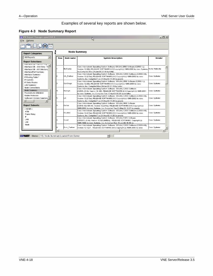
4—Operation VNE Server User Guide
Examples of several key reports are shown below.
Figure 4-3 Node Summary Report
VNE-4-18 VNE Server/Release 3.5
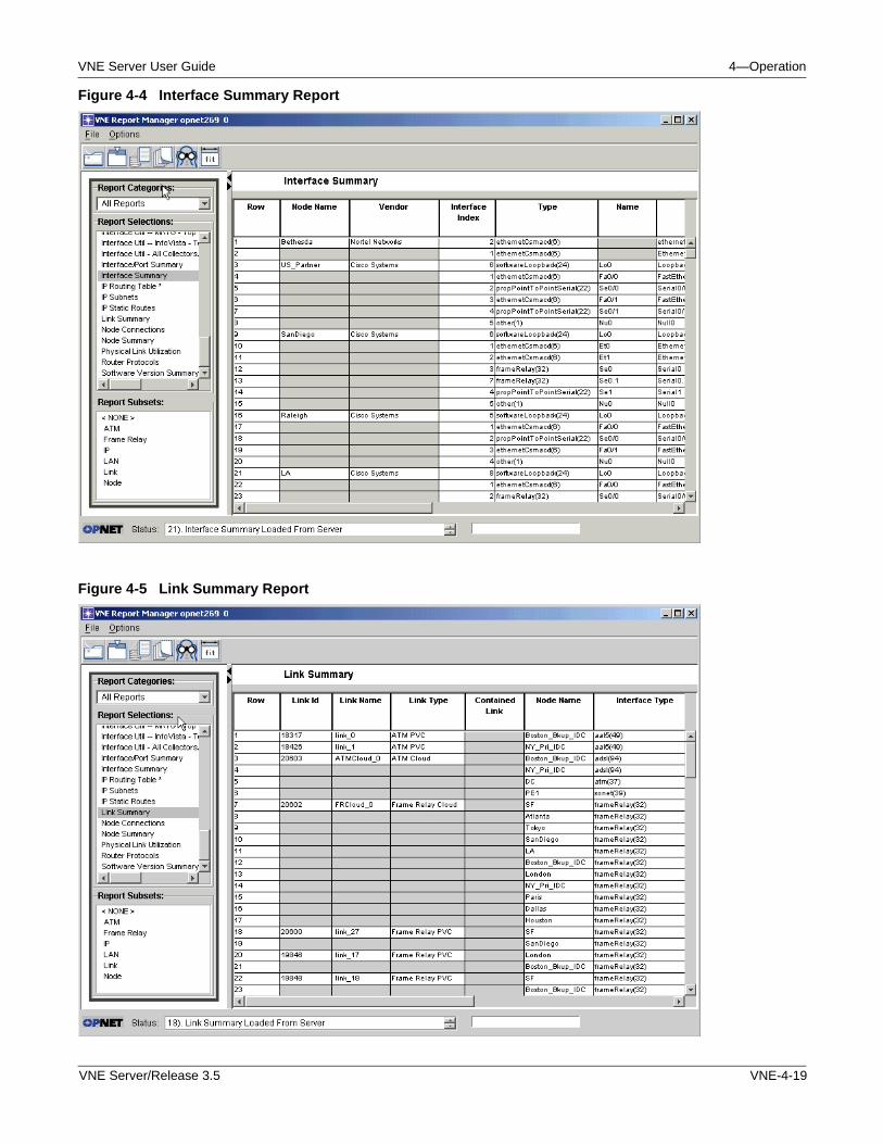
VNE Server User Guide 4—Operation
Figure 4-4 Interface Summary Report
Figure 4-5 Link Summary Report
VNE Server/Release 3.5 VNE-4-19
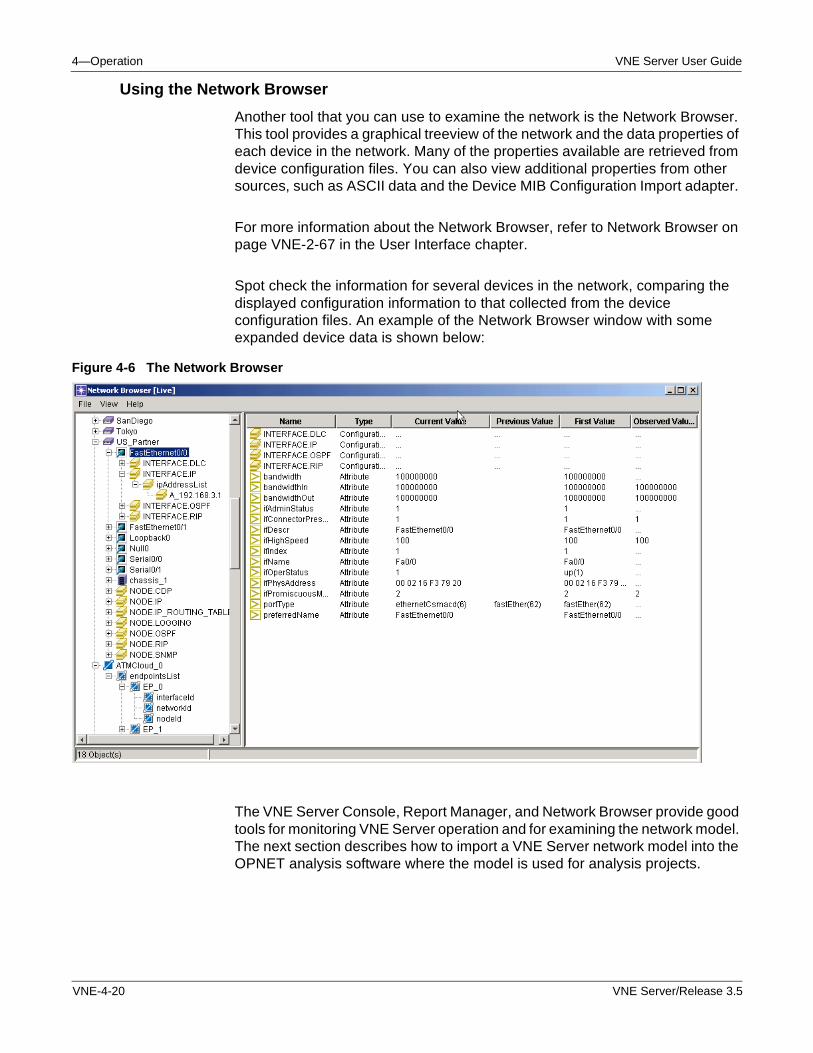
4—Operation VNE Server User Guide
Using the Network Browser
Another tool that you can use to examine the network is the Network Browser. This tool provides a graphical treeview of the network and the data properties of each device in the network. Many of the properties available are retrieved from device configuration files. You can also view additional properties from other sources, such as ASCII data and the Device MIB Configuration Import adapter.
For more information about the Network Browser, refer to Network Browser on page VNE-2-67 in the User Interface chapter.
Spot check the information for several devices in the network, comparing the displayed configuration information to that collected from the device configuration files. An example of the Network Browser window with some expanded device data is shown below:
Figure 4-6 The Network Browser
The VNE Server Console, Report Manager, and Network Browser provide good tools for monitoring VNE Server operation and for examining the network model. The next section describes how to import a VNE Server network model into the OPNET analysis software where the model is used for analysis projects.
VNE-4-20 VNE Server/Release 3.5
VNE Server User Guide 5—Administration
5 Administration
Introduction
This chapter describes the VNE Server environment and common administrative tasks. VNE Server does not require extensive administration. However, you need a basic understanding of the installation and temporary directory environment for effective troubleshooting and administration. Since VNE Server relies upon an Oracle database, some basic knowledge of Oracle administration is also presented in this chapter.
VNE Server Administration
This section describes the VNE Server installation and temporary directory environment. Administrative procedures in the following areas are also covered.
• Managing projects
• Reconfiguring VNE Server
• Managing logs and traffic data
• Software upgrades
• License operations
• Configuring OPNET analysis software
Windows Services
VNE Server processes run as Windows services. This means that VNE Server no longer needs to be run by a logged-in user. It may continue to run in the background even after the user logs off. After the machine is rebooted, VNE Server will automatically launch and start VNE Server services. If the schedule has been configured so that an event chain is initiated by a time-scheduled adapter, this will occur as normal.
Note—We strongly recommend that you configure Windows Automatic Update service on the VNE Server host to notify you when updates are ready to install rather than permitting updates to be installed automatically. When Windows Automatic Update service installs updates automatically, the update service may reboot the machine following the update and interrupt VNE Server operation.
The Windows services installed by VNE Server are
• OPNET VNES Adapter Server
VNE Server/Release 3.5 VNE-5-1
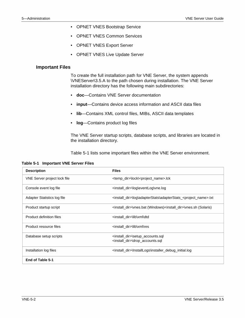
5—Administration VNE Server User Guide
• OPNET VNES Bootstrap Service
• OPNET VNES Common Services
• OPNET VNES Export Server
• OPNET VNES Live Update Server
Important Files
To create the full installation path for VNE Server, the system appends \VNEServer\3.5.A to the path chosen during installation. The VNE Server installation directory has the following main subdirectories:
• doc—Contains VNE Server documentation
• input—Contains device access information and ASCII data files
• lib—Contains XML control files, MIBs, ASCII data templates
• log—Contains product log files
The VNE Server startup scripts, database scripts, and libraries are located in the installation directory.
Table 5-1 lists some important files within the VNE Server environment.
Table 5-1 Important VNE Server Files
Description Files
VNE Server project lock file <temp_dir>\lock\<project_name>.lck
Console event log file <install_dir>\log\eventLog\vne.log
Adapter Statistics log file <install_dir>\log\adapterStats\adapterStats_<project_name>.txt
Product startup script <install_dir>\vnes.bat (Windows)<install_dir>\vnes.sh (Solaris)
Product definition files <install_dir>\lib\xml\dtd
Product resource files <install_dir>\lib\xml\res
Database setup scripts <install_dir>\setup_accounts.sql<install_dir>\drop_accounts.sql
Installation log files <install_dir>\InstallLogs\installer_debug_initial.log
End of Table 5-1
VNE-5-2 VNE Server/Release 3.5
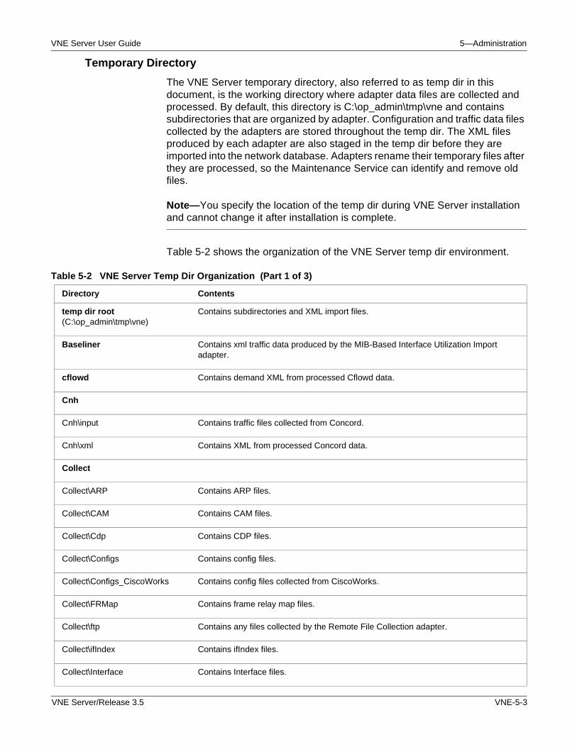
VNE Server User Guide 5—Administration
Temporary Directory
The VNE Server temporary directory, also referred to as temp dir in this document, is the working directory where adapter data files are collected and processed. By default, this directory is C:\op_admin\tmp\vne and contains subdirectories that are organized by adapter. Configuration and traffic data files collected by the adapters are stored throughout the temp dir. The XML files produced by each adapter are also staged in the temp dir before they are imported into the network database. Adapters rename their temporary files after they are processed, so the Maintenance Service can identify and remove old files.
Note—You specify the location of the temp dir during VNE Server installation and cannot change it after installation is complete.
Table 5-2 shows the organization of the VNE Server temp dir environment.
Table 5-2 VNE Server Temp Dir Organization (Part 1 of 3)
Directory Contents
temp dir root (C:\op_admin\tmp\vne)
Contains subdirectories and XML import files.
Baseliner Contains xml traffic data produced by the MIB-Based Interface Utilization Import adapter.
cflowd Contains demand XML from processed Cflowd data.
Cnh
Cnh\input Contains traffic files collected from Concord.
Cnh\xml Contains XML from processed Concord data.
Collect
Collect\ARP Contains ARP files.
Collect\CAM Contains CAM files.
Collect\Cdp Contains CDP files.
Collect\Configs Contains config files.
Collect\Configs_CiscoWorks Contains config files collected from CiscoWorks.
Collect\FRMap Contains frame relay map files.
Collect\ftp Contains any files collected by the Remote File Collection adapter.
Collect\ifIndex Contains ifIndex files.
Collect\Interface Contains Interface files.
VNE Server/Release 3.5 VNE-5-3
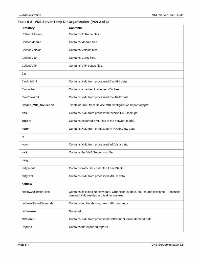
5—Administration VNE Server User Guide
Collect\IPRoute Contains IP Route files.
Collect\Module Contains Module files.
Collect\Version Contains Version files.
Collect\Vlan Contains VLAN files.
Collect\VTP Contains VTP status files.
Cw
Cw\Ani\Xml Contains XML from processed CW ANI data.
Cw\cache Contains a cache of collected CW files.
Cw\Rme\Xml Contains XML from processed CW RME data.
Device_MIB_Collection Contains XML from Device MIB Configuration Import adapter.
dns Contains XML from processed reverse DNS lookups.
export Contains exported XML files of the network model.
hpov Contains XML from processed HP OpenView data.
iv
iv\xml Contains XML from processed InfoVista data.
lock Contains the VNE Server lock file.
mrtg
mrtg\input Contains traffic files collected from MRTG.
mrtg\xml Contains XML from processed MRTG data.
netflow
netflow\collectedFiles Contains collected Netflow data. Organized by date, source and flow type. Processed demand XML resides in this directory tree.
netflow\filteredDemands Contains log file showing low traffic demands.
netflow\xml Not used.
NetScout Contains XML from processed NetScout nGenius demand data.
Reports Contains the exported reports.
Table 5-2 VNE Server Temp Dir Organization (Part 2 of 3)
Directory Contents
VNE-5-4 VNE Server/Release 3.5
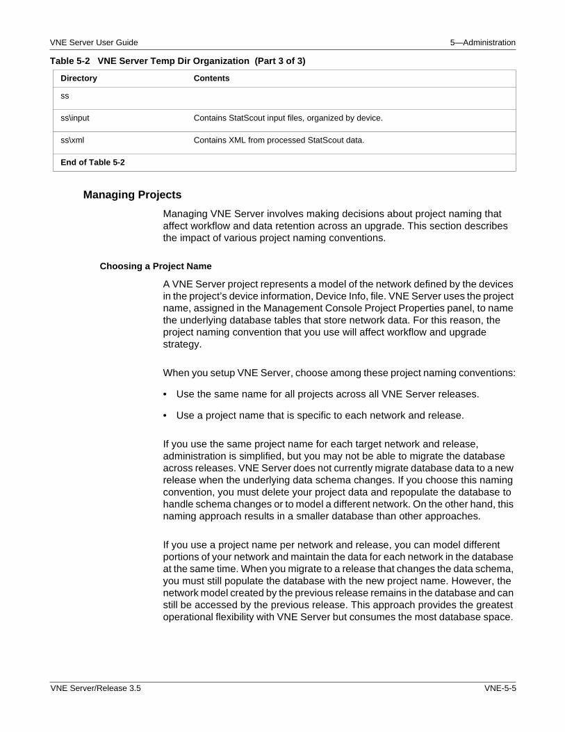
VNE Server User Guide 5—Administration
Managing Projects
Managing VNE Server involves making decisions about project naming that affect workflow and data retention across an upgrade. This section describes the impact of various project naming conventions.
Choosing a Project Name
A VNE Server project represents a model of the network defined by the devices in the project’s device information, Device Info, file. VNE Server uses the project name, assigned in the Management Console Project Properties panel, to name the underlying database tables that store network data. For this reason, the project naming convention that you use will affect workflow and upgrade strategy.
When you setup VNE Server, choose among these project naming conventions:
• Use the same name for all projects across all VNE Server releases.
• Use a project name that is specific to each network and release.
If you use the same project name for each target network and release, administration is simplified, but you may not be able to migrate the database across releases. VNE Server does not currently migrate database data to a new release when the underlying data schema changes. If you choose this naming convention, you must delete your project data and repopulate the database to handle schema changes or to model a different network. On the other hand, this naming approach results in a smaller database than other approaches.
If you use a project name per network and release, you can model different portions of your network and maintain the data for each network in the database at the same time. When you migrate to a release that changes the data schema, you must still populate the database with the new project name. However, the network model created by the previous release remains in the database and can still be accessed by the previous release. This approach provides the greatest operational flexibility with VNE Server but consumes the most database space.
ss
ss\input Contains StatScout input files, organized by device.
ss\xml Contains XML from processed StatScout data.
End of Table 5-2
Table 5-2 VNE Server Temp Dir Organization (Part 3 of 3)
Directory Contents
VNE Server/Release 3.5 VNE-5-5
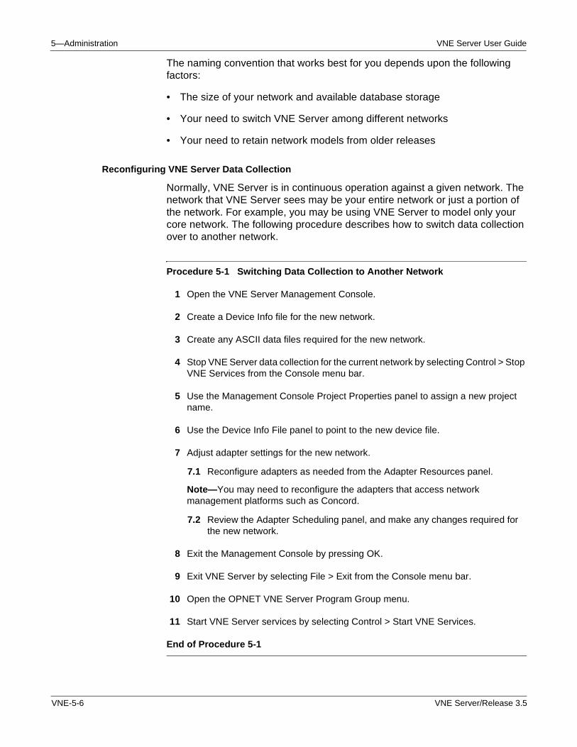
5—Administration VNE Server User Guide
The naming convention that works best for you depends upon the following factors:
• The size of your network and available database storage
• Your need to switch VNE Server among different networks
• Your need to retain network models from older releases
Reconfiguring VNE Server Data Collection
Normally, VNE Server is in continuous operation against a given network. The network that VNE Server sees may be your entire network or just a portion of the network. For example, you may be using VNE Server to model only your core network. The following procedure describes how to switch data collection over to another network.
Procedure 5-1 Switching Data Collection to Another Network
1 Open the VNE Server Management Console.
2 Create a Device Info file for the new network.
3 Create any ASCII data files required for the new network.
4 Stop VNE Server data collection for the current network by selecting Control > Stop VNE Services from the Console menu bar.
5 Use the Management Console Project Properties panel to assign a new project name.
6 Use the Device Info File panel to point to the new device file.
7 Adjust adapter settings for the new network.
7.1 Reconfigure adapters as needed from the Adapter Resources panel.
Note—You may need to reconfigure the adapters that access network management platforms such as Concord.
7.2 Review the Adapter Scheduling panel, and make any changes required for the new network.
8 Exit the Management Console by pressing OK.
9 Exit VNE Server by selecting File > Exit from the Console menu bar.
10 Open the OPNET VNE Server Program Group menu.
11 Start VNE Server services by selecting Control > Start VNE Services.
End of Procedure 5-1
VNE-5-6 VNE Server/Release 3.5
VNE Server User Guide 5—Administration
Monitor data collection and evaluate the resulting network model as described in the Operation chapter.
Managing Logs and Traffic Data
During operation, VNE Server produces log files that contain Console events and internal system activity. These files can consume hundreds of megabytes of disk space. If you are using VNE Server to collect interface utilization data, the traffic data that is written to the database can also require a significant amount of storage. This section describes the tools that VNE Server provides for managing logs and traffic data.
Managing Log File Growth
VNE Server provides the following types of logs:
• Console event logs that are located at: <install dir>\log\eventlog
• Services logs that are located at: <install dir>\log
The events displayed by the VNE Server Console are stored in multiple log files. The log file that contains events currently displayed in the console is named vne.log. Once the maximum event display count is reached in the Console, this file is capped, renamed to a vne_<date_time>.old.log file name, and a new vne.log file is opened.
The services logs provide any warnings, failures, errors, or exceptions that occur during VNE Server operation. The services log files are named:
• Control_Panel.log
• OPNETVNESAdapterServer.log
• OPNETVNESBootstrapService.log
• OPNETVNESCommonServices.log
• OPNETVNESExportServer.log
• OPNETVNESLiveUpdateServer.log
• VNE_REPORT.log
The size of each log file is capped at a default size of 10 MBytes. When a log file grows to this size, it is renamed to <log_file_name>.archive.<timestamp>, and a new file is started. By default, a maximum of 10 of each of the services log files are retained. After the maximum number of log files is reached, the oldest file is deleted.
VNE Server/Release 3.5 VNE-5-7
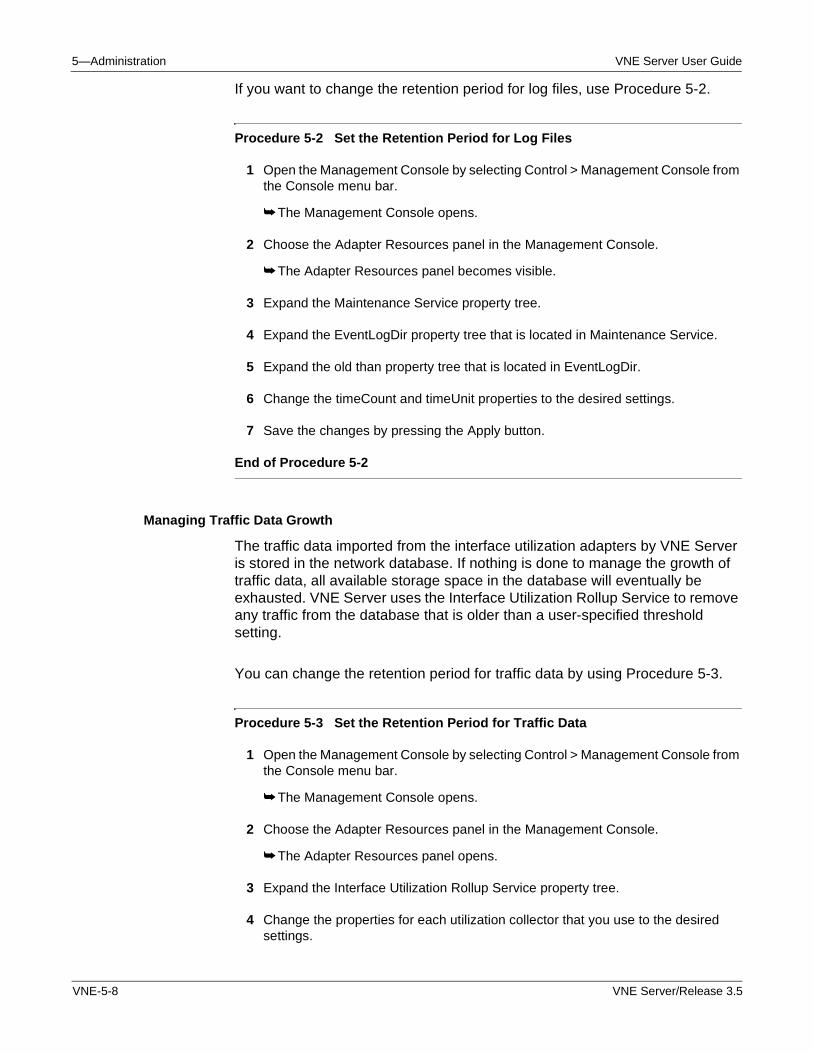
5—Administration VNE Server User Guide
If you want to change the retention period for log files, use Procedure 5-2.
Procedure 5-2 Set the Retention Period for Log Files
1 Open the Management Console by selecting Control > Management Console from the Console menu bar.
➥ The Management Console opens.
2 Choose the Adapter Resources panel in the Management Console.
➥ The Adapter Resources panel becomes visible.
3 Expand the Maintenance Service property tree.
4 Expand the EventLogDir property tree that is located in Maintenance Service.
5 Expand the old than property tree that is located in EventLogDir.
6 Change the timeCount and timeUnit properties to the desired settings.
7 Save the changes by pressing the Apply button.
End of Procedure 5-2
Managing Traffic Data Growth
The traffic data imported from the interface utilization adapters by VNE Server is stored in the network database. If nothing is done to manage the growth of traffic data, all available storage space in the database will eventually be exhausted. VNE Server uses the Interface Utilization Rollup Service to remove any traffic from the database that is older than a user-specified threshold setting.
You can change the retention period for traffic data by using Procedure 5-3.
Procedure 5-3 Set the Retention Period for Traffic Data
1 Open the Management Console by selecting Control > Management Console from the Console menu bar.
➥ The Management Console opens.
2 Choose the Adapter Resources panel in the Management Console.
➥ The Adapter Resources panel opens.
3 Expand the Interface Utilization Rollup Service property tree.
4 Change the properties for each utilization collector that you use to the desired settings.
VNE-5-8 VNE Server/Release 3.5
VNE Server User Guide 5—Administration
5 Save the changes by pressing the Apply button.
End of Procedure 5-3
Exporting Reports to Files
The preferred way to export reports is through the Report Export Service. The Report Export Service is used for scheduled export of reports. In addition, VNE Server provides a script, export_reports.bat, that exports all reports to files. You can run this script while VNE services are operating. Use Procedure 5-4 to export reports to files.
Procedure 5-4 Export Reports to Files
1 Open a command prompt window, and navigate to the VNE Server installation directory by typing
cd <install path>\VNEServer\3.5.A
2 Run the export script.
• If you use Oracle8i, type
export_reports.bat -o <output directory path> -e <report format>
• If you use Oracle9i, type
export_reports.bat /Oracle9i -o <output directory path> -e <report format>
Where <output directory path> is the location to which report files are written, and <report format> is
• 0 for HTML formatted report files
• 1 for XML formatted report files
• 2 for CSV formatted report files
• 3 for ASCII formatted report files
➥ Progress messages appear in the command window. When export is complete, a “Completed exporting...” message appears.
End of Procedure 5-4
VNE Server provides a script, run_report.bat, that exports a selected report to file. You can run this script while VNE services are operating using Procedure 5-5.
Procedure 5-5 Export a Selected Report to File
1 Open a command prompt window and navigate to the VNE Server installation directory by typing
VNE Server/Release 3.5 VNE-5-9
5—Administration VNE Server User Guide
cd <install path>\VNEServer\3.5.A
2 To get a list of report IDs, type
run_report.bat -l
➥ A list of report names and their ID numbers is displayed in the command window. Note the ID number of the report you want to export.
3 Run the export script.
• If you use Oracle8i, type:
run_report.bat -f <output filename> -r <report id> -e <report format>
• If you use Oracle9i, type:
run_report.bat /Oracle9i -f <output filename> -r <report id> -e <report format>
Where <output filename> is the file to which the report is written, and <report ID> is the ID number of the report you want to export, and <report format> is
• 0 for HTML formatted report files
• 1 for XML formatted report files
• 2 for CSV formatted report files
• 3 for ASCII formatted report files
➥ Progress messages appear in the command window. When export is complete, a “Completed exporting...” message appears.
End of Procedure 5-5
Software Upgrades
VNE Server releases use a major release, minor release naming convention that is reflected in the installation path name. A major release denotes significant new features or framework enhancements in the product. A minor release contains incremental improvements and bug fixes.
The product installer appends VNEServer\<major release> to the chosen installation path. For example, if C:\OPNET is the chosen installation path for the 3.5.A release, the complete path is C:\OPNET\VNEServer\3.5.A. Minor releases are called patch levels and are denoted as PL1, PL2, and so on.
The general workflow when doing a software upgrade for VNE Server consists of the following steps.
1) Stop data collection, and exit the existing VNE Server installation.
2) If you have a local license server running, execute Procedure 5-7 to stop the server. the following procedures, based upon your platform, to stop the server.
VNE-5-10 VNE Server/Release 3.5
VNE Server User Guide 5—Administration
• Windows: Procedure 5-7
• Solaris: Procedure 5-9
3) If upgrading to a new build in the same release, rename the existing installation directory to preserve the current release. For example, rename a 3.5 PL1 release to 3.5.1_<bld#>.
4) Install the new VNE Server release.
5) Migrate the Device Info and ASCII data files to the new installation.
6) Change the project name to something that reflects the network.
7) Configure the adapters for the newly installed release.
8) Start data collection in the newly installed release.
Note—At this time, VNE Server does not migrate database data schema or adapter configuration data from one release to another.
WARNING—Always follow the installation instructions in the Installation Card and the Release Notes for a new release. The general workflow described in this section may not match the workflow for a specific release.
Oracle Performance Enhancement
The setup accounts script (@setup_accounts.sql) that you use to configure the database following installation of VNE Server 3.5 was enhanced to analyze Oracle 9i memory-related database parameters and recommend changes, when applicable, to improve VNE Server performance. The parameters that are examined are the Oracle SGA_MAX SIZE and DB_CACHE_SIZE parameters. After the setup accounts script completes, a recommendation may be made to run a database parameters change script (@dbparamchg.sql) to modify these parameters.
Note—Consult with your Oracle database administrator before making changes to the Oracle database.
Note—Ensure that there is at least 500 MB of physical memory available on the Oracle server host before making these changes.
VNE Server/Release 3.5 VNE-5-11
5—Administration VNE Server User Guide
If you choose to run the database parameters change script, the changes will apply to the database instance into which you are logged in when you run the setup accounts script.The database parameters change script increases the SGA_MAX SIZE from ~130 MB to ~560 MB and the DB_CACHE_SIZE from ~25 MB to ~85 MB. These changes increase the amount of memory used by Oracle and improve data import performance for large networks. The most significant performance changes are noted for import of data on very large networks (greater than 100,000 interfaces).
Refer to the sections on Configuring the Oracle Database and Modifying Database Parameters in the VNE Server 3.5 Windows Installation card for additional information and instructions.
Product Licensing
VNE Server releases 3.0 and higher require the OPNET 11.0 license server and a license in the 11.0 format. VNE Server supports the following license scenarios:
• Remote: obtain a license from a license server on a remote host.
• Local: obtain a license from a license server on the VNE Server host.
Licenses for VNE Server can be administered from any OPNET License Manager running on remote hosts that can communicate with the VNE Server host. Licenses can also be administered from a license manager running on the same host as VNE Server.
Deployment Scenarios
When you install VNE Server, you must choose whether to obtain licenses from a local or remote license server. Some reasons to choose to obtain licenses from a remote license server are
• Leverage an existing license server within your organization
• Use a GUI-based License Manager application to manage licenses
• The VNE Server host and license server host can communicate
Some reasons to chose to obtain licenses from a local license server are
• VNE Server host cannot see a remote license server due to firewalls
• More robust licensing to support 24x7 VNE Server operation
VNE-5-12 VNE Server/Release 3.5
VNE Server User Guide 5—Administration
If you choose to work with a remote license server, the GUI-based License Manager is more convenient to use than the command line license manager deployed with the local license server, installed with VNE Server. Since VNE Server is intended for use as a 24x7 application, persisting network problems or host downtime with the remote license server can cause VNE Server to shut down, if problems are not resolved within the license grace period.
if you choose to work with a local license server, 24x7 operations are more robust since license operations are all local. Network problems cannot affect license operations. If the VNE Server host is separated from other license servers by a firewall, you must use the command line license manager utility for all license management. If the VNE Server host can see another host running OPNET analysis software, the GUI-based License Manager on those hosts can manage licenses maintained by the license server on the VNE Server host.
If a license server already exists on the VNE Server host as a part of a previous OPNET analysis software installation, and you wish to use this local license server for VNE Server, install VNE Server to use a “remote” license server. During VNE Server installation, do the following:
• Enter the hostname of the local host as the license server host.
• Enter the port (a,b,c) used by the local license server.
License Administration
VNE Server provides a command line license server utility (LS_UTIL) for performing license operations using the Browser Method. If you prefer, you may use the License Manager user interface that is provided with OPNET 11.0 software; given that OPNET 11.0 is installed on a machine on the same IP network as your VNE Server host, and there are no access restrictions between the two machines.
The OPNET License Manager application provides the most convenient means to monitor and manage VNE Server licenses. The License Manager provides a GUI to support license operations. The OPNET Administrator Guide describes how to use the License Manager. When a local license server is installed with VNE Server, a command line license management application is provided for managing licenses. You only need to use this command line license manager if you do not have a GUI based License Manager anywhere in your environment that can see the local license server.
VNE Server/Release 3.5 VNE-5-13
5—Administration VNE Server User Guide
Instructions for adding a license and converting a pre-11.0 license file using the OPNET License Manager are provided on the License Registration page of the OPNET support website. You may also perform these actions using VNE Server’s command line licensing utility (LS_UTIL) as described in Procedure 5-6.
Procedure 5-6 Converting a pre-11.0 License File Using License Manager
1 Make sure VNE Server is not running. If it is, stop VNE Server services and exit VNE Server completely.
2 Open a DOS Prompt/Console window, and navigate to the VNE Server installation directory.
3 Enter the following command and note the name of the computer, paying attention to case:
hostname
4 Start the license manager utility (LS_UTIL) on the computer where you want to add the license. The command to run the License Manager is
vnes.bat /<oracle_version> /lic_host <hostname> /lic_port <port> LS_UTIL
where: <oracle_version> is either Oracle8i or Oracle9i<hostname> is the hostname of the license server<port> is the port for the license server (default value is port_a)
5 At the manager> prompt, enter:
convert11_db
➥ Make note of the Transaction code that displays.
Note—IMPORTANT: Leave this session open until you receive the approval code from OPNET.
6 Open the OPNET Licensing Web Page, using the Start Menu on Windows.
7 Click on the link to Perform license operations.
8 Choose the License Operation you wish to complete. Make sure Convert Pre-11.0 License File is selected, then click Next.
9 Enter the transaction code from the VNE Server license manager utility by copying it from the console window and pasting it into the browser window.
10 Enter the hostname of the computer on which you are installing the license (case-sensitive). Click the Next button.
11 Choose the license you wish to convert.
12 Confirm that all of the information is correct in the License Operation Confirmation panel. After you have confirmed the information is correct, click on the Get Approval Code button.
VNE-5-14 VNE Server/Release 3.5
VNE Server User Guide 5—Administration
The approval code will be in the following form: 38D5.557B.215B.1AC7.05AD.1D95.C68B.F8F3.150E.52BF.4872.5BB2.CCC1.CB67.D6BE.53CB.FCC0.D663
13 Copy the approval code from the browser window and paste it into the console window (at the waiting LS_UTIL manager> prompt), and press the Enter key on your keyboard.
➥ You should now see a message indicating the license operation succeeded.
14 In the browser window, click Next.
15 Close the browser window.
16 In the console, enter the following command into LS_UTIL
permit
➥ You should now see the license that you converted.
17 Enter quit to exit the license utility.
End of Procedure 5-6
Restrictions and Limitations
VNE Server has the following restrictions regarding product licensing.
• The license server used by VNE Server must be from the OPNET 10.5.A release or higher.
• Standalone licensing is not supported by VNE Server.
• Loanable licenses are not supported for VNE Server.
• Only one local license server can be installed on the VNE Server host.
• The license manager utility (LS_UTIL) included with VNE Server does not support Express Method license operations.
• A license server installed with VNE Server on a host with no OPNET analysis software installed will default to listen on port_a.
• A license server installed with VNE Server on a host with OPNET analysis software installed (configured for remote licensing) will use the port specified in the licensing.ef file in the OPNET analysis software installation at \sys\configs\global_prefs.
Licensing Resources
The following resources provide more information about OPNET licensing.
• The OPNET Administrator Guide (OPNET documentation package).
• The OPNET License Registration web page at
VNE Server/Release 3.5 VNE-5-15
5—Administration VNE Server User Guide
http://ds1.opnet.com/4dcgi/licw4d_cl_content.
Command Line Utilities
VNE Server provides the following command line utilities for license related work.
• LS—Starts a local license server
• LS_KILL—Stops a local license server
• LS_UTIL—A command line license manager utility
When using these command line utilities, the /lic_host and /lic_port options MUST be used in the vnes.bat command line on a Windows system. For Solaris systems, the required options are -l (host) and -p (port).
The full command line for each utility on a Windows system is shown.
• vnes.bat /Oracle9i /lic_host <license server host> /lic_port <port> LS
• vnes.bat /Oracle9i /lic_host <license server host> /lic_port <port> LS_KILL
• vnes.bat /Oracle9i /lic_host <license server host> /lic_port <port> LS_UTIL
Where <license server host> is replaced with the hostname of the system running the license server used to obtain a license.
Where <port> is the communication port used by the license server. Valid entries are port_a, port_b or port_c.
Note—If you are using an Oracle8i database, the /Oracle9i switch is omitted from the commands listed above.
The full command line for each utility on a Solaris system is shown.
• vnes.sh -r Oracle9i -l <license server host> -p <port> LS
• vnes.sh -r Oracle9i -l <license server host> -p <port> LS_KILL
• vnes.sh -r Oracle9i -l <license server host> -p <port> LS_UTIL
VNE-5-16 VNE Server/Release 3.5
VNE Server User Guide 5—Administration
Licensing Operations
The following procedures describe common licensing operations.
Procedure 5-7 Starting and Stopping a Local License Server using Windows Service Manager
1 Open the Windows Service manager.
Open Start > Settings > Control Panel > Administrative Tools > Services
2 In the Services window, scroll down and choose the OPNET License Server.
3 Start or stop the server, as needed.
3.1 To start the server, right-click on OPNET License Server, and select Start from the menu.
➥ The OPNET License Server status changes to “Started”.
3.2 To stop the server, right-click on OPNET License Server, and select Stop from the menu.
➥ The OPNET License Server stops. The service status field is cleared.
End of Procedure 5-7
Procedure 5-8 Starting a Local License Server using Command Line Utilities
1 Open a command window and “cd” to the VNE Server installation directory.
2 Type: hostname
➥ Note the hostname displayed by this command. It is used (exact case match) with the /lic_host (or -l) option in the following command.
3 Start the license server.
• On a Windows system using Oracle9i, type:
vnes.bat /Oracle9i /lic_host <local hostname> /lic_port <server port> LS
• On a Windows system using Oracle8i, type:
vnes.bat /lic_host <local hostname> /lic_port <server port> LS
• On a Solaris system, type:
vnes.sh -r Oracle9i -l <local hostname> -p <server port> LS
For the /lic_port (-p on Solaris) option, specify the port used by this server. It will be one of port_a, port_b, port_c.
End of Procedure 5-8
VNE Server/Release 3.5 VNE-5-17
5—Administration VNE Server User Guide
Procedure 5-9 Stopping a Local License Server using Command Line Utilities
1 Open a command window and “cd” to the VNE Server installation directory.
2 Type: hostname
➥ Note the hostname displayed by this command. It is used (exact case match) with the /lic_host option in the following command.
3 Stop the license server.
• On a Windows system using Oracle9i, type
vnes.bat /Oracle9i /lic_host <local hostname> /lic_port <server port> LS_KILL
• On a Windows system using Oracle8i, type
vnes.bat /lic_host <local hostname> /lic_port <server port> LS_KILL
• On a Solaris system, type
vnes.sh -r Oracle9i -l <local hostname> -p <server port> LS_KILL
For the /lic_port (-p on Solaris) option, specify the port used by this server. It will be one of port_a, port_b, port_c.
➥ A “Success: license server stopped” message appears on the command line.
End of Procedure 5-9
Procedure 5-10 Changing the Settings used to Communicate with a Remote License Server
Note—Use this procedure to change the host or port settings for the remote license server used by VNE Server to obtain a license.
1 If VNE Server is operating, stop services and exit the Console.
2 Open a command window and “cd” to the VNE Server installation directory.
3 Enter the license manager utility.
• On a Windows system using Oracle9i, type
vnes.bat /Oracle9i /lic_host <hostname> /lic_port <server port> LS_UTIL
• On a Windows system using Oracle8i, type
vnes.bat /lic_host <hostname> /lic_port <server port> LS_UTIL
• On a Solaris system, type
vnes.sh -r Oracle9i -l <local hostname> -p <server port> LS_UTIL
For the host option, specify the hostname for the license server to be used.
VNE-5-18 VNE Server/Release 3.5
VNE Server User Guide 5—Administration
For the port option, specify the port used by the remote license server.
4 To leave LS_UTIL, type: exit
Note—Entering and exiting LS_UTIL with the correct host and port settings changes the settings to their new values.
End of Procedure 5-10
Procedure 5-11 Changing the Settings used by a Local License Server
Note—Use this procedure to change the host or port settings for the local license server used by VNE Server to obtain a license.
Note—You MUST use this procedure to sync-up the local license server port setting if the local host already has an OPNET installation that points to a license server (local or remote) using port_b or port_c.
1 If VNE Server is operating, stop services and exit the Console.
2 Execute procedure Procedure 5-9 to stop the local license server.
3 Enter the license manager utility.
• On a Windows system using Oracle9i, type
vnes.bat /Oracle9i /lic_host <local hostname> /lic_port <server port> LS_UTIL
• On a Windows system using Oracle8i, type
vnes.bat /lic_host <local hostname> /lic_port <server port> LS_UTIL
• On a Solaris system, type
vnes.sh -r Oracle9i -l <local hostname> -p <server port> LS_UTIL
For the host option, specify the hostname (exact case) of the local host.
For the port option, specify the port to be used by this server. If you are doing this procedure to sync-up the port to the one used for an existing OPNET analysis software installation, choose port_b or port_c to match the setting for the OPNET analysis software installation.
4 To leave LS_UTIL, type: exit
Note—Entering and exiting LS_UTIL with the correct host and port settings changes the settings to their new values.
5 Execute procedure Procedure 5-8 to restart the local license server.
End of Procedure 5-11
VNE Server/Release 3.5 VNE-5-19
5—Administration VNE Server User Guide
Procedure 5-12 Add a License Using the Browser Method
Note—If you have access to an OPNET analysis software installation on a host that can access the license server host used for the VNE Server license, use the OPNET License Manager for all license operations. Follow standard OPNET licensing practice as described on the web site. You only need to use this procedure when administering a license on a VNE Server host that is isolated (by firewalls, etc.) from OPNET analysis software.
1 Open a command window and “cd” to the VNE Server installation directory.
2 Type: hostname
➥ Note the hostname displayed by this command. It is used (exact case match) with the /lic_host (-l on Solaris) option in the following command.
3 Enter the license manager utility.
• On a Windows system using Oracle9i, type
vnes.bat /Oracle9i /lic_host <local hostname> /lic_port <server port> LS_UTIL
• On a Windows system using Oracle8i, type
vnes.bat /lic_host <local hostname> /lic_port <server port> LS_UTIL
• On a Solaris system, type
vnes.sh -r Oracle9i -l <local hostname> -p <server port> LS_UTIL
For the /lic_port option, specify the port used by this server. It will be one of port_a, port_b, port_c.
➥ A “Floating License Manager” banner appears followed by a “manager>” prompt.
4 Type: add
➥ A license transaction code is displayed, followed by an “Approval code>” prompt. DO NOT press Enter until an approval code has been entered.
5 Open the OPNET License Registration web page in a browser.
• On a Windows host, use Start > Programs > OPNET VNE Server 2.1 > Open Licensing Web Page to open the licensing web page in a browser.
• On a Solaris host, use a browser to go to the following URL:
http://ds1.opnet.com/4dcgi/licw4d_cl_content
6 On the License Registration web page, select “Perform license operations”.
7 Enter your group ID into the Group ID text field.
8 Choose the “Add License” radio button. Press Next.
➥ An “Enter Transaction Code” page appears.
VNE-5-20 VNE Server/Release 3.5
VNE Server User Guide 5—Administration
9 Cut and paste the transaction code from the command window to the transaction code textfield on the web page.
10 Enter the hostname (case must match) into the hostname textfield. Press Next.
➥ A license selection web page appears.
11 Choose a single license or a range of licenses as needed and permitted for your group account. Press Select.
➥ A confirmation page appears with your selected license information.
12 Press “Get Approval Code”.
➥ A page appears that displays the license approval code.
13 Cut and paste the approval code from the web page into the command window at the waiting “Approval code>” prompt. Check to make sure you have entered the code correctly. Press Enter.
➥ The command window displays a message that “The license operation succeeded.”
Note—If the operation fails, try again to enter the approval code. You get several tries. If you cannot add the license, exit the browser and LS_UTIL and try this procedure again.
14 Confirm that the license is installed. In the command window, type: permit.
➥ You should see the license, that you just added, in the license list.
15 To exit LS_UTIL, type: exit. Exit the browser.
End of Procedure 5-12
Procedure 5-13 Deregister a License or Change Expiration Dates using the Browser Method
Note—If you have access to an OPNET analysis software installation on a host that can access the license server host used for the VNE Server license, use the OPNET License Manager for all license operations. Follow standard OPNET licensing practice as described on the web site. You only need to use this procedure when administering a license on a VNE Server host that is isolated (by firewalls etc) from OPNET analysis software.
Note—Follow the steps in procedure Procedure 5-12 to enter the command line LS_UTIL utility and use the Browser Method to perform the license operation. For each operation, use the following LS_UTIL commands:
• Deregister license: delete
• Change license expiration: ch_exp
• Change maintenance expiration: ch_mtn
VNE Server/Release 3.5 VNE-5-21
5—Administration VNE Server User Guide
In the browser, select the proper radio button for the desired license operation (deregistration, expiration changes).
End of Procedure 5-13
Oracle Administration
This section describes the Oracle environment, as it relates to VNE Server, and contains some simple procedures for managing and monitoring this environment. VNE Server can work with both Oracle8i and Oracle9i databases. An Oracle database server can support multiple databases, each with multiple users and tablespaces that store data. The user account and tablespace for the VNE Server network database is located within a single database instance.
Important Files
The Oracle installation directory has the following main sub-directories.
• admin—Has a subdirectory per database to hold admin files
• ora81, ora92—Holds the Oracle code, libraries and much more
• oradata—Has a subdirectory per database to hold data files
The admin directory contains initialization, log and trace files for each database within the Oracle server. The ora81 directory (ora92 for Oracle9i) contains the application code and libs for all the Oracle components. Control files for the TNS Listener service, which VNE Server uses for database connectivity, are located under the ora81 (ora92 for Oracle9i) directory tree. The oradata directory contains the control and storage files for each database.
Some important files within the Oracle environment are listed below.
The initialization control file for Oracle is
• <Oracle install dir>\admin\<db name>\pfile\init.ora
The database files for VNE Server are
• <Oracle install dir>\oradata\<db name>\FS1DAT1.ORA
• <Oracle install dir>\oradata\<db name>\FS1IDX1.ORA
• <Oracle install dir>\oradata\<db name>\FS1TMP1.ORA
• <Oracle install dir>\oradata\<db name>\VNELARGE.ORA
• <Oracle install dir>\oradata\<db name>\VNELGIDX.ORA
VNE-5-22 VNE Server/Release 3.5
VNE Server User Guide 5—Administration
Some important Oracle Net Services files are
• <Oracle install dir>\<ora81 or ora92>\network\Admin\tnsnames.ora
• <Oracle install dir>\<ora81 or ora92>\network\log\listener.log
The Oracle installation logs are located here:
• C:\Program Files\Oracle\Inventory\logs\installActions.log
Oracle Net Services
VNE Server uses a database’s Oracle Net service name for connection to the database. This is true whether VNE Server uses a local or remote database. The database service name is located in the tnsnames.ora file. This file is located in the <oracle install dir>\<ora81 or ora92>\network\Admin directory. A sample file is shown below.
In this sample file, there are three entries. The O92AML14.OPNET.COM entry (highlighted) represents the database service name. Each entry has a <net service name> = () structure. The text string preceding the “=” is the service name. In this example, you use O92AML14.OPNET.COM as the service name for VNE Server installation.
Note that this file has entries for other Oracle Net services and may contain entries for more than one database. If the Oracle installation you are using supports other products, contact the database administrator for the service name you should use.
VNE Server/Release 3.5 VNE-5-23
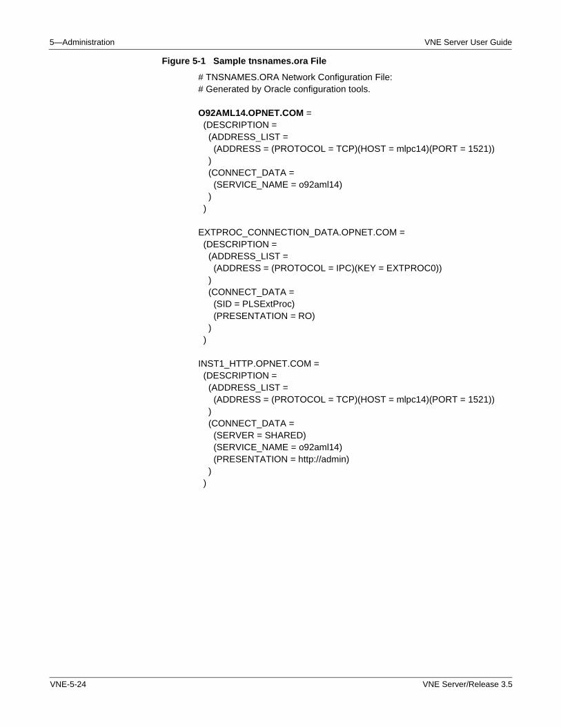
5—Administration VNE Server User Guide
Figure 5-1 Sample tnsnames.ora File
# TNSNAMES.ORA Network Configuration File:# Generated by Oracle configuration tools.
O92AML14.OPNET.COM = (DESCRIPTION = (ADDRESS_LIST = (ADDRESS = (PROTOCOL = TCP)(HOST = mlpc14)(PORT = 1521)) ) (CONNECT_DATA = (SERVICE_NAME = o92aml14) ) )
EXTPROC_CONNECTION_DATA.OPNET.COM = (DESCRIPTION = (ADDRESS_LIST = (ADDRESS = (PROTOCOL = IPC)(KEY = EXTPROC0)) ) (CONNECT_DATA = (SID = PLSExtProc) (PRESENTATION = RO) ) )
INST1_HTTP.OPNET.COM = (DESCRIPTION = (ADDRESS_LIST = (ADDRESS = (PROTOCOL = TCP)(HOST = mlpc14)(PORT = 1521)) ) (CONNECT_DATA = (SERVER = SHARED) (SERVICE_NAME = o92aml14) (PRESENTATION = http://admin) ) )
VNE-5-24 VNE Server/Release 3.5
VNE Server User Guide 5—Administration
Account Management
The procedures in this section describe how to setup, verify, and remove the VNE Server tablespace and user account from the Oracle database.
Setting Up VNE Server Database Accounts within Oracle
This procedure is normally performed following VNE Server installation when VNE Server is initially setup to access the Oracle database. If you have removed the VNE Server database tablespace and account from Oracle to recover from a problem, use this procedure to recreate the tablespace and a user account.
Note—The setup_accounts.sql script used in this procedure removes the existing tablespace and account before creating a fresh tablespace and account. All network model data is lost.
Procedure 5-14 Configure the Oracle Database for Use by VNE Server
1 Open a command prompt window and navigate to the VNE Server installation directory by typing
cd <install path>\VNEServer\3.5.A
2 Type sqlplus system/<system password> in the command prompt window.
3 At the sqlplus prompt, type: @setup_accounts.sql
➥ A list of DBIDs and database instance names are displayed. If you only have a database dedicated to VNE Server, one entry will appear. If more than one database is available, contact your database administrator to find out which database name is used with VNE Server.
Note—Note the correct database instance name for use in the next step.
4 The script prompts you for a database name.
Enter the database instance name obtained in step 3 (use lowercase letters).
5 The script prompts for the database User password.
Enter the same Oracle database password that was specified during VNE Server installation.
Note—When running this script after drop_accounts.sql has been run, SQL error messages will be displayed and can be ignored. These messages result from the script removing VNE Server table and user accounts that have already been removed by the drop_accounts.sql script.
This SQL script configures database storage for VNE Server use and sets up the Oracle user account for VNE Server. After this script finishes, the Oracle account for VNE Server uses the user name and password entered during VNE Server installation.
VNE Server/Release 3.5 VNE-5-25
5—Administration VNE Server User Guide
6 Type quit to exit sqlplus.
End of Procedure 5-14
Verifying the Oracle Configuration
This procedure verifies that the VNE Server database account is setup correctly.
Procedure 5-15 Verifying the Oracle Configuration
1 Type sqlplus <user name>/<password> in the command prompt window. Enter the user name and password you entered during VNE Server installation.
If Oracle configuration was successful, an Oracle banner, and a Connected To: message appears. Type quit at the SQL> prompt to exit.
If Oracle configuration failed, error messages appear stating that login has been denied. Should this happen, execute Setting Up VNE Server Database Accounts within Oracle on page VNE-5-25 again, and re-execute this procedure to check the outcome. If configuration problems persist, contact OPNET Technical Support.
2 Type quit to exit sqlplus.
End of Procedure 5-15
Removing VNE Server Database Accounts within Oracle
This procedure removes the VNE Server tablespace and user account from the Oracle database used by VNE Server. Run this procedure if you want to remove VNE Server content from an Oracle database you no long plan to use for VNE Server.
WARNING—This procedure removes VNE Server’s database. All network model data will be lost.
Procedure 5-16 Remove the VNE Server Tablespace and User Account from the Oracle Database
1 Open a command prompt window and navigate to the VNE Server installation directory by typing
cd <install path>\VNEServer\3.5.A
2 Within this window, type sqlplus system/<system password> to enter sqlplus.
3 Type @drop_accounts.sql <database name>.
➥ Progress messages appear in the command prompt window as the VNE Server user account and tablespace is removed from Oracle.
VNE-5-26 VNE Server/Release 3.5
VNE Server User Guide 5—Administration
4 Type quit to exit sqlplus.
End of Procedure 5-16
Monitoring the Database
The Oracle DBA Studio application is used to monitor the database for Oracle8i. For Oracle9i, use the Enterprise Manager Console. With these tools, you can monitor the following items:
• Tablespace utilization within the database
• Active user sessions within the database
Use the following procedures to enter DBA Studio or the Enterprise Manager Console and perform some routine tasks to monitor the database.
• Entering DBA Studio or Enterprise Manager Console and connecting to the database.
• Getting database instance information.
• Checking database tablespace size.
• Extending the database tablespace size.
• Checking the active database sessions.
These procedures are described in detail throughout the remainder of this section.
Note—For Oracle9i users, enter the Enterprise Manager Console to perform the DBA Studio procedures listed below. Once inside the Console, the steps are the same as for DBA Studio.
Procedure 5-17 Enter DBA Studio and Connect to Oracle8i Database
1 Start Oracle DBA Studio by selecting Start > Programs > Oracle > Database Administration > DBA Studio.
➥ The Oracle Enterprise Manager Login panel opens.
2 Choose the Launch DBA Studio Standalone radio button and press OK.
➥ DBA Studio opens.
3 Expand the property tree for the database used with VNE Server.
➥ A Database Connect Information dialog box opens.
VNE Server/Release 3.5 VNE-5-27
5—Administration VNE Server User Guide
4 Enter the user name and password that you use for the VNE Server account and press OK.
➥ The database property tree expands.
End of Procedure 5-17
Procedure 5-18 Enter Enterprise Manager Console and Connect to Oracle9i Database
1 Start Enterprise Manager Console by selecting Start > Programs > Oracle > Enterprise Manager Console.
➥ The Oracle Enterprise Manager Login panel opens.
2 Choose the Launch Standalone radio button and press OK.
➥ Enterprise Manager Console opens.
3 Expand the property tree for the database used with VNE Server.
➥ A Database Connect Information dialog box opens.
4 Enter the user name and password that you use for the VNE Server account.
5 Choose SYSDBA from the Connect As menu and press OK.
➥ The database property tree expands.
End of Procedure 5-18
At this point, you can navigate anywhere in the property tree for this database.
Procedure 5-19 Obtain Oracle8i Database Instance Information
1 Follow Procedure 5-17 to enter Oracle DBA Studio and connect to your database.
➥ DBA Studio is open with an expanded database property tree.
2 Expand the Instance property tree.
VNE-5-28 VNE Server/Release 3.5
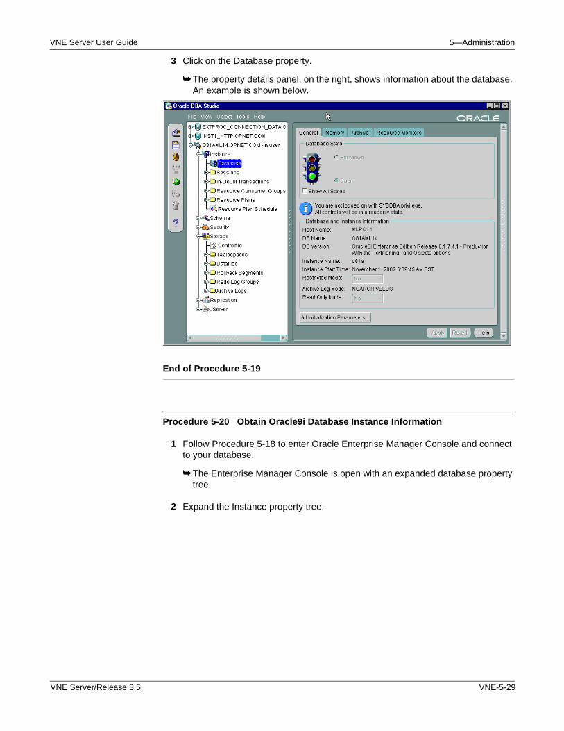
VNE Server User Guide 5—Administration
3 Click on the Database property.
➥ The property details panel, on the right, shows information about the database. An example is shown below.
End of Procedure 5-19
Procedure 5-20 Obtain Oracle9i Database Instance Information
1 Follow Procedure 5-18 to enter Oracle Enterprise Manager Console and connect to your database.
➥ The Enterprise Manager Console is open with an expanded database property tree.
2 Expand the Instance property tree.
VNE Server/Release 3.5 VNE-5-29
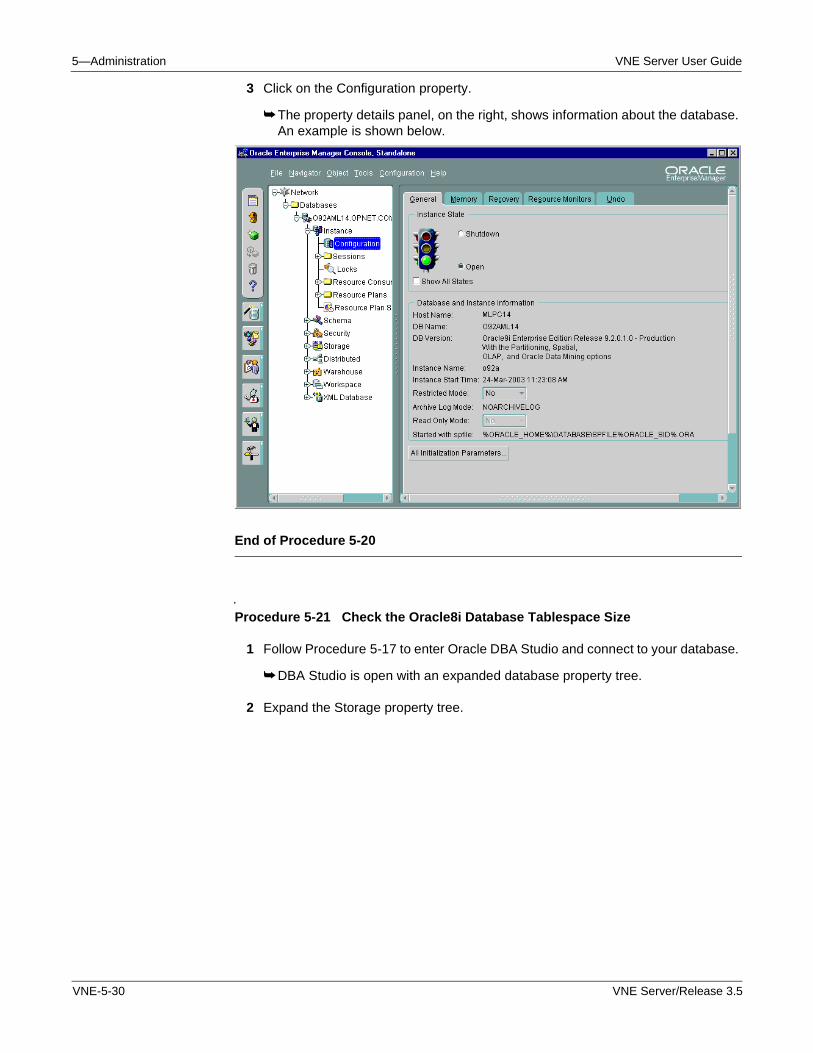
5—Administration VNE Server User Guide
3 Click on the Configuration property.
➥ The property details panel, on the right, shows information about the database. An example is shown below.
End of Procedure 5-20
Procedure 5-21 Check the Oracle8i Database Tablespace Size
1 Follow Procedure 5-17 to enter Oracle DBA Studio and connect to your database.
➥ DBA Studio is open with an expanded database property tree.
2 Expand the Storage property tree.
VNE-5-30 VNE Server/Release 3.5
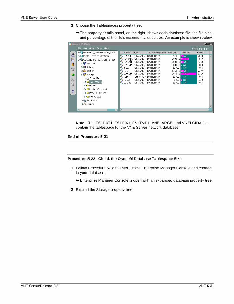
VNE Server User Guide 5—Administration
3 Choose the Tablespaces property tree.
➥ The property details panel, on the right, shows each database file, the file size, and percentage of the file’s maximum allotted size. An example is shown below.
Note—The FS1DAT1, FS1IDX1, FS1TMP1, VNELARGE, and VNELGIDX files contain the tablespace for the VNE Server network database.
End of Procedure 5-21
Procedure 5-22 Check the Oracle9i Database Tablespace Size
1 Follow Procedure 5-18 to enter Oracle Enterprise Manager Console and connect to your database.
➥ Enterprise Manager Console is open with an expanded database property tree.
2 Expand the Storage property tree.
VNE Server/Release 3.5 VNE-5-31
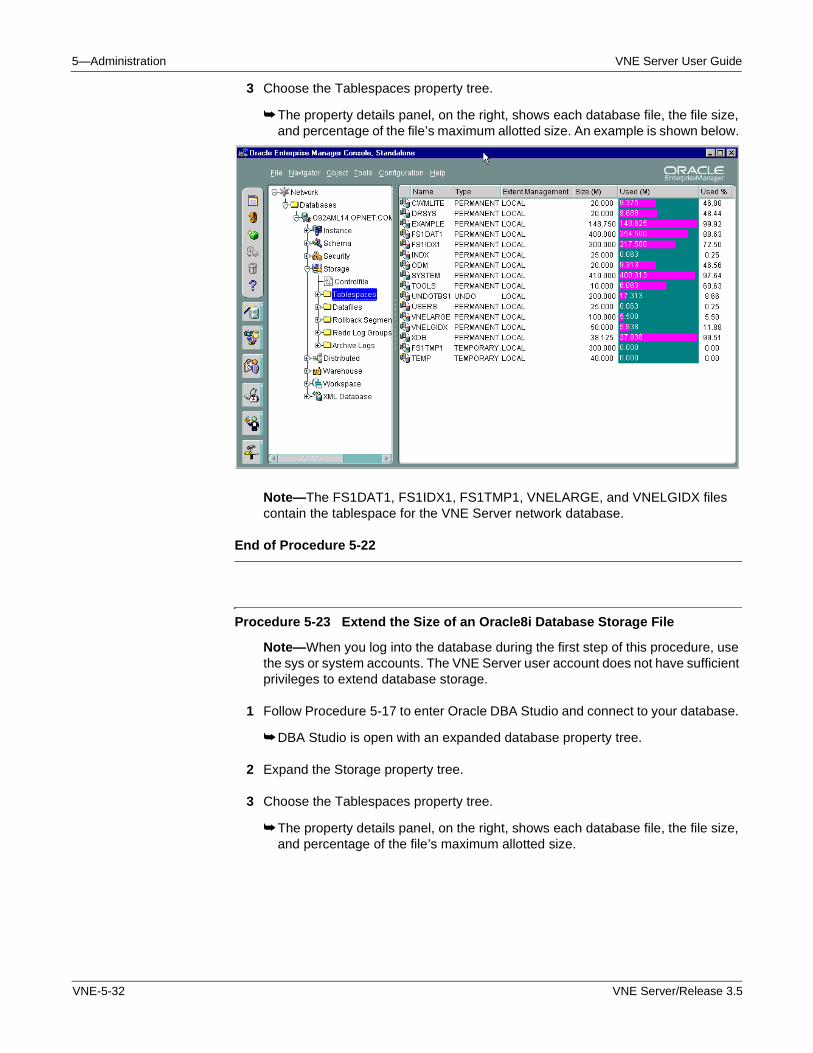
5—Administration VNE Server User Guide
3 Choose the Tablespaces property tree.
➥ The property details panel, on the right, shows each database file, the file size, and percentage of the file’s maximum allotted size. An example is shown below.
Note—The FS1DAT1, FS1IDX1, FS1TMP1, VNELARGE, and VNELGIDX files contain the tablespace for the VNE Server network database.
End of Procedure 5-22
Procedure 5-23 Extend the Size of an Oracle8i Database Storage File
Note—When you log into the database during the first step of this procedure, use the sys or system accounts. The VNE Server user account does not have sufficient privileges to extend database storage.
1 Follow Procedure 5-17 to enter Oracle DBA Studio and connect to your database.
➥ DBA Studio is open with an expanded database property tree.
2 Expand the Storage property tree.
3 Choose the Tablespaces property tree.
➥ The property details panel, on the right, shows each database file, the file size, and percentage of the file’s maximum allotted size.
VNE-5-32 VNE Server/Release 3.5
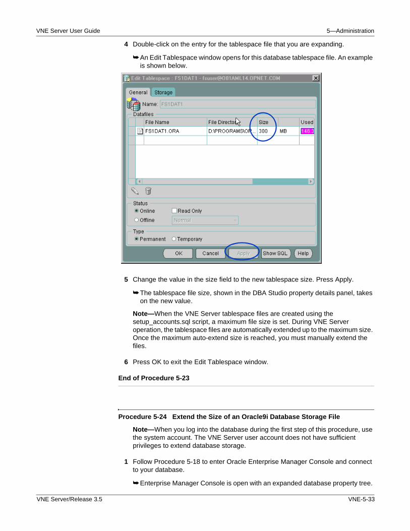
VNE Server User Guide 5—Administration
4 Double-click on the entry for the tablespace file that you are expanding.
➥ An Edit Tablespace window opens for this database tablespace file. An example is shown below.
5 Change the value in the size field to the new tablespace size. Press Apply.
➥ The tablespace file size, shown in the DBA Studio property details panel, takes on the new value.
Note—When the VNE Server tablespace files are created using the setup_accounts.sql script, a maximum file size is set. During VNE Server operation, the tablespace files are automatically extended up to the maximum size. Once the maximum auto-extend size is reached, you must manually extend the files.
6 Press OK to exit the Edit Tablespace window.
End of Procedure 5-23
Procedure 5-24 Extend the Size of an Oracle9i Database Storage File
Note—When you log into the database during the first step of this procedure, use the system account. The VNE Server user account does not have sufficient privileges to extend database storage.
1 Follow Procedure 5-18 to enter Oracle Enterprise Manager Console and connect to your database.
➥ Enterprise Manager Console is open with an expanded database property tree.
VNE Server/Release 3.5 VNE-5-33
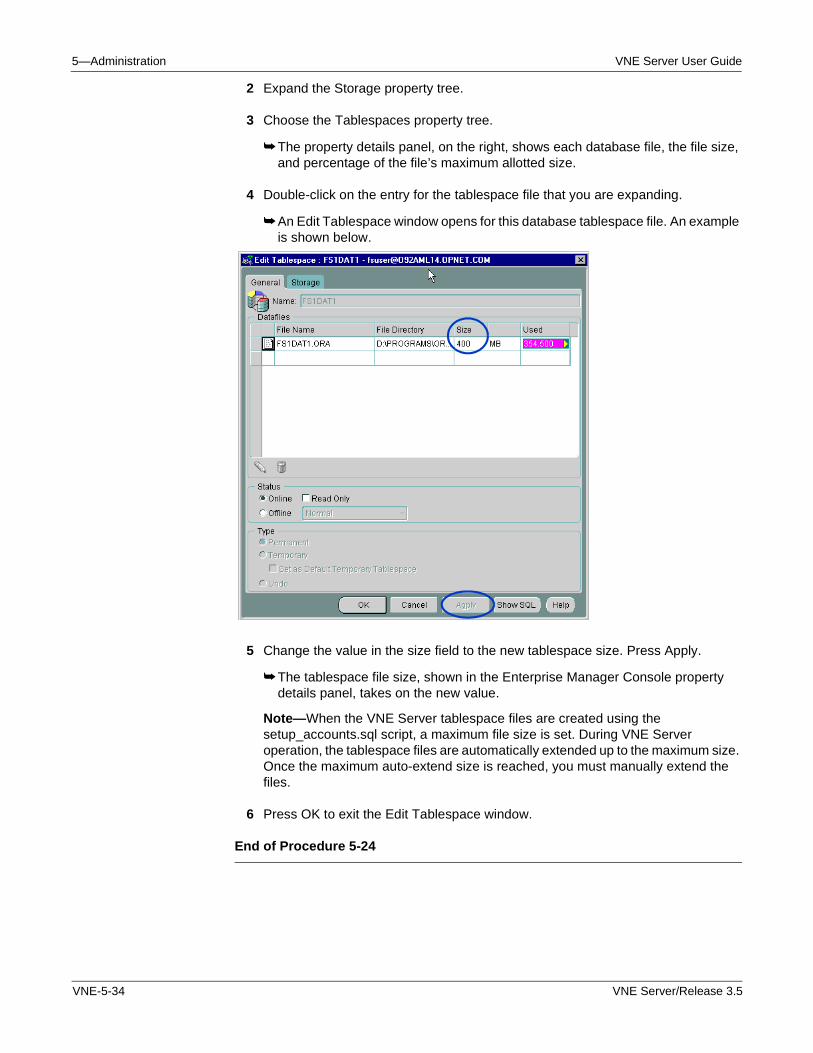
5—Administration VNE Server User Guide
2 Expand the Storage property tree.
3 Choose the Tablespaces property tree.
➥ The property details panel, on the right, shows each database file, the file size, and percentage of the file’s maximum allotted size.
4 Double-click on the entry for the tablespace file that you are expanding.
➥ An Edit Tablespace window opens for this database tablespace file. An example is shown below.
5 Change the value in the size field to the new tablespace size. Press Apply.
➥ The tablespace file size, shown in the Enterprise Manager Console property details panel, takes on the new value.
Note—When the VNE Server tablespace files are created using the setup_accounts.sql script, a maximum file size is set. During VNE Server operation, the tablespace files are automatically extended up to the maximum size. Once the maximum auto-extend size is reached, you must manually extend the files.
6 Press OK to exit the Edit Tablespace window.
End of Procedure 5-24
VNE-5-34 VNE Server/Release 3.5
VNE Server User Guide 5—Administration
Procedure 5-25 Check the Active Sessions Against the Database
1 Follow Procedure 5-17 to enter Oracle DBA Studio (Oracle8i) or Procedure 5-18 to enter Enterprise Manager Console (Oracle9i) and connect to your database.
➥ DBA Studio or Enterprise Manager Console opens with an expanded database property tree.
2 Expand the Instance property tree.
3 Choose the Sessions property tree.
➥ The property details panel, on the right, displays details about each database session.
End of Procedure 5-25
Backup and Recovery
Most database applications require periodic backup of the database. Due to the nature of the VNE Server product, database backup is not essential. Using a restored database with VNE Server presents two problems.
• If the database was backed up under an older version of VNE Server, data schema changes may have occurred in the current release such that the recovered database is no longer usable.
• The other problem relates to the age of the backup. If the network configuration has changed significantly since the backup was created, VNE Server will take as much time to update the database to the current state of the network as it would take to populate a fresh database. For most networks, VNE Server can completely populate a network database in a matter of hours.
If you decide to keep backups of your network database, follow Oracle’s procedures for performing backup and recovery operations. VNE Server provides scripts that can be used to backup and restore the user environment and tablespaces that constitute the VNE database. Refer to the following procedures.
Note—The following procedures can be used to backup and restore a local VNE database but not a remote one.
Procedure 5-26 Backup the VNE database using the vnes_db_export.bat Script
1 Stop VNE services and exit VNE Server.
VNE Server/Release 3.5 VNE-5-35
5—Administration VNE Server User Guide
2 Open a command prompt window and navigate to the VNE Server installation directory by typing:
cd <install path>\VNEServer\3.5.A
3 Type: vnes_db_export.bat <DB username>/<DB password>
Where DB username and DB password are used by VNE Server to access the database.
➥ Numerous progress messages appear that contain backup details.
➥ When complete, the following files are created:
• vnes_db.dmp - backup file of the VNE database
• vnes_db_export.log - log file of the export session
End of Procedure 5-26
Procedure 5-27 Restore the VNE database using the vnes_db_import.bat Script
WARNING—The database information saved in vnes_db.dmp should only be restored for the same VNE Server release that was used to create the backup database.
1 If VNE Server is operating, stop services and exit.
2 Open a command prompt window and navigate to the VNE Server installation directory by typing:
cd <install path>\VNEServer\3.5.A
3 Run the setup_accounts.sql script per Procedure 5-14, to recreate the VNE database.
WARNING—This step will remove all data that is currently in the VNE database.
4 Copy the vnes_db.dmp file that contains the backed up database to the VNE Server installation directory. If you have renamed the file to something more descriptive (i.e. something with a timestamp), rename it to vnes_db.dmp.
5 Type
vnes_db_import.bat <source DB username> <dest DB username> <dest DB password>
Where the source DB username is for the database account from which the backup file originated; and dest DB username and dest DB password are for the account to which the database is restored.
➥ Numerous progress messages appear that contain restore details.
➥ An “Import terminated successfully...” message appears when done.
End of Procedure 5-27
VNE-5-36 VNE Server/Release 3.5
VNE Server User Guide 5—Administration
Network Management System Administration
Some of the VNE Server adapters connect to third-party network management systems to retrieve data. This section describes configuration work required on these network management systems to provide VNE Server access to the system’s network data.
Configuring HP OpenView
When VNE Server and HP OpenView are located on separate hosts, HP OpenView must be configured to grant VNE Server access.
Procedure 5-28 Configure HP OpenView to Grant Access to VNE Server
1 If you are using UNIX, go to the /etc/opt/OV/share/conf directory on the HP OpenView host. If you are using Windows, go to the <drive>:\OpenView\conf\ directory on the host.
➥ Within this directory, there will be three authorization files: ovw.auth, ovwdb.auth, and ovspmd.auth. These authorization files determine which users and what machines will be able to log into the HP OpenView host.
2 Open each authorization file in a text editor. Each authorization file is divided into two sections: a header section that explains how to use and configure the file, and a section where the remote client machines and users are specified.
3 In the section where the client machines and users are specified, add any client machine name or user name using the following formats:
• For a particular client machine with a particular user logged on:
<machine name> <space> <user name>
• For any user on a particular client machine:
<machine name> <space> +
• For any client machine with a particular user:
+ <space> <user name>
• For any user on any client machine:
+ <space> +
For example, if your user name is Administrator and the client machine name is vnesPC, add the following line:
vnesPC Administrator
to each authorization file.
Note—Minus signs (-) can be used in place of plus signs (+) to deny a particular client machine or user access to the HP OpenView host machine.
VNE Server/Release 3.5 VNE-5-37
5—Administration VNE Server User Guide
4 Save the changes made to each authorization file, and then close the file.
Note—If you edited the .auth files while HP OpenView NNM was running, you MUST restart NNM for the changes to take place.
End of Procedure 5-28
Configuring CiscoWorks
For VNE Server to retrieve configuration files from CiscoWorks, the CiscoWorks host machine must be running a remote shell (rsh/rcp) service. Both Windows and UNIX host machines require configuration in order to accept rcp requests from VNE Server.
CiscoWorks on a Windows Host
When CiscoWorks is located on a Windows host, the CMF rsh/rcp service must be running. Find the Services tool in the Windows Control Panel, and open the Services window to display services. If CMF rsh/rcp service is present but stopped, start it. If the service is not present, install it by running <CiscoWorks install dir>\RemoteNetsysNT\rcmf.exe. After installation is complete, start the service from the Control Panel Services window.
Procedure 5-29 Permit VNE Server Access when CMF rsh/rcp service is Installed on CiscoWorks Host
1 Open a command window. Use cd to set the working directory to the bin directory that holds crmrsh.exe. This directory should be at: C:\Program Files\CSCOpx\bin.
2 Type crmrsh addrhost <hostname> <user name>
where <hostname> is the IP address or hostname of the VNE Server host, and <user name> is the account in which VNE Server runs.
Note—When entering the hostname, use a lowercase, Fully Qualified Domain Name for the VNE Server host.
3 Type net stop crmrsh
4 Type net start crmrsh
5 Test the access changes by doing the following:
5.1 On the VNE Server host, open a command window.
5.2 Type rsh <hostname> -l <user name> dir
VNE-5-38 VNE Server/Release 3.5
VNE Server User Guide 5—Administration
where <hostname> is the IP address or hostname of the CiscoWorks host, and <user name> is the name of the account in which VNE Server runs on its host.
➥ If the test is successful, you will see the contents of a directory on the CiscoWorks host displayed in the command window.
End of Procedure 5-29
After completing these changes, VNE Server can access CiscoWorks on a Windows host machine via rcp to retrieve data.
CiscoWorks on a UNIX Host
Procedure 5-30 Permit VNE Server Access when CiscoWorks is on UNIX
1 Add the name of the VNE Server host to the /etc/hosts.equiv file on the CiscoWorks host.
2 Add an account to the CiscoWorks host that has the same name as the user account from which VNE Server is run on the VNE Server host.
3 Add the name of the VNE Server host machine and user account to the .rhosts file in the user account just created on the CiscoWorks host. The .rhosts file is located in the login directory of the user account and has the following format:
hostname <space> username
For example, if the user name of the account from which VNE Server is run is Administrator, and the VNE Server host name is vnesPC, add the following line:
vnesPC Administrator
to the .rhosts file.
End of Procedure 5-30
After completing these changes, VNE Server can access CiscoWorks on a UNIX host machine via rcp to retrieve data.
Collecting CiscoWorks Server Information
The VNE Server adapters that connect to CiscoWorks databases require connection information about the database. The following procedure describes how to collect this information from CiscoWorks.
If you have access to the CiscoWorks server, the easiest way to get database information is to look in the following files.
• For the RME DB: <CiscoWorks install dir>\databases\rme\orig\odbc.tmp1
• For the ANI DB: <CiscoWorks install dir>\databases\ani\orig\odbc.tmp1
VNE Server/Release 3.5 VNE-5-39
5—Administration VNE Server User Guide
If you cannot find these files, use the following procedure to get this information through the CiscoWorks web interface.
Procedure 5-31 Collecting CiscoWorks Server Information
1 Open a web browser and go to the URL for CiscoWorks. An example is: http://CWpc.acme.com:1741 (include the database port number in the URL).
2 Login as an administrative user, press return.
3 Press the Server Configuration button in the lower left browser panel.
➥ A list of Server Configuration properties is displayed.
4 Press Diagnostics > Collect Server Info.
➥ The right browser panel displays a Collect Server Information window.
5 Press the Create button in the Collect Server Information window,
➥ Within a few minutes a report link appears in the Collect Server Information window.
6 Press the report link and choose the ODBC Configuration link.
➥ A web page is opened that contains CiscoWorks ODBC connection information.
7 Write down the UID, DatabaseName, Commlinks ServerPort, and PWD (password) values for use in configuring the CiscoWorks adapters.
End of Procedure 5-31
Collecting a CiscoWorks Inventory File
A device inventory file from CiscoWorks can be used to create the VNE Server device info file. The following procedure describes how to get this file from CiscoWorks.
Procedure 5-32 Collecting a CiscoWorks Inventory File
1 Open a web browser and go to the URL for CiscoWorks. An example is: http://CWpc.acme.com:1741 (include the database port number in the URL).
2 Login as an administrative user, press return.
3 Press the Resource Manager Essentials button in the lower left browser panel.
➥ A list of Resource Manager Essentials properties is displayed.
4 Press Administration > Inventory > Export to File.
➥ An Export to File window appears in the right browser panel.
VNE-5-40 VNE Server/Release 3.5
VNE Server User Guide 5—Administration
5 Enter a file name to use for the inventory file in the Output File window. Do not include a path in the name.
6 Choose an Output File Format and Output File Version. Any choice will work.
7 Press the Next button.
➥ A Data Export Results window appears that shows the location of the inventory file that has just been created.
8 Press the OK button.
9 Copy the file to a directory that VNE Server can read.
End of Procedure 5-32
Configuring Concord eHealth
VNE Server supports three ways to access Concord eHealth utilization data:
• live—VNE Server directly accesses data from Concord
• local files—Concord places data files on VNE Server host
• remote files—Concord places data files on a remote host
To support live access, Concord data groups must be setup for VNE Server to reference during data retrieval. Use the Concord eHealth/Network facility Reports > Edit Groups to define these groups for your Concord installation.
To support file access (either local or remote), Concord must be configured to save configuration and utilization data to a location accessible to VNE Server. Schedule the data export to occur with the same frequency as you run the Concord eHealth Network Utilization Import adapter.
Refer to Concord eHealth documentation for more information about traffic group setup, data file creation, and scheduling the export of utilization data.
Configuring MRTG
VNE Server can retrieve and use MRTG utilization data when it is stored as either “flat” log files or as RRD files. VNE Server can be configured to collect utilization data from multiple MRTG servers.
The MRTG Interface Utilization Import adapter provides compatibility with Windows FTP servers. On a Windows FTP server, the FTP file path is relative to the FTP server's root directory. In this release, the user specifies the FTP root directory on the FTP server so that VNE Server can resolve the MS-DOS path to the FTP file path. This attribute is configured in MRTG Interface Utilization Import > mrtgServerList > Regular MRTG Server > ftp > ftpRootDir or
VNE Server/Release 3.5 VNE-5-41
5—Administration VNE Server User Guide
MRTG Interface Utilization Import > mrtgServerList > RRD Integrated MRTG Server > ftp > ftpRootDir. For additional information on how to configure the MRTG Interface Utilization adapter to work with a Windows IIS FTP Server, please see FAQ 1486 on the OPNET Support Center website: http://www.opnet.com/support.
In previous releases of VNE Server, the log directory for the MRTG Interface Utilization Import adapter was specified in adapter resources (MRTG Interface Utilization Import > mrtgServerList > Regular MRTG Server > logDir and MRTG Interface Utilization Import > mrtgServerList > RRD Integrated MRTG Server > logDir). This adapter automatically finds the appropriate directory from the MRTG configuration files.
Note—Notice that logDir is no longer a configurable attribute in adapter resources for this adapter.
Configuring InfoVista
The InfoVista username that VNE Server uses to access the InfoVista server must have write privileges on the InfoVista server. Refer to the InfoVista product documentation for more information about server configuration.
VNE-5-42 VNE Server/Release 3.5
VNE Server User Guide App A—Troubleshooting
App A Troubleshooting
Introduction
This chapter describes troubleshooting steps you can take to investigate and solve problems that can occur during VNE Server operation. With any problem you encounter, verify that the product setup is correct. If the problem involves a data collection failure, verify access to the problem device, as well. If the suggested troubleshooting steps do not solve the problem, collect all the requested information before you contact OPNET Technical Support.
If you cannot solve the problem using the documentation, gather the following information before you contact OPNET Technical Support.
1) Fill out a Technical Support Request, and document the problem scenario. Refer to Filing an OPNET Technical Support Case on page VNE-A-34 for more instructions.
2) If the VNE Server Event Viewer shows events relevant to the problem, use File > Save to save these events to a log file.
3) Send any event log files you create, the adapterStats file, and the services log files to Technical Support.
Note—The adapterStats file is located in <install dir>\log\adapterStats directory. The services log files are located in the <install dir>\log directory.
VNE Server/Release 3.5 VNE-A-1
App A—Troubleshooting VNE Server User Guide
Tips for Using VNE Server
The following sections describe useful practices.
• Do not stop VNE Server services during database export. This causes the export to abort. No useful data will be available.
VNE Server exports the database when the Export Service runs and when a user imports from VNE Server into OPNET analysis software. The latter is referred to as a “client-initiated” export from VNE Server.
— To check if an scheduled export is in progress, open the VNE Server Console. If the Export Service is running, a database export is ongoing.
— To check if a client-initiated export is in progress, use the Live Event Log Viewer as described below. (Note: The VNE Server Console does not indicate when a client-initiated database export is in progress.)
a) Open the Live Event Log Viewer and set to View > All Events. This includes debug events.
b) Look for recent and continuing events indicating that an export is ongoing:
Source= Export Service_VNE_EXPORT_SERVICE_2_4_a_0 Description= Export Service exported another chunk
c) When the export has completed, the following debug message appears, and it is safe to stop VNE services:
Source= VNE_EXPORT_SERVICE_2_4_a_0 Description= Export Service ends export Data= Completed processing the export request
d) Set the Live Event Log Viewer to the previous view by selecting View > Filter Events. Press the Apply button.
• Do not stop VNE Server services during scheduled export of reports. This terminates the export of the current report, and no further reports are exported. Reports that have already been exported are available, but the set of exported reports will not be complete. To check if a report export is running, open the VNE Server Console. If the Report Export Service is running, a report export is ongoing.
• Do not enable the tracking of database changes until after initial data import is complete and a baseline model is created.
• Run Database Aging Service to remove stale data from the database.
• Run Maintenance Service to remove collected data, logs and other temporary files.
• Run Change Records Maintenance Service whenever you enable tracking of database changes.
VNE-A-2 VNE Server/Release 3.5
VNE Server User Guide App A—Troubleshooting
• Add Interface Utilization Rollup Service to your schedule, if you are importing utilization data into VNE Server.
• Add Demand Traffic Processing Service and Demand Traffic Rollup Server to your schedule, if you are importing demand flow data into VNE Server.
Data Collection
Some data collection restrictions are listed here.
• The Remote File Collection adapter cannot retrieve files from a directory path that contains embedded spaces.
• On some Windows 2000 systems, the CiscoWorks Config File Collection adapter will not terminate after data is collected. This blocks further VNE Server operation. To continue VNE Server operation, press return, and exit the open rsh window. You can work around this problem by replacing the rsh.exe program in the Winnt\system32 directory with an rsh.exe program from a Windows NT system.
• If you are using Window PuTTY or Windows default rcp to perform remote operations (such as plink, pscp, or psftp) for the CiscoWorks Config File Collection or HP OpenView Performance Agent import adapter, you must set the “Log on as” property of the OPNET VNES Adapter Server to the Windows user running VNE Server. Failure to set this property correctly may result in error messages or timeouts. (FAQ 1529).
Export of Detailed Reports
Many reports provide links to detailed reports when viewed in the Report Manager. In previous versions of VNE Server, Report Export Service exported only the top level reports. When a report is exported to HTML, the detailed reports are also exported. A hyperlink is added to preserve the relation between the reports. Links to detailed reports display in blue in your web browser.
Note—Due to the increased number of reports being exported, you may use significantly more disk space when you run the Report Export Service. By default, the maximum number of exported report directories is 20. To conserve disk space you may wish to change this to a smaller number by selecting Management Console Adapter Resources > Report Export Service > Export to directory > Max number of time-stamped archive subdirectories.
VNE Server/Release 3.5 VNE-A-3
App A—Troubleshooting VNE Server User Guide
Network Browser
• Keep the Network Browser closed during initial data import. The Network Browser, when open, is informed of network changes as data collection occurs. The Network Browser, when open, is informed of changes to the VNE Server database. Leaving the Network Browser closed during initial import of your network will enhance performance.
• Opening network browser against a large network when VNE Server services are stopped may cause an out of memory exception.
Data Collection
Some data collection restrictions are listed here.
• The Remote File Collection adapter cannot retrieve files from a directory path that contains embedded spaces.
• On some Windows 2000 systems, the CiscoWorks Config File Collection adapter will not terminate after data is collected. This blocks further VNE Server operation. To continue VNE Server operation, press return, and exit the open rsh window. You can work around this problem by replacing the rsh.exe program in the Winnt\system32 directory with an rsh.exe program from a Windows NT system.
• If you are using Window PuTTY or Windows default rcp to perform remote operations (such as plink, pscp, or psftp) for the CiscoWorks Config File Collection or HP OpenView Performance Agent import adapter, you must set the “Log on as” property of the OPNET VNES Adapter Server to the Windows user running VNE Server. Failure to set this property correctly may result in error messages or timeouts. (FAQ 1529).
Data Import
The name of an aggregate interface on a Catalyst switch is generated at the time of the aggregate interface creation, rather than explicitly specified, and is not included in the device configuration file. The Device Config File Import adapter must therefore infer a name based on the member ports, as defined in the configuration. This inferred name may not match the CatOS-generated name contained in the interface MIB, and merge issues may result.
Hostname Changes
If a device hostname or system name is changed by a network administrator, it may affect VNE Server. This section describes how to manage these changes.
Device Duplication By default the VNE Server adapter priority used for the sysName model attribute is set to an equal value for all adapters. If you have changed the sysName adapter priority settings, and a hostname is changed, you may see duplicate representations of the same physical device in the network model.
VNE-A-4 VNE Server/Release 3.5
VNE Server User Guide App A—Troubleshooting
When hostnames are changed in your network, VNE Server may produce the same device or portions of the device under both names, especially if you are using third-party network management products as data sources. You can recover from this scenario by using the Network Browser to delete the duplicate devices from your model. In your third-party data sources, remove the obsolete device data and re-import from that source.
As a last resort, you can block import of the device from the adapter that is a source for the device and delete the obsolete device from the database. Use the Network Browser for both operations.
Impact on Device Groups When device names change, any device groups that reference the device by the old name will no longer include the device. The old name will still appear in the device group, but the device no longer shows up in a model when its device group is imported into a Guru client. If the device is a member of any blocked import groups, data import from the blocked source will resume for the device.
Naming Conventions
VNE Server imposes few restrictions on the names given to devices in your network. Device names may contain spaces, slashes, backslashes, and punctuation marks. Some unusual combinations that are not currently supported are listed below.
Hostname and System Name Restrictions
• If the hostname of a device comprises a series of dots (one or more), no splitting is performed on the name to separate it into host.domain. If the hostname is “....foo.com”, the device is imported to VNE as “...”; the domain is ignored.
• Cisco devices with hostnames longer than 29 characters are imported as 2 devices.
• Devices with a hostname ending in a “\” character are imported into the network model with “\” missing from the name.
• Devices with hostnames that contain XML special character elements either fail to be imported or are imported incorrectly. Character strings such as “>” and “<” will be converted to “>” and “<“ respectively. Other XML elements may cause data import problems.
Interface Description Restrictions
Interface descriptions that contain XML special character elements fail to be imported or are imported incorrectly. Character strings such as “>” and “<” will be converted to “>” and “<“ respectively. Other XML elements may cause data import problems.
VNE Server/Release 3.5 VNE-A-5
App A—Troubleshooting VNE Server User Guide
Duplicate IP Addresses
Duplication of IP addresses in network data may interfere with VNE Server’s ability to correctly merge objects and infer connections.There may be a valid reason why IP addresses are duplicated in your network. There may also be instances where duplicate IP addresses are being reported by the device operating system either as intended behavior for a particular configuration or as a result of a software problem.
• The Adapter Merge Warnings (Devices Merged) and Adapter Merge Warnings (Interfaces Merged) reports are provided to help determine if unexpected merging of devices and interfaces is occurring.
• In order to prevent interfaces with duplicate IP addresses from being matched and merged in the VNE Server database, create an IP Address Merge Exclusions text file listing the duplicated IP addresses. Open the Management Console and select the Project Properties tab. Set the “exclude from IP address merge rule” property to point to your created text file.
• For the purposes of link inference, if an interface is administratively down, the interface will not be considered as a link endpoint. However, if there are duplicate IP addresses for interfaces, and these interfaces are not administratively down, connections may not be inferred correctly. Consult the Duplicate IP Address report to determine if this may be problem.
Juniper ERX devices report the same IP address on interfaces that are configured on different virtual routers. For example:
virtual-router FOOinterface FastEthernet 1/0.1
ip address 10.1.1.1 255.255.255.0!virtual-router BARinterface FastEthernet 1/0.2
ip address 10.1.1.1 255.255.255.0!
This has implications for both interface merging and link inference. An IP Address Merge exclusions file can be used to prevent merging based on the duplicate IP address; however link inference will still infer links using this address.
Duplicate MAC Addresses
Some vendor devices report duplicate MAC addresses on interfaces. This may interfere with VNE Server’s ability to correctly merge objects and infer connections.
The Adapter Merge Warnings (Devices Merged) and Adapter Merge Warnings (Interfaces Merged) reports are provided to help determine if unexpected merging of devices and interfaces is occurring.
VNE-A-6 VNE Server/Release 3.5
VNE Server User Guide App A—Troubleshooting
In order to prevent interfaces with duplicate MAC addresses from being matched and merged in the VNE Server database, create a text file that lists the duplicated MAC Addresses. Open the Management Console, and select the Project Properties tab. Set the exclude from MAC address merge rule property to point to your created text file.
When the CAM engine is enabled in Link and Connection Inference, MAC address forwarding tables are used to infer connections between Layer-2 devices. Duplicated MAC Addresses may lead to inference of extra links. Consult the Duplicate MAC Address report to determine if this may be a problem. A workaround is to use the CamPruneDupMacAddrs advanced option in Link and Connection Inference. When this feature is enabled and duplicate MAC addresses are encountered, only one of the interfaces with duplicate MAC address is chosen as a link endpoint. Please see Link and Connection Inference Service on page VNE-3-37 for additional information.
SysName Not Set
VNE Server uses complex rules to match and merge devices in the VNE Server database during import. Some configuration data types have more identifying features than others. If a device does not have “sysname” set, some of the data for that device may not be matched and merged properly. Consult the “SysName Not Set” report to determine if there are any devices in your network that do not have sysname set. Address all issues, then collect and import data for these devices again.
SysName-Prompt Mismatch
VNE Server uses complex rules to match and merge devices in the VNE Server database during import. Some configuration data types have more identifying features than others. When a device has the sysname set to one value and the prompt set to another non matching value, some of the data for that device may not be matched and merged properly. Consult the “SysName-Prompt Mismatch” report to determine if there are any devices in your network for which sysname and prompt do not match. Address all issues, then collect and import data for these devices again.
Report Manager
Report Manager can experience an out of memory exception when attempting to open certain reports for a very large database (in terms of number of nodes and/or number of interfaces).
Report Export Service
Report Export Service can experience an out of memory exception when attempting to export certain reports for a very large database (in terms of number of nodes and/or number of interfaces).
VNE Server/Release 3.5 VNE-A-7
App A—Troubleshooting VNE Server User Guide
Database Access
When VNE Server detects problems with database access, the service framework is automatically shut down, and Emergency level messages are displayed in the Event Viewer. This can happen if the network database is down, unreachable, or in a bad state. The service framework will also shut down if data that violates the underlying table schema is imported into the database. Some examples of this are type mismatches between data and table schema or a field overflow situation. Data problems may arise when receiving invalid or unexpected data from a 3rd party product or directly from a device polled by VNE Server. In either case, services will shut down when the invalid data item is encountered. Contact OPNET Technical Support for assistance when you encounter this situation. To work around this situation, open the VNE Server Management Console. Select the Project Properties panel, and expand VNESFeatures. Set the “stopServicesOnDatabaseFailures” property to false. Apply the change, and restart services.
VNE-A-8 VNE Server/Release 3.5
VNE Server User Guide App A—Troubleshooting
Preparing to Collect Data Using VNE Server
VNE Server is designed to use many of the leading third-party network management products as sources of information about your network. Depending upon operational practice, however, many of these products may retain stale or inaccurate information. For example, when devices undergo a name change, data about the device, under its old name, may be retained. When this data is imported into VNE Server, you may notice obsolete devices in the network model. If you adequately prepare before importing data into VNE Server, you will ensure a smoother integration with your network management environment.
Before adding VNE Server to your Network Management environment, OPNET recommends the following actions:
• Inventory each 3rd party product to be used with VNE Server
— Ensure that data collection intervals support your requirements for a near real-time view of the network by VNE Server. Modify as necessary.
— Identify stale data. Consider refreshing all data in third-party products before the first import into VNE Server.
— Review operational procedures for your network management products. Modify as necessary to ensure that complete and current information about your network is available for use by VNE Server.
• Review device configuration practices
— Configure an identical system prompt for all devices in your network, if you intend to have VNE Server directly collect configuration files from the devices.
— Review the Restrictions and Limitations section on Data Import on page VNE-A-9 for unsupported device naming conventions. Rename devices that have names violating these limitations.
Data Import
The name of an aggregate interface on a Catalyst switch is generated at the time of the aggregate interface creation, rather than explicitly specified, and is not included in the device configuration file. The Device Config File Import adapter must therefore infer a name based on the member ports, as defined in the configuration. This inferred name may not match the CatOS-generated name contained in the interface MIB, and merge issues may result.
Hostname Changes
If a device hostname or system name is changed by a network administrator, it may affect VNE Server. This section describes how to manage these changes.
VNE Server/Release 3.5 VNE-A-9
App A—Troubleshooting VNE Server User Guide
Device Duplication By default the VNE Server adapter priority used for the sysName model attribute is set to an equal value for all adapters. If you have changed the sysName adapter priority settings, and a hostname is changed, you may see duplicate representations of the same physical device in the network model.
When hostnames are changed in your network, VNE Server may produce the same device or portions of the device under both names, especially if you are using third-party network management products as data sources. You can recover from this scenario by using the Network Browser to delete the duplicate devices from your model. In your third-party data sources, remove the obsolete device data and re-import from that source.
As a last resort, you can block import of the device from the adapter that is a source for the device and delete the obsolete device from the database. Use the Network Browser for both operations.
Impact on Device Groups When device names change, any device groups that reference the device by the old name will no longer include the device. The old name will still appear in the device group, but the device no longer shows up in a model when its device group is imported into a Guru client. If the device is a member of any blocked import groups, data import from the blocked source will resume for the device.
Naming Conventions
VNE Server imposes few restrictions on the names given to devices in your network. Device names may contain spaces, slashes, backslashes, and punctuation marks. Some unusual combinations that are not currently supported are listed below.
Hostname and System Name Restrictions
• If the hostname of a device comprises a series of dots (one or more), no splitting is performed on the name to separate it into host.domain. If the hostname is “....foo.com”, the device is imported to VNE as “...”; the domain is ignored.
• Cisco devices with hostnames longer than 29 characters are imported as 2 devices.
• Devices with a hostname ending in a “\” character are imported into the network model with “\” missing from the name.
• Devices with hostnames that contain XML special character elements either fail to be imported or are imported incorrectly. Character strings such as “>” and “<” will be converted to “>” and “<“ respectively. Other XML elements may cause data import problems.
Interface Description Restrictions
VNE-A-10 VNE Server/Release 3.5
VNE Server User Guide App A—Troubleshooting
Interface descriptions that contain XML special character elements fail to be imported or are imported incorrectly. Character strings such as “>” and “<” will be converted to “>” and “<“ respectively. Other XML elements may cause data import problems.
Duplicate IP Addresses
Duplication of IP addresses in network data may interfere with VNE Server’s ability to correctly merge objects and infer connections.There may be a valid reason why IP addresses are duplicated in your network. There may also be instances where duplicate IP addresses are being reported by the device operating system either as intended behavior for a particular configuration or as a result of a software problem.
• The Adapter Merge Warnings (Devices Merged) and Adapter Merge Warnings (Interfaces Merged) reports are provided to help determine if unexpected merging of devices and interfaces is occurring.
• In order to prevent interfaces with duplicate IP addresses from being matched and merged in the VNE Server database, create an IP Address Merge Exclusions text file listing the duplicated IP addresses. Open the Management Console and select the Project Properties tab. Set the “exclude from IP address merge rule” property to point to your created text file.
• For the purposes of link inference, if an interface is administratively down, the interface will not be considered as a link endpoint. However, if there are duplicate IP addresses for interfaces, and these interfaces are not administratively down, connections may not be inferred correctly. Consult the Duplicate IP Address report to determine if this may be problem.
Juniper ERX devices report the same IP address on interfaces that are configured on different virtual routers. For example:
virtual-router FOOinterface FastEthernet 1/0.1
ip address 10.1.1.1 255.255.255.0!virtual-router BARinterface FastEthernet 1/0.2
ip address 10.1.1.1 255.255.255.0!
This has implications for both interface merging and link inference. An IP Address Merge exclusions file can be used to prevent merging based on the duplicate IP address; however link inference will still infer links using this address.
Duplicate MAC Addresses
Some vendor devices report duplicate MAC addresses on interfaces. This may interfere with VNE Server’s ability to correctly merge objects and infer connections.
VNE Server/Release 3.5 VNE-A-11
App A—Troubleshooting VNE Server User Guide
The Adapter Merge Warnings (Devices Merged) and Adapter Merge Warnings (Interfaces Merged) reports are provided to help determine if unexpected merging of devices and interfaces is occurring.
In order to prevent interfaces with duplicate MAC addresses from being matched and merged in the VNE Server database, create a text file that lists the duplicated MAC Addresses. Open the Management Console, and select the Project Properties tab. Set the exclude from MAC address merge rule property to point to your created text file.
When the CAM engine is enabled in Link and Connection Inference, MAC address forwarding tables are used to infer connections between Layer-2 devices. Duplicated MAC Addresses may lead to inference of extra links. Consult the Duplicate MAC Address report to determine if this may be a problem. A workaround is to use the CamPruneDupMacAddrs advanced option in Link and Connection Inference. When this feature is enabled and duplicate MAC addresses are encountered, only one of the interfaces with duplicate MAC address is chosen as a link endpoint. Please see Link and Connection Inference Service on page VNE-3-37 for additional information.
SysName Not Set
VNE Server uses complex rules to match and merge devices in the VNE Server database during import. Some configuration data types have more identifying features than others. If a device does not have “sysname” set, some of the data for that device may not be matched and merged properly. Consult the “SysName Not Set” report to determine if there are any devices in your network that do not have sysname set. Address all issues, then collect and import data for these devices again.
SysName-Prompt Mismatch
VNE Server uses complex rules to match and merge devices in the VNE Server database during import. Some configuration data types have more identifying features than others. When a device has the sysname set to one value and the prompt set to another non matching value, some of the data for that device may not be matched and merged properly. Consult the “SysName-Prompt Mismatch” report to determine if there are any devices in your network for which sysname and prompt do not match. Address all issues, then collect and import data for these devices again.
Report Manager
Report Manager can experience an out of memory exception when attempting to open certain reports for a very large database (in terms of number of nodes and/or number of interfaces).
VNE-A-12 VNE Server/Release 3.5
VNE Server User Guide App A—Troubleshooting
Report Export Service
Report Export Service can experience an out of memory exception when attempting to export certain reports for a very large database (in terms of number of nodes and/or number of interfaces).
Database Access
When VNE Server detects problems with database access, the service framework is automatically shut down, and Emergency level messages are displayed in the Event Viewer. This can happen if the network database is down, unreachable, or in a bad state. The service framework will also shut down if data that violates the underlying table schema is imported into the database. Some examples of this are type mismatches between data and table schema or a field overflow situation. Data problems may arise when receiving invalid or unexpected data from a 3rd party product or directly from a device polled by VNE Server. In either case, services will shut down when the invalid data item is encountered. Contact OPNET Technical Support for assistance when you encounter this situation. To work around this situation, open the VNE Server Management Console. Select the Project Properties panel, and expand VNESFeatures. Set the “stopServicesOnDatabaseFailures” property to false. Apply the change, and restart services.
Licensing
VNE Server has the following restrictions and limitations with respect to product licensing.
• VNE Server requires an OPNET 11.0 license server and a license file in the 11.0 format.
• Standalone licensing is not supported by VNE Server.
• Loanable licenses are not supported by VNE Server.
• Only one local license server may be installed on the VNE Server host.
• The OPNET licensing software deployed with VNE Server does not include the License Manager user interface. Instead, a command line utility, LS_UTIL, is provided.
• VNE Server’s command line licensing utility (LS_UTIL) cannot revoke a license managed by a remote license server.
Common Operations
This section describes how to find information commonly required during troubleshooting.
VNE Server/Release 3.5 VNE-A-13
App A—Troubleshooting VNE Server User Guide
Locating VNE Server Release Information
You must always provide VNE Server product release information when contacting OPNET Technical Support. To locate VNE Server release information, select Help > About VNE Server on the Console menu bar to display a release information panel.
The major release (i.e., 3.5.A), patch level (i.e., PL1), and build number (i.e., 800) appear near the bottom of the About panel. An example of the version information is shown below:
Version: 3.5.A PL1 (Build 800)
Locating Oracle Release Information
If you need to locate Oracle release information, you must run sqlplus, using the following procedure:
Procedure A-1 Locate Oracle Release Information
1 Open a command window.
2 Type sqlplus to enter sqlplus.
3 Enter the username for the VNE Server account at the username prompt.
4 Enter the password for the VNE Server account at the password prompt.
➥ The sqlplus login banner appears, containing Oracle edition and version information as shown below.
Connected to:Oracle8i Enterprise Edition Release 8.1.7.4.1 - ProductionWith the Partitioning optionJServer Release 8.1.7.4.1 - Production
5 Note the information, and type quit to exit sqlplus.
6 Close the command window.
End of Procedure A-1
VNE-A-14 VNE Server/Release 3.5
VNE Server User Guide App A—Troubleshooting
Determining the Oracle Database Used by VNE Server
If you need to identify the database instance name used by VNE Server, do the following:
Procedure A-2 Determine Oracle Database Used by VNE Server
1 Locate the installation directory for Oracle.
Note—The Oracle Database Administrator (DBA) will know Oracle’s location. You can also use the Windows Find utility to locate Oracle. Use “oracle” for a search string.
2 Go to the ..oracle\oradata directory.
This directory contains directories for each Oracle database instance.
3 Look in each directory for the following file: Fs1dat1.ora.
The name of the directory that contains this file is the name of VNE Server’s Oracle database.
4 Note the names of the database instances.
End of Procedure A-2
Determining the Oracle Net Service Names Known to the VNE Server Host
You may need to locate the Oracle Net service names during troubleshooting. The tnsnames.ora file contains these names. The file is located here:
<oracle_install_dir>\<ora81 or ora92>\network\Admin\tnsnames.ora
You can read this file in text editors such as Notepad or Wordpad. The Net service name entries have the following structure:
<net_service_name> = (service_definitions)
The text string before the “=” is the Net service name.
Problem Scenarios
For each problem scenario, verify the correct configuration of VNE Server, verify access to the target network, and perform any indicated troubleshooting steps. If the problem persists, collect the specified information for OPNET Technical Support before initiating a support case.
Installation Problems
The problem scenarios in this section involve problems that can arise during installation and product startup.
VNE Server/Release 3.5 VNE-A-15
App A—Troubleshooting VNE Server User Guide
VNE Server Installation Fails
Scenario: The VNE Server installer fails to run. Alternately, the installer runs to completion but tells you that the installation failed.
Possible Causes: The following failures can occur. For each cause, take corrective action, or collect the specified information.
1) There is not enough free disk space for installation.
If you do not have enough disk space to install VNE Server, the installer displays a message box informing you of this problem. Remove files from the target disk to free enough space so installation can continue. The installer monitors available disk space and automatically continues when you have enough free space.
2) The installer aborts during installation.
Collect installer console information. Perform the following steps.
a) Press and hold the CTRL key during installer initialization to open an installer console window. A status box with a progress bar displays during initialization. At the end of initialization the console opens. After the console window opens, release the CTRL key.
b) Change the console window properties to provide a 2000 line screen buffer.
Press OK, and choose Modify shortcut which started this window. This change ensures that you have enough window buffer space to capture all the installer console activity.
c) Close the installer console. The installer terminates.
d) Run the installer again.
Once again, press and hold the CTRL key during installer initialization to open an installer console window. After the console window opens, release the CTRL key.
e) Continue the installation to the point at which the failure occurred. Cut and paste the installation console text into a text file. Forward this file to OPNET Technical Support.
3) The installation completes with a failed status.
The most likely causes of this failure are that the installer failed to copy files, failed post-installation editing, or failed to execute a command. Forward the installation logs to OPNET Technical Support. The files are:
— <install_dir>\InstallLogs\installer_debug.log
— <install_dir>\InstallLogs\OPNET_VNE_Server_InstallLog.log
VNE-A-16 VNE Server/Release 3.5
VNE Server User Guide App A—Troubleshooting
Collect Debug Information: Forward installation logs, installer console information, or screenshots to OPNET Technical Support.
Cannot Run the Oracle Installer
Scenario: The Oracle8i installer terminates immediately after it is started.
Recovery: To work around this problem, perform the following steps:
1) Create a temporary directory on your Oracle host.
2) Copy the contents of the Oracle RDBMS Server CD to the temporary directory created in step 1.
3) Search the directory structure created in step 1 for the existence of the filename symcjit.dll.
4) Rename each copy of the symcjit.dll to symcjit.old.
5) Run setup.exe from the directory you created in step 1, and install Oracle 8.1.x.
Note—For more information about this problem, refer to Oracle Metalink Doc ID: Note:131299.1. The following URL also contains information about this problem: http://www.orafaq.com/msgboard/windows/messages/1040.htm.
Cannot Start VNE Server
Scenario: The VNE Server Console does not appear after starting the product.
Symptoms: You clicked on the VNE Server desktop icon or used the Program Group menu to start VNE Server, but the Console never opens.
Possible Causes: This problem may involve an installation error. This can occur if, during startup, VNE Server cannot resolve a product definition or cannot find a referenced file. This problem can also occur if the product .jar files or XML control files become corrupted.
Recovery: If this is a new installation or upgrade, delete the newly installed VNE Server directory tree, and try the installation again.
If the problem persists, startup VNE Server in a debug window, as follows:
1) Open a command prompt window, and set the working directory to the installation directory: <install dir>\VNEServer\3.5.
VNE Server/Release 3.5 VNE-A-17
App A—Troubleshooting VNE Server User Guide
2) Type vnes.bat /debug ev to start VNE Server (Oracle8i). A window opens and displays startup messages (INFO).
Note—If using an Oracle9i database, type: vnes.bat /Oracle9i /debug ev.
3) Cut and paste the contents of the startup window into a file for Technical Support.
The messages displayed in this window may contain error information or exceptions that help identify the cause of the startup problem.
Collect Debug Information: Forward the startup window message file, from step 3, and the installation logs to OPNET Technical Support. The installation logs are
• <install dir>\InstallLogs\installer_debug.log
• <install dir>\InstallLogs\OPNET_VNE_Server_InstallLog.log
Cannot Start VNE Server Services
Scenario: The VNE Server services fail to start.
Symptoms: The Console and Control Panel open, but the service framework fails to start when you start VNE Server services. Alternately, the progress box that appears when services are started may display messages about a process failing to start.
Recovery: Try to start VNE Server services as follows:
1) Exit VNE Server.
2) Restart VNE Server. After the Control Panel appears, start services.
3) If services still do not startup, exit VNE Server.
4) Use the Windows Task Manager to terminate any rmid.exe and javaw.exe processes running on the system.
5) Start VNE Server, and try starting services again. If the problem still occurs, delete the log directory from the VNE Server installation directory, terminate any rmid.exe and javaw.exe processes and try again.
Collect Debug Information: If you cannot successfully start VNE Server services using the methods described above, collect debug information for Technical Support as follows:
1) Start VNE Server. After the Control Panel opens, select Configuration > Open Management Console from the menu bar.
VNE-A-18 VNE Server/Release 3.5
VNE Server User Guide App A—Troubleshooting
2) Select the Management Console Project Properties panel.
3) Expand the debug property. Set the state property to true.
4) Press OK to exit the Management Console.
5) Exit VNE Server.
6) Open a command prompt window, and set the working directory to the installation directory at <install dir>\VNEServer\3.5.
7) Type vnes.bat /debug ev to start VNE Server (Oracle8i). A window opens and displays startup messages (INFO).
Note—If using an Oracle9i database, type: vnes.bat /Oracle9i /debug ev.
8) After the Control Panel opens, start VNE Server services.
Note—Services may still fail to startup.
VNE Server System Failure on Windows XP SP2
Background: Windows XP Service Pack 2 (SP2) introduced a new security feature in TCP/IP that imposes a limit of 10 on the number of incomplete TCP connection attempts per second. During collection by certain adapters, particularly Device Config File Collection, VNE Server may need to open outbound connections to multiple devices simultaneously. If multiple connections are slow to establish, VNE Server may experience a system failure.
Scenario: VNE Server services shutdown unexpectedly during a collection.
Possible Causes: This scenario can occur when there are incorrect passwords configured for a large number of devices in the Device Info File. It can also occur when multiple devices are not acknowledging connection attempts during a collection adapter run.
Recovery: Before troubleshooting further, examine the Windows Event Viewer to see if the system has reached this limit. Look for TCP/IP warnings that say, “TCP/IP has reached the security limit imposed on the number of concurrent TCP connect attempts” [Event 4226]. If this is the problem, use any of the following workarounds:
• Restart your system in Safe mode. Edit the limit in tcpip.sys.
VNE Server/Release 3.5 VNE-A-19
App A—Troubleshooting VNE Server User Guide
• Download and install the patching program for removing or changing the limit imposed on connection attempts. Install this program at your own risk. Backup tcpip.sys in a safe location before running the installer. The patching program is available here: http://www.speedguide.net/files/xp_sp2/EvlD4226Patch211a-en.zip. You can reach the author of this patch at http://www.lvllord.de.
• Limit the concurrent connections in the Device Config File Collection adapter to 1. This will result in longer collection times.
VNE Server Cannot Connect to the Database
Scenario: When you start VNE Server, the Console does not appear. A message box appears and informs you that a database connection cannot be established.
Possible Causes: Either the database is not reachable, or the database name entered during installation of VNE Server does not match an entry in the Oracle tnsnames.ora file.
Recovery: •
• Verify that the Oracle database you are using (local or remote host) is in service. If it is not in service, restore the database to service.
• If the database is on another host and is in service, verify that it is reachable.
Type tnsping <database name>. If you get a TNS: no listener response, the database is not reachable. Correct the network problem.
• The most likely cause of this problem is that the database name entered during VNE Server installation does not match any known Oracle Net Services name.
— Edit the <install dir>\lib\xml\dtd\props_Oracle8i.dtd file (props_Oracle9i.dtd for Oracle9i installations). Search for a line in the file that contains “fs.db.name”. The quoted database name in this line should match an entry in the Oracle tnsnames.ora file. Refer to Oracle Net Services on page VNE-5-23 for information about the tnsnames.ora file format.
— Open the <oracle install dir>\ora81\network\ADMIN\tnsnames.ora file for Oracle8i.
VNE-A-20 VNE Server/Release 3.5
VNE Server User Guide App A—Troubleshooting
Or open the <oracle install dir>\ora92\network\ADMIN\tnsnames.ora file for Oracle9i.
— You may see that the name used in the props_Oraclexx.dtd file matches an entry in tnsnames.ora, but is misspelled. Correct the error in the dtd file. Save and exit the file.
• Another common cause of this problem is that a fully-qualified hostname (i.e., vnesdb.opnet.com) was entered for the database name during VNE Server installation, when the entry in tnsnames.ora is actually vnesdb. Correct errors of this nature in the dtd file.
Try, once again, to start VNE Server. If the problem persists, contact OPNET Technical Support.
Collect Debug Information: Take a screenshot of the error dialog box, or write down the error message. Forward the information and the following two files to OPNET Technical Support:
• Oracle8i: <install dir>\lib\xml\dtd\props_Oracle8i.dtd
Oracle9i: <install dir>\lib\xml\dtd\props_Oracle9i.dtd.
• Oracle8i: <oracle install dir>\ora81\network\ADMIN\tnsnames.ora
Oracle9i: <oracle install dir>\ora92\network\ADMIN\tnsnames.ora
VNE Server/Release 3.5 VNE-A-21
App A—Troubleshooting VNE Server User Guide
Configuration Problems
The problem scenarios in this section involve problems that can arise during product configuration.
Cannot Communicate with the Target Network
Scenario: Config file collection and SNMP-based MIB data collection fails for all the network devices immediately after data collection starts. The Event Viewer shows numerous events of Error severity that describe device access problems.
Possible Causes: There may be an error in your VNE Server setup, or the target devices may be inaccessible.
Verify Setup: Verify configuration of the host platform, VNE Server, and the target network, by checking the following items:
1) Use the route print command in a Command Prompt window to verify that the host PC has a route to the gateway of the target network. If no route exists, create a route.
2) Check the VNE Server device access information for the target network to ensure that device IP addresses, login information, and community strings are correct. Correct any problems.
3) Verify that devices in the target network have telnet enabled. Enable telnet on devices that have telnet disabled.
Verify Access: Verify access to the target network.
1) Ping the gateway that provides access into the target network. Ping interfaces on several devices in the target network. Run tracert to inaccessible addresses.
2) If you can ping device interfaces in the target network, verify that you can use telnet to access several different devices.
If access to the target network is the problem, fix any configuration or network problems.
Collect Debug Information: If the problem persists after you have verified VNE Server setup and access to the target network, collect the standard SPR Report information, as detailed in Filing an OPNET Technical Support Case on page VNE-A-34, and contact OPNET Technical Support.
VNE-A-22 VNE Server/Release 3.5
VNE Server User Guide App A—Troubleshooting
No Network Data is Written to the Oracle Database
Scenario: The VNE Server Event Viewer indicates that the adapters are running and that data is being collected, but the Report Manager reports contain no data. Additionally, the Event Viewer may contain events of Critical severity that describe database problems.
Verify Setup: Verify that Oracle services are running, the database is accessible, and the VNE Server accounts are setup correctly.
1) Verify that the Oracle TNSListener and OracleService services are running, using the path specific to your operating system. Start these services, if they are not running:
Windows NT: Start > Settings > Control Panel > Services
Windows 2000: Start > Settings > Control Panel > Administrative Tools > Services
2) Use Oracle DBA Studio (Oracle8i) to verify that the database used by VNE Server is available and is setup correctly. Verify that the global database name (GDN) entered during Oracle installation is visible in DBA Studio. If the database is not visible, create the database.
For Oracle9i, use the Enterprise Manager Console for this step.
3) If the VNE Server database is visible, expand its display. Make sure that the view is By Schema (using View > By Schema). Expand Schema and verify that the VNE Server account entry exists. (This is the Oracle account name entered during VNE Server installation). If it does not exist, rerun setup_accounts.sql within sqlplus. See Setting Up VNE Server Database Accounts within Oracle on page VNE-5-25, for instructions.
Collect Debug Information: If the problem persists after you correct any of the database problems above, collect the following files before calling OPNET Technical Support:
• In the directory ...\Oracle\admin\<database instance name>\create, collect the createdb.log and dbSilentCreate.log files.
• In the directory ...\Oracle\admin\<database instance name>\pfile, collect init.ora.
Send these files with the standard SPR Report information to OPNET Technical Support.
The Oracle Database Does Not Restart Correctly After PC startup
Scenario: The VNE Server Console indicates that adapters are running and that data is being collected, but the Report Manager reports contain no data. The Event Viewer may contain events of Critical severity that describe database problems.
VNE Server/Release 3.5 VNE-A-23
App A—Troubleshooting VNE Server User Guide
Verify Setup: Verify correct Oracle setup per No Network Data is Written to the Oracle Database on page VNE-A-23.
If Oracle services are running and the database has been configured correctly for VNE Server, use the Windows Task Manager to view Oracle memory usage. A database dedicated to VNE Server will use more than 70 MB of memory, if Oracle starts up properly. If the displayed memory usage is much lower than normal, Oracle has probably not started up properly.
Recovery: If Oracle memory usage is much less than 70 MB, perform the following steps to restart.
For Oracle8i:
1) In a command window, type: svrmgrl.
2) At the svrmgrl prompt (svrmgrl>), type: connect internal.
3) Type shutdown.
4) Type startup.
5) Type quit.
For Oracle9i:
1) In a command window, type: sqlplus “/ as sysdba”.
2) Type startup open <database name> parallel.
3) Type quit.
When Oracle is running, check its memory usage again. If Oracle memory usage is much higher now (tens of MB), Oracle is ready for operation with VNE Server.
Collect Debug Information: If the problem persists after you correct the database problems above, collect the following files:
• In the directory ...\Oracle\admin\<database instance name>\create, collect the createdb.log and dbSilentCreate.log files.
• In the directory ...\Oracle\admin\<database instance name>\pfile, collect init.ora.
Send these files with the standard SPR Report information to OPNET Technical Support.
VNE-A-24 VNE Server/Release 3.5
VNE Server User Guide App A—Troubleshooting
Adapters Do Not Run as Intended
Scenario: The VNE Server Console does not show one or more adapters running. The Report Manager does not show the data collected by one or more adapters.
Verify Setup: Use the Management Console Adapter Schedule panel to verify that the problem adapters have been enabled. Enable any adapters that are disabled, if these adapters are supposed to be running.
Collect Debug Information: If the problem adapters are enabled but the problem persists, collect the standard SPR Report information, and contact OPNET Technical Support.
Configuration Files are Not Collected or Imported
Scenario: The config file import adapters (Device Config File Import or CiscoWorks Config File Import) cannot locate any configuration files. The output file directories for the config file collection adapters are empty.
Note—The Device Config File Collection adapter collects files that are imported by the following adapters: Device Config File Import, Device ifIndex Import, Device FR Map Import, Device Version Import, Device IP Route Import, Device CDP Import, Device ARP Table Import, Device Interface Import, Device Module Import, Device CAM Table Import, and Device VLAN Database Import.
Note—The CiscoWorks Config File Collection adapter collects files that are imported by the CiscoWorks Config File Import adapter.
Verify Setup: Check the following items:
1) Examine the Event Viewer for events of Error severity that describe device access problems.
2) Use the Management Console Adapter Schedule panel to verify that the proper config file collection adapter is enabled. View the Console Adapter Statistics to determine whether the adapter has ever run. Enable the adapter, if it is currently disabled.
3) Use the Management Console Adapter Resources panel to verify that the output file directory of the proper config file collection adapter matches the input file directory of the associated config file import adapter. Correct any directory mismatches.
4) Check the output file directory of the config file collection adapter to ensure there are configuration files.
VNE Server/Release 3.5 VNE-A-25
App A—Troubleshooting VNE Server User Guide
Verify Access: Verify there is access to target devices and that login information is correct. For Cisco routers, verify that Privileged Exec mode is accessible.
Collect Debug Information: If you cannot solve the problem using the steps listed above, collect the standard SPR Report information, and contact OPNET Technical Support.
Configuration Files are Not Collected for a Specific Device
Scenario: Configuration files are not collected for a device. The Network Browser and Report Manager do not show information for the device.
Verify Setup: View the device access entry in the Device and Platform Info panel of the Management Console. Verify that the device login information is correct. Correct any problems.
Verify Access: Ping the target device to verify access. Telnet to the target device to verify that it is accessible. Verify access to Privileged Exec mode. Correct any problems.
Collect Debug Information: If the problem persists, collect the standard SPR Report information, and contact OPNET Technical Support.
MIB Data is Not Collected for a Specific Device
Scenario: The Report Manager does not show any data obtained from MIBs for a specific device. The Event Viewer shows events of Error severity that describe access problems with the problem device.
Verify Setup: View the device access entry in the Device and Platform Info panel of the Management Console. Verify that the SNMP community string is correct. Correct any problems.
Verify Access: If you have access to other products that can do SNMP queries (HP OpenView, AdventNet, etc.), collect System group information from the target device to verify both access and the community string.
Verify SNMP: Verify that the device’s SNMP agent is running.
Collect Debug Information: If the problem persists, collect the standard SPR Report information, and contact OPNET Technical Support.
VNE-A-26 VNE Server/Release 3.5
VNE Server User Guide App A—Troubleshooting
Operation Problems
The problem scenarios in this section involve problems that can arise during continuous operation.
Oracle ORA-4031 Shared Pool Memory Allocation Errors
Scenario: The VNE Server Event Viewer displays Critical events informing the user of database problems.
Verify Setup: This problem is common with Oracle 8.1.7.0 installations. VNE Server requires an Oracle 8.1.7.4.1 database for operation. Verify that the 8.1.7.4.1 patch is installed. Install the patch if you are running Oracle 8.1.7.0. The patch fixes shared pool memory problems in Oracle.
Verify proper Oracle setup per No Network Data is Written to the Oracle Database on page VNE-A-23. If Oracle services are running and the database has been configured properly for VNE Server, the OPNETVNESBootstrapService.log. This log file is located at <install dir>\log\ OPNETVNESBootstrapService.log
To view the log file, make a copy of the file and open it using a text editor. Search for “ORA-”, “ORA-4031”, “error”, and “exception”.
Recovery: If ORA-4031 errors are present in the OPNETVNESBootstrapService.log
1) Stop VNE Server data collection by selecting Services > Stop Services from the Control Panel menu bar.
2) Exit VNE Server by selecting File > Exit from the Control Panel menu bar.
3) Shutdown and restart Oracle, using the appropriate path for your operating system and selecting the service OracleServiceO81A:
Windows: Start > Settings > Control Panel > Administrative Tools > Services.
4) After Oracle has restarted, start VNE Server using the OPNET VNE Server selection within the OPNET VNE Server program group.
5) Start VNE Server data collection by selecting Services > Stop Services from the Control Panel menu bar.
6) Monitor operation for an hour or more. No Critical events regarding the database should appear in the Event Viewer.
Collect Debug Information: If the problem persists, collect the standard SPR Report information, and contact OPNET Technical Support.
VNE Server/Release 3.5 VNE-A-27
App A—Troubleshooting VNE Server User Guide
Services Halt and Database Error Events Appear in the Event Viewer
Scenario: The VNE Server Event Viewer shows events of Emergency and Critical severity that describe database problems. The service framework shuts down.
Causes: Any kind of a database access error can cause this problem. If there is no free tablespace for the database, this problem will also occur. This problem may also occur if data written to the database does not match the underlying schema.
Recovery: If the database is out of service, restore it to service. If connectivity to a remote database is lost, restore connectivity. Exit VNE Server, re-enter and restart services to recover.
If the problem is caused by data that violates the underlying database schema, turn off the “auto shutdown” feature as follows:
1) Open the VNE Server Management Console.
2) Open the Project Properties panel.
3) Set the stopServicesOnDatabaseFailures property to false.
4) Press the Apply button to save the changes.
5) Start services and start your data collection schedule.
Collect Debug Information: Forward the services logs and event logs to OPNET Technical Support. If possible, zip the temp dir and forward that to OPNET Technical Support, as well. If you cannot provide this data, for security reasons, save the temp dir in a location accessible to you for joint troubleshooting with OPNET Technical Support.
Removing and Recreating VNE Server User Account and Database from Oracle
Scenario: A serious problem has developed with the network database that can only be corrected by removing and recreating the VNE Server account and database.
WARNING—Never perform this procedure unless advised to do so by OPNET Technical Support. All VNE Server data in the Oracle database is removed by this procedure.
Recovery: To remove the VNE Server user account and database from Oracle, and recreate a fresh account and database, perform the steps in Setting Up VNE Server Database Accounts within Oracle on page VNE-5-25.
VNE-A-28 VNE Server/Release 3.5
VNE Server User Guide App A—Troubleshooting
Collect Debug Information: If the database cannot be removed and recreated, forward any screen output captured during this procedure to OPNET Technical Support.
Unexpected Devices are Present in the Network Database
Scenario: The Report Manager and Network Browser show devices that are not expected to be in the target network.
Verify Setup: Check the following items:
1) Verify that the ASCII Import files reference only devices that are in the target network. Incorrect setup of the ASCII Import adapter can result in extra devices appearing in the network database. Correct any problems.
2) View the device access information in the Device and Platform Info panel of the Management Console. Verify that the device access information only includes devices in the target network. Correct any problems.
3) Make sure adapters that gather information from other data collection systems (such as Concord eHealth) are configured correctly. If the Concord adapter is incorrectly configured to communicate with a Concord system in a different target network, extra devices can be included in the network database. Correct any problems.
Collect Debug Information: If the problem persists, collect the standard SPR Report information, and contact OPNET Technical Support.
Device Asset Information is Not Collected for a Device
Scenario: The Report Manager Asset Inventory report does not show device hardware configuration information for a device. Other MIB data, such as the System Description, is present in reports.
Possible Causes: The device may not support the ENTITY-MIB. VNE Server collects hardware configuration information from this MIB.
Collect Debug Information: If the device supports the ENTITY-MIB, collect the standard SPR Report information, and contact OPNET Technical Support.
Failure to Connect to the CiscoWorks RME Database
Scenario: The CiscoWorks RME Database Import adapter fails to connect to the database. The VNE Server Event Viewer shows connection failure events.
Verify Setup: Use the Management Console Adapter Resources panel to verify that the RME database connection properties for this adapter are correct. Correct any problems found.
VNE Server/Release 3.5 VNE-A-29
App A—Troubleshooting VNE Server User Guide
Recovery: This problem may also occur due to the RME database getting into a state where it no longer accepts connections. Perform the following steps to clear this problem by resetting the RME database.
1) Open a web browser and go to the URL for the CiscoWorks RME database. An example is: http://CWpc.acme.com:1741 (include the database port number in the URL).
2) Login as an administrative user, and press return.
3) Press the Server Configuration button in the lower left browser panel.
4) Select the Administration, Process Management, and Stop Process choices in the Server Configuration panel.
The right browser panel displays a Stop Process dialog box.
5) Select the Process radio button in the stop field of the Stop Process dialog box.
6) Select the EssentialsDbEngine process from the Process Name pull-down menu and press Finish.
A message appears stating that the process is stopped.
7) Press Start Process in the Server Configuration panel.
The right browser panel displays a Start Process dialog box.
8) Select the Process radio button in the start field of the Start Process dialog box.
9) Select the EssentialsDbEngine process from the Process Name drop-down menu and press Finish.
A message appears stating that the process is started.
10) Press Logout to leave the CiscoWorks RME database management environment.
Collect Debug Information: If the problem persists, collect the standard SPR Report information, and contact OPNET Technical Support.
Failure to Connect to the CiscoWorks ANI Database
Scenario: The CiscoWorks ANI Database Import adapter fails to connect to the database. The VNE Server Event Viewer shows connection failure events.
Verify Setup: Use the Management Console Adapter Resources panel to verify that the ANI database connection properties for this adapter are correct. Correct any problems found.
VNE-A-30 VNE Server/Release 3.5
VNE Server User Guide App A—Troubleshooting
Recovery: This problem may also occur due to the ANI database getting into a state where it no longer accepts connections. If this is the case, perform the following steps to clear this problem by resetting the ANI database.
1) Open a web browser and go to the URL for the CiscoWorks ANI database. An example is: http://CWpc.acme.com:1741 (include the database port number in the URL).
2) Login as an administrative user, and press return.
3) Press the Server Configuration button in the lower left browser panel.
4) Select the Administration, Process Management, and Stop Process choices in the Server Configuration panel.
The right browser panel displays a Stop Process dialog box.
5) Select the Process radio button in the stop field of the Stop Process dialog box.
6) Select the ANIDbEngine process from the Process Name pull-down menu, and press Finish.
A message appears stating that the process is stopped.
7) Press Start Process in the Server Configuration panel.
The right browser panel displays a Start Process dialog box.
8) Select the Process radio button in the start field of the Start Process dialog box.
9) Select the ANIDbEngine process from the Process Name pull-down menu and press Finish.
A message appears stating that the process is started.
10) Press Logout to leave the CiscoWorks ANI database management environment.
Collect Debug Information: If the problem persists, collect the standard SPR Report information and contact OPNET Technical Support.
Cannot Import a VNE Server Network Model into the OPNET analysis software
Scenario: Import of VNE Server network model fails when creating a new OPNET analysis software project.
VNE Server/Release 3.5 VNE-A-31
App A—Troubleshooting VNE Server User Guide
Verify Setup: Check the following items:
1) In the OPNET analysis software control panel, select Edit > Preferences to open the Preferences window. Search for the string vne to find the preferences related to VNE Server.
2) Verify that the vne_import_ior_file preference points to the vneserver.ior file. Correct any problems.
a) If VNE Server resides on the same system as OPNET analysis software, this preference must point to the vneserver.ior file in the VNE Server temp directory. This temp directory defaults to C:\op_admin\tmp\vne, but you can change the directory during VNE Server installation.
b) If the two products reside on different systems, verify that this preference points to the ior file based upon your setup scenario.
If you have mapped a network drive so the OPNET analysis software host can directly access the ior file on the VNE Server host, verify that the path is correct. Verify that you can still view the file from the OPNET analysis software host.
If you have copied the ior file to a directory on the OPNET analysis software host, verify that this preference points to the correct path.
3) Verify that the vneserver.ior file remains valid. If VNE Server data collection is stopped, the ior file is removed from the temp directory. Make sure that VNE Server is operating and that this file is present in the temp directory.
If the two products reside on different systems, the ior file can become stale, if VNE Server data collection is stopped and restarted. If this happens, copy the current ior file from the VNE Server host to the VNE Server temp directory on the OPNET analysis software host.
4) Verify that the vne_import_postproc_function preference is set to Vne_Import_Postproc_Default.
5) Verify that the vne_import_postproc_library preference is set to vne_import_postproc.
Verify Access: If VNE Server and OPNET analysis software reside on different systems, verify access by pinging the VNE Server system from the OPNET analysis software system.
Try again: VNE Server (in release 1.1) only supports one model import request at a time. Once an import session is in progress, new import requests will fail. Try again to import a model from VNE Server. VNE Server 1.2 and up support multiple, simultaneous import sessions.
Collect Debug Information: If the problem persists, collect the OPNET analysis software error logs and the standard SPR Report information. Contact OPNET Technical Support.
VNE-A-32 VNE Server/Release 3.5
VNE Server User Guide App A—Troubleshooting
Licensing Problems
The problem scenarios in this section involve problems that can arise with respect to product licensing.
Cannot Obtain a License When Starting VNE Server
Scenario: Services fail to start in the VNE Server Control Panel. An Emergency level event appears in the Event Viewer about a failure to obtain a license.
Recovery: If this problem occurs, perform the following steps to recover.
1) Verify that the License Server is in service and accessible if located on another host.
2) Verify that a license is available for VNE Server.
3) Exit the VNE Server Console. Verify that the op_monitor process is not running. Kill the process, if it is running.
4) Check the VNE Server installation directory for an opmonlock directory. If the directory exists, delete it.
Work through these steps to correct any problems found. After completing them, you should be able to open the VNE Server Console, start service, and obtain a license.
Collect Debug Information: If the recovery steps do not correct your licensing problems, collect the following file, and contact OPNET Technical Support: <install dir>\VNEServer\3.5.A\log\VNE_Event_Viewer.log.
Scenario VNE Server services fail to start, when VNE Server is running a local license server and is rebooted.
Recovery Exit VNE Server and revoke the license through License Manager. For more information on how to revoke a license, see License Operations on page AG-3-12 of the Licensing chapter in the OPNET Administrator Guide.
Services Shut Down Due to License Problems
Scenario: VNE Server has been operating for an extended period of time (hours, days, weeks) when services stop, and an Emergency level event appears in the Event Viewer about a failure to keep a license.
Recovery: If this problem occurs, exit the VNE Server Control Panel. Re-enter the Control Panel, and start services. Services should start up. If they do not, execute the recovery steps in Cannot Obtain a License When Starting VNE Server on page VNE-A-33.
VNE Server/Release 3.5 VNE-A-33
App A—Troubleshooting VNE Server User Guide
Collect Debug Information: If the recovery steps do not correct your licensing problems, collect the following file, and contact OPNET Technical Support: <install dir>\VNEServer\3.5.A\log\VNE_Event_Viewer.log.
Filing an OPNET Technical Support Case
To file a Technical Support case, proceed as follows:
1) Use a web browser to connect to the OPNET Technical Support web site:
http://www.opnet.com/support/home.html
2) Locate the Enter/Update a Tech Support Case section on the web page.
3) Click on the New Case link.
A Tech Support Request Form appears.
4) Fill in all the fields in the form, and press Submit TS Request.
Coordinate with OPNET Technical Support to transfer any data captured during troubleshooting.
VNE-A-34 VNE Server/Release 3.5
VNE Server User Guide App B—Device Configuration Commands
App B Device Configuration Commands
The device configuration commands supported by VNE Server for each vendor are listed in the following sections:
• Cisco PIX Firewall Commands
• Nortel Networks Commands
• Nortel Networks Passport 8000 Commands
• Nortel Networks Passport 7480, 15000, 20000 Commands
• Extreme Commands
• Foundry Commands
• Check Point Nokia IPSO Commands
• Juniper ERX JUNOSe Commands
Note—Cisco IOS, Cisco Catalyst, Cisco PIX Firewall, and Juniper JUNOS command support is detailed on the OPNET Support Website at http://www.opnet.com/support/home1.html. Click on Supported Vendor Protocols and Commands.
VNE Server/Release 3.5 VNES-B-1
App B—Device Configuration Commands VNE Server User Guide
Cisco PIX Firewall Commands
Last updated for release: 3.0 PL1.
• access-group
• access-list
• alias
• domain-name
• established
• filter
• floodguard
• fragment
• global
• hostname
• interface hardware_id [hardware_speed [shutdown]]
• interface hardware_id vlan_id logical [shutdown]
• interface hardware_id vlan_id physical [shutdown]
• ip address
• ip local pool
• ip verify reverse-path
• logging
• mtu
• name / names
• nameif
• nat
• nat [(local_interface)] id local_ip [mask [dns] [outside | [norandomseq] [max_conns [emb_limit]]]]
• "nat [(local_interface)] id access-list acl_name [dns]
• [outside | [norandomseq] [max_conns [emb_limit]]]"
• nat [(local_interface)] 0 access-list acl_name [outside]
• ntp
VNES-B-2 VNE Server/Release 3.5
VNE Server User Guide App B—Device Configuration Commands
• object-group
— object-group icmp-type:
— description
— icmp-object
— group-object
• object-group network:
— description
— network-object host
— network-object
— group-object
• object-group protocol:
— description
— protocol-object
— group-object
• object-group service:
— tcp | udp | tcp-udp
— description
— port-object range
— port-object eq
— group-object
• prefix-list
• rip
• route
• route-map
— match:
interface
metric
ip address
— route-type:
local
internal
external type-1
external type-2
nssa-external type-1
VNE Server/Release 3.5 VNES-B-3
App B—Device Configuration Commands VNE Server User Guide
nssa-external type-2
— ip next-hop
— ip route-source
— set:
metric
metric-type internal
metric-type external
metric-type type-1
metric-type type-2
ip next-hop
• router ospf
— area
— area authentication
— area default-cost
— area nssa:
no-redistribution
default-information-originate:
metric
metric-type 1/2
— area area_id range:
advertise
not-advertise
— area stub
— area stub no-summary
— area virtual-link:
authentication
hello-interval
retransmit-interval
transmit-delay
dead-interval
authentication-key
message-digest-key
— default-information originate:
always
metric
VNES-B-4 VNE Server/Release 3.5
VNE Server User Guide App B—Device Configuration Commands
metric-type 1
metric-type 2
route-map
— distance:
inter-area
intra-area
external
— network
— redistribute:
static
connected
metric
metric-type
route-map
tag
subnets
— router-id
— summary-address:
no-advertise
tag
— timers:
spf
lsa-group-pacing
— routing interface
ospf authentication
ospf authentication-key
ospf cost
ospf database-filter all out
ospf dead-interval
ospf hello-interval
ospf message-digest-key
ospf mtu-ignore
ospf priority
ospf retransmit-interval
ospf transmit-delay
VNE Server/Release 3.5 VNES-B-5
App B—Device Configuration Commands VNE Server User Guide
• service
• snmp-server
• static
• static [(local_ifc,global_ifc)] {global_ip | interface} {local_ip [netmask mask] | access-list acl_name} [dns] [norandomseq] [max_conns [emb_limit]]
• static [(local_ifc,global_ifc)] {tcp | udp} {global_ip | interface} global_port {local_ip local_port [netmask mask] | access-list acl_name} [dns] [norandomseq] [max_conns [emb_limit]]
• sysopt
— connection:
permit-pptp
permit-l2tp
permit-ipsec
tcpmss
— ipsec pl-compatible
— nodnsalias inbound
— nodnsalias outbound
— noproxyarp
— radius ignore-secret
— uauth allow-http-cache
• terminal
• timeout
VNES-B-6 VNE Server/Release 3.5
VNE Server User Guide App B—Device Configuration Commands
Nortel Networks Commands
Last updated for release: 3.0 PL1.
Nortel Network commands include the following:
• Nortel Global Commands
• Nortel Interface Commands
• Nortel RIP Commands
• Nortel BGP/EGP
Nortel Global Commands
• box
• stack
• back
• system-name <name>
• ip
• static-router address <dest addr> mask <dest mask> next-hop-address <next hop>
Nortel Interface Commands
• <interface type> module <module number> slot <slot number> connector <connector number>
• <interface type> slot <slot number> connector <connector number>
• <interface type> slot <slot number> module <module number> connector <connector number>
• circuit-name <interface name>
• ipx address <address>
• ip address <addr> mask <mask>
• mtu <size>
• mtu-mismatch-detect <state>
• type [broadcast | nbma | pointtopoint | ietf | pmp | passive]
• serial [ethernet | hssi | token-ring module <number> slot <number> connector <number>]
• slot <number> connector <number>
VNE Server/Release 3.5 VNES-B-7
App B—Device Configuration Commands VNE Server User Guide
Nortel RIP Commands
• rip
• external-clock-speed <speed>
• frame-relay
• pvc dlci <dlci>
• rip-diameter <max_hops>
• state [enabled | disabled]
• version [rip1 | rip2 | aggr]
• authentication-type [none | simple-password]
• authentication [<number> | <value>]
• supply [enabled | disabled]
• mode [poisoned | actual | split]
• triggered-updates [enabled | disabled]
• ttl <hops>
• listen [enabled | disabled]
• default-supply [enabled | disabled | generated]
• default-listen [enabled | disabled]
• broadcast-timer <seconds>
• timeout-timer <seconds>
• holddown-timer <seconds>
• frsvc [enabled | disabled]
• accept <policy_name>
• announce <policy_name>
• action [ignore | announce | accept | advertise | block]
• preference <number>
• precedence <number>
• match
• modify
• network [addr_mask_and_flag | addr_mask_and_flag]
VNES-B-8 VNE Server/Release 3.5
VNE Server User Guide App B—Device Configuration Commands
• rip-gateway [<ip address> | <ip address>]
• rip-interface
• mask <ip address>
• external-source [any | direct | static | rip | ospf | egp | bgp]
• ospf-type [any | type1 | type2 | external | internal]
• protocol-source [any | direct | static | rip | ospf | egp | bgp]
Nortel OSPF Commands
• ospf
• ospf router-id <router id>
• area area-id <area id>
• ospf area <area>
• metric <metric>
• ospf-router-id ip_address_list
• ospf-tag as_number_list
• outbound-interface ip_address_list
• advertise [<network ID> | <network ID>]
• router-id <ip_address>
• slot-mask [<number> | <value> | <value>]
• as-boundary-router [true | false]
• ase-metric-support <state>
• as-default-tag [default | automatic | proprietary]
• holddown <value>
• lsa-refresh-max <value>
• lsa-refresh-delay <seconds>
• log-mask <mask>
• area <area-id>
• area <ip_address>
• priority <priority>
• transit-delay <delay>
VNE Server/Release 3.5 VNES-B-9
App B—Device Configuration Commands VNE Server User Guide
• retransmission-interval <interval>
• hello-interval <interval>
• dead-interval <interval>
• poll-interval <interval>
• neighbor <ip_address>
• summary network
• summary network <ip_address> mask <ip_mask>
• area-type stub
• area-type nssa
• stub-metric <cost>
• import-summaries false
• nssa-default-ase-path [type1 | type2]
• nssa-default-originate <state>
• nssa-default-propagate <state>
• nssa-translate-to-5 <state>
• nssa-range <network ID>
• ase-tag <value>
• ase-tag number_list
• virtual-link <ip_address>
• authentication-key <value> [retransmit-interval <number>]
• retransmit-interval <interval>
• ase-type [any | default | type1 | type2]
• auto-tag [enabled | disabled | proprietary]
• nssa-propagate <param>
Nortel BGP/EGP
• bgp-as [<number> | <number>]
• bgp-next-hop ip_address_list
• bgp-peer ip_address_list
• egp-as as_number_list
VNES-B-10 VNE Server/Release 3.5
VNE Server User Guide App B—Device Configuration Commands
• egp-gateway ip_address_list
• egp-peer ip_address_list
• inbound-interface ip_address_list
• local-as <local-as>
• intra-as-routing <state>
• redistribute-protocols [bgp | all]
• igp-interaction [none | ospf | rip]
• igp-interaction [<value> | ospf | rip | <value>]
• inject-time <value>
• redundant-connection <state>
• max-redundant-routes <number>
• multi-hop <state>
• subnet-aggregation <state>
• black-hole-punching [disabled | drop | reject]
• med-comparison <state>
• confederation-id <id number>
• confederation-peers <as_numbers>
• peer <network ID> as <number>
• local-pref-calculation <state>
• damping-template name <value>
• cutoff-threshold <number>
• reuse-threshold <number>
• reachable-decay <number>
• unreachable-decay <number>
• max-hold-down <number>
• memory-limit <number>
• as-weight-class <value>
• bgp4-preference <number>
• route-damping <state>
VNE Server/Release 3.5 VNES-B-11
App B—Device Configuration Commands VNE Server User Guide
• route-damping-template <value>
• as-path-pattern [<value> | <value>]
• origin [any | igp | egp | incomplete | none]
• aggregator-as <list of as numbers>
• aggregator-router <list of ip addresses>
• as <list of as numbers>
• community [no-export | no-advertise | no-export-subconfed]
• community [<value> | <value>]
• network <list of ip addresses>
• originating-as <list of as numbers>
• peer <list of addresses>
• as-path-prepend
• local-pref-override <state>
• local-preference <number>
• med-method [none | specified | originating]
• med <number>
• community-method [as-is | remove | append | replace]
• inject <list of ip addresses>
• inbound-as <list of as numbers>
• inbound-peer <list of ip addresses>
• next-hop <list of ip addresses>
• outbound-as <list of as numbers>
• outbound-peer <list of ip addresses>
• as-path [<value> | <number> | <value> | <number>]
• atomic-aggregate [default | force | ignore]
• local-pref-override <state>
• peer local <local_address> remote <remote_address> as <as_number>
• retry <interval>
• min-version [bgp3 | bgp4]
VNES-B-12 VNE Server/Release 3.5
VNE Server User Guide App B—Device Configuration Commands
• max_version [bgp3 | bgp4]
• keepalive <seconds>
• advertise-time <seconds>
• min-originate-time <seconds>
• max-update-size <bytes>
• next-hop-self <state>
• route-echo <state>
• detect-as-loop <state>
• tcp-authentication <state>
• tcp-md5-key <key>
• tcp-md5-key-storage [clear-text | encrypted]
• advertise <ip_address_list>
• traffic-filter filter-name <filter>
VNE Server/Release 3.5 VNES-B-13
App B—Device Configuration Commands VNE Server User Guide
Nortel Networks Passport 8000 Commands
Last updated for release: 3.0 PL1.
• cli prompt <name>
• box type : <node type>
• sys set location <location string>
• ethernet <ifc num> perform-tagging <enable|disable>
• ethernet <ifc num> qos-level <level>
• ethernet <ifc num> name <name>
• ethernet <ifc num> state <enable|disable>
• ethernet <ifc num> speed <value>
• ethernet <ifc num> duplex <half|full>
• ethernet <ifc num> auto-negotiate <enable|disable>
• ethernet <ifc num> lock <true|false>
• ethernet <ifc num> linktrap <enable|disable>
• ethernet <ifc num> ip dhcp-relay <enable|disable>
• ethernet <ifc num> stg <number> stp <enable|disable>
• ethernet <ifc num> stg <number> faststart <enable|disable>
• ethernet <ifc num> stg <number> change-detection <enable|disable>
• ethernet <ifc num> stg <number> pathcost <cost>
• ethernet <ifc num> stg <number> priority <priority>
• ethernet <ifc num> ip ospf metric <metric>
• ethernet <ifc num> ip ospf advertise-when-down <enable|disable>
• ethernet <ifc num> ip ospf area <ipaddr>
• ethernet <ifc num> ip ospf <enable|disable>
• ethernet <ifc num> ip ospf interface_type
• ethernet <ifc num> ip ospf dead-interval <seconds>
• ethernet <ifc num> ip ospf hello-interval <seconds>
• ethernet <ifc num> ip ospf priority <priority>
• ethernet <ifc num> ip rip advertise-when-down <enable|disable>
VNES-B-14 VNE Server/Release 3.5
VNE Server User Guide App B—Device Configuration Commands
• ethernet <ifc num> ip rip auto-aggr <enable|disable>
• ethernet <ifc num> ip rip default-listen <enable|disable>
• ethernet <ifc num> ip rip default-supply <enable|disable>
• ethernet <ifc num> ip rip cost <cost>
• ethernet <ifc num> ip rip <enable|disable>
• ethernet <ifc num> ip rip listen <enable|disable>
• ethernet <ifc num> ip rip in-policy <policy name>
• ethernet <ifc num> ip rip out-policy <policy name>
• ethernet <ifc num> ip rip poison <enable|disable>
• ethernet <ifc num> ip rip supply <enable|disable>
• ethernet <ifc num> ip rip trigger <enable|disable>
• mlt <mid> create
• mlt <mid> name <name>
• mlt <mid> perform-tagging <enable|disable>
• mlt <mid> add ports <ports>
• mlt <mid> add vlan <vid>
• vlan <vid> create byport <sid> [name <name>] [color <color>]
• vlan <vid> create byport <sid>
• vlan <vid> ports remove <ports> member portmember
• vlan <vid> ports add <ports> member portmember
• vlan <vid> ip create <ip address/mask> mac_offset <value>
• vlan <vid> add-mlt <mid>
• vlan ip ospf metric <metric>
• vlan <ifc num> ip ospf advertise-when-down <enable|disable>
• vlan <ifc num> ip ospf area <ipaddr>
• vlan <ifc num> ip ospf <enable|disable>
• vlan <ifc num> ip ospf dead-interval <seconds>
• vlan <ifc num> ip ospf hello-interval <seconds>
• vlan <ifc num> ip ospf priority <priority>
VNE Server/Release 3.5 VNES-B-15
App B—Device Configuration Commands VNE Server User Guide
• vlan <ifc num> ip ospf poll-interval <seconds>
• vlan <ifc num> ip rip advertise-when-down <enable|disable>
• vlan <ifc num> ip rip auto-aggr <enable|disable>
• vlan <ifc num> ip rip default-listen <enable|disable>
• vlan <ifc num> ip rip default-supply <enable|disable>
• vlan <ifc num> ip rip cost <cost>
• vlan <ifc num> ip rip <enable|disable>
• vlan <ifc num> ip rip listen <enable|disable>
• vlan <ifc num> ip rip in-policy <policy name>
• vlan <ifc num> ip rip out-policy <policy name>
• vlan <ifc num> vlan <ifc num> ip rip poison <enable|disable>
• vlan <ifc num> ip rip supply <enable|disable>
• vlan <ifc num> ip rip trigger <enable|disable>
• stg <value> create <ports>
• stg <value> add ports <ports>
• stg <value> forward-delay <timeval>
• stg <value> hello-interval <timeval>
• stg <value> max-age <timeval>
• stg <value> priority <priority>
• stg <value> group-stp <enable|disable>
• stg <value> trap-stp <enable|disable>
• ip static-route create <ip address/mask> next-hop <value> [cost <value>] [preference <value>]
• ip ospf admin-state <enable|disable>
• ip ospf <enable|disable>
• ip ospf router-id <value>
• ip ospf as-boundary-router <enable|disable>
• ip ospf auto-vlink <enable|disable>
• ip ospf default-metric [ethernet <value>] [fast-ethernet <value>] [gig-ethernet <value>]
VNES-B-16 VNE Server/Release 3.5
VNE Server User Guide App B—Device Configuration Commands
• ip ospf holddown <seconds>
• ip ospf trap <enable|disable>
• ip ospf area <area> create
• ip ospf area <area> stub <true|false>
• ip ospf area <area> import-summaries <true|false>
• ip ospf area <area> nssa <true|false>
• ip ospf area <area> stub-metric <value>
• ip ospf area <area> range <ip address/mask> create advertise-mode <mode> lsa-type <type>
• ip ospf area <area> range <ip address/mask> advertise-mode <mode>
• ip ospf area <area> range <ip address/mask> advertise-metric <metric>
• ip ospf interface <ip address> area <area>
• ip ospf interface <ip address> admin-status <enable|disable>
• ip ospf interface <ip address> interface_type <broadcast|nbma|passive>
• ip ospf interface <ip address> create <broadcast|nbma|passive>
• ip ospf interface <ip address> dead-interval <seconds>
• ip ospf interface <ip address> hello-interval <seconds>
• ip ospf interface <ip address> metric <metric>
• ip ospf interface <ip address> priority <priority>
• ip ospf interface <ip address> retransmit-interval <seconds>
• ip ospf interface <ip address> transit-delay <seconds>
• ip rip <enable|disable>
• ip rip default-import-metric <metric>
• ip rip holddown <seconds>
• ip rip updatetime <seconds>
• ip rip interface <ipaddr> <enable|disable>
• ip rip interface <ipaddr> auto-aggr <enable|disable>
• ip rip interface <ipaddr> cost <cost>
• ip rip interface <ipaddr> default-listen <enable|disable>
VNE Server/Release 3.5 VNES-B-17
App B—Device Configuration Commands VNE Server User Guide
• ip rip interface <ipaddr> default-supply <enable|disable>
• ip rip interface <ipaddr> in-policy <policy name>
• ip rip interface <ipaddr> listen <enable|disable>
• ip rip interface <ipaddr> out-policy <policy name>
• ip rip interface <ipaddr> poison <enable|disable>
• ip rip interface <ipaddr> receive-mode <mode>
• ip rip interface <ipaddr> send-mode <mode>
• ip rip interface <ipaddr> supply <enable|disable>
• ip rip interface <ipaddr> trigger <enable|disable>
VNES-B-18 VNE Server/Release 3.5
VNE Server User Guide App B—Device Configuration Commands
Nortel Networks Passport 7480, 15000, 20000 Commands
Last updated for release: 3.0 PL1.
• set mod
• set shelf card
• set lp maincard shelf card
• set lp ima
• set lp e1 chan
• set lp sdh vc4
• set lp sdh path
• set atmif customeridentifier
• set trk atm
• add vr
• set vr
• set atmmpe ac atmconnection
• set la framer
• set lp enet
• add atmif vcc vcd tm
• set atmif vcc vcd tm
• set atmif ca
• add atmif vpc vpd tm
• set atmif vpc vpd tm
• set atmif vpc nrp
• set atmif vcc nrp
• add atmif vpt vpd tm
• add atmif vpt vcc vcd tm
• set atmif vpt vpd tm
• set atmif vpt vcc vcd tm
• set vm if
• set atmif vcc src mdtl
VNE Server/Release 3.5 VNES-B-19
App B—Device Configuration Commands VNE Server User Guide
• set atmif vcc src
• set artg pnni mdtl hop
• set artg pnni node
• set artg pnni nodeaddressprefix
• set atmif pnni
• set atmmpe ac
• set atmif vpt ca
• set atmif vpt pnni
• set lp sonet
• set lp ds3
• set laps
• set lp sdh lineautomaticprotectionswitch
• set lp ds1
• set aps
VNES-B-20 VNE Server/Release 3.5
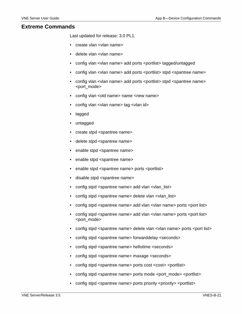
VNE Server User Guide App B—Device Configuration Commands
Extreme Commands
Last updated for release: 3.0 PL1.
• create vlan <vlan name>
• delete vlan <vlan name>
• config vlan <vlan name> add ports <portlist> tagged/untagged
• config vlan <vlan name> add ports <portlist> stpd <spantree name>
• config vlan <vlan name> add ports <portlist> stpd <spantree name> <port_mode>
• config vlan <old name> name <new name>
• config vlan <vlan name> tag <vlan id>
• tagged
• untagged
• create stpd <spantree name>
• delete stpd <spantree name>
• enable stpd <spantree name>
• enable stpd <spantree name>
• enable stpd <spantree name> ports <portlist>
• disable stpd <spantree name>
• config stpd <spantree name> add vlan <vlan_list>
• config stpd <spantree name> delete vlan <vlan_list>
• config stpd <spantree name> add vlan <vlan name> ports <port list>
• config stpd <spantree name> add vlan <vlan name> ports <port list> <port_mode>
• config stpd <spantree name> delete vlan <vlan name> ports <port list>
• config stpd <spantree name> forwarddelay <seconds>
• config stpd <spantree name> hellotime <seconds>
• config stpd <spantree name> maxage <seconds>
• config stpd <spantree name> ports cost <cost> <portlist>
• config stpd <spantree name> ports mode <port_mode> <portlist>
• config stpd <spantree name> ports priority <priority> <portlist>
VNE Server/Release 3.5 VNES-B-21
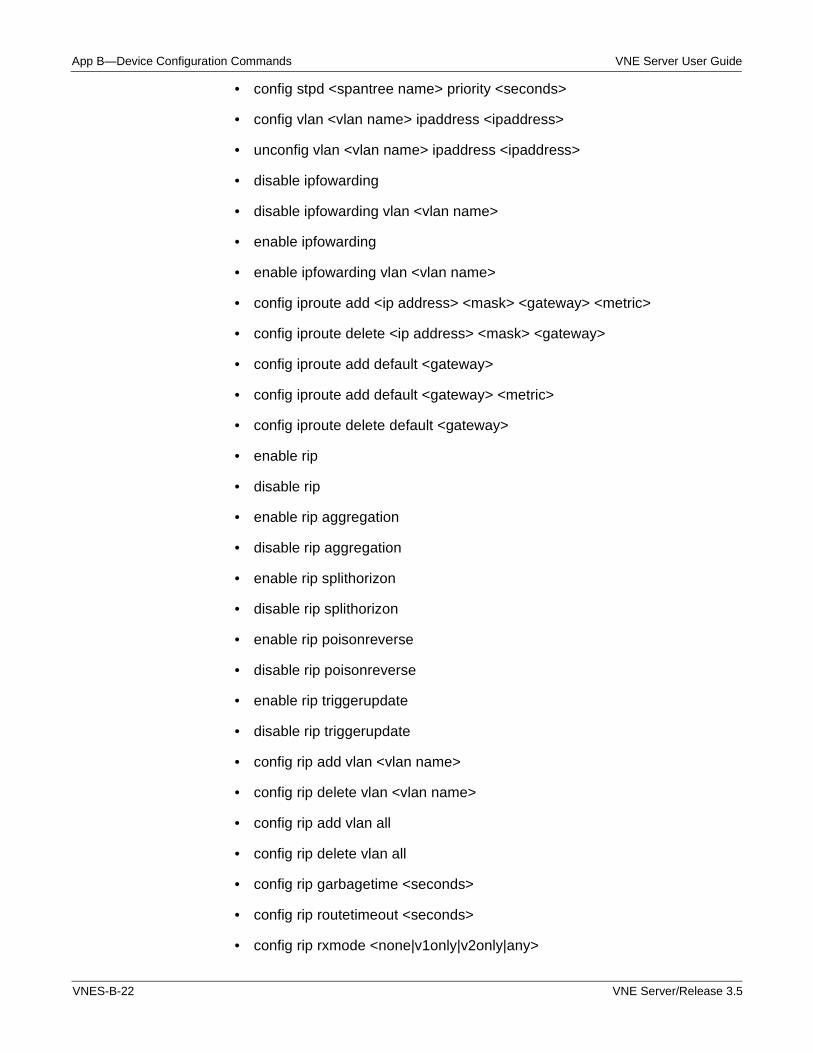
App B—Device Configuration Commands VNE Server User Guide
• config stpd <spantree name> priority <seconds>
• config vlan <vlan name> ipaddress <ipaddress>
• unconfig vlan <vlan name> ipaddress <ipaddress>
• disable ipfowarding
• disable ipfowarding vlan <vlan name>
• enable ipfowarding
• enable ipfowarding vlan <vlan name>
• config iproute add <ip address> <mask> <gateway> <metric>
• config iproute delete <ip address> <mask> <gateway>
• config iproute add default <gateway>
• config iproute add default <gateway> <metric>
• config iproute delete default <gateway>
• enable rip
• disable rip
• enable rip aggregation
• disable rip aggregation
• enable rip splithorizon
• disable rip splithorizon
• enable rip poisonreverse
• disable rip poisonreverse
• enable rip triggerupdate
• disable rip triggerupdate
• config rip add vlan <vlan name>
• config rip delete vlan <vlan name>
• config rip add vlan all
• config rip delete vlan all
• config rip garbagetime <seconds>
• config rip routetimeout <seconds>
• config rip rxmode <none|v1only|v2only|any>
VNES-B-22 VNE Server/Release 3.5
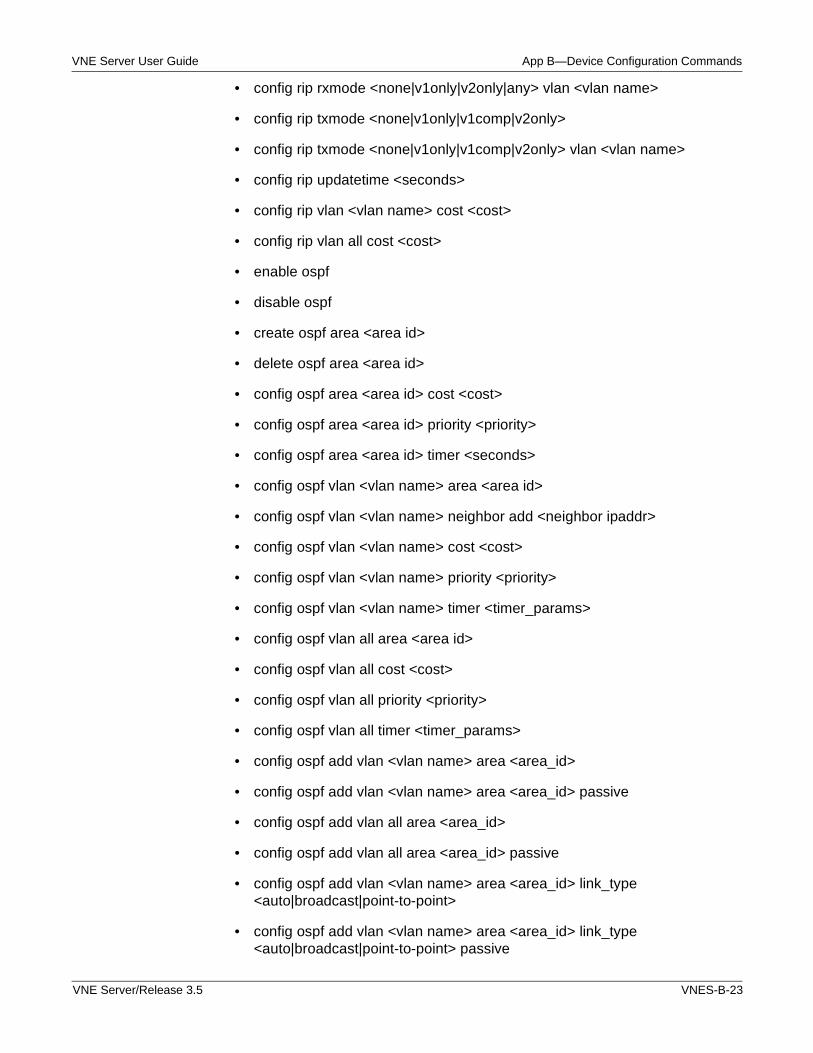
VNE Server User Guide App B—Device Configuration Commands
• config rip rxmode <none|v1only|v2only|any> vlan <vlan name>
• config rip txmode <none|v1only|v1comp|v2only>
• config rip txmode <none|v1only|v1comp|v2only> vlan <vlan name>
• config rip updatetime <seconds>
• config rip vlan <vlan name> cost <cost>
• config rip vlan all cost <cost>
• enable ospf
• disable ospf
• create ospf area <area id>
• delete ospf area <area id>
• config ospf area <area id> cost <cost>
• config ospf area <area id> priority <priority>
• config ospf area <area id> timer <seconds>
• config ospf vlan <vlan name> area <area id>
• config ospf vlan <vlan name> neighbor add <neighbor ipaddr>
• config ospf vlan <vlan name> cost <cost>
• config ospf vlan <vlan name> priority <priority>
• config ospf vlan <vlan name> timer <timer_params>
• config ospf vlan all area <area id>
• config ospf vlan all cost <cost>
• config ospf vlan all priority <priority>
• config ospf vlan all timer <timer_params>
• config ospf add vlan <vlan name> area <area_id>
• config ospf add vlan <vlan name> area <area_id> passive
• config ospf add vlan all area <area_id>
• config ospf add vlan all area <area_id> passive
• config ospf add vlan <vlan name> area <area_id> link_type <auto|broadcast|point-to-point>
• config ospf add vlan <vlan name> area <area_id> link_type <auto|broadcast|point-to-point> passive
VNE Server/Release 3.5 VNES-B-23
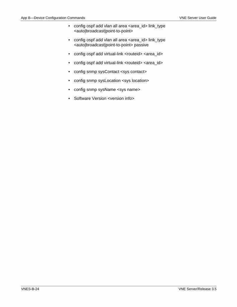
App B—Device Configuration Commands VNE Server User Guide
• config ospf add vlan all area <area_id> link_type <auto|broadcast|point-to-point>
• config ospf add vlan all area <area_id> link_type <auto|broadcast|point-to-point> passive
• config ospf add virtual-link <routeid> <area_id>
• config ospf add virtual-link <routeid> <area_id>
• config snmp sysContact <sys contact>
• config snmp sysLocation <sys location>
• config snmp sysName <sys name>
• Software Version <version info>
VNES-B-24 VNE Server/Release 3.5
VNE Server User Guide App B—Device Configuration Commands
Foundry Commands
Last updated for release: 3.0 PL1.
• interface <name/number> [multipoint|point-to-point|<other>]
• disable
• no ip address
• ip address <address> <mask> [ospf-ignore | ospf-passive | secondary]
• multilink-group <number>
• link-aggregate configure [system-priority <number>] | [port-priority <num>\ | [key <num>]
• ip rip v1-only
• ip rip v2-only
• ip rip v1-compatible-v2
• ip rip poison-reverse
• ip rip learn-default
• ip rip filter in <i j k ...>
• ip rip filter out <i j k...>
• bandwidth <kbps>
• speed-duplex <10-full | 10-half | 100-full | 100-half | auto>
• mtu <bytes>
• ip mtu <value>
• ip route-cache [cbus|flow|distributed]
• no ip route-cache [cbus|flow|distributed]
• ip router isis
• no ip router isis
• ip access-group {access-list-number | name} {in | out}
• isis metric <num>
• isis priority <num>
• isis password <password, can have blank space>
• isis circuit-type {level-1|level-2-only|level-1-2}
VNE Server/Release 3.5 VNES-B-25
App B—Device Configuration Commands VNE Server User Guide
• ip ospf cost <cost>
• ip ospf network [point-to-multipoint]
• ip ospf area <ip-addr|area-number>
• ip ospf network
• ip ospf dead-interval {seconds}
• ip ospf hello-interval {seconds}
• ip ospf passive
• ip ospf priority {priority}
• ip ospf retransmit-interval {seconds}
• ip ospf transmit-delay {seconds}
• atm pvc <vpi> <vci> cbr <pcr>
• atm pvc <vpi> <vci> vbr <pcr> <sbr> <mbs>
• atm pvc <vpi> <vci> ubr
• encapsulation frame-relay
• encapsulation frame-relay <ietf>
• frame-relay interface-dlci <dlci>
• frame-relay lmi-type {ansi|ccitt|lmi}
• frame-relay interface-dlci <dlci> lmi-type {ansi|ccitt|lmi}
• port-name <name string>
• ip tunnel <ip address> {pim|dvmrp|any}
• tunnel source <ip address|interface name>
• tunnel mpls traffic-eng affinity <properties> mask <mask>
• tunnel mpls traffic-eng affinity <properties>
• tunnel mpls traffic-eng autoroute announce
• no tunnel mpls traffic-eng autoroute announce
• tunnel mpls traffic-eng autoroute metric [absolute|relative] <metric>
• tunnel mpls traffic-eng autoroute metric <metric>
• tunnel mpls traffic-eng path-option <number> <dynamic|explicit name <path name|path number>>
VNES-B-26 VNE Server/Release 3.5
VNE Server User Guide App B—Device Configuration Commands
• tunnel mpls traffic-eng path-option <number> <dynamic|explicit name <path name|path number>> lockdown
• tunnel mpls traffic-eng priority <setup>
• tunnel mpls traffic-eng priority <setup> <hold>
• tunnel mpls traffic-eng fast-reroute
• mpls traffic-eng tunnels
• tunnel mode mpls traffic-eng
• ip rsvp bandwidth <interface kbps> <single flow kbps>
• ip rsvp bandwidth <interface kbps>
• mpls traffic-eng administrative-weight <weight>
• mpls traffic-eng attribute-flags <0x0 - 0xFFFFFFFF>
• mpls traffic-eng backup-path lsp-name
• mpls label protocol ldp
• mpls ip
• tag-switching ip
• mpls traffic-eng bandwidth <bandwidth>
• ip unnumbered <interface name>
• ip explicit-path {name WORD | identifier number} [{enable | disable}]
• next-address A.B.C.D
• shutdown
• standby [<group number>] ip [<ip address> [secondary]]
• standby [<group number>] mac-address <mac address>
• standby mac-refresh <seconds>
• standby name <group name>
• standby [<group number>] preempt priority <priority>
• standby [<group number>] preempt delay [<delay>] [minimum <delay>] [sync <delay>]
• standby [<group number>] preempt
• standby [<group number>] priority <priority>
VNE Server/Release 3.5 VNES-B-27
App B—Device Configuration Commands VNE Server User Guide
• standby [<group number>] timers [msec] <hello time> [msec] <hold time> [advertise <advertisement interval>]
• standby [<group number>] track <interface name> [<interface priority>]
• standby [<group number>] use-bia [scope interface]
• standby [group-number] authentication <string>
• standby delay [minimum <delay>] [reload <delay>]
• no standby redirects unknown
• standby redirects timers <advertisement-interval> <holddown-interval>
• ip policy route-map <map-tag>
• ip authentication mode eigrp <as-number> md5
• ip authentication key-chain eigrp <as-number> <key-chain>
• encapsulation dot1Q <vlan-id> [native]
• switchport\n
• switchport access vlan <vlan-id>
• switchport nonegotiate
• switchport broadcast <level>
• switchport protocol {ip | ipx | appletalk | other} {on | off | auto}
• switchport mode access
• switchport mode trunk
• switchport mode dynamic auto
• switchport mode dynamic desirable
• switchport trunk encapsulation {isl | dot1q | negotiate}
• switchport trunk native vlan <vlan-id>}
• switchport trunk allowed vlan <vlan-list>}
• switchport trunk pruning vlan <vlan-list>}
• spanning-tree
• no spanning-tree
• pvst-mode
• for "ip address <ip> <mask> [secondary |ospf-ignore | ospf-passive]"
VNES-B-28 VNE Server/Release 3.5
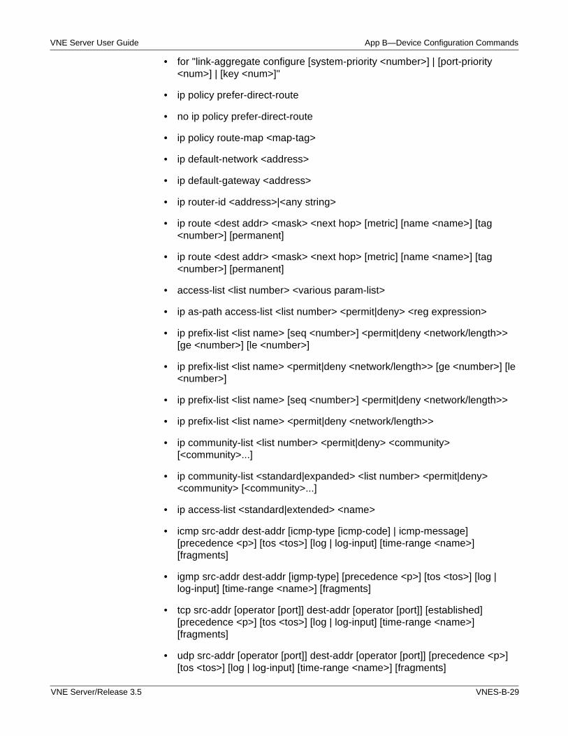
VNE Server User Guide App B—Device Configuration Commands
• for "link-aggregate configure [system-priority <number>] | [port-priority <num>] | [key <num>]"
• ip policy prefer-direct-route
• no ip policy prefer-direct-route
• ip policy route-map <map-tag>
• ip default-network <address>
• ip default-gateway <address>
• ip router-id <address>|<any string>
• ip route <dest addr> <mask> <next hop> [metric] [name <name>] [tag <number>] [permanent]
• ip route <dest addr> <mask> <next hop> [metric] [name <name>] [tag <number>] [permanent]
• access-list <list number> <various param-list>
• ip as-path access-list <list number> <permit|deny> <reg expression>
• ip prefix-list <list name> [seq <number>] <permit|deny <network/length>> [ge <number>] [le <number>]
• ip prefix-list <list name> <permit|deny <network/length>> [ge <number>] [le <number>]
• ip prefix-list <list name> [seq <number>] <permit|deny <network/length>>
• ip prefix-list <list name> <permit|deny <network/length>>
• ip community-list <list number> <permit|deny> <community> [<community>...]
• ip community-list <standard|expanded> <list number> <permit|deny> <community> [<community>...]
• ip access-list <standard|extended> <name>
• icmp src-addr dest-addr [icmp-type [icmp-code] | icmp-message] [precedence <p>] [tos <tos>] [log | log-input] [time-range <name>] [fragments]
• igmp src-addr dest-addr [igmp-type] [precedence <p>] [tos <tos>] [log | log-input] [time-range <name>] [fragments]
• tcp src-addr [operator [port]] dest-addr [operator [port]] [established] [precedence <p>] [tos <tos>] [log | log-input] [time-range <name>] [fragments]
• udp src-addr [operator [port]] dest-addr [operator [port]] [precedence <p>] [tos <tos>] [log | log-input] [time-range <name>] [fragments]
VNE Server/Release 3.5 VNES-B-29
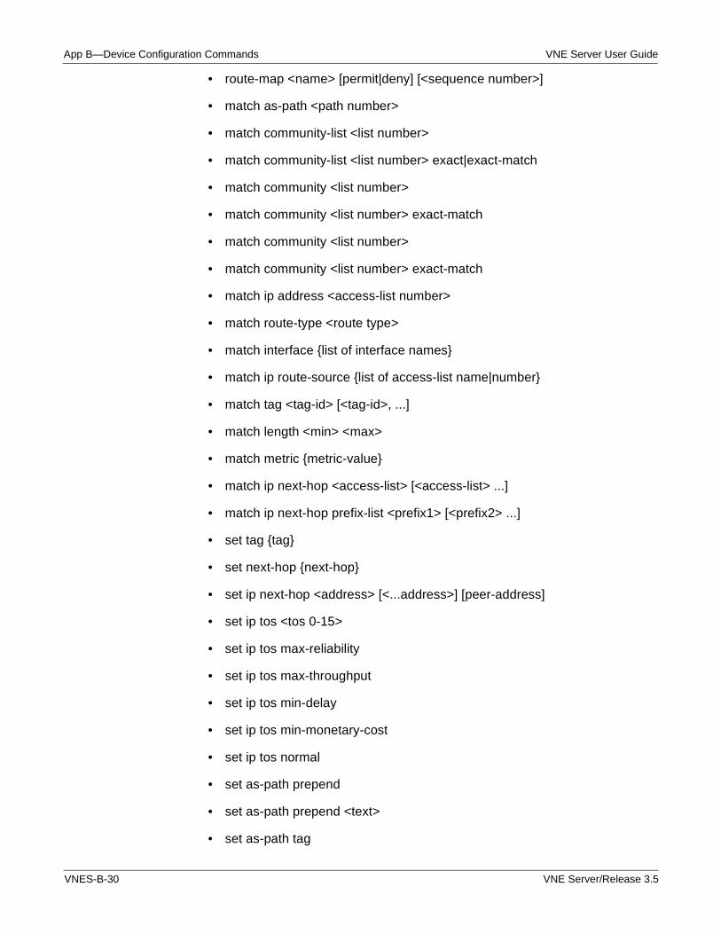
App B—Device Configuration Commands VNE Server User Guide
• route-map <name> [permit|deny] [<sequence number>]
• match as-path <path number>
• match community-list <list number>
• match community-list <list number> exact|exact-match
• match community <list number>
• match community <list number> exact-match
• match community <list number>
• match community <list number> exact-match
• match ip address <access-list number>
• match route-type <route type>
• match interface {list of interface names}
• match ip route-source {list of access-list name|number}
• match tag <tag-id> [<tag-id>, ...]
• match length <min> <max>
• match metric {metric-value}
• match ip next-hop <access-list> [<access-list> ...]
• match ip next-hop prefix-list <prefix1> [<prefix2> ...]
• set tag {tag}
• set next-hop {next-hop}
• set ip next-hop <address> [<...address>] [peer-address]
• set ip tos <tos 0-15>
• set ip tos max-reliability
• set ip tos max-throughput
• set ip tos min-delay
• set ip tos min-monetary-cost
• set ip tos normal
• set as-path prepend
• set as-path prepend <text>
• set as-path tag
VNES-B-30 VNE Server/Release 3.5
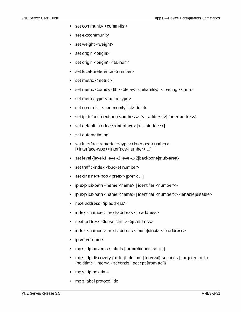
VNE Server User Guide App B—Device Configuration Commands
• set community <comm-list>
• set extcommunity
• set weight <weight>
• set origin <origin>
• set origin <origin> <as-num>
• set local-preference <number>
• set metric <metric>
• set metric <bandwidth> <delay> <reliability> <loading> <mtu>
• set metric-type <metric type>
• set comm-list <community list> delete
• set ip default next-hop <address> [<...address>] [peer-address]
• set default interface <interface> [<...interface>]
• set automatic-tag
• set interface <interface-type><interface-number> [<interface-type><interface-number> ...]
• set level {level-1|level-2|level-1-2|backbone|stub-area}
• set traffic-index <bucket number>
• set clns next-hop <prefix> [prefix ...]
• ip explicit-path <name <name> | identifier <number>>
• ip explicit-path <name <name> | identifier <number>> <enable|disable>
• next-address <ip address>
• index <number> next-address <ip address>
• next-address <loose|strict> <ip address>
• index <number> next-address <loose|strict> <ip address>
• ip vrf vrf-name
• mpls ldp advertise-labels [for prefix-access-list]
• mpls ldp discovery {hello {holdtime | interval} seconds | targeted-hello {holdtime | interval} seconds | accept [from acl]}
• mpls ldp holdtime
• mpls label protocol ldp
VNE Server/Release 3.5 VNES-B-31
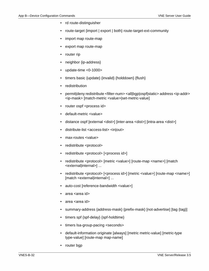
App B—Device Configuration Commands VNE Server User Guide
• rd route-distinguisher
• route-target {import | export | both} route-target-ext-community
• import map route-map
• export map route-map
• router rip
• neighbor {ip-address}
• update-time <0-1000>
• timers basic {update} {invalid} {holddown} {flush}
• redistribution
• permit|deny redistribute <filter-num> <all|bgp|ospf|static> address <ip-addr> <ip-mask> [match-metric <value>|set-metric-value]
• router ospf <process id>
• default-metric <value>
• distance ospf [external <dist>] [inter-area <dist>] [intra-area <dist>]
• distribute-list <access-list> <in|out>
• max-routes <value>
• redistribute <protocol>
• redistribute <protocol> [<process id>]
• redistribute <protocol> [metric <value>] [route-map <name>] [match <external|internal>] ...
• redistribute <protocol> [<process id>] [metric <value>] [route-map <name>] [match <external|internal>] ...
• auto-cost [reference-bandwidth <value>]
• area <area id>
• area <area id>
• summary-address {address-mask} {prefix-mask} [not-advertise] [tag {tag}]
• timers spf {spf-delay} {spf-holdtime}
• timers lsa-group-pacing <seconds>
• default-information originate [always] [metric metric-value] [metric-type type-value] [route-map map-name]
• router bgp
VNES-B-32 VNE Server/Release 3.5
VNE Server User Guide App B—Device Configuration Commands
• bgp redistribute-internal
• local-as <as-number>
• address-family vpnv4 [unicast | multicast]
• no auto-summary
• auto-summary
• no client-to-client-reflection
• client-to-client-reflection
• cluster-id {cluster-id | ip address}
• confederation identifier {autonomous-system}
• confederation peers as-number [... as-number]
• synchronization
• no synchronization
• timers bgp keepalive <decimal> holdtime <decimal>
• network <address> [mask <mask>] [weight <weight>] [route-map <map-name>]
• network <address> mask <mask>
• network <address>
• always-compare-med
• bgp default local-preference <value>
• default-metric <value>
• distance bgp <external> <internal> <local>
• distribute-list <access-list> <in|out>
• redistribute <protocol>
• redistribute <protocol> [<process id>]
• redistribute <protocol> [metric <value>] [route-map <name>] [match <external|internal>] ...
• redistribute <protocol> [<process id>] [metric <value>] [route-map <name>] [match <external|internal>] ...
• neighbor <ip addr|peer group name> <params.....>
• neighbor <peer group name>
VNE Server/Release 3.5 VNES-B-33
App B—Device Configuration Commands VNE Server User Guide
• maximum-paths <value>
• max-routes <value>
• aggregate-address <address> <mask> [as-set] [summary-only] [suppress-map <map-name>] [advertise-map <map-name>] [attribute-map <map-name>]
• no fast-external-failover
• bgp fast-external-failover
• router-id <ip address>
• router isis
• is-type {level-1, level-2-only, level-1-2}
• set-overload-bit
• lsp-mtu {bytes}
• max-lsp-lifetime {lifetime}
• summary-address address mask {level-1 | level-1-2 | level-2}
• no hello-padding [multi-point|point-to-point]
• hello-padding {multi-point|point-to-point}
• net <net>
• distance <distance> [<address> <mask> [<access-list>]]
• maximum-paths <value>
• metric-style wide
• metric-style wide [level-1 | level-2-only]
• redistribute <protocol>
• redistribute <protocol> [<process id>]
• redistribute <protocol> [metric <value>] [route-map <name>] [match <external|internal>] ...
• redistribute <protocol> [<process id>] [metric <value>] [route-map <name>] [match <external|internal>] ...
• redistribute isis ip <level> into <level> [distribute-list <number> | metric-style wide>]
• mpls traffic-eng isis-level <level>
• mpls traffic-eng <level>
VNES-B-34 VNE Server/Release 3.5
VNE Server User Guide App B—Device Configuration Commands
• mpls traffic-eng <level>
• spf-interval <min-interval>
• lsp-refresh-interval <seconds>
• lsp-gen-interval <min-interval>
• max-area-addresses <num-addresses>
• area-password <password>
• domain-password <password>
• hostname <name>
• mpls traffic-eng tunnels
• ver <version>
• snmp-server community <string> [view <view-name>] [ro|rw] [<access-list number>]
• snmp-server view <view-name> <oid-tree> {included|excluded}
• snmp-server host <host-addr> [traps|informs] [version {1 | 2c | 3 [auth | noauth | priv]}] <community-string> [udp-port <port>] [<notification-type>]
• snmp-server enable traps [<notification-type>]
• snmp-server queue-length <length>
• snmp-server packetsize <byte-count>
• snmp-server manager session-timeout <seconds>
• snmp-server trap-source <interface>
• no snmp-server system-shutdown
• snmp-server system-shutdown
• no snmp-server manager
• snmp-server manager
• snmp-server chassis-id <text>
• snmp-server location <text>
• snmp-server contact <text>
• logging <host-name>
• logging buffered [<buffer-size> | <level>]
• no logging console
VNE Server/Release 3.5 VNES-B-35
App B—Device Configuration Commands VNE Server User Guide
• logging console <level>
• logging facility <facility-type>
• logging monitor <severity-level>
• no logging on
• logging on
• logging source-interface <interface-type interface-number>
• logging trap <level>
• spanning-tree [forward delay <num>] [hello-time <num>] [priority <num>] (global cmd)
• vlan <num> name <name> by port
• vlan <num> by port
• super-span
• tagged ethernet|pos|atm <portnumber> [to <num> [ethernet|pos|atm <num> [....]]]
• untagged ethernet|pos|atm <portnumber> [to <num> [ethernet|pos|atm <num> [....]]]
• priority
• router-interface ve <num>
• spanning-tree [forward delay <num>] [hello-time <num>] [priority <num>] [max-age <num>] (vlan cmd)
• spanning-tree single [forward delay <num>] [hello-time <num>] [priority <num>] [max-age <num>] (vlan cmd)
• spanning-tree single 802-1.w [forward delay <num>] [hello-time <num>] [priority <num>] [max-age <num>] (vlan cmd)
• spanning-tree 802-1.w [forward delay <num>] [hello-time <num>] [priority <num>] [max-age <num>] (vlan cmd)
• spanning-tree single rstp [forward delay <num>] [hello-time <num>] [priority <num>] [max-age <num>] (vlan cmd)
VNES-B-36 VNE Server/Release 3.5
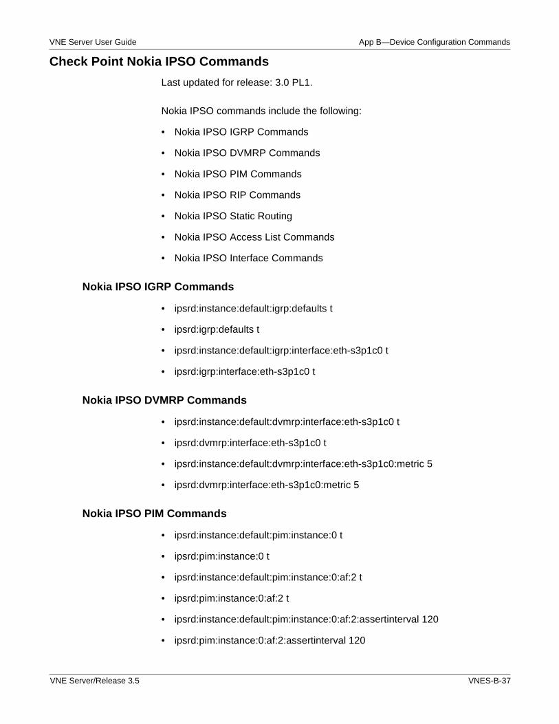
VNE Server User Guide App B—Device Configuration Commands
Check Point Nokia IPSO Commands
Last updated for release: 3.0 PL1.
Nokia IPSO commands include the following:
• Nokia IPSO IGRP Commands
• Nokia IPSO DVMRP Commands
• Nokia IPSO PIM Commands
• Nokia IPSO RIP Commands
• Nokia IPSO Static Routing
• Nokia IPSO Access List Commands
• Nokia IPSO Interface Commands
Nokia IPSO IGRP Commands
• ipsrd:instance:default:igrp:defaults t
• ipsrd:igrp:defaults t
• ipsrd:instance:default:igrp:interface:eth-s3p1c0 t
• ipsrd:igrp:interface:eth-s3p1c0 t
Nokia IPSO DVMRP Commands
• ipsrd:instance:default:dvmrp:interface:eth-s3p1c0 t
• ipsrd:dvmrp:interface:eth-s3p1c0 t
• ipsrd:instance:default:dvmrp:interface:eth-s3p1c0:metric 5
• ipsrd:dvmrp:interface:eth-s3p1c0:metric 5
Nokia IPSO PIM Commands
• ipsrd:instance:default:pim:instance:0 t
• ipsrd:pim:instance:0 t
• ipsrd:instance:default:pim:instance:0:af:2 t
• ipsrd:pim:instance:0:af:2 t
• ipsrd:instance:default:pim:instance:0:af:2:assertinterval 120
• ipsrd:pim:instance:0:af:2:assertinterval 120
VNE Server/Release 3.5 VNES-B-37
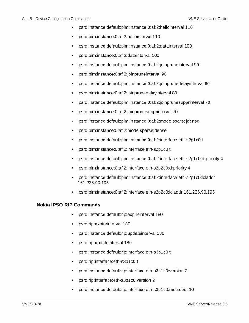
App B—Device Configuration Commands VNE Server User Guide
• ipsrd:instance:default:pim:instance:0:af:2:hellointerval 110
• ipsrd:pim:instance:0:af:2:hellointerval 110
• ipsrd:instance:default:pim:instance:0:af:2:datainterval 100
• ipsrd:pim:instance:0:af:2:datainterval 100
• ipsrd:instance:default:pim:instance:0:af:2:joinpruneinterval 90
• ipsrd:pim:instance:0:af:2:joinpruneinterval 90
• ipsrd:instance:default:pim:instance:0:af:2:joinprunedelayinterval 80
• ipsrd:pim:instance:0:af:2:joinprunedelayinterval 80
• ipsrd:instance:default:pim:instance:0:af:2:joinprunesupprinterval 70
• ipsrd:pim:instance:0:af:2:joinprunesupprinterval 70
• ipsrd:instance:default:pim:instance:0:af:2:mode sparse|dense
• ipsrd:pim:instance:0:af:2:mode sparse|dense
• ipsrd:instance:default:pim:instance:0:af:2:interface:eth-s2p1c0 t
• ipsrd:pim:instance:0:af:2:interface:eth-s2p1c0 t
• ipsrd:instance:default:pim:instance:0:af:2:interface:eth-s2p1c0:drpriority 4
• ipsrd:pim:instance:0:af:2:interface:eth-s2p2c0:drpriority 4
• ipsrd:instance:default:pim:instance:0:af:2:interface:eth-s2p1c0:lcladdr 161.236.90.195
• ipsrd:pim:instance:0:af:2:interface:eth-s2p2c0:lcladdr 161.236.90.195
Nokia IPSO RIP Commands
• ipsrd:instance:default:rip:expireinterval 180
• ipsrd:rip:expireinterval 180
• ipsrd:instance:default:rip:updateinterval 180
• ipsrd:rip:updateinterval 180
• ipsrd:instance:default:rip:interface:eth-s3p1c0 t
• ipsrd:rip:interface:eth-s3p1c0 t
• ipsrd:instance:default:rip:interface:eth-s3p1c0:version 2
• ipsrd:rip:interface:eth-s3p1c0:version 2
• ipsrd:instance:default:rip:interface:eth-s3p1c0:metricout 10
VNES-B-38 VNE Server/Release 3.5
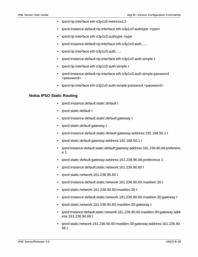
VNE Server User Guide App B—Device Configuration Commands
• ipsrd:rip:interface:eth-s3p1c0:metricout 2
• ipsrd:instance:default:rip:interface:eth-s3p1c0:authtype <type>
• ipsrd:rip:interface:eth-s3p1c0:authtype <type
• ipsrd:instance:default:rip:interface:eth-s3p1c0:auth......
• ipsrd:rip:interface:eth-s3p1c0:auth......
• ipsrd:instance:default:rip:interface:eth-s3p1c0:auth:simple t
• ipsrd:rip:interface:eth-s3p1c0:auth:simple t
• ipsrd:instance:default:rip:interface:eth-s3p1c0:auth:simple:password <password>
• ipsrd:rip:interface:eth-s3p1c0:auth:simple:password <password>
Nokia IPSO Static Routing
• ipsrd:instance:default:static:default t
• ipsrd:static:default t
• ipsrd:instance:default:static:default:gateway t
• ipsrd:static:default:gateway t
• ipsrd:instance:default:static:default:gateway:address:192.168.50.1 t
• ipsrd:static:default:gateway:address:192.168.50.1 t
• ipsrd:instance:default:static:default:gateway:address:161.236.90.66:preference 1
• ipsrd:static:default:gateway:address:161.236.90.66:preference 1
• ipsrd:instance:default:static:network:161.236.90.60 t
• ipsrd:static:network:161.236.90.60 t
• ipsrd:instance:default:static:network:161.236.90.60:masklen:30 t
• ipsrd:static:network:161.236.90.60:masklen:30 t
• ipsrd:instance:default:static:network:161.236.90.60:masklen:30:gateway t
• ipsrd:static:network:161.236.90.60:masklen:30:gateway t
• ipsrd:instance:default:static:network:161.236.90.60:masklen:30:gateway:address:161.236.90.66 t
• ipsrd:static:network:161.236.90.60:masklen:30:gateway:address:161.236.90.66 t
VNE Server/Release 3.5 VNES-B-39
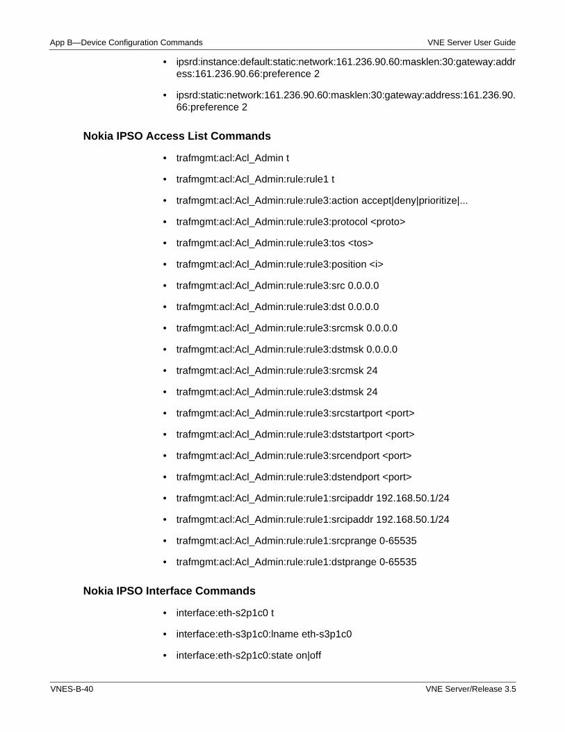
App B—Device Configuration Commands VNE Server User Guide
• ipsrd:instance:default:static:network:161.236.90.60:masklen:30:gateway:address:161.236.90.66:preference 2
• ipsrd:static:network:161.236.90.60:masklen:30:gateway:address:161.236.90.66:preference 2
Nokia IPSO Access List Commands
• trafmgmt:acl:Acl_Admin t
• trafmgmt:acl:Acl_Admin:rule:rule1 t
• trafmgmt:acl:Acl_Admin:rule:rule3:action accept|deny|prioritize|...
• trafmgmt:acl:Acl_Admin:rule:rule3:protocol <proto>
• trafmgmt:acl:Acl_Admin:rule:rule3:tos <tos>
• trafmgmt:acl:Acl_Admin:rule:rule3:position <i>
• trafmgmt:acl:Acl_Admin:rule:rule3:src 0.0.0.0
• trafmgmt:acl:Acl_Admin:rule:rule3:dst 0.0.0.0
• trafmgmt:acl:Acl_Admin:rule:rule3:srcmsk 0.0.0.0
• trafmgmt:acl:Acl_Admin:rule:rule3:dstmsk 0.0.0.0
• trafmgmt:acl:Acl_Admin:rule:rule3:srcmsk 24
• trafmgmt:acl:Acl_Admin:rule:rule3:dstmsk 24
• trafmgmt:acl:Acl_Admin:rule:rule3:srcstartport <port>
• trafmgmt:acl:Acl_Admin:rule:rule3:dststartport <port>
• trafmgmt:acl:Acl_Admin:rule:rule3:srcendport <port>
• trafmgmt:acl:Acl_Admin:rule:rule3:dstendport <port>
• trafmgmt:acl:Acl_Admin:rule:rule1:srcipaddr 192.168.50.1/24
• trafmgmt:acl:Acl_Admin:rule:rule1:srcipaddr 192.168.50.1/24
• trafmgmt:acl:Acl_Admin:rule:rule1:srcprange 0-65535
• trafmgmt:acl:Acl_Admin:rule:rule1:dstprange 0-65535
Nokia IPSO Interface Commands
• interface:eth-s2p1c0 t
• interface:eth-s3p1c0:lname eth-s3p1c0
• interface:eth-s2p1c0:state on|off
VNES-B-40 VNE Server/Release 3.5
VNE Server User Guide App B—Device Configuration Commands
• interface:eth-s2p1c0:ipaddr:161.236.90.130 t
• interface:eth-s2p1c0:ipaddr:161.236.90.130:mask 26
• interface:eth-s3p1c0:acl:input Acl_Admin
• interface:eth-s3p1c0:acl:output Acl_Admin
• ifphys:eth-s2p1:duplicity full|half
• ifphys:eth-s2p1:state on|off
• ifphys:eth-s2p2:speed 100M
VNE Server/Release 3.5 VNES-B-41
App B—Device Configuration Commands VNE Server User Guide
Juniper ERX JUNOSe Commands
Last updated for release: 3.0 PL1.
Juniper JUNOSe commands include the following:
• JUNOSe AAA Commands
• JUNOSe Interface Commands
• JUNOSe Multicast Interface Commands
• JUNOSe Multicast Commands
• JUNOSe NAT Commands
• JUNOSe Node Commands
• JUNOSe QoS Commands
• JUNOSe Routing Commands
VNES-B-42 VNE Server/Release 3.5
VNE Server User Guide App B—Device Configuration Commands
JUNOSe AAA Commands
• aaa newmodel
• enable secret [level level] {password | [encryption-type] encrypted-password}
• enable password [level level] {password | [encryption-type] encrypted-password}
• [no] aaa authentication arap { default | list-name } <method1> [<method2> ...]
• [no] aaa authentication dot1x { default | list-name } <method1> [<method2> ...]
• [no] aaa authentication sbgp { default | list-name } <method1> [<method2> ...]
• [no] aaa authentication login { default | list-name } <method1> [<method2> ...]
• [no] aaa authentication ppp { default | list-name } <method1> [<method2> ...]
• [no] aaa authentication enable default <method1> [<method2> ...]
• [no] aaa authentication attempts login <number>
• [no] aaa authentication password-prompt <text-string>
• [no] aaa authentication username-prompt <text-string>
• [no] aaa nas redirected-station
• aaa authentication banner <d>text<d>
• no aaa authentication banner
• aaa authentication fail-message <d>text<d>
• no aaa authentication banner
• no ip trigger-authentication
• ip trigger-authentication [timeout <seconds>] [port <port>]
• aaa authorization {exec | commands level} {default | list-name} method1 [method2...]
• aaa authorization config-commands
• no aaa authorization config-commands
• aaa authorization reverse-access group radius JUNOSe Interface Commands
• interface <name/number> [multipoint|point-to-point|<other>]
VNE Server/Release 3.5 VNES-B-43
App B—Device Configuration Commands VNE Server User Guide
• ppp authentication [virtual-router rtrName] pap [chap] | chap [pap]
• no ppp authentication
• no ip address
• ip address <address> <mask>
• ip vrf forwarding vrf-name
• ip rip send version off
• ip rip send version [1]
• ip rip send version [1] [2]
• ip rip receive version off
• ip rip receive version [1]
• ip rip receive version [1] [2]
• clock rate <rate> // in Hz
• bandwidth <kbps>
• speed <Mbps>
• duplex automatically negotiate
• duplex full\n
• duplex half\n
• [ip|pos|frame-relay] description <text>
• mtu <bytes>
• ip mtu <value>
• ip router isis <process tag>
• ip router isis
• isis metric <defaultMetric> [ level-1 | level-2 ]
• isis circuit-type {level-1|level-2-only|level-1-2}
• isis csnp-interval {seconds} {level-1|level-2}
• isis hello-interval {seconds} {level-1|level-2}
• isis hello-multiplier {seconds} {level-1|level-2}
• isis priority {priority} {level-1|level-2}
• isis lsp-interval {milliseconds}
VNES-B-44 VNE Server/Release 3.5
VNE Server User Guide App B—Device Configuration Commands
• isis retransmit-interval {milliseconds}
• isis retransmit-throttle-interval {milliseconds}
• ip ospf cost <cost>
• ip ospf network { broadcast | non-broadcast | point-to-point }
• ip ospf dead-interval {seconds}
• ip ospf hello-interval {seconds}
• ip ospf priority {priority}
• ip ospf retransmit-interval {seconds}
• ip ospf transmit-delay {seconds}
• ip ospf authentication-none
• ip ospf authentication message-digest
• ip ospf authentication message-digest
• no ip split-horizon
• ip split-horizon
• atm pvc <vcd> <vpi> <vci> encapsulation [cbr cbr | peak [average burst [rt]]] [oam [seconds|cc [segment | end-to-end] {source|sink|both}]] [inArp [minutes]]
• atm pvc encapsulation [cbr cbr | peak [average burst [rt]]]
• encapsulation {bridge1483 [mac-address <mac-address>]|hdlc|ietf|mlppp|ppp|pppoe|smds-trunk|vlan}
• frame-relay interface-dlci <dlci> ietf
• tunnel source <ip address|interface name>
• {ip rsvp | mpls} bandwidth <kbps>
• mpls traffic-eng administrative-weight <weight>
• mpls traffic-eng attribute-flags <0x0 - 0xFFFFFFFF>
• mpls ldp profile <profileName>
• ip unnumbered <interface name>
• shutdown
• isis mesh-group [<number>|blocked]
• ip nat {inside | outside}
VNE Server/Release 3.5 VNES-B-45
App B—Device Configuration Commands VNE Server User Guide
• bridge-group <bridgeGroupName> [subscriber-trunk|snmp-trap link-status|learn <addressCount>]
• tunnel checksum
• clock source {line | internal { chassis | module }}
• loopback {diagnostic | line | internal}
• tunnel destination <ip address|hostname> | {nada}
JUNOSe Multicast Interface Commands
• interface <name/number> [multipoint|point-to-point|<other>]
• ip pim {sparse-mode | sparse-dense-mode | dense-mode}
• ip dvmrp accept-filter listName1 [distance] neighbor-list listName2
• ip dvmrp auto-summary
• ip dvmrp metric-offset [in | out] <increment>
• ip dvmrp summary-address <summary-address> <mask> [metric <value>]
• ip dvmrp unicast-routing
• ip igmp access-group <access-list-number>
• ip igmp immediate-leave
• ip igmp last-member-query-interval <interval>
• ip igmp query-interval <seconds>
• ip igmp query-max-response-time <seconds>
• ip igmp static-group <group-address>
• ip igmp version {3 | 2 | 1}
JUNOSe Multicast Commands
• ip multicast-routing
• ip multicast-routing disable-rpf-check ipAccessList
• ip multicast-routing permanent-mroute accessListName
• ip pim rp-address <rp-address> [access-list] [override]
• ip pim send-rp-announce <interfaceType> <interfaceSpecifier> scope <ttl-value> [group-list <access-list>] [interval <seconds>]
VNES-B-46 VNE Server/Release 3.5
VNE Server User Guide App B—Device Configuration Commands
• ip pim send-rp-discovery scope <ttl-value> [<interfaceType> <interfaceSpecifier>]
• ip pim ssm {default | range <access-list>}
• ip pim spt-threshold {<kbps> | infinity} [group-list <access-list>]
• ip dvmrp routehog-notification <route-count>
• ip dvmrp route-limit <count>
JUNOSe NAT Commands
• ip nat translation [max-entries number] {timeout | udp-timeout | dns-timeout | tcp-timeout | finrst-timeout | icmp-timeout } seconds
• ip nat pool name start-ip end-ip {netmask netmask | prefix-length prefix-length}
• ip nat inside source list accesListName pool poolName [overload]
• ip nat outside source {list {access-list-number | access-list-name} | route-map name} pool pool-name [mapping-id map-name | vrf name] [add-route]
• ip nat inside source [tcp | udp] static local-ip [localPort] global-ip [globalPort]
• ip nat outside source [tcp | udp] static global-ip [globalPort] local-ip [localPort]
JUNOSe Node Commands
• hostname <name>
• ip domain-name <name>
• ip router-id ipAddress
• ip router-id [vrfName] ipAddress
• snmp-server community <string> [view <view-name>] [ro|rw|admin] [<access-list number>]
• snmp-server host <ipAddress> [ version { 1 | 2c | 3 } ] <communityString> [ udp-port <port> ] [ trapCategory ]* [ <trapFilters> trapFilter ]
• snmp-server enable traps [<notification-type>]
• snmp-server packetsize <byte-count>
• snmp-server trap-source <interface> <interface specifier>
• snmp-server location <text>
• snmp-server contact <text>
VNE Server/Release 3.5 VNES-B-47
App B—Device Configuration Commands VNE Server User Guide
• service timestamps <message-type> [uptime]
• boot system <relFileName>
JUNOSe QoS Commands
• interface <name/number> [multipoint|point-to-point|<other>]
• traffic-class trafficClassName [classifier-group claclName] [precedence precedence]
• [ip|ipv6|frame-relay|gre-tunnel|l2tp|mpls|vlan] policy-list <policyListName>
• color {green|yellow|red} [classifier-group claclName] [precedence precValue]
• filter [classifier-group claclName] [precedence precValue]
• log [classifier-group claclName] [precedence precValue]
• mark-de <de> [classifier-group claclName] [precedence precValue]
• mark-exp <exp> [classifier-group claclName] [precedence precValue]
• mark-user-priority <priority> [classifier-group claclName] [precedence precValue]
• next-hop nextHopAddress [classifier-group claclName] [precedence precValue]
• rate-limit-profile profileName [classifier-group claclName] [precedence precValue]
• traffic-class className [classifier-group claclName] [precedence precValue]
• user-packet-class userPacketClassValue [classifier-group claclName] [precedence precValue]
• next-interface interfaceType interfaceNumber [ next-hop nextHop ] [ classifier-group claclName ] [ precedence precValue ]
• forward [ interface interfaceType interfaceSpecifier [ next-hop nextHop [ ignore-default-route ] ] | next-hop nextHop [ virtual-router vrName ] [ ignore-default-route ] ] [ order orderValue ] [ classifier-group claclName ] [ precedence precValue ]
JUNOSe Routing Commands
• ip route [ vrf <vrfName> ] { <ipAddress> <ipMask> { <ipNextHop> [ <interfaceType> <interfaceSpecifier> ] | <interfaceType> <interfaceSpecifier> } | parent-router <interfaceType> <interfaceSpecifier> } [ <distance> ] [ <tag tagVal> ] [ permanent ] [ verify rtr <rtrIndex> [ last-resort ] ]
VNES-B-48 VNE Server/Release 3.5
VNE Server User Guide App B—Device Configuration Commands
• access-list <accessListName> <various param-list>
• ip as-path access-list <list number> <permit|deny> <reg expression>
• ip prefix-list <list name> [seq <number>] <permit|deny <network/length>> [ge <number>] [le <number>]
• ip community-list <list name> <permit|deny> <community> [<community>...]
• route-map <name> [permit|deny] [<sequence number>]
• match as-path <path number>
• match community listName [listName]*
• match community listName [listName]* exact-match
• match extcommunity listName [listName]*
• match extcommunity listName [listName]* exact-match
• match ip address <access-list number>
• match ip address <access-list number>
• match ip address <access-list number>
• match ip address any
• match route-type <route type>
• match tag <tag-id> [<tag-id>, ...] "
• match metric {metric-value}
• match ip next-hop <access-list> [<access-list> ...]
• match ip next-hop prefix-list <prefix1> [<prefix2> ...]
• match ip next-hop prefix-list <prefix1> [<prefix2> ...]
• set tag {tag}
• set ip next-hop <address> [<...address>] [peer-address]
• set as-path prepend
• set as-path prepend {list listName | <asPathNumber> [<asPathNumber>]*]
• set community <comm-list>
• set extcommunity
• set weight <weight>
• set origin <origin>
VNE Server/Release 3.5 VNES-B-49
App B—Device Configuration Commands VNE Server User Guide
• set local-preference <number>
• set metric <metric>
• set metric-type <metric type>
• set comm-list <community list> delete
• set automatic-tag
• set level {level-1|level-2|level-1-2|backbone|stub-area}
• set distance <distance>
• ip explicit-path <name <name> | identifier <number>>
• ip explicit-path <name <name> | identifier <number>> <enable|disable>
• next-address <ip address>
• index <number> next-address <ip address>
• ip vrf vrf-name
• mpls ldp advertise-labels {host-only|for routeAccessList [to neighborAccessList]}
• mpls [traffic-eng tunnels] [disable]
• mpls ldp session retries <retryNum>
• rd route-distinguisher
• route-target {import | export | both} route-target-ext-community
• import map route-map
• export map route-map
• router rip
• network <address>
• network <address>
• neighbor {ip-address}
• timers {update} {invalid} {holddown} {flush}
• version {1|2}
• no auto-summary
• auto-summary
• default-metric <value>
VNES-B-50 VNE Server/Release 3.5
VNE Server User Guide App B—Device Configuration Commands
• distance <distance>
• distribute-list <access-list> <in|out>
• maximum-paths <value>
• no passive-interface <interface>
• passive-interface <interface>
• redistribute {protocol |ospf match internal [external [1|2]] ospf match external [1|2] [internal]} [metric absoluteValue | route-map mapTag]* ...
• router ospf <process id> [vrf vrfName]
• set-overload-bit [on-startup <seconds>]
• network <address> <wildcard mask> area <area id>
• distance ospf [external <dist>] [inter-area <dist>] [intra-area <dist>]
• distribute-list <access-list> <in|out>
• maximum-paths <value>
• no passive-interface <interface>
• passive-interface <interface>
• ospf auto-cost reference-bandwidth <value>
• area <area id>
• summary-address <address> <mask>
• timers spf {spf-holdtime}
• neighbor {ip-address} [priority {number}] [poll-interval {seconds}]
• default-information originate [always] [metric metric-value] [metric-type type-value] [route-map map-name]
• router bgp <as>
• bgp redistribute-internal
• set-overload-bit [on-startup <seconds>]
• no auto-summary
• auto-summary
• no bgp client-to-client reflection
• bgp client-to-client reflection
• bgp cluster-id {cluster-id}
VNE Server/Release 3.5 VNES-B-51
App B—Device Configuration Commands VNE Server User Guide
• bgp cluster-id {cluster-id}
• bgp confederation identifier {autonomous-system}
• bgp confederation peers as-number [... as-number]
• bgp confederation peers filter-list filterList
• synchronization
• no synchronization
• timers bgp {keepalive}
• timers bgp {keepalive} {holdtime}
• network <address> [mask <mask>] [weight <weight>] [route-map <map-name>] [backdoor]
• bgp always-compare-med
• bgp default local-preference <value>
• distance bgp <external> <internal> <local>
• distribute-list <access-list> <in|out> [interfaceType interfaceSpecifier]
• neighbor
• neighbor <peer group name> peer-group
• neighbor <ip address> peer-group <peer group name>
• maximum-paths <value>
• no bgp fast-external-fallover
• bgp fast-external-fallover
• bgp router-id <ip address>
• address-family vpnv4 [unicast]
• address-family ipv4 [unicast] vrf vrf-name
• router isis [<process id>]
• router isis
• set-overload-bit [on-startup <seconds>]
• is-type {level-1, level-2-only, level-1-2} "
• lsp-mtu {bytes}
• max-lsp-lifetime {lifetime}
VNES-B-52 VNE Server/Release 3.5
VNE Server User Guide App B—Device Configuration Commands
• summary-address address mask {level-1 | level-1-2 | level-2}
• net <net>
• distribute-list <access-list> <in|out>
• distribute-list <access-list> <in|out> [<interface|<proto [as num]>]
• maximum-paths <value>
• metric-style {wide|narrow|transition} [level-1|level-2|level-1-2]
• no passive-interface <interface>
• mpls traffic-eng <level>
• mpls traffic-eng <level>
• spf-interval [level-1|level-2] <seconds>
• lsp-refresh-interval <seconds>
• lsp-gen-interval [level-1|level-2] <seconds>
VNE Server/Release 3.5 VNES-B-53

App B—Device Configuration Commands VNE Server User Guide
VNES-B-54 VNE Server/Release 3.5
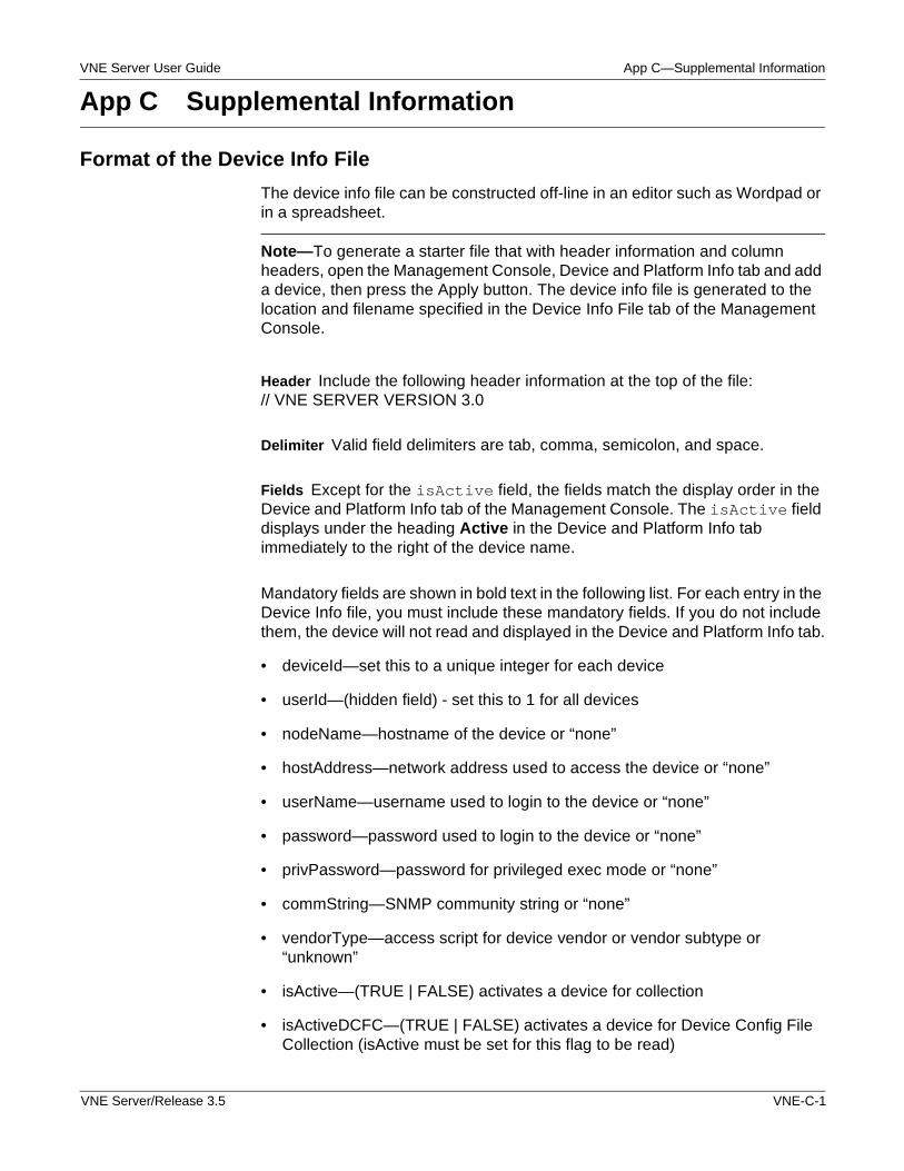
VNE Server User Guide App C—Supplemental Information
App C Supplemental Information
Format of the Device Info File
The device info file can be constructed off-line in an editor such as Wordpad or in a spreadsheet.
Note—To generate a starter file that with header information and column headers, open the Management Console, Device and Platform Info tab and add a device, then press the Apply button. The device info file is generated to the location and filename specified in the Device Info File tab of the Management Console.
Header Include the following header information at the top of the file: // VNE SERVER VERSION 3.0
Delimiter Valid field delimiters are tab, comma, semicolon, and space.
Fields Except for the isActive field, the fields match the display order in the Device and Platform Info tab of the Management Console. The isActive field displays under the heading Active in the Device and Platform Info tab immediately to the right of the device name.
Mandatory fields are shown in bold text in the following list. For each entry in the Device Info file, you must include these mandatory fields. If you do not include them, the device will not read and displayed in the Device and Platform Info tab.
• deviceId—set this to a unique integer for each device
• userId—(hidden field) - set this to 1 for all devices
• nodeName—hostname of the device or “none”
• hostAddress—network address used to access the device or “none”
• userName—username used to login to the device or “none”
• password—password used to login to the device or “none”
• privPassword—password for privileged exec mode or “none”
• commString—SNMP community string or “none”
• vendorType—access script for device vendor or vendor subtype or “unknown”
• isActive—(TRUE | FALSE) activates a device for collection
• isActiveDCFC—(TRUE | FALSE) activates a device for Device Config File Collection (isActive must be set for this flag to be read)
VNE Server/Release 3.5 VNE-C-1
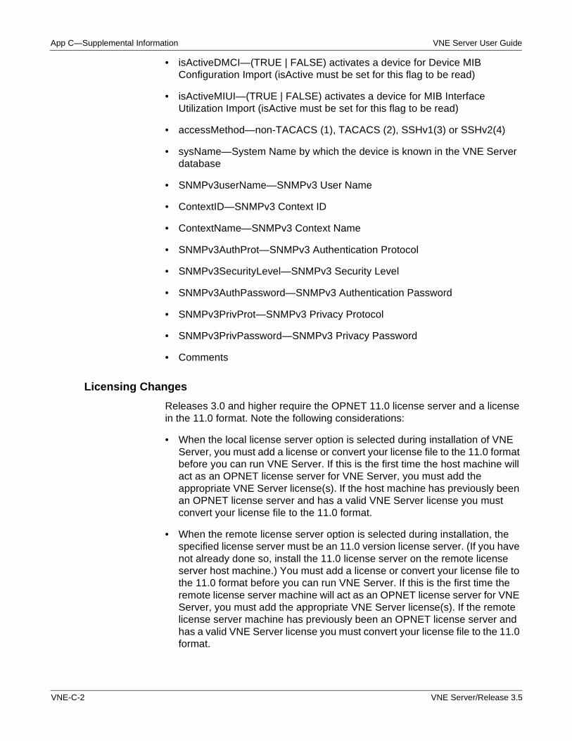
App C—Supplemental Information VNE Server User Guide
• isActiveDMCI—(TRUE | FALSE) activates a device for Device MIB Configuration Import (isActive must be set for this flag to be read)
• isActiveMIUI—(TRUE | FALSE) activates a device for MIB Interface Utilization Import (isActive must be set for this flag to be read)
• accessMethod—non-TACACS (1), TACACS (2), SSHv1(3) or SSHv2(4)
• sysName—System Name by which the device is known in the VNE Server database
• SNMPv3userName—SNMPv3 User Name
• ContextID—SNMPv3 Context ID
• ContextName—SNMPv3 Context Name
• SNMPv3AuthProt—SNMPv3 Authentication Protocol
• SNMPv3SecurityLevel—SNMPv3 Security Level
• SNMPv3AuthPassword—SNMPv3 Authentication Password
• SNMPv3PrivProt—SNMPv3 Privacy Protocol
• SNMPv3PrivPassword—SNMPv3 Privacy Password
• Comments
Licensing Changes
Releases 3.0 and higher require the OPNET 11.0 license server and a license in the 11.0 format. Note the following considerations:
• When the local license server option is selected during installation of VNE Server, you must add a license or convert your license file to the 11.0 format before you can run VNE Server. If this is the first time the host machine will act as an OPNET license server for VNE Server, you must add the appropriate VNE Server license(s). If the host machine has previously been an OPNET license server and has a valid VNE Server license you must convert your license file to the 11.0 format.
• When the remote license server option is selected during installation, the specified license server must be an 11.0 version license server. (If you have not already done so, install the 11.0 license server on the remote license server host machine.) You must add a license or convert your license file to the 11.0 format before you can run VNE Server. If this is the first time the remote license server machine will act as an OPNET license server for VNE Server, you must add the appropriate VNE Server license(s). If the remote license server machine has previously been an OPNET license server and has a valid VNE Server license you must convert your license file to the 11.0 format.
VNE-C-2 VNE Server/Release 3.5
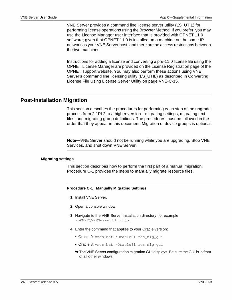
VNE Server User Guide App C—Supplemental Information
VNE Server provides a command line license server utility (LS_UTIL) for performing license operations using the Browser Method. If you prefer, you may use the License Manager user interface that is provided with OPNET 11.0 software; given that OPNET 11.0 is installed on a machine on the same IP network as your VNE Server host, and there are no access restrictions between the two machines.
Instructions for adding a license and converting a pre-11.0 license file using the OPNET License Manager are provided on the License Registration page of the OPNET support website. You may also perform these actions using VNE Server’s command line licensing utility (LS_UTIL) as described in Converting License File Using License Server Utility on page VNE-C-15.
Post-Installation Migration
This section describes the procedures for performing each step of the upgrade process from 2.1PL2 to a higher version—migrating settings, migrating text files, and migrating group definitions. The procedures must be followed in the order that they appear in this document. Migration of device groups is optional.
Note—VNE Server should not be running while you are upgrading. Stop VNE Services, and shut down VNE Server.
Migrating settings
This section describes how to perform the first part of a manual migration. Procedure C-1 provides the steps to manually migrate resource files.
Procedure C-1 Manually Migrating Settings
1 Install VNE Server.
2 Open a console window.
3 Navigate to the VNE Server installation directory, for example \OPNET\VNEServer\3.5.1_x.
4 Enter the command that applies to your Oracle version:
• Oracle 9: vnes.bat /Oracle9i res_mig_gui
• Oracle 8: vnes.bat /Oracle8i res_mig_gui
➥ The VNE Server configuration migration GUI displays. Be sure the GUI is in front of all other windows.
VNE Server/Release 3.5 VNE-C-3
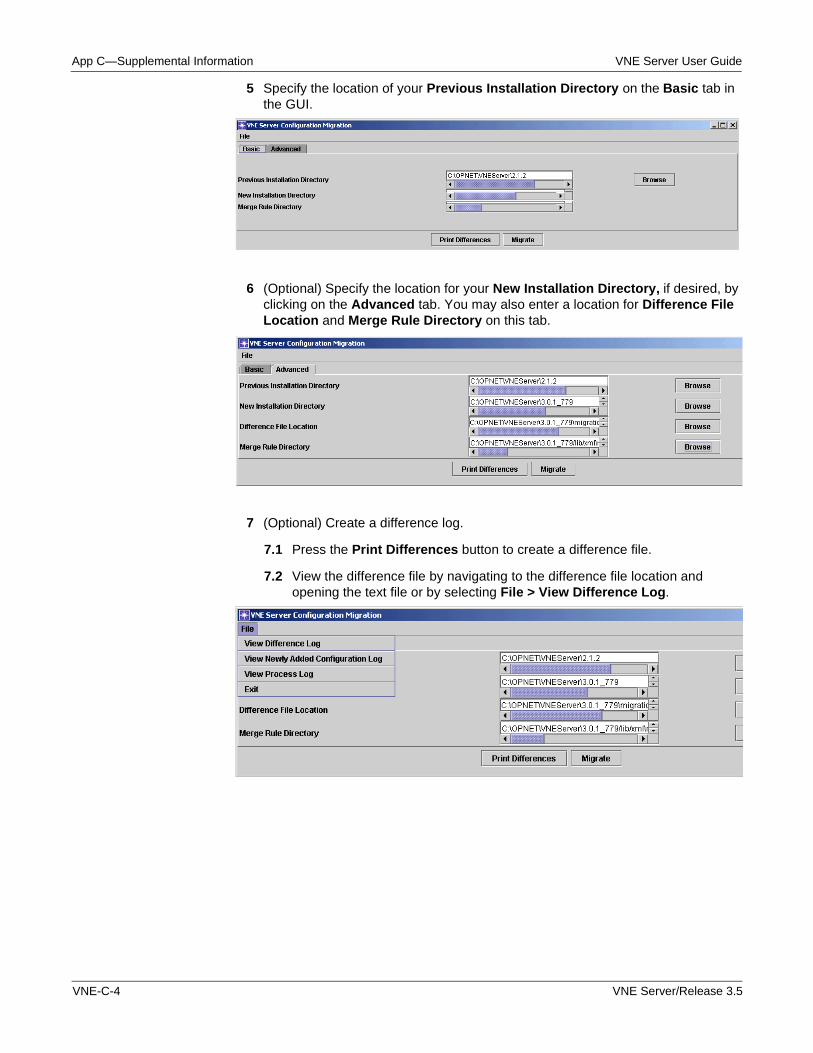
App C—Supplemental Information VNE Server User Guide
5 Specify the location of your Previous Installation Directory on the Basic tab in the GUI.
6 (Optional) Specify the location for your New Installation Directory, if desired, by clicking on the Advanced tab. You may also enter a location for Difference File Location and Merge Rule Directory on this tab.
7 (Optional) Create a difference log.
7.1 Press the Print Differences button to create a difference file.
7.2 View the difference file by navigating to the difference file location and opening the text file or by selecting File > View Difference Log.
VNE-C-4 VNE Server/Release 3.5
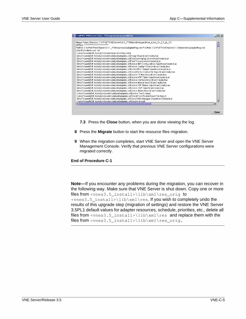
VNE Server User Guide App C—Supplemental Information
7.3 Press the Close button, when you are done viewing the log.
8 Press the Migrate button to start the resource files migration.
9 When the migration completes, start VNE Server and open the VNE Server Management Console. Verify that previous VNE Server configurations were migrated correctly.
End of Procedure C-1
Note—If you encounter any problems during the migration, you can recover in the following way. Make sure that VNE Server is shut down. Copy one or more files from <vnes3.5_install>\lib\xml\res_orig to <vnes3.5_install>\lib\xml\res. If you wish to completely undo the results of this upgrade step (migration of settings) and restore the VNE Server 3.5PL1 default values for adapter resources, schedule, priorities, etc., delete all files from <vnes3.5_install>\lib\xml\res and replace them with the files from <vnes3.5_install>\lib\xml\res_orig.
VNE Server/Release 3.5 VNE-C-5
App C—Supplemental Information VNE Server User Guide
Migrating Text Files
This section describes how to perform the second step of the upgrade process. Procedure C-2 provides the steps to manually migrate user-created files.
Note—During the migration process, old files are renamed from filename to filename_orig. If there is any problem during migration, you can recover by changing the filenames back to their original names.
Note—The following procedure assumes that you have completed Procedure C-1.
Procedure C-2 Manual Migration of User-Created Files
1 Navigate to the VNE Server installation directory.
2 Enter the command that applies to your Oracle version:
• Oracle 9: vnes.bat /Oracle9i file_mig <old_install_dir> <new_install_dir>
• Oracle 8: vnes.bat /Oracle8i file_mig <old_install_dir> <new_install_dir>
3 Open VNE Server to verify the results.
End of Procedure C-2
During the migration, a log file is created in <new_install_dir>\migration\oldVersion. After migration you can examine this file. The log file details what was executed during the file migration.
Migrating Groups (Optional)
If you have groups defined in a 2.1PL2 VNE Server project that you wish to migrate forward, read this section.
VNE-C-6 VNE Server/Release 3.5
VNE Server User Guide App C—Supplemental Information
Procedure C-3 describes the steps to manually migrate device groups.
WARNING—If you wish to migrate groups from a 2.1PL2 installation, you must export the groups from the 2.1PL2 database before you configure the Oracle database for 3.5PL1. When you run the setup accounts script (@setup_accounts.sql), all projects are removed from the Oracle database and you will no longer be able to export group data.
Note—This procedure assumes that you have completed Procedure C-2.
Procedure C-3 Manually Migrating Device Groups
1 Navigate to the VNE Server 3.5PL1 installation directory.
2 Enter the command that applies to your Oracle version:
• Oracle 9: vnes.bat /Oracle9i grp_mig <old_install_dir> <new_install_dir> dbUser dbPwd
• Oracle 8: vnes.bat /Oracle8i grp_mig <old_install_dir> <new_install_dir> dbUser dbPwd
where dbUser and dbPwd are the VNE Server username and password.
3 Check the log file in <vnes3.5_install>\migration\oldVer\Groups to verify that device group migration executed. If no device groups exist in the 2.1PL2 database, no group migration is performed.
Note—When device group migration is complete, perform the following steps:
4 Run the collection and import adapters necessary to build network topology.
5 Import your device groups.
5.1 Open the VNE Server Management Console to verify that the “inputFile” of groupCreate and addNodeToGroup categories in the ASCII Generic Data Import adapter was updated to point to the migrated device group files.
5.2 Set the two data categories to active, and run the ASCII Generic Data Import adapter.
5.3 Run the ASCII Generic Data Import adapter.
End of Procedure C-3
WARNING—Device group migration does not handle sub-groups. If any device groups contain other groups, the sub-groups will not be in the ASCII group files created. You must manually recreate the sub-groups using the Group Configuration tool or ASCII data files.
VNE Server/Release 3.5 VNE-C-7
App C—Supplemental Information VNE Server User Guide
If you migrated device groups from the previous installation, and you wish to delete them, perform this procedure.
Procedure C-4 Delete Imported Device Groups
1 From the Control Panel, select Configuration > Open Group Configuration.
➥ The VNE Group Configuration browser opens.
2 Click on the root node in the left navigation panel of the Group Browser.
➥ A list of groups defined for your project appears in the right panel.
3 Select a group that you wish to delete. Right-click and select Delete from the menu to delete the group. Repeat for each group you wish to delete.
End of Procedure C-4
Oracle Performance Enhancements
The setup accounts script (@setup_accounts.sql) that you use to configure the database following installation of VNE Server 3.5 has been enhanced to analyze Oracle 9i memory-related database parameters and recommend changes, when applicable, to improve VNE Server performance. The parameters that are examined are the Oracle SGA_MAX SIZE and DB_CACHE_SIZE parameters. After the setup accounts script completes, a recommendation may be made to run a database parameters change script (@dbparamchg.sql) to modify these parameters.
Note—Consult with your Oracle database administrator before making changes to the Oracle database.
Note—Ensure that there is at least 500 MB of physical memory available on the Oracle server host before making these changes.
If you choose to run the database parameters change script, the changes will apply to the database instance into which you are logged in when you run the setup accounts script.The database parameters change script increases the SGA_MAX SIZE from ~130 MB to ~560 MB and the DB_CACHE_SIZE from ~25 MB to ~85 MB. These changes increase the amount of memory used by Oracle and improve data import performance for large networks. The most significant performance changes are noted for import of data on very large networks (greater than 100,000 interfaces).
VNE-C-8 VNE Server/Release 3.5
VNE Server User Guide App C—Supplemental Information
Refer to the sections on Configuring the Oracle Database and Modifying Database Parameters in the VNE Server 3.5 Windows Installation card for additional information and instructions.
Archiving Configuration Data
VNE Server 3.5 provides the ability to store configuration data. The term "configuration data" is used generically to refer to show command output collected from a device via command line interface (CLI) and stored in a text file. As an example, the configuration data for a Cisco router may include configuration, version, CDP, and interface files containing the output of the ‘show running-config’, ‘show version’, ‘show cdp neighbors detail’, and ‘show interfaces’ commands, respectively. Since VNE Server now stores the source configuration data, it can be provided to other OPNET software.
VNE Server retains only the most recent configuration data. When new data is available for a device, it overwrites the data in the archive.
VNE Server adapters that collect configuration data are
• CiscoWorks Config File Collection
• Device Config File Collection
• Remote File Collection.
When the Device Config File Collection adapter runs, the configuration data is temporarily stored in the <vnes_tmp>\Collect\<data_type>\<process_num> directory. When collection is complete, the collected configuration data is copied to the archive, the <process_num> directory and files are appended with .ARCHIVED. When Device Config File Import runs, data is imported from the archive (not the Collect directory), and an association is made between the node in the VNE Server database and the archived configuration data. This relationship is stored in the NODE.CFA configuration. If VNE Server services are stopped before Device Config File Collection completes, the collection is terminated. Subsequent attempts to import the collected data using Device Config File Import adapter fails, because the collected data was not archived. If you wish to import the files from the partial collection, copy them to <vnes_temp>\Input\<config_data_type> and run the appropriate import adapter. For example, if you wish to import a partial collection of configuration files, copy the files to op_admin\tmp\vne\Input\Configs and run the Device Config File Import adapter.
VNE Server/Release 3.5 VNE-C-9
App C—Supplemental Information VNE Server User Guide
The configuration data available from the CiscoWorks Config File Collection adapter is limited to configuration files only. For CiscoWorks Config File Collection, the files are temporarily stored in <vnes_tmp>\Collect\Configs_CiscoWorks directory. When the CiscoWorks Config File Import adapter runs, the collected configuration files are copied to the archive, and the files are appended with .ARCHIVED. The configuration files are then imported from the archive and the NODE.CFA configuration is created or updated.
Note—Files and folders that have been appended with .ARCHIVED are removed when you run the maintenance adapter. In previous versions of VNE Server, as Device Config File Collection adapter collected data it overwrote files collected previously. Now each time the Device Config File Collection adapter runs, files are written to a separate subdirectory. Remember to run the maintenance adapter on a regular basis to clean up disk space.
If you run the Remote File Collection adapter to copy configuration data to the VNE Server host, we recommend that you copy the data to <vnes_temp>\Input\<config_data_type> directory, and then run the appropriate import adapter for that data type. The workflow for Remote File Collection and import is similar to the CiscoWorks archiving workflow.
CiscoWorks Config File Import and other import adapters may add entries to the Device Info file as part of the archiving process. You may need to press Reload from File in the Device and Platform Info tab to see the entries. The Device Info file entries added during import are created with the global Active property enabled, but no data is provided except Device Name and SysName.
Collected configuration data can accumulate if multiple collections have been completed without the associated import adapter being run. If you run collection adapters, such as Device Config File Collection, run the associated import adapter, such as Device Config File Import, or manually delete files that are not archived.
WARNING—Do not rename the archive directory. Do not delete files from the archive directory. You may clear the archive in the following way. Stop VNE Server Services. Select Remove archives dir and records from current project from the Control Panel Tools menu. The archive directory will be deleted and the NODE.CFA configurations removed from the database.
VNE-C-10 VNE Server/Release 3.5
VNE Server User Guide App C—Supplemental Information
Tracking Changes in VNE Server
VNE Server has properties that enable tracking of changes in the network database.
• persistChanges—enables tracking of detected network changes. When persistChanges is enabled, you can use the incremental import mode when importing from VNE Server into OPNET.
• persistArchiveChanges—complements persistChanges by recording the source adapter responsible for the change. When both persistChanges and persistArchiveChanges are enabled, detailed change reporting is provided and VNE Server's change reports are populated.
Note—When persistChanges is disabled, this property has no effect.
WARNING—These attributes should be enabled after building the initial network database baseline. This will prevent VNE Server from recording changes for the entire new network database as it is created. If you migrate resources from 2.1PL2 to a higher version, check the state of these attributes in 3.5 before you begin initial import. Make sure both are set to false.
When you enable change tracking, make sure that you add the Change Records Maintenance Service to your schedule and run it on a regular basis. The Change Records Maintenance Service manages database growth that results when network change history is saved in the database.
Incremental Import
Before you enable change tracking in VNE Server, first build a baseline network topology by collecting and importing data into the VNE Server database. Import this baseline into OPNET. Next, enable change tracking in VNE Server. To enable change tracking, open the VNE Server Management Console. Expand Project Properties > VNESfeatures. Enable the “persistChanges” attribute by setting it to true. Stop and restart VNE Server services to apply this change. Run your selected collection and import adapters as usual. The next time you import from VNE Server into OPNET, you can employ the incremental import mode.
System Change Reporting
To use system change reporting, first build a baseline network topology by collecting and importing data into the VNE Server database. Next enable system change reporting. To enable system change reporting, open the VNE Server Management Console. In Project Properties tab, expand VNESfeatures, and enable both the persistChanges and persistArchiveChanges attributes by setting them to true. Stop and restart VNE Server services to apply this change, then run your selected collection and import adapters as usual. Changes from the baseline can be examined using the System Change reports.
VNE Server/Release 3.5 VNE-C-11
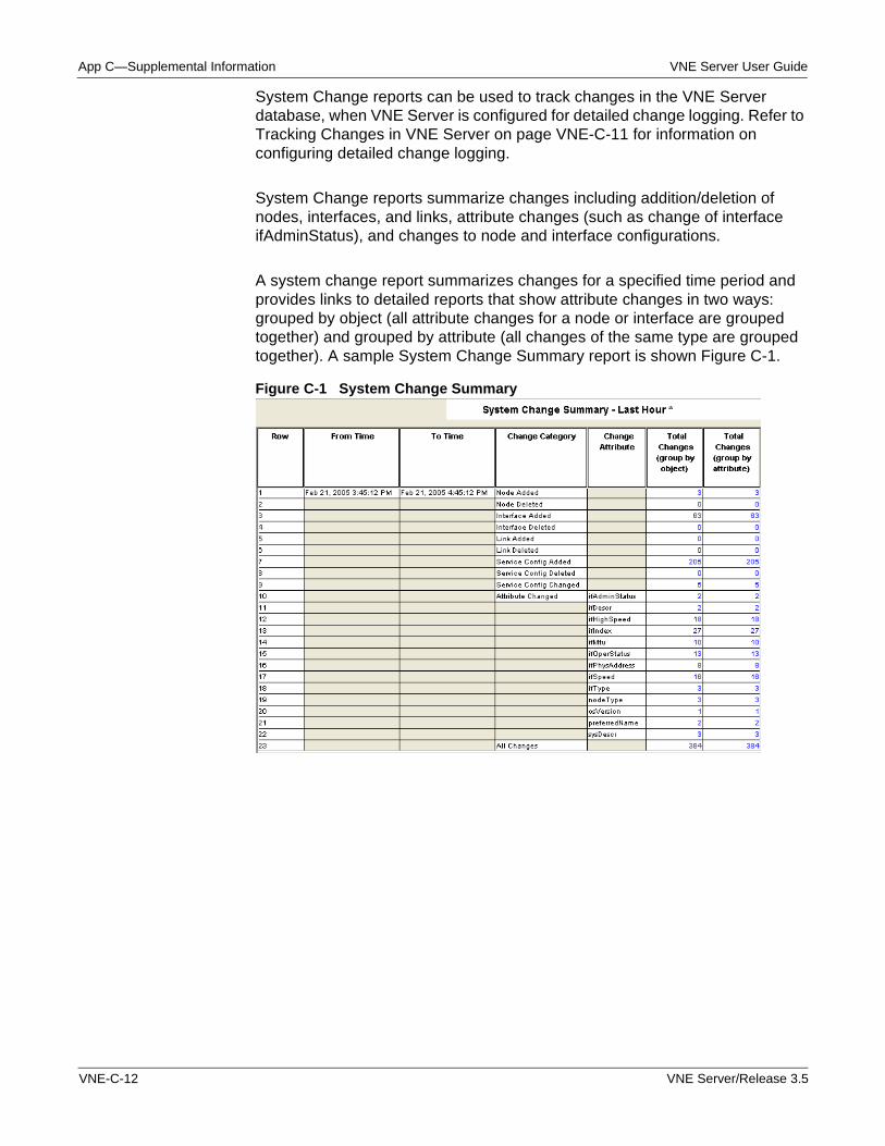
App C—Supplemental Information VNE Server User Guide
System Change reports can be used to track changes in the VNE Server database, when VNE Server is configured for detailed change logging. Refer to Tracking Changes in VNE Server on page VNE-C-11 for information on configuring detailed change logging.
System Change reports summarize changes including addition/deletion of nodes, interfaces, and links, attribute changes (such as change of interface ifAdminStatus), and changes to node and interface configurations.
A system change report summarizes changes for a specified time period and provides links to detailed reports that show attribute changes in two ways: grouped by object (all attribute changes for a node or interface are grouped together) and grouped by attribute (all changes of the same type are grouped together). A sample System Change Summary report is shown Figure C-1.
Figure C-1 System Change Summary
VNE-C-12 VNE Server/Release 3.5
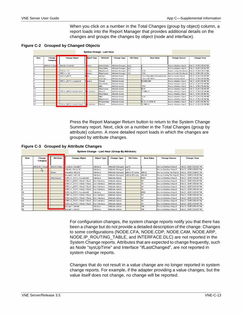
VNE Server User Guide App C—Supplemental Information
When you click on a number in the Total Changes (group by object) column, a report loads into the Report Manager that provides additional details on the changes and groups the changes by object (node and interface).
Figure C-2 Grouped by Changed Objects
Press the Report Manager Return button to return to the System Change Summary report. Next, click on a number in the Total Changes (group by attribute) column. A more detailed report loads in which the changes are grouped by attribute changes.
Figure C-3 Grouped by Attribute Changes
For configuration changes, the system change reports notify you that there has been a change but do not provide a detailed description of the change. Changes to some configurations (NODE.CFA, NODE.CDP, NODE.CAM, NODE.ARP, NODE.IP_ROUTING_TABLE, and INTERFACE.DLC) are not reported in the System Change reports. Attributes that are expected to change frequently, such as Node "sysUpTime" and Interface "ifLastChanged", are not reported in system change reports.
Changes that do not result in a value change are no longer reported in system change reports. For example, if the adapter providing a value changes, but the value itself does not change, no change will be reported.
VNE Server/Release 3.5 VNE-C-13
App C—Supplemental Information VNE Server User Guide
Licensing
VNE Server has the following restrictions and limitations with respect to product licensing.
• VNE Server requires an OPNET 11.0 license server and a license file in the 11.0 format.
• Standalone licensing is not supported by VNE Server.
• Loanable licenses are not supported by VNE Server.
• Only one local license server may be installed on the VNE Server host.
• The OPNET licensing software deployed with VNE Server does not include the License Manager user interface. Instead, a command line utility, LS_UTIL, is provided.
• VNE Server’s command line licensing utility (LS_UTIL) cannot revoke a license managed by a remote license server.
VNE-C-14 VNE Server/Release 3.5
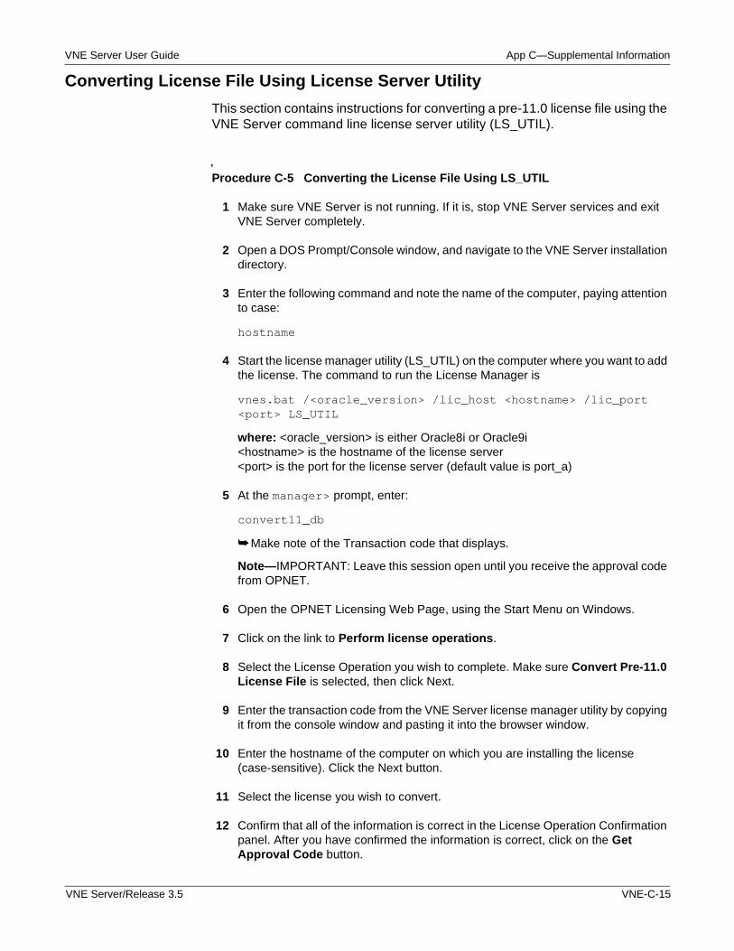
VNE Server User Guide App C—Supplemental Information
Converting License File Using License Server Utility
This section contains instructions for converting a pre-11.0 license file using the VNE Server command line license server utility (LS_UTIL).
Procedure C-5 Converting the License File Using LS_UTIL
1 Make sure VNE Server is not running. If it is, stop VNE Server services and exit VNE Server completely.
2 Open a DOS Prompt/Console window, and navigate to the VNE Server installation directory.
3 Enter the following command and note the name of the computer, paying attention to case:
hostname
4 Start the license manager utility (LS_UTIL) on the computer where you want to add the license. The command to run the License Manager is
vnes.bat /<oracle_version> /lic_host <hostname> /lic_port <port> LS_UTIL
where: <oracle_version> is either Oracle8i or Oracle9i<hostname> is the hostname of the license server<port> is the port for the license server (default value is port_a)
5 At the manager> prompt, enter:
convert11_db
➥ Make note of the Transaction code that displays.
Note—IMPORTANT: Leave this session open until you receive the approval code from OPNET.
6 Open the OPNET Licensing Web Page, using the Start Menu on Windows.
7 Click on the link to Perform license operations.
8 Select the License Operation you wish to complete. Make sure Convert Pre-11.0 License File is selected, then click Next.
9 Enter the transaction code from the VNE Server license manager utility by copying it from the console window and pasting it into the browser window.
10 Enter the hostname of the computer on which you are installing the license (case-sensitive). Click the Next button.
11 Select the license you wish to convert.
12 Confirm that all of the information is correct in the License Operation Confirmation panel. After you have confirmed the information is correct, click on the Get Approval Code button.
VNE Server/Release 3.5 VNE-C-15
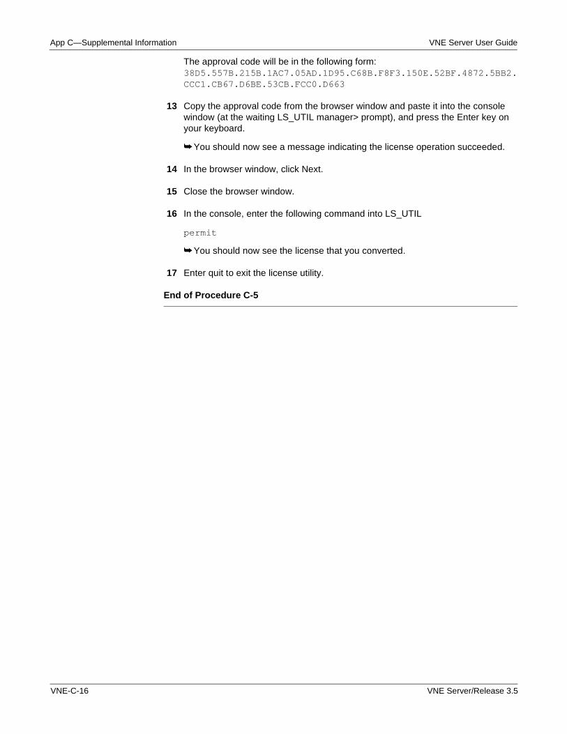
App C—Supplemental Information VNE Server User Guide
The approval code will be in the following form: 38D5.557B.215B.1AC7.05AD.1D95.C68B.F8F3.150E.52BF.4872.5BB2.CCC1.CB67.D6BE.53CB.FCC0.D663
13 Copy the approval code from the browser window and paste it into the console window (at the waiting LS_UTIL manager> prompt), and press the Enter key on your keyboard.
➥ You should now see a message indicating the license operation succeeded.
14 In the browser window, click Next.
15 Close the browser window.
16 In the console, enter the following command into LS_UTIL
permit
➥ You should now see the license that you converted.
17 Enter quit to exit the license utility.
End of Procedure C-5
VNE-C-16 VNE Server/Release 3.5
VNE Server User Guide Index
Index
A Account Management, VNE-5-25 Adapter Priority, VNE-2-51 Adapter Resources, VNE-2-53 Adapter Schedule, VNE-2-49 Adapter Status Panel, VNE-2-22 Adapters and Services, VNE-1-5, VNE-3-1 Adapters Do Not Run as Intended, VNE-A-25 Administration, VNE-5-1 Altering the Appearance of a Report, VNE-2-62 Architecture, VNE-1-3 Archiving Configuration Data, VNE-C-9 ASCII Generic Data Import, VNE-3-59
B Backup and Recovery, VNE-5-35
C Cannot Communicate with the Target Network, VNE-A-22 Cannot Import a VNE Server Network Model into the OPNET
analysis software, VNE-A-31 Cannot Obtain a License When Starting VNE Server,
VNE-A-33 Cannot Run the Oracle Installer, VNE-A-17 Cannot Start VNE Server, VNE-A-17 Cannot Start VNE Server Services, VNE-A-18 Cflowd Import, VNE-3-59 Chaining Adapters, VNE-4-11 Change Records Maintenance Service, VNE-3-64 Changing Adapter Login and Show Command Properties,
VNE-3-11 Choosing a Project Name, VNE-5-5 Choosing Adapters, VNE-4-7 Cisco Netflow Import, VNE-3-57 Cisco PIX Firewall Commands, VNE-B-2 Cisco WAN Manager Import, VNE-3-29 CiscoWorks Adapters, VNE-3-26, VNE-4-7 CiscoWorks ANI Database Import, VNE-3-28 CiscoWorks Config File Collection, VNE-3-24 CiscoWorks Config File Import, VNE-3-26 CiscoWorks on a UNIX Host, VNE-5-39 CiscoWorks on a Windows Host, VNE-5-38 CiscoWorks RME Database Import, VNE-3-27 Collecting a CiscoWorks Inventory File, VNE-5-40 Collecting CiscoWorks Server Information, VNE-5-39 Collecting Utilization Data, VNE-4-8 Command Line Utilities, VNE-5-16 Common Operations, VNE-A-13 Comparing Reports, VNE-2-62 Concord eHealth Network Utilization Import, VNE-3-44 Configuration, VNE-4-3
Configuration Files are Not Collected for a Specific Device, VNE-A-26
Configuration Files are Not Collected or Imported, VNE-A-25 Configuration Menu, VNE-2-9 Configuration Problems, VNE-A-22 Configuring Adapters, VNE-4-9 Configuring CiscoWorks, VNE-5-38 Configuring Concord eHealth, VNE-5-41 Configuring Device Login Properties, VNE-3-8 Configuring HP OpenView, VNE-5-37 Configuring InfoVista, VNE-5-42 Configuring MRTG, VNE-5-41 Configuring OPNET analysis software to Import from VNE
Server, VNE-5-22 Configuring Show Command Properties, VNE-3-9 Configuring VNE Server, VNE-4-5 Console, VNE-2-5, VNE-2-19 Console Detail View, VNE-2-19 Console File Menu, VNE-2-25 Console Logs Menu, VNE-2-27 Console Summary View, VNE-2-19 Console View Menu, VNE-2-25, VNE-2-27 Continuous Operation, VNE-4-3, VNE-4-14 Control Panel, VNE-2-5 Converting License File Using License Server Utility,
VNE-C-15 Converting the License File Using LS_UTIL, VNE-C-15 Create a Device Info File Offline, VNE-2-44, VNE-4-5 Create a Device Info File Online, VNE-4-6 Creating Device Access Information, VNE-4-5
D Data Menu, VNE-2-14 Database Aging Service, VNE-3-62 Delete Imported Device Groups, VNE-C-8 Deleting All Projects and Tables, VNE-2-4 Deleting the Current Project, VNE-2-4 Deleting the Temporary Directory and Current Project,
VNE-2-5 Delimiter, VNE-C-1 Demand Traffic Processing Service, VNE-3-59 Demand Traffic Rollup Service, VNE-3-76 Deployment Scenarios, VNE-5-12 Detail View, VNE-2-19 Determining the Oracle Database Used by VNE Server,
VNE-A-15 Determining the Oracle Net Service Names Known to the VNE
Server Host, VNE-A-15 Device and Platform Info, VNE-2-41 Device ARP Table Import, VNE-3-20 Device Asset Information is Not Collected for a Device,
VNE-A-29
VNE Server/Release 3.5 VNE-IX-1
E VNE Server User Guide
Device CAM Table Import, VNE-3-21 Device CDP Import, VNE-3-20 Device Config File Collection, VNE-3-1 Device Config File Import, VNE-3-16 Device Configuration Commands, VNE-B-1 Device Configuration Import Adapters, VNE-3-15 Device FR Map Import, VNE-3-19 Device ifIndex Import, VNE-3-19 Device Info File, VNE-2-41 Device Interface Import, VNE-3-20 Device IP Route Import, VNE-3-20 Device MIB Configuration Import, VNE-3-33 Device Module Import, VNE-3-21 Device Version Import, VNE-3-20 Device VLAN Database Import, VNE-3-21 Device VTP Status Import, VNE-3-21 DNS Alias Import, VNE-3-37 Documentation Roadmap, VNE-1-8
E Evaluating the Network Model, VNE-4-9 Event Information, VNE-2-29 Event Selection and Navigation, VNE-2-29 Event Viewer, VNE-2-27 Event Viewer File Menu, VNE-2-32 Event Viewer View Menu, VNE-2-33 Export Service, VNE-3-77 Exporting Reports to Files, VNE-5-9 External Adapter, VNE-3-73 Extreme Commands, VNE-B-21 Extreme commands, VNE-B-21
F Failure to Connect to the CiscoWorks ANI Database,
VNE-A-30 Failure to Connect to the CiscoWorks RME Database,
VNE-A-29 Fields, VNE-C-1 File Menu, VNE-2-7, VNE-2-32 Filing an OPNET Technical Support Case, VNE-A-34 Font Properties, VNE-2-53 Format of the Device Info File, VNE-C-1 Foundry Commands, VNE-B-25
G Group Browser, VNE-2-9 Grouped by Attribute Changes, VNE-C-13 Grouped by Changed Objects, VNE-C-13
H Header, VNE-2-44, VNE-C-1 Help Menu, VNE-2-18 HP OpenView NNM Import, VNE-3-36
I Important Files, VNE-5-2, VNE-5-22 Incremental Import, VNE-C-11 InfoVista Network Utilization Import, VNE-3-51 Installation, VNE-4-2 Installation Problems, VNE-A-15 Interface Utilization Rollup Service, VNE-3-71 Introduction, VNE-1-1, VNE-2-1, VNE-3-1, VNE-4-1,
VNE-5-1, VNE-A-1
L License Administration, VNE-5-13 License Procedures, VNE-5-17 License Resources, VNE-5-15 Licensing, VNE-C-14 Licensing Changes, VNE-C-2 Licensing Operations, VNE-5-17 Licensing Problems, VNE-A-33 Licensing Resources, VNE-5-15 Link and Connection Inference Service, VNE-3-37 Locating Oracle Release Information, VNE-A-14 Locating VNE Server Release Information, VNE-A-14 Logs Menu, VNE-2-15, VNE-2-33
M Maintenance Service, VNE-3-62 Management Console, VNE-2-34 Managing Log File Growth, VNE-5-7 Managing Logs and Traffic Data, VNE-5-7 Managing Projects, VNE-5-5 Managing Traffic Data Growth, VNE-5-8 Manual Migration of User-Created Files, VNE-C-6 Manually Migrating Device Groups, VNE-C-7 Manually Migrating Settings, VNE-C-3 Merge Rules, VNE-2-53 MIB Data is Not Collected for a Specific Device, VNE-A-26 MIB-Based Interface Utilization Import, VNE-3-43 MIB-Based Interface Utilization Import Adapter, VNE-4-11 Migrating Groups (Optional), VNE-C-6 Migrating settings, VNE-C-3 Migrating Text Files, VNE-C-6 Monitoring Data Collection, VNE-4-15 Monitoring the Database, VNE-5-27 MRTG Interface Utilization Import, VNE-3-47
N NetScout nGenius Import, VNE-3-58 Network Browser, VNE-2-67 Network Management System Administration, VNE-5-37 No Network Data is Written to the Oracle Database,
VNE-A-23 Nortel BGP/EGP, VNE-B-10 Nortel EPIC Output Import, VNE-3-21 Nortel Global Commands, VNE-B-7
VNE-IX-2 VNE Server/Release 3.5
VNE Server User Guide O
Nortel Interface Commands, VNE-B-7 Nortel Networks Commands, VNE-B-7 Nortel Networks Passport 7480, 15000, 20000 Commands,
VNE-B-19 Nortel Networks Passport 7480, 15000, 20000 commands,
VNE-B-19 Nortel Networks Passport 8000 Commands, VNE-B-14 Nortel Networks Passport 8000 commands, VNE-B-14 Nortel OSPF Commands, VNE-B-9 Nortel RIP Commands, VNE-B-8
O Opening the OPNET Licensing Web Page, VNE-2-3 Opening the VNE Server Control Panel, VNE-2-6 Operation, VNE-4-1 Operation Problems, VNE-A-27 Oracle Administration, VNE-5-22 Oracle Net Services, VNE-5-23 Oracle ORA-4031 Shared Pool Memory Allocation Errors,
VNE-A-27 Oracle Performance Enhancements, VNE-C-8 Overview, VNE-1-1
P Performing License Operations, VNE-2-5 Post Processor Service, VNE-3-59 Post-Installation Migration, VNE-C-3 Preferences, VNE-2-73 Printing and Exporting a Report, VNE-2-62 Problem Scenarios, VNE-A-15 Product Licensing, VNE-5-12 Project Properties, VNE-2-37
R Reconfiguring VNE Server Data Collection, VNE-5-6 Remote File Collection, VNE-3-21 Removing and Recreating VNE Server User Account and
Database from Oracle, VNE-A-28 Removing VNE Server Database Accounts within Oracle,
VNE-5-26 Report Export Service, VNE-3-64 Report Manager, VNE-2-54 Report Manager File Menu, VNE-2-65 Report Manager Options Menu, VNE-2-66 Report Summary, VNE-2-54 Restrictions and Limitations, VNE-5-15
S Scheduling Adapters, VNE-4-10 Searching a Report, VNE-2-62 Selecting Reports, VNE-2-60 Services Halt and Database Error Events Appear in the Event
Viewer, VNE-A-28 Services Menu, VNE-2-8 Services Shut Down Due to License Problems, VNE-A-33
Setting Up VNE Server Database Accounts within Oracle, VNE-5-25
Software Upgrades, VNE-5-10 Starting Data Collection, VNE-4-14 Starting Data Collection for the First Time, VNE-4-14 Starting the Report Manager, VNE-2-60 Starting VNE Server, VNE-2-2, VNE-2-4, VNE-4-4 StatScout Interface Utilization Import, VNE-3-47 Status Display Filter, VNE-2-24 Summary View, VNE-2-19 Supplemental Information, VNE-C-1 System Change Reporting, VNE-C-11 System Change Summary, VNE-C-12 System Status Panel, VNE-2-21
T Temporary Directory, VNE-5-3 Testing Adapters, VNE-3-78 The Oracle Database Does Not Restart Correctly After PC
startup, VNE-A-23 The VNE Server Program Group, VNE-2-2 Tools Menu, VNE-2-18 Trace Route Link Inference Service, VNE-3-41 Tracking Changes in VNE Server, VNE-C-11 Troubleshooting, VNE-A-1
U Unexpected Devices are Present in the Network Database,
VNE-A-29 User Interface, VNE-2-1 User Interface Elements, VNE-2-34 User Interfaces, VNE-1-4 Using the Console to Monitor VNE Server, VNE-2-34 Using the Network Browser, VNE-4-20 Using the Report Manager, VNE-4-16 Using the VNE Server Console to Start and Monitor Data
Collection, VNE-4-14
V Verifying the Oracle Configuration, VNE-5-26 View Menu, VNE-2-33 Viewing a Report, VNE-2-61 Viewing Element History, VNE-2-63 Viewing Event Log Files, VNE-2-3, VNE-2-5 Viewing VNE Server Documentation, VNE-2-3, VNE-2-5 VNE Server Administration, VNE-5-1 VNE Server Cannot Connect to the Database, VNE-A-20 VNE Server Installation Fails, VNE-A-16 VNE Server Workflow, VNE-4-2 vne_import_dbox_start_function preference, VNE-2-73 vne_import_ior_file preference, VNE-2-73 vne_import_post_operation_function preference, VNE-2-73 vne_import_post_operation_library preference, VNE-2-73 vne_import_postproc_function preference, VNE-2-74 vne_import_process_library preference, VNE-2-74
VNE Server/Release 3.5 VNE-IX-3
V VNE Server User Guide
vne_import_ssm_directory preference, VNE-2-74 vne_import_state_destroy_function preference, VNE-2-74
vne_import_state_library preference, VNE-2-74 vne_import_state_register_function preference, VNE-2-75
VNE-IX-4 VNE Server/Release 3.5