Embed Size (px)
Citation preview
15th International Conference on Composite Materials (ICCM-15), Durban, South Africa, 27 June to 01 July 2005
VOID EVOLUTION DURING STAMP-FORMING OF THERMOPLASTIC COMPOSITES
M.D. Wakeman1, P. Blanchard2, J.-A. E. Månson1*
1Ecole Polytechnique Fédérale de Lausanne (EPFL), Laboratoire de Technologie des Composites et Polymères (LTC),
CH-1015 Lausanne, Switzerland Email: [email protected] , [email protected]
2Ford Motor Company, Ford Research Lab,
2101 Village Road, Mail Drop 3135, Dearborn, MI 48121, USA Email: [email protected]
SUMMARY: A thermoplastic stamp-forming process has been investigated using glass fibre (GF), carbon fibre (CF), and hybrid carbon-glass fibre fabric materials. For monolithic GF/PA6 and CF/PA66 materials, stamping pressure was the dominating variable to achieve high mechanical properties, low void contents, and minimal void content distributions across the stamped part. Use of a hybrid flow core material composed of CF/PA66 textile skins and a GF/PA66 random fibre core reduced this tendency such that tool temperature dominated the process. The increased local flow of the core layer accommodated the varying local superficial fabric density. Use of the flow core did not significantly affect flexural properties, but with a 29% and 17% drop in tensile modulus and strength. A substantial cost saving resulted from the use of a hybrid glass and carbon structure. In mould cycle times of 30s resulted for 3mm thick parts. KEYWORDS: thermoplastic, compression, moulding, voids, image analysis, flow, consolidation
INTRODUCTION In response to driving forces requiring weight reduction in automotive structures, a stamp-forming process has been investigated using glass fibre (GF), carbon fibre (CF), and hybrid carbon-glass fibre fabrics impregnated with polyamide (PA). This approach is targeted towards high manufacturing volumes. The objectives were to identify the dominating stamping parameters, to determine limiting cycle times, and establish the interrelation of void content evolution and the arising mechanical properties. As a trimming operation was required after stamp forming of the blank, over-injection moulding of recycled material onto a stamped composite sheet has previously been studied as a means of recycling scrap material and a method to increase the functionality of structural thermoplastic composite materials [1].
MATERIALS AND TESTING Materials The study examined the range of commercially available textile thermoplastic composite materials including GF based, CF based, sandwich structures of textile skins and flowable random fibre architecture core layers (denoted flowcore, FC), and hybrid CF and GF based sheet material. All grades were preconsolidated. Study of CF/PA12 materials has been reported previously [1]. Table 1 summarizes the grades reported in this paper. This hence represented the range from lower cost commodity glass-fibre polypropylene (PP) materials to monolithic * To whom all correspondence should be addressed
15th International Conference on Composite Materials (ICCM-15), Durban, South Africa, 27 June to 01 July 2005
CF/PA66 sheet. All materials were of nominally 3mm initial thickness. All weaves reported here were of 1/1 orientation unless otherwise stated; 4/1 weaves were also studied.
Table 1: Thermoplastic composite sheet materials investigated Matrix Material code Fibre architecture/impregnation route type Tm
Voids (sheet), (%)
GF/PP GF commingled yarn textile, calendaring 7.3
GMTex GF weave skins, random needled GF core, melt impregnation in DBP 2.5
GMCTex UD CF skins, random needled GF core, , melt impregnation in DBP 6.2
NMTex GF commingled yarn textile skins (2x1mm) + core 50/50 (wt.%) PP/ kenaf/hemp/flax, melt
impregnation in DBP
PP 165
10.7
GF/PA6 GF weave, melt impregnation in DBP 1.7
GF/PA6-FC GF textile skins, 1mm random GF core, melt impregnation in DBP
PA6 220 2.6
CF/PA66 CF weave, melt impregnation in DBP 1.6
CF/PA66-FC CF textile skins, 1mm random GF core, melt impregnation in DBP
PA66 260 1.7
STAMP-FORMING TRIALS
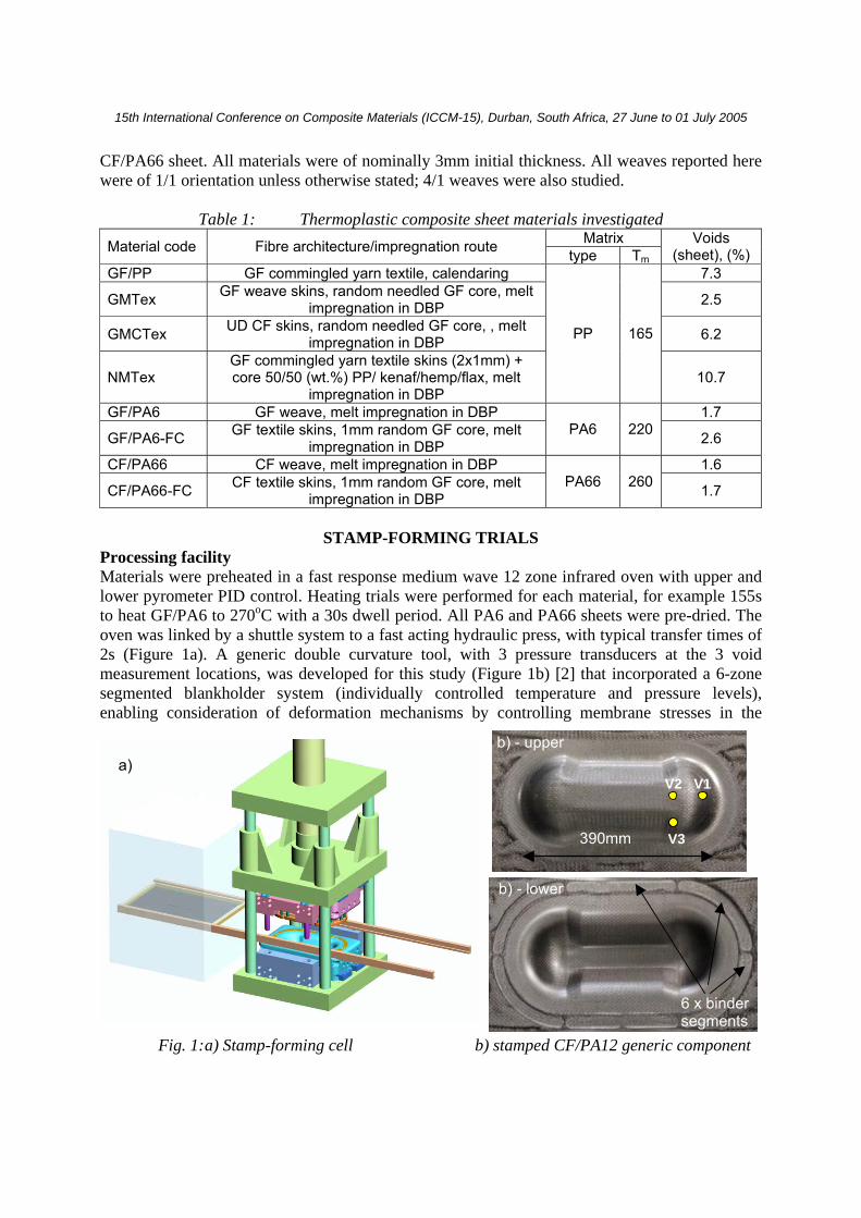
Processing facility Materials were preheated in a fast response medium wave 12 zone infrared oven with upper and lower pyrometer PID control. Heating trials were performed for each material, for example 155s to heat GF/PA6 to 270oC with a 30s dwell period. All PA6 and PA66 sheets were pre-dried. The oven was linked by a shuttle system to a fast acting hydraulic press, with typical transfer times of 2s (Figure 1a). A generic double curvature tool, with 3 pressure transducers at the 3 void measurement locations, was developed for this study (Figure 1b) [2] that incorporated a 6-zone segmented blankholder system (individually controlled temperature and pressure levels), enabling consideration of deformation mechanisms by controlling membrane stresses in the
Fig. 1: a) Stamp-forming cell b) stamped CF/PA12 generic component
a) b) - upper
b) - lower
6 x binder segments
390mm
V1 V2
V3
15th International Conference on Composite Materials (ICCM-15), Durban, South Africa, 27 June to 01 July 2005
material to eliminate wrinkling, and measurement of coupon-based mechanical properties. A binder force of 250N/segment was applied as standard.
CHARACTERISATION
Mechanical tests Mechanical tests were performed on stamped parts with the tensile specimens cut from the top straight section and the 4 flexural samples cut from the flat side panels. Sample dimensions were: tensile; 170mm length, 19mm width with a reduced central width of 12.5mm; flexural, 127mm length, 25.4mm width, rectangular. Void content samples were located as shown above. Void content characterization Void contents were determined by optical microscopy at the three stages of: as delivered, after preheating (deconsolidation), and after stamping. Multiple images were taken using an automated x, y, z stage of an area typically 15mm-20mm width and the full sample thickness to include a statistically representative area of the overall fibre architecture. The grey scale images were automatically combined into a stack (100-200 images) representing the sample area, and the region of interest was defined manually to consider non-linear sample boundaries. A binary threshold was applied to this image to segment the porosity (black) from the reinforcing fibres and matrix material (white). The groupings of black pixels were then classified according to size and distribution using image analysis techniques. This gave sufficient system resolution to resolve voids inside fibre bundles.
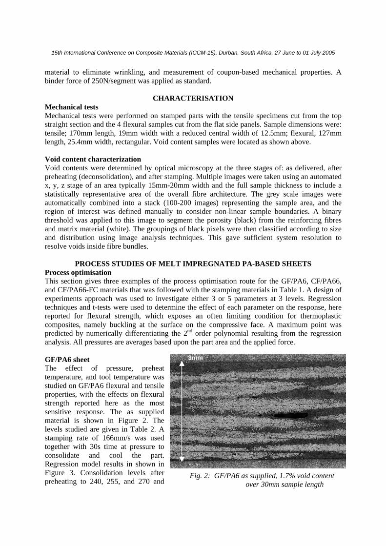
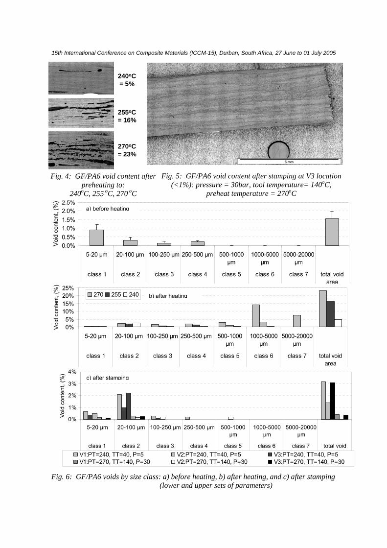
PROCESS STUDIES OF MELT IMPREGNATED PA-BASED SHEETS Process optimisation This section gives three examples of the process optimisation route for the GF/PA6, CF/PA66, and CF/PA66-FC materials that was followed with the stamping materials in Table 1. A design of experiments approach was used to investigate either 3 or 5 parameters at 3 levels. Regression techniques and t-tests were used to determine the effect of each parameter on the response, here reported for flexural strength, which exposes an often limiting condition for thermoplastic composites, namely buckling at the surface on the compressive face. A maximum point was predicted by numerically differentiating the 2nd order polynomial resulting from the regression analysis. All pressures are averages based upon the part area and the applied force. GF/PA6 sheet The effect of pressure, preheat temperature, and tool temperature was studied on GF/PA6 flexural and tensile properties, with the effects on flexural strength reported here as the most sensitive response. The as supplied material is shown in Figure 2. The levels studied are given in Table 2. A stamping rate of 166mm/s was used together with 30s time at pressure to consolidate and cool the part. Regression model results in shown in Figure 3. Consolidation levels after preheating to 240, 255, and 270 and
3mm
Fig. 2: GF/PA6 as supplied, 1.7% void content over 30mm sample length
15th International Conference on Composite Materials (ICCM-15), Durban, South Africa, 27 June to 01 July 2005
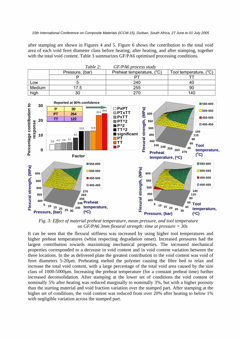
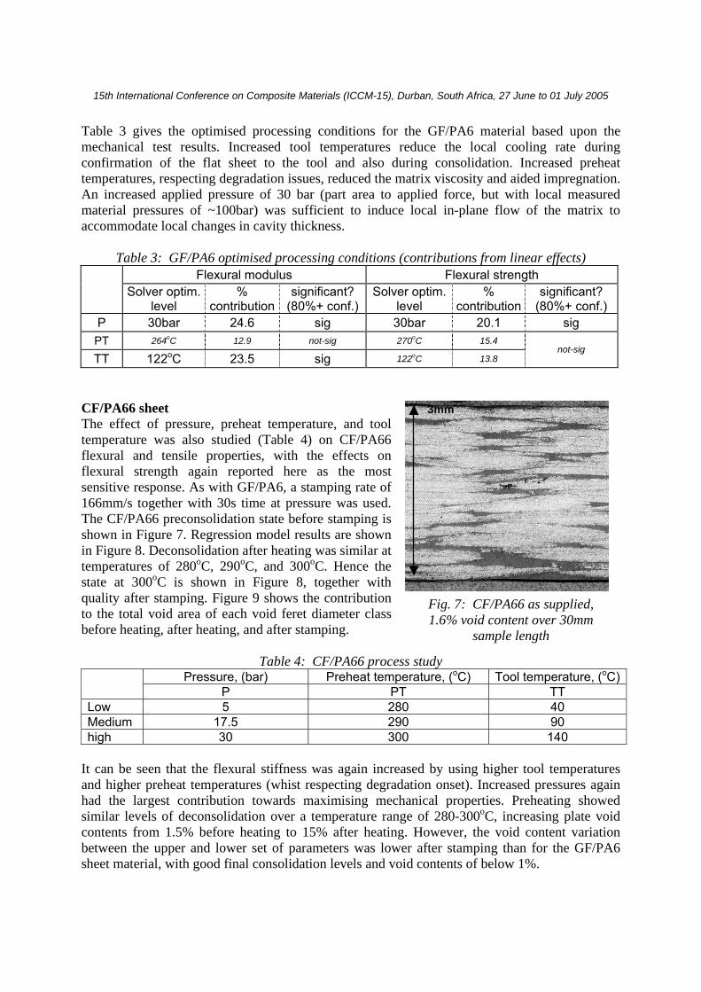
after stamping are shown in Figures 4 and 5. Figure 6 shows the contribution to the total void area of each void feret diameter class before heating, after heating, and after stamping, together with the total void content. Table 3 summarizes GF/PA6 optimised processing conditions.
Table 2: GF/PA6 process study Pressure, (bar) Preheat temperature, (oC) Tool temperature, (oC) P PT TT
Low 5 240 40 Medium 17.5 255 90 high 30 270 140
It can be seen that the flexural stiffness was increased by using higher tool temperatures and higher preheat temperatures (whist respecting degradation onset). Increased pressures had the largest contribution towards maximising mechanical properties. The increased mechanical properties corresponded to a decrease in void content and in void content variation between the three locations. In the as delivered plate the greatest contribution to the void content was void of feret diameters 5-20µm. Preheating melted the polymer causing the fibre bed to relax and increase the total void content, with a large percentage of the total void area caused by the size class of 1000-5000µm. Increasing the preheat temperature (for a constant preheat time) further increased deconsolidation. After stamping at the lower set of conditions the void content of nominally 5% after heating was reduced marginally to nominally 3%, but with a higher porosity than the starting material and void fraction variation over the stamped part. After stamping at the higher set of conditions, the void content was reduced from over 20% after heating to below 1% with negligible variation across the stamped part.
3.8 4.5 4.8 5.1
8.2
12.6 12.9
23.524.6
0
10
20
30
FactorPerc
enta
ge c
ontri
butio
n to
re
spon
se
PxPTPTxTTPxTTPT^2P^2TT^2significantPTTTP
5 10 15 20 25240
248255
263270
400
450
500
550
600
550-600
500-550
450-500
400-450
5 10 15 20 25 3040
6590
115140
400
450
500
550
600
550-600
500-550
450-500
400-450
240 248 255 263 27040
6590
115140
400
450
500
550
600
550-600
500-550
450-500
400-450
P 30PT 264TT 122
Reported at 80% confidence
Flex
ural
str
engt
h, (M
Pa)
Preheat temperature, (oC)
Flex
ural
str
engt
h, (M
Pa)
Pressure, (bar)
Tooltemperature, (oC)
Flex
ural
str
engt
h, (M
Pa)
Pressure, (bar)
Preheat temperature, (oC)30
Fig. 3: Effect of material preheat temperature, mean pressure, and tool temperature on GF/PA6 3mm flexural strength: time at pressure = 30s
Tool temperature, (oC)
15th International Conference on Composite Materials (ICCM-15), Durban, South Africa, 27 June to 01 July 2005
0.0%0.5%1.0%1.5%2.0%2.5%
5-20 µm 20-100 µm 100-250 µm 250-500 µm 500-1000µm
1000-5000µm
5000-20000µm
class 1 class 2 class 3 class 4 class 5 class 6 class 7 total voidarea
Voi
d co
nten
t, (%
)
0%5%
10%15%20%25%
5-20 µm 20-100 µm 100-250 µm 250-500 µm 500-1000µm
1000-5000µm
5000-20000µm
class 1 class 2 class 3 class 4 class 5 class 6 class 7 total voidarea
Voi
d co
nten
t, (%
)
270 255 240
0%
1%
2%
3%
4%
5-20 µm 20-100 µm 100-250 µm 250-500 µm 500-1000µm
1000-5000µm
5000-20000µm
class 1 class 2 class 3 class 4 class 5 class 6 class 7 total voidarea
Void
con
tent
, (%
)
V1:PT=240, TT=40, P=5 V2:PT=240, TT=40, P=5 V3:PT=240, TT=40, P=5V1:PT=270, TT=140, P=30 V2:PT=270, TT=140, P=30 V3:PT=270, TT=140, P=30
a) before heating
b) after heating
c) after stamping
Fig. 6: GF/PA6 voids by size class: a) before heating, b) after heating, and c) after stamping (lower and upper sets of parameters)
Fig. 5: GF/PA6 void content after stamping at V3 location (<1%): pressure = 30bar, tool temperature= 140oC,
preheat temperature = 270oC
240oC= 5%
255oC= 16%
270oC= 23%
Fig. 4: GF/PA6 void content after preheating to:
240oC, 255 oC, 270 oC
15th International Conference on Composite Materials (ICCM-15), Durban, South Africa, 27 June to 01 July 2005
Table 3 gives the optimised processing conditions for the GF/PA6 material based upon the mechanical test results. Increased tool temperatures reduce the local cooling rate during confirmation of the flat sheet to the tool and also during consolidation. Increased preheat temperatures, respecting degradation issues, reduced the matrix viscosity and aided impregnation. An increased applied pressure of 30 bar (part area to applied force, but with local measured material pressures of ~100bar) was sufficient to induce local in-plane flow of the matrix to accommodate local changes in cavity thickness.
Table 3: GF/PA6 optimised processing conditions (contributions from linear effects) Flexural modulus Flexural strength
Solver optim. level
% contribution
significant? (80%+ conf.)
Solver optim.level
% contribution
significant? (80%+ conf.)
P 30bar 24.6 sig 30bar 20.1 sig PT 264oC 12.9 not-sig 270oC 15.4
TT 122oC 23.5 sig 122oC 13.8 not-sig
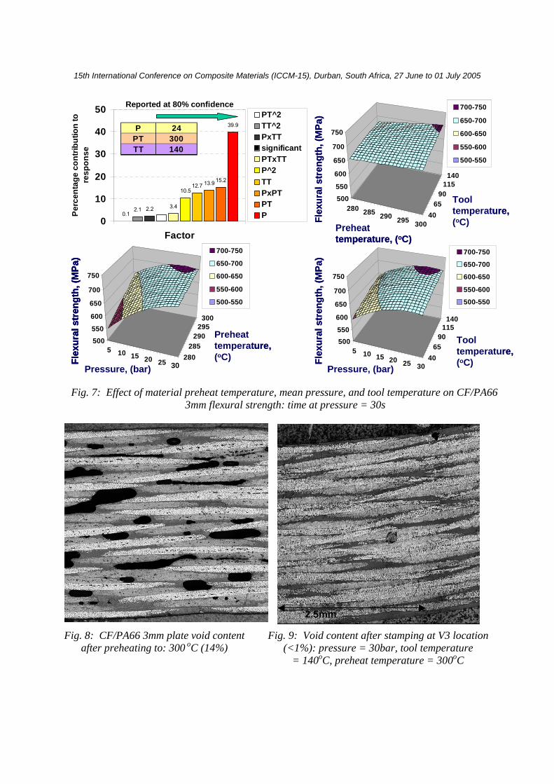
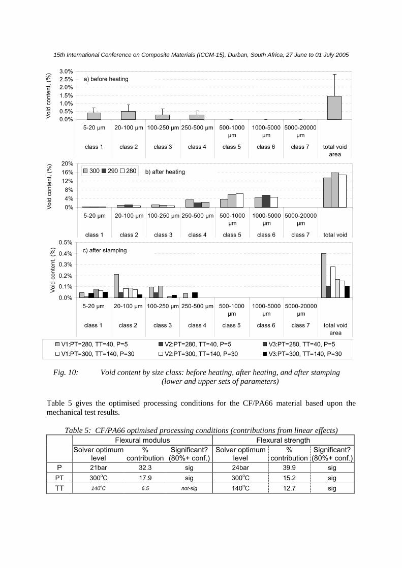
CF/PA66 sheet The effect of pressure, preheat temperature, and tool temperature was also studied (Table 4) on CF/PA66 flexural and tensile properties, with the effects on flexural strength again reported here as the most sensitive response. As with GF/PA6, a stamping rate of 166mm/s together with 30s time at pressure was used. The CF/PA66 preconsolidation state before stamping is shown in Figure 7. Regression model results are shown in Figure 8. Deconsolidation after heating was similar at temperatures of 280oC, 290oC, and 300oC. Hence the state at 300oC is shown in Figure 8, together with quality after stamping. Figure 9 shows the contribution to the total void area of each void feret diameter class before heating, after heating, and after stamping.
Table 4: CF/PA66 process study Pressure, (bar) Preheat temperature, (oC) Tool temperature, (oC) P PT TT
Low 5 280 40 Medium 17.5 290 90 high 30 300 140
It can be seen that the flexural stiffness was again increased by using higher tool temperatures and higher preheat temperatures (whist respecting degradation onset). Increased pressures again had the largest contribution towards maximising mechanical properties. Preheating showed similar levels of deconsolidation over a temperature range of 280-300oC, increasing plate void contents from 1.5% before heating to 15% after heating. However, the void content variation between the upper and lower set of parameters was lower after stamping than for the GF/PA6 sheet material, with good final consolidation levels and void contents of below 1%.
3mm
Fig. 7: CF/PA66 as supplied, 1.6% void content over 30mm
sample length
15th International Conference on Composite Materials (ICCM-15), Durban, South Africa, 27 June to 01 July 2005
0.12.1 2.2 3.4
10.512.7 13.9 15.2
39.9
0
10
20
30
40
50
Factor
Perc
enta
ge c
ontri
butio
n to
re
spon
se
PT^2TT^2PxTTsignificantPTxTTP^2TTPxPTPTP
280 285 290 295 30040
6590
115140
500550
600
650
700
750
700-750
650-700
600-650
550-600
500-550
Flex
ural
str
engt
h, (M
Pa)
Tooltemperature, (oC)Preheat
temperature, (oC)
280 285 290 295 30040
6590
115140
500550
600
650
700
750
700-750
650-700
600-650
550-600
500-550
Flex
ural
str
engt
h, (M
Pa)
Tooltemperature, (oC)Preheat
temperature, (oC)
5 10 15 20 25 3040
6590
115140
500550
600
650
700
750
700-750
650-700
600-650
550-600
500-550
Flex
ural
str
engt
h, (M
Pa)
Pressure, (bar)
Tooltemperature, (oC)
5 10 15 20 25 3040
6590
115140
500550
600
650
700
750
700-750
650-700
600-650
550-600
500-550
Flex
ural
str
engt
h, (M
Pa)
Pressure, (bar)
Tooltemperature, (oC)
Reported at 80% confidence
P 24PT 300TT 140
5 10 15 20 25280
285290
295300
500550
600
650
700
750
700-750
650-700
600-650
550-600
500-550
Flex
ural
str
engt
h, (M
Pa)
Pressure, (bar) 30
Preheat temperature, (oC)
5 10 15 20 25280
285290
295300
500550
600
650
700
750
700-750
650-700
600-650
550-600
500-550
Flex
ural
str
engt
h, (M
Pa)
Pressure, (bar) 30
5 10 15 20 25280
285290
295300
500550
600
650
700
750
700-750
650-700
600-650
550-600
500-550
Flex
ural
str
engt
h, (M
Pa)
Pressure, (bar) 30
Preheat temperature, (oC)
Fig. 7: Effect of material preheat temperature, mean pressure, and tool temperature on CF/PA66 3mm flexural strength: time at pressure = 30s
Fig. 9: Void content after stamping at V3 location (<1%): pressure = 30bar, tool temperature
= 140oC, preheat temperature = 300oC
Fig. 8: CF/PA66 3mm plate void content after preheating to: 300 oC (14%)
2.5mm
15th International Conference on Composite Materials (ICCM-15), Durban, South Africa, 27 June to 01 July 2005
Table 5 gives the optimised processing conditions for the CF/PA66 material based upon the mechanical test results.
Table 5: CF/PA66 optimised processing conditions (contributions from linear effects) Flexural modulus Flexural strength
Solver optimumlevel
% contribution
Significant? (80%+ conf.)
Solver optimumlevel
% contribution
Significant?(80%+ conf.)
P 21bar 32.3 sig 24bar 39.9 sig PT 300oC 17.9 sig 300oC 15.2 sig TT 140oC 6.5 not-sig 140oC 12.7 sig
0.0%0.5%1.0%1.5%2.0%2.5%3.0%
5-20 µm 20-100 µm 100-250 µm 250-500 µm 500-1000µm
1000-5000µm
5000-20000µm
class 1 class 2 class 3 class 4 class 5 class 6 class 7 total voidarea
Void
con
tent
, (%
)
0%4%8%
12%16%20%
5-20 µm 20-100 µm 100-250 µm 250-500 µm 500-1000µm
1000-5000µm
5000-20000µm
class 1 class 2 class 3 class 4 class 5 class 6 class 7 total voidarea
Void
con
tent
, (%
)
300 290 280
0.0%
0.1%
0.2%
0.3%
0.4%
0.5%
5-20 µm 20-100 µm 100-250 µm 250-500 µm 500-1000µm
1000-5000µm
5000-20000µm
class 1 class 2 class 3 class 4 class 5 class 6 class 7 total voidarea
Void
con
tent
, (%
)
V1:PT=280, TT=40, P=5 V2:PT=280, TT=40, P=5 V3:PT=280, TT=40, P=5V1:PT=300, TT=140, P=30 V2:PT=300, TT=140, P=30 V3:PT=300, TT=140, P=30
Fig. 10: Void content by size class: before heating, after heating, and after stamping (lower and upper sets of parameters)
a) before heating
b) after heating
c) after stamping
15th International Conference on Composite Materials (ICCM-15), Durban, South Africa, 27 June to 01 July 2005
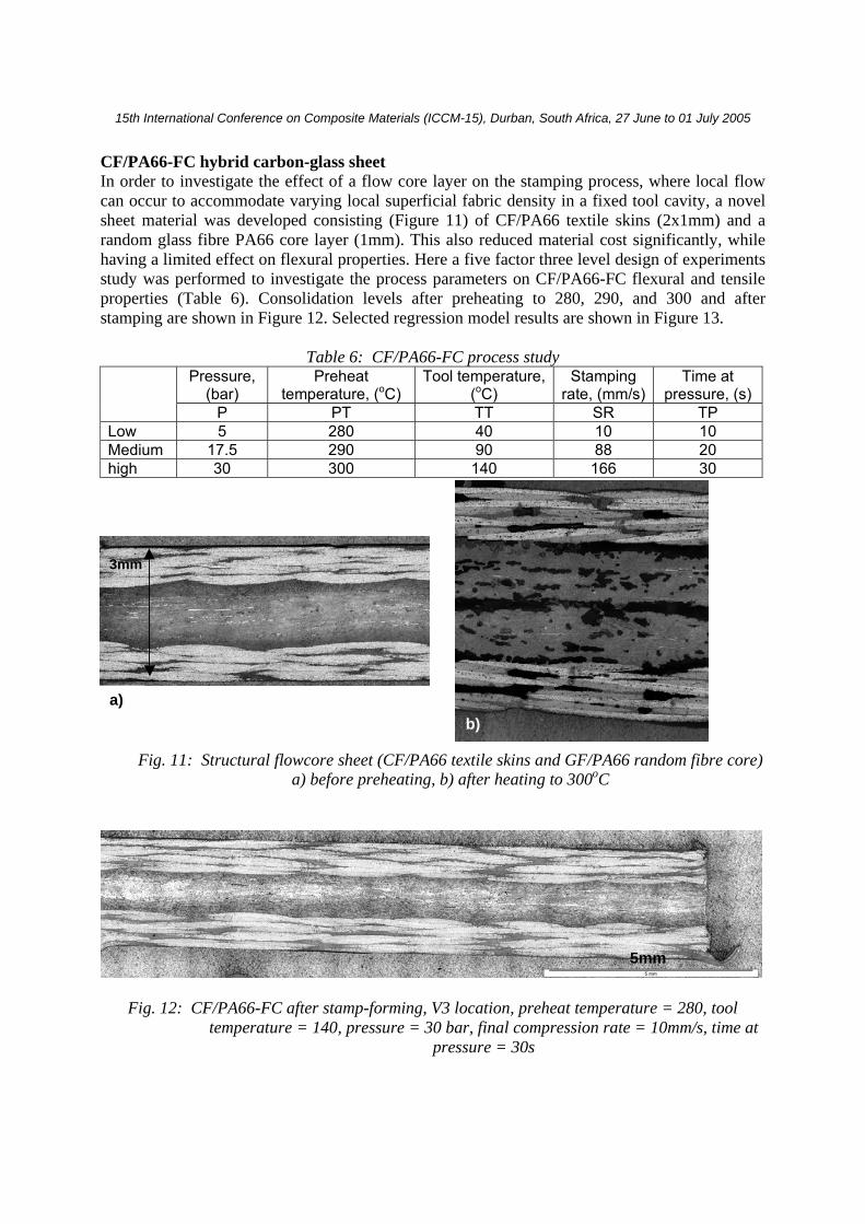
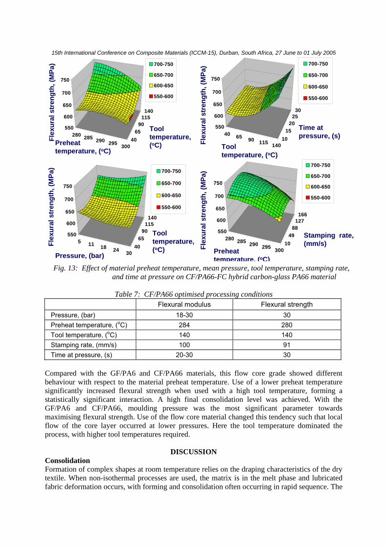
CF/PA66-FC hybrid carbon-glass sheet In order to investigate the effect of a flow core layer on the stamping process, where local flow can occur to accommodate varying local superficial fabric density in a fixed tool cavity, a novel sheet material was developed consisting (Figure 11) of CF/PA66 textile skins (2x1mm) and a random glass fibre PA66 core layer (1mm). This also reduced material cost significantly, while having a limited effect on flexural properties. Here a five factor three level design of experiments study was performed to investigate the process parameters on CF/PA66-FC flexural and tensile properties (Table 6). Consolidation levels after preheating to 280, 290, and 300 and after stamping are shown in Figure 12. Selected regression model results are shown in Figure 13.
Table 6: CF/PA66-FC process study Pressure,
(bar) Preheat
temperature, (oC) Tool temperature,
(oC) Stamping
rate, (mm/s) Time at
pressure, (s)
P PT TT SR TP Low 5 280 40 10 10 Medium 17.5 290 90 88 20 high 30 300 140 166 30
Fig. 12: CF/PA66-FC after stamp-forming, V3 location, preheat temperature = 280, tool
temperature = 140, pressure = 30 bar, final compression rate = 10mm/s, time at pressure = 30s
Fig. 11: Structural flowcore sheet (CF/PA66 textile skins and GF/PA66 random fibre core) a) before preheating, b) after heating to 300oC
3mm
a) b)
5mm
15th International Conference on Composite Materials (ICCM-15), Durban, South Africa, 27 June to 01 July 2005
Table 7: CF/PA66 optimised processing conditions Flexural modulus Flexural strength
Pressure, (bar) 18-30 30 Preheat temperature, (oC) 284 280 Tool temperature, (oC) 140 140 Stamping rate, (mm/s) 100 91 Time at pressure, (s) 20-30 30
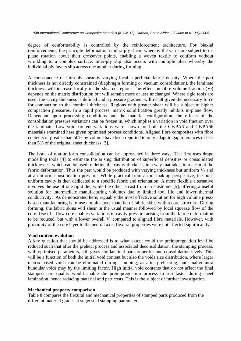
Compared with the GF/PA6 and CF/PA66 materials, this flow core grade showed different behaviour with respect to the material preheat temperature. Use of a lower preheat temperature significantly increased flexural strength when used with a high tool temperature, forming a statistically significant interaction. A high final consolidation level was achieved. With the GF/PA6 and CF/PA66, moulding pressure was the most significant parameter towards maximising flexural strength. Use of the flow core material changed this tendency such that local flow of the core layer occurred at lower pressures. Here the tool temperature dominated the process, with higher tool temperatures required.
DISCUSSION Consolidation Formation of complex shapes at room temperature relies on the draping characteristics of the dry textile. When non-isothermal processes are used, the matrix is in the melt phase and lubricated fabric deformation occurs, with forming and consolidation often occurring in rapid sequence. The
5 11 18 24 3040
6590
115140
550
600
650
700
750
700-750
650-700
600-650
550-600
Flex
ural
str
engt
h, (M
Pa)
Pressure, (bar)
Tooltemperature, (oC)
40 65 90 115 14010
1520
2530
550
600
650
700
750
700-750
650-700
600-650
550-600
Flex
ural
str
engt
h, (M
Pa)
Tooltemperature, (oC)
Time at pressure, (s)
280 285 290 295 30010
4988
127166
550
600
650
700
750
700-750
650-700
600-650
550-600Fl
exur
al s
tren
gth,
(MPa
)
Stamping rate, (mm/s)
Preheattemperature, (oC)
280 285 290 295 30040
6590
115140
550
600
650
700
750
700-750
650-700
600-650
550-600
Flex
ural
str
engt
h, (M
Pa)
Preheattemperature, (oC)
Tooltemperature, (oC)
Fig. 13: Effect of material preheat temperature, mean pressure, tool temperature, stamping rate, and time at pressure on CF/PA66-FC hybrid carbon-glass PA66 material
15th International Conference on Composite Materials (ICCM-15), Durban, South Africa, 27 June to 01 July 2005
degree of conformability is controlled by the reinforcement architecture. For biaxial reinforcements, the principle deformation is intra-ply shear, whereby the yarns are subject to in-plane rotation about their crossover points, enabling a woven textile to conform without wrinkling to a complex surface. Inter-ply slip also occurs with multiple plies whereby the individual ply layers slip across one another during forming. A consequence of intra-ply shear is varying local superficial fabric density. Where the part thickness is not directly constrained (diaphragm forming or vacuum consolidation), the laminate thickness will increase locally in the sheared region. The effect on fibre volume fraction (Vf) depends on the matrix distribution but will remain more or less unchanged. Where rigid tools are used, the cavity thickness is defined and a pressure gradient will result given the necessary force for compaction to the nominal thickness. Regions with greater shear will be subject to higher compaction pressures. In a rapid process, matrix solidification greatly inhibits in-plane flow. Dependant upon processing conditions and the material configuration, the effects of the consolidation pressure variations can be frozen in, which implies a variation in void fraction over the laminate. Low void content variations were shown for both the GF/PA6 and CF/PA66 materials examined here given optimised process conditions. Aligned fibre composites with fibre contents of greater than 50% by volume have been reported to only adapt to gap tolerances of less than 5% of the original sheet thickness [3]. The issue of non-uniform consolidation can be approached in three ways. The first uses drape modelling tools [4] to estimate the arising distribution of superficial densities or consolidated thicknesses, which can be used to define the cavity thickness in a way that takes into account the fabric deformation. Thus the part would be produced with varying thickness but uniform Vf and at a uniform consolidation pressure. While practical from a tool-making perspective, the non-uniform cavity is then dedicated to a specific fabric and orientation. A more flexible alternative involves the use of one rigid die, while the other is cast from an elastomer [5], offering a useful solution for intermediate manufacturing volumes due to limited tool life and lower thermal conductivity. As demonstrated here, arguably the most effective solution for high volume press-based manufacturing is to use a multi-layer material of fabric skins with a core structure. During forming, the fabric skins will shear in the usual manner followed by local squeeze flow of the core. Use of a flow core enables variations in cavity pressure arising from the fabric deformation to be reduced, but with a lower overall Vf compared to aligned fibre materials. However, with proximity of the core layer to the neutral axis, flexural properties were not affected significantly. Void content evolution A key question that should be addressed is to what extent could the preimpregnation level be reduced such that after the preheat process and associated deconsolidation, the stamping process, with optimised parameters, still gives similar final part properties and consolidation levels. This will be a function of both the initial void content but also the voids size distribution, where larger matrix based voids can be eliminated during stamping, as after preheating, but smaller intra bundular voids may by the limiting factor. High initial void contents that do not affect the final stamped part quality would enable the preimpregnation process to run faster during sheet lamination, hence reducing material and part costs. This is the subject of further investigation. Mechanical property comparison Table 8 compares the flexural and mechanical properties of stamped parts produced from the different material grades at suggested stamping parameters.
15th International Conference on Composite Materials (ICCM-15), Durban, South Africa, 27 June to 01 July 2005
Table 8: Comparison of flexural and tensile mechanical properties Suggested stamping
parameters Material code
P TP PT TT SR
E flex., (GPa)
σ flex., (MPa)
E tens., (GPa)
σ tens., (MPa) ε fail, (%)
GF/PP 220 14.5 280 14.7 370 3.0 GMTex 230 14.5 288 16.2 329 2.8 GMCTex 230 38.7 285 33.8 334 0.97 NMTex 190
80
13.2 204 12.9 219 2.4 GF/PA6 270 140
166
19.3 600 22.9 405 2.1 GF/PA6-FC - 140 - 20.2 530 19.7 305 2.1 CF/PA66 300 140 166 45.1 701 53.0 518 0.98 CF/PA66-FC
30 30
280 140 100 47.7 701 41.2 442 1.1
CONCLUSIONS Stamping trials were performed with thermoplastic composite materials. For monolithic GF/PA6 and CF/PA66 textile materials, the forming pressure was the dominating parameter. Use of a flow core layer (random GF) with carbon textile skins reduced the importance of forming pressure increasing the processing window. This had only a minor effect on mechanical properties while also reducing cost. Increasing tool temperatures from 40oC to 140oC showed an important effect for all materials. With optimised processing conditions, void contents could be reduced to levels below those in the initial sheets, and generally to below 1% across the stamped parts.
ACKNOWLEDGEMENTS This work was supported by Ford Motor Company. The authors wish to acknowledge and thank: EPFL (M. Kohler, L. Munsch, F. Demarco, and student assistants), Ford (D. Houston, R. Hooper, and E. Kleven). Materials were supplied by the following companies: SaintGobain Vetrotex International, Bond laminates, Quadrant plastic composites, Schappe Techniques.
REFERENCES 1. Wakeman, M.D., Zingraff, L., Blanchard, P., Bourban, P-E., Månson, J-A.E., “Stamp
forming of carbon fibre/PA12 composites – a comparison of a reactive impregnation process and a commingled yarn system”, submitted to Composites Science and Technology, November 2004
2. Wakeman, M.D., Kohler, M., Månson, J.-A. E., Blanchard, P., “Stamp-forming of reactive-thermoplastic carbon fibre/PA12 composite sheet”, FPCM7 – International Conference on Flow Processes in Composite Materials, CCM, Delaware, USA
3. Breuer U, Neitzel M, ‘The challenge of stamp forming high-strength thermoplastic composites for transportation’, 42nd International SAMPE Symposium, 1997.
4. Long A.C., Rudd C.D., ‘A simulation of reinforcement deformation during the production of preforms for liquid moulding processes’, Proceedings of the Institution of Mechanical Engineers Journal of Engineering Manufacture, 1994, 208, 269-278.
5. Robroek L, ‘The development of rubber forming as a rapid thermoforming technique for continuous fibre reinforced thermoplastic composites’, PhD Thesis, Structures and Materials Laboratory, Delft University of Technology, 1994.


![pascal.frossard@epfl.ch arXiv:1610.08401v1 [cs.CV] 26 … · Universal adversarial perturbations Seyed-Mohsen Moosavi-Dezfooli y seyed.moosavi@epfl.ch Alhussein Fawzi alhussein.fawzi@epfl.ch](https://img.pdfslide.net/doc/110x75/5aeb0a947f8b9a36698dd145/epflch-arxiv161008401v1-cscv-26-adversarial-perturbations-seyed-mohsen.jpg)