Embed Size (px)
Citation preview
ISSN (Print) : 2320 – 3765 ISSN (Online): 2278 – 8875
International Journal of Advanced Research in Electrical,
Electronics and Instrumentation Engineering (An ISO 3297: 2007 Certified Organization)
Vol. 3, Issue 5, May 2014
Copyright to IJAREEIE www.ijareeie.com 9370
Fuzzy Logic Controlled PV Powered Buck Converter with MPPT
Dr.Bos Mathew Jos1, Abhijith S2.Aswin Venugopal3, Basil Roy4, Dhanesh R5
Associate Professor, Dept. of EEE, Mar Athanasius College of Engineering, Kothamangalam, Kerala, India1 UG Student, Dept. of EEE, Mar Athanasius College of Engineering, Kothamangalam, Kerala, India2, 3, 4, 5
ABSTRACT: PV panels have become increasingly popular as a source of electricity owing to the environmental benefits and subsidies provided by the government. Major disadvantage of PV panels is that the output power is not constant and depends on the availability of sunlight. Many types of converters have been designed to regulate the output voltage and use it to charge battery system. The aim of this project is to design and implement a fuzzy logic controlled DC-DC converter system that regulates the output voltage, uses an MPPT tracking algorithm to maximize power and simultaneously supports a battery system and dc loads. The system was designed in MATLAB/Simulink. The performance of various fuzzy membership functions is compared. Hardware implementation was done using ATmega32 8-bit microcontroller. Perturb and Observe MPPT algorithm maximizes the power drawn from the panel for a given irradiation. Significant improvements in power output is obtained which reduces total cost of installation and improves equipment life. KEYWORDS: Fuzzy logic, MPPT,PV Powered, Buck converter
I .INTRODUCTION
PV panels are nowadays widely for power generation owing to the rising fuel prices and environmental concerns. Power generation using PV panels can be done in large scale and small scale. Large scale plants utilize large no of PV modules connected so as to generate power in the range of megawatts. Such plants are increasingly becoming popular. Small scale plants can be used at homes to reduce dependency on utility thus saving on utility bills. In large scale plants no energy storing device is used and therefore the power generated is directly fed into the grid. On the other hand small scale plants at homes use a battery as storage device and use the stored energy as back up during power outages or for supplying whole or part of the load demand.
II RELATED WORKS
In the thesis, “Modelling and Simulation of PV Array with Boost Converter “byD. Das and S.K. Pradhan[1] the PV Array was interfaced with boost converter but there is no provision to get output voltage lower than input. Also no was nonlinear control another improvement of this was done byDr. T Govindraj and R. Rasila, in their project “Development of Fuzzy Logic Controller for DC-DC Buck Converter” a buck Converter interfaced with solar array using fuzzy logic. This improves the performance of the system but unable to get lower output voltage from the system [2].In another paper “Development of a DC-DC Buck Boost Converter Using Fuzzy Logic Control” by F.S. Jaber,buck boost converter with fuzzy logic controller is implemented. In the simulation result. Steady state error is more. In another paper by M. Sahin and H.I. Okumus, “Fuzzy Logic Controlled Buck Boost DC-DC Converter for Solar Energy-Battery System”solar panel interfaced with fuzzy logic converter. Different membership functions like Gaussian and trapezoidal functions tried. They find that Steady state error is more PI or PID controller required.
III. CIRCUIT DESCRIPTION
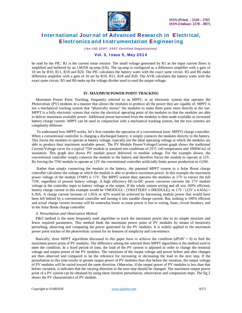
The buck mode DC/DC converter is made up of the synchronous MOSFET switches Q2 and Q3 and the energy storage devices inductor L1 and capacitors C1, C2, C9 and C10. Both the high side and low side MOSFETs are IRFZ44 N-fets. Nfets were chosen for their low Rdson to reduce resistance losses in the DC/DC converter. The input (C9, C10) and output capacitor (C2) are low ESR capacitors to handle the large current pulses from the switching DC/DC converter. The inductor value is 33uH and it is sized to handle 11 amps. D1 is a fast recovery diode used to conduct the
ISSN (Print) : 2320 – 3765 ISSN (Online): 2278 – 8875
International Journal of Advanced Research in Electrical,
Electronics and Instrumentation Engineering (An ISO 3297: 2007 Certified Organization)
Vol. 3, Issue 5, May 2014
Copyright to IJAREEIE www.ijareeie.com 9371
circulating current while the low side MOSFET is turning on. C15 and R8 are a snubber network used to cut down on some of the electrical noise generated by the switching current in the inductor. R25 drains the current out of the gate on the low side switch to make sure it is off when the power is shut off. The input power connector (to the solar panels) is the screw terminal J4. J3 is the output screw terminal connector (to the battery). F1 is the 10A safety fuse
The third MOSFET Q1 is added to allow the system to be turned off when connected to a battery. In the PPT Q2 and Q3 are shut off at night when there is not enough solar power to charge the battery. The microprocessor also should shut off when there is no longer any solar power to run it. However, the body diode in the high side MOSFET Q2 will conduct power in the reverse direction from the battery to the rest of the PPT and the system can never be shut off. Q1 is installed so its body diode blocks the reverse current flow. Q1 is driven by the top gate drive of the IR2104 MOSFET driver the same as the high side switch Q2. D2 keeps the gate on Q1 charged so Q1 is on all the time instead switching like Q2. This is more efficient because Q1 will not be switching so it dissipates less power. R24 drains the charge on the gate when the driver is shut off so the system will shut off.
The synchronous MOSFET gate driver U2 is an IR2104. It drives the high and the low side MOSFETs using the PWM signal from the microprocessor (on IN pin 6). D4 and C3 are part of the bootstrap circuit that generates the high side gate drive voltage for Q1 and Q2. When a N-fet MOSFET is used as the high side switch the gate voltage to drive it must be at 10v greater than the source voltage. Since the source voltage is the input voltage on the high side MOSFET the gate driver chip must generate a higher voltage that the input voltage to turn on the high side switch.
Fig 1 Circuit diagram
The DC/DC converter is controlled by the AVR ATmega 32 microcontroller the microcontroller is clocked at 20 MHz by the crystal XTAL1. The 5v to power the AVR is generated by a 78M05 (U3) linear voltage regulator. C4 and C7 are power supply smoothing capacitors. The PWM output of the PIC on pin 13 is used to control the duty cycle of the DC/DC converter which sets its voltage conversion ratio. The frequency of the PWM is set to 125 KHz by the AVR software. The PWM duty cycle is controlled by the AVR software to optimize the power output from the solar panels.
The AVR calculates the solar watts generated by reading the voltage and current of the solar panels through the A/D converter on pins 2 and 3. R3 and R4 make a voltage divider used to drop the input voltage into the 5v range that can
ISSN (Print) : 2320 – 3765 ISSN (Online): 2278 – 8875
International Journal of Advanced Research in Electrical,
Electronics and Instrumentation Engineering (An ISO 3297: 2007 Certified Organization)
Vol. 3, Issue 5, May 2014
Copyright to IJAREEIE www.ijareeie.com 9372
be read by the PIC. R1 is the current sense resistor. The small voltage generated by R1 as the input current flows is amplified and buffered by an LM358 op-amp (U6). The op-amp is configured as a difference amplifier with a gain of 10 set by R10, R11, R18 and R20. The PIC calculates the battery watts with the exact same circuit. R5 and R6 make difference amplifier with a gain of 10 set by R10, R11, R18 and R20. The AVR calculates the battery watts with the exact same circuit. R5 and R6 make up the voltage divider used to read the output voltage.
IV. MAXIMUM POWER POINT TRACKING
Maximum Power Point Tracking, frequently referred to as MPPT, is an electronic system that operates the Photovoltaic (PV) modules in a manner that allows the modules to produce all the power they are capable of. MPPT is not a mechanical tracking system that “physically moves” the modules to make them point more directly at the sun. MPPT is a fully electronic system that varies the electrical operating point of the modules so that the modules are able to deliver maximum available power. Additional power harvested from the modules is then made available as increased battery charge current. MPPT can be used in conjunction with a mechanical tracking system, but the two systems are completely different
To understand how MPPT works, let’s first consider the operation of a conventional (non- MPPT) charge controller. When a conventional controller is charging a discharged battery, it simply connects the modules directly to the battery. This forces the modules to operate at battery voltage, typically not the ideal operating voltage at which the modules are able to produce their maximum available power. The PV Module Power/Voltage/Current graph shows the traditional Current/Voltage curve for a typical 75W module at standard test conditions of 25°C cell temperature and 1000W/m2 of insolation. This graph also shows PV module power delivered vs module voltage. For the example shown, the conventional controller simply connects the module to the battery and therefore forces the module to operate at 12V. By forcing the 75W module to operate at 12V the conventional controller artificially limits power production to »53W.
Rather than simply connecting the module to the battery, the patented MPPT system in a Solar Boost charge controller calculates the voltage at which the module is able to produce maximum power. In this example the maximum power voltage of the module (VMP) is 17V. The MPPT system then operates the modules at 17V to extract the full 75W, regardless of present battery voltage. A high efficiency DC-to-DC power converter converts the 17V module voltage at the controller input to battery voltage at the output. If the whole system wiring and all was 100% efficient, battery charge current in this example would be VMODULE / (VBATTERY x IMODULE), or 17V / (12V x 4.45A) = 6.30A. A charge current increase of 1.85A or 42% would be achieved by harvesting module power that would have been left behind by a conventional controller and turning it into useable charge current. But, nothing is 100% efficient and actual charge current increase will be somewhat lower as some power is lost in wiring, fuses, circuit breakers, and in the Solar Boost charge controller
A Perturbation and Observation Method P&O method is the most frequently used algorithm to track the maximum power due to its simple structure and
fewer required parameters. This method finds the maximum power point of PV modules by means of iteratively perturbing, observing and comparing the power generated by the PV modules. It is widely applied to the maximum power point tracker of the photovoltaic system for its features of simplicity and convenience.
Basically, three MPPT algorithms discussed in this paper have to achieve the condition (dP/dV = 0) to find the maximum power point of PV modules. The difference among the selected three MPPT algorithms is the method used to meet the condition. In a fixed period of time, the load of the PV system is adjusted in order to change the terminal voltage and output power of the PV modules. The variations of the output voltage and power before and after changes are then observed and compared to be the reference for increasing or decreasing the load in the next step. If the perturbation in this time results in greater output power of PV modules than that before the variation, the output voltage of PV modules will be varied toward the same direction. Otherwise, if the output power of PV modules is less than that before variation, it indicates that the varying direction in the next step should be changed. The maximum output power point of a PV system can be obtained by using these iterative perturbation, observation and comparison steps. The fig 2 shows the PV characteristics of PV module.
ISSN (Print) : 2320 – 3765 ISSN (Online): 2278 – 8875
International Journal of Advanced Research in Electrical,
Electronics and Instrumentation Engineering (An ISO 3297: 2007 Certified Organization)
Vol. 3, Issue 5, May 2014
Copyright to IJAREEIE www.ijareeie.com 9373
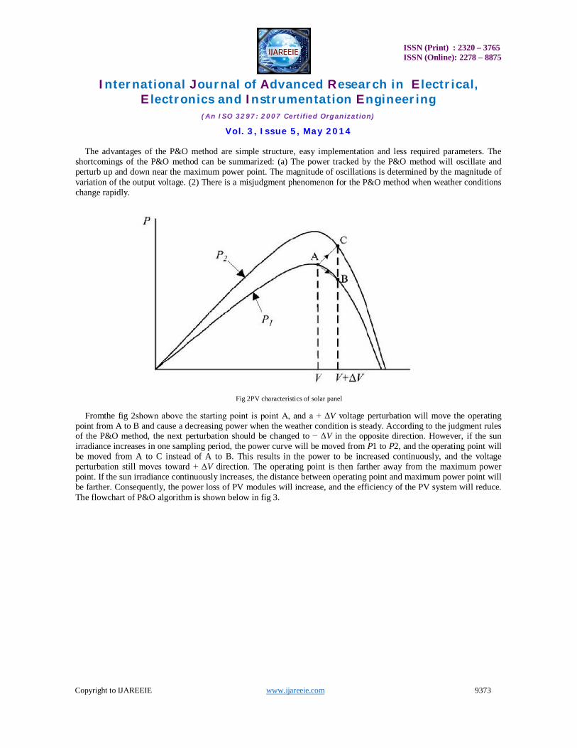
The advantages of the P&O method are simple structure, easy implementation and less required parameters. The shortcomings of the P&O method can be summarized: (a) The power tracked by the P&O method will oscillate and perturb up and down near the maximum power point. The magnitude of oscillations is determined by the magnitude of variation of the output voltage. (2) There is a misjudgment phenomenon for the P&O method when weather conditions change rapidly.
Fig 2PV characteristics of solar panel
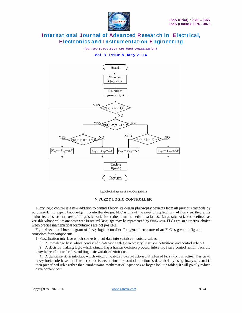
Fromthe fig 2shown above the starting point is point A, and a + ΔV voltage perturbation will move the operating point from A to B and cause a decreasing power when the weather condition is steady. According to the judgment rules of the P&O method, the next perturbation should be changed to − ΔV in the opposite direction. However, if the sun irradiance increases in one sampling period, the power curve will be moved from P1 to P2, and the operating point will be moved from A to C instead of A to B. This results in the power to be increased continuously, and the voltage perturbation still moves toward + ΔV direction. The operating point is then farther away from the maximum power point. If the sun irradiance continuously increases, the distance between operating point and maximum power point will be farther. Consequently, the power loss of PV modules will increase, and the efficiency of the PV system will reduce. The flowchart of P&O algorithm is shown below in fig 3.
ISSN (Print) : 2320 – 3765 ISSN (Online): 2278 – 8875
International Journal of Advanced Research in Electrical,
Electronics and Instrumentation Engineering (An ISO 3297: 2007 Certified Organization)
Vol. 3, Issue 5, May 2014
Copyright to IJAREEIE www.ijareeie.com 9374
Fig 3block diagram of P & O algorithm
V.FUZZY LOGIC CONTROLLER
Fuzzy logic control is a new addition to control theory, its design philosophy deviates from all previous methods by accommodating expert knowledge in controller design. FLC is one of the most of applications of fuzzy set theory. Its major features are the use of linguistic variables rather than numerical variables. Linguistic variables, defined as variable whose values are sentences in natural language may be represented by fuzzy sets. FLCs are an attractive choice when precise mathematical formulations are not possible.
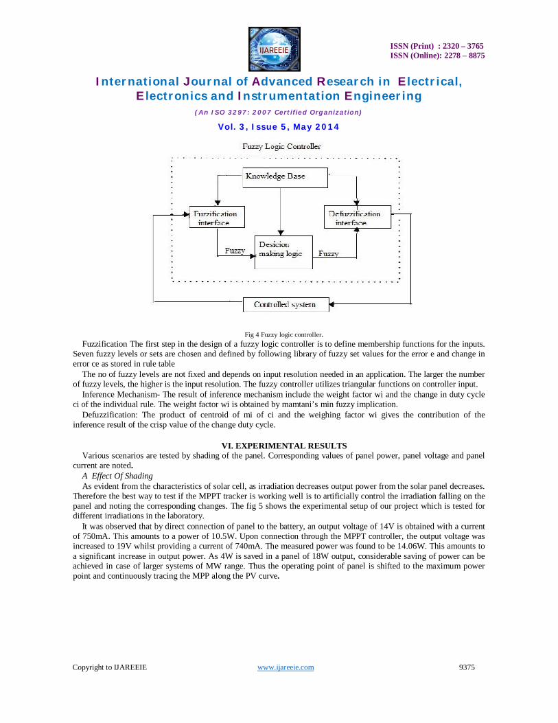
Fig 4 shows the block diagram of fuzzy logic controller The general structure of an FLC is given in fig and comprises four components.
1. Fuzzification interface which converts input data into suitable linguistic values. 2. A knowledge base which consist of a database with the necessary linguistic definitions and control rule set 3. A decision making logic which simulating a human decision process, infers the fuzzy control action from the
knowledge of control rules and linguistic variable definitions 4. A defuzzification interface which yields a nonfuzzy control action and inferred fuzzy control action. Design of
fuzzy logic rule based nonlinear control is easier since its control function is described by using fuzzy sets and if then predefined rules rather than cumbersome mathematical equations or larger look up tables, it will greatly reduce development cost
ISSN (Print) : 2320 – 3765 ISSN (Online): 2278 – 8875
International Journal of Advanced Research in Electrical,
Electronics and Instrumentation Engineering (An ISO 3297: 2007 Certified Organization)
Vol. 3, Issue 5, May 2014
Copyright to IJAREEIE www.ijareeie.com 9375
Fig 4 Fuzzy logic controller. Fuzzification The first step in the design of a fuzzy logic controller is to define membership functions for the inputs.
Seven fuzzy levels or sets are chosen and defined by following library of fuzzy set values for the error e and change in error ce as stored in rule table
The no of fuzzy levels are not fixed and depends on input resolution needed in an application. The larger the number of fuzzy levels, the higher is the input resolution. The fuzzy controller utilizes triangular functions on controller input.
Inference Mechanism- The result of inference mechanism include the weight factor wi and the change in duty cycle ci of the individual rule. The weight factor wi is obtained by mamtani’s min fuzzy implication.
Defuzzification: The product of centroid of mi of ci and the weighing factor wi gives the contribution of the inference result of the crisp value of the change duty cycle.
VI. EXPERIMENTAL RESULTS
Various scenarios are tested by shading of the panel. Corresponding values of panel power, panel voltage and panel current are noted.
A Effect Of Shading As evident from the characteristics of solar cell, as irradiation decreases output power from the solar panel decreases.
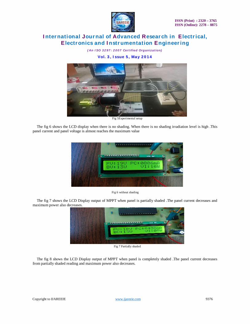
Therefore the best way to test if the MPPT tracker is working well is to artificially control the irradiation falling on the panel and noting the corresponding changes. The fig 5 shows the experimental setup of our project which is tested for different irradiations in the laboratory.
It was observed that by direct connection of panel to the battery, an output voltage of 14V is obtained with a current of 750mA. This amounts to a power of 10.5W. Upon connection through the MPPT controller, the output voltage was increased to 19V whilst providing a current of 740mA. The measured power was found to be 14.06W. This amounts to a significant increase in output power. As 4W is saved in a panel of 18W output, considerable saving of power can be achieved in case of larger systems of MW range. Thus the operating point of panel is shifted to the maximum power point and continuously tracing the MPP along the PV curve.
ISSN (Print) : 2320 – 3765 ISSN (Online): 2278 – 8875
International Journal of Advanced Research in Electrical,
Electronics and Instrumentation Engineering (An ISO 3297: 2007 Certified Organization)
Vol. 3, Issue 5, May 2014
Copyright to IJAREEIE www.ijareeie.com 9376
Fig 5Experimental setup
The fig 6 shows the LCD display when there is no shading. When there is no shading irradiation level is high .This
panel current and panel voltage is almost reaches the maximum value
Fig 6 without shading The fig 7 shows the LCD Display output of MPPT when panel is partially shaded .The panel current decreases and
maximum power also decreases.
Fig 7 Partially shaded
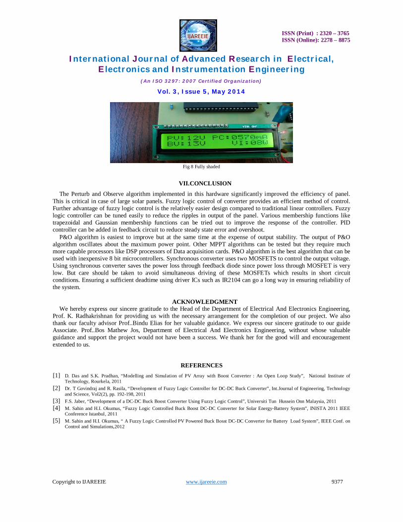
The fig 8 shows the LCD Display output of MPPT when panel is completely shaded .The panel current decreases
from partially shaded reading and maximum power also decreases.
ISSN (Print) : 2320 – 3765 ISSN (Online): 2278 – 8875
International Journal of Advanced Research in Electrical,
Electronics and Instrumentation Engineering (An ISO 3297: 2007 Certified Organization)
Vol. 3, Issue 5, May 2014
Copyright to IJAREEIE www.ijareeie.com 9377
Fig 8 Fully shaded
VII.CONCLUSION
The Perturb and Observe algorithm implemented in this hardware significantly improved the efficiency of panel. This is critical in case of large solar panels. Fuzzy logic control of converter provides an efficient method of control. Further advantage of fuzzy logic control is the relatively easier design compared to traditional linear controllers. Fuzzy logic controller can be tuned easily to reduce the ripples in output of the panel. Various membership functions like trapezoidal and Gaussian membership functions can be tried out to improve the response of the controller. PID controller can be added in feedback circuit to reduce steady state error and overshoot.
P&O algorithm is easiest to improve but at the same time at the expense of output stability. The output of P&O algorithm oscillates about the maximum power point. Other MPPT algorithms can be tested but they require much more capable processors like DSP processors of Data acquisition cards. P&O algorithm is the best algorithm that can be used with inexpensive 8 bit microcontrollers. Synchronous converter uses two MOSFETS to control the output voltage. Using synchronous converter saves the power loss through feedback diode since power loss through MOSFET is very low. But care should be taken to avoid simultaneous driving of these MOSFETs which results in short circuit conditions. Ensuring a sufficient deadtime using driver ICs such as IR2104 can go a long way in ensuring reliability of the system.
ACKNOWLEDGMENT
We hereby express our sincere gratitude to the Head of the Department of Electrical And Electronics Engineering, Prof. K. Radhakrishnan for providing us with the necessary arrangement for the completion of our project. We also thank our faculty advisor Prof..Bindu Elias for her valuable guidance. We express our sincere gratitude to our guide Associate. Prof..Bos Mathew Jos, Department of Electrical And Electronics Engineering, without whose valuable guidance and support the project would not have been a success. We thank her for the good will and encouragement extended to us.
REFERENCES [1] D. Das and S.K. Pradhan, “Modelling and Simulation of PV Array with Boost Converter : An Open Loop Study”, National Institute of
Technology, Rourkela, 2011 [2] Dr. T Govindraj and R. Rasila, “Development of Fuzzy Logic Controller for DC-DC Buck Converter”, Int.Journal of Engineering, Technology
and Science, Vol2(2), pp. 192-198, 2011 [3] F.S. Jaber, “Development of a DC-DC Buck Boost Converter Using Fuzzy Logic Control”, Universiti Tun Hussein Onn Malaysia, 2011 [4] M. Sahin and H.I. Okumus, “Fuzzy Logic Controlled Buck Boost DC-DC Converter for Solar Energy-Battery System”, INISTA 2011 IEEE
Conference Istanbul, 2011 [5] M. Sahin and H.I. Okumus, “ A Fuzzy Logic Controlled PV Powered Buck Bosst DC-DC Converter for Battery Load System”, IEEE Conf. on
Control and Simulations,2012