Embed Size (px)
Citation preview
IEEE TRANSACTIONS ON COMPUTERS, VOL. c-35, NO. 1, JANUARY 1986
Partitioning and Mapping Algorithmsinto Fixed Size Systolic Arrays
DAN I. MOLDOVAN, MEMBER, IEEE, AND JOSE A. B. FORTES, MEMBER, IEEE
Abstract -A technique for partitioning and mapping algo-rithms into VLSI systolic arrays is presented in this paper. Algo-rithm partitioning is essential when the size of a computationalproblem is larger than the size of the VLSI array intended for thatproblem. Computational models are introduced for systolic ar-rays and iterative algorithms. First, we discuss the mapping ofalgorithms into arbitrarily large size VLSI arrays. This mappingis based on the idea of algorithm transformations. Then, wepresent an approach to algorithm partitioning which is also basedon algorithm transformations. Our approach to the partitioningproblem is to divide the algorithm index set into bands and to mapthese bands into the processor space. The partitioning and map-ping technique developed throughout the paper is summarized asa six step procedure. A computer program implementing thisprocedure was developed, and some results obtained with thisprogram are presented.
Index Terms -Algorithm models, algorithm partitioning,algorithm transformations, VLSI algorithms, VLSI architectures.
I. INTRODUCTION
T HE partitioning of algorithms is basically motivated bythe simple fact that, often, the size of a computational
problem exceeds the size of a fixed VLSI structure intendedfor that problem. In the last few years, a number of VLSIprocessing arrays have been proposed for algorithms withregular data flow [l]-[3]. These structures are characterizedby a high degree of modularity, absence of long data paths,localized connectivity for data transfer, limited capability ofthe processing elements, absence of central control, and sim-ple timing mechanisms. The rigidity of VLSI arrays, causedby their fixed size and fixed interconnections, is a seriousproblem which must be overcome before these devices willbecome widely used. The size of the VLSI arrays is con-strained by technological factors. There are also physicallimitations imposed by the number of I/O pins. While thelevel of integration is expected to continue to go up, the num-ber of pins will be limited to several hundreds; and this makesVLSI devices to be I/O bounded. A natural solution to the I/Oproblem, as well as to overcome the limited size of the array,is to divide the computational problem into smaller problems.
Manuscript received August 7, 1983; revised April 4, 1985. This work wassupported in part by the Joint Services Electronics Program under Con-tract F49620-81-C-0070 and the National Science Foundation under GrantECS-8307258.
D. I. Moldovan is with the Department of Electrical Engineering-Systems,University of Southern Califomia, Los Angeles, CA 90089.
J. A. B. Fortes is with the School of Electrical Engineering, Purdue Univer-sity, West Lafayette, IN 47907.IEEE Log Number 8406281.
The partitioning of algorithms for VLSI devices is not asimple problem for several reasons. First, partitioning mayintroduce undesired side effects degrading the numerical sta-bility of algorithms. Second, a poor allocation of compu-tations to processors may lower the speedup factor. This iscaused by the amount of overhead operations resulting fromcommunications between partitions. Related to this is alsothe amount of external storage and communication links in-troduced by partitioning.
A. Statement ofthe Problem
In this paper, we discuss the partitioning of some algo-rithms for the purpose of their implementation on systolicarrays of fixed size. We consider the class of algorithms withnested loops for which computations are almost identicalover the entire index space. Most of the algorithms used insignal processing, for example, fall into this category. Sys-tolic arrays have been recognized as good architectures forthis class of algorithms [1].
Consider a computational problem of size N. In this paperwe measure the size of the problem by the number of ele-ments in the index set, that is N = I, x I2x , , x Inwhere Ii indicates the number of elements along the ith coor-dinate of the index set. Other measures of the size of theproblem are possible, for instance the number of inputs,numbers of rows in a matrix, etc., The size of the VLSInetwork is expressed by the number of processors M. Weassume that N >> M.The partitioning problem can then be formulated as
follows: divide the computational problem into smaller sub-problems and map these subproblems into the VLSI network.The goals are as follows.
1) Accuracy of computation should not be affected by thepartitioning process.
2) The computation time of a partitioned algorithm is pro-portional only to the product of the number of partitions andthe time to process one partition. In other words, no addi-tional delays caused by the partitioning process are allowed.
3) Partitioning does not require any increase in the com-plexity of VLSI processors.
4) The amount of overhead in external hardware and ex-ternal communication caused by partitioning is as small aspossible.
These goals indicate that partitioning should be performedsuch that the side effects are minimized.Our approach to the partitioning problem is to divide the
index space into bands and to map these bands into the pro-cessor space. The partitioning of the index space is done by
0018-9340/86/0100-0001$01.00 C) 1986 IEEE
I
IEEE TRANSACTIONS ON COMPUTERS, VOL. c-35, NO. 1, JANUARY 1986
some hyperplanes such that when the index space is mappedinto VLSI array only near neighbor processor communi-cations are necessary for index points ,inside the bands, andcommunication between bands is done by some external first-in first-out queue registers.
In spite of its importance, the partitioning problem has notyet received much attention from researchers. Hiwang andChung [5] considered the partitioning of algorithms for LUdecomposition, inversion of nonsingular triangular matrices,and the solution of linear systems of equations. They pro-posed a set of four primitive chips which interconnectedproperly could solve the above algorithms. Johnson [6], [7]and Heller [8] considered the partitioning ofQR factorizationfor band matrices, and some other matrix computations onsmall arrays. Franklin et al. [9] studied the problem of par-titioning VLSI interconnection networks. The main obser-vation about these results is that, so far, researchers havefocused on specific algorithms and proposed partitioningsolutions only for these specific algQrithms. Issues related todata communication were tacitly ignored. Our approach tothe partitioning problem is more general, that is, it is appli-cable to any iterative algorithm. Some of our ideas wereinspired by the solution to the problem of computing uni-form recurrences, using a single processor with a finite fastmemory, described in [4].
This paper is organized as follows: In Section II, com-putational models are introduced for VLSI arrays and algo-rithms. These models are used in Section III where wepresent the mapping of algorithms into mesh connected ar-rays. The mapping of algorithms into systolic arrays is doneby relating these two models through a transformation func-tion. The problem of algorithm partitioning is introduced inSection IV through some examples. It is shown that the parti-tioning and the mapping of algorithms into array processorscan be done by the same transformation function as for thenonpartitioned case if only an extra constraint is satisfied.
In Section V, we discuss issues related to the selection ofalgorithm transformation function to minimize the processingtime and the interconnection complexity of the VLSI arrays.
In Section VI, the results of this paper are summarized intoa procedure for partitioning and mapping algorithms into afixed size systolic array. This discussion refers to the case ofpartitioned iterative algorithms and parallelepipedic VLSI ar-rays. Finally, some conclusions are given in Section VII.
II. MODELS FOR VLSI ARRAYS AND ALGORITHMS
In this section, we present a mathematical formalism formodeling VLSI arrays and algorithms. This formalism isnecessary for mapping algorithms into architectures and forpartitioning algorithms. In what follows we use symbol I todenote the set of nonnegative integers and Z to refer to the setof all integers. The nth cartesian powers of I and Z are de-noted as In and zn, respectively.
A. VLSI Array Model
We assume that the computational resource consists of amesh connected network of processing cells.
Definition 1: A mesh connected array processor is a tuple(Jfll, P) where J'-' C zn- is the index set of the array andp E z(nl)xr is a matrix of interconnection primitives.
Although we consider, for the sake of generality, that VLSIarrays a;e (n - 1)-dimensional, practical arrays have aplanar layout. The position of each processing cell in thearray is described by its cartesian coordinates. The inter-connections between cells are described by the differencevectors between the coordinates of adjacent cells. The matrixof interconnection primitives is
(1)P = [PI P2... PS]where pj is a column vector indicating a unique direction ofa communication link.
Consider, for example, the array shown in Fig. 1; its modelis described as (J2, P) where
J2 = {(ji,j2): 0 C ji C 2, 0 ' j2 C 2}
1° 1-1-1 I 0 0 1-1Lo= 1 -1 I -1 I -1 0 O0 1j2-12
(2)
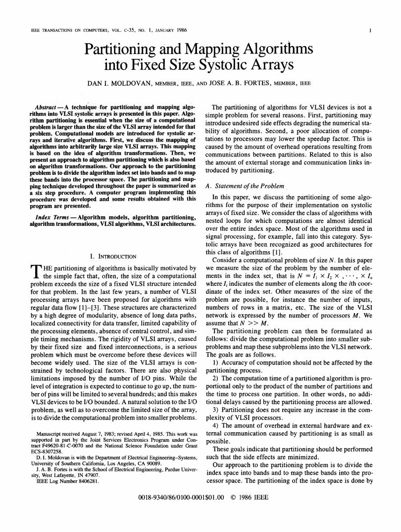
This array has 8-neighbor bidirectional connections and alsoa connection within the cell. Triangular systolic arrays havebeen proposed for algorithms such as matrix inversion, Cho-lesky decomposition, dynamic programming, and others.These arrays can also be modeled using definition 1. Forexample, the model for the array shown in Fig. 2 is (J2,p)where
2= {(j,J2),Jil 3, 0 i2 Jil}
P = p2 P3] = (3)
The structural details of the cells and the timing are derivedfrom algorithms which are mapped into such arrays. Forsimplicity, we consider that all cells are identical. If an algo-rithm requires an array with several different types of cells,then the model can be easily modified to describe the func-tions of each cell in index set J'-1.
B. Algorithm Model
In this paper, we consider the class of algorithms withnested loops. In order to partition and to map algorithms intoVLSI array processors, it is convenient to define an algorithmmodel. The important information about an algorithm whichwe want to include in the model is the algorithm index set, thecomputations performed at each index point, the data depen-dencies which ultimately dictate the algorithm communi-cation requirements and the algorithm input and outputvariables. In what follows, when we refer to an algebraicstructure and its carrier, we will use the same symbol.
Definition 2: An algorithm A over an algebraic structureS is a 5 tupleA = (Jn,C,D,X,Y) where:
J' is a finite index set of A, J" C In;C is a set of triples (j, V, t) where] E Jn, v is a variable and
t is a term built from operations of S and variables ranging
2
MOLDOVAN AND FORTES: PARTITIONING AND MAPPING ALGORITHMS INTO SYSTOLIC ARRAYS
Fig. 1. A square array with 8-neighbor connections.
Fig. 2. A triangular array with three interconnections.
over S. We call v the variable generated at], and any variableappearing in t is called a used variable.X is the set of input variables of A;D is a set of triples (j, v, d) where j E Jn, v is a variable
and d is an element of Zn.Y is the set of output variables of A.There are three types of dependencies in D.1) Input dependence; (1' v, d) is an input dependence if
v E X and v is an operand of t in computation (1, v, t); bydefinition d = 0.
2) Self dependence; (j, v, d) is a self dependence if v isone of the operands of t in computation (1, v, t); by definitiond = 0.
3) Internal dependence; (j, v, d) is an internal dependenceif v is an operand of t in (j, v, t) generated at (j *, v, t); bydefinitiond =17 J*.
It is convenient to represent dependencies D as a matrixD = [D' D'] where DO is a submatrix of D containing allinput and self-dependencies, and D' is the matrix of internaldependencies. Every column of D is the last element of thetriple (, v,d) and is labeled d3. If dependencies are validalmost in every point of the index set of the algorithm, thelabels of the columns of D need not be shown. Also, forpractical purposes self dependencies can be ignored. Con-sider the algorithm:
for jo = 1 to Nfor jl = 1 to N
for j2 = 1 toNS,: aa(jo,j1,J2) = a(jo -1,1S2: b(jo,jl,j2) = b(jo - 1, j
end 12end j1
end jo.
The model for this algorithm is found using definition 2.The index set is {J3 = (jo,jl,j2, 1 ' jo ' N, 1 ' jI ' N,1 . 12 C N}. The set of computations C is {(j a, a(jo -1,il + 1,J2) * b(jo - 1,11,I2 + 1)) and (j,b,b(jo- 1,i - 1,12 + 2) + b(jo, j - 3, j2 + 2))}. In this example, atevery point in the index space a multiplication and an addi-tion are performed. Between the variables generated atdifferent index points, there are some dependencies whichactually dictate the algorithm communication requirements.For example a(4, 5, 6) = a(3, 6, 6) * b(3, 5, 7). These de-pendencies can be described as difference vectors of indexpoints where a variable is used and where that variable wasgenerated. Four dependence vectors exist.
d, = (1, -1,0)' for pair (a(jo,]j,j2), a(o - 1,11 + 1,J2))d2 = (1, 0,-)' for pair (b(jo,j1,j2), b(jo - 1,J,J2 + 1))
d3 = (1,1, -2)' for pair (b(jo,jl,j2),b(jo- 1, -,j2 + 2))
d4= (0, 3, -2)' for pair (b(jO,j1,j2),b(jO,jj - 3,J2 + 2)).
With these dependencies we form a matrix D (the order ofcolumns is not important).
1 1 1 03D= d2 d3 d4]= L 0 -1 -2 2 (5)
a b b b
For this algorithm, all four dependence vectors exist inalmost every point of the index set; d1 is associated withvariable a and the rest with variable b. Notice that the inputdependencies were ignored here for the purpose of simplicity.The set of input variables X and the set of output variables Yare easily identified using indexes and are ignored here.The algorithm model from definition 2 is only a static
model in the sense that is does not indicate an executionordering on the index set. Notice that the index points in (4)for example, are ordered in lexicographical order. This is anartificial ordering and can be modified for the purpose ofparallelism extraction. Next, we define an execution orderingwhich must be associated to the algorithm model from defini-tion 2 in order to guarantee the correctness of computation.
Definition 3: The execution of an algorithm A = (Jfn, C,D, X, Y) is described by
1) the specification of a partial ordering o on Jn (calledexecution ordering) such that for all (d, v,J ) E DI we haved 0O (i.e., d larger than zero in the sense of mo);
+ 1,j2) * b(jo- ,J,J2 + 1)- 1,2 + 2) + b(jo,j - 3,J2 + 2)
(4)
3

IEEE TRANSACTIONS ON COMPUTERS, VOL. c-35, NO. 1, JANUARY 1986
2) the execution rule: until all computations in C havebeen performed, execute (J°, v, t) for all j j for which(j, v, t) have terminated.
In this paper, we use the ordering larger than zero (>) inlexicographical sense. Thus, if d = j -j * > 0 it meansthat computations indexed by j * must be performed beforethose indexed by 7. One immediate application of the algo-rithm model presented here is to study the question ofalgorithm equivalency. Often, we desire to change the fea-tures of an algorithm while preserviAng its equivalence incomputations. Two algorithms A and A are equivalent, writ-ten A =A, if they map any set of input variables into thesame set of output variables. The next cdefinition introducesa stronger equivalence criterion than this input-outputequivalence.
Definition 4: Two algorithms A = (Jfn, C,D,X, Y) andA = (Jn, C,D,X, Y) are said to be T equivalent if andonly if:
1) AlgorithmAisinput-outputequivalenttoA;A-A.A 2) Index set of A is the transformed index set of A;Jn = T(Jn) where T is a bijection function
3) to any operation of A it corresponds an identicaloperation in A and vice versa.
4) Dependencies ofA are the transformed dependenciesof A, written D = T(D).We are interested in transformed algorithms for which the
ordering imposed by the first coordinate of the index set is anexecution ordering. The motivation is that if only one coordi-nate of the index set preserves the correctness of computationby maintaining an execution ordering, then the rest of indexcoordinates can be selected by the algorithm designer to meetsome VLSI communication requirements. In what follows,we will indicate how a transformation T can be selected suchthat the transformed algorithm can be mapped into a VLSIarray and moreover, how an algorithm can be partitioned.
III. MAPPING ALGORlTHMS wnTo VLSI ARRAYs
A transformation which transforms an algorithm A into anA
algorithm A is defined as
T = , S (6)
where mapping HI and S are defined as I:J.. J1 andS: Jn -> Jjn-l. In this paper, we consider only linear trans-formations T, i.e., T E Znxn". Thus, algorithm dependenciesD are transformed into D = TD. The mapping H is selectedsuch that the transformed data dependence matrix D has posi-tive entries in the first row. This ensures a valid executionordering, and can be written as follows:
fd > 0 for any di E D . (7)
The immediate gain of this setting is that we can regardcorrectly the first coordinate of the transformed algorithm Joas the time coordinate. Thus, a computation indexed by
j E J' in the original algorithm will be processed at the time_A
Ilj = jo. Moreover, the total running time of the new algo-rithm is usually t = max Jo - min Jo + 1. This assumes aunitary time increment. In general, the time increment maynot be unitary; but it is given by the smallest transformeddependence, i.e., minimum II di. Thus, the execution time ofthe parallel algorithm is the number of hyperplanes HI sweep-ing the index space Jf and is given by the ratio
= [max (j j2) + 11mfnoa di
for any ",7'
E J' and -di E D.
The transformation S can then be selected such that the trans-formAed dependencies are mapped into a VLSI array modeledas (Jn-l, P). This can be written as
SD = PK (9)
where matrix K indicates the utilization of primitive inter-connections in matrix P. Matrix K = [kji] is such that
kji 2 0 (10)
Eki ' -Hdi.i
(11)
Expression (10) simply requires that all elements of Kmatrix are nonnegative and (11) requires that communicationof data associated with dependence di must be done usingsome primitives p, exactly Yj kji times. It is possible that someinterconnection primitives will not be used. These corre-spond to rows of matrix K with zero elements. Most often,many transformations S can be found, and each transfor-mation leads to a different array. This flexibility apparentlycomplicates matters, but in fact, it gives the designer thepossibility to choose between a large number of arrays withdifferent characteristics. As we will see, tradeoffs betweentime and space characteristics are possible.
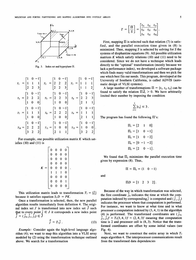
It can be seen from Fig. 3 that the index set for this ex-ample is a cube, and Hl contains the coefficients of a familyof parallel planes. The first index points visited by HI are(1, X, N) and the last are (N, X, 1) where X is don't care. Thenumber of parallel planes H necessary to cover all indexpoints in the cube represents the parallel processing time andis found from (8)
t = (N- 1)- (1-N) + 1 = 2N- 1.I
(12)
All index points which are contained in one plane HI at agiven moment can be processed in parallel because there areno dependencies between them and they obey equationH] = constant.The next step is to find transformation S. The program
found twelve S matrices which satisfy conditions (9)-(11).These S matrices, together with H selected above, formtwelve distinct valid transformations of the form T = [v]. Welist them here in order to discuss their merits.
4
(8)
MOLDOVAN AND FORTES: PARTMONING AND MAPPING ALGORITHMS INTO SYSTOLIC ARRAYS
Fig. 3. Index set and hyperplane HI.
-111
3]-1-2
oi-1-
oj
2
2j
-1 0 -1- -1 0-1-
T2 = 2 2 2 T3 I 1
-2 2 3 1 1 2--1 0 -1- I O -1-
T5 = 2 2 3 T6 =2 2 3
Ll 0 0 2 1 Ij-1 0 -1- -1 0 I-1
Tg = 2 2 2 Tg I=
-1 0 0- 2 1 Ij-1 0 -1 -1 0 -1
Tll =I1 0 0 T12 I 0 0.
L2 I 1j 3 2 2jFor example, one possible utilization matrix K which sat-
isfies (10) and (11) is
1 1 1 0O ,0 0 00000
O O 0 1K=0 0 0 0
This utilization matrix leads to transformation T7 = [g]
because it satisfies equation S7D = PK.Once a transformation is selected, then, the new parallel
algorithm results immediately from definition 4. The origi-nal index set J is transformed into new index set J suchthat to every point j E J it corresponds a new index pointi = (j0jJ,i2) E J
j = T7J. (13)
Example: Consider again the high-level language algo-rithm (4); we want to map this algorithm into a VLSI array
modeled by (2) using the transformation technique outlinedabove. We search for a transformation
[ ni] tll t12 t13
T t=21 t22 t23j-
t31 t32 t33J
First, mapping fH is selected such that relation (7) is satis-fied, and the parallel execution time given in (8) isminimized. Then, mapping S is selected by solving for S thesystems of diophantine equations (9). All possible utilizationmatrices K which satisfy relations (10) and (11) need to beconsidered. Since we do not have a technique which leadsdirectly to the "optimal" transformation (mostly because welack a performance index), we developed a software packagewhich finds many valid transformations and then we pick theone which best fits our needs. This program, developed at theUniversity of Southern California, is called ADVIS (auto-matic design of VLSI systems).A large number of transformations H1 = [t1l t12 t13] can be
found to satisfy the relation fldj > 0. We have arbitrarilylimited their number by imposing the condition
3
The program has found the following H's:
H1 =[2 1 0]
12 = [ 0 - 1]
3 = [1 0 -2]
114 = [0 -1 -2]
H5= [2 0 - 1].
We found that 12 minimizes the parallel execution timegiven by expression (8). Thus,
H= 2=(1 0 -1)
and
HID = [1 2 3 2].
Because of the way in which transformation was selected,the first coordinate jo indicates the time at which the com-
putation indexed by corresponding] is computed and ( 1j2)indicates the processor where that computation is performed.For instance, we want to know at what time and in whatprocessor a computation indexed by (3, 4, 1) in the algorithm(4) is performed. The transformed coordinates are (jo,j1,j2) = T7(3,4, 1)'= (2,8, 3)t meaning that computationtime is 2 and processor cell is (8, 3). Notice that the trans-formed coordinates are offset by some initial values (seeFig. 4).
Next, we want to construct the entire array in which T7maps algorithm 4. The interprocessor communications resultfrom the transformed data dependencies
41 0Ti = [ 1
-2 2
-I 0
T4 = 2 2
-1 0
-1 0
T7 = I II 0-I 0
TIo = 2 23 2
5

IEEE TRANSACTIONS ON COMPUTERS, VOL. c-35, NO. 1, JANUARY 1986
JO 21 J2 3 3 1jO il i2 time processor 3 3 3 0 9
_ ____ ------- 3 3 4 -1 101 1 1 0 3 1 3 11
1 1 2 -1 4 1 1 2 41 1 3 -2 5 1 4 1 91 1 4 -3 6 1 , 4 3 0 101 1 5 -4 7 1 4 4 -1 111 2 0 4 1 4 5 - 121 2 2 -1 5 1 2 91 2 3 -2 6 1 1 101 2 4 -3 7 1 0 111 2 5 -4 6 1 -1 121 3 1 0 £3 1 -2 1 31 3 c' -1 6 1 3 61 3 3 -2 7 1 4 1 L 2 71 3 4 -3 4, 1 9t 1 31 3 5 -4 9 1 '4 1 4 0 91 4 1 0 1 1 -1 101 4 2 -1 7 1 4 2 1 71 '4 3 -' a 1 42 2 2 2 11 4 4 -3 9 1 4 2 3 1 91 4 ', -4 10 1 4 2 4 0 101 i, 1 0 7 1 4 2 5 -1 111 5 2 -1 6 11D 3 -2 9 1 2 29
1 5 4 -3 10 1 4 3 3 1 101 5 5 -4 11 1 4 3 4 0 112 1 1 1 4 2 4 3 5 -1 12
c 1 cR C5 2 l! Lj 1 3 92 13 -1 6 2 4 te 2 2 10
2 1 4 -2 7 2 '44 1 11
2 1 5 -3 s 2 4 4 4 0 122 2 1 1 5 LI; di 5 _-1 132 2 2 0 G 2 5 1 3 1027 2 4 222 112 2 4 -2 ji 2 4 ;, 3 1 122 2 5 -3 9 2 4 ', 4 0 132 3 1 1 6 2 L: ', 5 -1 142 3 2 0 7 2 1 4 72 3 3 - 2'2 3 4 -2 9 2 32 3 D 10 2L 1 4 1 102 4 1 1 7 2 1 102 4 2 0 i9211 2 1 4 C,2 4 3 -1 4 2 '4 9
j 1 2 2~~~~~~~~~~~~3 12 4 4 -2 10 c ) e 3 2 102 4 5 -3 11 6' ', 6' 1l21 112 5 1 2 5 2 0 123 5 -20 9 2 1 4 32 5 3 -1 10 26 3 2 102 5 4 -2 11 2 3 2 112 5 5 -3 12 2 , 4 1 12
3 11 2 5 ~ ~~3 5 3 133 2 3 13 1 4 103 1 3 C] 7 , 4 2 3 113 1 4 -1 3 2 123 1 5 3 49 4 1 133 2 1 2 6 3L5 5 0 14L3 2 2 1 7 3 ' ', 1 4 1 13 2- 3 3 ; 2 3 123 2 4 - ,5 D 2 133 2 5 -2 10 3 5 1 i3 3 1 2 7 3 0 1'
Fig. 4. Mapping of index set into VLSI array (nonpartitioned case)u 0 -1
using transformation T = I I I-1 0 0-
^ ~~-I 0 -1- I I I O-D = T7D = I1L -1 0 1 3
LI 0 0 LO - 1 -2 -2]a b b b
-1 2 3 2= O O 0 1
1 1 1 0-a b b b
ii33333
3
3
4
4
444
444
I'
4
4
444"444
14
5c-
55
555
5
5
,.
5
5
55555
(14)
The first row of the transformed dependencies is IID =
[1 2 3 2]. Each element indicates the number of time unitsallowed for its respective variable to travel from the pro-cessor where it is generated to processor where it is used.Only two interconnection primitives are required, namely(0 1)' and (1 0)'. The VLSI array is shown in Fig. 5. Thiscorresponds to the fact that the utilization matrix K is verysparse; and in general, the simpler the K matrix is (lessnonzero elements and unity if possible) the simpler the VLSIarray we need. Notice that in this example we started with a
Fig. 5. VLSI array.
rather complex VLSI network model as a tentative solution,but due to the transformation technique presented here wefound that a much simpler array is actually needed. Thecomputer program ADVIS detects which is the trans-formation leading to the simplest array and for this exampleT7 was the "best." Following the same procedure, the readercan verify that any other of the twelve transformations foundabove leads to a more complex VLSI structure.
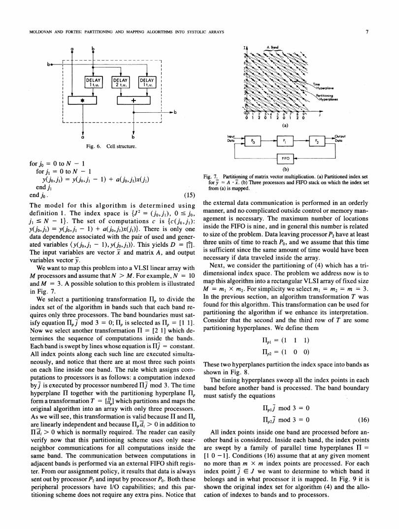
All cells in the array shown in Fig. 5 are identical, and thestructure of a cell results from the computations required bythe algorithm (4) as well as the timing and data commu-nication dictated by transformed data dependencies (14). Thestructure of the cell is shown in Fig. 6. It consists of an adder,multiplier, and delay elements. Notice that variable a whichhas a dependence d, moves from a cell to the next via avertical channel with direction (O 1)', and it has one unit timedelay in each cell (in the multiplier.) Variable b is used forthree operands, and each one has its own direction and timingaccording to the dependence obtained from the algorithm.For example variable b, which is the second multiplicationoperand, has dependence d2 and to this dependence it corre-sponds a vertical channel (O l)t and a delay of two time unitsbetween the moment when variable is generated and used;that is one unit delay must be inserted in front of the multi-plier for this operand. The operands for the adder are tracedin the same way. It is important to remark here that tradeoffsare possible between the time and space characteristics of theVLSI array. By simply selecting another transformation, itresults a different parallel execution time, different arraydimensions, different delays inside processing cells, and dif-ferent interprocessing connections. The program we devel-oped allows us to search for all possible transformations andto select the one which leads to the "optimum" array (in sameselected sense.)So far, we assumed arbitrarily large arrays. Next, we con-
sider the case when the size of the array is fixed. As we willsee, the mapping for this case can be done by the sametransformation if an additional constraint is satisfied.
IV. ALGORITHM PARTITIONING
In this section, we introduce our approach to the par-titioning problem through two examples and then we discussthe general case. The following Algol-like program describesan algorithm for the computation of a matrix-vector producty = Ai where A is an (N X N) matrix.
6
MOLDOVAN AND FORTES: PARTITIONING AND MAPPING ALGORITHMS INTO SYSTOLIC ARRAYS
2 0 1 2 0
(a)
Fig. 6. Cell structure.
for jo = Oto N - 1for]1 = Oto N - 1
y(jo,ji) = y(jo9j1 - 1) + a(jO,jl)x(j1)end j1
end jo. (15)The model for this algorithm is determined usingdefinition 1. The index space is {J2 = (jO1jl), 0 c Jo,j' s N - 1}. The set of computations c is {c(]o,j1):Y(1,09i) = y(jo9jl- 1) + a(jo,j1)x(j1)}. There is only onedata dependence associated with the pair of used and gener-ated variables (y(jo,jl - 1),y(joJI)). This yields D = [°].The input variables are vector x and matrix A, and outputvariables vector jy.We want to map this problem into a VLSI linear array with
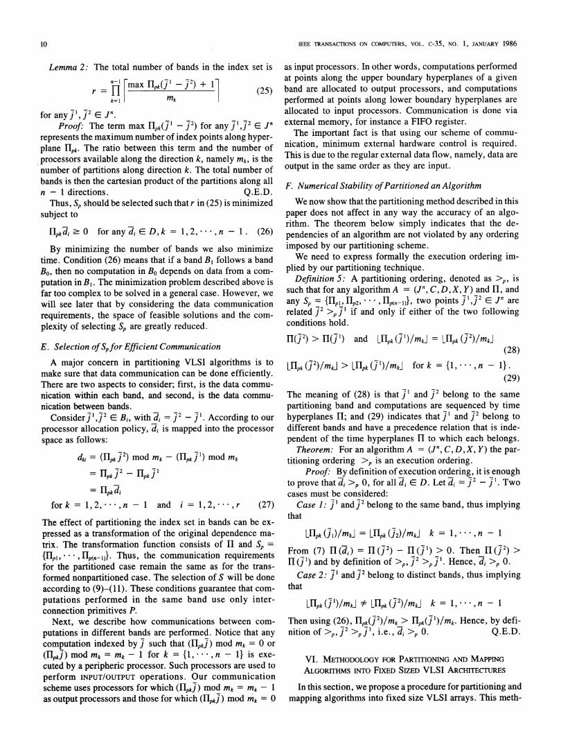
M processors and assume thatN > M. For example, N = 10andM = 3. A possible solution to this problem is illustratedin Fig. 7.We select a partitioning transformation flp to divide the
index set of the algorithm in bands such that each band re-quires only three processors. The band boundaries must sat-isfy equation HIpj mod 3 = 0; Hlp is selected as lIp = [1 1].Now we select another transformation Hl = [2 1] which de-termines the sequence of computations inside the bands.Each band is swept by lines whose equation is Hlj = constant.All index points along each such line are executed simulta-neously, and notice that there are at most three such pointson each line inside one band. The rule which assigns com-putations to processors is as follows: a computation indexedbyj is executed by processor numbered Hj mod 3. The timehyperplane Hl together with the partitioning hyperplane tipform a transformation T =[N] which partitions and maps theoriginal algorithm into an array with only three processors.As we will see, this transformation is valid because H and flpare linearly independent and because rlp di > 0 in addition toH di > 0 which is normally required. The reader can easilyverify now that this partitioning scheme uses only near-neighbor communications for all comnputations inside thesame band. The communication between computations inadjacent bands is performed via an external FIFO shift regis-ter. From our assignment policy, it results that data is alwayssent out by processor P2 and input by processor PO. Both theseperipheral processors have I/O capabilities; and this par-titioning scheme does not require any extra pins. Notice that
Input OutputData P P P Data
0 21
(b)Fig. 7. Partitioning of matrix vector multiplication. (a) Partitioned index set
for y = A * x. (b) Three processors and FIFO stack on which the index setfrom (a) is mapped.
the external data communication is performed in an orderlymanner, and no complicated outside control or memory man-agement is necessary. The maximum number of locationsinside the FIFO is nine, and in general this number is relatedto size of the problem. Data leaving processor P2 have at leastthree units of time to reach PO, and we assume that this timeis sufficient since the same amount of time would have beennecessary if data traveled inside the array.
Next, we consider the partitioning of (4) which has a tri-dimensional index space. The problem we address now is tomap this algorithm into a rectangular VLSI array of fixed sizeM = mI X iM2. For simplicity we selectM=mM2 = m = 3.In the previous section, an algorithm transformation T wasfound for this algorithm. This transformation can be used forpartitioning the algorithm if we enhance its interpretation.Consider that the second and the third row of T are somepartitioning hyperplanes. We define them
Hp=I(1 1 1)
HP2= (I 0 0)
These two hyperplanes partition the index space into bands asshown in Fig. 8.The timing hyperplanes sweep all the index points in each
band before another band is processed. The band boundarymust satisfy the equations
lIplj mod 3 = 0
['p2] mod 3 = 0 (16)
All index points inside one band are processed before an-other band is considered. Inside each band, the index pointsare swept by a family of parallel time hyperplanes H =[1 0 -1]. Conditions (16) assume that at any given momentno more than m x m 'index points are processed. For eachindex point j E J we want to determine to which band itbelongs and in what processor it is mapped. In Fig. 9 it isshown the original index set for algorithm (4) and the allo-cation of indexes to bands and to processors.
7

IEEE TRANSACTIONS ON COMPUTERS, VOL. c-35, NO. 1, JANUARY 1986
Based on this printout. we constructed the array shown inFig. 10 which illustrates how the nonpartitioned virtual arrayis partitioned into bands. Notice how the bands from Fig. 9were allocated to the VLSI array. Then each band can beexecuted on a 3 x 3 array as shown in Fig. 11. The FIFOregisters are used for data communication between bands.
In order to distinguish between different bands let us as-sign two coordinates (bl, b2) to each band; coordinate b, indi-cates the band number along the direction of flpl and b2indicates the band number along the direction Hp2. Thus, anindex point will be assigned to a band
bi= fLplJ
(17)
(b)
Fig. 8. Partitioned index space. (a) The partitioning of the index set byhyperplane HP2 = (1 0 0). (b) The partitioning of one slice from (a) byhyperplane HIp, = (1 i 1). The space between planes forms a band.
* * *i ti*** ****s* f.*:iii: iw -*. fi * *~ \**.#X**i **. -* i. *'.~* 4r
banoo ofi, il part- tioni.... tr c r; rnud,o)r ioniex point p-rtitionill
b6 b2 j l i 2 io il i2 il i2
1 1 11 562 052 0 1 2 5 6 2 12 0 1 1 5 6 1 1 7 12 0 2 1 5 7 2 2 L2 0 1, 4 7 2 1 12 0 1 2 4 7 11 7 12 0 1 1 4 7 0 1 Il 12 0 2 2 4 2 22 22 0 2 1 4 1 7 22 0 1 4 3 86 1 C 12 0 1 33 112 0 1 2 3 8 0 1 6 12 0 2 33 9 2 22 0 2 2 3 9 1 22 0 2 1 3 9 0 2 6 22 0 1 5 2 9 2 1 c 12 0 1 4 2 9 1 1 7 12 0 1 3 2 9 0 1 6 12 0 2 4 2 10 2 2 c. 22 0 2 3 2 10 1 2 7 22 0 2 2 2 10 0 2 6 22 0 1 5 1 10 1 1 7 12 0 1 4 1 10 0 1 4 12 0 2 5 1 11 2 c c2 0 2 4 1 11 1 LI 7 22 0 2 3 1 1 1 0 > < L
12131314141414151515151516161611617
E3j
, u)
30:. C-,' G
:1
1r1 42124
1,2 5?4
(iq ,
1 j 21 s 1
1 4 ngl 4 11 , 1W
1 , r1 , 11 4,1 41 -t 1
1 :R 41
, r
1 -. 11 4 n
1 e ..
1 , 7
1 - i;
1 ', 21 , 11 'I ',
4 41 4 >
1 ,
1 -)
1 41 ']
*.
4 1
4140 1
jI1,,L. 1,
4
4l
4
4
1,
3
1I
11
20
20C,)
212:1
2
2424
,.4914
27,21
2,;2
C;2
1
Q
2
1
1
2
1
f
1
I
1'_i
1
12
1
2
1ooj21
u
10
11
10
9
11
101111)
1 110
1 1
1 110
111011
10110
1c
1 ^
I11141 3
I2121,-114-"1;'1 .,13
1?4
Si " 1 3) I. 3. 37 ( v 1;
Fig. 9. Partitioning and mapping the index set into a 3 x 3 VLSI array.
The allocation of computations to processors is done in ac-cordance with formulas
AA
j= lpl1 mod 3AA
j2 =Hp2jimod 3. (18)
For instance, index point (3,4, 1) is allocated to processor(2,0) in band (2, 1).
It retnains now to determine the exact processing time foreach index point ]. The processing time for the partitionedcase depends on the order in which the bands are executed.Many execution orderings are possible. In our example, wechoose to execute the bands in order B10, B20.., . . The timecoordinate Jo from Fig. 9 was determined by first executingall points inside one band in accordance with the orderinginiposed by Hl and then moving to the next band. The de-pendencies are mapped by the transformation such that onlylocal communications are required inside each band. Thecommunications between computations in adjacent bands areperformed via external FIFO queue registers, which tempo-rarily store variables.
Next, we generalize this approach and give some reasoningfor selecting suitable partitioning transformations.
V. GENERALIZATION
This generalization refers to algorithms which can be mod-eled as in definition 2. The n-dimensional index set is par-titioned in bands using (n - 1)-dimensional hyperplanes.We want to partition the index set by as few hyperplanes aspossible. In order to have well-defined bands we need at least(n - 1) linearly independent hyperplanes. They are denotedcollectively by the set
SP = {lipIH2, .
I Ip(n-I)}. (19)A band Bk is a subset of the index set such that
Li rIpiJ < Ui (20)
forj E Bkandalli = 1, ,n - 1 whereLi andUi arethelower and upper integers denoting the two parallel hyper-planes given by HIpi which bound band Bk. The upper boundfor one band is the lower bound for the next adjacent band.
i3
77//7/700
/ .0
//
_. 1
2i;e"(a)
0
B21
B30cl 11
1 1 10,1
, 111 2 10o 2' 4
i
0 ol
n
oo
oo
8
;l
444
43
D35
II1I
45L
11112112
0G
10G0
11
u
1
2111c02pI
11t222
1
O
Li
4
t-
5
4
3
4
44
5
4
4
I
1.
.1
C,,,
b2 = HP2i
3

MOLDOVAN AND FORTES: PARTMIONING AND MAPPING ALGORITHMS INTO SYSTOLIC ARRAYS
J,IB10 I B20 l B30 I B40.
3,1 1 1Ii, 5
I I i 1 55Bi B21 B31 B41 IB51
Fig. 10. Mapping of partitioning bands into the array.
Fig. 11. A 3 x 3 array with FIFO queue registers for partitioning.
Notice that our bands have parallel facets, and this maintainsa symmetry for input and output operations, i.e., commu-nications between adjacent bands. Let B1, B2, * * *, Br denoteall the bands. Then the union of these bands is the algorithmindex set, i.e.,
For simplicity we make k = i. Then, for each index pointj E Jn, the ith coordinate of the processor is simply
A
ii = Ilpij mod mi. (22)
This mapping is advantageous for several reasons. First, it issimple and natural to number a processor according to thepartitioning hyperplanes containing computations per-formed by such processor. Second, it is convenient to haveoperations executed at a band boundary allocated to periph-eral processors, as it was seen in the examples. Third, thisnumbering scheme is useful for the synthesis of partitionedalgorithms.
B. Size of the Partitioning Bands
As indicated, the size of available VLSI array is(mlI X M2 X ** , X mn_1). Thus, we must make sure thatthe number of points in any hyperplane Hlp is (h1 x h2 x,*, x hn)with hi < mi for i = l,*, -1. This willallow the allocation of at most a single computation to anyprocessor at any time instant. Then, along the ith dimensionof the HIp plane there must be at most
Mi = (Ui- Li) (23)
index points. The reader can also verify that the width of aband along its ith dimension (in units of some original co-ordinate jk) is wi = mi/tikwhere tik is the kth (nonzero) entryof Hlp.
C. Selection of HI to Minimize Time
Let B1, B2, * , Br denote the bands that result from par-titioning the index set. The following lemma is a gener-alization of (8).Lemma 1: The processing time of the partitioned algo-
rithm is
= , rmaxH( ) + 1]k=l min II di
After we defined the bands forming the index set, we have tofind an execution ordering for the index points inside eachband. A new transformation H must be identified to sweep
the points of each band in an orderly manner. Transfor-mations HI and HI.j must be linearly independent. All indexpoints laying on the same hyperplane II and belonging to thesame band will be executed at the same time instant. How-ever, if index points are on the same hyperplane Hl, butin different bands, then they will not be executed at thesame time.
A. Mapping of the Index Set to Processors
Recall from Section II that each processor is identified byan (n - 1)-dimensional vector; the vector components indi-cate the coordinates of that processor space Jn- . For thepartitioning case, we consider that the processor space is a
parallelipiped of size M mI X m2 x * X*, x mn_. Themapping of the index points of a band to processors is doneby associating each coordinate jk in the J"-1 processor spaceto one partitioning hyperplane Ipi, i E {1, , (n - 1)}.
for any]1 E,2 Bk and di E D.
Proof: The number of time units necessary to process
each band is the number of parallel hyperplanes required tosweep all points in that band. This was explained when we
introduced (8). Since the bands are processed one after theother, the total processing time of the partitioned algorithm isthe summation of the times spend for each band. Q.E.D.The conclusion is that for the partitioning case, trans-
formation Hl should be selected such that (24) is minimized.Of course, (7) also needs to be satisfied.
D. Selection ofSp to Minimize Time
One criterion for selecting Sp = {HIpl 2H *2, *. p(n-Hl} isto minimize the total processing time. Since the processingtime is proportional to the number of bands, we want to selectSp such that a minimum number of bands is needed to cover
the index set of the algorithm. The next lemma indicates thenumber of bands.
U Bi = Jn.i=l
(21)(24)
9
IEEE TRANSACTIONS ON COMPUTERS, VOL. c-35, NO. 1, JANUARY 1986
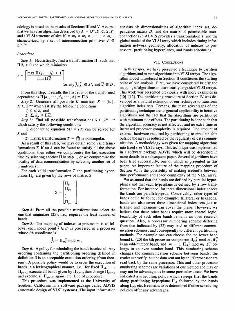
Lemma 2: The total number of bands in the index set is
r = n7I~ rmax H _k( J2) + 1] (25)k=1 mk
for any]',j2eJn.Proof: The term max Hpk(j' - J2) for any j1,2 EJ
represents the maximum number of index points along hyper-plane Hpk. The ratio between this term and the number ofprocessors available along the direction k, namely ink, is thenumber of partitions along direction k. The total number ofbands is then the cartesian product of the partitions along alln - 1 directions. Q.E.D.Thus Sp should be selected such that r in (25) is minimized
subject to
Hpkdi > 0 for any di E D,k = 1,2, n,n-1. (26)
By minimizing the number of bands we also minimizetime. Condition (26) means that if a band B, follows a bandB0, then no computation in Bo depends on data from a com-putation in B,. The minimization problem described above isfar too complex to be solved in a general case. However, wewill see later that by considering the data communicationrequirements, the space of feasible solutions and the com-plexity of selecting Sp are greatly reduced.
E. Selection ofSpfor Efficient Communication
A major concern in partitioning VLSI algorithms is tomake sure that data communication can be done efficiently.There are two aspects to consider; first, is the data commu-nication within each band, and second, is the data commu-nication between bands.
Consider]',]2 E Bi, withdi = 72 - Jl. According to ourprocessor allocation policy, di is mapped into the processorspace as follows:
dki = (Ipk 7) mod mk - (Ipk7) mod mk= Hpk7 - lpk J7= Hpkdi
fork = 1,2,9 ,n - 1 and i = 1,2,- ,r (27)
The effect of partitioning the index set in bands can be ex-pressed as a transformation of the original dependence ma-trix. The transformation function consists of fH and Sp ={IHp1, ...* H1p(n-1)}. Thus, the communication requirementsfor the partitioned case remain the same as for the trans-formed nonpartitioned case. The selection of S will be doneaccording to (9)-(1 1). These conditions guarantee that com-putations performed in the same band use only inter-connection primitives P.
Next, we describe how communications between com-putations in different bands are performed. Notice that anycomputation indexed by j such that (lpkI) mod Mk - 0 or(HlpkJ)modmk =mk - 1 for k = {1, ,n - 1}is exe-cuted by a peripheric processor. Such processors are used toperform INPUT/OUTPUT operations. Our communicationscheme uses processors for which (HpkJ) mod m, = mk - 1as output processors and those for which (Hpk I) mod mk = 0
as input processors. In other words, computations performedat points along the upper boundary hyperplanes of a givenband are allocated to output processors, and computationsperformed at points along lower boundary hyperplanes areallocated to input processors. Communication is done viaexternal memory, for instance a FIFO register.The important fact is that using our scheme of commu-
nication, minimum external hardware control is required.This is due to the regular external data flow, namely, data areoutput in the same order as they are input.
F. Numerical Stability ofPartitioned an Algorithm
We now show that the partitioning method described in thispaper does not affect in any way the accuracy of an algo-rithm. The theorem below simply indicates that the de-pendencies of an algorithm are not violated by any orderingimposed by our partitioning scheme.We need to express formally the execution ordering im-
plied by our partitioning technique.Definition 5: A partitioning ordering, denoted as >p, is
such that for any algorithm A = (Jf, C,D, X, Y) and 11, andany Sp {Hlpl ... , HP(nf1j)}, two points 1 j2 E J'n arerelated J2 >, if and only if either of the two followingconditions hold.
HI(] 2) > HI(J 1) and LHfpk (J)/mki = LHrpk l()/mki(28)
LnPk (J2)/mkI > LHIpk (7)/mMki for k = {1, ,n - 1}.(29)
The meaning of (28) is that j' and 72 belong to the samepartitioning band and computations are sequenced by timehyperplanes Hl; and (29) indicates that j1 and 72 belong todifferent bands and have a precedence relation that is inde-pendent of the time hyperplanes HI to which each belongs.
Theorem: For an algorithm A = (Jn, C, D, X, Y) the par-titioning ordering >z is an execution ordering.
Proof: By definition of execution ordering, it is enoughto prove that > 0,> Twocases must be considered:
Case 1: j and 2 belong to the same band, thus implyingthat
lHlpk (j0/mkJ = LIpk (j2)/mki k = 1, *,n - 1
From (7) I (di) = H(2) - H(J1) > 0. Then H( 2) >HI(] ') and by definition of >p,]2 >zP1. Hence, di >p 0.
Case 2: j1 and 2 belong to distinct bands, thus implyingthat
LHpk (J )/mkJ :$ LI l(J2)/mkj k = 1,* n - 1
Then using (26), Ipk(j2)/Mk > Hpk( l)/mMk Hence, by defi-nition of >p,,2 > P,i i.e., d, >p 0. Q.E.D.
VI. METHODOLOGY FOR PARTITIONING AND MAPPINGALGORITHMS INTO FIXED SIZED VLSI ARCHITECTURES
In this section, we propose a procedure for partitioning andmapping algorithms into fixed size VLSI arrays. This meth-
10
MOLDOVAN AND FORTES: PARTITIONING AND MAPPING ALGORITHMS INTO SYSTOLIC ARRAYS
odology is based on the results of Sections III and V. Assumethat we have an algorithm described by A = (Jf, D, C, X, Y)andaVLSIstructureofsizeM = ml X M2 X ,', x Mn-Icharacterized by a set of interconnection primitives P Ez (n- l)xs
Procedure
Step 1: Heuristically, find a transformation Hl, such thatHldi > 0 and which minimizes
=FmaxHfl -12)+ 1minIId
for any E,12CJn, and di E D.
From this step,_it results the first row of the transformeddependencies Hl [d1,...., di, * *, d] = HD.
Step 2: Generate all possible K matrices K = [kji],K C Zsxm which satisfy the following conditions:
1) 0 < kii and2) j kji di.
Step 3: Find all possible transformations S C Z(n-l)xnwhich satisfy the following conditions:
1) diophantine equation SD = PK can be solved forS and
2) matrix transformation T = [I] is nonsingular.As a result of this step, we may obtain some valid trans-
formations T. If no S can be found to satisfy all the aboveconditions, then either we compromise the fast executiontime by selecting another H in step 1, or we compromise thelocality of data communication by selecting another set ofprimitives P.
For each valid transformation T the partitioning hyper-planes fpi are given by the rows of matrix S
LiplHp2
LHp(n-1).J
Step 4: From all the possible transformations select theone that minimizes (25), i.e., requires the least number ofbands.
Step 5: The mapping of indexes to processors is as fol-lows: each index point j C Bi is processed in a processorwhose ith coordinate is
i= HIpj mod mi.
Step 6: A policy for scheduling the bands is selected. Anyordering containing the partitioning ordering defined indefinition 5 is an acceptable execution ordering (from theo-rem). A possible policy would be to order the execution ofbands in a lexicographical manner, i.e., for fixed flpi, * * ,
Hlp(n2) execute all bands given by Hp(n-l) then change Fp(n-2)and execute all Hp(n-l) again, etc. End of procedure.
This procedure was implemented at the University ofSouthern California in a software package called ADVIS(automatic design of VLSI systems). The input information
consists of: dimensionalities of algorithm index set, de-pendence matrix D, and the matrix of permissible inter-connections P. ADVIS provides a transformation T and theglobal model of the VLSI array which includes timing infor-mation network geometry, allocation of indexes to pro-cessors, partitioning hyperplanes, and bands scheduling.
VII. CONCLUSIONS
In this paper, we have presented a technique to partitionalgorithms and to map algorithms into VLSI arrays. The algo-rithm model introduced in Section II constitutes the startingpoint of our analysis. First, we have considered briefly themapping of algorithms into arbitrarily large size VLSI arrays.This work was presented previously with more examples in[10]-[12]. The partitioning procedure of Section IV was de-veloped as a natural extension of our technique to transformalgorithm index sets. Perhaps, the main advantages of thepartitioning technique are its general applicability to iterativealgorithms and the fact that the algorithms are partitionedwith minimum side effects. The partitioning is done such thatthe algorithm accuracy is not affected, and no extra time orincreased processor complexity is required. The amount ofexternal hardware required by partitioning to circulate dataoutside the array is reduced by the regularity of data commu-nication. A methodology was given for mapping algorithmsinto fixed size VLSI arrays. This technique was implementedin a software package ADVIS which will be described inmore details in a subsequent paper. Several algorithms havebeen tried successfully, one of which is presented in thispaper. An important feature of the mapping procedure ofSection VI is the possibility of making tradeoffs betweentime performance and space complexity of the VLSI array.We assumed that the bands are defined by parallel hyper-
planes and that each hyperplane is defined by a row trans-formation. For instance, for three-dimensional index spacesthe bands are parallelepipeds. Conceivably, other types ofbands could be found; for example, trilateral or hexagonalbands can also cover three-dimensional index sets just astriangle and hexagons can cover the plane. However, webelieve that these other bands require more control logic.Feasibility of such other bands remains an open researchquestion. Also, a processor numbering scheme differingfrom that indicated by (22) may lead to different commu-nication schemes, and consequently to different partitioningmethods. For example one can choose for the lower bandbound L, (20) the kth processor component HpkJ mod Mk if]is an odd-number band, and (m - 1) Hpkj mod Mk if] be-longs to an even-number band. This numbering schemechanges the communication scheme between bands; thereader can verify that the data sent out by an I/O processor areread back by the same processor. This and other processornumbering schemes are variations of our method and may ormay not be advantageous in some particular cases. We haveindicated a scheduling policy which sweeps first the bandsalong partitioninog hyperplaneHqIT followed by the bandsalong Hp2, etc. It remains to be determined if other schedulingpolicies offer any advantages.
11

IEEE TRANSACTIONS ON COMPUTERS, VOL. c-35, NO. 1, JANUARY 1986
VIII. NOTATION
J" is the nth-dimensional set of an algorithm.7i is the ith index point in the index set.io,Ji,J2 are the coordinates of an index point j; subscripts
indicate coordinates.j is an index point of the transformed algorithm without
partitioning. The notation ^ is consistent whenever we refer totransformed nonpartitioned algorithm.
J is an index point in the transformed algorithm with par-titioning. The notation * is consistent whenever we refer totransformed partitioned algorithm.
REFERENCES
[1] H. T. Kung, "Let's design algorithms for VLSI systems," in Proc. Cal-tech Conf. VLSI, Jan. 1979, pp. 65-90.
[2] H. T. Kung and C. E. Leiserson, "Systolic Arrays for VLSI," inIntroduc-tion to VLSI Systems, C. A. Mead and L. A. Conway. Reading, MA:Addison-Wesley, 1980, Sec. 8.3.
[3] S. Y. Kung et al., "Wavefront array processor: Language, architecture,and applications," IEEE Trans. Comput., vol. C-31, pp. 1054-1066,Nov. 1982.
[4] R. M. Karp, R. E. Miller, and S. Winograd, "The organization of com-putations for uniform recurrence equations," J. Ass. Comput. Mach.,vol. 14, pp. 563-590, July 1967.
[5] K. Hwang and Y. H. Chung, "Partitioned algorithms and VLSI structuresfor large-scale matrix computations," in Proc. 5th Symp. Comput. Arith-metic, May 1981, pp. 222-232.
[6] L. Johnnson, "Computational arrays for band matrix equations," Dep.Comput. Sci., California Inst. Technol., Pasadena, Tech. Rep. 4287,May 1981.
[7] -, "A computational array for the QR-method," in Proc. M.I.T. Conf.AdvancedResearch VLSI, Jan. 1982, pp. 123-129.
[8] D. Heller, "Partitioning big matrices for small systolic arrays," Dep.Comput. Sci., Pennsylvania State Univ., University Park, Rep. CS-83-02, Feb. 1983.
[9] M. A. Franklin et al., "Pin limitations and partitioning of VLSI intercon-nection networks," IEEE Trans. Comput., vol. C-31, pp. 1109-1116,Nov. 1981.
[10] J. A. B. Fortes and D. I. Moldovan, "Parallelism detection and algorithmtransformation techniques useful for VLSI architecture design," J. Paral-lel Distrib. Comput., May 1985; Dep. Elec. Eng.-Syst., Univ. SouthernCalifornia, Los Angeles, CA, Tech. Rep. PPP 83-1.
[11] D. I. Moldovan, "On the analysis and synthesis of VLSI algorithms,"IEEE Trans. Comput., vol. C-31, pp. 1121-1126, Nov. 1982.
[12] -, "On the design of algorithms for VLSI systolic arrays," Proc.IEEE, vol. 71, pp. 113-120, Jan. 1983.
Dan I. Moldovan (S'76-M'78) was born in Sibiu,Romania. In 1969, he received the Diplome Engi-neer degree in electrical engineering from Polytech-nical Institute of Bucharest, Bucharest, Romania.He received the M.S. degree in 1974, and thePh.D. degree in 1978, both in electrical engineeringand computer science from Columbia University,New York.
Between 1976 and 1979, he was a member of theTechical Staff at Bell Laboratories, Holmdel, NJ.From 1979 to 1981, he was an Assistant Professor at
Colorado State University, Fort Collins. He joined the Department of ElectricalEngineering-Systems at the University of Southern California, Los Angeles,in 1981. He is engaged in research in parallel processing focusing on mappingalgorithms into parallel computers, parallel symbolic processing, and parallelarchitectures for artificial intelligence.
Jose A.B. Fortes (S'80-M'84) was born in Lu-anda, Angola, on August 25, 1954. He received the
_ '~ Licenciatura em Engenharia Electrotecnica degreefrom the Universidade de Angola in 1978, the M.S.
_ degree in electrical engineering from the ColoradoState University, Fort Collins, in 1981, and the
_Ph.D. degree in electrical engineering from the Uni-versity of Southern California, Los Angeles, in1983.
Since 1984 he has been an Assistant Professor inthe School of Electrical Engineering, Purdue Uni-
versity, West Lafayette, IN. His research interests include architectures, lan-guages and algorithms for parallel processing, fault-tolerant computing, anddesign automation.
Dr. Fortes is a member of the Association for Computing Machinery.
12