Embed Size (px)
Citation preview

Volatile Particle Remover Calibration and Validation Procedures
Report to the Department for Transport Restricted Commercial ED47382004/VPR Issue Number 5 December 2007


Restricted – Commercial VPR Calibration Procedure AEA/ED47382/Issue 5
AEA Energy & Environment iii
Title Volatile Particle Remover Calibration and Validation Procedures
Customer Department for Transport Customer reference Contract No. PRO 4/9/4 Confidentiality, copyright and reproduction
This report is the Copyright of Department of Transport and has been prepared by AEA Technology plc under contract to Department for Transport dated 7 August 2006. The contents of this report may not be reproduced in whole or in part, nor passed to any organisation or person without the specific prior written permission of Department for Transport. AEA Technology plc accepts no liability whatsoever to any third party for any loss or damage arising from any interpretation or use of the information contained in this report, or reliance on any views expressed therein
File reference Willow\aug\emma\VPR Calibration Procedure Issue 5.doc Reference number ED47382004/VPR AEA Energy & Environment
Building 551.11 Harwell International Business Centre Didcot OX11 0QJ t: 0870 190 6566 f: 0870 190 6608 AEA Energy & Environment is a business name of AEA Technology plc AEA Energy & Environment is certificated to ISO9001
and ISO14001 Author Name Emma Sandbach Approved by Name Ian Marshall Signature Date 19 December 2007

VPR Calibration Procedure Restricted – Commercial AEA/ED47382/Issue 5
iv AEA Energy & Environment

Restricted – Commercial VPR Calibration Procedure AEA/ED47382/Issue 5
AEA Energy & Environment v
Table of contents
1 Introduction 1
2 VPR Overview 2 2.1 Requirements 2 2.2 Recommended System 2
3 Primary Calibration Methods 5 3.1 Primary Calibration Criteria 5 3.2 Calibration Aerosol 6 3.3 Additional equipment requirements 7
4 Validation Methods 9 4.1 Validation Method Criteria 9
5 Primary Calibration Procedures 11 5.1 Particle concentration reduction factor (fr) 11 5.2 Validation of the VPR for volatile particle removal efficiency 14 5.3 Calculation of particle concentration reduction factor (fr) 17 5.4 Calculation of removal efficiency of volatile particles 18
6 Validation Procedures 20 6.1 Particle concentration reduction factor (fr) 20 6.2 Validation of the VPR for volatile particle removal efficiency 22 6.3 Optional quality control check using gas dilution 26 6.4 Calculation of particle concentration reduction factor (fr) 27 6.5 Calculation of removal efficiency of volatile particles 27 6.6 Calculation of the quality control check gas concentration reduction factors 28
7 References 30
8 Annex 1: example of primary calibration of VPR 31
9 Annex 2: Example of particle concentration reduction factors (fr) 37
10 Glossary of Terms 39

VPR Calibration Procedure Restricted – Commercial AEA/ED47382/Issue 5
vi AEA Energy & Environment

Restricted – Commercial VPR Calibration Procedure AEA/ED47382/Issue 5
AEA Energy & Environment 1
1 Introduction Appendix 5 of the ‘Proposal for draft supplement 7 to the 05 series of amendments to Regulation
No.83’1 describes a sampling pre-conditioning system to be used for particle number emission
measurements of emissions after a cold start for type approval testing.
The sampling pre-conditioning unit as described is capable of diluting the sample in one or more
stages to achieve a particle number concentration below the threshold of the single particle count
mode of the particle number counter and to achieve a gas temperature below 35°C at the particle
number counter. The major component of the sample pre-conditioning system is a Volatile Particle
Remover (VPR), which is used to define the nature of the particles to be measured. The version of
the VPR described in the recommended system provides heated dilution, thermal conditioning of the
sample aerosol, further dilution of particle number concentration and cooling of the sample prior to
entry into the particle number counter.
This document describes the calibration and validation procedures for the VPR. Calibration of the
VPR is to be performed at the point of manufacture and validation is to be performed at least at 6
month intervals for all instruments without automatic temperature sensors or at least at 12 month
intervals if automatic temperature sensors are present. The calibration procedure must be repeated if
the system ‘fails’ its validation procedure or the particle number measurement system is modified in
any way.

VPR Calibration Procedure Restricted – Commercial AEA/ED47382/Issue 5
2 AEA Energy & Environment
2 VPR Overview
2.1 Requirements The specific requirements for the sample preconditioning unit are described in Appendix 5, Section 1.3
of ‘Proposal for draft supplement 7 to the 05 series of amendments to Regulation No.83’1.
Note: bold text highlights the most recent changes (Oct 07) to this Appendix.
1.3.1. The particle sample shall not pass through a pump before passing through the PNC.
1.3.2. A sample pre-classifier is recommended.
1.3.3. The sample preconditioning unit shall:
1.3.3.1. Be capable of diluting the sample in one or more stages to achieve a particle number
concentration below the upper threshold of the single particle count mode of the
PNC and a gas temperature below 35 °C at the inlet to the PNC.
1.3.3.2. Include an initial heated dilution stage which outputs a sample at a temperature of
≥150°C and ≤400°C and dilutes by a factor of at least 10.
1.3.3.3. Achieve a particle concentration reduction factor ( fr(di) ), as defined in section
2.2.2, for particles of 30 nma and 50 nm electrical mobility diameters, that is no more than 30 % and 20 % respectively higher, and no more than 5 % lower than
that for particles of 100 nm electrical mobility diameter for the VPR as a whole.
1.3.3.4. Also achieve >99.0 % vaporisation of 30 nm tetracontane (CH3(CH2)38CH3)
particles, with an inlet concentration of >10,000 cm-3, by means of heating and reduction of partial pressures of the tetracontane.
2.2 Recommended System The following section describes the recommended practice for particle number measurement, taken
from Section 1.4, Appendix 5 of the ‘Proposal for draft supplement 7 to the 05 series of amendments
to Regulation No.83’1. However, any sample preconditioning system meeting the requirements
detailed in Section 2.1 may be used. The recommended system is illustrated in Figure 1.
a All particle diameters referred to in this document are electrical mobility diameters.

Restricted – Commercial VPR Calibration Procedure AEA/ED47382/Issue 5
AEA Energy & Environment 3
1.4.4. Volatile Particle Remover
The VPR shall comprise one particle number diluter (PND1), an evaporation tube and a second diluter (PND2) in series. This dilution function is to reduce the number concentration of the sample entering the particle concentration measurement unit to less than the upper threshold of the single particle count mode of the PNC and to suppress nucleation within the sample.
The VPR shall achieve >99.0 % vaporisation of 30 nm tetracontane (CH3(CH2)38CH3) particles, with an inlet concentration of >10,000 cm-3, by means of heating and reduction of partial pressures of the tetracontane. It shall also achieve a particle concentration reduction factor (fr) for particles of 30 nm and 50 nm electrical mobility diameters, that is no more than 30 % and 20 % respectively higher, and no more than 5 % lower than that for particles of 100 nm electrical mobility diameter for the VPR as a whole.
1.4.4.1. First Particle Number Dilution Device (PND1)
The first particle number dilution device shall be specifically designed to dilute particle number concentration and operate at a (wall) temperature of 150°C - 400°C. The wall temperature setpoint should not exceed the wall temperature of the ET (paragraph 1.4.4.2.). The diluter should be supplied with HEPA filtered dilution air and be capable of a dilution factor of 10 to 200 times.
1.4.4.2. Evaporation Tube
The entire length of the ET shall be controlled to a wall temperature greater than or equal to that of the first particle number dilution device and the wall temperature held at a fixed value between 300 °C and 400 °C.
1.4.4.3. Second Particle Number Dilution Device (PND2)
PND2 shall be specifically designed to dilute particle number concentration. The diluter shall be supplied with HEPA filtered dilution air and be capable of maintaining a single dilution factor within a range of 10 to 30 times. The dilution factor of PND2 shall be selected in the range between 10 and 15 such that particle number concentration downstream of the second diluter is less than the upper threshold of the single particle count mode of the PNC and the gas temperature prior to entry to the PNC is <35°C.

VPR Calibration Procedure Restricted – Commercial AEA/ED47382/Issue 5
4 AEA Energy & Environment
Figure 1: Schematic of Recommended Particle Sampling System

Restricted – Commercial VPR Calibration Procedure AEA/ED47382/Issue 5
AEA Energy & Environment 5
3 Primary Calibration Methods The following general points are brought to the attention of the reader:
• Principles of good calibration practice should be adopted when using any of the methods
described below. In particular, users should ensure that any piece of ancillary equipment that
is critical to the calibration is itself appropriately calibrated before use.
• The calibration methods may rely upon comparing the measurements from two pieces of
aerosol measurement instrumentation. The user must ensure that the calibration aerosol
pathway to each instrument is configured so that any particle deposition that may occur
between particle source and instrument is comparable for both instruments. This is usually
achieved by ensuring residence time is comparable in both pathways whilst at the same time
ensuring pathways are as short as possible to minimise losses by agglomeration. A simple
method to ensure sample pathways have the same losses is to measure each sample line
using one PNC at a high aerosol concentration and check the measured concentration is the
same.
• Use of conductive tubing shall be required to minimise particle deposition.
• All calibrations shall be performed at room temperatures of ≤ 35°C.
• The term ‘upstream’ refers to the sampling location at the inlet of the VPR i.e. PND1 inlet.
• The term ‘downstream’ refers to the sampling location at the outlet of the VPR i.e. after the
second diluter PND2.
3.1 Primary Calibration Criteria Calibration of the VPR’s particle concentration reduction factors across its full range of dilution
settings, at the instrument manufacturer’s recommended operating temperatures, shall be required
when the unit is new and following any major maintenance. The periodic validation requirement for
the VPRs particle concentration reduction factor is limited to a check at a single setting, typical of that
used for measurement on diesel particulate filter equipped vehicles. The Technical Service shall
ensure the existence of a calibration or validation certificate for the volatile particle remover within a 6
month period prior to the emissions test. If the volatile particle remover incorporates temperature
monitoring alarms a 12 month validation interval shall be permissible.
Additionally, the Technical Service shall ensure the existence of a validation certificate for the VPR
demonstrating effective volatile particle removal efficiency within a 6 month period prior to the

VPR Calibration Procedure Restricted – Commercial AEA/ED47382/Issue 5
6 AEA Energy & Environment
emissions test. If the volatile particle remover incorporates temperature monitoring alarms a 12 month
validation interval shall be permissible.
3.1.1 Particle Concentration Reduction Factor (fr)
Calibration shall be undertaken by measuring the particle concentration reduction factor (fr) of solid
particles with an electrical mobility diameter of 30, 50 and 100 nm. For VPRs with a fixed dilution
factor the particle concentration reduction factor should be measured at the fixed setting. For VPRs
with a variable primary diluter (PND1) calibration shall be undertaken for at least 5 dilution factors
spaced logarithmically across the nominal dilution factor range. In the case of VPRs with a variable
secondary diluter (PND2) the calibration must be performed across a matrix of 15 nominal dilution
settings (the 5 settings at PND1 and 3 settings (10, 15 and an intermediate setting) at PND2). At each
nominal dilution setting it shall achieve a particle concentration reduction factor (fr) for particles of 30
nm and 50 nm electrical mobility diameters, that is no more than 30 % and 20 % respectively higher,
and no more than 5 % lower than that for particles of 100 nm electrical mobility diameter for the VPR
as a whole.
Calibration shall be conducted at the instrument manufacturer's recommended operating
temperatures.
3.1.2 Volatile Particle Removal Efficiency
The VPR shall achieve >99.0 % vaporisation of 30 nm tetracontane (CH3(CH2)38CH3) particles, with an
inlet concentration of >10,000 cm-3, by means of heating and reduction of partial pressures of the
tetracontane when operated at the following conditions:
• Manufacturer’s recommended evaporation tube temperature.
• VPRs with variable dilution factor settings: nominal secondary dilution factor of 10 (PND2), and
the lowest PND1 nominal dilution setting.
3.2 Calibration Aerosol
3.2.1 Solid particles
There are a number of aerosol generation techniquesthat are capable of producing solid particles in
the size range between 30 and 100 nm diameter including condensation generators, combustion
aerosol generators, nebulisation and hot wires. Some examples of these techniques are detailed in
References 3,4,6 and 7. This is not an exhaustive list and any of these methods are suitable for
producing calibration aerosols, but for the VPR calibration they must meet the following criteria:
• Capable of producing a stable aerosol at a minimum concentration of 5,000 particles cm-3 and
below the single particle count mode limit of the particle number counter.
• Monodispersity: GSD ≤ 1.2.

Restricted – Commercial VPR Calibration Procedure AEA/ED47382/Issue 5
AEA Energy & Environment 7
• Relative humidity <50 %.
• The aerosol generation technique and aerosol material must produce a solid aerosol that is
free from volatile particles.
Any calibration aerosol must be stable at VPR operating conditions, i.e. it should be physically and
chemically stable and its aerodynamic behaviour should not change at ET operating temperatures.
A common aerosol used for instrument calibration is sodium chloride. This is well characterised,
inexpensive and relatively safe to use compared with other materials. Sodium chloride particles may
be generated using a number of the techniques listed above.
3.2.2 Volatile particles
The requirements for volatile particles are more prescriptive than for solid particles, these are:
• Tetracontane (CH3(CH2)38CH3) particles with an electrical mobility diameter of at least 30 nm
at a concentration >10,000 particles cm-3.
• Monodispersity: GSD ≤ 1.2.
A condensation generator is a simple method to produce these particles. The monodispersity of the
aerosol (for both solid and volatile particles) should be verified if it is not defined by the aerosol
generator itself. A technique for producing solid and volatile particles is described in the example of
Annex 1. Alternative methods that generate similarly sized particles and concentrations are equally
appropriate.
3.3 Additional equipment requirements
The following table details the equipment, along with their purposes, that are additional to the
components of the particle number measurement system and are recommended for successful
calibration of the volatile particle remover (Table 1).

VPR Calibration Procedure Restricted – Commercial AEA/ED47382/Issue 5
8 AEA Energy & Environment
Table 1: Description of equipment required for calibration of the VPR
Required equipment Purpose
1 calibrated flow meter Measurement of particle counter flow
1 HEPA filter (class H13 of EN 1822:1998 or
better filtration efficiency) Zero checks on PNC and VPR
Aerosol generator(s) To generate solid and volatile particles for VPR
performance checks
1 neutraliser Neutralisation of charges on aerosol for
calibration
Calibrated Electrostatic Classifier/Scanning
Mobility Particle Sizer
Production of monodisperse aerosols. Other
instruments may be used to produce
monodisperse particles but an SMPS may be
required to verify the GSD.
Optional
Additional calibrated PNC
For simultaneous measurements of upstream and
downstream particle number concentration for
VPR performance checks.
Calibrated flow meter and pump
To simulate downstream PNC flow from VPR
whilst taking upstream measurements if
calibrating the VPR with one PNC.

Restricted – Commercial VPR Calibration Procedure AEA/ED47382/Issue 5
AEA Energy & Environment 9
4 Validation Methods The following general points are brought to the attention of the reader:
• Principles of good calibration practice should be adopted when using any of the methods
described below. In particular, users should ensure that any piece of ancillary equipment that
is critical to the validation is appropriately calibrated before use.
• The validation methods may rely upon comparing the measurements from two pieces of
aerosol measurement instrumentation. The user must ensure that the calibration aerosol
pathway to each instrument is configured so that any particle deposition that may occur
between particle source and instrument is comparable for both instruments. This is usually
achieved by ensuring residence time is comparable in both pathways whilst at the same time
ensuring pathways are as short as possible to minimise losses by agglomeration. A simple
method to ensure sample pathways have the same losses is to measure each sample line
using one PNC at a high aerosol concentration and check the measured concentration is the
same.
• Use of conductive tubing shall be required to minimise particle deposition.
• All calibrations shall be performed at room temperatures of ≤ 35°C.
• The term ‘upstream’ refers to the sampling location at the inlet of the VPR i.e. PND1 inlet.
• The term ‘downstream’ refers to the sampling location at the outlet of the VPR i.e. after the
second diluter PND2.
4.1 Validation Method Criteria The VPR must be validated in terms of its particle concentration reduction factor (fr) and its volatile
particle removal efficiency (or suppression of nucleation particles).
The Technical Service shall ensure the existence of a validation certificate of the volatile particle
remover within a 6-month period prior to the emissions test. If the volatile particle remover
incorporates temperature monitoring alarms a 12-month validation interval shall be permissible.
The validation aerosol and equipment requirements are identical to those described for primary
calibration in Sections 3.2 and 3.3.

VPR Calibration Procedure Restricted – Commercial AEA/ED47382/Issue 5
10 AEA Energy & Environment
An additional, optional quality control check of VPR performance may also be performed more
frequently, as required, through measurement of the dilution factors using gas. Table 2 describes the
additional required equipment if this optional check is adopted.
Table 2: Required equipment for optional quality control check with gas dilution
Required equipment Purpose
1 calibrated gas analyser (recommended CO,
CO2 or NOx analyser with converter) Calibration of the diluters
1 bottle of certified gas (recommended ≥ 50,000
ppm CO, CO2, N2, propane or NO, uncertainty on
certified concentration better than 2%)
Calibration of the diluters
1 calibrated flow meter/rotameter To indicate inlet flow of gas supply to diluter to
ensure ambient pressure at diluter inlet.
4.1.1 Particle Concentration Reduction Factor (fr)
Validation shall be undertaken by measuring the particle concentration reduction factor (fr) of solid
particles with an electrical mobility diameter of 30, 50 and 100 nm. For VPRs with variable dilution
factor settings validation shall be undertaken at one dilution setting typical for DPF exhaust emissions
measurement and at the manufacturer’s recommended operating temperatures.
The validation acceptance criterion is that the validation measurement is ±10 % of the particle
concentration reduction factor (fr) as determined during the primary calibration.
4.1.2 Volatile Particle Removal Efficiency
The VPR shall achieve >99.0 % vaporisation of 30 nm tetracontane (CH3(CH2)38CH3) particles, with an
inlet concentration of >10,000 cm-3, by means of heating and reduction of partial pressures of the
tetracontane when operated at the following conditions:
• Manufacturer’s recommended evaporation tube temperature.
• VPRs with variable dilution factor settings: nominal secondary dilution factor of 10 (PND2), and
the lowest PND1 nominal dilution setting.
Restricted – Commercial VPR Calibration Procedure AEA/ED47382/Issue 5
AEA Energy & Environment 11
5 Primary Calibration Procedures The procedures for performing a VPR calibration are described below. For all calibration and
validation procedures a stable aerosol is defined as having an upstream concentration drift of less
than 10 % over a 5 minute period.
5.1 Particle concentration reduction factor (fr) The particle concentration reduction factor (fr) may be measured in two ways:
1. Using one particle counter. In this case the upstream and downstream particle number
concentrations are recorded using the same PNC sampling at either position through
equivalent sampling lines. Upstream and downstream sampling lines are simply exchanged
and the number concentration allowed to stabilise before measurement commences. Finally,
the upstream sampling line should be reconnected to the PNC to verify that the upstream
concentration has not drifted (by more than 10 %) during the measurement.
2. Using two particle counters, one measuring upstream/at the VPR inlet and one measuring
downstream/at the VPR outlet. If this option is selected then it is assumed that the correlation
between the two PNCs (at the inlet and outlet of the VPR), has been confirmed before this
procedure commences using the secondary calibration method described in the
‘Condensation Particle Counter Calibration Procedures5’ document. The PNCs’ response at
all particle diameters (30, 50 and 100 nm) must be measured. Readings from one PNC must
be adjusted to take into consideration any differences between the two instruments. If two
different models of PNCs are used, their counting efficiency may differ significantly for 30 nm
diameter particles. Additionally the data from the upstream and downstream PNCs must be
time aligned to account for the VPR residence time.
Prepare the VPR and PNCs for use:
a. Position all apparatus according to the manufacturers instructions, this will be generally similar
to that described in the example, Annex 1, Figure 2.
b. Where appropriate clean any dilution mechanisms within the VPR as advised by the
manufacturer (e.g. for rotating disc diluters remove the disc and clean using an appropriate
solvent).
c. Perform any routine maintenance of the VPR as advised by the manufacturer (e.g. replacement
of filters, tubing etc.).
d. Switch on the electrostatic classifier (or other source of monodisperse particles), PNCs and
VPR.
e. Fill the PNCs with working fluid and allow the saturator and condenser to reach their specified
temperatures.
f. Apply an external vacuum source to the PNCs if not fitted with an internal pump.
g. Do not proceed unless all indicators on the PNCs show correct instrument status (e.g.
temperature, liquid level, flow and laser etc.).

VPR Calibration Procedure Restricted – Commercial AEA/ED47382/Issue 5
12 AEA Energy & Environment
h. Check the inlet flow rates of the PNCs with an appropriate calibrated flow meter (low pressure
drop variety recommended, e.g. bubble flow meter). The flow into the particle counter shall
report a measured value within 5 percent of the particle counter nominal flow rate.
i. Check that zero concentration is reported when a HEPA filter (class H13 of EN 1822:1998 or
better filtration efficiency) is attached to the inlet of the PNCs. The PNC requires attention from
the manufacturer if concentrations greater than 0.2 particles cm-3 are reported.
j. If required, apply clean dry filtered air to the VPR at pressures specified by the manufacturer.
k. Switch on heating to VPR and allow to reach specified temperatures.
l. Connect the PNC to the VPR.
m. When the VPR has reached its specified temperature settings connect a HEPA filter (class H13
of EN 1822:1998 or better filtration efficiency) to the inlet and ensure a zero concentration is
reported on the PNC. Do not proceed if particle concentrations greater than 0.5 particles cm-3
are reported.
n. If the “one PNC” method is being used for the calibration exchange the sampling line from the
VPR outlet location (downstream) to the VPR inlet (upstream) and use a mass flow controller, or
similar, to simulate the flow rate of the PNC from the VPR. If the “two PNC” method is used
split the flow from the neutraliser between the upstream PNC and the inlet of the VPR.
Note: if an aerosol generator that produces monodisperse particles is used, the electrostatic classifier
is not required and the VPR can be connected directly to the aerosol source via a neutraliser.
o. Ensure that the particle residence time in the pipework from the neutraliser to both the upstream
PNC and the inlet to the VPR are identical. Residence time must be adjusted by varying the
length rather than the diameter of the pathway, as diffusional deposition is independent of tube
diameter for a given volumetric flow rate.
p. Set the electrostatic classifier flows such that the monodisperse aerosol flow leaving the
classifier is sufficient for the total inlet flow of both the PNC and the VPR (provide additional
particle-free flow after the classifier if necessary, ensuring an adequate mixing length for the
aerosol and particle-free air before the inlet of the PNC and VPR).
Make arrangements to log data from both the upstream (inlet) and downstream (outlet) PNCs
simultaneously at the same sampling rate.
Generate the calibration aerosol and connect the electrostatic classifier to the source.
q. For variable primary diluters select a nominal dilution setting on PND1.
For VPRs with fixed dilution factors skip to step (s).
r. For variable PND2 diluters select a nominal dilution setting on PND2.
s. Select a monodisperse diameter (30, 50 or 100 nm) using the electrostatic classifier and allow
the number concentration to stabilise upstream of the VPR. All monodisperse particles must
enter the VPR at concentrations of greater than 5,000 particles cm-3. Once stable record

Restricted – Commercial VPR Calibration Procedure AEA/ED47382/Issue 5
AEA Energy & Environment 13
measurements for 1 minute (or the time required for a cumulative number count of 10,000
particles, whichever is greater) up and downstream of the VPR
t. For VPRs with fixed dilution factors skip to step (x).
For VPRs with variable dilution factors: Once a stable measurement has been taken select the
next nominal dilution setting on PND1, allow to stabilise and record measurements for 1 minute
(or the time required for a cumulative number count of 10,000 particles, whichever is greater) up
and downstream of the VPR.
u. Repeat step (t) until all five dilution settings of PND1 have been measured.
v. For variable PND2 diluters, select the next nominal dilution setting, and repeat the
measurements for all five dilution settings on PND1.
w. Select the third and final nominal dilution setting on PND2 and repeat the measurements for all
five dilution settings on PND1.
Note: The minimum number of measurement conditions per particle diameter should be 15 for a
variable secondary diluter, for a fixed secondary diluter the minimum number of measurement
conditions should be five per particle diameter. For VPRs with fixed primary and secondary dilution
factors only 1 measurement is required at each particle diameter.
x. The next monodisperse diameter should be selected on the electrostatic classifier and allowed
to stabilise. Repeat steps (s) to (w) for each monodisperse diameter.
y. If the “one PNC” method is used each measurement must be stable and the upstream
measurement must be verified after measuring the downstream concentration to ensure the
inlet concentration has not drifted during the measurement, e.g. measure upstream
concentration for 1 minute, measure the downstream concentration for 1 minute, then return to
the upstream sampling arrangement and sample for 1 minute to ensure the concentration is
stable (or the time required for a cumulative number count of 10,000 particles, whichever is
greater). Measurement is valid if upstream particle concentration is within ±10 % of initial
reading.
Note: Sample times must be sufficient to ensure a minimum of 10,000 particles are counted at each
measurement condition (cumulatively over the sample period).
Once all required diameters and nominal dilution settings have been measured the aerosol source
should be disconnected from the VPR and a HEPA filter (class H13 of EN 1822:1998 or better filtration
efficiency) applied to the inlet to remove all particles from the system and to verify the zero
concentration leaving the VPR (should be less than 0.5 particle cm-3). This ensures the VPR has not
become contaminated from the calibration procedure.

VPR Calibration Procedure Restricted – Commercial AEA/ED47382/Issue 5
14 AEA Energy & Environment
5.2 Validation of the VPR for volatile particle removal efficiency
For this validation only one monodisperse diameter is required; tetracontane particles
(CH3(CH2)38CH3) of electrical mobility diameter of at least 30 nm at an inlet concentration of ≥ 10,000
particles cm-3.
VPRs with variable dilution settings should be validated at one nominal dilution setting, with PND1 at
the lowest setting and for variable PND2 diluters a nominal dilution setting of 10 should be used. The
evaporation tube should be at the operating conditions recommended by the manufacturer (and that
most commonly used for DPF exhaust emissions measurements).
There are two methods for measurement of volatile particle removal efficiency:
Method 1 - Measurement of up and downstream particle concentrations using a PNC
This can be the PNC supplied with the particle number measurement system. For the volatile particle
removal efficiency calibration an upstream concentration of ≥ 10,000 particles cm-3 is required,
however this concentration may be above the full-scale deflection of the PNC in single particle count
mode. An assumption can be made that any measurement by the PNC above this limit ensures the
VPR is challenged with a minimum of 10,000 particles cm-3. The procedure for this method is as
follows (this validation can be performed with either one or two PNCs, if two PNCs are used their
response at all particle diameters (30, 50 and 100 nm) must be compared using the secondary
calibration method described in the ‘Condensation Particle Counter Calibration Procedures5’
document. One PNC must be adjusted to take into consideration any differences between the two
instruments. If two different models of PNC are used their counting efficiency may differ significantly
for 30 nm diameter particles. Additionally the data from the upstream and downstream PNCs must be
time aligned to account for the VPR residence time):
Prepare the VPR and PNCs for use:
a. Position all apparatus according to the manufacturers instructions, this will be generally similar
to that described in the example, Annex 1, Figure 2.
b. Where appropriate clean any dilution mechanisms within the VPR as advised by the
manufacturer (e.g. for rotating disc diluters remove the disc and clean using an appropriate
solvent).
c. Perform any routine maintenance of the VPR as advised by the manufacturer (e.g. replacement
of filters, tubing etc.).
d. Switch on the electrostatic classifier (or other source of monodisperse particles), PNCs and
VPR.
e. Fill the PNCs with working fluid and allow the saturator and condenser to reach their specified
temperatures.
f. Apply an external vacuum source to the PNCs if not fitted with an internal pump.

Restricted – Commercial VPR Calibration Procedure AEA/ED47382/Issue 5
AEA Energy & Environment 15
g. Do not proceed unless all indicators on the PNCs show correct instrument status (e.g.
temperature, liquid level, flow and laser etc.).
h. Check the inlet flow rates of the PNCs with an appropriate calibrated flow meter (low pressure
drop variety recommended, e.g. bubble flow meter). The flow into the particle counter shall
report a measured value within 5 percent of the particle counter nominal flow rate.
i. Check that zero concentration is reported when a HEPA filter (class H13 of EN 1822:1998 or
better filtration efficiency) is attached to the inlet of the PNCs. The PNC requires attention from
the manufacturer if concentrations greater than 0.2 particles cm-3 are reported.
j. If required, apply clean dry filtered air to the VPR at pressures specified by the manufacturer.
k. Switch on heating to VPR and allow to reach specified temperatures.
l. Connect the PNC to the VPR.
m. When the VPR has reached its specified temperature settings connect a HEPA filter (class H13
of EN 1822:1998 or better filtration efficiency) to the inlet and ensure a zero concentration is
reported on the PNC. Do not proceed if particle concentrations greater than 0.5 particles cm-3
are reported.
n. If the “one PNC” method is used for the volatile particle calibration exchange the sampling line
from the VPR outlet location (downstream) to the VPR inlet (upstream) and use a mass flow
controller, or similar, to simulate the flow rate of the PNC from the VPR. If the “two PNC”
method is adopted split the flow from the neutraliser between the upstream PNC and the inlet of
the VPR.
Note: if an aerosol generator that produces monodisperse particles is used, the electrostatic classifier
is not required and the VPR can be connected directly to the aerosol source via a neutraliser.
o. Ensure that the particle residence time in the pipework from the neutraliser to both the upstream
PNC and the inlet to the VPR are identical. Residence time must be adjusted by varying the
length rather than the diameter of the pathway, as diffusional deposition is independent of tube
diameter for a given volumetric flow rate.
p. Set the electrostatic classifier flows such that the monodisperse aerosol flow leaving the
classifier is sufficient for the total inlet flow of both the PNC and the VPR (provide additional
particle-free flow after the classifier if necessary, ensuring an adequate mixing length for the
aerosol and particle-free air before the inlet of the PNC and VPR).
Make arrangements to log data from both the upstream (inlet) and downstream (outlet) PNCs
simultaneously at the same sampling rate.
Generate the validation aerosol and connect the electrostatic classifier to the source.
q. Select 30 nm diameter particles using the electrostatic classifier and allow the number
concentration to stabilise upstream of the VPR. Once stable record measurements for 1 minute
(or the time required for a cumulative number count of 10,000 particles, whichever is greater) up
and downstream of the VPR.

VPR Calibration Procedure Restricted – Commercial AEA/ED47382/Issue 5
16 AEA Energy & Environment
r. If the “one PNC” method is adopted each measurement must be stable and the upstream
measurement must be verified after measuring the downstream concentration to ensure the
inlet concentration has not drifted during the measurement, e.g. measure upstream
concentration for 1 minute, measure the downstream concentration for 1 minute, then return to
the upstream sampling arrangement and sample for 1 minute to ensure the concentration is
stable (or the time required for a cumulative number count of 10,000 particles, whichever is
greater). The drift of the upstream aerosol concentration must not be more than 10 %.
Once complete the aerosol source should be disconnected from the VPR and a HEPA filter (class H13
of EN 1822:1998 or better filtration efficiency) applied to the inlet to remove all particles from the
system and to verify the zero concentration leaving the VPR (should be less than 0.5 particle cm-3).
This ensures the VPR has not become contaminated from the validation procedure.
Method 2 - One PNC measuring downstream of the VPR only
The particle counter used for this method can be the PNC supplied with the particle number
measurement system. The procedure for this method is as follows:
Prepare the VPR and PNCs for use:
a. Position all apparatus according to the manufacturers instructions, this should be something
similar to that described in the example, Annex 1, Figure 2.
b. Where appropriate clean any dilution mechanisms within the VPR as advised by the
manufacturer (e.g. for rotating disc diluters remove the disc and clean using an appropriate
solvent).
c. Perform any routine maintenance of the VPR as advised by the manufacturer (e.g. replacement
of filters, tubing etc.).
d. Switch on the electrostatic classifier (or other source of monodisperse particles), PNC and VPR.
e. Fill the PNC with working fluid and allow the saturator and condenser to reach their specified
temperatures.
f. Apply an external vacuum source to the PNC if not fitted with an internal pump.
g. Do not proceed unless all indicators on the PNC show correct instrument status (e.g.
temperature, liquid level, flow and laser etc.).
h. Check the inlet flow rates of the PNC with an appropriate calibrated flow meter (low pressure
drop variety recommended, e.g. bubble flow meter). The flow into the particle counter shall
report a measured value within 5 percent of the particle counter nominal flow rate.
i. Check that zero concentration is reported when a HEPA filter (class H13 of EN 1822:1998 or
better filtration efficiency) is attached to the inlet of the PNC. The PNC requires attention from
the manufacturer if concentrations greater than 0.2 particles cm-3 are reported.
j. If required, apply clean dry filtered air to the VPR at pressures specified by the manufacturer.
k. Connect the PNC to the VPR.
l. Do not heat the VPR, leave it at room temperature (upper limit of 35°C).

Restricted – Commercial VPR Calibration Procedure AEA/ED47382/Issue 5
AEA Energy & Environment 17
m. Connect a HEPA filter (class H13 of EN 1822:1998 or better filtration efficiency) to the inlet of
the VPR and ensure a zero concentration is reported on the PNC. Do not proceed if particle
concentrations of greater than 0.5 particles cm-3 are reported.
Note: if an aerosol generator that produces monodisperse particles is used, the electrostatic classifier
is not required and the VPR can be connected directly to the aerosol source via a neutraliser.
n. Set the electrostatic classifier flows such that the monodisperse aerosol flow leaving the
classifier is sufficient for the inlet flow of the VPR (provide additional particle-free flow after the
classifier if necessary, ensuring an adequate mixing length for the aerosol and particle-free air
before the inlet of the PNC and VPR).
Make arrangements to log data from the PNC.
Generate the validation aerosol and connect the electrostatic classifier to the source.
o. Select 30 nm using the electrostatic classifier and allow to stabilise for at least 1 minute (or the
time required for a cumulative number count of 10,000 particles, whichever is greater). The
monodisperse particles must enter the VPR at concentrations of greater than 10,000
particles cm-3. Once stable record measurements for 1 minute downstream of the VPR (or the
time required for a cumulative number count of 10,000 particles, whichever is greater).
p. Switch on heating to VPR and allow to reach specified temperatures. Identical nominal dilution
settings should be used at both temperature settings.
q. Continue to supply 30 nm tetracontane particles to the VPR and record the particle
concentration from the PNC (at the downstream location).
r. When a stable downstream concentration is achieved, and the VPR has reached its
temperature settings, record the downstream number concentrations over a 1 minute period (or
the time required for a cumulative number count of 10,000 particles, whichever is greater).
Once complete the aerosol source should be disconnected from the VPR and a HEPA filter (class H13
of EN 1822:1998 or better filtration efficiency) applied to the inlet to remove all particles from the
system and to verify the zero concentration leaving the VPR (should be less than 0.5 particle cm-3).
This ensures the VPR has not become contaminated from the validation procedure.
5.3 Calculation of particle concentration reduction factor (fr)
For each nominal dilution setting and particle diameter the ratio of upstream number concentration to
downstream number concentration should be calculated:
The particle concentration reduction factor at each particle size (fr(di)) shall be calculated as follows;

VPR Calibration Procedure Restricted – Commercial AEA/ED47382/Issue 5
18 AEA Energy & Environment
)()(
)(iout
iinir dN
dNdf = (1)
Where Nin (di) = upstream particle number concentration for particles of diameter di;
Nout (di) = downstream particle number concentration for particles of diameter di; and di = particle electrical mobility diameter (30, 50 or 100 nm)
For each nominal dilution setting the mean particle concentration reduction factor ( rf ) should then be
calculated for all particle diameters;
3)100()50()30( nmfnmfnmff rrr
r++
= (2)
At each nominal dilution setting the VPR shall achieve a particle concentration reduction factor (fr) for
particles of 30 nm and 50 nm electrical mobility diameters, that is no more than 30 % and 20 %
respectively higher, and no more than 5 % lower than that for particles of 100 nm electrical mobility
diameter for the VPR as a whole:
95.0)100()30(3.1 >>
nmfnmf
r
r (3)
95.0)100()50(2.1 >>
nmfnmf
r
r (4)
For VPRs with variable primary diluter settings a minimum of five particle concentration reduction
factors (fr) corresponding to five nominal dilution settings are required. For VPRs with a variable
secondary diluter (PND2) fifteen particle concentration reduction factors (fr) will be produced (five
primary diluter settings at three secondary diluter settings). For VPRs with fixed dilution settings only
one particle concentration reduction factor will be produced.
Some examples of particle concentration reduction factors are shown in Table 5, Annex 2.
5.4 Calculation of removal efficiency of volatile particles There are two methods to calculate the removal efficiency of volatile particles depending on which
validation method was adopted:
5.4.1 Method 1
The average number concentration of volatile particles at the inlet of the VPR should be calculated
over the 1 minute stable period (or the time required for a cumulative number count of 10,000
particles, whichever is greater). The performance requirement of the VPR is that >99.0 % of
tetracontane particles are removed. Therefore the pass criterion for the suppression of nucleation
particles is 1 % of the inlet concentration.

Restricted – Commercial VPR Calibration Procedure AEA/ED47382/Issue 5
AEA Energy & Environment 19
The average number concentration at the outlet of the VPR should be calculated over the 1 minute
stable period (or the time required for a cumulative number count of 10,000 particles, whichever is
greater), and if this is less than 1 % of the inlet concentration then the VPR performance is acceptable.
A particle concentration reduction factor (fr) must be applied to the downstream number concentration
measurements. This factor is that calculated at 30 nm, for the same nominal dilution settings used in
the primary calibration with solid particles.
Volatile Particle Removal Efficiency Criteria:
100)30(. ionConcentratUpstreamAveragenmfionConcentratDownstreamAverage r ≤ (5)
where fr(30 nm) = particle concentration reduction factor at 30 nm and the same nominal dilution
settings.
5.4.2 Method 2
The average number concentration of volatile particles downstream of the VPR should be calculated
over the 1 minute stable period (or the time required for a cumulative number count of 10,000
particles, whichever is greater) for both temperature conditions i.e. room temperature and heated.
Volatile Particle Removal Efficiency Acceptance Criteria:
100)()( RTionConcentratDownstreamAverageHTionConcentratDownstreamAverage ≤ (6)
where RT = room temperature VPR
HT = heated VPR

VPR Calibration Procedure Restricted – Commercial AEA/ED47382/Issue 5
20 AEA Energy & Environment
6 Validation Procedures The procedures for performing a VPR validation are described below. For all procedures a stable
aerosol is defined as having an upstream concentration drift of less than 10 % over a 5 minute period.
6.1 Particle concentration reduction factor (fr) The particle concentration reduction factor (fr) may be measured in two ways:
1. Using one particle counter. In this case the upstream and downstream particle number
concentrations are recorded using the same PNC sampling at either position through
equivalent sampling lines. Upstream and downstream sampling lines are simply
exchanged and the number concentration allowed to stabilise before measurement
commences. Finally, the upstream sampling line should be reconnected to the PNC to
verify that the upstream concentration has not drifted by more than 10 % during the
measurement.
2. Using two particle counters, one measuring upstream/at the VPR inlet and one measuring
downstream/at the VPR outlet. If this option is selected then it is assumed that the
correlation between the two PNCs (at the inlet and outlet of the VPR), has been confirmed
before this procedure commences using the secondary calibration method described in
the ‘Condensation Particle Counter Calibration Procedures5’ document. The PNC’s
response at all particle diameters (30, 50 and 100 nm) must be measured. Readings from
one PNC must be adjusted to take into consideration any differences between the two
instruments. If using two different models of PNC, their counting efficiency may differ
significantly for 30 nm diameter particles. Additionally the data from the upstream and
downstream PNCs must be time aligned to account for the VPR residence time.
Prepare the VPR and PNCs for use:
a. Position all apparatus according to the manufacturers instructions, this will be generally similar
to that described in the example, Annex 1, Figure 2.
b. Where appropriate clean any dilution mechanisms within the VPR as advised by the
manufacturer (e.g. for rotating disc diluters remove the disc and clean using an appropriate
solvent).
c. Perform any routine maintenance of the VPR as advised by the manufacturer (e.g. replacement
of filters, tubing etc.).
d. Switch on the electrostatic classifier (or other source of monodisperse particles), PNCs and
VPR.
e. Fill the PNCs with working fluid and allow the saturator and condenser to reach their specified
temperatures.
f. Apply an external vacuum source to the PNCs if not fitted with an internal pump.

Restricted – Commercial VPR Calibration Procedure AEA/ED47382/Issue 5
AEA Energy & Environment 21
g. Do not proceed unless all indicators on the PNCs show correct instrument status (e.g.
temperature, liquid level, flow and laser etc.).
h. Check the inlet flow rates of the PNCs with an appropriate calibrated flow meter (low pressure
drop variety recommended, e.g. bubble flow meter). The flow into the particle counter shall
report a measured value within 5 percent of the particle counter nominal flow rate.
i. Check that zero concentration is reported when a HEPA filter (class H13 of EN 1822:1998 or
better filtration efficiency) is attached to the inlet of the PNCs. The PNC requires attention from
the manufacturer if concentrations greater than 0.2 particles cm-3 are reported.
j. If required, apply clean dry filtered air to the VPR at pressures specified by the manufacturer.
k. Switch on heating to VPR and allow to reach specified temperatures.
l. Connect the PNC to the VPR.
m. When the VPR has reached its specified temperature settings connect a HEPA filter (class H13
of EN 1822:1998 or better filtration efficiency) to the inlet and ensure a zero concentration is
reported on the PNC. Do not proceed if particle concentrations greater than 0.5 particles cm-3
are reported.
n. If the “one PNC” method is adopted for the validation exchange the sampling line from the VPR
outlet location (downstream) to the VPR inlet (upstream) and use a mass flow controller, or
similar, to simulate the flow rate of the PNC from the VPR. If the “two PNC” method is adopted
split the flow from the neutraliser between the upstream PNC and the inlet of the VPR.
Note: if an aerosol generator that produces monodisperse particles is used, the electrostatic classifier
is not required and the VPR can be connected directly to the aerosol source via a neutraliser.
o. Ensure that the particle residence time in the pipework from the neutraliser to both the upstream
PNC and the inlet to the VPR are identical. Residence time must be adjusted by varying the
length rather than the diameter of the pathway, as diffusional deposition is independent of tube
diameter for a given volumetric flow rate.
p. Set the electrostatic classifier flows such that the monodisperse aerosol flow leaving the
classifier is sufficient for the total inlet flow of both the PNC and the VPR (provide additional
particle-free flow after the classifier if necessary, ensuring an adequate mixing length for the
aerosol and particle-free air before the inlet of the PNC and VPR).
Make arrangements to log data from both the upstream (inlet) and downstream (outlet) PNCs
simultaneously at the same sampling rate.
q. Generate the validation aerosol and connect the electrostatic classifier to the source.
r. For VPRs with variable dilution settings select nominal dilution settings on PND1 and PND2
typically used for DPF exhaust emissions measurements.
s. Select a monodisperse diameter (30, 50 or 100 nm) using the electrostatic classifier and allow
the number concentration to stabilise upstream of the VPR. All monodisperse particles must
enter the VPR at concentrations of greater than 5000 particles cm-3. Once stable record

VPR Calibration Procedure Restricted – Commercial AEA/ED47382/Issue 5
22 AEA Energy & Environment
measurements for 1 minute (or the time required for a cumulative number count of 10,000
particles, whichever is greater) up and downstream of the VPR
t. The next monodisperse diameter should then be selected on the electrostatic classifier and
allowed to stabilise. Repeat step (s) for each monodisperse diameter.
u. If the “one PNC” method is adopted each measurement must be stable and the upstream
measurement must be verified after measuring the downstream concentration to ensure the
inlet concentration has not drifted during the measurement, e.g. measure upstream
concentration for 1 minute, measure the downstream concentration for 1 minute, then return to
the upstream sampling arrangement and sample for 1 minute to ensure the concentration is
stable (or the time required for a cumulative number count of 10,000 particles, whichever is
greater). Measurement is valid if upstream particle concentration is within ±10 % of initial
reading.
Once all required diameters have been measured the aerosol source should be disconnected from the
VPR and a HEPA filter (class H13 of EN 1822:1998 or better filtration efficiency) applied to the inlet to
remove all particles from the system and to verify the zero concentration leaving the VPR (should be
less than 0.5 particle cm-3). This ensures the VPR has not become contaminated from the calibration
procedure.
6.2 Validation of the VPR for volatile particle removal efficiency
This validation requires tetracontane (CH3(CH2)38CH3) particles of at least 30 nm electrical mobility
diameter at an inlet concentration at the VPR of ≥ 10,000 particles cm-3.
The VPR should be validated at one nominal dilution setting, PND1 should be at the lowest setting and
for variable PND2 diluters a nominal dilution setting of 10 should be used. The evaporation tube
should be at the operating conditions recommended by the manufacturer (and that most commonly
used for DPF exhaust emissions measurements).
There are two methods for measurement of volatile particle removal efficiency:
Method 1 - Measurement of up and downstream particle concentrations using a PNC
This can be the PNC supplied with the particle number measurement system. For the volatile particle
removal efficiency validation an upstream concentration of ≥ 10,000 particles cm-3 is required, however
this concentration will result in coincidence errors to be introduced into the PNC measurement. An
assumption can be made that any measurement by the PNC above this limit ensures the VPR is
challenged with a minimum of 10,000 particles cm-3. This validation can be performed with either one
or two PNCs. If two PNCs are used, their response at all particle diameters (30, 50 and 100 nm) must
be measured using the secondary calibration method described in the ‘Condensation Particle Counter
Calibration Procedures5’ document. One PNC must be adjusted to take into consideration any
Restricted – Commercial VPR Calibration Procedure AEA/ED47382/Issue 5
AEA Energy & Environment 23
differences between the two instruments. If two different models of PNC are used please note their
counting efficiency may differ significantly for 30 nm diameter particles. Additionally the data from the
upstream and downstream PNCs must be time aligned to account for the VPR residence time. The
procedure for this method is as follows.
Prepare the VPR and PNCs for use:
a. Position all apparatus according to the manufacturers instructions, this will be generally similar
to that described in the example, Annex 1, Figure 2.
b. Where appropriate clean any dilution mechanisms within the VPR as advised by the
manufacturer (e.g. for rotating disc diluters remove the disc and clean using an appropriate
solvent).
c. Perform any routine maintenance of the VPR as advised by the manufacturer (e.g. replacement
of filters, tubing etc.).
d. Switch on the electrostatic classifier (or other source of monodisperse particles), PNCs and
VPR.
e. Fill the PNCs with working fluid and allow the saturator and condenser to reach their specified
temperatures.
f. Apply an external vacuum source to the PNCs if not fitted with an internal pump.
g. Do not proceed unless all indicators on the PNCs show correct instrument status (e.g.
temperature, liquid level, flow and laser etc.).
h. Check the inlet flow rates of the PNCs with an appropriate calibrated flow meter (low pressure
drop variety recommended, e.g. bubble flow meter). The flow into the particle counter shall
report a measured value within 5 percent of the particle counter nominal flow rate.
i. Check that zero concentration is reported when a HEPA filter (class H13 of EN 1822:1998 or
better filtration efficiency) is attached to the inlet of the PNCs. The PNC requires attention from
the manufacturer if concentrations greater than 0.2 particles cm-3 are reported.
j. If required, apply clean dry filtered air to the VPR at pressures specified by the manufacturer.
k. Switch on heating to VPR and allow to reach specified temperatures.
l. Connect the PNC to the VPR.
m. When the VPR has reached its specified temperature settings connect a HEPA filter (class H13
of EN 1822:1998 or better filtration efficiency) to the inlet and ensure a zero concentration is
reported on the PNC. Do not proceed if particle concentrations greater than 0.5 particles cm-3
are reported.
n. If the “one PNC” method is adopted for the volatile particle validation, exchange the sampling
line from the VPR outlet location (downstream) to the VPR inlet (upstream) and use a mass flow
controller, or similar, to simulate the flow rate of the PNC from the VPR. If the “two PNC”
method is adopted split the flow from the neutraliser between the upstream PNC and the inlet of
the VPR.
Note: if an aerosol generator that produces monodisperse particles is used, the electrostatic classifier
is not required and the VPR can be connected directly to the aerosol source via a neutraliser.

VPR Calibration Procedure Restricted – Commercial AEA/ED47382/Issue 5
24 AEA Energy & Environment
o. Ensure that the particle residence time in the pipework from the neutraliser to both the upstream
PNC and the inlet to the VPR are identical. Residence time must be adjusted by varying the
length rather than the diameter of the pathway, as diffusional deposition is independent of tube
diameter for a given volumetric flow rate.
p. Set the electrostatic classifier flows such that the monodisperse aerosol flow leaving the
classifier is sufficient for the total inlet flow of both the PNC and the VPR (provide additional
particle-free flow after the classifier if necessary, ensuring an adequate mixing length for the
aerosol and particle-free air before the inlet of the PNC and VPR).
Make arrangements to log data from both the upstream (inlet) and downstream (outlet) PNCs
simultaneously at the same sampling rate.
Generate the validation aerosol and connect the electrostatic classifier to the source.
q. Select 30 nm diameter particles using the electrostatic classifier and allow the number
concentration to stabilise upstream of the VPR. Once stable record measurements for 1 minute
up and downstream of the VPR (or the time required for a cumulative number count of 10,000
particles, whichever is greater).
r. If the “one PNC” method is adopted each measurement must be stable and the upstream
measurement must be verified after measuring the downstream concentration to ensure the
inlet concentration has not drifted during the measurement, e.g. measure upstream
concentration for 1 minute, measure the downstream concentration for 1 minute, then return to
the upstream sampling arrangement and sample for 1 minute to ensure the concentration is
stable (or the time required for a cumulative number count of 10,000 particles, whichever is
greater). The drift of the upstream aerosol concentration must be no more than 10 %.
Once complete the aerosol source should be disconnected from the VPR and a HEPA filter (class H13
of EN 1822:1998 or better filtration efficiency) applied to the inlet to remove all particles from the
system and to verify the zero concentration leaving the VPR (should be less than 0.5 particle cm-3).
This ensures the VPR has not become contaminated from the calibration procedure.
Method 2 - One PNC measuring downstream of the VPR only
The particle counter used for this method can be the PNC supplied with the particle number
measurement system. The procedure for this method is as follows:
Prepare the VPR and PNCs for use:
a. Position all apparatus according to the manufacturers instructions, this should be something
similar to that described in the example, Annex 1, Figure 2.

Restricted – Commercial VPR Calibration Procedure AEA/ED47382/Issue 5
AEA Energy & Environment 25
b. Where appropriate clean any dilution mechanisms within the VPR as advised by the
manufacturer (e.g. for rotating disc diluters remove the disc and clean using an appropriate
solvent).
c. Perform any routine maintenance of the VPR as advised by the manufacturer (e.g. replacement
of filters, tubing etc.).
d. Switch on the electrostatic classifier (or other source of monodisperse particles), PNC and VPR.
e. Fill the PNC with working fluid and allow the saturator and condenser to reach their specified
temperatures.
f. Apply an external vacuum source to the PNC if not fitted with an internal pump.
g. Do not proceed unless all indicators on the PNC show correct instrument status (e.g.
temperature, liquid level, flow and laser etc.).
h. Check the inlet flow rates of the PNC with an appropriate calibrated flow meter (low pressure
drop variety recommended, e.g. bubble flow meter). The flow into the particle counter shall
report a measured value within 5 percent of the particle counter nominal flow rate.
i. Check that zero concentration is reported when a HEPA filter (class H13 of EN 1822:1998 or
better filtration efficiency) is attached to the inlet of the PNC. The PNC requires attention from
the manufacturer if concentrations greater than 0.2 particles cm-3 are reported.
j. If required, apply clean dry filtered air to the VPR at pressures specified by the manufacturer.
k. Connect the PNC to the VPR.
l. Do not heat the VPR, leave it at room temperature (upper limit of 35°C).
m. Connect a HEPA filter (class H13 of EN 1822:1998 or better filtration efficiency) to the inlet of
the VPR and ensure a zero concentration is reported on the PNC. Do not proceed if particle
concentrations of greater than 0.5 particles cm-3 are reported.
Note: if an aerosol generator that produces monodisperse particles is used, the electrostatic classifier
is not required and the VPR can be connected directly to the aerosol source via a neutraliser.
n. Set the electrostatic classifier flows such that the monodisperse aerosol flow leaving the
classifier is sufficient for the inlet flow of the VPR (provide additional particle-free flow after the
classifier if necessary, ensuring an adequate mixing length for the aerosol and particle-free air
before the inlet of the PNC and VPR).
Make arrangements to log data from the PNC.
Generate the validation aerosol and connect the electrostatic classifier to the source.
o. Select 30 nm using the electrostatic classifier and allow to stabilise for at least 1 minute (or the
time required for a cumulative number count of 10,000 particles, whichever is greater). The
monodisperse particles must enter the VPR at concentrations of greater than 10,000
particles cm-3. Once stable record measurements for 1 minute downstream of the VPR (or the
time required for a cumulative number count of 10,000 particles, whichever is greater).

VPR Calibration Procedure Restricted – Commercial AEA/ED47382/Issue 5
26 AEA Energy & Environment
p. Switch on heating to VPR and allow to reach specified temperatures. Identical nominal dilution
settings should be used at both temperature settings.
q. Continue to supply 30 nm tetracontane particles to the VPR and record the particle
concentration from the PNC (at the downstream location).
r. When a stable downstream concentration is achieved, and the VPR has reached its
temperature settings, record the downstream number concentration over a 1 minute period (or
the time required for a cumulative number count of 10,000 particles, whichever is greater).
Once complete the aerosol source should be disconnected from the VPR and a HEPA filter (class H13
of EN 1822:1998 or better filtration efficiency) applied to the inlet to remove all particles from the
system and to verify the zero concentration leaving the VPR (should be less than 0.5 particle cm-3).
This ensures the VPR has not become contaminated from the calibration procedure.
6.3 Optional quality control check using gas dilution A VPR quality control check should be performed under typical measurements conditions (e.g. those
settings used to achieve particle concentration reduction factors, fr = 150, fr = 1500) and at the
instrument manufacturer’s recommended operation temperatures, in order to measure the
corresponding gas concentration reduction factors.
The upstream measurement of the undiluted gas concentration is not required if a certified gas is
being used for the diluter quality control check. The only measurement that needs to be made is the
diluted gas concentration downstream of the VPR.
Gas Concentration Reduction Factor Measurement Procedure:
Prepare the particle number system (VPR) for normal use.
a. Where appropriate clean any dilution mechanisms within the VPR as advised by the
manufacturer
b. Perform any routine maintenance of the VPR as advised by the manufacturer (e.g. replacement
of filters, tubing etc.).
c. Prepare the appropriate calibrated gas analyser for use, following manufacturers guidance for
stabilisation/warm up period.
d. Zero and span the analyser according to the manufacturers instructions.
e. Connect the gas analyser to the VPR outlet (PNC position), ensuring that flow rates in the VPR
meet the manufacturer’s specifications.
Supply the VPR with gas ensuring that the system does not become over pressurised. This can easily
be achieved with a flow splitter at the inlet of the VPR to provide gas at ambient pressure to the first
diluter while using a flow meter to confirm that excess gas is vented to an exhaust or by using a bag
evacuated and then filled with the certified gas.

Restricted – Commercial VPR Calibration Procedure AEA/ED47382/Issue 5
AEA Energy & Environment 27
f. Select the first dilution setting for checking and begin recording data from the analyser. Allow
the downstream measurement to stabilise and record data for at least 2 minutes. Once a stable
measurement has been recorded select the next dilution setting and allow to stabilise. Repeat
this step for at least one other dilution setting.
g. If the VPR comprises more than one diluter, they must be measured as a complete system
under the instrument manufacturer’s recommended operation conditions.
Once the gas concentration reduction factor check is complete, then the analyser zero and span
should be repeated to ensure analyser performance has not drifted during the procedure. The check
is considered acceptable if the difference between the two zero and span measurements is less than 2
percent.
6.4 Calculation of particle concentration reduction factor (fr)
The particle concentration reduction factor at each particle size (fr(di)) shall be calculated as follows;
)()(
)(iout
iinir dN
dNdf = (7)
Where Nin (di) = upstream particle number concentration for particles of diameter di;
Nout (di) = downstream particle number concentration for particles of diameter di; and di = particle electrical mobility diameter (30, 50 or 100 nm)
The mean particle concentration reduction factor ( rf ) should then be calculated for all particle
diameters:
3)100()50()30( nmfnmfnmff rrr
r++
= (8)
The requirement for successful validation of the VPR is that the measured mean ( rf ) is ±10 % of the
mean particle concentration reduction factor ( rf ) measured during the primary calibration (at the
same nominal dilution settings).
If this requirement has not been met, the primary calibration should be repeated.
6.5 Calculation of removal efficiency of volatile particles There are two methods to calculate the removal efficiency of volatile particle depending on which
validation method was adopted:

VPR Calibration Procedure Restricted – Commercial AEA/ED47382/Issue 5
28 AEA Energy & Environment
6.5.1 Method 1
The average number concentration of volatile particles at the inlet of the VPR should be calculated
over the 1 minute stable period (or the time required for a cumulative number count of 10,000
particles, whichever is greater). The performance requirement of the VPR is that >99.0 % of
tetracontane particles are removed. Therefore the pass criterion for the suppression of nucleation
particles is 1 % of the inlet concentration.
The average number concentration at the outlet of the VPR should be calculated over the 1 minute (or
the time required for a cumulative number count of 10,000 particles, whichever is greater) stable
period, and if this is less than 1 % of the inlet concentration then the VPR performance is acceptable.
A particle concentration reduction factor (fr) must be applied to the downstream number concentration
measurements. This factor is that calculated at 30 nm, for the same nominal dilution settings used in
the primary calibration with solid particles.
Volatile Particle Removal Efficiency Criteria:
100)30(. ionConcentratUpstreamAveragenmfionConcentratDownstreamAverage r ≤ (9)
where fr(30 nm) = particle concentration reduction factor at 30 nm and the same nominal dilution
settings.
6.5.2 Method 2
The average number concentration of volatile particles downstream of the VPR should be calculated
over the 1 minute (or the time required for a cumulative number count of 10,000 particles, whichever is
greater) stable period for both temperature conditions i.e. room temperature and heated.
Volatile Particle Removal Efficiency Acceptance Criteria:
100)()( RTionConcentratDownstreamAverageHTionConcentratDownstreamAverage ≤ (10)
where RT = room temperature VPR HT = heated VPR
6.6 Calculation of the quality control check gas concentration reduction factors
Gas concentration reduction factors from the quality control check should be calculated from the
average downstream gas concentration measurements.

Restricted – Commercial VPR Calibration Procedure AEA/ED47382/Issue 5
AEA Energy & Environment 29
)()(Re
ppmionConcentratGasDownstreamAverageppmionConcentratGasCertifiedFactorductionionConcentratGas = (11)
The gas concentration reduction factor calculation should be performed for both dilution conditions
measured.
The maximum permissible deviation between the gas concentration reduction factors measured at the
time of the primary calibration and those measured during the quality control check should be within
less than 5 per cent.

VPR Calibration Procedure Restricted – Commercial AEA/ED47382/Issue 5
30 AEA Energy & Environment
7 References 1 Amendments to UNECE Regulations, Regulation No. 83, Proposal for draft supplement 7 to the 05
series of amendments to Regulation No.83, ECE/TRANS/WP.29/GRPE/2007/8/Rev.1,
http://www.unece.org/trans/doc/2007/wp29grpe/ECE-TRANS-WP29-GRPE-2007-08r1e.pdf
2Andersson JD, Clark D UN-GRPE PMP Phase 3 Inter-laboratory Correlation Exercise: Framework
and Laboratory Guide, A Document For The UK Department for Transport. RD 04/80801.5
3Fletcher, R et al Verification of a gas mask calibrant, NISTIR 7424 (Aerosol generation using the
electrospray).
4Jing, L Standard Combustion Aerosol Generator (SCAG) for Calibration purposes, 3rd ETH Workshop, 9-10 August 1999, http://www.sootgenerator.com/documents/Pub-ETH-Workshop1999_Ji.pdf 5Marshall, IA Particle Number Counters Calibration/Validation Procedures, report to Department for
Transport, ED47382004/PNC, Revision 5, December 2007.
6Mitchell, JP Aerosol Generation for Instrument Calibration, UKAEA, AEEW – R-2092
7VDI Guideline 3491 Parts1 to 16, The Association of German Engineers,"Particulate matter
measurement; production methods of test aerosols". http://www.vdi.de/en/7636.0.html. (Generation of
ultrafine particles: Parts 2 (foundations and synoptics), Part 3 (Generation of Latex aerosols using
nozzle atomizers), Part 6 (Platinum oxide generator) and Part 16 (Generation of carbon aerosols using
a spark aerosol generator)).
Restricted – Commercial VPR Calibration Procedure AEA/ED47382/Issue 5
AEA Energy & Environment 31
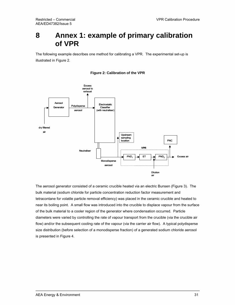
8 Annex 1: example of primary calibration of VPR
The following example describes one method for calibrating a VPR. The experimental set-up is
illustrated in Figure 2.
Figure 2: Calibration of the VPR
The aerosol generator consisted of a ceramic crucible heated via an electric Bunsen (Figure 3). The
bulk material (sodium chloride for particle concentration reduction factor measurement and
tetracontane for volatile particle removal efficiency) was placed in the ceramic crucible and heated to
near its boiling point. A small flow was introduced into the crucible to displace vapour from the surface
of the bulk material to a cooler region of the generator where condensation occurred. Particle
diameters were varied by controlling the rate of vapour transport from the crucible (via the crucible air
flow) and/or the subsequent cooling rate of the vapour (via the carrier air flow). A typical polydisperse
size distribution (before selection of a monodisperse fraction) of a generated sodium chloride aerosol
is presented in Figure 4.
Aerosol
GeneratorElectrostaticClassifier
(with neutraliser)
dry filtered
air
Monodisperse
aerosol
Polydisperse
aerosol
Excess aerosol to exhaust
Upstream sampling location
PND1 ET PND2
Dilution air
PNC
Excess air
NeutraliserVPR
Aerosol
GeneratorElectrostaticClassifier
(with neutraliser)
dry filtered
air
Monodisperse
aerosol
Polydisperse
aerosol
Excess aerosol to exhaust
Upstream sampling location
PND1 ET PND2
Dilution air
PNC
Excess air
NeutraliserVPR

VPR Calibration Procedure Restricted – Commercial AEA/ED47382/Issue 5
32 AEA Energy & Environment
Figure 3: Condensation Aerosol Generator
.
T
Aerosol
Outlet
Filtered
Carrier
Air
Vap
ou
r
Crucible
Air Flow
Vap
ou
r
Condensation
T
Aerosol
Outlet
Filtered
Carrier
Air
Vap
ou
r
Crucible
Air Flow
Vap
ou
r
Condensation
Filtered Carrier Air Aerosol
Out
Crucible Air Flow
CrucibleHeater

Restricted – Commercial VPR Calibration Procedure AEA/ED47382/Issue 5
AEA Energy & Environment 33
Figure 4 Typical size distribution of a polydisperse sodium chloride calibration aerosol
0.00E+00
1.00E+06
2.00E+06
3.00E+06
4.00E+06
5.00E+06
6.00E+06
1 10 100 1000
Particle Diameter [nm]
Nu
mb
er
Co
nce
ntr
ati
on
(d
N/
dlo
g(D
p))
[p
/cm
3]
Average Modal Diameter = 53 nm
Average GSD = 1.39
Note: This aerosol generation method is reported purely as an example. Alternative methods that
generate similarly sized particles and concentrations are equally appropriate.
The electrostatic classifier was used to select monodisperse fractions of the polydisperse calibration
aerosol and deliver the required number concentrations to the VPR (> 5000 particles cm-3 for sodium
chloride and >10,000 particles cm-3 for tetracontane), reducing the GSD (geometric standard
deviation) to around 1.2.
Two PNCs were used to simultaneously record the number concentrations upstream (at the inlet of
PND1) and downstream (at the outlet of the VPR).
Note: It is imperative that the response of these PNCs is verified before the VPR is calibrated; this is to
ensure that the two PNCs are equivalent. The upstream and downstream concentrations are directly
compared with each other to calculate the particle concentration reduction factor and volatile particle
removal efficiency of the VPR; therefore the PNCs must be compared with each other. The secondary
calibration method for PNC calibration is recommended, as detailed in the ‘Condensation Particle
Counter Calibration Procedures5’. The linearity of response in terms of the R2 coefficient must be
greater than 0.97, else the PNCs do not respond linearly over the measured concentration range. If
the two PNCs do not meet these requirements the upstream and downstream concentrations may not
be directly compared. The PNCs response at all particle sizes and concentration should be compared
and measurements taken with one PNC adjusted to align with the other PNC. Additionally the data
from the upstream and downstream PNCs must be time aligned to account for the VPR residence
time.

VPR Calibration Procedure Restricted – Commercial AEA/ED47382/Issue 5
34 AEA Energy & Environment
Additionally, care must be taken when comparing the results from two PNCs if they are not the same
model, this was particularly important in this example as one PNC had been modified to provide lower
size detection limits of 23±3 and 37±4 nm for 50 % detection efficiency (D50) and 90 % detection
efficiency (D90) respectively than the standard model of TSI PNC 3010. The AEA PNC was
unmodified having a D50 of 9.5±0.5 nm and D90 of 13.5±0.5 nm. Thus significant differences between
the concentrations reported by both PNCs would be expected if the calibration particles were smaller
than around 40 nm. For the VPR calibrations at 30 nm the AEA PNC was used in both the upstream
and downstream sampling positions through equivalent sampling lines. The downstream sampling
line was exchanged for the upstream sampling line, the number concentration was allowed to stabilise
and then the upstream sampling was reconnected to the PNC to verify that the inlet concentration had
not drifted throughout the measurements.
Identical flow paths were used to deliver the calibration particles from the electrostatic classifier to the
PNCs and the VPR inlet, thus ensuring any losses within the pipe work were the equivalent for all
measurements.
For each monodisperse diameter and nominal dilution setting the system was allowed to stabilise for
at least 1 minute before selecting the next setting. When the measurements were complete at each
nominal dilution setting the particle diameter was changed. The results were analysed to calculate the
particle concentration reduction factor at each nominal dilution setting (Figure 5).

Restricted – Commercial VPR Calibration Procedure AEA/ED47382/Issue 5
AEA Energy & Environment 35
Figure 5: Example of measured particle concentration reduction factors for 30, 50 and 100 nm diameter particles at five dilution settings.
Note: Figure 5 is an example of the measured particle concentration reduction factors, the VPR under
test required maintenance and would not have passed calibration.
The measured upstream and downstream number concentrations of 30 nm tetracontane volatile
particles are shown in Table 3. The final two columns list the measured downstream concentration
after the particle concentration reduction factor has been applied to the data and compares this with
the allowed downstream concentration (1 % of the upstream concentration). The measurement was
repeated five times and the VPR met the criteria for all repeats.
Table 3 Volatile Particle Removal Efficiency Repeat Upstream
Concentration (cm-3)
Downstream Concentration (cm-3)
PCRF Adjusted Downstream Concentration (cm-3)
Allowed Downstream Concentration (cm-3)
1 11125 0.24 353 84.72 111.25 2 10736 0.24 353 84.72 107.36 3 12399 0.34 353 120.02 123.99 4 15472 0.43 353 151.79 154.72 5 15338 0.43 353 151.79 153.38
0
2000
4000
6000
8000
10000
12000
14000
0 20 40 60 80 100 120
Potentiometer Setting (%)
PCR
F 30 nm50 nm100 nm

VPR Calibration Procedure Restricted – Commercial AEA/ED47382/Issue 5
36 AEA Energy & Environment

Restricted – Commercial VPR Calibration Procedure AEA/ED47382/Issue 5
AEA Energy & Environment 37
9 Annex 2: Example of particle concentration reduction factors (fr)
Table 4 lists the minimum number of particle concentration reduction factors required for primary
calibration for VPRs with a variable secondary diluter (PND2).ie all fifteen factors are required.
For VPRs with a fixed PND2 dilution setting only the first set of particle concentration reduction factors
would be required (highlighted in yellow).
The particle concentration reduction factors in Table 4 are shown as an example, as measured for the
VPR calibrated in Annex 1.
Table 4: Examples of particle concentration reduction factors (fr)
Primary Diluter Setting (PND1)
Secondary Diluter Setting (PND2)
Particle concentration reduction factor (fr)
1 1 313 2 1 802 3 1 1128 4 1 2147 5 1 6104 1 2 - 2 2 - 3 2 - 4 2 - 5 2 - 1 3 - 2 3 - 3 3 - 4 3 - 5 3

VPR Calibration Procedure Restricted – Commercial AEA/ED47382/Issue 5
38 AEA Energy & Environment

Restricted – Commercial VPR Calibration Procedure AEA/ED47382/Issue 5
AEA Energy & Environment 39
10 Glossary of Terms Term Acronym Definition Diesel Particulate Filter DPF A particle filter that is used within the exhaust system of a diesel
vehicle. Dilution Factor DF A measure of the degree of dilution achieved by a diluter
operating at specified conditions. Downstream Refers to the sampling location at the outlet of the VPR i.e. after
the second diluter PND2 Electrostatic Classifier Primary-standard instruments that produce highly
monodisperse, submicrometer aerosols. Evaporation Tube ET Heated tube used to vaporise volatile particles from the aerosol
sample. Gas Concentration Reduction Factor
A factor used in an optional quality control check of the VPR calculated from the measured dilution of a certified gas concentration.
High Efficiency Particulate Air Filter
HEPA An air filter capable of removing particles at a high efficiency as specified in EN1822:1998.
Particle Concentration Reduction Factor (fr)
PCRF A factor used to describe the performance of the VPR. The PCRF incorporates actual dilution and all particle losses within the VPR. PCRF is calculated from:
)()(
)(iout
iinir dN
dNdf = (12)
Where Nin (di) = upstream particle number concentration for particles of diameter di; and Nout (di) = downstream particle number concentration for particles of diameter di
Particle Number Counter
PNC An instrument used to count particle number concentration.
Particle Number Diluter PND Instrument used to dilute the number of particles in the sample. Upstream Refers to the sampling location at the inlet of the VPR i.e. PND1
inlet Volatile Particle Removal Efficiency
A measure of the VPR’s ability to vaporise volatile particles.
Volatile Particle Remover
VPR Instrument capable of diluting the sample in one or more stages to achieve a particle number concentration below the upper threshold of the single particle count mode of the PNC and to achieve a gas temperature below 35 °C at the inlet to the PNC while suppressing nucleation within the sample.

VPR Calibration Procedure Restricted – Commercial AEA/ED47382/Issue 5
40 AEA Energy & Environment

AEA Energy & Environment
The Gemini Building Fermi Avenue Harwell International Business Centre Didcot Oxfordshire OX11 0QR Tel: 0845 345 3302 Fax: 0870 190 6318 E-mail: [email protected] www.aea-energy-and-environment.co.uk