Embed Size (px)
Citation preview
Voltage Control and Coordination at ISO New England
Xiaochuan LuoTechnical ManagerISO New England Inc
FERC WorkshopDecember 1st, 2011
Outline
• Overview of New England’s electric power system
• Responsibilities of voltage control
• FERC’s five questions and answers
• Summary
2
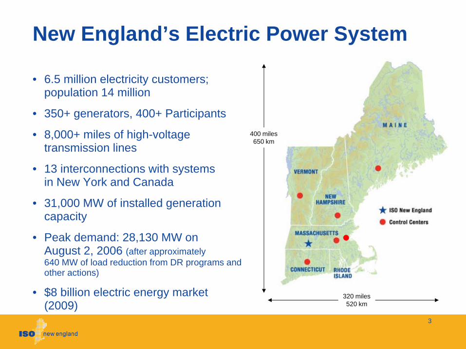
New England’s Electric Power System
• 6.5 million electricity customers; population 14 million
• 350+ generators, 400+ Participants
• 8,000+ miles of high-voltage transmission lines
• 13 interconnections with systemsin New York and Canada
• 31,000 MW of installed generation capacity
• Peak demand: 28,130 MW on August 2, 2006 (after approximately 640 MW of load reduction from DR programs and other actions)
• $8 billion electric energy market (2009)
3
400 miles650 km
320 miles520 km

ISO – Local Control Center (LCC) Start-up Dates
Manchester June 1, 1970
NH ESCC
Connecticut Valley Electric ExchangeJanuary 1, 1964
CONVEX
Rhode IslandE. Mass Energy ControlApril 1, 1969
REMVEC
AugustaNovember 1, 1969Maine
Independent System Operator- New EnglandNovember, 1971
ISO-NERTO
VELCO
Rutland, VTApril 1, 2005
BostonDecember 1, 2007NSTAR
4
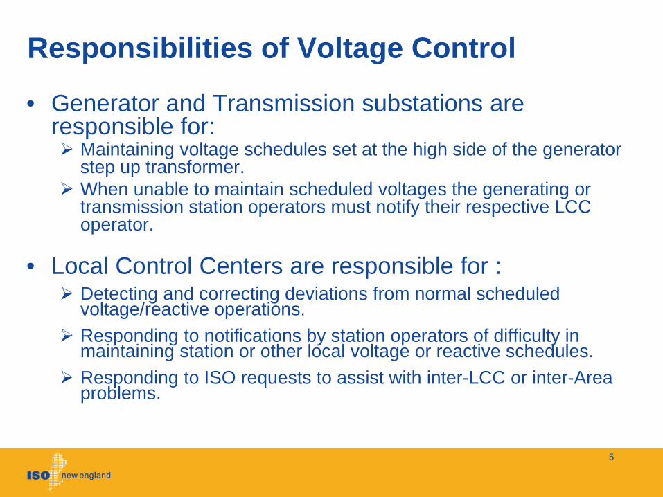
Responsibilities of Voltage Control
• Generator and Transmission substations are responsible for:
Maintaining voltage schedules set at the high side of the generator step up transformer.When unable to maintain scheduled voltages the generating or transmission station operators must notify their respective LCC operator.
• Local Control Centers are responsible for :Detecting and correcting deviations from normal scheduled voltage/reactive operations. Responding to notifications by station operators of difficulty in maintaining station or other local voltage or reactive schedules. Responding to ISO requests to assist with inter-LCC or inter-Area problems.
5
Responsibilities (cont’d)
• Local Control Centers also monitor and supervise the following within their territories:
Voltage schedules and limits
Unit MVAR loadings, capabilities and reserves
Shunt capacitor and reactor dispatches
Transformer voltage schedules or fixed tap settings
MVAR flows between the AC and HVDC facilities
Static VAR Compensator operation (must be coordinated with ISO)
Line switching for voltage /reactive control (must be coordinated with ISO and other LCCs)
Load management (must be coordinated with ISO)
6
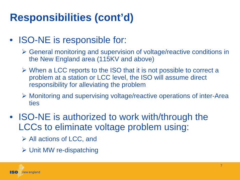
Responsibilities (cont’d)
• ISO-NE is responsible for:General monitoring and supervision of voltage/reactive conditions in the New England area (115KV and above)
When a LCC reports to the ISO that it is not possible to correct a problem at a station or LCC level, the ISO will assume direct responsibility for alleviating the problem
Monitoring and supervising voltage/reactive operations of inter-Area ties
• ISO-NE is authorized to work with/through the LCCs to eliminate voltage problem using:
All actions of LCC, and
Unit MW re-dispatching
7
a. Describe the pre-scheduling and real-time processes that involve the commitment or dispatch of reactive resources from a reliability perspective. What applications or tools are used to evaluate reactive or voltage support needs from this perspective?
8
FERC Questions
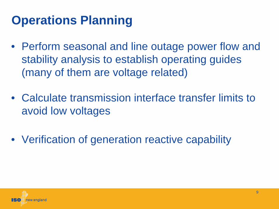
Operations Planning
• Perform seasonal and line outage power flow and stability analysis to establish operating guides (many of them are voltage related)
• Calculate transmission interface transfer limits to avoid low voltages
• Verification of generation reactive capability
9
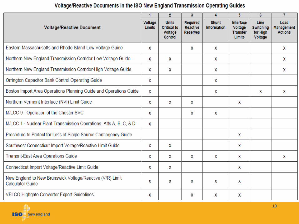
10

Day Ahead
• Transmission interface limits (MW) are used as a surrogate for the voltage limits
• Double contingency proxy limits are enforced for pre-defined areas in clearing the day-ahead market
“Line – Line” contingency
“Line – Generation” contingency
Consider 30 minutes system responses
• System reactive resources and/or must run units are committed per system operating guides to control high / low voltage conditions
11
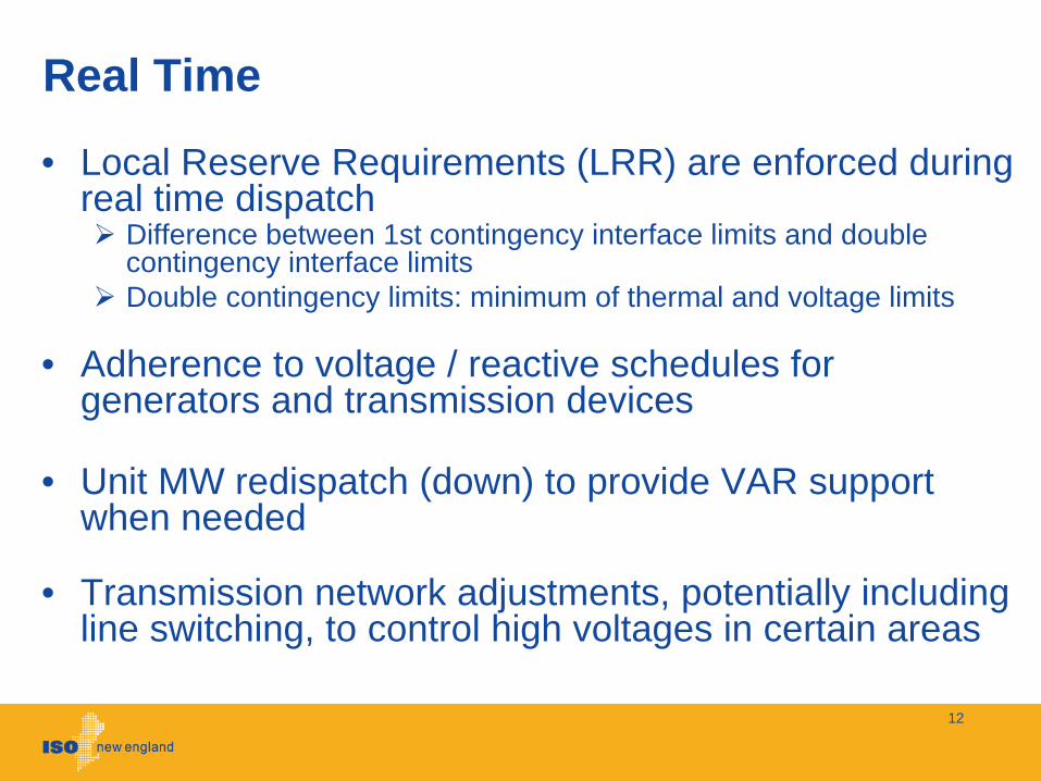
Real Time
• Local Reserve Requirements (LRR) are enforced during real time dispatch
Difference between 1st contingency interface limits and double contingency interface limitsDouble contingency limits: minimum of thermal and voltage limits
• Adherence to voltage / reactive schedules for generators and transmission devices
• Unit MW redispatch (down) to provide VAR support when needed
• Transmission network adjustments, potentially including line switching, to control high voltages in certain areas
12
Applications or Tools
• EMS environment: Alstom’s PWRFLOW and RTCAIn-house developed ILC and DOUBLEC
• Operations Planning and Day AheadPSSE (Power flow and stability analyses)TTC Calculator based on PowerWorld (interface limits)
13

b. Describe the pre-scheduling and real-time processes that involve the commitment or dispatch of reactive resources from an economicperspective. What applications or tools are used to evaluate reactive or voltage support needs from this perspective?
Answer: No processes exist that commit or dispatch reactive resources from an economic perspective.
14
FERC Questions
c. Explain whether and how pre-scheduling, real-time and post analysis evaluations are performed on the bulk electric system or on lower voltage systems to maximize opportunities for additional reliability or economic transactions.
15
FERC Questions
Load Power Factor Requirements
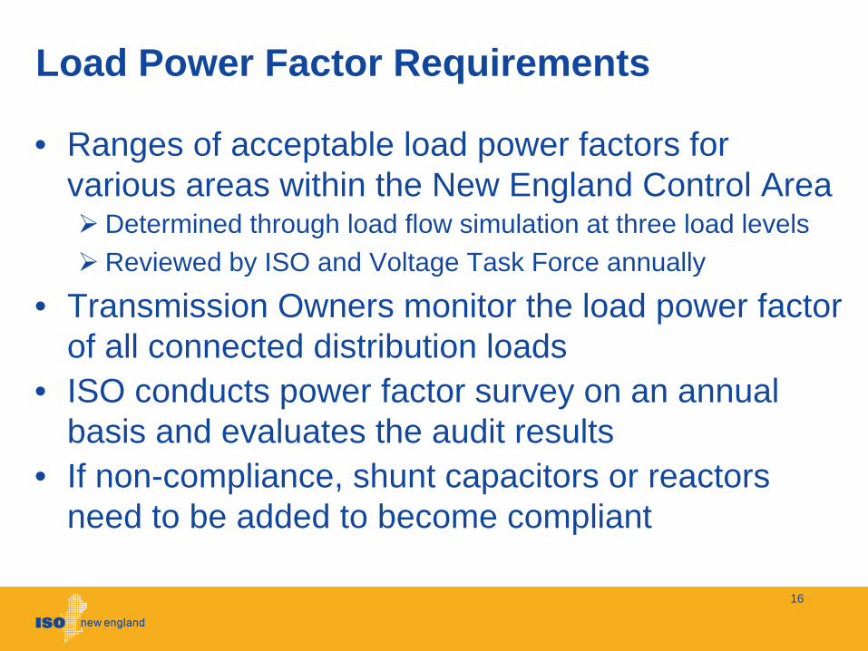
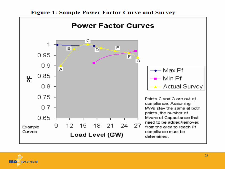
• Ranges of acceptable load power factors for various areas within the New England Control Area
Determined through load flow simulation at three load levelsReviewed by ISO and Voltage Task Force annually
• Transmission Owners monitor the load power factor of all connected distribution loads
• ISO conducts power factor survey on an annual basis and evaluates the audit results
• If non-compliance, shunt capacitors or reactors need to be added to become compliant
16
17

Load Power Factor Use
• Survey data utilized to create accurate models of system performance for off-line analysis
• Used in operating studiesAccurate load power factors are often critical for optimization of reactive resource and system voltage control
• Used to develop region-wide assumptions for load power factor for system planning work
18
d. Describe the situations where the dispatch of reactive resources may limit System Operating Limits or whether and how more transactions could be supported.
19
FERC Questions
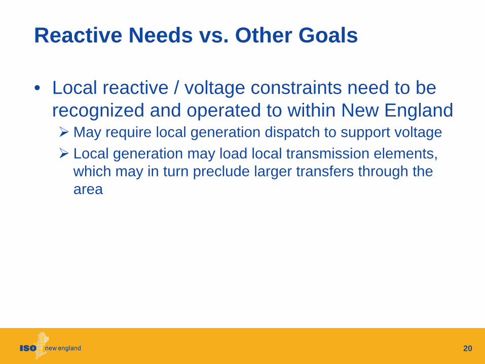
Reactive Needs vs. Other Goals
• Local reactive / voltage constraints need to be recognized and operated to within New England
May require local generation dispatch to support voltageLocal generation may load local transmission elements, which may in turn preclude larger transfers through the area
20
e. Describe how reactive power needs of the distribution system or loads are coordinated or optimized.
21
FERC Questions
Bulk Substation
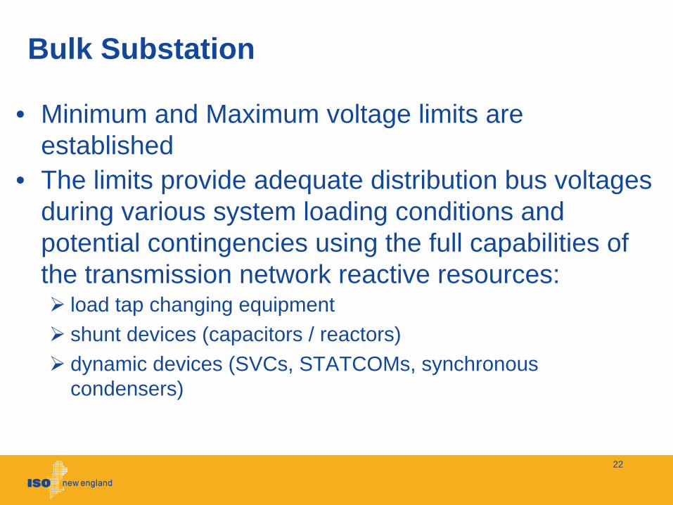
• Minimum and Maximum voltage limits are established
• The limits provide adequate distribution bus voltages during various system loading conditions and potential contingencies using the full capabilities of the transmission network reactive resources:
load tap changing equipmentshunt devices (capacitors / reactors)dynamic devices (SVCs, STATCOMs, synchronous condensers)
22
Distribution Reactive Coordination
• Utility specific, dependent on system evolution, composition, load distribution, network scarcity and system strength
• Automated controls focused power factor regulation and/or voltage control
Power factor regulation may be based upon loss minimization on the distribution network
• Manual switching focused power factor regulation and/or voltage control
Installed distribution capacitors and transformer fixed tap-ratios may be seasonally switched depending on distribution needs
• A “one-size fits all” approach does not work within New England footprint
Diverse types of distribution networks and customer density
23
Summary
• Coordinated hierarchical voltage control is adopted in the New England region
• Dispatch of reactive resources is driven by the system RELIABILITY need
• Varieties of tools or applications are used in operations planning, system operation and markets to maintain proper level of system voltage
24

Future Plans
• On-line voltage stability assessment
• Voltage profile optimization
• EMS/DMS integration
25