Embed Size (px)
Citation preview
TM 11-6625-524-14-4
TECHNICAL MANUAL
OPERATOR’S , ORGANIZATIONAL,
DIRECT SUPPORT AND GENERAL SUPPORT
MAINTENANCE MANUAL
FOR
VOLTMETER, ELECTRONIC AN/URM-145D
(MILLIVAC INSTRUMENTS MODEL MV-828A)
(NSN 6625-01-119-7271)
HEADQUARTERS, DEPARTMENT OF THE ARMY
24 MAY 1982

SAFETY STEPS
IS THE VICTIM
TO FOLLOW IF SOMEONE
OF ELECTRICAL SHOCK
DO NOT TRY TO PULL OR GRAB THE INDIVIDUAL
IF POSSIBLE , TURN OFF THE ELECTRICAL POWER
IF YOU CANNOT TURN OFF THE ELECTRICAL-
POWER, PULL, PUSH, OR LIFT THE PERSON TOSAFETY USING A WOODEN POLE OR A ROPE OR -
SOME OTHER INSULATING MATERIAL
SEND FOR HELP AS SOON AS POSSIBLE
AFTER THE INJURED PERSON IS FREE OF
CONTACT WITH THE SOURCE OF ELECTRICAL
S H O C K , M O V E T H E P E R S O N A S H O R T D I S T A N C E .
AWAY AND IMMEDIATELY START ARTIFICIAL
RESUSCITATION
A

TM 11-6625-524-14-4C1
HEADQUARTERSDEPARTMENT OF THE ARMY
Washington, DC,
OPERATOR’S, ORGANIZATIONAL, DIRECT SUPPORT,AND GENERAL SUPPORT MAINTENANCE MANUAL
FORVOLTMETER, ELECTRONIC AN/URM-145D(MILLIVAC INSTRUMENTS MODEL MV-828A)
(NSN 6625-01-119-7271)
TM 11-6625-524-14-4, 24 May, 1982, is changed as follows:1.2.3.
13 February 1984
New or changed material is indicated by a vertical bar in the margin of the page.Added or revised illustrations are indicated by a vertical bar in front of the figure caption.Remove and insert pages as indicated below:
Remove
i and ii1-1 and 1-23-1 and 3-24-1 through 4-45-5 and 5-6Figure FO-1Figure FO-2
Insert
i and ii1-1 and 1-23-1 and 3-24-1 through 4-45-5 and 5-6Figure FO-1Figure FO-2
4. File this change sheet in front of the publication for reference purposes.

By Order of the Secretary of the Army:
Official:
JOHN A. WICKHAM JR.General, United States Army
Chief of Staff
ROBERT M. JOYCEMajor General, United States Army
The Adjutant General
DISTRIBUTION:To be distributed in accordance with DA Form 12-36B requirements
for AN/URM-145.

TM 11-6625-524-14-4
HEADQUARTERSTechnical Manual
No. 11-6625-524-14-4 DEPARTMENTWashington, DC,
OPERATOR’S, ORGANIZATIONAL, DIRECT SUPPORT,AND GENERAL SUPPORT MAINTENANCE MANUAL
FORVOLTMETER, ELECTRONIC AN/URM-145D(MILLIVAC INSTRUMENTS MODEL MV-828A)
(NSN 6625-01-119-7271)
REPORTING ERRORS AND RECOMMENDING IMPROVEMENTS
You can help improve this manual. If you find anymistakes or if you know of a way to improve the pro-cedures, please let us know. Mail your letter, DA Form2028 (Recommended Changes to Publications or BlankForms), or DA Form 2028-2 located in the back of thismanual direct to: Commander, US Army Communications -Electronics Command and Fort Monmouth, ATTN: DRSEL-ME-MP,Fort Monmouth, New Jersey 07703.
In either case, a reply will be furnished direct to you.
TABLE OF CONTENTSParagraph
CHAPTER 1. INTRODUCTIONSection I. General
Scope . . . . . . . . . . . . . . . . . . . . . . . . . . . . . . . . . . . . . . . .Consolidated index of Army publications
and blank forms . . . . . . . . . . . . . . . . . . . . . . . . . . . .Maintenance forms, records and reports . . . . . . .Reporting equipment improvement
recommendations (EIR) . . . . . . . . . . . . . . . . . . . . . .Administrative storage . . . . . . . . . . . . . . . . . . . . . . .Destruction of Army electronics materiel . . . . .
II. Description and dataDescription and use . . . . . . . . . . . . . . . . . . . . . . . . . .Technical characteristics . . . . . . . . . . . . . . . . . . . .
CHAPTER 2. INSTALLATIONPackaging data . . . . . . . . . . . . . . . . . . . . . . . . . . . . . . .Unpacking . . . . . . . . . . . . . . . . . . . . . . . . . . . . . . . . . . . .Checking unpacked equipment . . . . . . . . . . . . . . . . . .Items comprising an operable equipment . . . . . . .
1-1
1-21-3
1-41-51-6
1-71-8
2-12-22-32-4
OF THE ARMY24 May 1982
Page
This manual is an authentication of the manufacturer’s commercial literature
1-1
1-11-1
1-11-11-1
1-11-2
2-12-12-12-1
which, through usage, has been found to cover the data required to operate andmaintain this equipment. Since the manual was not prepared in accordance withmilitary specifications and AR–310–1, the format has not been structured toconsider levels of maintenance.
Change 1 i

TM 11-6625 -524-14-4
CHAPTER 3
CHAPTER 4.
CHAPTER 5.Section I.
II.
III.
CHAPTER 6.
CHAPTER 7.
Section I.
II.
OPERATING INSTRUCTIONSGeneral . . .. . . . . . . . . . . . . . . . . . . . . . .Power Line Requirements . . . . . . . . . . . . . . . . . . . . . .General precautions for RF measurements . . . . . .Control sand indicators . . . . . . . . . . . . . . . . .Operating procedures . . . . . . . . . . . . . . . . . . . . . . . . .
CIRCUIT FUNCTIONINGGeneral . . . . . . . . . . . . . . . . . . . . . . . . . . . . .Detailed description, voltmeter . . . .. . . . . . .Detailed description, probe and terminations. .
GENERAL SUPPORT MAINTENANCE INSTRUCTIONSTools and Test EquipmentTools and test equipment required . . . . . . . . . . . .Cabinet removal . . . . . . . . . . . . . . . . . . . . . .TroubleshootingGeneral . . . . . . . . . . . . . . . . . . . . . . . . . . . . . .Inoperative . . . . . . . . . . . . . . . . . . . . . . . .Erractic or intermittent. . . . .. . . . . . . . . . . . . . .DC modulator driver . . .. . . . . . . . . . . . . . . . . . . .Post amplifier, synchronous demodulator andreference amplifier . . . . . . . . . . . . . . . . . . . . . .Narrow band pre-amplifier . . . . . . . . . . . . . . . . . . . .DC modulator . . . . . . . . . . . . . . . . . . . . . . . . .Power and range switches . . . . . . . . . . . . . . . .Feedback, linearizing and calibrationcontrols network . . . . . . . . . . . . . . . . . . . . . . . . .MaintenanceProbe and diode cartridge . . . . . . . . . . . . . . . . . . . .Probe terminations . . . . . . . . . . . . . . . . . . .Switch cleaning . . . . . . . . . . . . . . . . . . .
GENERAL SUPPORT TESTING PROCEDURESGeneral . . . . . . . . . . . . . . . . . . . . . . . .Test equipment required . . . . . . . . . . . . . . . . . . .Power supply test . . . . . . . . . . . . . . . . . . .Pre-amplifier and post amplifier test . . . . .Voltage accuracy test . . . . . . . . . . . . . . .
SHIPMENT AND LIMITED STORAGE AND DEMOLITION TOPREVENT ENEMY USEShipment and limited storageDisassembly of equipment . . . . . . . . . . . .Repackaging for shipment or limited storage . .Demolition of materiel to prevent enemy useAuthority for demolition . . . . . . . . . .Methods of destruction .. . . . . . . . . .
Paragraph
3-13-23-33-43-5
4-14-24-3
5-15-2
5-35-45-55-6
5-75-85-95-10
5-11
5-125-135-14
6-16-26-36-46-5
7-17-2
7-37-4
Page
3-1 3-13-13-1
4-14-14-5
5-15-2
5-25-35-35-3
5-35-45-45-5
5-5
5-55-75-7
6-16-16-16-26-3
7-17-1
7-17-2
i i
3-1

TM 11-6625-524-14-4
APPENDIX AB
Section I.
I I I .APPENDIX C
DSection I.
I I .I I I .
IV .APPENDIX E
Table of Contents (Continued)
Page
REFERENCES . . . . . . . . . . . . . . . . . . . . . . . A-1COMPONENTS OF END ITEM LIST . . . . . . . . . . . . . .I n t r oduc t i on . . . . . . . . . . . . . . . . . . . . . . B-1Integral components of end item . . . . . . . B-3Basic issue items . . . . . . . . . . . . . . . . . . . . . . . . B-4ADDITIONAL AUTHORIZATION LIST
(Not applicable)MAINTENANCE ALLOCATIONInt roduct ion . . . . . . . . . . . . . . . . . . . . . . . . . D-1Maintenance Allocation Chart . . . . . . . . . . . . D-3Tool and Test Equipment Requirements . . . . D-4Remarks . . . . . . . . . . . . . . . . . . . . . . . . . . . . . D-5EXPENDABLE SUPPLIES AND MATERIALS LIST
(Not applicable)
iii
I I .
TM 11-6625-524-14-4
Figure No.
1-12-13-13-24-14-24-34-44-55-15-26-1
F0-1F0-2
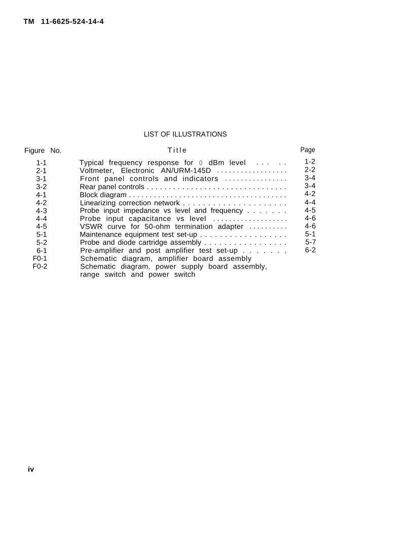
LIST OF ILLUSTRATIONS
T i t l e
Typical frequency response for 0 dBm level . . . . .Voltmeter, Electronic AN/URM-145D . . . . . . . . . . . . . . . . . .Front panel controls and indicators . . . . . . . . . . . . . . . .Rear panel controls . . . . . . . . . . . . . . . . . . . . . . . . . . . . . . . .Block diagram . . . . . . . . . . . . . . . . . . . . . . . . . . . . . . . . . . . . . .Linearizing correction network . . . . . . . . . . . . . . . . . . . . .Probe input impedance vs level and frequency . . . . . . .Probe input capacitance vs level . . . . . . . . . . . . . . . . . . .VSWR curve for 50-ohm termination adapter . . . . . . . . . .Maintenance equipment test set-up . . . . . . . . . . . . . . . . . .Probe and diode cartridge assembly . . . . . . . . . . . . . . . . .Pre-amplifier and post amplifier test set-up . . . . . . .Schematic diagram, amplifier board assemblySchematic diagram, power supply board assembly,range switch and power switch
Page
1-22-23-43-44-24-44-54-64-65-15-76-2
iv

TM 11-6625-524-14-4
CHAPTER 1
INTRODUCTION
Section I. GENERAL
1-1 SCOPEThis manual describes Voltmeter, Electronic AN/URM-145D and provides operator andmaintenance instructions, testing procedures and schematic diagrams.
1-2 CONSOLIDATED INDEX OF ARMY PUBLICATIONS AND BLANK FORMSRefer to the latest issue of DA Pam 310-1 to determine whether there are newedit ions, changes, or addit ional publ ications pertaining to this equipment.
1-3 MAINTENANCE FORMS, RECORDS, AND REPORTSa. Reports of Maintenance and Unsatisfactory Equipment. Department of the Army
forms and procedures used for equipment maintenance will be those described by TM38-750, The Army Maintenance System.
b. Report of Packaging and Handling Deficiencies. Fill out and forward SF 364(Report of Discrepancy (ROD)) as prescribed in AR 735-11-2/DLAR 4140.55/NAVMATINST4355.73A/AFR 400-54/MC0 4430.3F.
c. Discrepancy in Shipment Report (DISREP) (SF 361). Fill out and forward Dis-crepancy in Shipment Report (DISREP) (SF361) as prescribed in AR 55-38/NAVSUPINST4610.33C/AFR 75-18/MC0 P4610.19D/DLAR 4500.15.
1-4 R EPORTING EQUIPMENT IMPRo vE M E N T R E C O M M E N D A T I O N S ( E I R )If your AN/URM-145D needs improvement, let us know. Send us an EIR. You, the user,are the only one who can tell us what you don’t like about your equipment. Let usknow why you don’t like the design. Tell us why a procedure is hard to perform. Putit on an SF 368(Quality Deficiency Report). Mail it to Commander, US Army Communi-cations-Electronics Command and Fort Monmouth, ATTN: DRSEL-ME-MP, Fort Monmouth NJ07703. We’ll send you a reply.
1-5 ADMINISTRATIVE STORAGEAdminstrative storage of equipment issued to and used by Army activities shall bein accordance with TM 740-90-1.
1-6 DESTRUCTION OF ARMY ELECTRONICS MATERIELDestruction of Army electronics materiel to prevent enemy use shall be in accordancewith TM 750-244-2.
Section II. Description and Data
1-7 DESCRIPTION AND USEa. Voltmeter, Electronic AN/URM-145D is a sensitive, wide band instrument for
the measurements of voltages from 100 microvolt (µV)to 3 volts (V) spanning a fre-quency range of 20 kilohertz (KHz) to 600 megahertz (MHz).
b. The general` purpose rf probe supplied employs a fullwave germanium diode de-t ec t i ng c i r cu i t . In the square-law region(100µV to 30mV) the voltmeter is true RMSresponding. In the transition region(30mV to 1V)the characteristics of the probe’sdetecting circuit changes gradually from RMS to peak. In the linear region (1V to3V) the voltmeter is peak responding.
Change 1 1-1

TM 11-6625-524-14-4
c. The type BNC 50-ohm termination adapter supplied has a VSWR of less than1.2:1 up to 600MHz. The adapter has a 5 watt max. power rating.
d. The high impedance probe tip supplied allows for direct high impedancemeasurements up to 250MHz. However, a short wire should be substituted for theground lead when using above 100MHz to minimize the effects of ground lead in-duction.
e. The main controls required to operate the voltmeter are on the front panel.Several minor controls are on the rear panel.
1-8 TECHNICAL CHARACTERISTICSVoltage range . . . . . . . . . . . . . . . . . . . . . 100µV to 3V, 8 ranges; 0.001V to 3V full scaledBm range . . . . . . . . . . . . . . . . . . . . . . . . . -60 to + 23, 8 ranges in 10dB steps per rangeFrequency range . . . . . . . . . . . . . . . . . . . 20KHz to600MHzFrequency response . . . . . . . . . . . . . . . . True RMS up to 30mV, peak reading above 1VWide band accuracy . . . . . . . . . . . . . . . . (see Fig. 1-1)
0.003V Full Scale toFrequency 0.001V Full Scale Range 3V Full Scale Ranges
20KHz to 100MHz ±15% of full scale ±10% of full scale100MHz to 400MHz ±10% of full scale400MHZ to 600MHZ
±5% of full scale±15% of full scale ±10% of full scale
INPUT IMPEDANCE . . . . . . . . . . . . . . . . . . .V.S.W.R. . . . . . . . . . . . . . . . . . . . . . . . . . .CREST FACTOR . . . . . . . . . . . . . . . . . . . . . .MAXIMUM INPUTS . . . . . . . . . . . . . . . . . . . .DC OUTPUT . . . . . . . . . . . . . . . . . . . . . . . . .
RISE TIME . . . . . . . . . . . . . . . . . . . . . . . . .
INDICATOR . . . . . . . . . . . . . . . . . . . . . . . . .
LINE VOLTAGE & POWER . . . . . . . . . . . . . .DIMENSIONS&WEIGHT . . . . . . . . . . . . . . .
Approx. 2.2 pf and 200KLess than 1.2:1 at 600MHz450 to 1.4 (function of input voltages)RF: 42V P-P or 15V RMS; DC: 400V1.0V, 1mA max. at full scale, linear. Impedanceload of 2K , ±1% required1 sec. on the 0.001V full scale range, de-creasing to 100 millisec. about the 0.01V fullscale rangePrecision 5.5” taut band meter movement,mirror-backed dial and knife edge pointer. Ex-panded linear dial scales except dBm.115V or 230V AC +20%, 45-1000Hz; less than 12W9“ H x 6.5”W x 11.25” D. Weight approx. 12 lbs.
F i g u r e 1 - 1 : T y p i c a l f r e q u e n c y r e s p o n s e for 0 d B m l e v e l .
1-2

TM 11-6625-524-14-4
CHAPTER 2
INSTALLATION
2-1 PACKAGING DATAa. Voltmeter, Electronic AN/URM-145D may arrive packed for either domestic or
overseas shipment.b. When Voltmeter, Electronic AN/URM-145D is packed for overseas shipment, it
is placed in a corrugated carton surrounded with packing material. The carton issealed with gummed tape. The boxed equipment is then placed in a moisture-vapor-proof barrier, which is heatsealed, and this package is placed in a waterproofcorrugated carton. The technical manual is placed under the lid and the carton issealed with waterproof tape.
2-2 UNPACKINGa. For unpacking overseas shipment equipment proceed as follows:
(1) Open the outer corrugated carton and break the sealed moisture-vapor-proof barrier. Lift out the inner corrugated carton.
(2) Open the inner corrugated carton. Remove the equipment in its packingmaterial and remove the packing material.
b. For unpacking domestic shipment the instructions above also apply. If aheavy wrapping paper has been used, remove it carefully and take out the equip-ment.
2-3 CHECKING UNPACKED EQUIPMENTa. Inspect the equipment for damage incurred during shipment. If the equipment
has been damaged, report the damage on SF 364 (para 1-3b).b. Check the equipment for completeness against the packing slip. Report all
discrepancies in accordance with paragraph 1-3. The equipment should be placed inservice even though a minor part that does not affect proper functioning is missing.
c. After the equipment has been thoroughly checked, clean all items with asoft cloth. Apply cleaning solvents only as necessary.
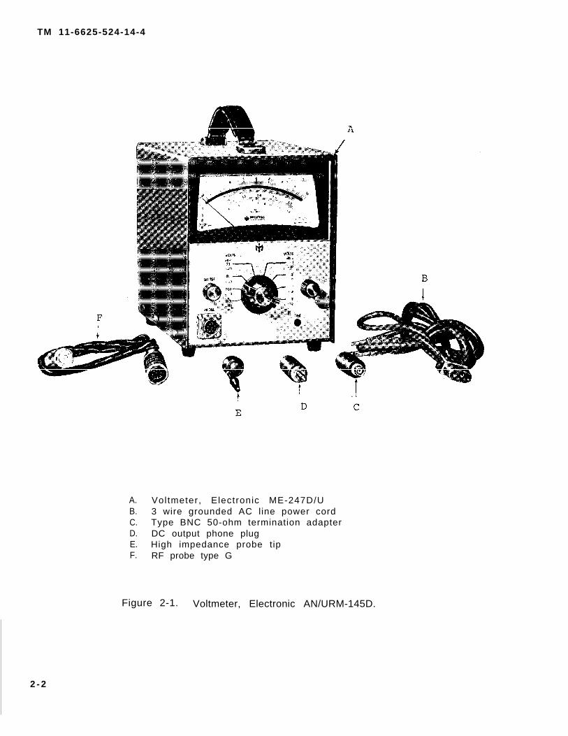
2-4 ITEMS COMPRISING AN OPERABLE EQUIPMENT (figure 2-1)a. Voltmeter, Electronic ME-247D/U.b. 3 wire grounded AC line power cord.c. Type BNC 50-ohm termination adapter.d. DC output phone plug.e. High impedance probe tip.f . RF probe type G.
2-1
TM 11-6625-524-14-4
A. Voltmeter, Electronic ME-247D/UB. 3 wire grounded AC line power cordC. Type BNC 50-ohm termination adapterD. DC output phone plugE. High impedance probe tipF. RF probe type G
Figure 2-1. Voltmeter, Electronic AN/URM-145D.
2 - 2

TM 11-6625-524-14-4
CHAPTER 3
OPERATING INSTRUCTIONS
3-1 GENERALThis chapter should be read carefully before using the voltmeter. It contains infor-mation necessary for proper operation of the voltmeter. To achieve valid readings,proper switch settings are required. Controls, with the funct ion of each, are l istedin paragraph 3-4. The controls are shown in figures 3-1 and 3-2. Operating pro-cedures are described in paragraph 3-5.
3-2 POWER LINE REQUIREMENTSThe voltmeter can be used on either 115 or 230V AC power line. A line voltageselector slide switch, located on the serial/power plate, must be set to agree withthe line voltage to be used.The voltmeter will operate on power line frequencies from 45Hz to 1000Hz. Unlessotherwise specif ied, the AC l ine reject ion ( input) f i l ter, is adjusted for use on a60Hz power line frequency. For operation on another power line frequency, it is ad-v isab le to re tune the f i l te r .
3-3 GENERAL PRECAUTIONS FOR RF MEASUREMENTSNOTE
Maximum Allowable Overload: Damage to the diode cartridge may result shouldthe following input limits be exceeded:
RF: 15V RMS or 42V P-P DC: 400VNOTE
The manufacturer’s warranty does not apply to burned-out diode cartridges.
a. Overload recovery: Should any range be momentarily overloaded, especiallythe more sensitive ranges, it is advisable to turn the RANGE switch to the 0.03vfull sca le pos i t ion to fac i l i ta te a fas ter over load recovery .
b . Power d iss ipat ion ra t ing: Termination adapters are designed for 5 watt dis-sipation. Do not exceed 5 watt RF.
c. Mis-termination: High frequency signal generators have terminated outputtransmission l ines. The terminating resistance, corresponding to the character-istics impedance of the transmission line, is usually installed between the out-put terminals at the free end of the transmission line. Some generators may havethe transmission l ine terminated in i ts characterist ic impedance internal ly at theoutput connector. In this case, i f the external transmission l ine is also in 50 ,serious measuring errors may result. TO avoid this mis-match, the user must checkthe generator in question to determine i f the l ine is internal ly terminated. I fsuch is the case, the resistor should be disconnected, allowing the 50 terminationof the voltmeter’s probe to become the required output matching resistance. If itis not desirable to remove the internal termination resistor, an open circuitadapter should be used.
d. Measurements using the Hi Impedance Tip: Care must be exercised in measuringlow signal levels because of possible stray RF pick-up. The lowest level at whichthe tip is useful will depend upon the strength of the stray RF field. Since theprobe is a very wide-band device (20KHz to 600MHz), any RF signal present within theprobe’s response (AM-FM-TV broadcasting. point-to-point communications, etc.) maybe detected. In addition, above 100MHz, -
Plus the probe’s shunt capacitance, maythe inductance of the tip and ground lead,cause resonances, creating large measuring
Change 1 3-1

TM 11-6625-524-14-4
errors . However, the probe is still useful for relative readings. Because of itsshunt capacitance and resistance, the effective impedance drops appreciable above100MHz.
3-4 CONTROLS AND INDICATORSa. Front panel (figure 3-1)
(1) POWER Switch - a two position ON-OFF switch. Connects AC power to thevoltmeter at the ON position.
(2) RANGE Selector Switch - enables the selection of any one of the eight(8) RF voltage or dBm measuring ranges.
(3) SET REF Adjust Control - is used to electr ical ly zero the voltmeter,under no input signal conditions, to the meter’s SET REF indication.
(4) Meter - RF voltage measurements are read on the top two (2) meter’s dialscales. All measurements should be read between 30% and 100% of full scale as thespecified accuracies will apply only to those readings. The 1 and 2 marks on thesecond dial scale refer to 100µV and 200µV and apply only to the .001V full scalerange. dBm measurements are read on the dBm (1mV, 50 ohm) dial scale.
(5) Meter Mechanical Zero Adjust - provides mechanical zeroing of the meterpointer and is performed with the voltmeter de-energized.
(6) RF Input PROBE Connector - a 9 pin Amphenol type which accepts the probe.(7) AC LINE Pilot Light - indicates AC power is applied to the voltmeter
and is operational.b. Rear panel (figure 3-2)
(1) POWER Connector - accepts the 3 wire grounded AC line power cord.Voltage and frequency requirements are marked on the serial/power plate.
(2) FUSE Holder - contains a 0.3 amp “S1o-Blo” fuse. Always replace withthe same type and manufacture as factory installed.
(3) LINE VOLTAGE Selector Switch - slide switch for either 115V or 230V ACline operation and must be set to agree with the line voltaqe to be used.
(4) DC OUTPUT Connector - phone type jack for obtaining a DC voltage whichis direct ly proport ional to the ful l scale reading of the meter. DC output 3 circuitphone plug furnished. Impedance load of 2K (1.98K to 2.02K )is required.
(5) Serial/Power Plate.(6) Calibration Controls Board.(7) Calibrat ion Adjust Controls - provides individual range l inearization
correction adjustments.
3-5 OPERATING PROCEDURESAttach the probe to its front panel connector by lining up the key-way of the probeinput connector with the mating key of the probe plug. Push the plug firmly intothe connector and secure by rotating (clock-wise) the plug’s collar until locked.Select the appropriate probe termination. Attach to the probe’s threaded end, fingertight. Use the high impedance tip for direct measurement or use the 50-ohm ter-mination adapter for measurements in 50-ohm systems.Insert the 3 wire grounded AC line power cord into its polarized power connector.Ascertain that the line voltage selector switch is set to and agrees with the linevoltage source to be used.Prior to energizing the-voltmeter, check and if necessary, adjust the meter’smechanical zero. To re-adjust, slowly rotate the mechanical zero adjust screw until(SET REF) indication occurs. The adjustment is properly made only when the pointeris traveling in the direction opposite to the turn of the adjust screw.Select the desired measuring range. If the level of measurement to be taken is un-known, turn the range selector switch to the 3V full scale range.
3-2

TM 11-6625-524-14-4
Figure 3-1. Front panel controls and indicators.
Figure 3-2. Rear panel controls.
3-3
TM 11-6625-524-14-4
Turn the POWER selector switch to ON. With the RF probe and its termination con-nected to the de-energized signal source, slowly rotate the SET REF adjust con-trol until a SET REF indication occurs. This adjustment should be made carefully,especially on the lower, more sensitive ranges.The voltmeter is ready for use. If the level of measurement shows less than 30% offull scale, rotate the RANGE selector switch to a range position where the meterreading indicates between 30% and 100% of full scale. To obtain readings in dBm,add dBm meter reading (red scale on meter dial) to the dBm setting of the RANGEselector switch.
CAUTIONDamage to the probe’s diode cartridge may result if the input exceeds 42VP-P, 15V RMS or 400V DC.
When measuring low level RF voltages, always take precautions to avoid the possibil-ity of erroneous readings resulting from hum, noise or stray rf pickup. Althoughall low freqeuncy hum and noise is attenuated at the input by 60dB, it is stillpossible for high level unwanted signals to get through and cause errors. The besttest for this condition is to reduce the test signal to zero level and note whetherthe voltmeter continues to read some spurious signal level. In some cases, extrashielding may be necessary around the probe connections to reduce stray field pick-up. Typical sources of spurious radiation are induction or dielectric heating units,diathermy machines, local radio transmitters, grid dip meters, and amplifiers withparasitic oscillations.Operation of the voltmeter in strong 60 Hertz (Hz) magnetic fields, such as thosesurrounding unshielded power transformers, should be avoided. The magnetic fieldinduces small 60Hz currents in the amplifier section of the voltmeter which, dueto the extremely high gain at this frequency, appear as an indication on the meter.
3-4
TM 11-6625-524-14-4
CHAPTER 4
CIRCUIT FUNCTIONING
4-1 G E N E R A LThe basic circuitry of the voltmeter is best understood by reference to the blockdiagram, figure 4-1.
a. The input signal is sampled and detected by the rf probe. The direct current(dc) output signal from the probe, after passing through the attenuator section ofthe range selector switch, goes through an input filter which rejects power linefrequency components which might cause a measuring error.
b. A single-pole, double-throw, solid-state dc modulator then converts the dcsignal into a nearly symmetrical square wave.
c. The square wave is impedance matched and amplified by a high impedance,narrow band preamplifier. A narrow band filter in the preamplifier’s feedbackfurther improves the signal-to-noise rat io.
d. The preamplif ier output is further ampli f ied in the post ampli f ier stage.e. The modulated alternating current (at) signal from the post amplifier stage
is rectified by a synchronous demodualtor and the resultant dc output is used toprovide heavy overall dc feedback and is temperature compensated. The dc output isalso linearized and is connected to the indicating meter.
f. The dc modulator driver is connected to the dc modulator and to the referenceamp l i f i e r .
g. The output from the reference amplifier is fed to the synchronous demodu-lator. The phase relationship between the reference amplifier and the input signaldetermines the polarity of the dc output of the synchronous demodulator.
h. An electronically regulated power supply delivers dc voltages to the ampli-f i e r .
4-2 DETAILED DESCRIPTION, VOLTMETERFor the following detailed descriptions of each circuit, the Schematic Di(F0-1 and F0-2) should be used as reference sources as well as the Blockfigure 4-1.Due to the complexity of interconnections between the ranqe selector swit
agramsDiagram,
ch andpower selector” switch to their circuit connections, these-switches will not be de-tai led separately but wi l l be integrated into the appl icable circuit ’s descript ion.
a. RF probe and probe input circuit: The diode cartridge assembly (1A1), partof probe (1A3), contains a coupling capacitor, 2 matched diodes and 2 filter capa-c i t o r s . The probe also contains 2 10K filter resistors and 3 feedback resistors ina sealed housing. The probe input connector (1J1) uses .001MF capacitors (1C1 thru1C5) on its current carrying terminals to filter stray RF pick-ups which may enterthe probe cable.
b. Range attenuator: The range attenuator divider consists of resistors 1R3thru 1R9. Depending upon the range switch position, the DC signal from the probewil l ei ther be sent direct ly to the input f i l ter or wi l l be attenuated prior toenter ing the input f i l te r .
c. AC l ine re ject ion ( input ) f i l te r : Preceding the reject ion f i l ter is a R/Cfilter(consisting of 3R1, 3R2 and 3C1) and a clipping diode (3CR5). This filter anddiode aid in reducing and limiting spurious signals from entering the rejectionfilter. The rejection filter consists of R/C network 3R3, 3R5, 3R64, 3R65 and 3C4and a parallel “T” network consisting of 3C3, 3C5, 3R4 and 3R66. This filter istuned for a minimum of -60dB rejection at the power line frequency. Unless other-wise specified, the filter is tuned for use on a power line frequency of 60Hz. Itis advisable to retune the f i l ter for l ine frequencies other than original ly speci-f i ed .
4-1

TM 11-6625-524-14-4
d. DC modulator: The DC modulator (3G1) is a plug-in solid state photo chopper.It converts the incoming DC signal into a nearly symmetrical square wave with acarrier frequency of 94Hz. Thermistors, located in the DC modulators LED drivercircuits, optimize the modulator's performance at ambient temperature extremes.
e. DC modulator driver: The driver is a 2 transistor (3Q1 and 3Q2)oscillatorand is adjusted to 94Hz by means of FREQ. ADJ. control (3R11). The oscillator’ssquare wave output powers both the DC modulator and synchronous demodulator viathe reference amplif ier.
f . Narrow band pre-amplifier and filter: The pre-amp utilizes a high-impedanceFET (309) input. Clamping diodes 3CR3 and 3CR4, at the FET’s gate, minimizes over-load damage. The three-stage conventional R/C coupled, common emitter amplifier con-sists of transistors 3Q10, 3Q11 and 3Q12 and their associated circuitry. A tunedparallel “T” narrow band filter network, from the collector of 3Q12 to the base of3Q10, narrows the amplifier’s bandwidth to further improve the signal-to-noiser a t i o .
9. Post amplif ier: This ampli f ier provides further ampli f icat ion of the pre-ampl i f ie r ’s output . The two-stage conventional R/C coupled, common emitter ampli-fier consists of transistors 3Q13 and 3Q14 and their associated circuitry. A GAINADJUST control (3R53)at 3Q13’s input will adjust the post amplifier’s output tooptimum. Maximum post amplifier gain is used for 0.001V full scale and 0.003V fullscale ranges while a reduced gain is used for the other ranges. Gain reduction isobtained by paralleling resistor 3R54 with resistor 3R55.
Figure 4-1. Block diagram.
4-2 Change 1

TM 11-6625-524-14-4
h. Reference amplifier: Emitter follower transistors, 3Q3 and 3Q4, are con-nected to the DC modulator driver’s output. Amplifier transistors, 3Q5 and 3Q6, aredirect-coupled to the interstage transformer (3T1). The output of transformer 3T1 isapplied to the synchronous demodulator’s reference source transistors.
i . Synchronous demodulator: The demodulator’s transformer (3T2) compares themodulated signal from the post amplifier’s output to the reference amplifier’s out-put. Transistors 3Q7 and 3Q8 provide a phase sensitive reference source for the de-modulator. The resulting rectified DC output signal voltage appears at 3T2, Pin 2and i ts polari ty corresponds to the original signal ’s output from the probe. Afilter capacitor (2C6) removes any AC components while diode 2CR7 dampens and sup-presses below SET REF level excursions.
j . Output l inearizing network: The network corrects for the non-linear responseof the probe’s cartridge diodes. Diodes of similar characterist ics as the cartr idgediodes are placed in the voltmeter’s overall feedback loop.These diodes, 2CR5 and2CR6, along with resistors 2R21 and 2R22 and capacitor 2C5 achieve a linear ampli-f ie r output character is t ic . The network functions to expand the lower end and com-press the upper end of the meter scales. Upper end (HI) and lower end (L0) cali-bration controls are used in conjunction with the linearizing network. Thermis-tor , 2RT1, cor rec ts for var ia t ions in ambient temperature extremes.
k. Cal ibra t ion cont ro ls : Each measuring range is equipped with three (3) cali-bration controls. These controls are located on the voltmeter’s rear mounted cali-bration controls board and are screwdriver adjustable. Easy access to the controlsis obtained by removing the rear panel cover plate.The “MID” calibration controls are used to adjust the voltmeter’s overall DC feed-back voltage. Proper adjustment is made when the meter reads 60% of full scale.Each range’s “MID” feedback network consists of a variable resistor (“MID” control)and two (2) resistors in series with it; one (1) located on the calibration con-trol board and the other in the probe.The “HI” and “L0” calibration controls are used to adjust the 100% and 30% of fullscale meter readings, respectively. These two (2) controls are part of the outputl inearizing network and provide accurate l inearization correction adjustments.For a better understanding of the output linearizing network and calibration con-t r o l s c i r c u i t r y , Figure 4-2, l inearizing correct ion network, detai ls the 0.001V ful lscale range. A brief descript ion fol lows:The rectified DC signal voltage, which appears at the synchronous demodulator’s out-put (3T2, Pin 2) is applied to the output linearizing network and calibration con-trols. Capacitor 2C6 adds filtering while diode 2CR7 dampens and compresses belowSET REF excursions.For readings in the mid meter scale region (50% to 70% of full scale) the responsewi l l be near ly l inear . The signal splits into two (2) paths; one (1) through theoutput linearizing network of 2R22, 2R21, 2CR6, 1M1 and 5R1 and the second paththrough the DC feedback circuit of 4R9, 4R33, 1RT7, 1RT5, 1RT3, 1RT2 and 1RT1, proberesistor (500K) and 3R9. The high resistance of 4R1, 4R35, 2RT1, 2F24 and 2CR5 willwi l l prevent current f low through the "HI” network.The effect of 2CR6 will be to allow current flow through itself and thus bypass the“L0” network. This action keeps the reading nearly linear in this region. The “MID”control (4R9) is adjusted for 60% of ful l scale indication.For readings in the upper meter scale region (70% to 100% of full scale) the effects
,
of 2CR5 and 2CR6 become minimal allowing partial current flow through the “HI”l inearization correction network. This wil l act to compress readings in this region.The “HI” control (4R1) is adjusted for 100% of full scale indication.For readings in the lower meter scale region (30% to 50% of full scale) the resis-tance of 2CR5 and 2CR6 becomes very high allowing partial current flow through the“L0” l inearizat ion correct ion network. This wi l l act to expand readings in thisregion. The “L0” control (4R17) is adjusted for 30% of full scale indication.
Change 1 4-3

TM 11-6625-524-14-4
The meter’s input terminal will be shorted to ground when the voltmeter is switchedOFF. This helps to prevent electro-static build-up from damaging the meter move- ment coi l whi le in transit . I t also faci l i tates in mechanical lyby removing all potentials from the meter movement coil.
1. DC output: For external monitoring purposes, a 1.0V (1mAvoltage is provided at output connector, 5J2. When the externalphone plug (furnished as a standard accessory) is inserted, the(5R1) at 5J2 is disconnected. The external monitor must provide
zeroing the meter
max.) l inear outputDC output 3 circuitinternal 2K loadthe 2K impedance
load-and should be within ±1% accuracy to maintain rated’ voltmeter specifications.m. Power supply: The power transformer (2T1) has a 115V/230V AC dual pri-
mary input. The full wave rectifier, 2CR1 and 2CR2, is connected to the center-tapped secondary. The rect i f ier ’s output is appl ied to the series regulator tran-sistor (2Q1). Reference voltage for both the series regulator transistor (2Q1) andoutput amplifier (2Q5) is provided by the reference amplifier (2Q3). A constantcurrent source, 2CR3 and 2CR4, maintains a constant bias at the reference ampli-f ier ’s base. The invert ing ampli f ier (2Q2) wil l bias the series regulator tran-sitor’s base with an inverted reference voltage. An adjustable voltage divideracross the output amplifier’s base permits adjustment of the series regulator’soutput. This electronical ly regulated power supply del ivers a stable and virtual lyripple free voltage source regardless of variations in power line voltage (103.5Vto 126.5V).To eliminate inter-action and possible oscillations between the various ampli-f ier boards circuits, local f i l ter ing is provided at the AC amplfying stages andDC modulator driver.
Figure 4-2. Linearizing correction network.
4-4 Change 1

TM 11-6625-524-14-4
4-3 DETAILED DESCRIPTION, PROBE AND TERMINATIONSa. Probe: The probe’s spring-loaded construction guarantees positive contact
with the various threaded accessories. The built-in resistors are epoxy encapsu-lated and the entire probe and cable assembly are sealed, with the exception of thediode cartridge assembly. The probe should provide years of dependable service.Thediode cartridge, being the only part subject to electrical damage, is easily re-placed.
b. Diode cartridge: The diode cartridge employs two (2) special, low-capacity,high-stability germanium diodes in a full-wave configuration for RF detection. Themeasuring capability of the voltmeter covers RF voltages reaching from the square-law region (100µV to 30mV) to the region of linear rectification (1V to 3V). In thesquare-law region, the voltmeter is true RMS responding, while in the linear regionit is peak-responding. In the 30mV to 1V “transition” region, the diode character-istics gradually change from RMS to peak. This non-linear characteristic is trueof all diode rectifiers, regardless of design and manufacture. The voltmeter iscalibrated in terms of RMS on all 8 ranges.The diodes have characteristics the user of the voltmeter should be aware of:
1. The shunt resistance of the diodes (probe input impedance) varies in-versely with both signal level and frequency. (see figure 4-3)
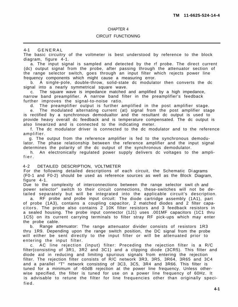
2. The capacity of the diodes varies inversely with signal level. Probe in-put capacity varies from approximately 1pf at 3V to 2.2pf at 10mV. (see figure 4-4)
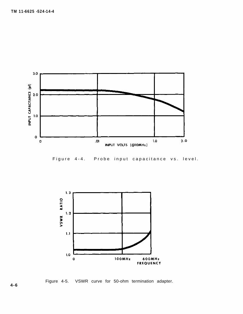
c. Type BNC 50-ohm termination adapter: This is the most widely used terminationwith a VSWR of less than 1.2:1 to 600MHz. It is not recommended for accuratemeasurements above this frequency. (see figure 4-5) The termination has a 5 wattpower rating.
d. High impedance probe tip: This tip allows high impedance direct measure-ments up to 250MHz.
Figure 4-3. Probe input impedance vs. level and frequency.
4-5
TM 11-6625 -524-14-4
4-6
F i g u r e 4 - 4 . P r o b e i n p u t c a p a c i t a n c e v s . l e v e l .
Figure 4-5. VSWR curve for 50-ohm termination adapter.

TM 11-6625-524-14-4
CHAPTER 5
GENERAL SUPPORT MAINTENANCE INSTRUCTIONS
5-1 TOOLS AND TEST EQUIPMENT REQUIRED.a. Tools. No special tools are required.b. Test Equipment. The test equipment required for troubleshooting is listed
below:
Item Name Manufacturer and model number
A1 Osc i l l a t o r Hewlett-Packard 200CDA2 AC voltmeter Hewlett-Packard 400ELA3 Oscilloscope Tekronix 503A4 DC multimeter Millivac 864A
* Equivalent items may be used.
c. Test equipment set-up. A comprehensive test equipment set-up is shown infigure 5-1 below:
5-1
*
Figure 5-1. Maintenance equipment test setup.

TM 11-6625-524-14-4
5-2 CABINET REMOVALShould maintenance require the removal of the voltmeter’s cabinet, the
following procedure should be used:
WARNING
HIGH VOLTAGE capable of causing death is used inside this equip-ment. Use extreme caution when operating or making adjustments in-side the equipment.
(1) Disconnect the voltmeter from the AC power line before removing the cabinet.(2) Removal: Remove the six (6) phillip’s panhead screws from the cabinet’s
lower sides (3 per side) and lift the cabinet straight up to clear the voltmeter.Remove the cabinet’s bottom cover plate by taking out the six (6) phillip’s pan-head screws from the side edges (3 per side) and lifting the plate off.
(3) Shielding: When the voltmeter is to be operated out of its cabinet, adequateshielding will be required to prevent power line and stray AC/RF fields fromradiat ing into the sensit ive input circuits. To shield, place aluminum plates ofsufficient size to cover the chassis top, bottom and two (2) sides; ground allplates to the chassis.
SECTION II. TROUBLESHOOTING
5-3 GENERALa. General. The first procedure in servicing a defective voltmeter is to
sect ional ize the fault . Sect ional izat ion consists of tracing the fault to a printedcircuit board or switch. Once the defective area is located, isolation of the de-fective part is accomplished. Troubleshooting is performed by general support re-pair person.
b. Sectionalization. Listed in (1) through (3) below is a group of testsarranged to help locate the defect.
(1) Visual inspection. When the voltmeter is brought in for repair, remove .the top cover and inspect as follows:
(a) Check to see that all connections and pc boards are properly seated.Repair or replace any connections or leads that are broken or otherwise defective.
(b) Check all switches and controls for ease of operation.(c) Inspect for loose or missing screws.
(2) Operation tests. Operational tests frequently indicate the general locationof trouble. In many instances, the tests will determine the exact nature of thefault. The testing procedures in Chapter 6, paragraphs 6-3, 6-4 and 6-5 provideoperational tests.
(3) Voltage and resistance measurements. Voltage and resistance measurementsare referred to in paragraphs 5-4 through 5-14, as applicable. Several waveformsat critical points are shown in schematic diagrams, F0-1 and F0-2. Use these tolocalize trouble.
c. Servicing. To aid in servicing the voltmeter, major components and testpoints are labeled on the printed circuit boards for reference purposes. All cir-cuit boards and components are readily accessible; all solid-state devices in-cluding the DC modulator are plug-in socket mounted.Should component replacement become necessary, replace with the same type andmanufacture as factory installed. The component should be replaced in the exactmanner and position as the original, otherwise the voltmeter’s operating char-acteristics and accuracies may be altered.
5-2

TM 11-6625-524-14-4
5-4 INOPERATIVEa. Check the AC line power source for line voltage and frequency; it should
agree with that marked on the serial/power plate. Check the 3 wire grounded ACline power cord for continuity. Check the line fuse for continuity and that itagrees with the ratings as factory specified. Use DC multimeter set to 1X ohmsposition for continuity checks.
b. If the pilot light is illuminated but the voltmeter fails to respond to asignal, verify the signal source’s output.
c. Visually check the probe and probe termination for possible damage.d. Try another measuring range to determine if the range being used is inopera-
t i ve .e. Any further troubleshooting wil l require the removal of the voltmeter’s
cabinet. See paragraph 5-2.f . Connect the voltmeter to a 115 volt, 60Hz power source. Set the POWER switch
to ON. Using the DC multimeter set to DC volts, check the power supply voltages andcompare to those as shown on the schematic diagram, figure F0-2.
g. Using the DC multimeter set to DC volts, check the amplifier board for DCsupply voltages and compare to those as shown on the schematic diagram, figure F0-1.
h. Disconnect DC multimeter; disconnect voltmeter from power source.
5-5 ERRACTIC OR INTERMITTENa. Visually check the probe and probe termination for possible cause.b. Try another measuring range to determine if the range being used is inopera-
t i ve .Any further checks will require the removal of the voltmeter’s cabinet. See
paragraph 5-2.d. With the cabinet removed, visually inspect for damaged circuit boards,
broken wires or loose mechanical parts.e. Connect the voltmeter to a 115 volt, 60Hz power source. Set the POWER switch
to ON. Using the DC multimeter set to DC volts, check the power supply voltages andcompare to those as shown on the schematic diagram, figure F0-2.
f . Using the DC multimeter set to DC volts, check the amplifier board forDC supply voltages and compare to those as shown on the schematic diagram, figureF0-1.
9. Disconnect multimeter.
5-6 DC MODULATOR DRIVERa. Verify the DC modulator driver’s ( a 94Hz oscillator) output by measuring
the waveshape at the collector of 3Q2 with the oscilloscope and compare to the valueas shown on the schematic diagram, figure F0-1. If the output is not within speci-f i ca t i ons , try substituting 3Q1 and 3Q2 with known good ones.
b. Check, and if necessary, set the oscillator’s frequency to 94Hz by usingcontrol 3R11.
c. Disconnect oscilloscope.
5-7 POST AMPLIFIER, SYNCHRONOUS DEMODULATOR AND REFERENCE AMPLIFIERThe following procedure is used to check the overall performance of these stages:
a. With the voltmeter properly shielded (see paragraph 5-2) switch to the 0.01Vfull scale range.
b. Locate on the amplifier board link wire 3W3. Unsolder one (1) end of 3W3from 3TP8 and with a short clip lead connect 3TP8 to 3TP10. With another shortclip lead connect 3TP13 to 3TP3.
5-3

TM 11-6625-524-14-4
c. The meter should indicate between 30% and 70% of full scale. If the readingfails to reach 30% or exceeds 70% of full scale, the following procedures may beused to check the applicable stages and components.
d. Readjust amplifier board control (3R53) for a meter reading of 50% of fullscale.
e. Visually check the meter coil for a sticky movement and/or continuity. Ifdefective, replace.
f . Using the DC multimeter set to DC volts, measure the DC voltages at allapplicable transistor stages and compare values to those as shown on schematicdiagram, figure F0-1.
9. The synchronous demodulator’s transistors, 3Q7 and 3Q8, may be checked bysubstitution. Transformers 3T1 and 3T2, if suspected of being faulty, should becarefully unsoldered and removed from the circuit board. Their winding continuityshould be checked by using the DC multimeter set to ohms.
h. Disconnect 3TP10 from 3TP8 and reconnect link wire 3W3 from 3TP8 and 3TP9.Disconnect 3TP3 from 3TP13.
i . Disconnect multimeter.
5-8 NARROW BAND PRE-AMPLIFIERa. With the voltmeter properly shielded (see paragraph 5-2) switch to the 0.001V
full scale range position. Connect the equipment as shown in figure 5-1. Adjust theoscillator frequency to 200KHz and the output level to 1mV as monitored by the ACvoltmeter.
b. Locate on the amplifier board, link 3W3. Unsolder one (1) end of 3W3 from3TP8 .
c. Connect the oscilloscope to 3TP8. Disconnect oscillator from probe. Adjustthe SET REF control for minimum amplitude reading on the oscilloscope; the wave-shape should agree with the value as shown on the schematic diagram, figure F0-1.
d. Reconnect the oscillator to the probe. With 1mV applied to the probe,measure the waveshape. It should agree with the value as shown on the schematic.Improper shielding or zeroing may result in large errors.
e. If this check reveals a faulty condition, the following procedure may beused to check each pre-amplifier stage.
f . Using the DC multimeter set to DC volts, measure the DC voltages at eachstage’s transistor (3Q10, 3Q11 and 3Q12) and compare to those as shown on theschematic diagram, figure F0-1.
.g. With the 1mV signal applied, measure with the oscilloscope the gain of eachstage. A typical gain figure is 10:1. Should the gain check reveal a defectivetransistor, verify its condition by substituting with a known good one.
h. Check the forward and reverse resistances of clipping diode (3DR5). Use theDC multimeter set to ohms.
i . Reconnect 3W3 to 3TP8.j . Disconnect oscilloscope and DC multimeter.
5-9 DC MODULATORa. With the voltmeter properly shielded (see Paragraph 5-2), verify the RANGE
switch is set to the 0.001V full scale range position.b. Verify the DC modulator driver is functioning (see paragraph 5-6).c. To check the modulator’s chopping action, deliberately feed a 30mV, 200KHz
signal to the probe. With the oscilloscope set to a low level sensitivity, observethe waveshape at 3Q9’s gate. If a square-wave is not produced or fails to diminishwhen the signal source is de-energized, the modulator is probably faulty. I ffaulty, replace.
d. Disconnect oscilloscope.
5-4
TM 11-6625-524-14-4
5-10 POWER AND RANGE SWITCHESShould a switch be suspected as being faulty, check the applicable contacts andwiper(s) of the questionable switch sect ion(s) for contact continuity. Also checkthe wiring continuity between the suspected switch section (s) and their circuitconnection (s). Use the DC multimeter set to 1X ohms for continuity checks.
5-11 FEEDBACK, LINEARIZING AND CALIBRATION CONTROL NETWORKa. With the voltmeter properly shielded (see paragraph 5-2) verify that all
l inks are connected to their original circuit board connections.b. Verify the RANGE switch is set to the 0.001V full scale position.c. Disconnect the oscillator from the probe. Adjust the SET REF control (volt-
meter) for a meter reading centered about the SET REF line.d. Reconnect the oscillator to the probe. Connect the oscilloscope to amplifier
board terminal (3TP7). With 1mV applied to the probe, measure the waveshape and com-pare to that as shown on the schematic diagram, figure F0-1. Should the levelgreatly exceed that as shown, the network is probably faulty.
e. The following procedure may be used to troubleshoot the network: f. Check the resistor and thermistor values, diode forward and reverse re-
sistances and the continuity of the network. Use a DC multimeter set to ohms.g. Check the probe for resistance measurements as shown in. Table 5-1. Use the DC
multimeter set to ohms.h. Disconnect the equipment as shown in figure 5-1.
SECTION III MAINTENANCE
5-12 PROBE AND DIODE CARTRIDGEThe probe and diode cartridge are factory sealed and their disassembly is not re-commended. If defective, replace.
NOTE
Warranty on the probe and diode cartridge is void if tampered with.
If the voltmeter fails to respond to RF signals and all other checks of the troubleshooting sections have been made, the probe and/or diode cartridge may be at fault.Use the following procedure to verify the probe and diode cartridge’s condition:With the voltmeter either in its cabinet or properly shielded (see paragraph 5-2)energize and switch to the 0.001V full scale range position. Attach the probe,terminate with the 50-ohm termination adapter but do not connect to a signalsource.Rotate the SET REF control fully clock-wise, a normally operating voltmeter wil lread between 50% and 100% of full scale. Disconnect the probe from the voltmeter,a normal response is for the meter indicator to dri f t off-scale in eitherd i r ec t i on .Switch to the 0.03V full scale range position. The voltmeter should recoverrapidly with the indicator returning to the SET REF position. These tests willverify that the voltmeter is operating normally. The probe and/or probe diodecartr idge is then at fault and should be individual ly tested as fol lows:
Change 1 5-5

TM 11-6625-524-14-4
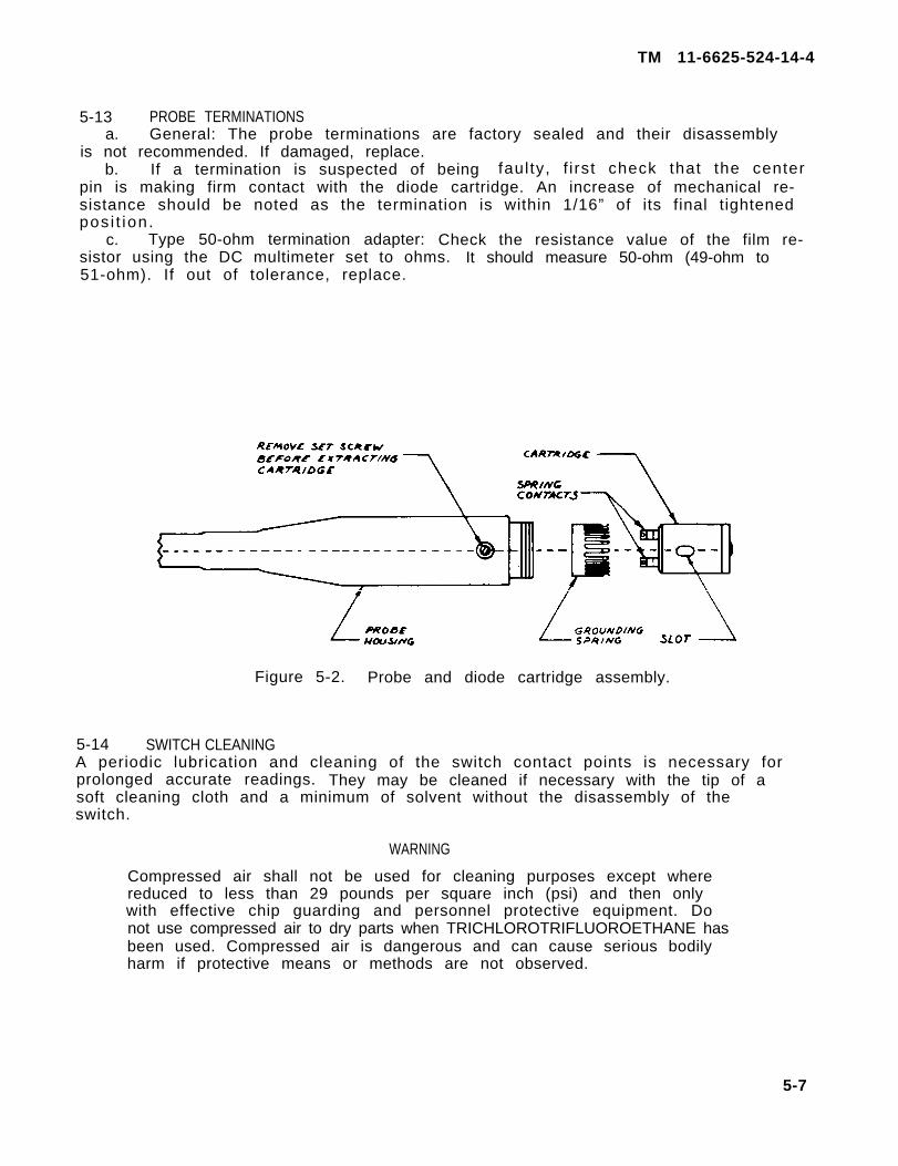
a . D iode Car t r i dge : Diode failure results from excessive Rr, AC or DC in-puts. To test, remove the exposed setscrew on the side of the probe housing,gently slide the cartridge out of the housing (see figure 5-2). Two (2) smallspring contacts will be seen on one (1) end of the cartridge, Care should be ex-ercised, not to damage these contacts,. By placing the DC multimeter, set to ohms,across the contacts, a forward-reverse resistance ratio of approximately 800 timesshould be noted with approximately 5K in the forward direction. Any other readingwould indicate a faulty cartr idge. I f faulty, replace.To replace the diode cartridge, first remove the grounding spring from the probehousing. The spring may be reused only if clean and undamaged. During manufacture,a thin protect ive f i lm of white vasel ine was appl ied to al l si lver-plated surfacesto retard oxidation, Care should be exercised to avoid removal of this film. Ifthe film has been inadvertently removed or if the contacts inside the probe hous-ing have been cleaned, a thin film of white vaseline may be applied to the surface.The cartridge should be carefully inserted into the housing, making certain theslot in the side of the cartridge is aligned with the locking screw hole in theside of the probe housing. The locking screw may now be inserted and tightened,taking care that it properly engages the cartridge slot.Finally, the grounding spring is inserted (note the correct position as shown infigure 5-2). Positioning the spring may be facilitated by gently pushing the cart-ridge all the way into the housing several times. When the spring is in its correctposition, the fingers will be flush with the edge of the probe housing. With alittle thumb pressure, the cartridge should slide smoothly back and forth againstthe spring-loaded socket assembly inside the probe housing. If it binds and doesnot fully return after being depressed, the grounding spring fingers may be curvedexcessively outward. The spring should be removed and the fingers flattened veryslightly by pinching them between the smooth area of a pair of long-nosed pliers.
b. Probe: To test, detach from the voltmeter and remove the diode cartridge.With the DC multimeter set to ohms, perform the following resistance checks andcompare to the values as shown in Table 5-1.
Table 5-1. Probe resistance checks
Location I Resistance
Plug Pin A to Pin BPlug Pin A to Pin CPlug Pin A to Pin DPlug Pin J to Blue DotTerminal in Probe HousingPlug Pin H to Non-Blue DotTerminal in Probe HousingPlug Pin J to Pin HPlug Pins A, J and H toProbe Housing ShellPlug Pins E, F and K toProbe Housing Shell
10K ±5%l00K ±5%500K ±5%
10K ±5%
10K ±5%I n f i n i t y
I n f i n i t y
Less than 1
Any discrepancies in the above probe resistance measurements indicates a faultyprobe. The probe should be replaced.
✩ U . S . G O V E R N M E N T P R I N T I N G O F F I C E 1 9 8 4 - 7 0 7 - 0 0 2
5-6
TM 11-6625-524-14-4
5-13 PROBE TERMINATIONSa. General: The probe terminations are factory sealed and their disassembly
is not recommended. If damaged, replace.b. If a termination is suspected of being faulty, f i rst check that the center
pin is making firm contact with the diode cartridge. An increase of mechanical re-sistance should be noted as the termination is within 1/16” of its final tightenedpos i t ion.
c. Type 50-ohm termination adapter: Check the resistance value of the film re-sistor using the DC multimeter set to ohms. It should measure 50-ohm (49-ohm to51-ohm). If out of tolerance, replace.
Figure 5-2. Probe and diode cartridge assembly.
5-14 SWITCH CLEANINGA periodic lubrication and cleaning of the switch contact points is necessary forprolonged accurate readings. They may be cleaned if necessary with the tip of asoft cleaning cloth and a minimum of solvent without the disassembly of theswitch.
WARNING
Compressed air shall not be used for cleaning purposes except wherereduced to less than 29 pounds per square inch (psi) and then onlywith effective chip guarding and personnel protective equipment. Donot use compressed air to dry parts when TRICHLOROTRIFLUOROETHANE hasbeen used. Compressed air is dangerous and can cause serious bodilyharm if protective means or methods are not observed.
5-7

TM 11-6625-524-14-4
WARNINGAdequate ventilation should be provided while using TRICHLORO-TRIFLUOROETHANE. Prolonged breathing of vapor should be avoided.The solvent should not be used near heat or open flame; the productsof decomposition are toxic and irritating. Since TRICHLOROTRIFLOURE-THANE dissolves natural oils, prolonged contact with skin should beavoided. When necessary, use gloves which the solvent cannot penetrate.If the solvent is taken internally, consult a physician immediately.
CAUTION
The use of TRICHLOROTRIFLOURETHANE on printed circuit boards is notrecommended. Limit cleaning with TRICHLOROTRIFLOURETHANE to metalparts of the case and chassis.
5 -8

TM 11-6625-524-14-4
CHAPTER 6
GENERAL SUPPORT TESTING PROCEDURES
6-1 GENERALThese testing procedures are used to determine the acceptability of repairedequipment. These testing procedures set forth specific requirements that the re-paired equipment must meet before it is returned to the using organization.Perform the testing procedure steps in sequence, do not vary. All tests to be donewith the voltmeter out of its cabinet.Schematic Diagrams F0-1 and F0-2 should be used as reference sources.
6-2 TEST EQUIPMENT REQUIREDThe test equipment required for general support testing is listed below:
Item Name Manufacturer and model number*
A1 Osc i l l a t o r Hewlett-Packard 200CDA2 AC voltmeter Hewlett-Packard 400ELA3 Osc i l l a t o r Tektronix 503A4 DC multimeter M i l l i v a c 8 6 4 AA5 Variable
transformer Superior Electric power stat 116
* Equ i va len t i t ems may be used .
6-3 POWER SUPPLY TESTa. Test equipment.
(1) AC vo l tmeter(2 ) Osc i l l o scope(3) DC mul t imeter(4) Var iab le t ransformer
b. Test connections: Connect the voltmeter (U.U.T.) to the variable transformerwhich is connected to a 115-volt, 60Hz source.
c. Procedure.(1) Set the voltmeter (U.U.T.) to the 3 VOLT full scale range position.(2) Using the AC voltmeter, measure the voltage and adjust the variable
transformer’s output for 115-volt.(3) On the U. U. T., turn POWER switch to ON.(4) Connect the DC multimeter, set to -30V DC, between power supply
board terminals 2TP1 and 2TP2 (2TP2 is the negative side).(5) Measure -13.5V to -15.5V. If not, adjust power supply board control
(2R13) until a reading of -14.5V occurs.(6) Disconnect the DC multimeter, reset to -10V DC and reconnect between
2TP1 and chassis (chassis is the negative side).(7) Measure -5.4V to -6.6V.(8) Disconnect the DC multimeter, reset to +10V DC and reconnect between
2TP2 and chassis (chassis is the negative side).
6-1
TM 11-6625-524-14-4
(9) Measure +7.7V to +9.3V.(10) Disconnect the DC multimeter. Connect the oscilloscope, set to 1
millivolt/centimeter, between 2TP1 and 2TP2.(11) Measure 0.5mV to 0.0mV of ripple.(12) Readjust variable transformer’s output for 103.5V. There should be
no noticeable change in the ripple amplitude.(13) Readjust variable transformer’s output for 126.5V. There should be
no noticeable change in the ripple amplitude.(14) Readjust variable transformer’s output for 115V.
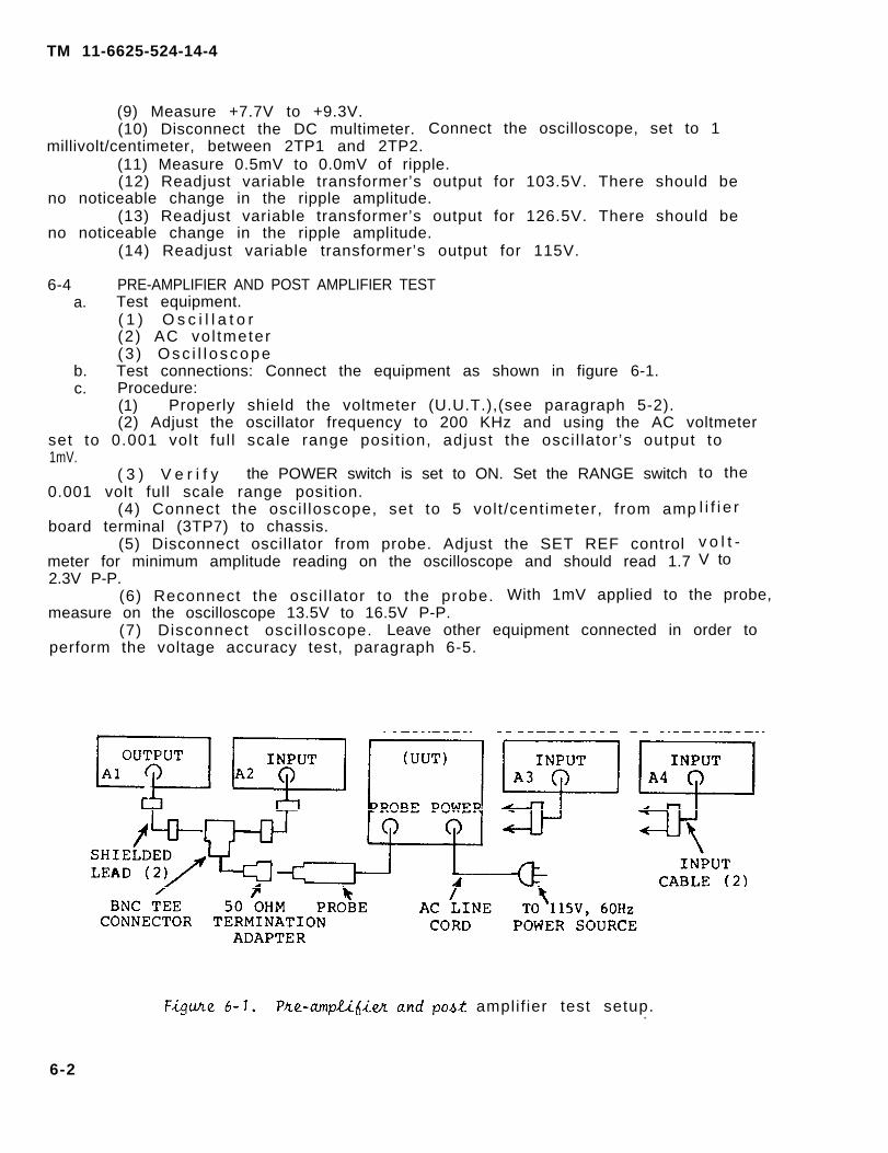
6-4 PRE-AMPLIFIER AND POST AMPLIFIER TESTa. Test equipment.
( 1 ) O s c i l l a t o r(2) AC vo l tmeter(3 ) Osc i l l o scope
b. Test connections: Connect the equipment as shown in figure 6-1.c. Procedure:
(1) Properly shield the voltmeter (U.U.T.),(see paragraph 5-2).(2) Adjust the oscillator frequency to 200 KHz and using the AC voltmeter
set to 0.001 volt ful l scale range posit ion, adjust the osci l lator ’s output to1mV.
( 3 ) V e r i f y the POWER switch is set to ON. Set the RANGE switch0.001 volt full scale range position.
(4) Connect the osci l loscope, set to 5 volt /centimeter, from ampboard terminal (3TP7) to chassis.
(5) Disconnect oscillator from probe. Adjust the SET REF controlmeter for minimum amplitude reading on the oscilloscope and should read 1.72.3V P-P.
to the
l i f i e r
v o l t -V to
(6) Reconnect the osci l lator to the probe. With 1mV applied to the probe,measure on the oscilloscope 13.5V to 16.5V P-P.
(7) Disconnect osci l loscope. Leave other equipment connected in order toperform the voltage accuracy test, paragraph 6-5.
amplif ier test setup..
6-2

TM 11-6625-524-14-4
6-5 VOLTAGE ACCURACY TESTa. Test, equipment.
( 1 ) O s c i l l a t o r(2) AC voltmeter
b. Test connections. As connected from paragraph 6-4.c. Procedure.
(1) On the U. U. T., turn POWER switch to OFF. Adjust the meter’s mechanicalzero to a meter reading of SET REF.
(2) Turn POWER switch to ON.(3) Disconnect oscillator from probe. Adjust the SET REF control (U.U.T.)
for a meter reading centered about the SET REF line.(4) Reconnect oscillator to probe.(5) Using the settings listed below, verify the U.U.T. meter indications
are within their min./max. voltages. Vary the oscillator output to agree with theapplicable AC voltmeter indication. When the U.U.T. is switched to the next rangeposition and for each subsequent range position. ad.iust the SET REF control priorto applying the osci l lator voltage.
Voltmeter (U.U.T.)
RANGE switchposition (VOLTS)
0.0010.0010.0010.0030.0030.0030.010.010.010.030.030.030.10.10.10.30.30.31.01.01.03.03.03.0
Meter indicat ion (volts)Min.
0.0005820.000970.0002910.001940.002010.000970.005820.00970.002910.01940.02910.00970.05820.0970.0290.1940.2910.0970.5820.970.2911.942.910.97
Max.
0.0006180.001030.0003090.002060.003090.001030.006180.01030.003090.02060.03090.01030.06180.1030.03090.2060,3090.1030,6181.030,3092.063.091.03
AC voltmeter indication
( v o l tMin.
0.0005940.000990.0002070.001980.002970.000990.005940.00990.002970.01980.02970.00990.05940.0990.0270,1980.2970.0990.5940,990.2971.982.970.99
Max.
0.0006060.001010.0003030.002020.003030.001010.006060.01010.003030.02020.03030.01010.06060.1010.03030.2020.3030.1010.6061.010.3032.023.031.01
(6) Disconnect equipment as shown in figure 6-1.
6-3/(6-4 blank)


CHAPTER 7
SHIPMENT AND LIMITED STORAGETO PREVENT ENEMY USE
TM 11-6625-524-14-4
AND DEMOLITION
Section I. SHIPMENT AND LIMITED STORAGE
7-1 DISASSEMBLY OF EQUIPMENTDisassemble Voltmeter, Electronic AN/URM-145D as outlined in a, b and c below.
a. Remove the rf probe from the front panel.b. Remove the power cord from the rear panel.c. Set the LINE switch to OFF.
7-2 REPACKAGING FOR SHIPMENT OR LIMITED STORAGEThe exact procedure for repackaging depends on the material available and whetherthe equipment is to be shipped or stored. Adapt the procedures in a, b, and c belowwhenever possible. The information concerning the original packaging (paragraph 2-1)wil l be helpful.
a. Material Requirement. The materials listed in the chart below are requiredfor packaging Voltmeter, Electronic AN/URM-145D. For stock numbers of materials,consult SB 38-100.
Material Quantity
Waterproof paper . . . . . . . . . . . . . . . . . . 6 sq. ft.Waterproof tape . . . . . . . . . . . . . . . . . . . 4 f t .Corrugated cardboard . . . . . . . . . . . . . . 6 sq. ft.Gummed tape . . . . . . . . . . . . . . . . . . . . . . . . 4 f t .Filler material . . . . . . . . . . . . . . . . . . . 3 lbs.
b. Packaging. Pack the cables and adapters in a cardboard carton. Place thecardboard carton on top of the voltmeter. Place pads of filler material on all sur-faces, Place the cushioned unit within a wrap of corrugated cardboard.
c. Packing. Wrap the package in waterproof paper, seal it with waterproof tape,and place it in a corrugated cardboard carton.
Section II. DEMOLITION OF MATERIEL TO PREVENT ENEMY USE
7-3 AUTHORITY FOR DEMOLITIONa. The demolition procedures given in paragraph 7-4 will be used to prevent the
enemy from using or salvaging this equipment. Demolition of the equipment will beaccomplished only upon the order of the Commander.
b. Thorough demolition of equipment will be accomplished through the proceduresoutlined in International Standardization Agreement STANAG 2113, Destruction ofMilitary Technical Equipment. Methods of destruction should damage equipment andessential spare parts so that it will not be possible to restore the equipment toa usable condition in the combat zone either by repair or cannibalization. Re-porting of destruction of equipment is to be done through command channels.
c. If a destruction plan is not provided by higher authority, one should be pre-pared by the organization using the equipment. In this plan, personnel should beassigned specific destruction tasks, but all personnel in the using organizationshould be familiar with all aspects of the complete destruction plan. The plan mustbe adequate and easily carried out in the field and must provide for as complete adestruction as avilable time, equipment and personnel will permit. Because the
7-1
TM 11-6625-524-14-4
time required for complete destruction may not always be available, the destructionplan must establish priorities so that essential parts of the equipments will bedestroyed in the order of their importance. Systematic destruction of the sameimportant units of equipment of a given type will prevent the enemy from learningthe important features of the equipment or assembling a complete equipment ofcannibalization of partially destroyed equipment. Adequate destruction of some unitof equipment should always be accomplished rather than partial destruction of allun i ts . The method listed in paragraph 8-4 which is to be used depends on the timeavailable for destruction.
7-4 METHODS OF DESTRUCTIONa. Destruction Priori ty. STANAG 2113 outlines the general priorities for any
equipment which is to be destroyed.b. Smash, Smash the controls, resistors, capacitors, switches and other in-
ter ior par ts .c. Cut. Cut the cords, cables, and wiring; use axes, handaxes, or machetes.
WARNING
Be extremely careful with explosives and incendiary devices. Use theseitems only when the need is urgent.
d. Burn. Burn the cords, wiring, technical manuals and components.e. Bend. Bend the panels, casing, and connectors.f . Explosives. Use explosives only as necessary.9. Disposal. Burn or scatter the destroyed parts in slit trenches, fox-holes or other holes, or throw them into nearby streams.
7-2

TM 11-6625-524-14-4
APPENDIX A
REFERENCES
DA Pam 310-1 Consolidated Index of ArmyPublications and Blank Forms
SB 38–100 Preservation, Packaging, Packingand Marking Supplies and Equipmentused by the Army.
TB 43-0118 Field Instruct ions for Paint ingand Preserving ElectronicsCommand Equipment Including Camo–flage Pattern Paint ing of Electr icalEquipment Shelters.
TB 43-180
TB 385-4
TM 11-6625-320-12
TM 11–6625-573-14
TM 11-6625-2658-14
TM 11-6625–2725-14-4
TM 38-750
Calibration Requirements for theMaintenance of Army Material,
Safety Precautions for Maintenanceof Electrical/ Electronics Equipment.
Operator’s and OrganizationalMaintenance Manual Voltmeter,Meter ME-30A/U and Voltmeters, Elect-ronic ME-30B/U, ME-30C/U, andME-30E/U.
Operator’s, Organizational, DirectSupport and General SupportMaintenance Manual for GeneratorSignal AN/GRM-50 (FSN 6625-868-8353).
Operator’s, Organizational, DirectSupport, and General SupportMaintenance Manual for OscilloscopeAN/USM-281C (NSN 6625-00-106-9622)
Operator’s, Organizational, DirectSupport, and General SupportMaintenance Manual Including RepairParts and Special Tools List(Including Depot Maintenance RepairParts and Special Tools) for GeneratorSignal AN/URM-127A. (NSN 6625-00-783-5965)
The Army Maintenance ManagementSystem (TAMMS)
A-1
TM 11-6625-524-14-4
TM 740-90–1
TM 750-244-2
Administrative Storage of Equipment
Procedures for Destruction ofElectronics Material to PreventEnemy Use (Electronic Command).
A-2

TM 11-6625-524-14-4
APPENDIX B
COMPONENTS OF END ITEM LIST
Section I. INTRODUCTION
B-1. ScopeThis appendix lists integral components of AN/URM-145D to help you inventoryitems required for safe and efficient operation.
B-2. GeneralThis Components of End Item List is divided into the following sections:
a. Section II. Integral Components of End Item. These items comprisethe AN/URM-145D and must acccmpany it whenever it is transferred or turned in.The i l lustrat ions wil l help you identi fy these i tens.
b. Sect ion I I I . Basic Issue Items (Not Applicable).
B-3. Explanation of Columnsa. l l l u s t r a t i o n . This column is divided as follows:
(1) Figure number. Indicates the figure number of the illustrationon which the item is shown.
(2) Item number. The number used to identify item called out ini l l u s t r a t i o n .
b. National Stock Number. Indicates the National stock number assignedto the item and which will be used for requisitioning.
c . Description. Indicates the Federal item name and, if required, a min-imum description to identify the item. The part number indicates the primarynumber used by the manufacturer, which controls the design and characteristicsof the item by means of its engineering drawings, specifications, standards,and inspection requirements to identify an item or range of item. Followingthe part number, the Federal Supply Code for Manufacturers (FSCM) is shown inparentheses.
d. Location. The physical location of each item listed is given in thiscolumn. The lists are designed to inventory all items in one area of themajor item before moving on to an adjacent area.
e. Usable on Code. (Not Applicable).f. Quantity Required (Qty Reqd). This column lists the quantity of each
item required for a complete major itcm.g . Quan t i t y . This column is left blank for use during an inventory. Under
the Rcvd column, list the quantity you actually received on your major item.The date columns are for your use when you inventory the major item, at a laterdate such as for shipment to another site.
(Next printed page is B-3)
B-1/(B-2 blank)


TM 11-6625-524-14-4
SECTION II INTEGRAL COMPONENTS OF END ITEM
SECTION I I I BASIC ISSUE ITEMS
(1) (2)ILLUSTRATION NATIONAL
A B STOCKFIG ITEM NUMBER
No No
2-1
2-1
2-1
2-1
2-1
2-1
3-2
A
B
c
D
E
F
2
5625-01-119–7271
5150-01-004-8773
6625-00-975-1292
5935-00-637-1842
6625-90-223-1930
6625-00-470-3717
5920-90-235-8362
(3)DESCRIPTION
(FSCM)
Voltmeter,E lect ron icME-247D/U(MV-828A) 85711
AC Line PowerCord(800-5121) 85711
Probe SubassemblyMX-10334/URM(900-2002) 85711
DC OutputPhone Plug(60) 82389
Probe, SubassemblyMX-10333/URM 85711
Lead, TestMX-10334(900-2000B) 85711
Fuse 0.3 AS/B 75915
TM 11-6625-524-14-4
(4)LOCATION
Basic Issue Items (Not applicable)
REQDON
CODE
1
1
1
1
1
1
1
B-3/(B-4 blank)


TM 11-6625-524-14-4
APPENDIX D
MAINTENANCE ALLOCATION
SECTION I. INTRODUCTION
D1 . General
This appendix provides a summary of the maintenance operations for theVoltmeter AN/URM-145D. It authorizes categories of maintenance forspecific maintenance functions on repairable items and components and thetools and equipment required to perform each function. This appendix maybe used as an aid in planning maintenance operations.
D-2 . Maintenance Function
Maintenance functions will be limited to and defined as follows:
a. Inspect. To determine the serviceability of an item by comparingits physical, mechanical and/or electrical characteristics with establishedstandards through examination.
b. Test. To veri fy serviceabi l i ty and to detect incipient fai lure bymeasuring the mechanical or electrical characteristics of an item andcomparing those characteristics with prescribed standards.
c. Service. Operations required periodically to keep an item in properoperating condition, i.e., to clean (decontaminate), to preserve, to drain,to paint, or to replenish fuel, lubricants, hydraulic fluids, or compressedair supplies.
d. Adjust. To maintain, within prescribed limits, by bringing intoproper or exact position, or by setting the operating characteristics tothe specified parameters.
e. Align. To adjust specified variable elements of an item to bringabout optimum or desired performance.
f . Calibrate. To determine and cause corrections to be made or to beadjusted on instruments or test measuring and diagnostic equipments used inprecision measurement.
9. I n s t a l l . The act of emplacing, seating or fixing into position anitem, part, module (component or assembly) in a manner to allow the properfunctioning of the equipment or system.
h. Replace. The act of substituting a serviceable like type part,subassembly or module (component or assembly) for an unserviceablecounterpart.
D-1
TM 11-6625-524-14-4
i . Repair, The application of maintenance services (inspect, test,service, adjust, al ign, cal ibrate, replace) or other maintenance act(welding, grinding, r ivet ing, straightening, facing, remachining orresurfacing) to restore serviceability to an item by correcting specdamage, fault, malfunction, or failure in part, subassembly, module(component or assembly), end item or system.
j . Overhaul. That maintenance effort (service/action) necessarrestore an item to a completely serviceable/operational condition as
ons
f i c
to
prescribed by maintenance standards (i.e., DMWR) in appropriate technicalpublications. Overhaul is normally the highest degree of maintenance per-formed by the Army. Overhaul does not normally return an item to like newcondition.
k. Rebuild. Consists of those services/actions necessary for therestoration of unserviceable equipment to a like new condition in accordancewith original manufacturing standards. Rebuild is the highest degree ofmateriel maintenance applied to Army equipment. The rebuild operationincludes the act of returning to zero those age measurements (hours, miles,etc.) considered in classifying Army equipments/components.
D-3. Column Entries
a. Column 1, Group Number. Column 1 lists group numbers, the purposeof which is to identify components, assemblies, subassemblies and moduleswith the next higher assembly.
b. Column 2, Component/Assembly. Column 2 contains the noun names ofcomponents, assemblies, subassemblies and modules for which maintenance isauthorized.
c. Column 3, Maintenance Functions. Column 3 lists the functions tobe performed on the item listed in column 2. When items are listed withoutmaintenance functions, it is solely for purpose of having the group numbersin the MAC and RPSTL coincide.
d. Column 4, Maintenance Category. Column 4 specifies, by the listingof a “work time” figure in the appropriate subcolumn(s), the lowest level ofmaintenance authorized to perform the function listed in column 3. Thisfigure represents the active time required to perform that maintenancefunction at the indicated category of maintenance. If the number or com-plexity of the tasks within the listed maintenance function vary atdifferent categories, appropriate “work time” figures will be shown foreach category. The number of task-hours specified by the “work time”figure represents the average time required to restore an item (assembly,subassembly, component, module, end item or system) to a serviceablecondit ion under typical f ield operating condit ions. This time includespreparation time, troubleshooting time, and quality assurance/qualitycontrol time in addition to the time required to perform the specific tasksidentified for the maintenance functions authorized in the Maintenance
D-2

TM 11-6625-524-14-4
Allocation Chart. Subcolumns of column 4 are as follows:
C - Operator/Crew
0 - Organizational
F - Direct Support
H - General Support
D - Depot
e. Column 5, Tools and Equipment. Column 5 specifies by code, thosecommon tool sets (not individual tools) and special tools, test and supportequipment required to perform the designated function.
f . Column 6, Remarks. Column 6 contains an alphabetic code which leadsto the remark in section IV, Remarks, which is pertinent to the itemopposite the particular code.
D-4. Tool and Test Equipment Requirements (Sect. III).
a. Tool or Test Equipment Reference Code. The numbers in this columncoincide with the numbers used in the tools and equipment column of the MAC.The numbers indicate the applicable tool or test equipment for the main-tenance functions.
b. Maintenance Category. The codes in this column indicate themaintenance category allocated the tool or test equipment.
c. Nomenclature. This column lists the noun name amd nomenclature ofthe tools and test equipment required to perform the maintenance functions.
d. National/NATO Stock Number. This column lists the National/NATOstock number of the specific tool or test equipment.
e. Tool Number. This the tool followed by theparentheses.
D-5. Remarks (Sect. IV).
a. Reference Code.II, column 6.
column lists the manufacturer’s part number ofFederal Supply Code for manufacturers (5-digit) in
This code refers to the appropriate item in section
b. Remarks. This column provides the required explanatory informationnecessary to clarify items appearing in section II.
D-3 (D–4 blank)


TM 11 -6625-524 -14 -4
SECTION II MAINTENANCE ALLOCATION CHARTFOR
VOLTMETER, ELECTRONIC AN/URM-145D
,(1) (2) (3) (4)
GROUP MAINTENANCE C4TEGORY (5)COMPONENT/ASSEMBLY (6)
MAlNTENANCENUMBER TOOLS REMARKSFUNCTION c o F H D AND
EQPT.
00 VOLTMETER, ELECTRONICAN/URM-145D
01 VOLTMETER, ELECTRONIC Inspect 0.2 Visua l AME-247D Service 0.5 9 B
Repair 0.2 9 CInspect 0 .3 Visua l DReplace 0.2 8 ECal ibrate 0.6 1 thru 4,7 FA l i gn 0.2 1,5 GRepair 0.5 8
0101 POWER SUPPLY Test 0.4 1,2,5 HRepair 0.8 1 thru 8Ad-just 0.1 1,5 I
0102 PREAMPLIFIER AND Test 0.6 1,2 ,4 ,6 JAMPLIFIER Repair 0 .8 1 thru 8
Adjust 0.2 1,2,4
D-5

TM 11-6625-524-14-4
SECTION I I I TOOL AND TEST EQUIPMENT REQUIREMENTSFOR
VOLTMETER, ELECTRONIC AN\URM-145D
TOOL OR TEST MAINTENANCEEQUIPMENT NOMENCLATURE NATIONAL/NAT0 TOOLCATEGORYREF CODE STOCK NUMBER NUMBER
1 H VOLTMETER, ELECTRONIC ME-30/U 6625-00-643-1670 HP334A
2 H OSCILLOSCOPE, AN/USM-281C 6625-00-106-9622 TEK5440
3 H GENERATOR, SIGNAL AN/GRM-50 6625-00-003-3238 HP8640B
4 H OSCILLATOR, AN/URM-127A 6625-00-783-5722 HP652A
5 H TRANSFORMER, VARIABLE, CN-16/U 5950-00-688-5722 W010MT3
6 H ADAPTER, MILLIVAC #900-2100
7 H CABLE ASSEMBLY, RF-CG-409H/U 5995-00-070-8747(2 required)
8 H TOOL KIT, ELECTRONIC EQUIPMENT 5180-00-605-0079TK-100/G
9 0 TOOLS AVAILABLE TO THE ORGANI-ZATION BECAUSE OF THEASSIGNED MISSION.
.
D-6

TM 11-6625-524-14-4
SECTION IV. REMARKS
VOLTMETER, ELECTRONIC AN/URM-145D
REFERENCECODE REMARKS
_
A External receptacles, meter glass, knobs, controls, andswitches for proper action, cables for cuts, cracks orfraying, external hardware, rust and corrosion.
B Clean exterior surfaces, remove dirt, grease and fungus, rustand corrosion. Apply touchup paint.
C Repair through replacement of burned out fuse and defectivea knobs.
D Loose or missing hardware; check switches, controls, con-nections and printed circuit boards.
EI
Replace missing or defective hardware.
F Operational checks to localize troubles. Voltage andResistance measurements, Voltage accuracy tests.
G Voltage adjustments.
HI
Voltage and ripple tests.
II
Output voltage adjustments.
J Noise, voltage and waveshape tests.
I
D-7/(D-8 blank)
✩ U.S. GOVERNNENT PRINTING PRINTING OFFICE: 1982-505-028:111


TM 11-6625-524-14-4
SCHEMATIC DIAGRAM
ASSEMBLYEL6625-524-14-TM-13
FO-1
OF AMPLIFIER BOARD

TM 11-6625-524-14-4
FO-2
SCHEMATIC DIAGRAM
EL6625-524-14-TM-14
BOARD ASSEMBLY,RANGE SWITCH ANDPOWER SWITCH
OF POWER SUPPLY


By Order of the Secretary of the Army:
Official:ROBERT M. JOYCE
Brigadier General, United States ArmyThe Adjutant General
DISTRIBUTION:
To be distributed in accordance with special list.
EDWARD C. MEYERGeneraI, United States Army
Chief of Staff


051232-0000

This fine document...
Was brought to you by me:
Liberated Manuals -- free army and government manuals
Why do I do it? I am tired of sleazy CD-ROM sellers, who take publicly available information, slap “watermarks” and other junk on it, and sell it. Those masters of search engine manipulation make sure that their sites that sell free information, come up first in search engines. They did not create it... They did not even scan it... Why should they get your money? Why are not letting you give those free manuals to your friends?
I am setting this document FREE. This document was made by the US Government and is NOT protected by Copyright. Feel free to share, republish, sell and so on.
I am not asking you for donations, fees or handouts. If you can, please provide a link to liberatedmanuals.com, so that free manuals come up first in search engines:
<A HREF=http://www.liberatedmanuals.com/>Free Military and Government Manuals</A>
– SincerelyIgor Chudovhttp://igor.chudov.com/
– Chicago Machinery Movers