Embed Size (px)
Citation preview

GRAND TOURING 500/583SUMMIT 500/x 670MX Z 440/500/670 H.O.FORMULA Z 500/583/670FORMULA DELUXE 500 LC/583/670SKANDIC WT/SWT/WT LC484 200 003
Volume 2

1999Shop Manual
VOLUME 2
MX Z 440/500/670 HO/670 HO T.H.FORMULA Z 500/DELUXE 500 LC/Z 583/
DELUXE 583/Z 670/DELUXE 670SUMMIT 500/X 670
GRAND TOURING 500/583SKANDIC WT/SWT/WT LC

Legal deposit:
National Library of Quebec4th trimester 1998National Library of Canada1998
All rights reserved. No parts of this manual may be reproduced in anyform without the prior written permission of Bombardier Inc.©Bombardier Inc. 1998
Technical Publications Bombardier Inc.Valcourt (Quebec) Canada
Printed in Canada®*Registered trademarks of Bombardier Inc.
This document contains the trademarks of the following companies:Kimtowels® is a trademark of Kimberly-ClarkLoctite® is a trademark of Loctite CorporationMetton® is a trademark of Hercules Inc.Molykote® is a trademark of Dow Corning CorporationSilastic® is a trademark of Dow Corning CorporationSnap-on® is a trademark of Snap-on Tools CorporationVersilube® is a trademark of General Electric CompanySupertaniumTM is a trademark of Premier Industrial Corporation
I
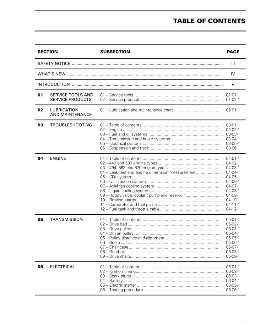
SECTION SUBSECTION PAGE
SAFETY NOTICE .................................................................................................................................. III
WHAT’S NEW ....................................................................................................................................... IV
INTRODUCTION .................................................................................................................................. V
01 SERVICE TOOLS ANDSERVICE PRODUCTS
01 – Service tools............................................................................. 01-01-102 – Service products....................................................................... 01-02-1
02 LUBRICATIONAND MAINTENANCE
01 – Lubrication and maintenance chart .......................................... 02-01-1
03 TROUBLESHOOTING 01 – Table of contents...................................................................... 03-01-102 – Engine ...................................................................................... 03-02-103 – Fuel and oil systems................................................................. 03-03-104 – Transmission and brake systems............................................. 03-04-105 – Electrical system ...................................................................... 03-05-106 – Suspension and track ............................................................... 03-06-1
04 ENGINE 01 – Table of contents...................................................................... 04-01-102 – 443 and 503 engine types ........................................................ 04-02-103 – 494, 583 and 670 engine types ................................................ 04-03-104 – Leak test and engine dimension measurement ....................... 04-04-105 – CDI system............................................................................... 04-05-106 – Oil injection system.................................................................. 04-06-107 – Axial fan cooling system........................................................... 04-07-108 – Liquid cooling system............................................................... 04-08-109 – Rotary valve, coolant pump and reservoir ................................ 04-09-110 – Rewind starter.......................................................................... 04-10-111 – Carburetor and fuel pump ........................................................ 04-11-112 – Fuel tank and throttle cable ...................................................... 04-12-1
05 TRANSMISSION 01 – Table of contents...................................................................... 05-01-102 – Drive belt .................................................................................. 05-02-103 – Drive pulley............................................................................... 05-03-104 – Driven pulley............................................................................. 05-04-105 – Pulley distance and alignment.................................................. 05-05-106 – Brake ........................................................................................ 05-06-107 – Chaincase................................................................................. 05-07-108 – Gearbox .................................................................................... 05-08-109 – Drive chain................................................................................ 05-09-1
06 ELECTRICAL 01 – Table of contents...................................................................... 06-01-102 – Ignition timing........................................................................... 06-02-103 – Spark plugs............................................................................... 06-03-104 – Battery...................................................................................... 06-04-105 – Electric starter .......................................................................... 06-05-106 – Testing procedure .................................................................... 06-06-1
TABLE OF CONTENTS

II
07 REAR SUSPENSION 01 – Table of contents ..................................................................... 07-01-102 – SC-10 suspensions (all versions).............................................. 07-02-103 – ARM suspension...................................................................... 07-03-104 – Skandic WT suspension........................................................... 07-04-105 – Drive axle ................................................................................. 07-05-106 – Track ........................................................................................ 07-06-1
08 STEERING/FRONT SUSPENSION
01 – Table of contents ..................................................................... 08-01-102 – Steering system....................................................................... 08-02-103 – Suspension and ski system ..................................................... 08-03-1
09 BODY/FRAME 01 – Table of contents ..................................................................... 09-01-102 – Body......................................................................................... 09-02-103 – Frame....................................................................................... 09-03-1
10 TECHNICAL DATA 01 – SI metric information guide...................................................... 10-01-102 – Engines .................................................................................... 10-02-103 – Vehicles.................................................................................... 10-03-104 – Technical data legends............................................................. 10-04-1
11 WIRING DIAGRAMS 01 – Wiring diagrams....................................................................... 11-01-1
SECTION SUBSECTION PAGE
TABLE OF CONTENTS

III
SAFETY NOTICE 0This manual has been prepared as a guide to correctly service and repair some 1999 Ski-Doo snowmo-biles. See model list on next page.This edition was primarily published to be used by snowmobile mechanics who are already familiar withall service procedures relating to Bombardier made snowmobiles.Please note that the instructions will apply only if proper hand tools and special service tools are used.This Shop Manual uses technical terms which may be slightly different from the ones used in the PartsCatalog.It is understood that this manual may be translated into another language. In the event of any discrepan-cy, the English version shall prevail.The content depicts parts and/or procedures applicable to the particular product at its time of manufac-ture. It does not include dealer modifications, whether authorized or not by Bombardier, after manufac-turing the product.In addition, the sole purpose of the illustrations throughout the manual, is to assist identification of thegeneral configuration of the parts. They are not to be interpreted as technical drawings or exact replicasof the parts.The use of Bombardier parts is most strongly recommended when considering replacement of any com-ponent. Dealer and/or distributor assistance should be sought in case of doubt.The engines and the corresponding components identified in this document should not be utilized onproduct(s) other than those mentioned in this document.Torque wrench tightening specifications must be strictly adhered to. Locking devices (ex.: locking tab,elastic stop nut, etc.) must be installed or replaced with new ones, where specified. If the efficiency ofa locking device is impaired, it must be renewed.This manual emphasizes particular information denoted by the wording and symbols:
NOTE: Indicates supplementary information needed to fully complete an instruction.Although the mere reading of such information does not eliminate the hazard, your understanding of theinformation will promote its correct use. Always use common shop safety practice.This information relates to the preparation and use of Bombardier snowmobiles and has been utilizedsafely and effectively by Bombardier Inc. However, Bombardier Inc. disclaims liability for all damagesand/or injuries resulting from the improper use of the contents. We strongly recommend that any servic-es be carried out and/or verified by a highly skilled professional mechanic. It is understood that certainmodifications may render use of the vehicle illegal under existing federal, provincial and state regulations.
◆ WARNING
Identifies an instruction which, if not followed, could cause serious personal injury includingpossibility of death.
- CAUTION
Denotes an instruction which, if not followed, could severely damage vehicle components.
SAFETY NOTICE

IV
WHAT’S NEW 0SERVICE TOOLS AND SERVICE PRODUCTS 01• Complete list of SKI-DOO service tools.
443 AND 503 ENGINES TYPES 04-02• Lithium grease on crankshaft seal lip is replaced by Molykote 111.
494, 583 AND 670 ENGINES TYPES 04-03• Lithium grease on crankshaft seal lip is replaced by Molykote 111.
OIL INJECTION SYSTEM 04-06• Procedure for leak test.
AXIAL FAN COOLING SYSTEM 04-07• Procedures for checking belt deflection and to replace it.
SC-10 SUSPENSION (ALL VERSIONS) 07-02• Wear limit of slider shoe is now indicated by a line.
ARM SUSPENSION 07-03• Wear limit of slider shoe is now indicated by a line.
WHAT’S NEW

V
INTRODUCTION 0This Shop Manual Volume 2 covers the following Bombardier made 1999 snowmobiles:
*Trademarks of Bombardier Inc.
MODELS MODELNUMBER
MX Z 440 (Canada)............................. 1409
MX Z 440 (Canada)............................. 1448
MX Z 440 (U.S.) .................................. 1410
MX Z 440 (U.S.) .................................. 1449
MX Z 440 (Europe) ............................. 1411
MX Z 500 (Canada)............................. 1412
MX Z 500 (Canada)............................. 1450
MX Z 500 (U.S.) .................................. 1413
MX Z 500 (U.S.) .................................. 1451
MX Z 500 (Europe) ............................. 1414
MX Z 670 HO (Canada) ...................... 1415
MX Z 670 HO (Canada) ...................... 1452
MX Z 670 HO T.H. (Canada)............... 1465
MX Z 670 HO (U.S.) ............................ 1416
MX Z 670 HO (U.S.) ............................ 1453
MX Z 670 HO T.H. (U.S.) .................... 1466
MX Z 670 HO (Europe)....................... 1417
FORMULA* Z 500 (Canada)............... 1388
FORMULA* Z 500 (U.S.) .................... 1389
FORMULA* Z 500 (Europe) ............... 1458
FORMULA* DELUXE 500 LC(Canada).............................................. 1377
FORMULA* DELUXE 500 LC (U.S.)... 1378
FORMULA* DELUXE 500 LC(Europe) .............................................. 1379
FORMULA* DELUXE 583 (Canada) .. 1380
MODELS MODELNUMBER
FORMULA* DELUXE 583 (U.S.)........ 1381
FORMULA* Z 583 (Canada) .............. 1391
FORMULA* Z 583 (U.S.).................... 1392
FORMULA* Z 670 (Canada) .............. 1393
FORMULA* Z 670 (U.S.).................... 1394
FORMULA* Z 670 (Europe)............... 1395
FORMULA DELUXE 670 (Canada) .... 1382
FORMULA DELUXE 670 (U.S.).......... 1383
SUMMIT 500 (Canada) ...................... 1403
SUMMIT 500 (U.S.)............................ 1404
SUMMIT 500 (Europe)....................... 1405
SUMMIT X 670 (Canada)................... 1406
SUMMIT X 670 (U.S.) ........................ 1407
SUMMIT X 670 (Europe) ................... 1408
GRAND TOURING 500 (Canada) ...... 1367
GRAND TOURING 500 (U.S.) ............ 1368
GRAND TOURING 500 (Europe) ....... 1369
GRAND TOURING 583 (Canada) ...... 1370
GRAND TOURING 583 (U.S.) ............ 1371
GRAND TOURING 583 (Europe) ....... 1372
SKANDIC* WT (Canada) ................... 1429
SKANDIC* WT (U.S.) ......................... 1430
SKANDIC* SWT (Canada) ................. 1431
SKANDIC* SWT (U.S.)....................... 1432
SKANDIC* WT LC (Canada) .............. 1427
SKANDIC* WT LC (U.S.).................... 1428
INTRODUCTION

VI
MX Z 440/500/670 HO/670 HO T.H.Formula Z 500/DELUXE 500 LC/Z 583Formula DELUXE 583/Z 670/DELUXE 670Summit 500/X 670Grand Touring 500/583
These are S-Series models.
TYPICAL — S-SERIES
Skandic WTSkandic SWTSkandic WT LC
These are Skandic WT Series models.
TYPICAL — SKANDIC WT SERIES
VEHICLE SERIAL NUMBERVehicle Serial Number Location
TYPICAL1. Vehicle serial number
Serial Number Meaning
ENGINE SERIAL NUMBEREngine Serial Number LocationFan-Cooled Engines
TYPICAL — FAN-COOLED ENGINES1. Engine serial number
A03A0LA
A29A03A
A03H2AA1
A00A0DA
Model no. Vehicle no.
0000 00000
A03A0BA
1
INTRODUCTION

VII
Liquid-Cooled Engines
TYPICAL — LIQUID-COOLED ENGINES1. Engine serial number
ARRANGEMENT OF THE MANUALThe manual is divided into 11 major sections:01 SERVICE TOOLS AND SERVICE PRODUCTS02 LUBRICATION AND MAINTENANCE03 TROUBLESHOOTING04 ENGINE05 TRANSMISSION06 ELECTRICAL07 REAR SUSPENSION08 STEERING/FRONT SUSPENSION09 BODY/FRAME10 TECHNICAL DATA11 WIRING DIAGRAMSEach section is divided in various subsections,and again, each subsection has one or more divi-sion.
A00C1QA
1
INTRODUCTION

VIII
LIST OF ABBREVIATIONS USED IN THIS MANUAL
A ampere
amp ampere
A•h ampere-hour
AC alternate current
ACM acceleration and control modulator
ARM advance ride management
BDC bottom dead center
BTDC before top dead denter
°C degree Celsius
CDI capacitor discharge ignition
CTR center
cm centimeter
cm² square centimeter
cm³ cubic centimeter
DC direct current
DPM digital performance management
DSA direct shock action
°F degree Fahrenheit
FC fan cooled
fl. oz fluid ounce
ft foot
GRD ground
H.A.C. high altitude compensator
hal. halogen
HI high
imp. oz imperial ounce
in inch
in² square inch
in³ cubic inch
k kilo (thousand)
kg kilogram
km/h kilometer per hour
kPa Kilopascal
L liter
lb pound
lbf pound (force)
lbf/in² pound per square inch
LH left hand
LO low
LT long track
m meter
MAG magneto
Max. maximum
Min. minimum
mL milliliter
mm millimeter
MPEM multi-purpose electronic module
MPH mile per hour
N newton
N.A. not applicable
no. number
00.0 continuity
0.L overload (open circuit)
O.D. outside diameter
OPT optional
oz ounce
P/N part number
PSI pound per square inch
PTO power take off
R rectangular
RH right hand
RAVE rotax adjustable variable exhaust
RPM revolution per minute
RMS root mean square
RRIM reinforced reaction injection molding
Sp. Gr. specific gravity
ST semi-trapez
TDC top dead center
TRA total range adjustable
U.S. oz ounce (United States)
V volt
Vac volt (alternative current)
INTRODUCTION
IX
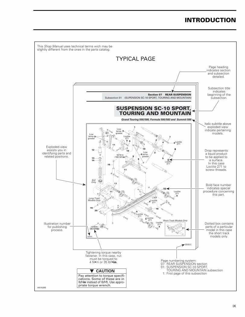
Section 07 REAR SUSPENSIONSubsection 01 (SUPENSION SC-10 SPORT, TOURING AND MOUNTAIN)
SUSPENSION SC-10 SPORT,TOURING AND MOUNTAIN
Grand Touring 500/580, Formula 500/583 and Summit 500
07-01-1
A03F24S
Short Track Models Only
Long TrackModels Only
SLEOnly
Loctite271
Loctite271
Loctite271
Loctite271
Loctite271
Loctite271
Loctite271
Loctite271
Lowtemp.grease
6
5
6
7
4
3
2
1
6
19
Lowtemp.grease
89
16
Lowtemp.grease
11
12
1314
15
11
11
11
1620
18
10
17
11
18 N�m(160 lbf�in)
4 N�m(35 lbf�in)
Page headingindicates sectionand subsection
detailed.
Bold face numberindicates special
procedure concerningthis part.
Tightening torque nearbyfastener. In this case, nut
must be torqued to4 N�m or 35 lbf�in.
This Shop Manual uses technical terms wich may beslightly different from the ones in the parts catalog.
Exploded viewassists you in
identifying parts andrelated positions.
TYPICAL PAGE
A01A28S
Illustration numberfor publishing
process.
Subsection titleindicates
beginning of thesubsection.
Drop representsa liquid productto be applied to
a surface.In this case
Loctite 271 toscrew threads.
Dotted box containsparts of a particularmodel in this case
the short trackmodels only.
Page numbering system:07: REAR SUSPENSION section01: SUSPENSION SC-10 SPORT,
TOURING AND MOUNTAIN subsection 1: First page of this subsection
Italic subtitle aboveexploded view
indicate pertainingmodels.
Pay attention to torque specifi-cations. Some of these are inlbf�in instead of lbf�ft. Use appro-priate torque wrench.
CAUTIONt
INTRODUCTION

X
05-03-5
A16D0IA
1
2
A
1
Turn puller handle and sliding half at once to extractthe bushing.
INSTALLATIONCountershaft
F-Series and S-Series Only
Should installation procedure be required, referto BRAKE 05-05 then look for Brake Disc andCountershaft Bearing Adjustment.
IMPORTANT: Large bushing retaining screws andwashers must be removed before small bushinginstallation.Coat bushing outside diameter with Loctite 609(P/N 413 703 100).Install bushing as following photo.
All Models
Check end play of driven pulley on countershaft bypushing pulley towards outer housing so that the innershims ( P/N 504 108 200) contact it. Measure end playat the mounting screw end between shim(s) and puley.See illustration.
TYPICAL � TOP VIEW
1. Shim (P/N 504 108 200) (as required)2. ContactA. 0 to 1 mm (0 to 3/64 in)
Torque retaining screw no. 13 to 25 N�m (18 lbf�ft).
ADJUSTMENTRefer to PULLEY DISTANCE AND ALIGNMENT 05-04to adjust pulley distance. Adjust drive belt heightbetween pulley halves to obtain specified beltdeflection.
Reinstall the pulley on the countershaft by rever-sing the removal procedure.
A03D1YA
529 031 300
529 031 200
A03D1ZA
529 031 300
529 031 200
Cam
Coat cam no. 18 interior with anti-seize lubricant.
ASSEMBLYCame Slider Shoe
Section 05 TRANSMISSIONSubsection 03 (DRIVEN PULLEY)
When replacing slider shoes no. 4, always install a newset (3 shoes) to maintain equal pressure on the cam.
Assemble driven pulley components by reversingthe disassembly procedure.
Always apply anti-seize lubricant (P/N 413 701000) on the countershaft before final pulleyinstallation.
CAUTIONt
TYPICAL PAGE
Title indicatesmain procedure
to be carried-out.
Reference to lookup a certain section
and subsection.In this case it concerns
pulleys adjustment.
Italic bold face settingin this case indicates
that particularprocedure for
F and S-Series isfinished, so from
this point, all modelsare concerned.
Illustration alwaysfollows text to which
it pertains.
A01A27S
Subtitle indicatesa particular procedurefor the named part.
Bold face number following partname refers to exploded view
at beginning of subsection.
Call-outs forabove illustration.
Italic bold face typesetting indicates a
particular procedureconcerning a model.
"TYPICAL" captionindicates a generalview which doesnot represent full
detail."TOP VIEW"
caption helps youin understanding
illustration.
INTRODUCTION

XI
INTRODUCTION
GENERAL INFORMATIONThe information and component/system descrip-tions contained in this manual are correct at timeof publication. Bombardier Inc. however, main-tains a policy of continuous improvement of itsproducts without imposing upon itself any obliga-tion to install them on products previously manu-factured.Due to late changes, it may have some diferencesbetween the manufactured product and the de-scription and/or specifications in this document.Bombardier Inc. reserves the right at any time todiscontinue or change specifications, designs,features, models or equipment without incurringobligation.
USEFUL PUBLICATIONSRefer to Parts Catalogs to order the right parts.
Use Specification Booklet to find rapidly the rightspecs.1995-1999 SPECIFICATION BOOKLET (P/N 484300 002).
ILLUSTRATIONS AND PROCEDURESIllustrations and photos show the typical construc-tion of the different assemblies and, in all cases,may not reproduce the full detail or exact shape ofthe parts shown. However, they represent partswhich have the same or a similar function.
As many of the procedures in this manual are in-terrelated, we suggest, that before undertakingany task, you read and thoroughly understand theentire section or subsection in which the proce-dure is contained.A number of procedures throughout the book re-quire the use of special tools. Before commenc-ing any procedure, be sure that you have on handall the tools required, or approved equivalents.
PARTS CATALOG
MODELS P/N
MX Z 500MX Z 670 HO 484 400 004
MX Z 670 HO T.H. 484 400 042
MX Z 440 484 400 000
FORMULA DELUXE 500 LCFORMULA DELUXE 583FORMULA DELUXE 670
484 400 001
FORMULA Z 500FORMULA Z 583FORMULA Z 670
484 400 002
SUMMIT 500SUMMIT 670 484 400 006
GRAND TOURING 500GRAND TOURING 583 484 400 003
SKANDIC WTSKANDIC SWTSKANDIC WT LC
484 400 002
- CAUTION
Most components of those vehicles are builtwith parts dimensioned in the metric sys-tem. Most fasteners are metric and must notbe replaced by customary fasteners or viceversa. Mismatched or incorrect fastenerscould cause damage to the vehicle or possi-ble personal injury.

XII
The use of RIGHT and LEFT indications in the text,always refers to driving position (when sitting onvehicle).
TYPICAL1. Left2. Right
1
A03A0CA
2
INTRODUCTION

XIII
TIGHTENING TORQUESTighten fasteners to torque mentioned in explod-ed views and text. When they are not specified re-fer to following table. All torques apply to 8.8 gradefasteners. Bold face size (e.g. M4) indicates nomi-nal value (mean value).
TIGHTENING TORQUES FOR 8.8 GRADE BOLTS AND NUTS
N•m FASTENER SIZE(8.8 GRADE) Lbf•in
2 M4 183 M4 274 M5 358 M6 719 M6 80
10 M6 8911 M6 9712 M6 106
N•m FASTENER SIZE(8.8 GRADE) Lbf•ft
21 M8 1522 M8 1623 M8 1724 M8 1825 M8 1843 M10 3244 M10 3245 M10 3346 M10 3447 M10 3548 M10 3549 M10 3650 M10 3751 M10 3852 M10 3853 M10 3976 M12 5677 M12 5778 M12 5879 M12 5880 M12 5981 M12 6082 M12 6083 M12 6184 M12 62
121 M14 89122 M14 90
123 M14 91124 M14 91125 M14 92126 M14 93127 M14 94128 M14 94129 M14 95130 M14 96131 M14 97132 M14 97133 M14 98134 M14 99135 M14 100136 M14 100137 M14 101138 M14 102139 M14 103140 M14 103141 M14 104142 M14 105143 M14 105144 M14 106145 M14 107146 M14 108147 M14 108148 M14 109149 M14 110150 M14 111
N•m FASTENER SIZE(8.8 GRADE) Lbf•ft
INTRODUCTION

We would be pleased if you couldcommunicate to Bombardier any sug-gestions you may have concerningour publications.
✁
Bombardier SERVICE PUBLICATIONS REPORTPublication title and year ________________________ Page______Machine___________________ Report of error ❏ Suggestion ❏________________________________________________________________________________________________________________________________________________________________________________________________________________________________________________________________________________________________________________________________________________________________________
Name ______________________________________________________Address ____________________________________________________City and State/Prov. ________________________ Date___________Zip code/Postal code ________________________________________

AFFIX
PROPER
POSTAGE
AFFIX
PROPER
POSTAGE
AFFIX
PROPER
POSTAGE
Technical PublicationsAfter Sales Service565 de la Montagne StreetValcourt, Quebec, Canada J0E 2L0
Technical PublicationsAfter Sales Service565 de la Montagne StreetValcourt, Quebec, Canada J0E 2L0
Technical PublicationsAfter Sales Service565 de la Montagne StreetValcourt, Quebec, Canada J0E 2L0