Embed Size (px)
Citation preview
A quArterly publicAtion of mentor grAphics q1 ‘06—Vol. 2, issue 1
verification
“I encourage you to take a moment to help us make Verification Horizons more informative and enjoyable for you. In the meantime, we’ll be hard at work putting the next issue together while we continue to expand the horizons of verification. ”
—Tom Fitzpatrick
Welcome to the second issue of Verification
Horizons, our newsletter to show you what’s
happening at the forefront of verification
technology today, and how we at Mentor
Graphics are providing solutions to help you
adopt these new technologies. As mentioned
in the inaugural issue, our Questa verification
platform is the basis for many of these new
technologies, having been architected to work
with the variety of other verification tools we
offer.
This issue of Verification Horizons will
explore some of the ways that you can look at
functional verification from a slightly broader
perspective than you may be used to. Our first
article, submitted by our friends at XtremeEDA,
provides a practical example of the use of
SystemVerilog assertions to verify a WISHBONE
SoC bus. In addition to showing how to write
effective assertions for the protocol, the article
also shows how to connect these assertions
to a VHDL design. One of our goals at Mentor
is to make these technologies available to all
our users, and this article reinforces that these
capabilities are applicable to a variety of design
environments.
Our next article was contributed by the
newest member of the Mentor verification
family, Harry Foster. For those of you who
cont. on page 2
A View from the Forefront of Verification Technology By Tom Fitzpatrick, Editor and Verification Technologist
Featuring:
SystemVerilog Assertions:
WISHBONE Case Study
...see page 5
Navigating the superhighway of constraints, assertions, and coverage ...page 14
This article provides a unique perspective
on assertions, constraints and coverage by
relating the verification process to navigating
on a long trip. Read more
Seamless Co-Verification of ARM Processor-based SoCs...page 17
This article recounts the joint effort by ARM
and Mentor to develop the premier solution
for verifying ARM-based systems. Read more
Processor Driven Testbench ...page 20
This article will explain how Questa’s
unique environment makes it easy to use
software as a key driver for your hardware
verification environment. Read more
A quArterly publicAtion of mentor grAphics
www.mentor.com�
don’t know Harry, he lists among his many
accomplishments serving as the chair of the
PSL committees in both Accellera and the
IEEE, as well as having authored multiple books
on assertions and functional verification. Harry
and I have known each other for years, having
worked together in Accellera, and in other
circumstances. In his article, Harry provides a
unique perspective on assertions, constraints
and coverage by relating the verification
process to navigating on a long trip. I think
you’ll enjoy the article on several levels.
One significant aspect of verification that
is becoming more important all the time
is hardware-software co-verification. Our
partners’ article in this issue, from Tim Holden
at ARM, Ltd., shows some of the benefits
of using our Seamless product to verify the
embedded software component of ARM-based
SoCs. The article recounts the joint effort by
ARM and Mentor to develop Seamless, and
tells how this continuing strong relationship
positions Seamless as the premier solution for
verifying ARM-based systems.
Continuing on the theme of verifying
processor-driven systems, our next article
shows how Questa’s unique environment
makes it easy to use software as a key driver
for your hardware verification environment.
In any processor-based system you’re going
to have to develop embedded code, whether
it’s built-in hardware diagnostics, driver code,
or even real application code. Mentor Graphics
provides a high-performance environment
that makes it easy to use these readily-
available sources as additional stimulus to
improve functional coverage and increase your
confidence that you’ve really wrung all the bugs
out of your system.
Finally, we’ve added a new on-line feedback
form to provide you the opportunity to let
us know what you think about Verification
Horizons. You may use this form, http://www.
mentor.com/products/fv/nl_feedback.cfm
to send in your opinions on our content,
recommendations for future articles, or even
just to ask a question of our Verification
technical team. I encourage you to take a
moment to help us make Verification Horizons
more informative and enjoyable for you. In
the meantime, we’ll be hard at work putting
the next issue together while we continue to
expand the horizons of verification. Thanks for
reading.
Respectfully submitted,
Tom Fitzpatrick
Verification Technologist
Design Verification and Test
www.mentor.com �
Page 5
SystemVerilog Assertions:
WISHBONE Case Study by Aimee Sutton, Senior VerificAtion conSultAnt, Xtreme eDA
Page 14
Navigating the superhighway
of constraints, assertions, and coverage
by HArry foSter, mentor GrApHicS
DeSiGn VerificAtion AnD teSt DiViSion
Page 17
Seamless Co-Verification
of ARM Processor-based SoCs by by tim HolDen, Arm, cAmbriDGe uK
Page �0
Processor Driven Testbench
by Jim Kenney, proDuct mAnAGer—HArDwAre
& SoftwAre inteGrAtion toolS, mentor GrApHicS Sle DiViSion
Table of Contents
Verification Horizons is a publication
of Mentor Graphics Corporation,
all rights reserved.
Editor: Tom Fitzpatrick
Program Manager: Rebecca Granquist
Wilsonville Worldwide Headquarters
8005 SW Boeckman Rd.
Wilsonville, OR 97070-7777
Phone: 50�-685-7000
To subscribe visit:
http://www.mentor.com/products/fv/
verification_news.cfm
A quArterly publicAtion of mentor grAphics
www.mentor.com4
“This issue of Verification Horizons will explore some of the ways that you can look at functional verification from a slightly broader perspective than you may be used to.”
Tom Fitzpatrick
Verification Technologist
Design Verification and Test
and Verification Horizons Editor
www.mentor.com 5
1 introDuction
A temporal assertion is a behavioural rule
consisting of one or more expressions whose
evaluation occurs over time. Assertions are an
excellent verification tool because they provide
a means to succinctly describe a predictable
behaviour and check that this behaviour occurs
correctly. Assertions can describe in only a few
lines a temporal behaviour that would otherwise
be very difficult to verify. Verification of a bus
protocol or signal level interface is an ideal
application for assertions.
Compared to a procedural approach to
verifying protocol operation, a new way
of thinking is required to write temporal
expressions. The expressions used to build
assertions employ concepts and operators that
may be foreign to those who have never used an
assertion-capable language.
This paper provides an introduction to
the SystemVerilog assertion language and a
tutorial on writing assertions. Examples are
used to explain the concepts of sequences
and properties, and the behaviour of several
SystemVerilog temporal operators. A case study
using a WISHBONE bus monitor demonstrates
the application of assertions. This example also
shows that a bus protocol can be thoroughly
verified using assertions.
The paper presents an organized, methodical
approach to writing assertions. First, the protocol
to be verified is analyzed and characterized into
a set of rules. Next, assertions are written to
verify that all signals of interest are well defined.
Lastly, the behavioural rules are translated into
sequences and properties, which are then
asserted.
Throughout the example, the challenges
the author encountered while writing temporal
assertions are described and solutions are
presented.
1.1 propertieS AnD SequenceS
SystemVerilog has two constructs used to
write assertions: the sequence and the property.
Sequences are building blocks used to create
complex temporal expressions. On their own,
sequences cannot be asserted. A sequence
normally consists of a sampling event and a
temporal expression. The temporal expression
involves signals whose values are interesting
at each occurrence of the sampling event. For
synchronous logic, a clock is normally used as
the sampling event.
Properties are the top-level objects that
can be asserted. Properties also consist of a
sampling event and a temporal expression;
however, the expression may involve other
properties or named sequences.
1.2 temporAl eXpreSSionS
Inside a SystemVerilog simulator, a temporal
expression is translated into a state machine.
Once the temporal expression is invoked, the
state machine runs until it reaches a terminal
state. Depending on the repetitive nature of the
expression, the state machine may have one or
more threads of execution. If a thread evaluates
an expression to be false, it dies immediately.
If all threads die failing then the temporal
expression fails. Alternatively, if the thread
evaluates an expression to be true, the temporal
expression succeeds. If repetition is used then
a state machine may succeed multiple times
before evaluation ends.
2 SpecifyinG beHAViorS witH ASSertionS
2.1 introDuction
The elements of temporal expressions are
ordinary SystemVerilog Boolean expressions.
Temporal expressions are distinguished from
static (non time consuming) expressions
through the use of various temporal operators.
A temporal operator is the means of specifying
the passage of time in an expression. The
following sections describe various useful
SystemVerilog temporal operators.
2.2 mAintAininG DAtA StAte
The temporal operators in SystemVerilog are
ideal for performing signaling checks: ensuring
that the timing and synchronization of control
signals is correct. In addition to these, it is
sometimes necessary to perform data-related
checks. For example, when a bus transaction is
retried the command code and address must be
the same for the new cycle as they were for the
old. Verifying this requires sampling the values
of data signals at one point in time, and then
comparing them later. SystemVerilog provides
a couple of features for doing so.
At this point it is important to understand the
concept of simulation regions. SystemVerilog
divides each time step into a number of
simulation regions. Within a time step, the
activities in the regions occur in this order:
1. Preponed Region: The values of all
variables used in an assertion are sampled and
stored.
�. Active Region: The state of the clock signal
is updated. Any blocking assignments triggered
by the clock also occur.
�. NBA Region: Any non-blocking assign-
ments triggered by the clock occur. For well-
written synchronous logic, this is the typical
case. These assignments can also trigger more
active events so that step #� is repeated.
4. Observed Region: Temporal expressions
used in properties are evaluated using the
values sampled in step 1.
SystemVerilog Assertions: WISHBONE Case Study by Aimee Sutton, Senior Verification Consultant
A quArterly publicAtion of mentor grAphics
www.mentor.com6
5. Reactive Region: Any tasks or statements
launched as a result of evaluating a property are
executed.
This ordering is designed to allow all variables
to be sampled cleanly before a clock cycle
causes anything to change, and to postpone
any impact from the assertions until after all
design impact has taken effect.
However, it is easy to break this scheme. For
example, a task which is called to sample data
will execute in the Reactive region and will not
pick up the same values that would be obtained
by referencing variables directly (as they are
sampled in the Preponed region).
To sample a data value for later reference, it
must first be declared within the sequence or
property: property PSample;bit [�:0] sv;
@(posedge clk)cyc ##1 (stb, sv = data) ##[1:N] data == sv;endproperty
The syntax for sampling and checking data
is shown above. The sampling condition is
enclosed in parentheses and one or more
subsequent assignments may follow.
When a property or sequence is asserted, a
separate instance of the property is launched
on each clock tick. The variable declared local
to the sequence or property is automatically
created for each concurrent instance. Thus the
value sampled by each invocation is separate
and is maintained throughout the lifetime of
the property. Once sampled, the variable is
available for later use within the sequence or
property.
2.3 propertieS
In SystemVerilog, all sequences are
properties. For illustrative purposes, any
sequence can be declared as a property, simply
by using the keywords property and endproperty
instead of sequence and endsequence.
There is one aspect of properties that cannot
be used in sequences: implication. Implication
is normally required in a property definition in
order to control the point when evaluation of the
property begins .
When asserted, a property
is continually evaluated: a new
invocation is started on every
clock tick. For cycle-based
protocols, we typically want a
property to apply only during a
cycle. Using an implication divides
the property into two components:
an antecedent, which is invoked
on each clock to determine if the
property should apply, and a consequent, which
is invoked only if the antecedent succeeds.
Implication is the mechanism whereby the
antecedent and consequent are combined to
form a useful property.
There are two types of implication: overlapped
and non-overlapped. Using overlapped
implication, the consequent is launched on
the same clock tick where the antecedent
succeeds. Overlapped implication is denoted
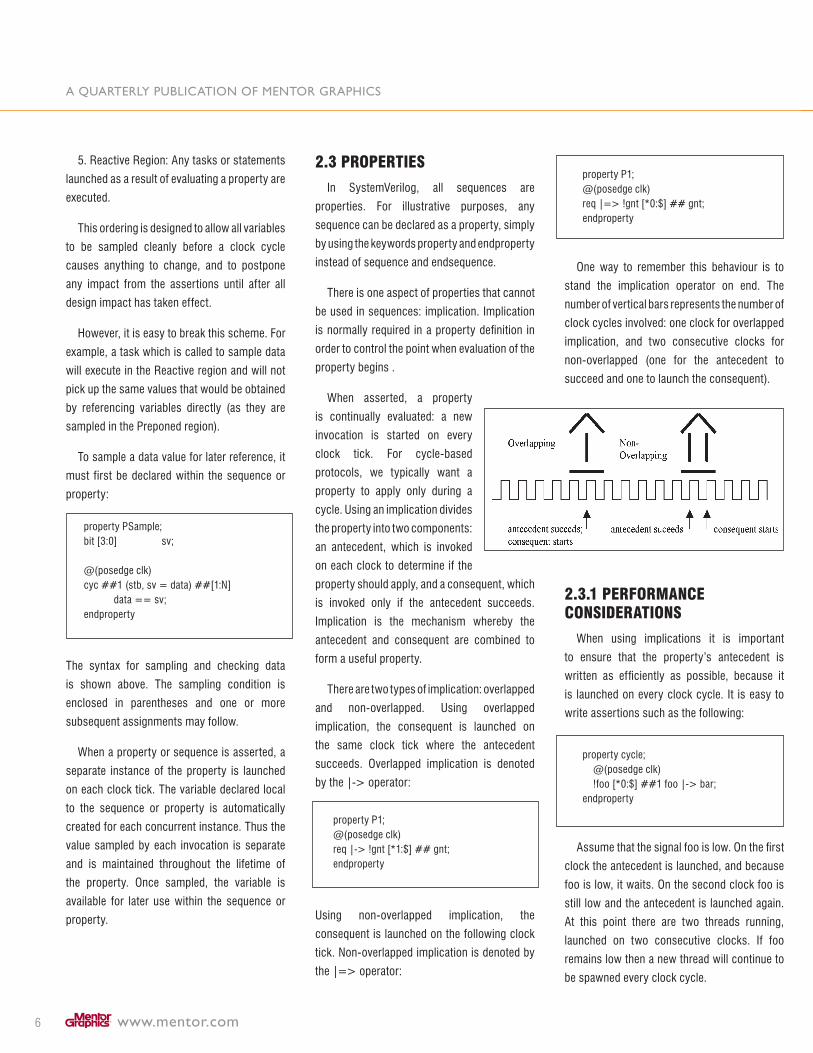
by the |-> operator: property P1;@(posedge clk)req |-> !gnt [*1:$] ## gnt;endproperty
Using non-overlapped implication, the
consequent is launched on the following clock
tick. Non-overlapped implication is denoted by
the |=> operator:
property P1;@(posedge clk)req |=> !gnt [*0:$] ## gnt;endproperty
One way to remember this behaviour is to
stand the implication operator on end. The
number of vertical bars represents the number of
clock cycles involved: one clock for overlapped
implication, and two consecutive clocks for
non-overlapped (one for the antecedent to
succeed and one to launch the consequent).
2.3.1 performAnce conSiDerAtionS
When using implications it is important
to ensure that the property’s antecedent is
written as efficiently as possible, because it
is launched on every clock cycle. It is easy to
write assertions such as the following:
property cycle; @(posedge clk) !foo [*0:$] ##1 foo |-> bar; endproperty
Assume that the signal foo is low. On the first
clock the antecedent is launched, and because
foo is low, it waits. On the second clock foo is
still low and the antecedent is launched again.
At this point there are two threads running,
launched on two consecutive clocks. If foo
remains low then a new thread will continue to
be spawned every clock cycle.

www.mentor.com 7
It is theoretically possible for simulators to
optimize sequences and properties so that new
threads are started only when needed. However,
it is impossible for a simulator to identify and
optimize all possible inefficient properties.
When confronted with the above scenario a
simulation will slow considerably. This behavior
is data-dependent however; once foo rises, all
threads will complete and performance will
return to normal.
The solution to this problem is to carefully
write assertions so that the antecedents don’t
persist unless they need to. Using the system
function $rose, the above example can be
rewritten as:
property cycle; @(posedge clk) $rose(foo) |-> bar;endproperty
This rule should be applied to consequents
as well. Once a property has done its job
and verified that a cycle is correct, it should
terminate immediately. It is just as easy to
write a lingering consequent as it is to write a
lingering antecedent.
Some SystemVerilog simulators support
code profiling, which can be helpful in finding
these problems. A simulator may also indicate
the lifetime of assertions in the waveform
viewer. Questa supports code profiling, and
will clearly show where assertions are taking
excessive time possibly due to the way they are
written.
2.3.2 implicAtion in DAtA cHecKS
When writing a property where data is
sampled by the antecedent and checked by the
consequent, be sure to use non-overlapping
implication. If overlapping implication is used
then the consequent will reference the data
before it is assigned. This problem is shown in
the following example:
// Verify that data doesn’t change between req and ack.property P;int x;
@(posedge clk)(req, x = data) |-> (ack, x == data);endproperty
This property, if asserted, would fail because
the consequent is comparing the value of the
data signal to the uninitialized variable x.
3 ASSertionS AnD VHDl DeSiGnS
Using the mixed language capabilities of
Questa, SystemVerilog assertions can be used
to verify VHDL designs. Assertions may involve
top level, module level, or internal design
signals.
3.1 uSinG tHe binD StAtement
If all VHDL signals of interest exist at the same
level of hierarchy, the bind statement is the
simplest way to connect them to SystemVerilog
assertions. Bind is a SystemVerilog statement
that can be executed from any module, interface,
or compilation unit scope. The bind statement
is also useful for Verilog-only designs because
it allows assertions to be encapsulated in a
separate module and easily reused.
The following example demonstrates the use of
the bind statement to connect SystemVerilog
assertions with a VHDL design. First, a
SystemVerilog module is created containing
the sequences, property definitions, and assert
statements required. The VHDL signals of
interest are named as inputs to this module.
module sv_assertions(input clk, a, b, c);
sequence a_before_b; @(posedge clk) a ##� (!a && b);endsequence
property c_rule; @(posedge clk) c |=> a_before_b;endproperty
assert property (c_rule) else $error (“Protocol violation.”);
endmodule
Next, a VHDL entity is instantiated inside a
separate SystemVerilog module. This could
be a top level module for a purely VHDL
design, or a lower level module in a mixed
language design.
module sv_mod1;
reg a_mod1, b_mod1, c_mod1;reg clk = 0;
top vhdl_top(.a(a_mod1), .b(b_mod1), .c(c_mod1), .clk(clk));
always clk = #5 ~clk;
endmodule
Finally, the assertions module is connected
to the VHDL block using the bind statement.
If the signals of interest are not present at
the top level of the VHDL, a hierarchical path
A quArterly publicAtion of mentor grAphics
www.mentor.com8
may be specified in the bind statement. The
VHDL signals named in the instantiation of the
assertion block can be either internal signals
or ports.
module sv_mod1;...bind vhdl_top.vhdl_block sv_assertions assert1(.a_mod1(a), .b_mod1(b), .c_mod1(c), .clk(clk));
endmodule
Using this procedure, multiple assertion
blocks may be connected to different locations
in the design hierarchy.
3.1 3.2 uSinG SiGnAlSpy
If assertions involve VHDL design signals
at more than one level of hierarchy, it is still
possible to connect all required signals using
the SignalSpy system tasks in addition to the
bind statement. SignalSpy allows the value of
any VHDL signal to be mirrored onto a Verilog
signal without affecting the source.
Building on the previous example, assume
that signal d is defined inside the architecture of
a VHDL block sub_block, which is instantiated
in vhdl_block. A corresponding internal signal,
also called d, is declared in the sv_assertions
module. A property and an assert statement are
written to verify the behaviour of d:
module sv_assertions(input clk, a, b, c);
reg d;
...
property d_rule; @(posedge clk) a |-> ##� d;
endproperty;
assert property (d_rule) else $error (“Behaviour of d incorrect.”);
endmodule
Using the $init_signal_spy system task, the
value of the VHDL signal d is mirrored onto the
Verilog register d:
module sv_mod1;
...
initial begin $init_signal_spy(“/sv_mod1/vhdl_top/ vhdl_block/sub_block/d”, “/sv_mod1/vhdl_top/vhdl_ block/assert1/d”);end
endmodule
The two required parameters for $init_signal_
spy are the source signal and the destination
signal. Each signal must be specified using its
complete hierarchical path. Once established,
the relationship between the two signals will
persist throughout the simulation. Optional
parameters are available to allow status
information to be printed to the simulation
transcript, and control whether the mirroring
can be disabled. For more information about
SignalSpy, please consult [1].
4 cASe StuDy: writinG ASSertionS for wiSHbone
In this section, the application of assertions
will be demonstrated using a practical example.
This case study will use the WISHBONE
SoC bus. First an overview of WISHBONE is
presented followed by a detailed description of
each assertion written to verify it.
This example uses a simple procedural
approach to writing assertions:
1. Analyze the protocol and derive a set of
rules governing its behaviour. Divide the rules
into two categories: temporal checks and data
checks.
�. Write a series of assertions to verify that
the signals involved are never unknown.
�. Write an assertion for each rule defined
in step 1.
4.1 wiSHbone oVerView
WISHBONE defines a point-to-point bus
for interconnecting cores on a chip. If more
than two devices are to be connected using
WISHBONE, then some type of bridge must
be used to connect them. This is left up to the
designer. The most basic implementation is an
arbiter and a mux; for more throughput a design
can use a crossbar switch.
Signals are named from the master’s
point of view. Everything (including reset) is
synchronous to a clock. Signals ending in “_o”
are driven by the master; signals ending in “_i”
are driven by the target.
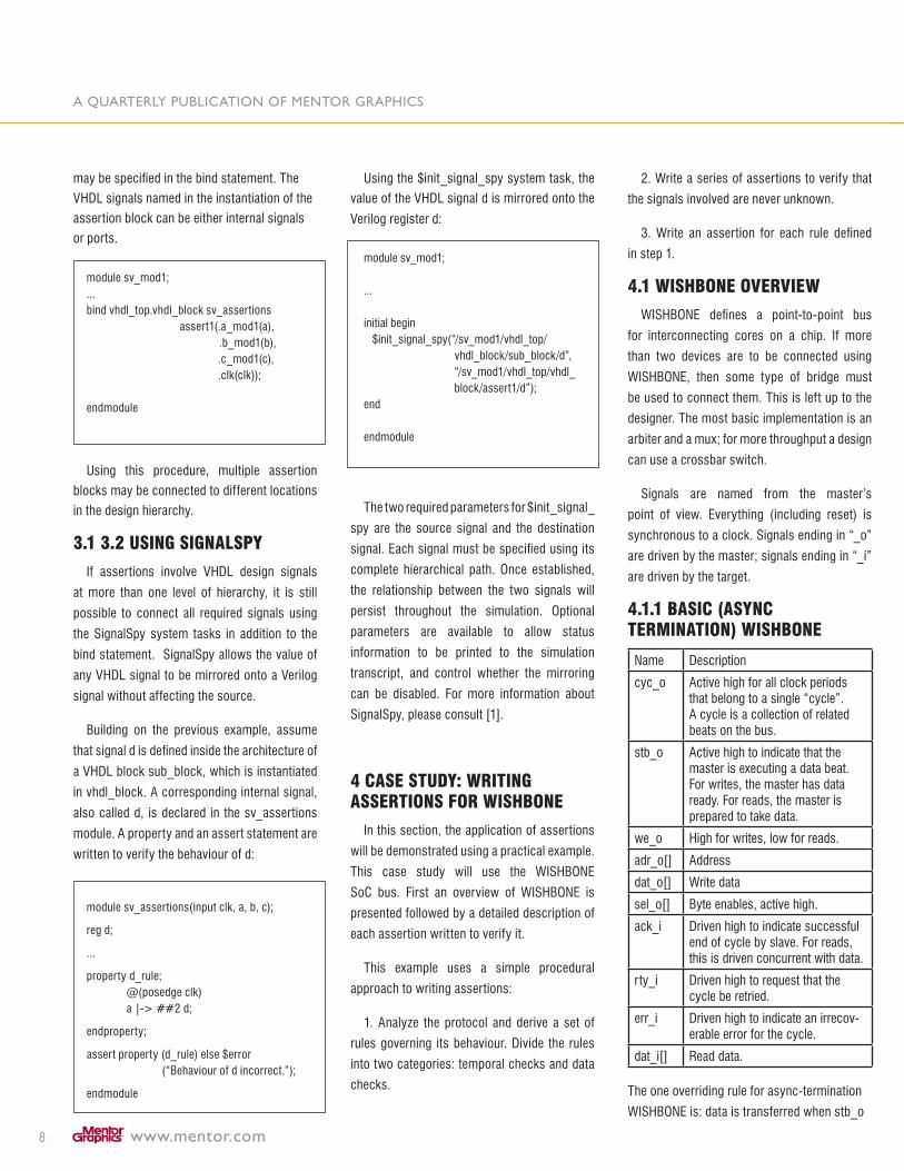
4.1.1 bASic (ASync terminAtion) wiSHbone
Name Description
cyc_o Active high for all clock periods that belong to a single “cycle”. A cycle is a collection of related beats on the bus.
stb_o Active high to indicate that the master is executing a data beat. For writes, the master has data ready. For reads, the master is prepared to take data.
we_o High for writes, low for reads.
adr_o[] Address
dat_o[] Write data
sel_o[] Byte enables, active high.
ack_i Driven high to indicate successful end of cycle by slave. For reads, this is driven concurrent with data.
rty_i Driven high to request that the cycle be retried.
err_i Driven high to indicate an irrecov-erable error for the cycle.
dat_i[] Read data.
The one overriding rule for async-termination
WISHBONE is: data is transferred when stb_o
www.mentor.com 9
and ack_i are both high. The master can insert
wait states by withholding stb_o; the slave can
insert wait states by withholding ack_i.
This protocol is almost asynchronous: if the
target is to respond on the same cycle as the
master so as to take one clock per beat, then
there is a purely combinational logic path from
stb_o to ack_i. A large setup time is usually
imposed on stb_o and other master signals.
If the target cannot meet timing then it must
register the master’s requests and reply a
clock later, which implies that each beat takes
two clock cycles.
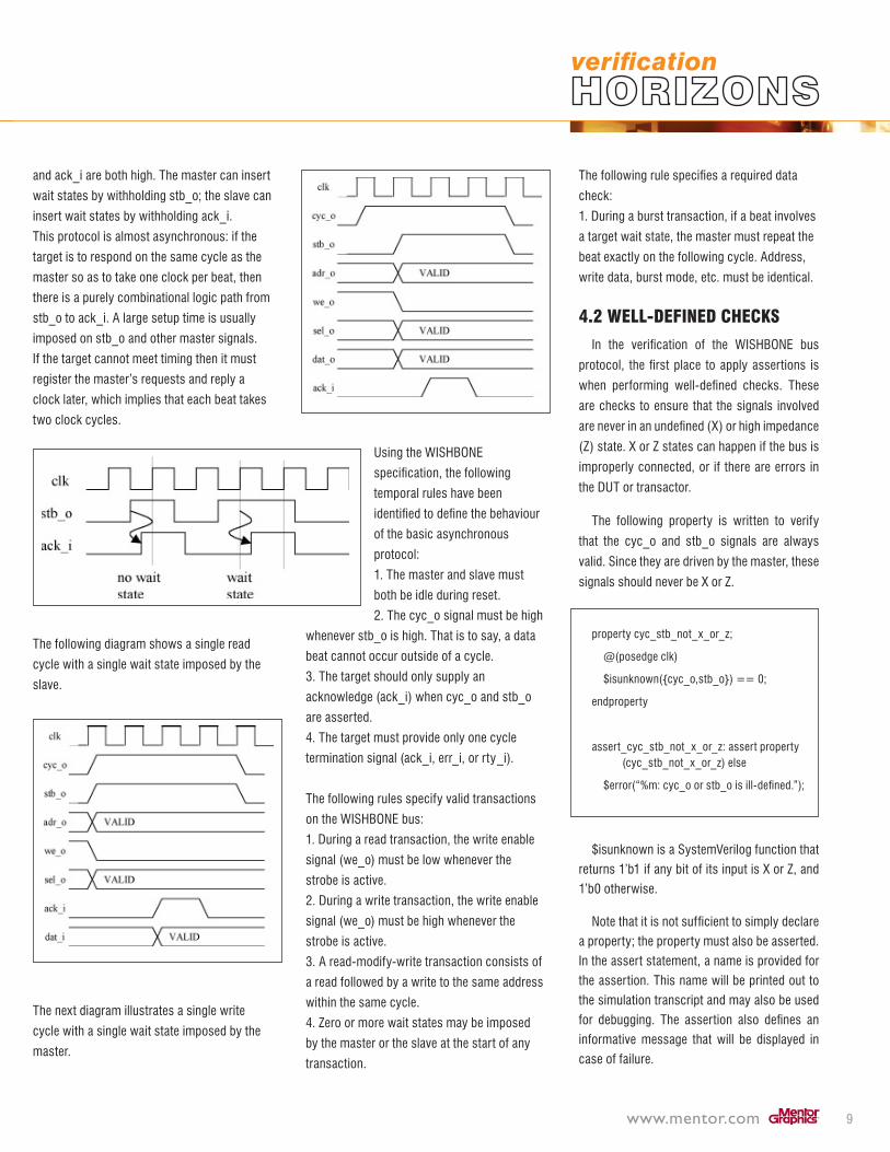
The following diagram shows a single read
cycle with a single wait state imposed by the
slave.
The next diagram illustrates a single write
cycle with a single wait state imposed by the
master.
Using the WISHBONE
specification, the following
temporal rules have been
identified to define the behaviour
of the basic asynchronous
protocol:
1. The master and slave must
both be idle during reset.
�. The cyc_o signal must be high
whenever stb_o is high. That is to say, a data
beat cannot occur outside of a cycle.
�. The target should only supply an
acknowledge (ack_i) when cyc_o and stb_o
are asserted.
4. The target must provide only one cycle
termination signal (ack_i, err_i, or rty_i).
The following rules specify valid transactions
on the WISHBONE bus:
1. During a read transaction, the write enable
signal (we_o) must be low whenever the
strobe is active.
�. During a write transaction, the write enable
signal (we_o) must be high whenever the
strobe is active.
�. A read-modify-write transaction consists of
a read followed by a write to the same address
within the same cycle.
4. Zero or more wait states may be imposed
by the master or the slave at the start of any
transaction.
The following rule specifies a required data
check:
1. During a burst transaction, if a beat involves
a target wait state, the master must repeat the
beat exactly on the following cycle. Address,
write data, burst mode, etc. must be identical.
4.2 well-DefineD cHecKS
In the verification of the WISHBONE bus
protocol, the first place to apply assertions is
when performing well-defined checks. These
are checks to ensure that the signals involved
are never in an undefined (X) or high impedance
(Z) state. X or Z states can happen if the bus is
improperly connected, or if there are errors in
the DUT or transactor.
The following property is written to verify
that the cyc_o and stb_o signals are always
valid. Since they are driven by the master, these
signals should never be X or Z.
property cyc_stb_not_x_or_z;
@(posedge clk)
$isunknown({cyc_o,stb_o}) == 0;
endproperty
assert_cyc_stb_not_x_or_z: assert property (cyc_stb_not_x_or_z) else
$error(“%m: cyc_o or stb_o is ill-defined.”);
$isunknown is a SystemVerilog function that
returns 1’b1 if any bit of its input is X or Z, and
1’b0 otherwise.
Note that it is not sufficient to simply declare
a property; the property must also be asserted.
In the assert statement, a name is provided for
the assertion. This name will be printed out to
the simulation transcript and may also be used
for debugging. The assertion also defines an
informative message that will be displayed in
case of failure.
A quArterly publicAtion of mentor grAphics
www.mentor.com10
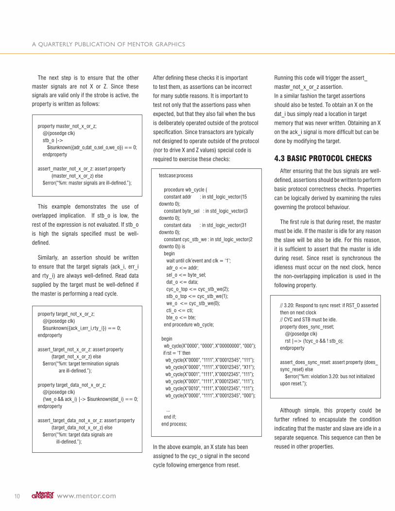
The next step is to ensure that the other
master signals are not X or Z. Since these
signals are valid only if the strobe is active, the
property is written as follows:
property master_not_x_or_z; @(posedge clk) stb_o |-> $isunknown({adr_o,dat_o,sel_o,we_o}) == 0; endproperty
assert_master_not_x_or_z: assert property (master_not_x_or_z) else $error(“%m: master signals are ill-defined.”);
This example demonstrates the use of
overlapped implication. If stb_o is low, the
rest of the expression is not evaluated. If stb_o
is high the signals specified must be well-
defined.
Similarly, an assertion should be written
to ensure that the target signals (ack_i, err_i
and rty_i) are always well-defined. Read data
supplied by the target must be well-defined if
the master is performing a read cycle.
property target_not_x_or_z; @(posedge clk) $isunknown({ack_i,err_i,rty_i}) == 0;endproperty
assert_target_not_x_or_z: assert property (target_not_x_or_z) else $error(“%m: target termination signals are ill-defined.”);
property target_data_not_x_or_z; @(posedge clk) (!we_o && ack_i) |-> $isunknown(dat_i) == 0;endproperty
assert_target_data_not_x_or_z: assert property (target_data_not_x_or_z) else $error(“%m: target data signals are ill-defined.”);
After defining these checks it is important
to test them, as assertions can be incorrect
for many subtle reasons. It is important to
test not only that the assertions pass when
expected, but that they also fail when the bus
is deliberately operated outside of the protocol
specification. Since transactors are typically
not designed to operate outside of the protocol
(nor to drive X and Z values) special code is
required to exercise these checks:
testcase:process
procedure wb_cycle ( constant addr : in std_logic_vector(15 downto 0); constant byte_sel : in std_logic_vector(� downto 0); constant data : in std_logic_vector(�1 downto 0); constant cyc_stb_we : in std_logic_vector(� downto 0)) is begin wait until clk’event and clk = ‘1’; adr_o <= addr; sel_o <= byte_sel; dat_o <= data; cyc_o_top <= cyc_stb_we(�); stb_o_top <= cyc_stb_we(1); we_o <= cyc_stb_we(0); cti_o <= cti; bte_o <= bte; end procedure wb_cycle; begin wb_cycle(X”0000”, “0000”, X”00000000”, “000”); if rst = ‘1’ then wb_cycle(X”0000”, “1111”, X”0001��45”, “111”); wb_cycle(X”0000”, “1111”, X”0001��45”, “X11”); wb_cycle(X”0001”, “1111”, X”0001��45”, “111”); wb_cycle(X”0001”, “1111”, X”0001��45”, “111”); wb_cycle(X”0010”, “1111”, X”0001��45”, “111”); wb_cycle(X”0000”, “1111”, X”0001��45”, “000”);
... end if; end process;
In the above example, an X state has been
assigned to the cyc_o signal in the second
cycle following emergence from reset.
Running this code will trigger the assert_
master_not_x_or_z assertion.
In a similar fashion the target assertions
should also be tested. To obtain an X on the
dat_i bus simply read a location in target
memory that was never written. Obtaining an X
on the ack_i signal is more difficult but can be
done by modifying the target.
4.3 bASic protocol cHecKS
After ensuring that the bus signals are well-
defined, assertions should be written to perform
basic protocol correctness checks. Properties
can be logically derived by examining the rules
governing the protocol behaviour.
The first rule is that during reset, the master
must be idle. If the master is idle for any reason
the slave will be also be idle. For this reason,
it is sufficient to assert that the master is idle
during reset. Since reset is synchronous the
idleness must occur on the next clock, hence
the non-overlapping implication is used in the
following property.
// �.�0: Respond to sync reset: if RST_O asserted then on next clock// CYC and STB must be idle.property does_sync_reset; @(posedge clk) rst |=> (!cyc_o && ! stb_o);endproperty
assert_does_sync_reset: assert property (does_sync_reset) else $error(“%m: violation �.�0: bus not initialized upon reset.”);
Although simple, this property could be
further refined to encapsulate the condition
indicating that the master and slave are idle in a
separate sequence. This sequence can then be
reused in other properties.
www.mentor.com 11
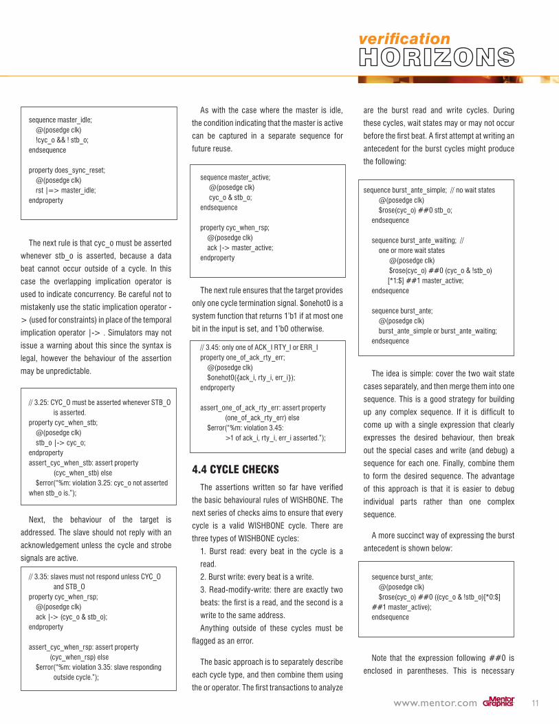
sequence master_idle; @(posedge clk) !cyc_o && ! stb_o;endsequence
property does_sync_reset; @(posedge clk) rst |=> master_idle;endproperty
The next rule is that cyc_o must be asserted
whenever stb_o is asserted, because a data
beat cannot occur outside of a cycle. In this
case the overlapping implication operator is
used to indicate concurrency. Be careful not to
mistakenly use the static implication operator -
> (used for constraints) in place of the temporal
implication operator |-> . Simulators may not
issue a warning about this since the syntax is
legal, however the behaviour of the assertion
may be unpredictable.
// �.�5: CYC_O must be asserted whenever STB_O is asserted.property cyc_when_stb; @(posedge clk) stb_o |-> cyc_o;endpropertyassert_cyc_when_stb: assert property (cyc_when_stb) else $error(“%m: violation �.�5: cyc_o not asserted when stb_o is.”);
Next, the behaviour of the target is
addressed. The slave should not reply with an
acknowledgement unless the cycle and strobe
signals are active.
// �.�5: slaves must not respond unless CYC_O and STB_Oproperty cyc_when_rsp; @(posedge clk) ack |-> (cyc_o & stb_o); endproperty
assert_cyc_when_rsp: assert property (cyc_when_rsp) else $error(“%m: violation �.�5: slave responding outside cycle.”);
As with the case where the master is idle,
the condition indicating that the master is active
can be captured in a separate sequence for
future reuse.
sequence master_active; @(posedge clk) cyc_o & stb_o; endsequence
property cyc_when_rsp; @(posedge clk) ack |-> master_active; endproperty
The next rule ensures that the target provides
only one cycle termination signal. $onehot0 is a
system function that returns 1’b1 if at most one
bit in the input is set, and 1’b0 otherwise.
// �.45: only one of ACK_I RTY_I or ERR_Iproperty one_of_ack_rty_err; @(posedge clk) $onehot0({ack_i, rty_i, err_i});endproperty
assert_one_of_ack_rty_err: assert property (one_of_ack_rty_err) else $error(“%m: violation �.45: >1 of ack_i, rty_i, err_i asserted.”);
4.4 cycle cHecKS
The assertions written so far have verified
the basic behavioural rules of WISHBONE. The
next series of checks aims to ensure that every
cycle is a valid WISHBONE cycle. There are
three types of WISHBONE cycles:
1. Burst read: every beat in the cycle is a
read.
�. Burst write: every beat is a write.
�. Read-modify-write: there are exactly two
beats: the first is a read, and the second is a
write to the same address.
Anything outside of these cycles must be
flagged as an error.
The basic approach is to separately describe
each cycle type, and then combine them using
the or operator. The first transactions to analyze
are the burst read and write cycles. During
these cycles, wait states may or may not occur
before the first beat. A first attempt at writing an
antecedent for the burst cycles might produce
the following:
sequence burst_ante_simple; // no wait states
@(posedge clk) $rose(cyc_o) ##0 stb_o;endsequence
sequence burst_ante_waiting; // one or more wait states @(posedge clk) $rose(cyc_o) ##0 (cyc_o & !stb_o) [*1:$] ##1 master_active;endsequence
sequence burst_ante; @(posedge clk) burst_ante_simple or burst_ante_waiting;endsequence
The idea is simple: cover the two wait state
cases separately, and then merge them into one
sequence. This is a good strategy for building
up any complex sequence. If it is difficult to
come up with a single expression that clearly
expresses the desired behaviour, then break
out the special cases and write (and debug) a
sequence for each one. Finally, combine them
to form the desired sequence. The advantage
of this approach is that it is easier to debug
individual parts rather than one complex
sequence.
A more succinct way of expressing the burst
antecedent is shown below:
sequence burst_ante; @(posedge clk) $rose(cyc_o) ##0 ((cyc_o & !stb_o)[*0:$] ##1 master_active);endsequence
Note that the expression following ##0 is
enclosed in parentheses. This is necessary

A quArterly publicAtion of mentor grAphics
www.mentor.com1�
because the repetition could repeat zero times,
and if the repetition expression were connected
to the ##0 the result would be an invalid
sequence that will never succeed. However,
if the repetition is combined with the ##1
following it, then the resulting expression does
consume time and can be connected to the
##0 without problems.
Which version of the burst antecedent
is better? From a performance standpoint
a simulator should optimize them to be
equivalent. From a clarity standpoint the first
version is superior and more appropriate for
novice assertion users.
Now that the antecedent has been created
the burst read and write cycles can be defined.
During a burst cycle, the strobe signal may
fluctuate due to wait states imposed by the
master. For a burst write operation, the write
enable signal should always be high whenever
the strobe is active. The opposite is true for a
burst read. A cycle ends when cyc_o falls.
sequence burst_end; @(posedge clk) !cyc_o [->1];endsequence
sequence burst_write_cons; @(posedge clk) (!stb_o | we_o) throughout burst_end;endsequence
property burst_write; @(posedge clk) burst_ante |-> burst_write_cons;endproperty
sequence burst_read_cons; @(posedge clk) (!stb_o | !we_o) throughout burst_end;endsequence
property burst_read; @(posedge clk) burst_ante |-> burst_read_cons;endproperty
The sequence describing the termination
condition must be carefully written. Since
the throughout operator starts evaluating
both operands at the same time, the right-
hand argument must be a function that stays
alive throughout the cycle, and then succeeds
only once. The definition of burst_end works
because goto repetition allows multiple clocks
to elapse before the sequence succeeds. Using
$fell(cyc_o) instead will not work because this
sequence will fail immediately at the beginning
of the cycle.
Next the read-modify-write cycle is described,
also using the burst antecedent:
@(posedge clk) !cyc_o [->1];endsequence
sequence burst_write_cons; @(posedge clk) (!stb_o | we_o) throughout burst_end;endsequence
property burst_write; @(posedge clk) burst_ante |-> burst_write_cons;endproperty
sequence burst_read_cons; @(posedge clk) (!stb_o | !we_o) throughout burst_end;endsequence
property burst_read; @(posedge clk) burst_ante |-> burst_read_cons;endproperty
After the start of a burst cycle, the RMW
protocol requires a data beat. Goto repetition
is used to wait for the data beat, as any number
of idle clocks may elapse before it begins. Once
a data beat is detected, it is verified as a read
transaction (we_o low) and the address is
sampled. Note that “##0” is used to make the
read processing concurrent with the arrival of
the data beat. The same steps are done for the
write beat, at which point the address is also
compared to ensure it is the same as the read
address. Finally, the assertion must confirm
that the master attempts nothing else during
the cycle. This is indicated by the strobe signal
dropping and staying low until the end of the
cycle.
Finally, the three properties (RMW, read
and write) are combined to recognize all valid
cycles, and the resulting property is asserted.
property valid_burst_cycle; @(posedge clk) burst_ante |-> (rmw_cycle_cons or burst_read_cons or burst_write_cons);endproperty
assert_valid_burst_cycle: assert property (valid_burst_cycle) else $error(“%m: burst cycle direction not consistent.”);
Note that all of the properties must use a
common antecedent, since the or operator
requires that both operands are consecutively
launched. Using a common antecedent is
generally a good practice when comparing
multiple sequences. Using common guards
(sequences used as the second operand
to WITHIN, THROUGHOUT, etc.) is also
recommended. This approach should simplify
the process of writing assertions and avoid any
synchronization problems.
4.5 DAtA cHecKS
Lastly, a data check needs to be performed
to verify that the master is consistent across a
multi-cycle access involving target wait states.
Recall:
If a beat involves a target wait state, then
the master must repeat the beat exactly on
the following cycle. Address, write data, burst
mode, etc. must be identical.
This check involves sampling a set of signals
and comparing these values over multiple clock
www.mentor.com 1�
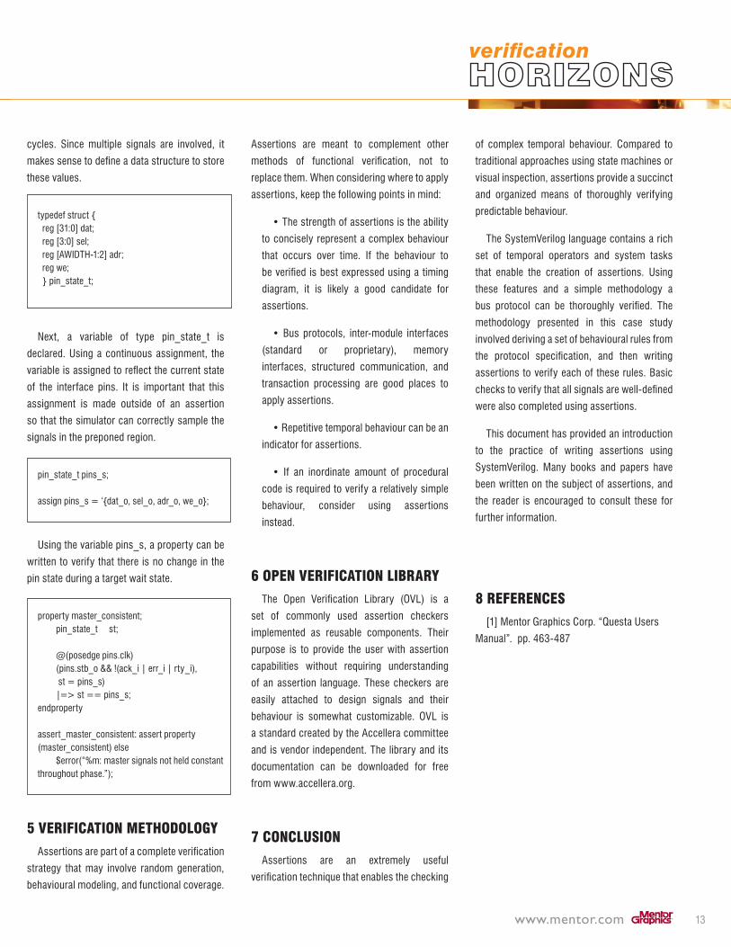
cycles. Since multiple signals are involved, it
makes sense to define a data structure to store
these values.
typedef struct { reg [�1:0] dat; reg [�:0] sel; reg [AWIDTH-1:�] adr; reg we; } pin_state_t;
Next, a variable of type pin_state_t is
declared. Using a continuous assignment, the
variable is assigned to reflect the current state
of the interface pins. It is important that this
assignment is made outside of an assertion
so that the simulator can correctly sample the
signals in the preponed region.
pin_state_t pins_s;
assign pins_s = ‘{dat_o, sel_o, adr_o, we_o};
Using the variable pins_s, a property can be
written to verify that there is no change in the
pin state during a target wait state.
property master_consistent; pin_state_t st;
@(posedge pins.clk) (pins.stb_o && !(ack_i | err_i | rty_i), st = pins_s) |=> st == pins_s;endproperty
assert_master_consistent: assert property (master_consistent) else $error(“%m: master signals not held constant throughout phase.”);
5 VerificAtion metHoDoloGy
Assertions are part of a complete verification
strategy that may involve random generation,
behavioural modeling, and functional coverage.
Assertions are meant to complement other
methods of functional verification, not to
replace them. When considering where to apply
assertions, keep the following points in mind:
• The strength of assertions is the ability
to concisely represent a complex behaviour
that occurs over time. If the behaviour to
be verified is best expressed using a timing
diagram, it is likely a good candidate for
assertions.
• Bus protocols, inter-module interfaces
(standard or proprietary), memory
interfaces, structured communication, and
transaction processing are good places to
apply assertions.
• Repetitive temporal behaviour can be an
indicator for assertions.
• If an inordinate amount of procedural
code is required to verify a relatively simple
behaviour, consider using assertions
instead.
6 open VerificAtion librAry
The Open Verification Library (OVL) is a
set of commonly used assertion checkers
implemented as reusable components. Their
purpose is to provide the user with assertion
capabilities without requiring understanding
of an assertion language. These checkers are
easily attached to design signals and their
behaviour is somewhat customizable. OVL is
a standard created by the Accellera committee
and is vendor independent. The library and its
documentation can be downloaded for free
from www.accellera.org.
7 concluSion
Assertions are an extremely useful
verification technique that enables the checking
of complex temporal behaviour. Compared to
traditional approaches using state machines or
visual inspection, assertions provide a succinct
and organized means of thoroughly verifying
predictable behaviour.
The SystemVerilog language contains a rich
set of temporal operators and system tasks
that enable the creation of assertions. Using
these features and a simple methodology a
bus protocol can be thoroughly verified. The
methodology presented in this case study
involved deriving a set of behavioural rules from
the protocol specification, and then writing
assertions to verify each of these rules. Basic
checks to verify that all signals are well-defined
were also completed using assertions.
This document has provided an introduction
to the practice of writing assertions using
SystemVerilog. Many books and papers have
been written on the subject of assertions, and
the reader is encouraged to consult these for
further information.
8 referenceS
[1] Mentor Graphics Corp. “Questa Users
Manual”. pp. 46�-487
A quArterly publicAtion of mentor grAphics
www.mentor.com14
I was recently on a long car trip driving my
MINI Cooper back from the Bay Area to my
home in Dallas, Texas, and with all that time
on my hands, I did plenty of thinking. As my
car traveled the highways, my mind did some
wandering around verification concepts. And
it struck me during the course of my journey
that executing a modern verification process
(involving constraints, assertions, and
coverage) is quite similar to executing a road trip
defined by a process of following a highlighted
map. Sounds like a far-fetched, travel-weary
idea? Well, maybe not. Let’s begin by looking
at coverage.
coVerAGe
If you think about it, during the course of
verification, today’s various coverage metrics
serve two primary purposes:
• Identify where we have been (that is, what
functionality or implementation structures have
been verified)
• Identify how far we have to go (that is, where
we currently stand in terms of completion)
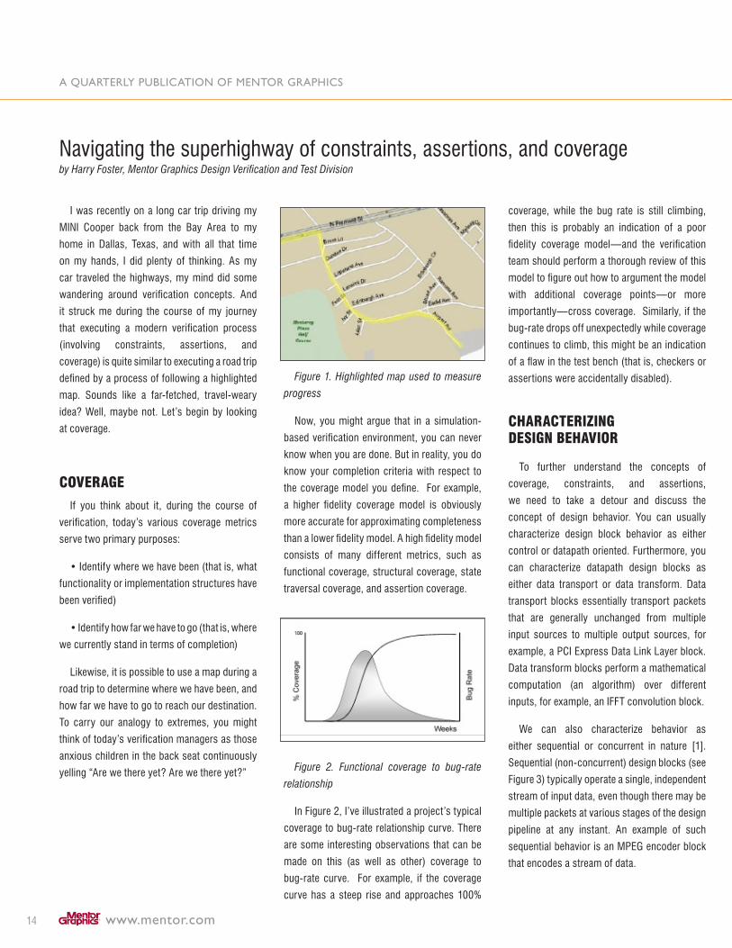
Likewise, it is possible to use a map during a
road trip to determine where we have been, and
how far we have to go to reach our destination.
To carry our analogy to extremes, you might
think of today’s verification managers as those
anxious children in the back seat continuously
yelling “Are we there yet? Are we there yet?”
Figure 1. Highlighted map used to measure
progress
Now, you might argue that in a simulation-
based verification environment, you can never
know when you are done. But in reality, you do
know your completion criteria with respect to
the coverage model you define. For example,
a higher fidelity coverage model is obviously
more accurate for approximating completeness
than a lower fidelity model. A high fidelity model
consists of many different metrics, such as
functional coverage, structural coverage, state
traversal coverage, and assertion coverage.
Figure 2. Functional coverage to bug-rate
relationship
In Figure �, I’ve illustrated a project’s typical
coverage to bug-rate relationship curve. There
are some interesting observations that can be
made on this (as well as other) coverage to
bug-rate curve. For example, if the coverage
curve has a steep rise and approaches 100%
coverage, while the bug rate is still climbing,
then this is probably an indication of a poor
fidelity coverage model—and the verification
team should perform a thorough review of this
model to figure out how to argument the model
with additional coverage points—or more
importantly—cross coverage. Similarly, if the
bug-rate drops off unexpectedly while coverage
continues to climb, this might be an indication
of a flaw in the test bench (that is, checkers or
assertions were accidentally disabled).
cHArActerizinG DeSiGn beHAVior
To further understand the concepts of
coverage, constraints, and assertions,
we need to take a detour and discuss the
concept of design behavior. You can usually
characterize design block behavior as either
control or datapath oriented. Furthermore, you
can characterize datapath design blocks as
either data transport or data transform. Data
transport blocks essentially transport packets
that are generally unchanged from multiple
input sources to multiple output sources, for
example, a PCI Express Data Link Layer block.
Data transform blocks perform a mathematical
computation (an algorithm) over different
inputs, for example, an IFFT convolution block.
We can also characterize behavior as
either sequential or concurrent in nature [1].
Sequential (non-concurrent) design blocks (see
Figure �) typically operate a single, independent
stream of input data, even though there may be
multiple packets at various stages of the design
pipeline at any instant. An example of such
sequential behavior is an MPEG encoder block
that encodes a stream of data.
Navigating the superhighway of constraints, assertions, and coverage
by Harry Foster, Mentor Graphics Design Verification and Test Division
www.mentor.com 15
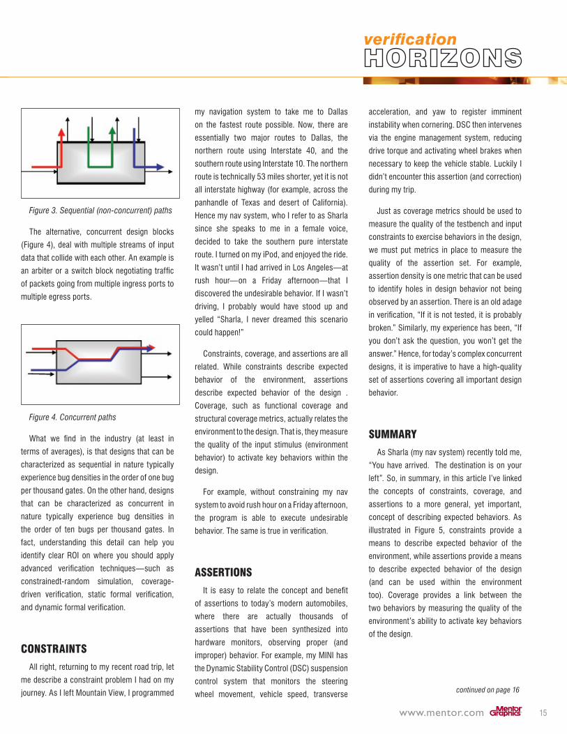
Figure 3. Sequential (non-concurrent) paths
The alternative, concurrent design blocks
(Figure 4), deal with multiple streams of input
data that collide with each other. An example is
an arbiter or a switch block negotiating traffic
of packets going from multiple ingress ports to
multiple egress ports.
Figure 4. Concurrent paths
What we find in the industry (at least in
terms of averages), is that designs that can be
characterized as sequential in nature typically
experience bug densities in the order of one bug
per thousand gates. On the other hand, designs
that can be characterized as concurrent in
nature typically experience bug densities in
the order of ten bugs per thousand gates. In
fact, understanding this detail can help you
identify clear ROI on where you should apply
advanced verification techniques—such as
constrainedt-random simulation, coverage-
driven verification, static formal verification,
and dynamic formal verification.
conStrAintS
All right, returning to my recent road trip, let
me describe a constraint problem I had on my
journey. As I left Mountain View, I programmed
my navigation system to take me to Dallas
on the fastest route possible. Now, there are
essentially two major routes to Dallas, the
northern route using Interstate 40, and the
southern route using Interstate 10. The northern
route is technically 5� miles shorter, yet it is not
all interstate highway (for example, across the
panhandle of Texas and desert of California).
Hence my nav system, who I refer to as Sharla
since she speaks to me in a female voice,
decided to take the southern pure interstate
route. I turned on my iPod, and enjoyed the ride.
It wasn’t until I had arrived in Los Angeles—at
rush hour—on a Friday afternoon—that I
discovered the undesirable behavior. If I wasn’t
driving, I probably would have stood up and
yelled “Sharla, I never dreamed this scenario
could happen!”
Constraints, coverage, and assertions are all
related. While constraints describe expected
behavior of the environment, assertions
describe expected behavior of the design .
Coverage, such as functional coverage and
structural coverage metrics, actually relates the
environment to the design. That is, they measure
the quality of the input stimulus (environment
behavior) to activate key behaviors within the
design.
For example, without constraining my nav
system to avoid rush hour on a Friday afternoon,
the program is able to execute undesirable
behavior. The same is true in verification.
ASSertionS
It is easy to relate the concept and benefit
of assertions to today’s modern automobiles,
where there are actually thousands of
assertions that have been synthesized into
hardware monitors, observing proper (and
improper) behavior. For example, my MINI has
the Dynamic Stability Control (DSC) suspension
control system that monitors the steering
wheel movement, vehicle speed, transverse
acceleration, and yaw to register imminent
instability when cornering. DSC then intervenes
via the engine management system, reducing
drive torque and activating wheel brakes when
necessary to keep the vehicle stable. Luckily I
didn’t encounter this assertion (and correction)
during my trip.
Just as coverage metrics should be used to
measure the quality of the testbench and input
constraints to exercise behaviors in the design,
we must put metrics in place to measure the
quality of the assertion set. For example,
assertion density is one metric that can be used
to identify holes in design behavior not being
observed by an assertion. There is an old adage
in verification, “If it is not tested, it is probably
broken.” Similarly, my experience has been, “If
you don’t ask the question, you won’t get the
answer.” Hence, for today’s complex concurrent
designs, it is imperative to have a high-quality
set of assertions covering all important design
behavior.
SummAry
As Sharla (my nav system) recently told me,
“You have arrived. The destination is on your
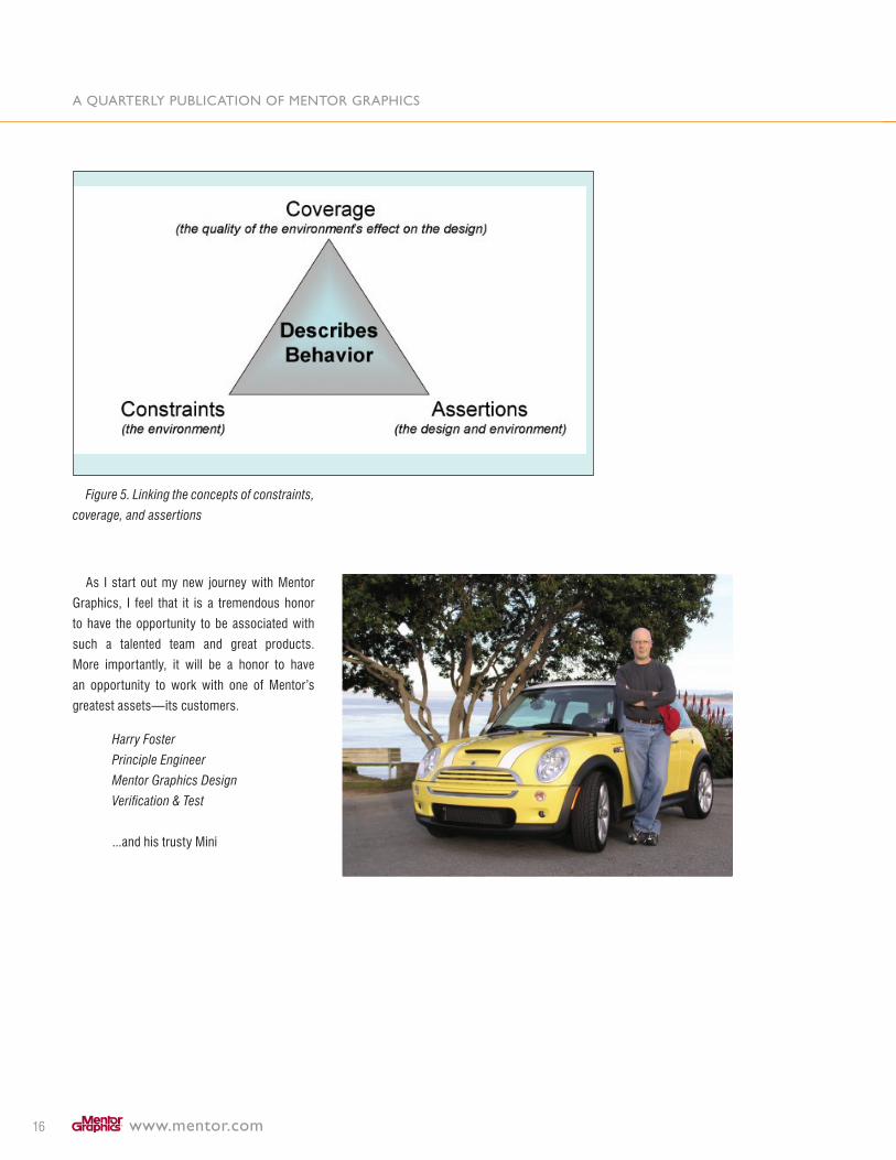
left”. So, in summary, in this article I’ve linked
the concepts of constraints, coverage, and
assertions to a more general, yet important,
concept of describing expected behaviors. As
illustrated in Figure 5, constraints provide a
means to describe expected behavior of the
environment, while assertions provide a means
to describe expected behavior of the design
(and can be used within the environment
too). Coverage provides a link between the
two behaviors by measuring the quality of the
environment’s ability to activate key behaviors
of the design.
continued on page 16
A quArterly publicAtion of mentor grAphics
www.mentor.com16
Figure 5. Linking the concepts of constraints,
coverage, and assertions
As I start out my new journey with Mentor
Graphics, I feel that it is a tremendous honor
to have the opportunity to be associated with
such a talented team and great products.
More importantly, it will be a honor to have
an opportunity to work with one of Mentor’s
greatest assets—its customers.
Harry Foster
Principle Engineer
Mentor Graphics Design
Verification & Test
...and his trusty Mini
www.mentor.com 17
The challenges of designing and verifying
hardware and embedded software for a
modern day system-on-chip (SoC) are well
documented in many of the articles and papers
of the electronics trade press, seminars and
trade shows. After all, the world has been
developing embedded systems since long
before the mobile phone industry started
making pocket-sized handsets. Today many of
these SoCs are based on one or more ARM®
processors, which offer excellent performance
while still being low power. Also, the ARM
processor range is exceptionally well supported
by Electronic Design Automation (EDA) tools
and flows which speed the implementation
and tape out of ARM Powered® products. In a
recent survey, EDA support ranked high in the
customer needs for embedded processors (see
the figure below for details).
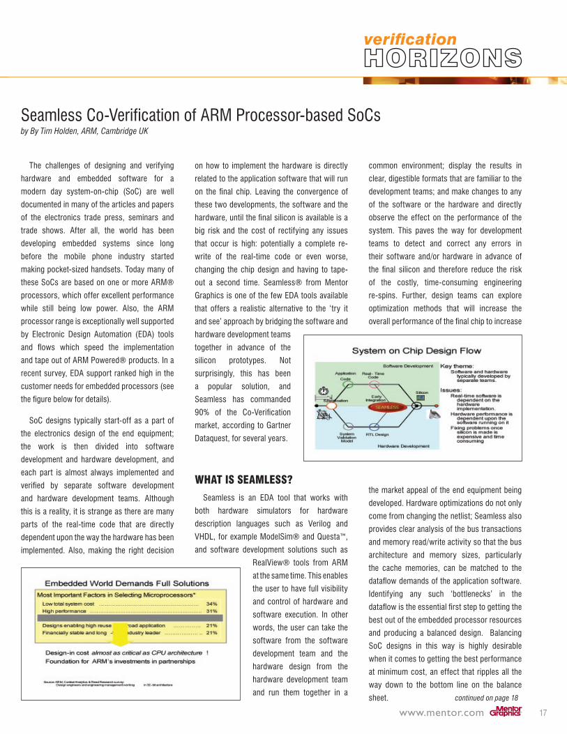
SoC designs typically start-off as a part of
the electronics design of the end equipment;
the work is then divided into software
development and hardware development, and
each part is almost always implemented and
verified by separate software development
and hardware development teams. Although
this is a reality, it is strange as there are many
parts of the real-time code that are directly
dependent upon the way the hardware has been
implemented. Also, making the right decision
on how to implement the hardware is directly
related to the application software that will run
on the final chip. Leaving the convergence of
these two developments, the software and the
hardware, until the final silicon is available is a
big risk and the cost of rectifying any issues
that occur is high: potentially a complete re-
write of the real-time code or even worse,
changing the chip design and having to tape-
out a second time. Seamless® from Mentor
Graphics is one of the few EDA tools available
that offers a realistic alternative to the ‘try it
and see’ approach by bridging the software and
hardware development teams
together in advance of the
silicon prototypes. Not
surprisingly, this has been
a popular solution, and
Seamless has commanded
90% of the Co-Verification
market, according to Gartner
Dataquest, for several years.
wHAt iS SeAmleSS?
Seamless is an EDA tool that works with
both hardware simulators for hardware
description languages such as Verilog and
VHDL, for example ModelSim® and Questa™,
and software development solutions such as
RealView® tools from ARM
at the same time. This enables
the user to have full visibility
and control of hardware and
software execution. In other
words, the user can take the
software from the software
development team and the
hardware design from the
hardware development team
and run them together in a
common environment; display the results in
clear, digestible formats that are familiar to the
development teams; and make changes to any
of the software or the hardware and directly
observe the effect on the performance of the
system. This paves the way for development
teams to detect and correct any errors in
their software and/or hardware in advance of
the final silicon and therefore reduce the risk
of the costly, time-consuming engineering
re-spins. Further, design teams can explore
optimization methods that will increase the
overall performance of the final chip to increase
the market appeal of the end equipment being
developed. Hardware optimizations do not only
come from changing the netlist; Seamless also
provides clear analysis of the bus transactions
and memory read/write activity so that the bus
architecture and memory sizes, particularly
the cache memories, can be matched to the
dataflow demands of the application software.
Identifying any such ‘bottlenecks’ in the
dataflow is the essential first step to getting the
best out of the embedded processor resources
and producing a balanced design. Balancing
SoC designs in this way is highly desirable
when it comes to getting the best performance
at minimum cost, an effect that ripples all the
way down to the bottom line on the balance
sheet. continued on page 18
Seamless Co-Verification of ARM Processor-based SoCs by By Tim Holden, ARM, Cambridge UK
A quArterly publicAtion of mentor grAphics
www.mentor.com18
SeAmleSS
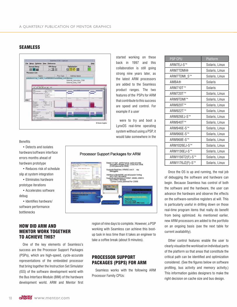
Benefits
• Detects and isolates
hardware/software interface
errors months ahead of
hardware prototype
• Reduces risk of schedule
slip at system integration
• Eliminates hardware
prototype iterations
• Accelerates software
debug
• Identifies hardware/
software performance
bottlenecks
How DiD Arm AnD mentor worK toGetHer to AcHieVe tHiS?
One of the key elements of Seamless’s
success are the Processor Support Packages
(PSPs), which are high-speed, cycle-accurate
representations of the embedded processor
that bring together the Instruction Set Simulator
(ISS) of the software development world with
the Bus Interface Module (BIM) of the hardware
development world. ARM and Mentor first
started working on these
back in 1997 and this
collaboration is still going
strong nine years later, as
the latest ARM processors
are added to the Seamless
product ranges. The two
features of the PSPs for ARM
that contribute to this success
are speed and control. For
example if a user
were to try and boot a
LynxOS real-time operating
system without using a PSP, it
would take somewhere in the
region of nine days to complete. However, a PSP
working with Seamless can achieve this boot-
up task in less time than it takes an engineer to
take a coffee break (about 9 minutes).
proceSSor Support pAcKAGeS (pSpS) for Arm
Seamless works with the following ARM
Processor Family CPUs:
PSP CPU Platform
ARM7EJ-S™ Solaris, Linux
ARM7TDMI® Solaris, Linux
ARM7TDMI_S™ Solaris, Linux
AMBA® Solaris
ARM710T™ Solaris
ARM7�0T™ Solaris, Linux
ARM9TDMI™ Solaris, Linux
ARM9�0T™ Solaris, Linux
ARM9��T™ Solaris, Linux
ARM9�6EJ-S™ Solaris, Linux
ARM940T™ Solaris, Linux
ARM946E-S™ Solaris, Linux
ARM966E-S™ Solaris, Linux
ARM968E-S™ Solaris, Linux
ARM10�6EJ-S™ Solaris, Linux
ARM11�6EJ-S™ Solaris, Linux
ARM1156T�(F)-S™ Solaris, Linux
ARM1176JZ(F)-S™ Solaris, Linux
Once the OS is up and running, the real job
of debugging the software and hardware can
begin. Because Seamless has control of both
the software and the hardware, the user can
advance the hardware and observe the effects
on the software-sensitive registers at will. This
is particularly useful in drilling down on those
real-time program items that really do benefit
from being optimized. As mentioned earlier,
new ARM processors are added to the portfolio
on an ongoing basis (see the next table for
current availability).
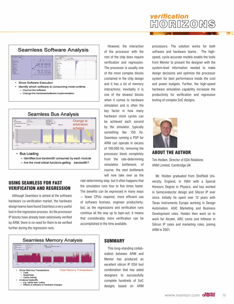
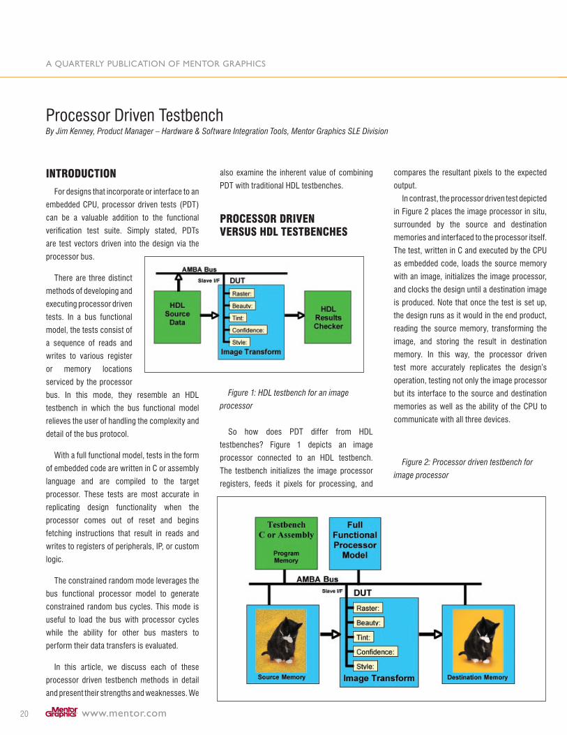
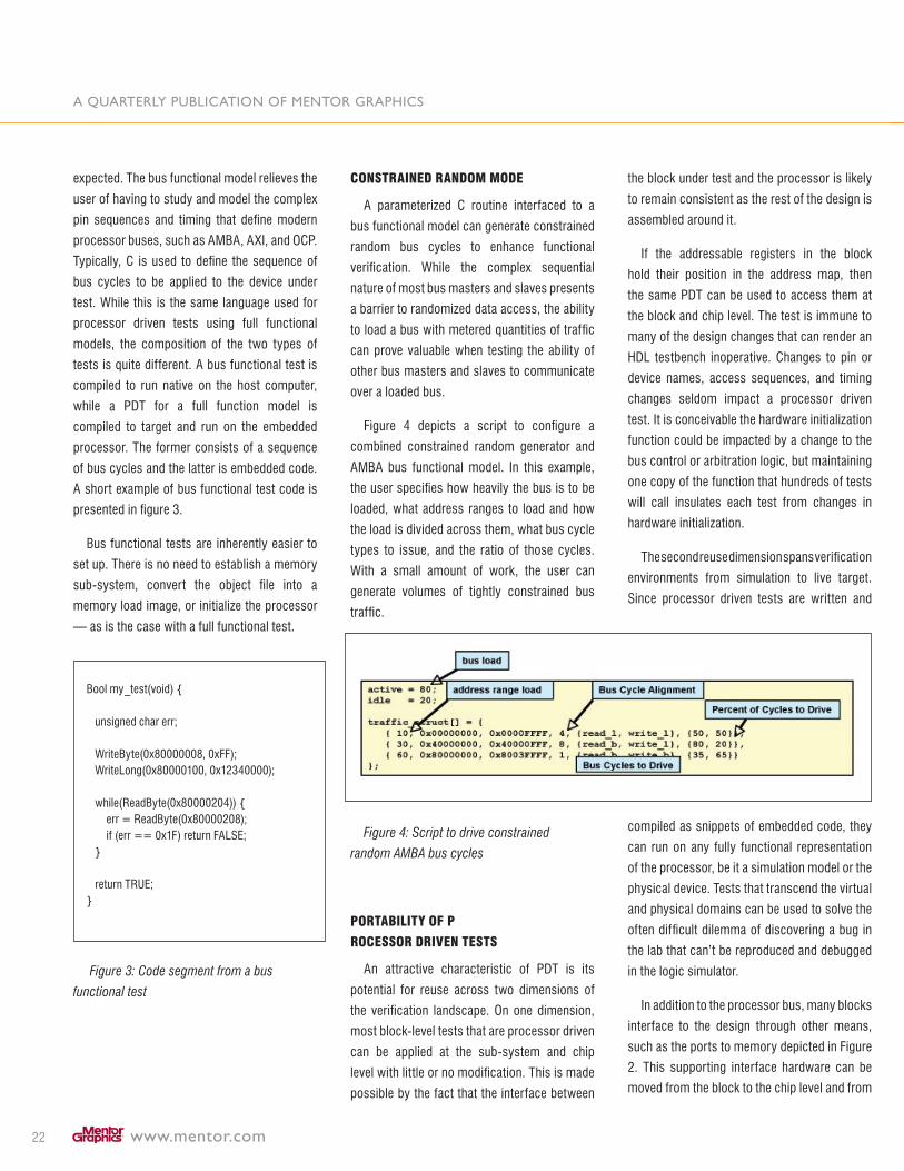
Other control features enable the user to
clearly visualize the workload on individual parts
of the platform so that areas that constitute the
critical path can be identified and optimization
considered. (See the figures below on software
profiling, bus activity and memory activity.)
This information guides designers to make the
right decision on cache size and bus design.
www.mentor.com 19
uSinG SeAmleSS for fASt VerificAtion AnD reGreSSion
Although Seamless is aimed at the software
hardware co-verification market, the hardware
design teams have found Seamless a very useful
tool in the regression process. As the processor
IP blocks have already been extensively verified
by ARM, there is no need for them to be verified
further during the regression runs.
However, the interaction
of the processor with the
rest of the chip does require
verification and regression.
The processor is usually one
of the most complex blocks
contained in the chip design
and it has a lot of memory
interactions; inevitably it is
one of the slowest blocks
when it comes to hardware
simulation and is often the
key factor in how many
hardware clock cycles can
be achieved each second
by the simulator, typically
something like 150 Hz.
Seamless running a PSP for
ARM can operate in excess
of 100,000 Hz, removing the
processor block completely
from the rate-determining
simulation bottleneck; of
course, the next bottleneck
will now take over as the
rate-determining step, but it often happens that
the simulation runs four to five times faster.
The benefits can be expressed in many ways
-- fewer CPUs required, more efficient use
of software licenses, engineer productivity;
but, as the regressions and verification runs
continue all the way up to tape-out, it means
that considerably more verification can be
accomplished in the time available.
SummAry
This long-standing collab-
oration between ARM and
Mentor has produced an
excellent silicon IP EDA tool
combination that has aided
designers to successfully
complete hundreds of SoC
designs based on ARM
processors. The solution works for both
software and hardware teams. The high-
speed, cycle-accurate models enable the tools
from Mentor to present the designer with the
system-level information needed to make
design decisions and optimize the processor
system for best performance inside the cost
and power budgets. Further, the high-speed
hardware simulation capability increases the
productivity for verification and regression
testing of complex SoC designs.
About tHe AutHor
Tim Holden, Director of EDA Relations
ARM Limited, Cambridge UK
Mr. Holden graduated from Sheffield Uni-
versity, England, in 1984 with a Special
Honours Degree in Physics, and has worked
in Semiconductor design and Silicon IP ever
since. Initially he spent over 1� years with
Texas Instruments Europe working in Design
Automation, ASIC Marketing and Business
Development roles. Holden then went on to
work for Alcatel, ARC cores and Infineon in
Silicon IP sales and marketing roles, joining
ARM in �001.
A quArterly publicAtion of mentor grAphics
www.mentor.com�0
introDuction
For designs that incorporate or interface to an
embedded CPU, processor driven tests (PDT)
can be a valuable addition to the functional
verification test suite. Simply stated, PDTs
are test vectors driven into the design via the
processor bus.
There are three distinct
methods of developing and
executing processor driven
tests. In a bus functional
model, the tests consist of
a sequence of reads and
writes to various register
or memory locations
serviced by the processor
bus. In this mode, they resemble an HDL
testbench in which the bus functional model
relieves the user of handling the complexity and
detail of the bus protocol.
With a full functional model, tests in the form
of embedded code are written in C or assembly
language and are compiled to the target
processor. These tests are most accurate in
replicating design functionality when the
processor comes out of reset and begins
fetching instructions that result in reads and
writes to registers of peripherals, IP, or custom
logic.
The constrained random mode leverages the
bus functional processor model to generate
constrained random bus cycles. This mode is
useful to load the bus with processor cycles
while the ability for other bus masters to
perform their data transfers is evaluated.
In this article, we discuss each of these
processor driven testbench methods in detail
and present their strengths and weaknesses. We
also examine the inherent value of combining
PDT with traditional HDL testbenches.
proceSSor DriVen VerSuS HDl teStbencHeS
Figure 1: HDL testbench for an image
processor
So how does PDT differ from HDL
testbenches? Figure 1 depicts an image
processor connected to an HDL testbench.
The testbench initializes the image processor
registers, feeds it pixels for processing, and
compares the resultant pixels to the expected
output.
In contrast, the processor driven test depicted
in Figure � places the image processor in situ,
surrounded by the source and destination
memories and interfaced to the processor itself.
The test, written in C and executed by the CPU
as embedded code, loads the source memory
with an image, initializes the image processor,
and clocks the design until a destination image
is produced. Note that once the test is set up,
the design runs as it would in the end product,
reading the source memory, transforming the
image, and storing the result in destination
memory. In this way, the processor driven
test more accurately replicates the design’s
operation, testing not only the image processor
but its interface to the source and destination
memories as well as the ability of the CPU to
communicate with all three devices.
Figure 2: Processor driven testbench for
image processor
Processor Driven Testbench By Jim Kenney, Product Manager – Hardware & Software Integration Tools, Mentor Graphics SLE Division

www.mentor.com �1
eASy pDt reuSe At tHe cHip leVel AnD on liVe tArGetS
It is not difficult to imagine this block-level
processor driven test being migrated to the
sub-system or chip level. Assuming additional
hardware interfaces are not inserted between
the image memories or image processor, the
C code for this test can be reused without
modification at the sub-system and chip level.
In fact, since the test is driven by the processor,
this test also can be run on the live target of an
FPGA prototype or the fabricated device itself.
Some care must be taken when constructing
the block level PDT test to ensure it can be reused
on the SoC or hardware prototype. In the case
of our image processor, some research into the
memory sub-system planned for the design will
allow consistent memory control initialization
and address ranges to be used at both the
block and chip level. If the detail on the memory
system design is not available when the block
test is being developed, the test will need to be
adapted to the final memory configuration in
order for the test to be migrated up to the sub-
system and chip levels. While these changes
are small, making small changes to hundreds
of tests is big job. Some forward thinking about
the end environment during the development
of the processor driven block tests will ease
downstream test reuse.
SyncHronizinG HDl teStbencHeS AnD pDtS
In the image processor example, the external
interfaces to the block under test were easily
implemented in hardware. Clearly there are
situations where this is not the case and an HDL
testbench must be used in conjunction with a
processor driven test to replicate the external
environment of the block. For this reason, it is
critical to be able to synchronize execution of
an HDL testbench with the code executing on
the full functional processor model.
Synchronization is easily accomplished
with existing hardware or software methods.
Logic simulator breakpoints can be used to
hold off the HDL testbench until the processor
has finished loading registers or memories.
Message passing is implemented by having the
processor poll a specified register or memory
location and waiting for the HDL testbench to
write the “proceed” value to that location. These
can be memory locations actually implemented
in the design or unused memory dedicated to
test synchronization.
moDeS of operAtion
Earlier we introduced the three distinct
methods of developing and executing processor
driven tests. Here we discuss each of them in
more detail.
full functionAl moDe
A full functional model replicates the
operation of the processor so it can be viewed
as a virtual, albeit slower, live target. The
same compiler and linker are used to generate
object code for the live target and the full
functional model. Because the full instruction-
set and operating modes are covered, the full
functional model can run any code destined
for the physical device. A typical exception is
JTAG and other dedicated debug hardware.
Since the model will run in the logic simulator,
which has its own debug environment, features
intended for debug of a live target are typically
excluded.
Typical operation for an embedded processor
is as follows: come out of reset, issue a memory
read to retrieve a reset vector, then branch to the
vectored memory location and begin executing
code. To support the processor’s native
operating mode, the user must load memory
with the reset vector and the object code to be
executed. Transforming the object file produced
by the compiler into a loadable memory image
is typically an exercise left to the user.
It is worth noting that although the goal of the
PDT is to verify operation of a custom design
block or IP, enough of the memory sub-system
must be modeled in the logic simulator to support
the processor’s requirement to fetch code from
memory and make data references to establish
local data store, software variables, and the
processor stack. While the interface between
the processor and memory must ultimately be
verified, modeling the memory sub-system is
tangential to performing a block test.
Full function processor models come in many
forms. Most are developed in C rather than
RTL, and all make some tradeoff with respect
to accuracy and performance. While faster is
usually better, it is important to consider the
speed of the complete environment. A complex
design described in RTL will simulate at a rate
measured in tens of clocks per second while
processor models can reach speeds of 100,000
to 1 million instructions per second. Given that
these two entities will be simulating in tandem, a
point of diminishing return on processor speed
is reached where a faster model simply spends
more time waiting for the logic simulator to
evaluate the RTL. A good trade-off is a cycle
accurate CPU model which accurately tracks
the function of the pipeline and runs at ~100K
instructions per second.
Usability is also a key factor when choosing
a processor model. For example, does it
support a source level debugger; how easy is it
to integrate; and what is the process for loading
object code.
buS functionAl moDe
In contrast to processor driven tests using
a full functional model, a bus functional model
supports more traditional testbenches. The user
specifies the desired bus cycle type, the address
to be accessed, and the data to be written or
A quArterly publicAtion of mentor grAphics
www.mentor.com��
expected. The bus functional model relieves the
user of having to study and model the complex
pin sequences and timing that define modern
processor buses, such as AMBA, AXI, and OCP.
Typically, C is used to define the sequence of
bus cycles to be applied to the device under
test. While this is the same language used for
processor driven tests using full functional
models, the composition of the two types of
tests is quite different. A bus functional test is
compiled to run native on the host computer,
while a PDT for a full function model is
compiled to target and run on the embedded
processor. The former consists of a sequence
of bus cycles and the latter is embedded code.
A short example of bus functional test code is
presented in figure �.
Bus functional tests are inherently easier to
set up. There is no need to establish a memory
sub-system, convert the object file into a
memory load image, or initialize the processor
— as is the case with a full functional test.
Bool my_test(void) { unsigned char err;
WriteByte(0x80000008, 0xFF); WriteLong(0x80000100, 0x1��40000);
while(ReadByte(0x80000�04)) { err = ReadByte(0x80000�08); if (err == 0x1F) return FALSE; }
return TRUE;}
Figure 3: Code segment from a bus
functional test
conStrAineD rAnDom moDe
A parameterized C routine interfaced to a
bus functional model can generate constrained
random bus cycles to enhance functional
verification. While the complex sequential
nature of most bus masters and slaves presents
a barrier to randomized data access, the ability
to load a bus with metered quantities of traffic
can prove valuable when testing the ability of
other bus masters and slaves to communicate
over a loaded bus.
Figure 4 depicts a script to configure a
combined constrained random generator and
AMBA bus functional model. In this example,
the user specifies how heavily the bus is to be
loaded, what address ranges to load and how
the load is divided across them, what bus cycle
types to issue, and the ratio of those cycles.
With a small amount of work, the user can
generate volumes of tightly constrained bus
traffic.
Figure 4: Script to drive constrained
random AMBA bus cycles
portAbility of p
roceSSor DriVen teStS
An attractive characteristic of PDT is its
potential for reuse across two dimensions of
the verification landscape. On one dimension,
most block-level tests that are processor driven
can be applied at the sub-system and chip
level with little or no modification. This is made
possible by the fact that the interface between
the block under test and the processor is likely
to remain consistent as the rest of the design is
assembled around it.
If the addressable registers in the block
hold their position in the address map, then
the same PDT can be used to access them at
the block and chip level. The test is immune to
many of the design changes that can render an
HDL testbench inoperative. Changes to pin or
device names, access sequences, and timing
changes seldom impact a processor driven
test. It is conceivable the hardware initialization
function could be impacted by a change to the
bus control or arbitration logic, but maintaining
one copy of the function that hundreds of tests
will call insulates each test from changes in
hardware initialization.
The second reuse dimension spans verification
environments from simulation to live target.
Since processor driven tests are written and
compiled as snippets of embedded code, they
can run on any fully functional representation
of the processor, be it a simulation model or the
physical device. Tests that transcend the virtual
and physical domains can be used to solve the
often difficult dilemma of discovering a bug in
the lab that can’t be reproduced and debugged
in the logic simulator.
In addition to the processor bus, many blocks
interface to the design through other means,
such as the ports to memory depicted in Figure
�. This supporting interface hardware can be
moved from the block to the chip level and from
www.mentor.com ��
simulation to a live target without modification.
In the case where an HDL testbench is used to
stimulate a non-processor bus interface, such
as a USB port, it is unlikely the HDL testbench
can be used with a live target. In this case,
the USB port must be physically interfaced to
hardware that may not behave identically to the
HDL testbench, so changes to the processor
driven test will need to occur to accommodate
connection to a physical device.
coDe SourceS for pDtS
blocK teStS
Typical processor driven test suites
include hundreds to thousands of small tests
designed to validate the many functional blocks
accessible through the CPU bus. Each must
start by calling a processor initialization routine
that sets up basic CPU functions like MMU,
cache, interrupts, and stack. Once initialization
is complete, the processor branches to “main”
and begins executing the test itself.
Although these tests are compiled to target
and execute on the full functional processor
model, most developers don’t consider
them firmware per se. They are simply block
tests written in C and applied to the intended
hardware by the CPU.
HArDwAre DiAGnoSticS
Nearly every embedded system design
project has a team of firmware engineers who
develop the hardware diagnostics. These are
used to bring up first silicon in the lab and in
manufacturing test. An abbreviated set is often
shipped with the product as a self test tool
for the end customer. Hardware diagnostics
make an excellent processor driven test for
simulation. Because they are developed from
the hardware specification, they represent on
orthogonal view of the design and often expose
discrepancies or ambiguities in the hardware
specification versus implementation.
Diagnostics are an excellent source of free
tests to the verification engineer. Considering
that hardware diagnostics are the first code
used to bring up first silicon or hardware
prototypes, it makes sense to run them during
simulation to expose and correct problems
prior to tape-out. Simulation provides an early
platform to develop and debug the diagnostics
to ensure that they are more robust when first
silicon arrives.
boot coDe
Another excellent source of free tests is the
boot-ROM code. Think of this as an elaborate
initialization routine that configures not only the
processor but much of the surrounding logic.
Boot code must complete successfully before
device drivers, real-time operating systems,
or application code can be executed. It is
often associated with “getting a prompt” on a
screen or display, and its successful execution
is considered a major milestone in bringing up
new hardware.
The same arguments for simulating hardware
diagnostics apply to boot code. The project
benefits from early checkout of this key piece of
code, and the hardware team adds a significant
verification routine to their suite of tests with
minimal effort: another free testbench.
This concept can be carried further with the
import of device drivers, real-time operating
systems, and application code. The highest
verification benefit is derived from firmware that
is highly interactive with the hardware. As you
move up the software complexity scale toward
application code, the hardware verification
value diminishes and the simulation runtime
increases dramatically.
queStA Support of proceSSor DriVen teStS
There are several limitations associated with
conducting processor driven tests in a classic
logic simulation environment. All center around
the introduction of embedded code into a tool
architected to model and simulate hardware.
DebuG ViSibility
The first and most obvious deficiency is lack
of visibility into the C code executing on the full
functional model. Hardware debug visibility is so
critical that an entire cottage industry has grown
to supply debug tools for Verilog simulators. Yet
the user is mostly blind to the C or assembly
code driving a processor driven test, so debug
must be done with logic viewing tools like a
waveform window. Simulators support source-
level debug of HDL or SystemC, but they don’t
make provisions for embedded code.
The full functional processor models offered
with the Questa™ advanced verification
environment have an integrated source-level
debugger that mimics most of the features
found in classic software debuggers, such as
GCC. Included is the ability to view and step
through source or assembly code, set break
points, and examine the contents of registers,
memories, and variables. These capabilities are
critical to isolating errors in either the design or
the test itself. Without source-level debug, the
full functional model appears for all practical
purposes as a stimulus generator of unknown
origin. The only clue to its behavior is a static
view of the C code driving the test.
performAnce
As discussed earlier, the primary limitation
to the effectiveness of processor driven tests
is the number and length of tests that can be
executed in the time allowed. It is the nature of
PDT that some data manipulation is performed
before bus cycles are issued to the hardware
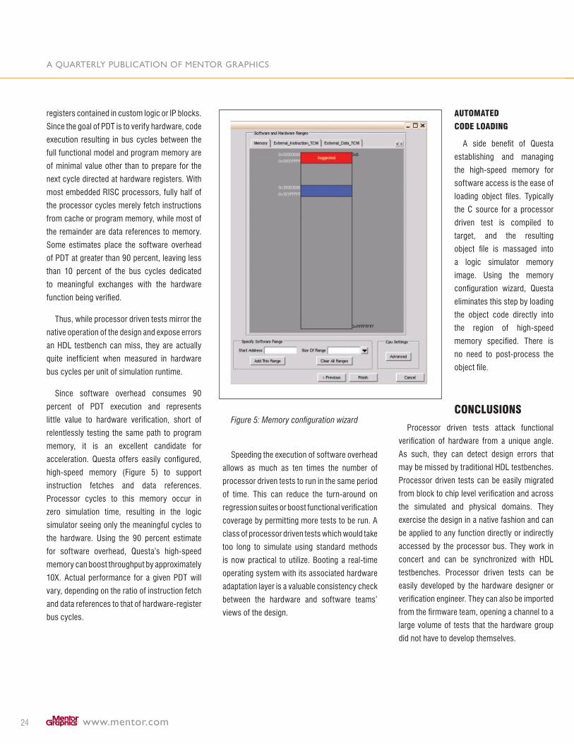
A quArterly publicAtion of mentor grAphics
www.mentor.com�4
registers contained in custom logic or IP blocks.
Since the goal of PDT is to verify hardware, code
execution resulting in bus cycles between the
full functional model and program memory are
of minimal value other than to prepare for the
next cycle directed at hardware registers. With
most embedded RISC processors, fully half of
the processor cycles merely fetch instructions
from cache or program memory, while most of
the remainder are data references to memory.
Some estimates place the software overhead
of PDT at greater than 90 percent, leaving less
than 10 percent of the bus cycles dedicated
to meaningful exchanges with the hardware
function being verified.
Thus, while processor driven tests mirror the
native operation of the design and expose errors
an HDL testbench can miss, they are actually
quite inefficient when measured in hardware
bus cycles per unit of simulation runtime.
Since software overhead consumes 90
percent of PDT execution and represents
little value to hardware verification, short of
relentlessly testing the same path to program
memory, it is an excellent candidate for
acceleration. Questa offers easily configured,
high-speed memory (Figure 5) to support
instruction fetches and data references.
Processor cycles to this memory occur in
zero simulation time, resulting in the logic
simulator seeing only the meaningful cycles to
the hardware. Using the 90 percent estimate
for software overhead, Questa’s high-speed
memory can boost throughput by approximately
10X. Actual performance for a given PDT will
vary, depending on the ratio of instruction fetch
and data references to that of hardware-register
bus cycles.
Figure 5: Memory configuration wizard
Speeding the execution of software overhead
allows as much as ten times the number of
processor driven tests to run in the same period
of time. This can reduce the turn-around on
regression suites or boost functional verification
coverage by permitting more tests to be run. A
class of processor driven tests which would take
too long to simulate using standard methods
is now practical to utilize. Booting a real-time
operating system with its associated hardware
adaptation layer is a valuable consistency check
between the hardware and software teams’
views of the design.
AutomAteD
coDe loADinG
A side benefit of Questa
establishing and managing
the high-speed memory for
software access is the ease of
loading object files. Typically
the C source for a processor
driven test is compiled to
target, and the resulting
object file is massaged into
a logic simulator memory
image. Using the memory
configuration wizard, Questa
eliminates this step by loading
the object code directly into
the region of high-speed
memory specified. There is
no need to post-process the
object file.
concluSionS
Processor driven tests attack functional
verification of hardware from a unique angle.
As such, they can detect design errors that
may be missed by traditional HDL testbenches.
Processor driven tests can be easily migrated
from block to chip level verification and across
the simulated and physical domains. They
exercise the design in a native fashion and can
be applied to any function directly or indirectly
accessed by the processor bus. They work in
concert and can be synchronized with HDL
testbenches. Processor driven tests can be
easily developed by the hardware designer or
verification engineer. They can also be imported
from the firmware team, opening a channel to a
large volume of tests that the hardware group
did not have to develop themselves.

www.mentor.com �5
Processor driven tests require a full functional
CPU model that also can be leveraged as a bus
functional model and bus traffic generator.
Questa offers several unique capabilities that
speed the execution of PDT and enrich the
debug experience. If your designs contain or are
interfaced to an embedded processor and you’re
not already taking advantage of processor driven
tests, you should consider adding them to your
hardware verification methodology.
About tHe AutHor
Jim Kenney has over �5 years of experience
in design validation and logic simulation and
has spent the bulk of his career at GenRad and
Mentor Graphics Corporation. At GenRad,
Jim worked on simulation-based test systems
incorporating the HiLo logic simulator and the
HiTest automatic test generator. At Mentor
Graphics, Jim has been responsible for analog/
mixed-signal simulation and hardware/software
co-verification. He is a Product Manager in the
System Level Engineering division and holds a
BSEE from Clemson University.
noteS

www.mentor.com �6
Editor: Tom Fitzpatrick
Program Manager: Rebecca Granquist
Wilsonville Worldwide Headquarters
8005 SW Boeckman Road
Wilsonville, OR 97070-7777
Phone: 50�-685-7000
Subscribe: http://www.mentor.com/products/
fv/verification_news.cfm