Embed Size (px)
Citation preview
International Journal of Emerging Trends & Technology in Computer Science (IJETTCS) Web Site: www.ijettcs.org Email: [email protected], [email protected]
Volume 3, Issue 4, July-August 2014 ISSN 2278-6856
Volume 3 Issue 4 July-August, 2014 Page 207
Abstract Touchless fingerprint sensing technologies have been developed to solve problems in touch-based sensing techniques because they do not require any contact between a sensor and a finger. While they can solve problems caused by the contact of a finger. In order to overcome these difficulties, we propose a new touchless fingerprint sensing device that captures image of fingerprint using camera. Human fingerprints are Unique. A critical step in automatic fingerprint matching is to reliably extract minutiae from the input fingerprint images. Here we first use several pre-processing steps on the binary image to enhance the quality of image, followed by minutia detection, removal of false minutia and features extraction. Final step is minutiae matching. The proposed method can be applied to other biometric applications requiring a large template for recognition. Keywords: Touchless fingerprint, minutia extraction, Gabor filter, Fingerprint recognition.
1. INTRODUCTION Fingerprint recognition systems have been widely adopted for user authentication due to their reliable performance and usability compared to other biometric systems. Recently, various kinds of fingerprint image acquisition sensors (including optical, solid-state, thermal, ultrasound, etc.) have been utilized in a wide range of forensic and commercial applications, e.g., criminal investigation, e-commerce, access control, issuing national ID cards and e-passports, etc. Because these types of sensing systems are touch-based, users must press or roll their fingers onto a platen surface to capture fingerprint images. Unfortunately, this capturing scheme often introduces degraded images due to skin deformation (due to skin elasticity and nonuniform pressure), skin condition changes (due to environmental changes and skin characteristics), and latent fingerprints on the sensor surface. Figs. 1(a) and (b) are two different images from the same finger. Due to skin deformation, the relative positions of minutiae sets from the two images are different. Figs. 1(c) and (d) show a minutiae type change due to the nonuniform pressure of the finger. As shown in Fig. 1(e), the ridge-valley contrast of an image can be severely affected by variations in skin condition, and Fig. 1(f) shows that a latent fingerprint remaining on the sensor surface can degrade the enhancement result of a newly captured image. Therefore, representation of the same fingerprint can vary at each acquisition, resulting in the inevitable degradation of the authentication performance [1]. Also, the rise in forgeries in touch-based sensor systems has
become a serious problem [14], [15]. While some individuals avoid public usage of Touch-based sensors due to concerns regarding hygiene [2].
Fig. 1 Distorted images acquired from a touch-based
sensor. To solve the above-mentioned problems, several advances in fingerprint sensing technology have been explored [3]. The multispectral fingerprint imaging (MSI) technique [4] was introduced to acquire better quality images from dry or wet fingers, and optical sensors with high resolution (over 1000 dpi) have been proposed to observe finer fingerprint features including sweat pores, incipient ridges, scars, and so on [5], [6]. However, these techniques are also touch-based, so they are not free from the problems caused by nonuniform, inconsistent, and irreproducible contacts. To overcome these kinds of problems, a touchless fingerprint sensing technology has been proposed that does not require any contact between a sensor and a finger. Thus, the finger’s minutiae and ridge information cannot be changed or distorted as it will be free of skin deformation. Also, it can capture fingerprint images consistently because it is not affected by different skin conditions or latent fingerprints. We adopt a new touch- less sensing scheme using a single camera. The device consists of a single camera, light-emitting diode (LED)-based illuminators. We consider minutiae and ridge points as the correspondences for initial alignment. It is explained in the rest of the paper.
2. FINGER PRINT A fingerprint is believed to be unique to each person (and each finger) [9]. Even the fingerprints of identical twins are different. The pattern is quite stable through our lifetime, in case of a cut; the same pattern will grow back. The features of a fingerprint depend on the nerve growth on the skins surface. This growth is determined by genetic factors and environmental factors such as nutrients,
An Approach to Touchless Fingerprint Recognition Using Matlab
Amrata A. Khindre1, V. A. More2 1Department of Electronics Engineering, Jawaharlal Nehru Engineering College,
N-6 Cidco, Aurangabad, Maharashtra, India. 2Department of Electronics Engineering, Jawaharlal Nehru Engineering College,
N-6 Cidco, Aurangabad, Maharashtra, India.

International Journal of Emerging Trends & Technology in Computer Science (IJETTCS) Web Site: www.ijettcs.org Email: [email protected], [email protected]
Volume 3, Issue 4, July-August 2014 ISSN 2278-6856
Volume 3 Issue 4 July-August, 2014 Page 208
oxygen levels and blood flow which are unique for every individual. Impression of fingerprints may be left behind on a surface by the natural secretions of sweat from the eccrine glands that are present in friction ridge skin, or they may be made by ink or other substances transferred from the peaks of friction ridges on the skin to a relatively smooth surface such as a fingerprint card. Fingerprints are one of the most full grown biometric technologies and are used as proofs of evidence in courts of law all over the world [10]. Fingerprints are, therefore, used in forensic divisions worldwide for criminal investigation. The performance of matching technique relies partly on the quality of the input fingerprints. In practice, due to skin conditions, sensor noise, incorrect finger pressure and bad quality workers, a significant percentage of fingerprint images are of poor quality. Hence we have used touchless fingerprint recognition approach.
2.1 FINGERPRINT IDENTIFICATION Fingerprint identification, known as dactyloscopy or hand print identification, is the process of comparing two instances of friction ridge skin impressions (see Minutiae), from human fingers, the palm of the hand or even toes, to determine whether these impressions could have come from the same individual [9]. The flexibility of friction ridge skin means that no two finger or palm prints are ever exactly alike in every detail; even two impressions recorded immediately after each other from the same hand. Fingerprint identification, also referred to as individualization, involves an expert, or an expert computer system operating under threshold scoring rules, determining whether two friction ridge impressions are likely to have originated from the same finger or palm.
2.2 FINGERPRINT MINUTIA The major Minutia features of fingerprint ridges are: ridge ending (termination), bifurcation, and short ridge (or dot) as shown in Fig. 2 and Fig. 3. The ridge ending is the point at which a ridge terminates. Bifurcations are points at which a single ridge splits into two ridges. Short ridges (or dot) are ridges which are significantly shorter than the average ridge length on the fingerprint. Minutia and patterns are very important in the analysis of fingerprints. Some typical examples of these fingerprint minutiae are shown in Fig. 4.
Fig. 2 Minutiae Points. (a) ridge ending (b) bifurcation
Fig3. Exact shape of different minutiae [10]
Fig. 4 some of the common minutiae types
2.3 FINGERPRINT RECOGNITION The fingerprint recognition problem can be grouped into three sub-domains: fingerprint enrollment, verification and fingerprint identification. In addition, different from the manual approach for fingerprint recognition by experts, the fingerprint recognition here is referred as AFRS (Automatic Fingerprint Recognition System), which is program-based. Verification is typically used for positive recognition, where the aim is to prevent multiple people from using the same identity. Fingerprint verification is to verify the authenticity of one person by his fingerprint. There is one-to-one comparison in this case. In the identification mode, the system recognizes an individual by searching the templates of all the users in the database for a match. Therefore, the system conducts a one-to-many comparison to establish an individual’s identity [10]. Practically, there is still no record that same fingerprint for different individuals has been found. Fingerprint imaging technology can now collect and read the complex pattern of human being’s finger. There are loop, whorl and arch patterns which are common patterns of a fingerprint. The data template captured is stored in database to be used as comparison when users scan their fingers. In biometric field, fingerprint verification system requires one of the largest data storage systems. The size of data template is around hundred to thousand bytes based on the security level and approach used to collect fingerprints. Fingerprint recognition system generally uses matching and comparing two sets of minutiae. By looking at the transformation of translation, rotation and correspondences between fingerprints captured and fingerprint from database. The matching will become non rigid after minutiae being extracted from image scanned. Besides, the skin elasticity may change relative to the position of minutiae.
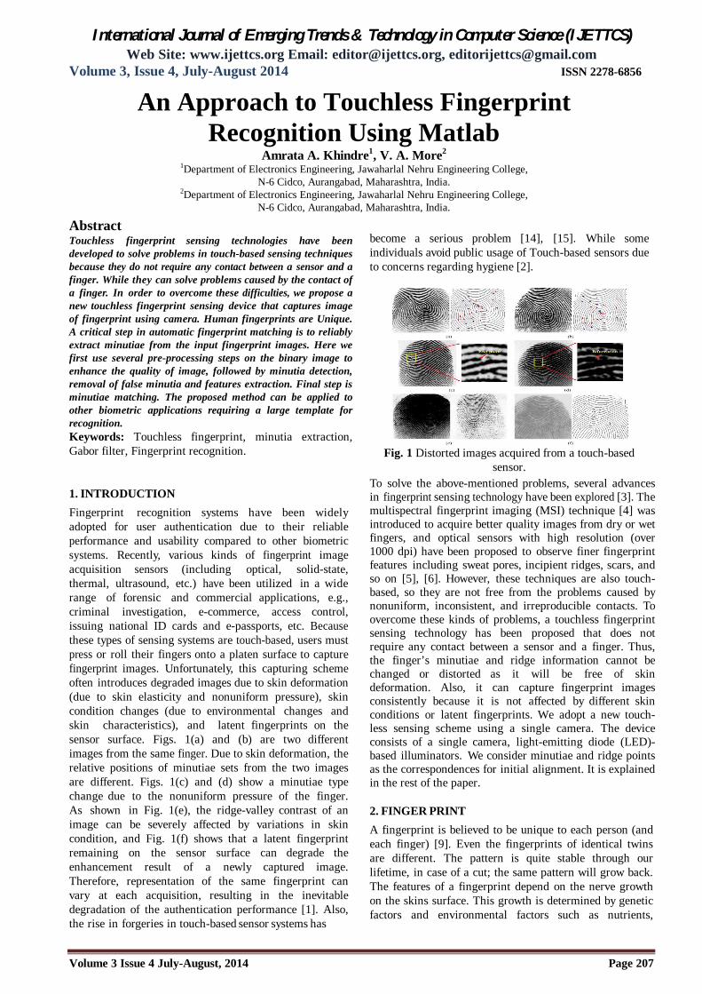
3. SYSTEM DESIGN To overcome the problems in touch based fingerprinting systems we adopt a new sensing system which captures fingerprint image by using a camera. Fig.5 shows the schematic view of the device. The frontal view of
International Journal of Emerging Trends & Technology in Computer Science (IJETTCS) Web Site: www.ijettcs.org Email: [email protected], [email protected]
Volume 3, Issue 4, July-August 2014 ISSN 2278-6856
Volume 3 Issue 4 July-August, 2014 Page 209
fingerpr in t i s captured by a single camera. In addition, to obtain high-quality fingerprint images, we need to consider several optical components in order to design the device. The specifications of the optical components are as follows:
Fig 5. Schematic view of the device 3.1 CAMERA We use a CCD sensor camera with image resolution of 1024x1280. This camera offers a sufficient frame rate of 30fps, thus avoiding image blurring caused by typical finger motion. Normally, the required image resolution for touch-based sensors is 500 dpi. Therefore, to ensure a 500-dpi spatial resolution in the fingerprint area and to cover fingerprint, distance should be 1-2cm. By doing this, we can capture images with 500-dpi resolution at one time. It normally covers the half depth of a finger. 3.2 ILLUMINATION Considering the reflectance of human skin to various light sources, we used ring-shaped white LED illuminators and a band pass filter which can transmit green light to enhance the ridge-to-valley contrast. Also, the illuminators are placed perpendicular to the finger to remove the shadowing effect [1]. Diffusers are used to illuminate a finger uniformly. 4. PROPOSED METHOD In this section, we explain the method for synthesizing a fingerprint image. The overall scheme of the method is presented in Fig. 6. The method is mainly composed of four stages (preprocessing, minutia extraction, post processing and final minutia matching). In preprocessing, we enhance the features of image. In minutia extraction, we extract minutiae and ridge information of each fingerprint and detect correspondences using minutiae and ridge points. After that, in post processing, we remove false minutia. Finally, we save and match the template. In the rest of this section, we explain the proposed method in detail.
Fig. 6 Minutia Extraction
4.1 FINGERPRINT IMAGE PREPROCESSING Following are the steps involved in pre-processing 4.1.1 Fingerprint Image Reading In this step, the fingerprint image is loaded by using the Matlab built-in function imread.
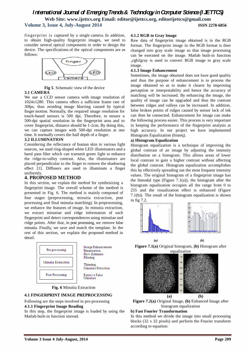
4.1.2 RGB to Gray Image Raw data of fingerprint image obtained is in the RGB format. The fingerprint image in the RGB format is then changed into gray scale image so that image processing can be executed on the image. Matlab built-in function „rgb2gray is used to convert RGB image to gray scale image. 4.1.3 Image Enhancement Sometimes, the image obtained does not have good quality and thus the purpose of enhancement is to process the image obtained so as to make it clearer by improving perception or interpretability and hence the accuracy of matching will be increased. By enhancing the image, the quality of image can be upgraded and thus the contrast between ridges and valleys can be increased. In addition, false broken points of ridges caused by sensor lack of ink can then be connected. Enhancement for image can make the following process easier. This process is very important in keeping the performance of the fingerprint analysis at high accuracy. In our project we have implemented Histogram Equalization (histeq). a) Histogram Equalization Histogram equalization is a technique of improving the global contrast of an image by adjusting the intensity distribution on a histogram. This allows areas of lower local contrast to gain a higher contrast without affecting the global contrast. Histogram equalization accomplishes this by effectively spreading out the most frequent intensity values. The original histogram of a fingerprint image has the bimodal type (Figure 7.1(a)), the histogram after the histogram equalization occupies all the range from 0 to 255 and the visualization effect is enhanced (Figure 7.1(b)). The result of the histogram equalization is shown in fig 7.2.
(a) (b)
Figure 7.1(a) Original histogram, (b) Histogram after equalization
(a) (b)
Figure 7.2(a) Original Image, (b) Enhanced Image after histogram equalization
b) Fast Fourier Transformation In this method we divide the image into small processing blocks (32 x 32 pixels) and perform the Fourier transform according to equation:
International Journal of Emerging Trends & Technology in Computer Science (IJETTCS) Web Site: www.ijettcs.org Email: [email protected], [email protected]
Volume 3, Issue 4, July-August 2014 ISSN 2278-6856
Volume 3 Issue 4 July-August, 2014 Page 210
(1) For u = 0, 1, 2, ..., 31 and v = 0, 1, 2, ..., 31. In order to enhance a specific block by its dominant frequencies, we multiply the FFT of the block by its magnitude a set of times. Where the magnitude of the original FFT = abs (F (u, v)) = |F (u, v)|. So we get the enhanced block according to the equation:
(2) Where (F (u, v)) is given by
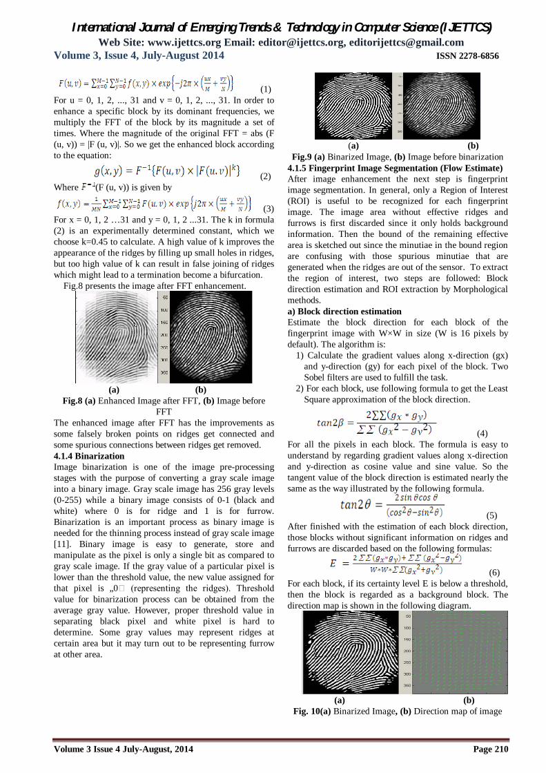
(3) For x = 0, 1, 2 …31 and y = 0, 1, 2 ...31. The k in formula (2) is an experimentally determined constant, which we choose k=0.45 to calculate. A high value of k improves the appearance of the ridges by filling up small holes in ridges, but too high value of k can result in false joining of ridges which might lead to a termination become a bifurcation. Fig.8 presents the image after FFT enhancement.
(a) (b)
Fig.8 (a) Enhanced Image after FFT, (b) Image before FFT
The enhanced image after FFT has the improvements as some falsely broken points on ridges get connected and some spurious connections between ridges get removed. 4.1.4 Binarization Image binarization is one of the image pre-processing stages with the purpose of converting a gray scale image into a binary image. Gray scale image has 256 gray levels (0-255) while a binary image consists of 0-1 (black and white) where 0 is for ridge and 1 is for furrow. Binarization is an important process as binary image is needed for the thinning process instead of gray scale image [11]. Binary image is easy to generate, store and manipulate as the pixel is only a single bit as compared to gray scale image. If the gray value of a particular pixel is lower than the threshold value, the new value assigned for that pixel is „0 (representing the ridges). Threshold value for binarization process can be obtained from the average gray value. However, proper threshold value in separating black pixel and white pixel is hard to determine. Some gray values may represent ridges at certain area but it may turn out to be representing furrow at other area.
(a) (b) Fig.9 (a) Binarized Image, (b) Image before binarization
4.1.5 Fingerprint Image Segmentation (Flow Estimate) After image enhancement the next step is fingerprint image segmentation. In general, only a Region of Interest (ROI) is useful to be recognized for each fingerprint image. The image area without effective ridges and furrows is first discarded since it only holds background information. Then the bound of the remaining effective area is sketched out since the minutiae in the bound region are confusing with those spurious minutiae that are generated when the ridges are out of the sensor. To extract the region of interest, two steps are followed: Block direction estimation and ROI extraction by Morphological methods. a) Block direction estimation Estimate the block direction for each block of the fingerprint image with W×W in size (W is 16 pixels by default). The algorithm is:
1) Calculate the gradient values along x-direction (gx) and y-direction (gy) for each pixel of the block. Two Sobel filters are used to fulfill the task.
2) For each block, use following formula to get the Least Square approximation of the block direction.
(4) For all the pixels in each block. The formula is easy to understand by regarding gradient values along x-direction and y-direction as cosine value and sine value. So the tangent value of the block direction is estimated nearly the same as the way illustrated by the following formula.
(5) After finished with the estimation of each block direction, those blocks without significant information on ridges and furrows are discarded based on the following formulas:
(6) For each block, if its certainty level E is below a threshold, then the block is regarded as a background block. The direction map is shown in the following diagram.
(a) (b)
Fig. 10(a) Binarized Image, (b) Direction map of image
International Journal of Emerging Trends & Technology in Computer Science (IJETTCS) Web Site: www.ijettcs.org Email: [email protected], [email protected]
Volume 3, Issue 4, July-August 2014 ISSN 2278-6856
Volume 3 Issue 4 July-August, 2014 Page 211
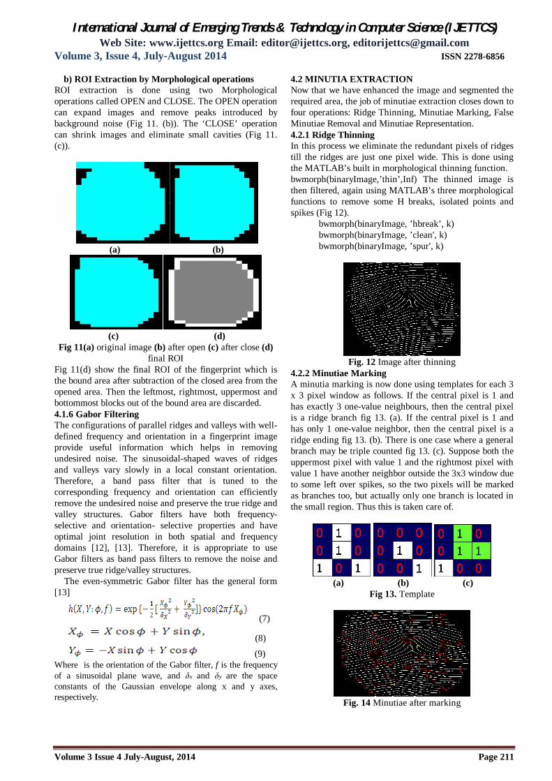
b) ROI Extraction by Morphological operations ROI extraction is done using two Morphological operations called OPEN and CLOSE. The OPEN operation can expand images and remove peaks introduced by background noise (Fig 11. (b)). The ‘CLOSE’ operation can shrink images and eliminate small cavities (Fig 11. (c)).
(a) (b)
(c) (d) Fig 11(a) original image (b) after open (c) after close (d)
final ROI Fig 11(d) show the final ROI of the fingerprint which is the bound area after subtraction of the closed area from the opened area. Then the leftmost, rightmost, uppermost and bottommost blocks out of the bound area are discarded. 4.1.6 Gabor Filtering The configurations of parallel ridges and valleys with well-defined frequency and orientation in a fingerprint image provide useful information which helps in removing undesired noise. The sinusoidal-shaped waves of ridges and valleys vary slowly in a local constant orientation. Therefore, a band pass filter that is tuned to the corresponding frequency and orientation can efficiently remove the undesired noise and preserve the true ridge and valley structures. Gabor filters have both frequency-selective and orientation- selective properties and have optimal joint resolution in both spatial and frequency domains [12], [13]. Therefore, it is appropriate to use Gabor filters as band pass filters to remove the noise and preserve true ridge/valley structures. The even-symmetric Gabor filter has the general form [13]
(7)
(8)
(9) Where is the orientation of the Gabor filter, f is the frequency of a sinusoidal plane wave, and δx and δy are the space constants of the Gaussian envelope along x and y axes, respectively.
4.2 MINUTIA EXTRACTION Now that we have enhanced the image and segmented the required area, the job of minutiae extraction closes down to four operations: Ridge Thinning, Minutiae Marking, False Minutiae Removal and Minutiae Representation. 4.2.1 Ridge Thinning In this process we eliminate the redundant pixels of ridges till the ridges are just one pixel wide. This is done using the MATLAB’s built in morphological thinning function. bwmorph(binaryImage,’thin’,Inf) The thinned image is then filtered, again using MATLAB’s three morphological functions to remove some H breaks, isolated points and spikes (Fig 12).
bwmorph(binaryImage, ’hbreak’, k) bwmorph(binaryImage, ’clean', k) bwmorph(binaryImage, ’spur', k)
Fig. 12 Image after thinning
4.2.2 Minutiae Marking A minutia marking is now done using templates for each 3 x 3 pixel window as follows. If the central pixel is 1 and has exactly 3 one-value neighbours, then the central pixel is a ridge branch fig 13. (a). If the central pixel is 1 and has only 1 one-value neighbor, then the central pixel is a ridge ending fig 13. (b). There is one case where a general branch may be triple counted fig 13. (c). Suppose both the uppermost pixel with value 1 and the rightmost pixel with value 1 have another neighbor outside the 3x3 window due to some left over spikes, so the two pixels will be marked as branches too, but actually only one branch is located in the small region. Thus this is taken care of.
(a) (b) (c)
Fig 13. Template
Fig. 14 Minutiae after marking

International Journal of Emerging Trends & Technology in Computer Science (IJETTCS) Web Site: www.ijettcs.org Email: [email protected], [email protected]
Volume 3, Issue 4, July-August 2014 ISSN 2278-6856
Volume 3 Issue 4 July-August, 2014 Page 212
4.3 FALSE MINUTIA REMOVAL The pre-processing stage does not usually fix the fingerprint image in total. For example, false ridge breaks due to insufficient amount of ink and ridge cross-connections due to over inking are not totally eliminated. Actually all the earlier stages themselves occasionally introduce some artifacts which later lead to spurious minutia. These false minutiae will significantly affect the accuracy of matching if they are simply regarded as genuine minutiae. So some mechanisms of removing false minutia are essential to keep the fingerprint verification system effective. Seven types of false minutia are specified in following diagrams:
Fig.15 types of false minutiae
1) If d (bifurcation, termination) < D & the 2 minutia are in the same ridge then remove both of them (case m1).
2) If d (bifurcation, bifurcation) < D & the 2 minutia are in the same ridge them remove both of them (case m2, m3).
3)If d(termination, termination) ≈ D & the their directions are coincident with a small angle variation & no any other termination is located between the two terminations then remove both of them (case m4, m5, m6).
1) If d (termination, termination) < D & the 2 minutia are in the same ridge then remove both of them (case m7) where d(X, Y) is the distance between 2 minutia points.
Fig. 16 Real Minutiae after false removal
4.4 MINUTIA MATCHING The last step after feature extraction is matching minutia. Algorithms that extract important and efficient minutiae, will improve the performance of the fingerprint matching techniques. The features extracted of the input image are compared to one or more template that was previously stored in the system database. Therefore the system returns either a degree of similarity in case of identification or a binary decision in case of verification. Minutiae-based technique is most common techniques in fingerprint matching. In Minutiae-based techniques, first systems extract the minutiae in both images then the decision is based on the correspondence of the two sets of minutiae locations. Minutiae-based technique is the most widely used technique in fingerprint matching.
5. CONCLUSIONS AND FUTURE WORK This paper describes a novel touchless fingerprint sensing device which uses camera. The proposed paper is implemented in three stages; pre-processing, minutia extraction, and post-processing. Like a touch based system we can use this system in forensic applications like criminal investigations, terrorist identification and other security issues. Fingerprint recognition is considered as safe and convenient personal identification system. Eventually, fingerprint recognition will be used to secure the safety and reliability of a variety of businesses in the industrial sector, including the personal devices and financial industry. Our method used minutiae as the initial correspondences. Therefore, if matched minutiae are wrongly detected, the results can be worse due to the misalignment of ridge and valley structures. Therefore, in our future work, we will develop a touchless fingerprint enhancement technique for stable feature extraction. References [1.] N.K.Ratha and V. Govindaraju, Advances in
Biometrics: Sensors, Algorithms and Systems. NewYork: Springer, 2008.
[2.] C. R. Blomeke, S. J. Elliott, and T. M. Walter, “Bacterial Survivability and transferability on biometric devices,” in 41th IEEE Int. Carnahan Conf. Security Technology, 2007, pp. 80–84.
[3.] S. C. Dass and A. K. Jain, “Fingerprint-based recognition,” Technometrics, vol. 49, no. 3, pp. 262– 276, 2007.
[4.] R. K. Rowe, S. P. Corcoran, S. P. Nixon, and R. E. Ostrom, “Multispectral imaging for Biometrics,” in Proc. SPIE Conf. Biometric Technology for Human Identification, 2005, pp. 90–99.
[5.] Cross Match Livesan Systems Aug. 03, 2009 [Online]. Available: http://www.crossmatch.com
[6.] A. K. Jain, Y. Chen, and M. Demirkus, “Pores and ridges: High-resolution fingerprint matching using level features,” IEEE Trans. Pattern Anal. Mach. Intell., vol. 29, no. 1, pp. 15–27, Jan. 2007.
[7.] TST Group Aug. 03, 2009 [Online]. Available: http://www.tst-biometrics.com
[8.] Y. Song, C. Lee, and J. Kim, “A new scheme for touchless fingerprint recognition system,” in Proc. Int. Symp. Intelligent Signal Processing and Communication Systems, 2004, pp. 524–527.
[9.] P. Komarinski, P. T. Higgins, and K. M. Higgins, K.Fox Lisa, “Automated Fingerprint Identification Systems (AFIS)”, Elsevier Academic Press, pp. 1-118, 2005.
[10.] L. C. Jain, U. Halici, I. Hayashi, S. B. Lee, and S. Tsutsui, “Intelligent biometric techniques in fingerprint and face Recognition”, The CRC Press, 1999.
[11.] M. Sepasian, W. Balachandran and C. Mares, “Image Enhancement for Fingerprint Minutiae Based Algorithms Using CLAHE, Standard Deviation Analysis and Sliding Neighborhood”, Proceedings of The World Congress on

International Journal of Emerging Trends & Technology in Computer Science (IJETTCS) Web Site: www.ijettcs.org Email: [email protected], [email protected]
Volume 3, Issue 4, July-August 2014 ISSN 2278-6856
Volume 3 Issue 4 July-August, 2014 Page 213
Engineering And Computer Science 2008 WCECS 2008,October 22 - 24, 2008, San Francisco, USA.
[12.] J.G. Daugman, “Uncertainty Relation for Resolution in Space, Spatial-Frequency, and Orientation Optimized by Two-Dimensional Visual Cortical Filters,” J. Optical Soc. Am., vol. 2, pp. 1,160 1,169, 1985.
[13.] A.K. Jain and F. Farrokhnia, “Unsupervised Texture Segmentation Using Gabor Filters,” Pattern Recognition, vol. 24, no. 12, pp. 1,167-1,186, 1991.
[14.] T. Putte and J. Keuning, “Biometrical fingerprint recognition: Don’t get your fingers burned,” in Proc. 4th Working Conf. Smart Card Res. Advanced Appl., 2000, pp. 289–303.
[15.] T. Matsumoto, H. Matsumoto, K. Yamada, and S. Hoshino, “Impact of artificial gummy fingers on fingerprint systems,” in Proc. SPIE, Optical Security and Counterfeit Deterrence Techniques IV, 2002, vol. 4677, pp. 275–289.