Embed Size (px)
Citation preview
Draft Pennsylvania Stormwater Management Manual 6-277
Section 6 - Structural BMPs
Volume/Peak Rate Reduction by Infiltration BMPsBMP 6.7: Constructed Filter
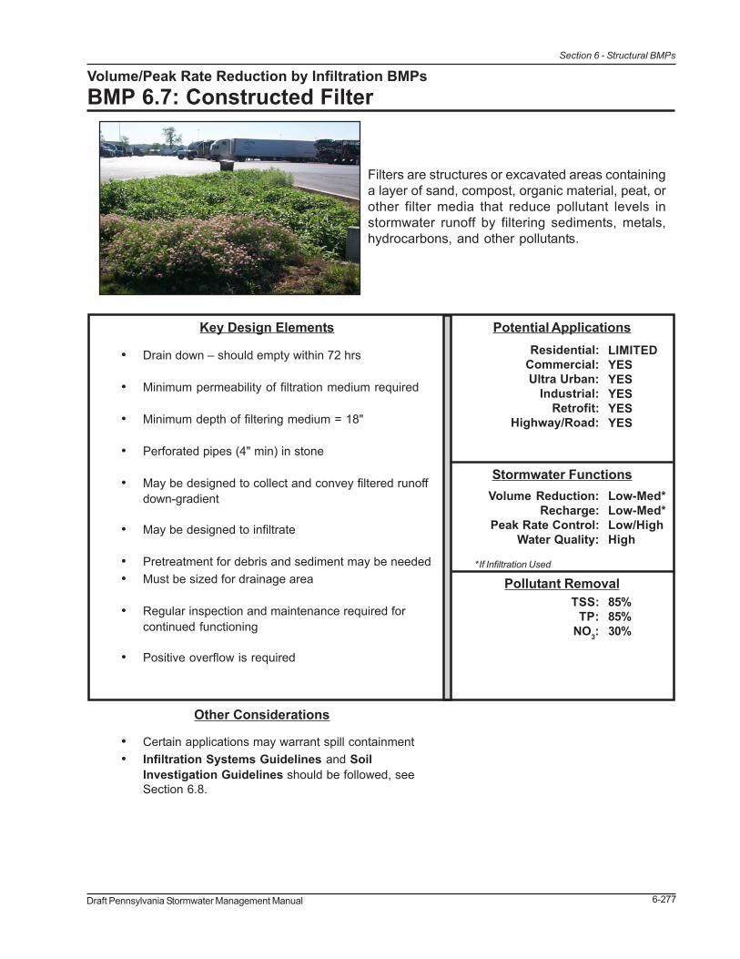
Filters are structures or excavated areas containinga layer of sand, compost, organic material, peat, orother filter media that reduce pollutant levels instormwater runoff by filtering sediments, metals,hydrocarbons, and other pollutants.
Other Considerations
• Certain applications may warrant spill containment• Infiltration Systems Guidelines and Soil
Investigation Guidelines should be followed, seeSection 6.8.
Pollutant Removal85%85%30%
TSS:TP:
NO3:
Stormwater FunctionsLow-Med*Low-Med*Low/HighHigh
Volume Reduction:Recharge:
Peak Rate Control:Water Quality:
*If Infiltration Used
Potential ApplicationsResidential:
Commercial:Ultra Urban:
Industrial:Retrofit:
Highway/Road:
LIMITEDYESYESYESYESYES
Key Design Elements
• Drain down – should empty within 72 hrs
• Minimum permeability of filtration medium required
• Minimum depth of filtering medium = 18"
• Perforated pipes (4" min) in stone
• May be designed to collect and convey filtered runoffdown-gradient
• May be designed to infiltrate
• Pretreatment for debris and sediment may be needed• Must be sized for drainage area
• Regular inspection and maintenance required forcontinued functioning
• Positive overflow is required
6-278 Draft Pennsylvania Stormwater Management Manual
Section 6 - Structural BMPs
Description
A stormwater filter is a structure or excavation filled with material and designed to filter stormwaterrunoff to improve water quality. The filter media may be comprised of materials such as sand, peat,compost, granular activated carbon (GAC), perlite, or other material. In some applications thestormwater runoff flows through an open air, “pretreatment” chamber to allow the large particles anddebris to settle out (sedimentation). Surface vegetation is another good option for pretreatment.The runoff then passes through the filter media where smaller pollutants are filtered out, and iscollected in an under-drain and returned to the conveyance system, receiving waters or infiltratedinto the soil mantle.
Variations
There are a wide variety of Filter Applications, including surface and subsurface, vegetated, perimeter,infiltration, and others. There are also a variety of filter products that may be purchased. Examplesof these variations include:
Surface Non-vegetated Filter
A Surface Non-vegetated Filter is constructed by excavation or by use of a structural container. Thesurface may be covered in sand, peat, gravel, river stone, or similar material.
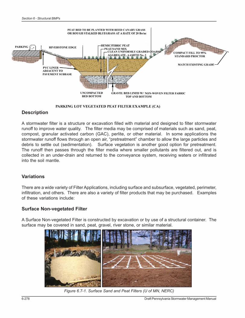
Figure 6.7-1. Surface Sand and Peat Filters (U of MN, NERC)
Draft Pennsylvania Stormwater Management Manual 6-279
Section 6 - Structural BMPs
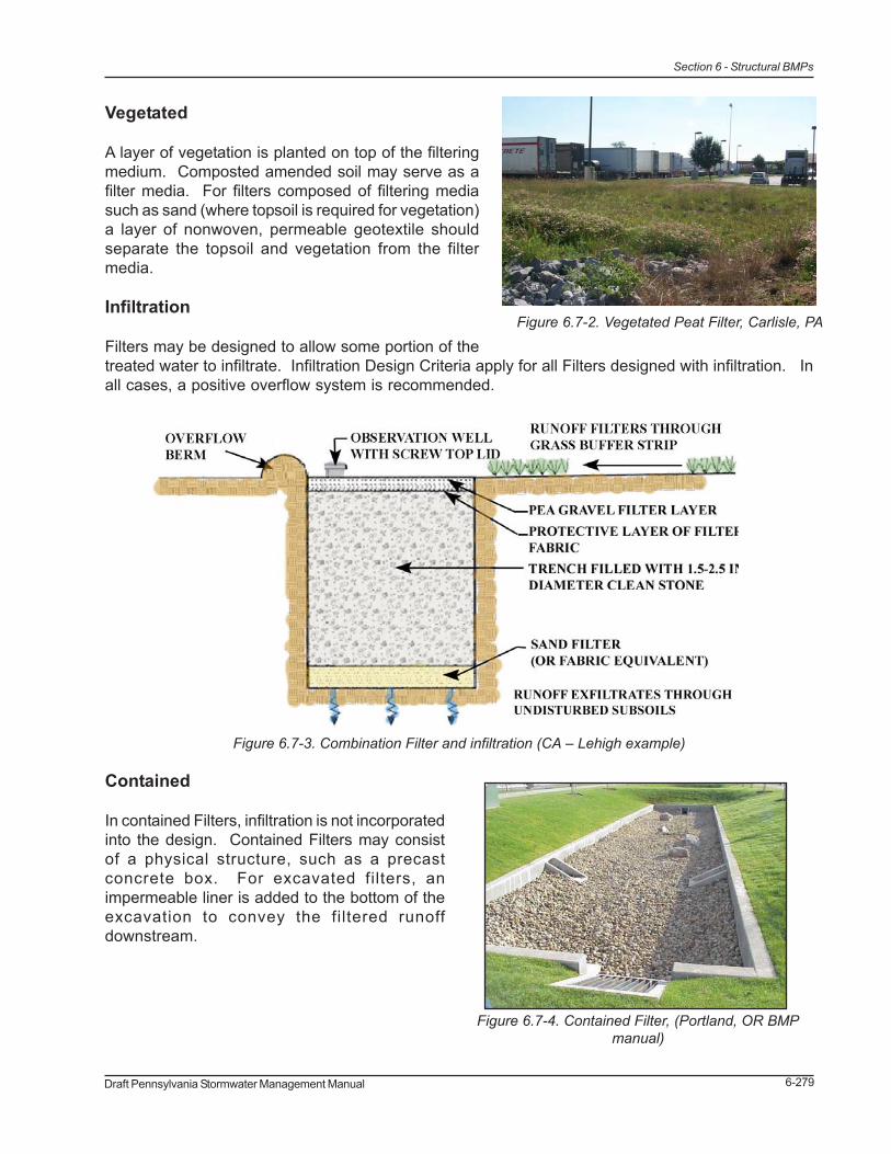
Vegetated
A layer of vegetation is planted on top of the filteringmedium. Composted amended soil may serve as afilter media. For filters composed of filtering mediasuch as sand (where topsoil is required for vegetation)a layer of nonwoven, permeable geotextile shouldseparate the topsoil and vegetation from the filtermedia.
Infiltration
Filters may be designed to allow some portion of thetreated water to infiltrate. Infiltration Design Criteria apply for all Filters designed with infiltration. Inall cases, a positive overflow system is recommended.
Contained
In contained Filters, infiltration is not incorporatedinto the design. Contained Filters may consistof a physical structure, such as a precastconcrete box. For excavated filters, animpermeable liner is added to the bottom of theexcavation to convey the filtered runoffdownstream.
Figure 6.7-2. Vegetated Peat Filter, Carlisle, PA
Figure 6.7-3. Combination Filter and infiltration (CA – Lehigh example)
Figure 6.7-4. Contained Filter, (Portland, OR BMPmanual)
6-280 Draft Pennsylvania Stormwater Management Manual
Section 6 - Structural BMPs
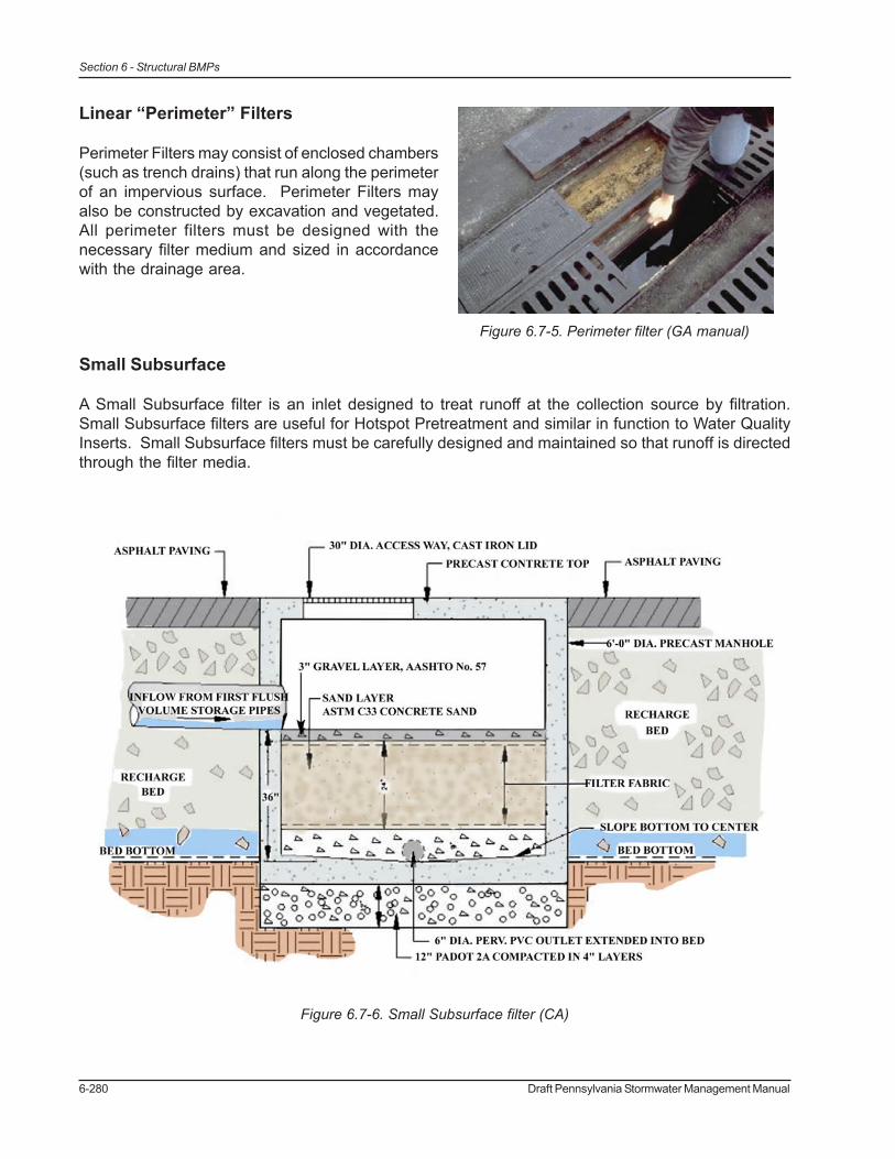
Linear “Perimeter” Filters
Perimeter Filters may consist of enclosed chambers(such as trench drains) that run along the perimeterof an impervious surface. Perimeter Filters mayalso be constructed by excavation and vegetated.All perimeter filters must be designed with thenecessary filter medium and sized in accordancewith the drainage area.
Small Subsurface
A Small Subsurface filter is an inlet designed to treat runoff at the collection source by filtration.Small Subsurface filters are useful for Hotspot Pretreatment and similar in function to Water QualityInserts. Small Subsurface filters must be carefully designed and maintained so that runoff is directedthrough the filter media.
Figure 6.7-6. Small Subsurface filter (CA)
Figure 6.7-5. Perimeter filter (GA manual)
Draft Pennsylvania Stormwater Management Manual 6-281
Section 6 - Structural BMPs
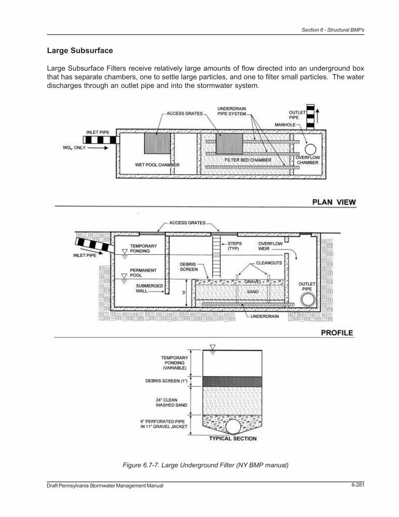
Large Subsurface
Large Subsurface Filters receive relatively large amounts of flow directed into an underground boxthat has separate chambers, one to settle large particles, and one to filter small particles. The waterdischarges through an outlet pipe and into the stormwater system.
Figure 6.7-7. Large Underground Filter (NY BMP manual)

6-282 Draft Pennsylvania Stormwater Management Manual
Section 6 - Structural BMPs
Manufactured Filtration Systems
There are a considerable number of manufactured filtration systems available, some of which alsoincorporate oil/water separators, vortex systems, etc. The Designer should obtain product specificinformation directly from the manufacturer.
Applications
Filters are applicable in urbanized areas of high pollutant loads and are especially applicable wherethere is limited area for construction of other BMPs. Filters may be used as a pretreatment BMPbefore other BMPs such as Wet Ponds or Infiltration systems. Filters may be used in Hot Spot areasfor water quality treatment, and spill containment capabilities may be incorporated into a filter. Examplesof typical areas that benefit from the use of a Filter BMP include:
• Parking lots• Roadways and Highways• Light Industrial sites• Marina areas• Transportation facilities• Fast food and shopping areas• Waste Transfer Stations• Urban Streetscapes
Design Considerations
1. Filters should be sized as per the Control Guideline that applies. All filters must bedesigned so that larger storms may safely overflow or bypass the filter. Flow splitters,multistage chambers, and other devices may be used. A flow splitter may be necessary toallow only a portion of the runoff to enter the filter. This would create an “off-line” filter,where the volume and velocity of runoff entering the filter is controlled. If the filter is “on-line”, excess flow should be designed to bypass filter and continue to another quality BMP.
2. Entering velocity must be controlled. A level spreader may be used to spread flow evenlyacross the filter surface during all storms without eroding the filter material. Parking lotsmay be designed to sheet flow to filters. Small riprap or riverstone edges may be used toreduce velocity and distribute flow.
3. Pretreatment may be necessary in areas with especially high levels of debris, largesediment, etc. Pretreatment may include oil/grit separators, vegetated filter strips, or grassswales. These measures will settle out the large particles and reduce velocity of the runoffbefore it enters the filter.
4. The Filter Media may be a variety of materials and in most cases should have a minimumdepth of 18 inches and a maximum depth of 30 inches, although variations on theseguidelines are acceptable if justified by the designer. Coarser materials allow for morehydraulic conductivity, but finer media filter particles of a smaller size. Sand has been

Draft Pennsylvania Stormwater Management Manual 6-283
Section 6 - Structural BMPs
found to be a good balance between these two criteria (Urbonas), but different types ofmedia remove different pollutants. While sand is a reliable material to remove TSS,(Debusk and Langston, 1997) peat removes slightly more TP, Cu, Cd, and Ni than sand.The Filter Media should have a minimum hydraulic conductivity (k) as follows:
• Sand 3.5 ft/day• Peat 2.5 ft/day• Leaf compost 8.7 ft/day
5. A Gravel Layer at least 6” deep is recommended beneath the Filter Media.
6. Under drain piping should be 4” minimum (diameter) perforated pipes, with a lateralspacing of no more than 10’. A collector pipe can be used, (running perpendicular tolaterals) with a slope of 1%. All underground pipes should have clean-outs accessible fromthe surface.
7. A Drawdown Time of not more than 72 hours is recommended for Filters.
8. The Size of a Filter is determined by the Volume to be treated:
A = V x d / (k x t(h+d))
A = Surface area of Filter (square feet)V = Water volume (cubic feet)d = Depth of Filter Media (min 1.5 ft; max 2.5 ft)t = Drawdown time (days), not to exceed 72 hoursh = Head (average in feet)k = Hydraulic conductivity (ft/day)
9. When a Filter has accumulated sediment in its pore space, its hydraulic conductivity isreduced, and so it its ability to removal pollutants. Maintenance and Inspection areessential for continued performance of a Filter. Based upon inspection, some or allportions of the filter media may require replacement.
10. Filters must be designed with sufficient maintenance access (clean-outs, room forsurface cleaning, etc.). Filters that are visible and simple in design are more likely to bemaintained correctly.
6-284 Draft Pennsylvania Stormwater Management Manual
Section 6 - Structural BMPs
Detailed Stormwater Functions
Volume Reduction CalculationsIf a Filter is designed to include infiltration, the Volume Reduction is a function of the Area of the Filterand infiltration rate. There is minimal volume reduction for Filters that are not designed to infiltrate.
Volume = Infiltration Volume* + Filter VolumeInfiltration Volume = Bottom Area (sf) x Infil. Rate (in/hr) x Drawdown time** (hr)Filter Volume = Area of filter (sf) x Depth (ft) x 20%***
*For filters with infiltration only** Not to exceed 72 hours***For sand, amended soil, compost, peat; Use 20% unless more specific data is available Peak Rate Mitigation CalculationsSee Section 9 for Peak Rate Mitigation methodology which addresses link between volume reductionand peak rate control.
Water Quality ImprovementSee Section 9 for Water Quality Improvement methodology, which addresses pollutant removaleffectiveness of this BMP.
Construction Sequence
1. Permanent Filters should not be installed until the site is stabilized. Excessive sedimentgenerated during construction can clog the Filter and prevent or reduce the anticipatedpost-construction water quality benefits. Stabilize all contributing areas before runoff entersfilters.
2. Structures such as inlet boxes, reinforced concrete boxes, etc. should be installed in
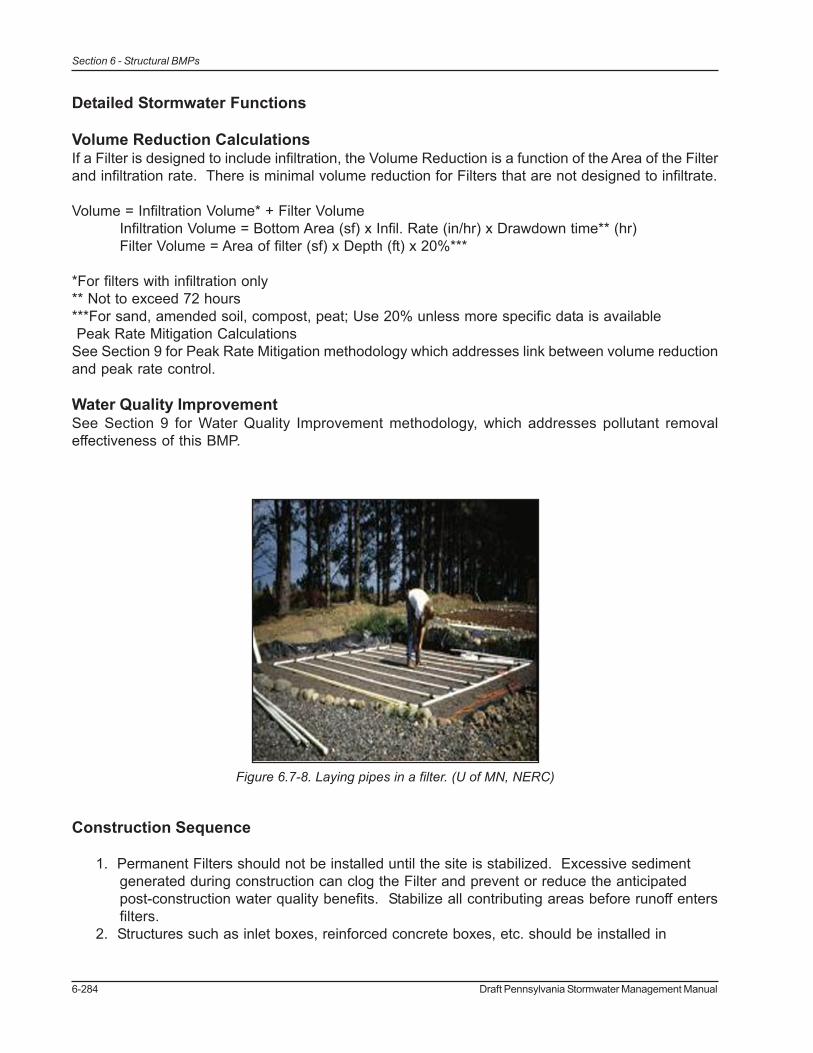
Figure 6.7-8. Laying pipes in a filter. (U of MN, NERC)
Draft Pennsylvania Stormwater Management Manual 6-285
Section 6 - Structural BMPs
accordance with the manufacturers’ or design engineers guidance.3. Excavated filters that infiltrate or structural filters that infiltrate should be excavated in such
a manner as to avoid compaction of the subbase. Structures may be set on a layer ofclean, lightly compacted gravel (such as AASHTO #57).
4. Infiltration Filters should be underlain by a layer of permeable non-woven-geotextile.5. Place underlying gravel/stone in minimum 6 inch lifts and lightly compact. Place underdrain
pipes in gravel during placement.6. Wrap and secure nonwoven geotextile to prevent gravel/stone from clogging with
sediments.7. Lay filtering material. Do not compact.8. Saturate filter media and allow media to drain to properly settle and distribute.9. For vegetated filters, a layer of nonwoven geotextile between non-organic filter media and
planting media is recommended.10. There should be sufficient space (head) between the top of the filtering bed and the
overflow of the Filter to allow for the maximum head designed to be stored before filtration.
Maintenance and Inspection
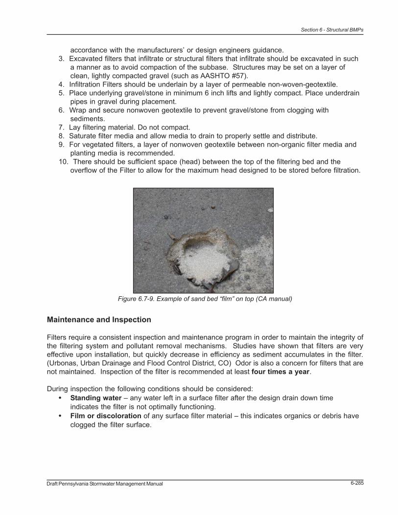
Filters require a consistent inspection and maintenance program in order to maintain the integrity ofthe filtering system and pollutant removal mechanisms. Studies have shown that filters are veryeffective upon installation, but quickly decrease in efficiency as sediment accumulates in the filter.(Urbonas, Urban Drainage and Flood Control District, CO) Odor is also a concern for filters that arenot maintained. Inspection of the filter is recommended at least four times a year.
During inspection the following conditions should be considered:• Standing water – any water left in a surface filter after the design drain down time
indicates the filter is not optimally functioning.• Film or discoloration of any surface filter material – this indicates organics or debris have
clogged the filter surface.
Figure 6.7-9. Example of sand bed “film” on top (CA manual)
6-286 Draft Pennsylvania Stormwater Management Manual
Section 6 - Structural BMPs
Filter Maintenance• Remove trash and debris as necessary• Scrape silt with rakes• Till and aerate filter area• Replace filtering medium if scraping/removal has reduced depth of filtering media
In areas where the potential exists for the discharge and accumulation of toxic pollutants (such asmetals), filter media removed from filters must be handled and disposed of in accordance with allstate and federal regulations.
Winter concerns
Pennsylvania’s winter temperatures go below freezing about four months out of every year, andsurface filtration may not take place as well in the winter. Peat and compost may hold water, freeze,and become impervious on the surface. Design options that allow directly for subsurface dischargeinto the filter media during cold weather may overcome this condition.
Cost Issues
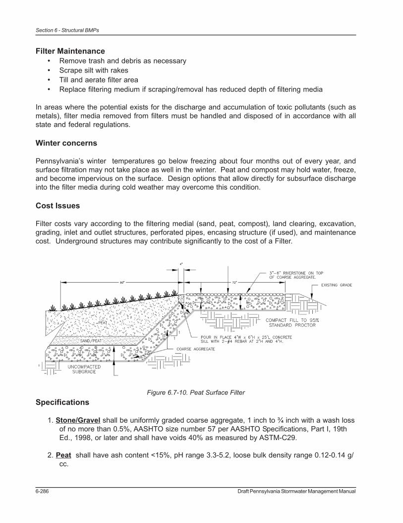
Filter costs vary according to the filtering medial (sand, peat, compost), land clearing, excavation,grading, inlet and outlet structures, perforated pipes, encasing structure (if used), and maintenancecost. Underground structures may contribute significantly to the cost of a Filter.
Specifications
1. Stone/Gravel shall be uniformly graded coarse aggregate, 1 inch to ¾ inch with a wash lossof no more than 0.5%, AASHTO size number 57 per AASHTO Specifications, Part I, 19thEd., 1998, or later and shall have voids 40% as measured by ASTM-C29.
2. Peat shall have ash content <15%, pH range 3.3-5.2, loose bulk density range 0.12-0.14 g/cc.
Figure 6.7-10. Peat Surface Filter

Draft Pennsylvania Stormwater Management Manual 6-287
Section 6 - Structural BMPs
3. Sand shall be ASTM-C-33 (or AASHTO M-6) size (0.02” – 0.04”), concrete sand, clean,medium to fine sand, no organic material.
4. Non-Woven Geotextile shall consist of needled nonwoven polypropylene fibers and meetthe following properties:
a. Grab Tensile Strength (ASTM-D4632) ³ 120 lbsb. Mullen Burst Strength (ASTM-D3786) ³ 225 psic. Flow Rate (ASTM-D4491) ³ 95 gal/min/ft2
d. UV Resistance after 500 hrs (ASTM-D4355) ³ 70%e. Heat-set or heat-calendared fabrics are not permitted
Acceptable types include Mirafi 140N, Amoco 4547, Geotex 451, or approved others.
5. Topsoil See Appendix C
6. Pipe shall be continuously perforated, smooth interior, with a minimum inside diameter of 8-inches. High-density polyethylene (HDPE) pipe shall meet AASHTO M252, Type S orAASHTO M294, Type S.

6-288 Draft Pennsylvania Stormwater Management Manual
Section 6 - Structural BMPs
References
Georgia BMP Manual
University of Minnesota Extension Service, Northeast Regional Correction Center (NERCC)
“Field Evaluation of a Stormwater Sand Filter” Ben R. Urbonas, John T. Doerfer and L. Scott Tuckerwww.udfcd.org/fhn96/flood1.html
“An Evaluation of Filter Media For Treating Stormwater Runoff” Thomas A DeBustk and Michael A.Langston, Benefict Schwegler, Scott Davidson, Fifth Biennial Stormwater Research Conference,November, 1997
“A Denitrification System For Septic Tank Effluent Using Sphagnum Peat Moss” E. S. Winkler, and P.L. M. Veneman
“Stormwater Sand Filter Sizing and Design – A Unit Operations Approach” Urbonas
New York BMP Manual
California BMP Manual
Draft Pennsylvania Stormwater Management Manual 6-289
Section 6 - Structural BMPs
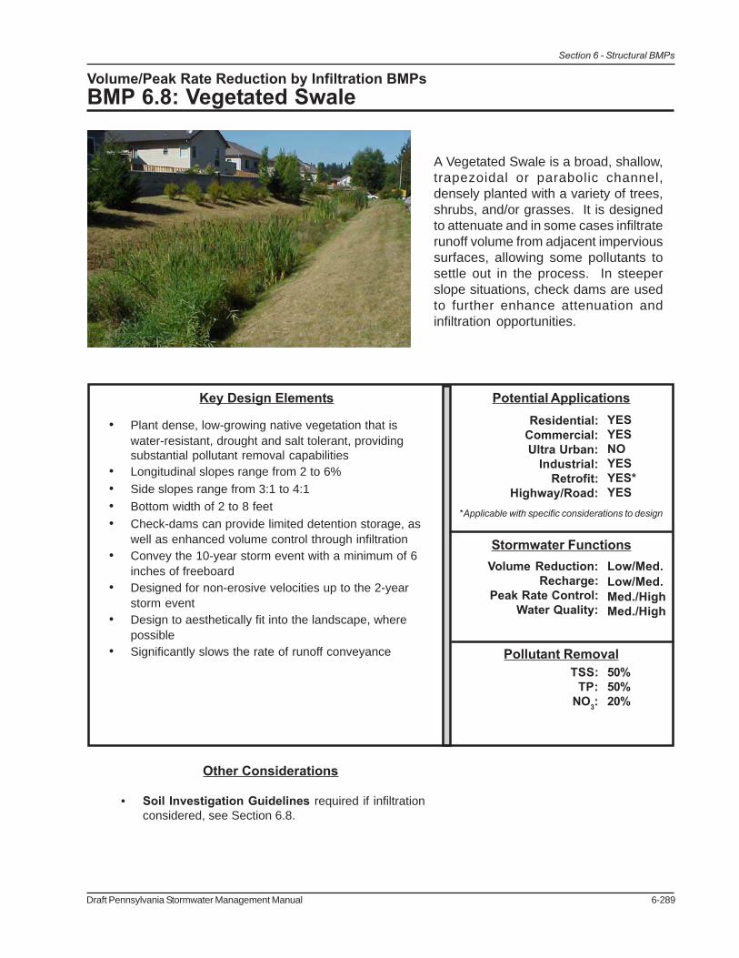
Volume/Peak Rate Reduction by Infiltration BMPsBMP 6.8: Vegetated Swale
A Vegetated Swale is a broad, shallow,trapezoidal or parabolic channel,densely planted with a variety of trees,shrubs, and/or grasses. It is designedto attenuate and in some cases infiltraterunoff volume from adjacent impervioussurfaces, allowing some pollutants tosettle out in the process. In steeperslope situations, check dams are usedto further enhance attenuation andinfiltration opportunities.
Pollutant Removal50%50%20%
TSS:TP:
NO3:
Stormwater FunctionsLow/Med.Low/Med.Med./HighMed./High
Volume Reduction:Recharge:
Peak Rate Control:Water Quality:
Potential ApplicationsResidential:
Commercial:Ultra Urban:
Industrial:Retrofit:
Highway/Road:
YESYESNOYESYES*YES
Key Design Elements
• Plant dense, low-growing native vegetation that iswater-resistant, drought and salt tolerant, providingsubstantial pollutant removal capabilities
• Longitudinal slopes range from 2 to 6%• Side slopes range from 3:1 to 4:1• Bottom width of 2 to 8 feet• Check-dams can provide limited detention storage, as
well as enhanced volume control through infiltration• Convey the 10-year storm event with a minimum of 6
inches of freeboard• Designed for non-erosive velocities up to the 2-year
storm event• Design to aesthetically fit into the landscape, where
possible• Significantly slows the rate of runoff conveyance
*Applicable with specific considerations to design
Other Considerations
• Soil Investigation Guidelines required if infiltrationconsidered, see Section 6.8.
6-290 Draft Pennsylvania Stormwater Management Manual
Section 6 - Structural BMPs
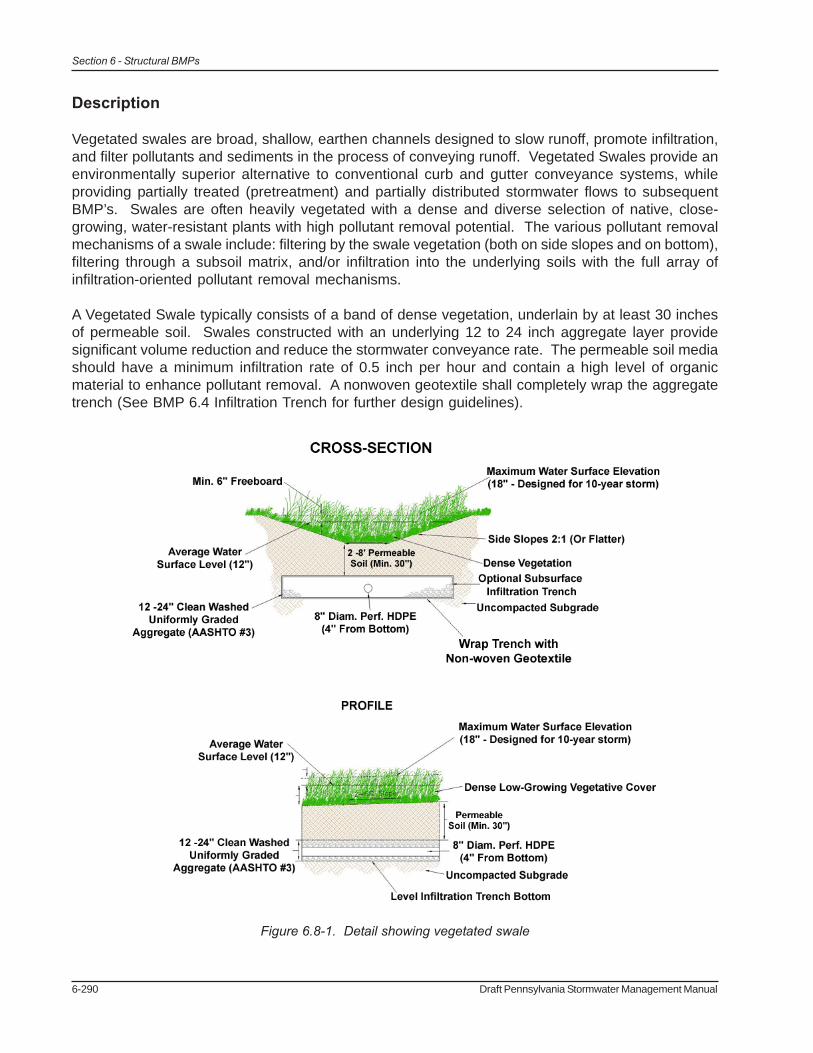
Figure 6.8-1. Detail showing vegetated swale
Description
Vegetated swales are broad, shallow, earthen channels designed to slow runoff, promote infiltration,and filter pollutants and sediments in the process of conveying runoff. Vegetated Swales provide anenvironmentally superior alternative to conventional curb and gutter conveyance systems, whileproviding partially treated (pretreatment) and partially distributed stormwater flows to subsequentBMP’s. Swales are often heavily vegetated with a dense and diverse selection of native, close-growing, water-resistant plants with high pollutant removal potential. The various pollutant removalmechanisms of a swale include: filtering by the swale vegetation (both on side slopes and on bottom),filtering through a subsoil matrix, and/or infiltration into the underlying soils with the full array ofinfiltration-oriented pollutant removal mechanisms.
A Vegetated Swale typically consists of a band of dense vegetation, underlain by at least 30 inchesof permeable soil. Swales constructed with an underlying 12 to 24 inch aggregate layer providesignificant volume reduction and reduce the stormwater conveyance rate. The permeable soil mediashould have a minimum infiltration rate of 0.5 inch per hour and contain a high level of organicmaterial to enhance pollutant removal. A nonwoven geotextile shall completely wrap the aggregatetrench (See BMP 6.4 Infiltration Trench for further design guidelines).
Draft Pennsylvania Stormwater Management Manual 6-291
Section 6 - Structural BMPs
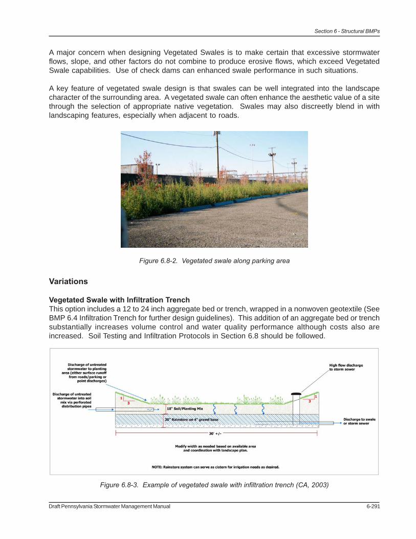
Figure 6.8-2. Vegetated swale along parking area
Figure 6.8-3. Example of vegetated swale with infiltration trench (CA, 2003)
A major concern when designing Vegetated Swales is to make certain that excessive stormwaterflows, slope, and other factors do not combine to produce erosive flows, which exceed VegetatedSwale capabilities. Use of check dams can enhanced swale performance in such situations.
A key feature of vegetated swale design is that swales can be well integrated into the landscapecharacter of the surrounding area. A vegetated swale can often enhance the aesthetic value of a sitethrough the selection of appropriate native vegetation. Swales may also discreetly blend in withlandscaping features, especially when adjacent to roads.
Variations
Vegetated Swale with Infiltration TrenchThis option includes a 12 to 24 inch aggregate bed or trench, wrapped in a nonwoven geotextile (SeeBMP 6.4 Infiltration Trench for further design guidelines). This addition of an aggregate bed or trenchsubstantially increases volume control and water quality performance although costs also areincreased. Soil Testing and Infiltration Protocols in Section 6.8 should be followed.
6-292 Draft Pennsylvania Stormwater Management Manual
Section 6 - Structural BMPs
Figure 6.8-5. Vegetated swale along residential area (Virginia Stormwater Management Handbook)
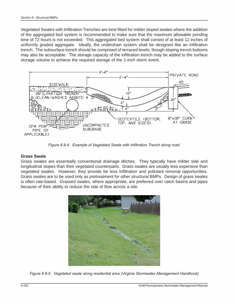
Vegetated Swales with Infiltration Trenches are best fitted for milder sloped swales where the additionof the aggregated bed system is recommended to make sure that the maximum allowable pondingtime of 72 hours is not exceeded. This aggregated bed system shall consist of at least 12 inches ofuniformly graded aggregate. Ideally, the underdrain system shall be designed like an infiltrationtrench. The subsurface trench should be comprised of terraced levels, though sloping trench bottomsmay also be acceptable. The storage capacity of the infiltration trench may be added to the surfacestorage volume to achieve the required storage of the 1-inch storm event.
Grass SwaleGrass swales are essentially conventional drainage ditches. They typically have milder side andlongitudinal slopes than their vegetated counterparts. Grass swales are usually less expensive thanvegetated swales. However, they provide far less infiltration and pollutant removal opportunities.Grass swales are to be used only as pretreatment for other structural BMPs. Design of grass swalesis often rate-based. Grassed swales, where appropriate, are preferred over catch basins and pipesbecause of their ability to reduce the rate of flow across a site.
Figure 6.8-4. Example of Vegetated Swale with Infiltration Trench along road.
Draft Pennsylvania Stormwater Management Manual 6-293
Section 6 - Structural BMPs
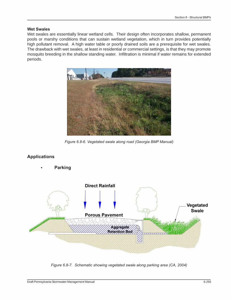
Figure 6.8-6. Vegetated swale along road (Georgia BMP Manual)
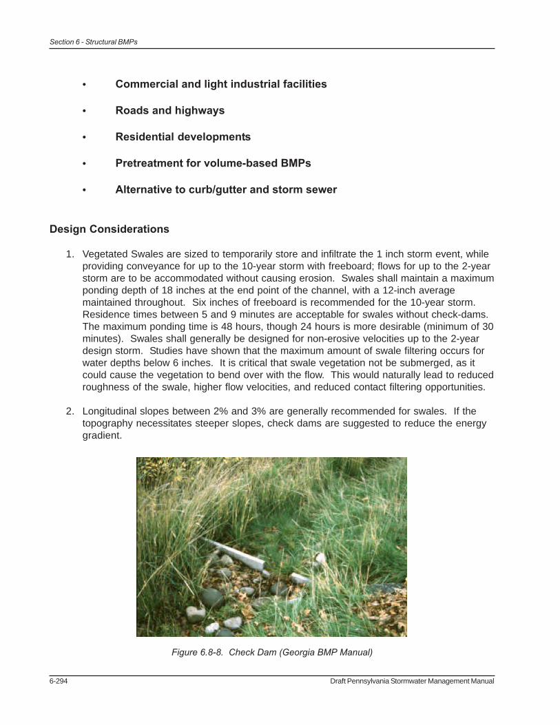
Figure 6.8-7. Schematic showing vegetated swale along parking area (CA, 2004)
Wet SwalesWet swales are essentially linear wetland cells. Their design often incorporates shallow, permanentpools or marshy conditions that can sustain wetland vegetation, which in turn provides potentiallyhigh pollutant removal. A high water table or poorly drained soils are a prerequisite for wet swales.The drawback with wet swales, at least in residential or commercial settings, is that they may promotemosquito breeding in the shallow standing water. Infiltration is minimal if water remains for extendedperiods.
Applications
• Parking
6-294 Draft Pennsylvania Stormwater Management Manual
Section 6 - Structural BMPs
• Commercial and light industrial facilities
• Roads and highways
• Residential developments
• Pretreatment for volume-based BMPs
• Alternative to curb/gutter and storm sewer
Design Considerations
1. Vegetated Swales are sized to temporarily store and infiltrate the 1 inch storm event, whileproviding conveyance for up to the 10-year storm with freeboard; flows for up to the 2-yearstorm are to be accommodated without causing erosion. Swales shall maintain a maximumponding depth of 18 inches at the end point of the channel, with a 12-inch averagemaintained throughout. Six inches of freeboard is recommended for the 10-year storm.Residence times between 5 and 9 minutes are acceptable for swales without check-dams.The maximum ponding time is 48 hours, though 24 hours is more desirable (minimum of 30minutes). Swales shall generally be designed for non-erosive velocities up to the 2-yeardesign storm. Studies have shown that the maximum amount of swale filtering occurs forwater depths below 6 inches. It is critical that swale vegetation not be submerged, as itcould cause the vegetation to bend over with the flow. This would naturally lead to reducedroughness of the swale, higher flow velocities, and reduced contact filtering opportunities.
2. Longitudinal slopes between 2% and 3% are generally recommended for swales. If thetopography necessitates steeper slopes, check dams are suggested to reduce the energygradient.
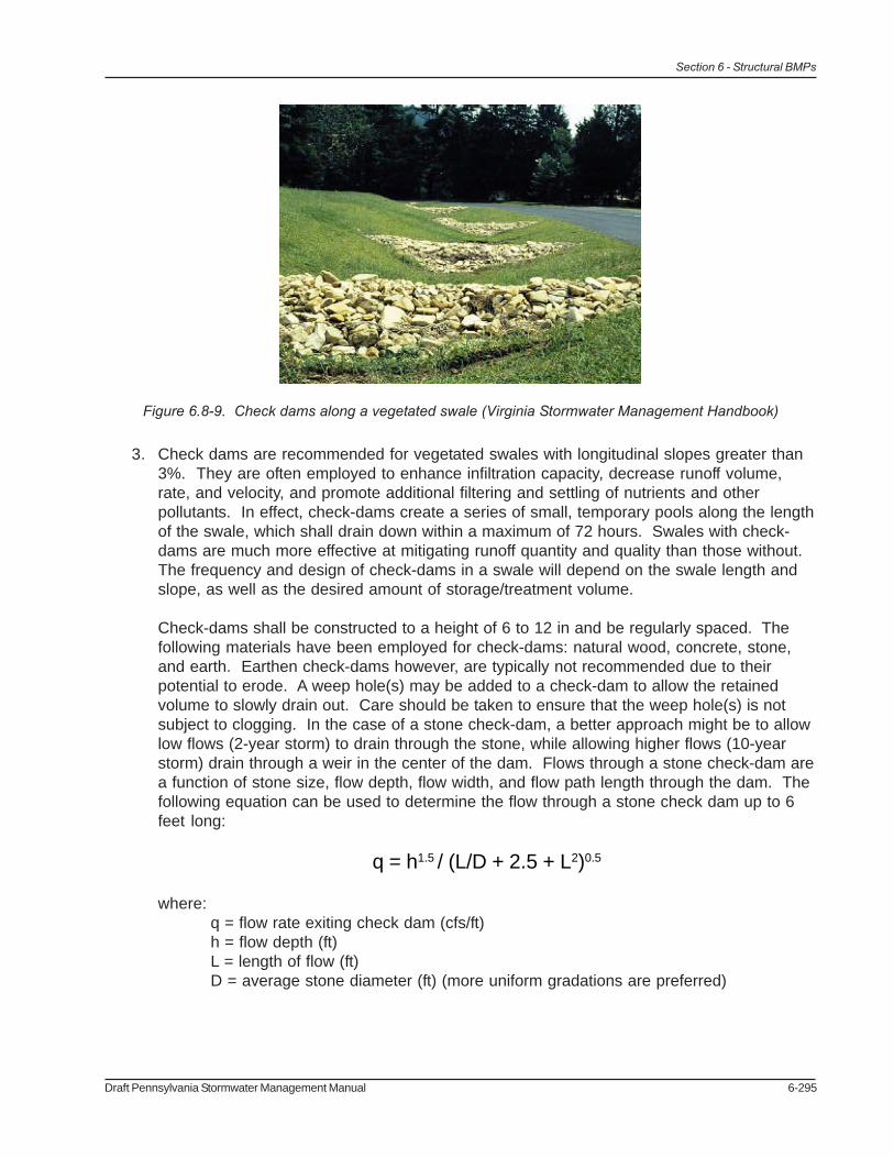
Figure 6.8-8. Check Dam (Georgia BMP Manual)
Draft Pennsylvania Stormwater Management Manual 6-295
Section 6 - Structural BMPs
Figure 6.8-9. Check dams along a vegetated swale (Virginia Stormwater Management Handbook)
3. Check dams are recommended for vegetated swales with longitudinal slopes greater than3%. They are often employed to enhance infiltration capacity, decrease runoff volume,rate, and velocity, and promote additional filtering and settling of nutrients and otherpollutants. In effect, check-dams create a series of small, temporary pools along the lengthof the swale, which shall drain down within a maximum of 72 hours. Swales with check-dams are much more effective at mitigating runoff quantity and quality than those without.The frequency and design of check-dams in a swale will depend on the swale length andslope, as well as the desired amount of storage/treatment volume.
Check-dams shall be constructed to a height of 6 to 12 in and be regularly spaced. Thefollowing materials have been employed for check-dams: natural wood, concrete, stone,and earth. Earthen check-dams however, are typically not recommended due to theirpotential to erode. A weep hole(s) may be added to a check-dam to allow the retainedvolume to slowly drain out. Care should be taken to ensure that the weep hole(s) is notsubject to clogging. In the case of a stone check-dam, a better approach might be to allowlow flows (2-year storm) to drain through the stone, while allowing higher flows (10-yearstorm) drain through a weir in the center of the dam. Flows through a stone check-dam area function of stone size, flow depth, flow width, and flow path length through the dam. Thefollowing equation can be used to determine the flow through a stone check dam up to 6feet long:
q = h1.5 / (L/D + 2.5 + L2)0.5
where:q = flow rate exiting check dam (cfs/ft)h = flow depth (ft)L = length of flow (ft)D = average stone diameter (ft) (more uniform gradations are preferred)

6-296 Draft Pennsylvania Stormwater Management Manual
Section 6 - Structural BMPs
For low flows, check-dam geometry and swale width are actually more influential on flowthan stone size. The average flow length through a check-dam as a function of flow depthcan be determined by the following equation:
L = (ss) x (2d – h)where:ss = check dam side slope (maximum 2:1)d = height of dam (ft)h = flow depth (ft)
When swale flows overwhelm the flow-through capacity of a stone check-dam, the top ofthe dam shall act as a standard weir (use standard weir equation). (Though a principalspillway, 6 inches below the height of the dam, may also be required depending on flowconditions.) If the check-dam is designed to be overtopped, appropriate selection ofaggregate will ensure stability during flooding events. In general, one stone size for a damis recommended for ease of construction. However, two or more stone sizes may be used,provided a larger stone (e.g. R-4) is placed on the downstream side, since flows areconcentrated at the exit channel of the weir. Several feet of smaller stone (e.g. AASHTO#57) can then be placed on the upstream side. Smaller stone may also be moreappropriate at the base of the dam for constructability purposes.
4. The effectiveness of a vegetated swale is directly related to the contributing land use, thesize of the drainage area, the soil type, slope, drainage area imperviousness, proposedvegetation, and the swale dimensions. Use of natural low points in the topography may besuited for swale location, as are natural drainage courses although infiltration capabilitymay also be reduced in these situations. The topography of a site shall allow for thedesign of a swale with sufficiently mild slope and flow capacity. Swales are impractical inareas of extreme (very flat or steep) slopes. Of course, adequate space is required forvegetated swales. Swales are ideal as an alternative to curbs and gutters along parkinglots and along small roads in gently sloping terrain.
Siting of vegetated swales should take into account the location and function of other sitefeatures (buffers, undisturbed natural areas, etc.). Siting should also attempt toaesthetically fit the swale into the landscape as much as possible. Sharp bends in swalesshould be avoided.
Implementing vegetated swales is challenging when development density exceeds fourdwelling units per acre, in which case the number of driveway culverts often increases tothe point where swales essentially become broken-pipe systems.
Where possible, construct swales in areas of uncompacted cut. Avoid constructing sideslopes in fill material. Fill slopes can be prone to erosion and/or structural damage byburrowing animals.
5. Soil Investigation and Percolation Testing Required when infiltration is planned (seeSection 6.8).
6. Guidelines for Infiltration Systems must be met (see Section 6.8).

Draft Pennsylvania Stormwater Management Manual 6-297
Section 6 - Structural BMPs
7. Swales are typically most effective, when treating an area of 1 to 2 acres althoughvegetated swales can be used to treat and convey runoff from an area of 5 to 10 acres insize. Swales serving greater than 10-acre drainage areas will still provide a lesser degreewater quality treatment, unless special provisions are made to manage the increased flows.
8. Runoff can be directed into Vegetated Swales either as concentrated flows or as lateralsheet flow drainage. Both are acceptable provided sufficient stabilization or energydissipation is included (see #6). If flow is to be directed into a swale via curb cuts, providea 2 to 3 inch drop at the interface of pavement and swale. Curb cuts should be at least 12inches wide to prevent clogging and should be spaced appropriately.
9. Vegetated swales are sometimes used as pretreatment devices for other structural BMP’s,especially roadway runoff. However, when swales themselves are intended to effectivelytreat runoff from highly impervious surfaces, pretreatment measures are recommended toenhance swale performance. Pretreatment can dramatically extend the functional life ofany BMP, as well as increase its pollutant removal efficiency by settling out some of theheavier sediments. This treatment volume is typically obtained by installing check dams atpipe inlets and/or driveway crossings. Other pretreatment options include a vegetated filterstrip, a sediment forebay (or plunge pool) for concentrated flows, or a pea graveldiaphragm (or alternative) with a 6-inch drop where parking lot sheet flow is directed into aswale.
10. The soil base for a vegetated swale must provide stability and adequate support forproposed vegetation. When the existing site soil is deemed unsuitable (clayey, rocky,coarse sands, etc.) to support dense vegetation, replacing with approximately 12 inches ofloamy or sandy soils is recommended. In general, alkaline soils should be used to furtherreduce and retain metals. Swale soils shall also be well-drained. If the infiltration capacityis compromised during construction, the first several feet shall be removed and replacedwith a blend of topsoil and sand to promote infiltration and biological growth.
11. Swales are most efficient when their cross-sections are parabolic or trapezoidal in nature.Swale side slopes are best within a range of 3:1 to 4:1 and shall never be greater than 2:1for ease of maintenance and side inflow from sheet flow.
12. To ensure the filtration capacity and proper performance of swales, the bottom widthstypically range from 2 to 8 feet. Wider channels are feasible only when obstructions suchas berms or walls are employed to prohibit braiding or uncontrolled sub-channel formation.The maximum bottom width to depth ratio for a trapezoidal swale should be 12:1.
13. Ideal swale vegetation shall consist of a dense and diverse selection of close-growing,water-resistant plants whose growing season preferably corresponds to the wet season.For swales that are not part of a regularly irrigated landscaped area, drought tolerantvegetation should be considered as well. Vegetation shall be selected at an early stage inthe design process, with well-defined pollution control goals in mind. Selected vegetationmust be able to thrive at the specific site and therefore should be chosen carefully (SeeAppendix B). Use of native plant species is strongly advised, as is avoidance of invasiveplant species. Swale vegetation must also be salt tolerant, if winter road maintenanceactivities are expected to contribute salt/chlorides.

6-298 Draft Pennsylvania Stormwater Management Manual
Section 6 - Structural BMPs
Common Name Scientific Name Notes
Alkai saltgrass Puccinellia distans Cool, good for wet, saline swales Fowl bluegrass Poa palustris Cool, good for wet swales Canada bluejoint Calamagrostis canadensis Cool, good for wet swales Creeping bentgrass Agrostis palustris Cool, good for wet swales, salt tolerant Red fescue Festuca rubra Cool, not for wet swales Redtop Agrostis gigantea Cool, good for wet swales Rough bluegrass Poa trivialis Cool, good for wet, shady swales Switchgrass Panicum virgatum Warm, good for wet swales, some salt tolerance Wildrye Elymus virginicus/rigarius Cool, good for shady, wet swales
Notes: These grasses are sod forming and can withstand frequent inundation, and are ideal for the swale or grass channel environment. A few are also salt-tolerant. Cool refers to cool season grasses that grow during the cooler temperatures of spring and fall. Warm refers to warm season grasses that grow most vigorously during the hot, mid-summer months.
Table: 6.8-1. Commonly used vegetation in swales (New Jersey BMP Manual, 2004)
By landscaping with trees along side slopes, swales can be easily and aestheticallyintegrated into the overall site design without unnecessary loss of usable space. Animportant consideration however, is that tree plantings allow enough light to pass andsustain a dense ground cover. When the trees have reached maturity, they should provideenough shade to markedly reduce high temperatures in swale runoff.
14. Check the temporary and permanent stability of the swale using the standards outlined inthe Pennsylvania Erosion and Sediment Pollution Control Program Manual. Swales shallconvey either 2.75 cfs/acre or the calculated peak discharge from a 10-year storm event.In most cases, the permissible velocity design method may be used for channel linings.The allowable shear method is also acceptable. Flow capacity, velocity, and design depthin swales are generally calculated by Manning’s equation.
Prior to establishment of vegetation, a swale is particularly vulnerable to scour and erosionand therefore its seed bed must be protected with temporary erosion control, such as strawmatting, compost blankets, or fiberglass roving. Most vendors will provide informationabout the Manning’s ‘n’ value and will specify the maximum permissible velocity orallowable unit tractive force for the lining material.
The post-vegetation establishment capacity of the swale shall also be confirmed.Permanent turf reinforcement may supersede temporary reinforcement on sites where notexceeding the maximum permissible velocity is problematic. If driveways or roads cross aswale, culvert capacity may supersede Manning’s equation for determination of design flowdepth. In these cases, the culvert should be checked to establish that the backwaterelevation would not exceed the banks of the swale. If the culverts are to discharge to aminimum tailwater condition, the exit velocity for the culvert should be evaluated for designconditions. If the maximum permissible velocity is exceeded at the culvert outlet, energy
Draft Pennsylvania Stormwater Management Manual 6-299
Section 6 - Structural BMPs
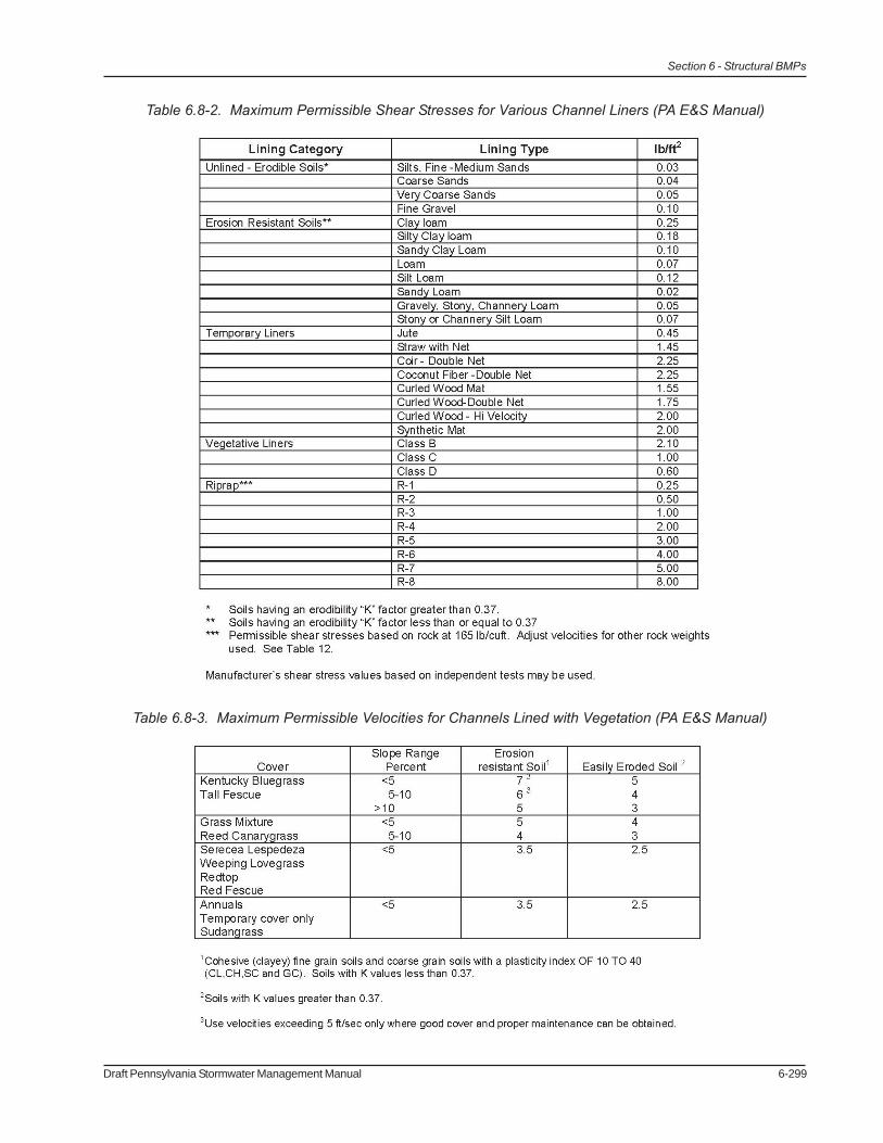
Table 6.8-2. Maximum Permissible Shear Stresses for Various Channel Liners (PA E&S Manual)
Table 6.8-3. Maximum Permissible Velocities for Channels Lined with Vegetation (PA E&S Manual)
6-300 Draft Pennsylvania Stormwater Management Manual
Section 6 - Structural BMPs
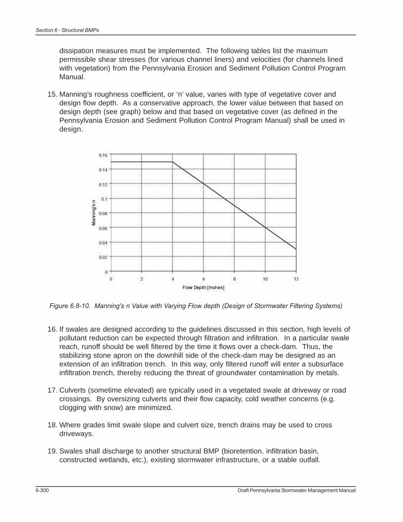
Figure 6.8-10. Manning's n Value with Varying Flow depth (Design of Stormwater Filtering Systems)
dissipation measures must be implemented. The following tables list the maximumpermissible shear stresses (for various channel liners) and velocities (for channels linedwith vegetation) from the Pennsylvania Erosion and Sediment Pollution Control ProgramManual.
15. Manning’s roughness coefficient, or ‘n’ value, varies with type of vegetative cover anddesign flow depth. As a conservative approach, the lower value between that based ondesign depth (see graph) below and that based on vegetative cover (as defined in thePennsylvania Erosion and Sediment Pollution Control Program Manual) shall be used indesign.
16. If swales are designed according to the guidelines discussed in this section, high levels ofpollutant reduction can be expected through filtration and infiltration. In a particular swalereach, runoff should be well filtered by the time it flows over a check-dam. Thus, thestabilizing stone apron on the downhill side of the check-dam may be designed as anextension of an infiltration trench. In this way, only filtered runoff will enter a subsurfaceinfiltration trench, thereby reducing the threat of groundwater contamination by metals.
17. Culverts (sometime elevated) are typically used in a vegetated swale at driveway or roadcrossings. By oversizing culverts and their flow capacity, cold weather concerns (e.g.clogging with snow) are minimized.
18. Where grades limit swale slope and culvert size, trench drains may be used to crossdriveways.
19. Swales shall discharge to another structural BMP (bioretention, infiltration basin,constructed wetlands, etc.), existing stormwater infrastructure, or a stable outfall.
Draft Pennsylvania Stormwater Management Manual 6-301
Section 6 - Structural BMPs
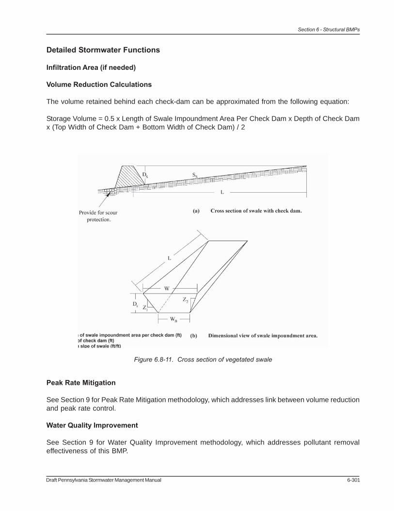
Figure 6.8-11. Cross section of vegetated swale
Detailed Stormwater Functions
Infiltration Area (if needed)
Volume Reduction Calculations
The volume retained behind each check-dam can be approximated from the following equation:
Storage Volume = 0.5 x Length of Swale Impoundment Area Per Check Dam x Depth of Check Damx (Top Width of Check Dam + Bottom Width of Check Dam) / 2
Peak Rate Mitigation
See Section 9 for Peak Rate Mitigation methodology, which addresses link between volume reductionand peak rate control.
Water Quality Improvement
See Section 9 for Water Quality Improvement methodology, which addresses pollutant removaleffectiveness of this BMP.
6-302 Draft Pennsylvania Stormwater Management Manual
Section 6 - Structural BMPs
Construction Sequence
1. Begin vegetated swale construction only when the upgradient site has been sufficientlystabilized and temporary erosion and sediment control measures are in place. Vegetatedswales should be constructed and stabilized very early in the construction schedule,preferably before mass earthwork and paving increase the rate and volume of runoff.(Erosion and sediment control methods shall adhere to the Pennsylvania Department ofEnvironmental Protection’s Erosion and Sediment Pollution Control Program Manual,March 2000 or latest edition.)
2. Rough grade the vegetated swale. Equipment shall avoid excessive compaction and/orland disturbance. Excavating equipment should operate from the side of the swale andnever on the bottom. If excavation leads to substantial compaction of the subgrade (wherean infiltration trench is not proposed), 18 inches shall be removed and replaced with ablend of topsoil and sand to promote infiltration and biological growth. At the very least,topsoil shall be thoroughly deep plowed into the subgrade in order to penetrate thecompacted zone and promote aeration and the formation of macropores. Following this,the area should be disked prior to final grading of topsoil.
3. Construct check dams, if required.
4. Fine grade the vegetated swale. Accurate grading is crucial for swales. Even the smallestnon-conformities may compromise flow conditions.
5. Seed and vegetate according to final planting list. Plant the swale at a time of the yearwhen successful establishment without irrigation is most likely. However, temporaryirrigation may be needed in periods of little rain or drought. Vegetation should beestablished as soon as possible to prevent erosion and scour.
6. Concurrent with #7, stabilize freshly seeded swales with appropriate temporary orpermanent soil stabilization methods, such as erosion control matting or blankets. Erosioncontrol for seeded swales shall be required for at least the first 75 days following the firststorm event of the season. If runoff velocities are high, consider sodding the swale ordiverting runoff until vegetation is fully established. (Erosion and sediment control methodsshall adhere to the Pennsylvania Department of Environmental Protection’s Erosion andSediment Pollution Control Program Manual, March 2000 or latest edition.)
7. Once the swale is sufficiently stabilized, remove temporary erosion and sediment controls.It is very important that the swale be stabilized before receiving upland stormwater flow.
8. Follow maintenance guidelines, as discussed below.
Note: If a vegetated swale is used for runoff conveyance during construction, it must beregraded and reseeded immediately after construction and stabilization has occurred. Anydamaged areas must be fully restored to ensure future functionality of the swale.

Draft Pennsylvania Stormwater Management Manual 6-303
Section 6 - Structural BMPs
Maintenance Issues
Compared to other stormwater management measures, the required upkeep of vegetated swales isrelatively low. In general, maintenance strategies for swales focus on sustaining both the hydraulicand pollutant removal efficiency of the channel, as well as maintaining a dense vegetative cover.Experience has proven that proper maintenance activities ensure the functionality of vegetated swalesfor many years. The following schedule of inspection and maintenance activities is recommended:
Maintenance activities to be done annually or 48 hours after every major storm event(semiannually for the first year):
• Inspect and correct erosion problems, damage to vegetation, and sediment and debrisaccumulation (when > 3 in at any spot or covers vegetation)
• Inspect vegetation on side slopes for erosion and formation of rills or gullies, correct asneeded
• Inspect for pools of standing water; dewater and discharge to a sanitary sewer at anapproved location
• Mow and trim vegetation to ensure safety, aesthetics, proper swale operation, or tosuppress weeds and invasive vegetation; dispose of cuttings in a local composting facility;mow only when swale is dry to avoid rutting
• Inspect for litter; remove prior to mowing
• Inspect for uniformity in cross-section and longitudinal slope, correct as needed
• Inspect swale inlet (curb cuts, pipes, etc.) and outlet for signs of erosion or blockage,correct as needed
Maintenance activities to be done as needed:
• Plant alternative grass species in the event of unsuccessful establishment
• Reseed bare areas; install appropriate erosion control measures when native soil isexposed or erosion channels are forming
• Rototill and replant swale if draw down time is less than 48 hours
• Inspect and correct check dams when signs of altered water flow (channelization,obstructions, etc.) is identified
• Water during dry periods, fertilize, and apply pesticide only when absolutely necessary
Most of the above maintenance activities are reasonably within the ability of individual homeowners.More intensive swales (i.e. more substantial vegetation, check dams, etc.) may warrant more intensivemaintenance duties and should be vested with a responsible agency. A legally binding and enforceable

6-304 Draft Pennsylvania Stormwater Management Manual
Section 6 - Structural BMPs
Swale Underground Pipe Curb & Gutter
Construction Cost (per linear foot)
$4.50 - $8.50 (from seed) $15 – 20 (from sod)
$2 per foot per inch of diameter (e.g. a 12” pipe would cost $24 per linear foot)
$13 – 15
Annual O&M cost (per linear foot)
$0.75 No data No data
Total annual cost (per linear foot)
$1 (from seed) $2 (from sod)
No data No data
Lifetime (years) 50 20
Table 6.8-4 Cost Comparison showing vegetated swale to pipe, curb, and gutter (Source: Bay AreaStormwater Management Agencies Association, June 1997).
maintenance agreement between the facility owner and the local review authority might be warrantedto ensure sustained maintenance execution. Winter conditions also necessitate additionalmaintenance concerns, which include the following:
• Inspect swale immediately after the spring melt, remove residuals (e.g. sand) and replacedamaged vegetation without disturbing remaining vegetation.
• If roadside or parking lot runoff is directed to the swale, mulching and/or soil aeration/manipulation may be required in the spring to restore soil structure and moisture capacityand to reduce the impacts of deicing agents.
• Use nontoxic, organic deicing agents, applied either as blended, magnesium chloride-based liquid products or as pretreated salt.
• Use salt-tolerant vegetation in swales.
Cost Issues
As with all other BMPs, the cost of installing and maintaining Vegetated Swales varies widely withdesign variability, local labor/material rates, real estate value, and contingencies. In general, VegetatedSwales are considered relatively low cost control measures. Moreover, experience has shown thatVegetated Swales provide a cost-effective alternative to traditional curbs and gutters, includingassociated underground storm sewers. The following table compares the cost of a typical vegetatedswale (15 ft top width) with the cost of traditional conveyance elements.
It is important to note that the costs listed above are strictly estimates and shall be used for designpurposes only. Also, these costs do not include the cost of activities such as clearing, grubbing,leveling, filling, and sodding (if required). The Southeastern Wisconsin Regional Planning Commission(SEWRPC, 1991) reported that actual costs, which do include these activities, may range from $8.50

Draft Pennsylvania Stormwater Management Manual 6-305
Section 6 - Structural BMPs
to $50.00 per linear foot depending on swale depth and bottom width. When all pertinent constructionactivities are considered, it is still likely that the cost of vegetated swale installation is less than that oftraditional conveyance elements. When annual operation and maintenance costs are consideredhowever, swales may prove the more expensive option, though they typically have a much longerlifespan.
Specifications
The following specifications are provided for information purposes only. These specifications includeinformation on acceptable materials for typical applications, but are by no means exclusive or limiting.The designer is responsible for developing detailed specifications for individual design projects inaccordance with the project conditions.
1. Swale Soil shall be USCS class ML (Inorganic silts and very fine sands, rock flour, silty orclayey fine sands with slight plasticity), SM (Silty sands, poorly graded sand-silt mixtures),SW (Well-graded sands, gravelly sands, little or no fines) or SC (Clayey sands, poorlygraded sand-clay mixtures). The first three of these designations are preferred for swalesin cold climates. In general, soil with a higher percent organic content is preferred.
2. Swale Sand shall be ASTM C-33 fine aggregate concrete sand (0.02 in to 0.04 in).
3. Check dams constructed of natural wood shall be 6 in to 12 in diameter and notched asnecessary. The following species are acceptable: Black Locust, Red Mulberry, Cedars,Catalpa, White Oak, Chestnut Oak, Black Walnut. The following species are notacceptable, as they can rot over time: Ash, Beech, Birch, Elm, Hackberry, hemlock,Hickories, Maples, Red and Black Oak, Pines, Poplar, Spruce, Sweetgum, and Willow. Anearthen check dam shall be constructed of sand, gravel, and sandy loam to encouragegrass cover (Sand: ASTM C-33 fine aggregate concrete sand 0.02 in to 0.04 in, Gravel:AASHTO M-43 0.5 in to 1.0 in). A stone check dam shall be constructed of R-4 rip rap, orequivalent.
4. Develop a native planting mix. (see Appendix B)
5. Topsoil amended with compost (see Appendix C)
6. If infiltration trench is proposed, see BMP 6.4 Infiltration Trench for specifications.
6-306 Draft Pennsylvania Stormwater Management Manual
Section 6 - Structural BMPs
References
Alameda Countywide Clean Water Program (ACCWP). “Grassy Swales.” Catalog of Control Measures.<http://www.oaklandpw.com/creeks/pdf/Grassy_Swales.pdf>
AMEC Earth and Environmental Center for Watershed Protection et al. Georgia StormwaterManagement Manual. 2001.
California Stormwater Quality Association. California Stormwater Best Management PracticesHandbook: New Development and Redevelopment. 2003.
Caraco and Claytor. Stormwater BMP Design Supplement for Cold Climates. 1997.
City of Portland Environmental Services. City of Portland Stormwater Management Manual: Revision#2. 2002.
Center for Watershed Protection and Maryland Department of the Environment. 2000 MarylandStormwater Design Manual. Baltimore, MD: 2000.
Claytor, R.A. and T.R. Schuler. Design of Stormwater Filtering Systems. Center for WatershedProtection. Silver Spring, MD: 1996.
Colwell, S. R. et al. Characterization of Performance Predictors and Evaluation of Mowing Practicesin Biofiltration Swales. 2000.
DURMM Manual 2002
Fletcher, T., Wong, T., and Breen, P. “Chapter 9 – Buffer Strips, Vegetated Swales and BioretentionSystems.” Australian Runoff Quality (Draft). University of New Castle – Australia.
Lichten, K. “Grassy Swales.” BMP Fact Sheets. Bay Area Stormwater Management AgenciesAssociation (BASMAA). 1997.
Maine Department of Transportation. Maine Department of Transportation BMP Manual for Erosionand Sedimentation Control. 1992.
North Central Texas Council of Governments. Stormwater Best Management Practices: A Menu ofManagement Plan Options for Small MS4s in North Central Texas. 2002.
Schueler, T. et al. A Current Assessment of Urban Best Management Practices: Techniques forReducing Nonpoint Source Pollution in the Coastal Zone. 1992.
United States Environmental Protection Agency (USEPA). “Post-Construction Storm WaterManagement in New Development & Redevelopment.” National Pollutant Discharge EliminationSystem (NPDES). <http://cfpub1.epa.gov/npdes/stormwater/menuofbmps/post_8.cfm>
United States Environmental Protection Agency (USEPA). Storm Water Technology Fact Sheet:Vegetated Swales (EPA 832-F-99-006). 1999.

Draft Pennsylvania Stormwater Management Manual 6-307
Section 6 - Structural BMPs
Vermont Agency of Natural Resources. The Vermont Stormwater Management Manual. 2002.
Virginia Stormwater Management Handbook, Volumes 1 and 2, First Edition, 1999

6-308 Draft Pennsylvania Stormwater Management Manual
Section 6 - Structural BMPs
Draft Pennsylvania Stormwater Management Manual 6-309
Section 6 - Structural BMPs
Volume/Peak Rate Reduction by Infiltration BMPsBMP 6.9: Vegetated Filter Strip
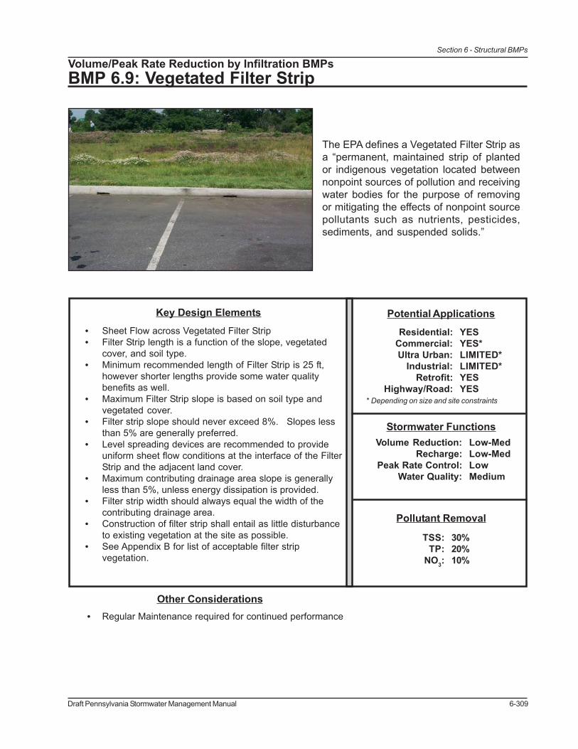
The EPA defines a Vegetated Filter Strip asa “permanent, maintained strip of plantedor indigenous vegetation located betweennonpoint sources of pollution and receivingwater bodies for the purpose of removingor mitigating the effects of nonpoint sourcepollutants such as nutrients, pesticides,sediments, and suspended solids.”
Key Design Elements• Sheet Flow across Vegetated Filter Strip• Filter Strip length is a function of the slope, vegetated
cover, and soil type.• Minimum recommended length of Filter Strip is 25 ft,
however shorter lengths provide some water qualitybenefits as well.
• Maximum Filter Strip slope is based on soil type andvegetated cover.
• Filter strip slope should never exceed 8%. Slopes lessthan 5% are generally preferred.
• Level spreading devices are recommended to provideuniform sheet flow conditions at the interface of the FilterStrip and the adjacent land cover.
• Maximum contributing drainage area slope is generallyless than 5%, unless energy dissipation is provided.
• Filter strip width should always equal the width of thecontributing drainage area.
• Construction of filter strip shall entail as little disturbanceto existing vegetation at the site as possible.
• See Appendix B for list of acceptable filter stripvegetation.
• Regular Maintenance required for continued performance
Other Considerations
Pollutant Removal
30%20%10%
TSS:TP:
NO3:
Potential Applications
* Depending on size and site constraints
Residential:Commercial:Ultra Urban:
Industrial:Retrofit:
Highway/Road:
YESYES*LIMITED*LIMITED*YESYES
Stormwater FunctionsLow-MedLow-MedLowMedium
Volume Reduction:Recharge:
Peak Rate Control:Water Quality:
6-310 Draft Pennsylvania Stormwater Management Manual
Section 6 - Structural BMPs
Description
Filter strips are gently sloping, densely vegetated areas that filter, slow, and infiltrate sheet flowingstormwater. Filter strips are best utilized to treat runoff from roads and highways, roof downspouts,small parking lots, and pervious surfaces. In highly impervious areas, they are generally notrecommended as “stand alone” features, but as pretreatment systems for other BMPs, such asInfiltration Trenches or Bioretention Areas. Filter Strips are primarily designed to reduced TSSlevels, however pollutant levels of hydrocarbons, heavy metals, and nutrients may also be reduced.Pollutant removal mechanisms include sedimentation, filtration, absorption, infiltration, biologicaluptake, and microbial activity. Depending on hydrologic soil group, vegetative cover type, slope, andlength, a filter strip can allow for a modest reduction in runoff volume through infiltration.
The vegetation for Filter Strips may be comprised of:• Turf Grasses• Meadow grasses, shrubs, and native vegetation, including trees• Indigenous areas of woods and vegetation.
Filter strips may be comprised of a variety of trees, shrubs, and native vegetation to add aestheticvalue as well as water quality benefits. The use of turf grasses will increase the required length ofthe filter strip, as compared to other vegetation options. The use of indigenous vegetated areas thathave surface features that disperse runoff is encouraged, as the use of these areas will also reduceoverall site disturbance and soil compaction. Runoff must be distributed so that erosive conditionscannot develop.
The vegetation in Filter Strips must be dense and healthy. Indigenous wooded areas should have ahealthy layer of leaf mulch or duff. Indigenous areas that have surface features that concentrate floware not acceptable.
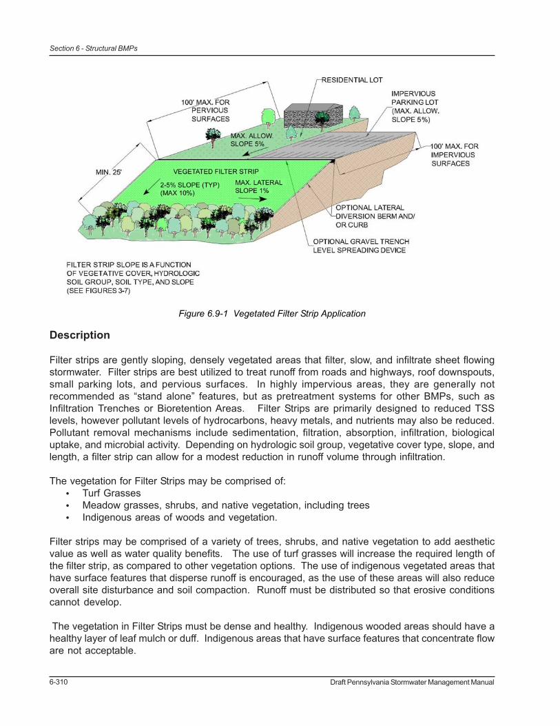
Figure 6.9-1 Vegetated Filter Strip Application
Draft Pennsylvania Stormwater Management Manual 6-311
Section 6 - Structural BMPs
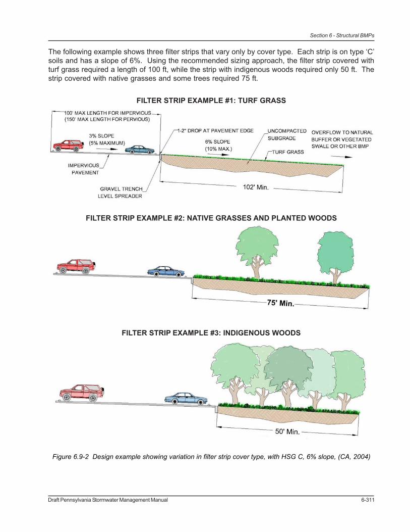
The following example shows three filter strips that vary only by cover type. Each strip is on type ‘C’soils and has a slope of 6%. Using the recommended sizing approach, the filter strip covered withturf grass required a length of 100 ft, while the strip with indigenous woods required only 50 ft. Thestrip covered with native grasses and some trees required 75 ft.
Figure 6.9-2 Design example showing variation in filter strip cover type, with HSG C, 6% slope, (CA, 2004)
FILTER STRIP EXAMPLE #1: TURF GRASS
FILTER STRIP EXAMPLE #2: NATIVE GRASSES AND PLANTED WOODS
FILTER STRIP EXAMPLE #3: INDIGENOUS WOODS
6-312 Draft Pennsylvania Stormwater Management Manual
Section 6 - Structural BMPs
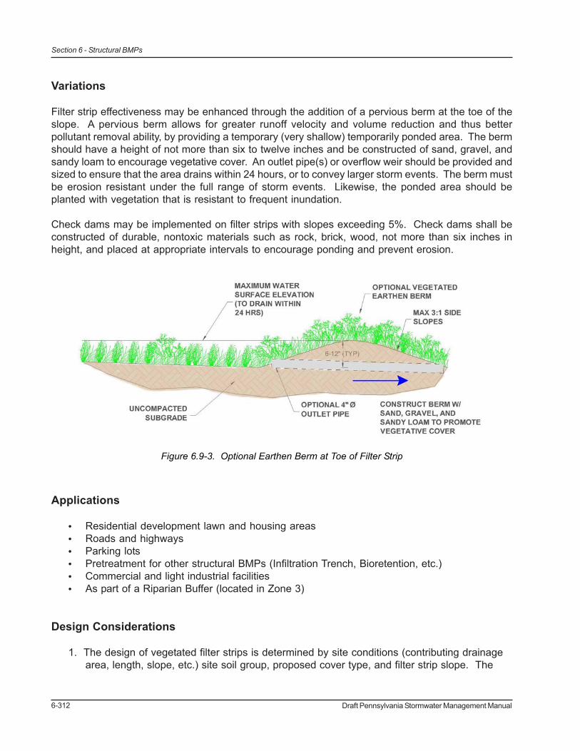
Variations
Filter strip effectiveness may be enhanced through the addition of a pervious berm at the toe of theslope. A pervious berm allows for greater runoff velocity and volume reduction and thus betterpollutant removal ability, by providing a temporary (very shallow) temporarily ponded area. The bermshould have a height of not more than six to twelve inches and be constructed of sand, gravel, andsandy loam to encourage vegetative cover. An outlet pipe(s) or overflow weir should be provided andsized to ensure that the area drains within 24 hours, or to convey larger storm events. The berm mustbe erosion resistant under the full range of storm events. Likewise, the ponded area should beplanted with vegetation that is resistant to frequent inundation.
Check dams may be implemented on filter strips with slopes exceeding 5%. Check dams shall beconstructed of durable, nontoxic materials such as rock, brick, wood, not more than six inches inheight, and placed at appropriate intervals to encourage ponding and prevent erosion.
Applications
• Residential development lawn and housing areas• Roads and highways• Parking lots• Pretreatment for other structural BMPs (Infiltration Trench, Bioretention, etc.)• Commercial and light industrial facilities• As part of a Riparian Buffer (located in Zone 3)
Design Considerations
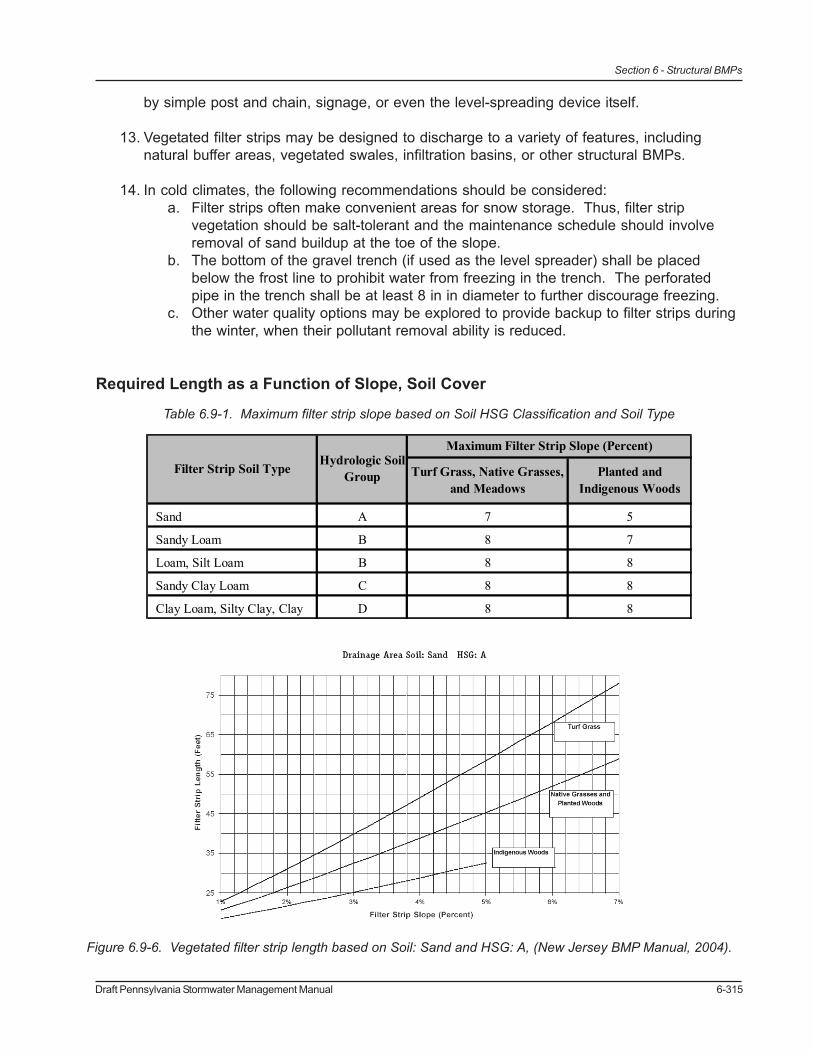
1. The design of vegetated filter strips is determined by site conditions (contributing drainagearea, length, slope, etc.) site soil group, proposed cover type, and filter strip slope. The
Figure 6.9-3. Optional Earthen Berm at Toe of Filter Strip
Draft Pennsylvania Stormwater Management Manual 6-313
Section 6 - Structural BMPs
filter length can be determined from the appropriate graph (see Figures 6.9-x through 6.9-x).
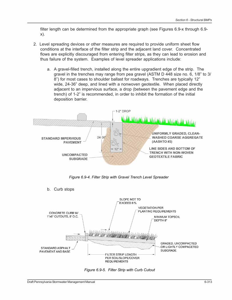
2. Level spreading devices or other measures are required to provide uniform sheet flowconditions at the interface of the filter strip and the adjacent land cover. Concentratedflows are explicitly discouraged from entering filter strips, as they can lead to erosion andthus failure of the system. Examples of level spreader applications include:
a. A gravel-filled trench, installed along the entire upgradient edge of the strip. Thegravel in the trenches may range from pea gravel (ASTM D 448 size no. 6, 1/8” to 3/8”) for most cases to shoulder ballast for roadways. Trenches are typically 12”wide, 24-36” deep, and lined with a nonwoven geotextile. When placed directlyadjacent to an impervious surface, a drop (between the pavement edge and thetrench) of 1-2” is recommended, in order to inhibit the formation of the initialdeposition barrier.
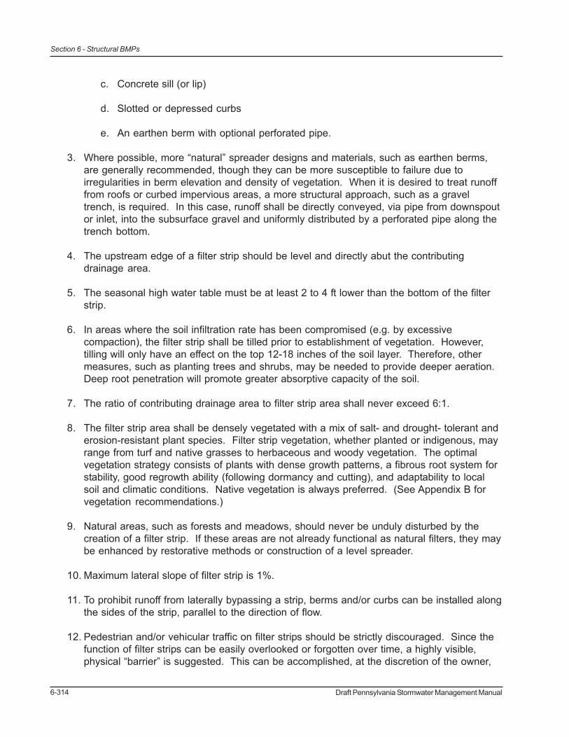
b. Curb stops
Figure 6.9-4. Filter Strip with Gravel Trench Level Spreader
Figure 6.9-5. Filter Strip with Curb Cutout
6-314 Draft Pennsylvania Stormwater Management Manual
Section 6 - Structural BMPs
c. Concrete sill (or lip)
d. Slotted or depressed curbs
e. An earthen berm with optional perforated pipe.
3. Where possible, more “natural” spreader designs and materials, such as earthen berms,are generally recommended, though they can be more susceptible to failure due toirregularities in berm elevation and density of vegetation. When it is desired to treat runofffrom roofs or curbed impervious areas, a more structural approach, such as a graveltrench, is required. In this case, runoff shall be directly conveyed, via pipe from downspoutor inlet, into the subsurface gravel and uniformly distributed by a perforated pipe along thetrench bottom.
4. The upstream edge of a filter strip should be level and directly abut the contributingdrainage area.
5. The seasonal high water table must be at least 2 to 4 ft lower than the bottom of the filterstrip.
6. In areas where the soil infiltration rate has been compromised (e.g. by excessivecompaction), the filter strip shall be tilled prior to establishment of vegetation. However,tilling will only have an effect on the top 12-18 inches of the soil layer. Therefore, othermeasures, such as planting trees and shrubs, may be needed to provide deeper aeration.Deep root penetration will promote greater absorptive capacity of the soil.
7. The ratio of contributing drainage area to filter strip area shall never exceed 6:1.
8. The filter strip area shall be densely vegetated with a mix of salt- and drought- tolerant anderosion-resistant plant species. Filter strip vegetation, whether planted or indigenous, mayrange from turf and native grasses to herbaceous and woody vegetation. The optimalvegetation strategy consists of plants with dense growth patterns, a fibrous root system forstability, good regrowth ability (following dormancy and cutting), and adaptability to localsoil and climatic conditions. Native vegetation is always preferred. (See Appendix B forvegetation recommendations.)
9. Natural areas, such as forests and meadows, should never be unduly disturbed by thecreation of a filter strip. If these areas are not already functional as natural filters, they maybe enhanced by restorative methods or construction of a level spreader.
10. Maximum lateral slope of filter strip is 1%.
11. To prohibit runoff from laterally bypassing a strip, berms and/or curbs can be installed alongthe sides of the strip, parallel to the direction of flow.
12. Pedestrian and/or vehicular traffic on filter strips should be strictly discouraged. Since thefunction of filter strips can be easily overlooked or forgotten over time, a highly visible,physical “barrier” is suggested. This can be accomplished, at the discretion of the owner,
Draft Pennsylvania Stormwater Management Manual 6-315
Section 6 - Structural BMPs
by simple post and chain, signage, or even the level-spreading device itself.
13. Vegetated filter strips may be designed to discharge to a variety of features, includingnatural buffer areas, vegetated swales, infiltration basins, or other structural BMPs.
14. In cold climates, the following recommendations should be considered:a. Filter strips often make convenient areas for snow storage. Thus, filter strip
vegetation should be salt-tolerant and the maintenance schedule should involveremoval of sand buildup at the toe of the slope.
b. The bottom of the gravel trench (if used as the level spreader) shall be placedbelow the frost line to prohibit water from freezing in the trench. The perforatedpipe in the trench shall be at least 8 in in diameter to further discourage freezing.
c. Other water quality options may be explored to provide backup to filter strips duringthe winter, when their pollutant removal ability is reduced.
Required Length as a Function of Slope, Soil Cover
Sand A 7 5
Sandy Loam B 8 7
Loam, Silt Loam B 8 8
Sandy Clay Loam C 8 8
Clay Loam, Silty Clay, Clay D 8 8
Filter Strip Soil TypeHydrologic Soil
Group
Maximum Filter Strip Slope (Percent)
Turf Grass, Native Grasses, and Meadows
Planted and Indigenous Woods
Table 6.9-1. Maximum filter strip slope based on Soil HSG Classification and Soil Type
Figure 6.9-6. Vegetated filter strip length based on Soil: Sand and HSG: A, (New Jersey BMP Manual, 2004).
6-316 Draft Pennsylvania Stormwater Management Manual
Section 6 - Structural BMPs
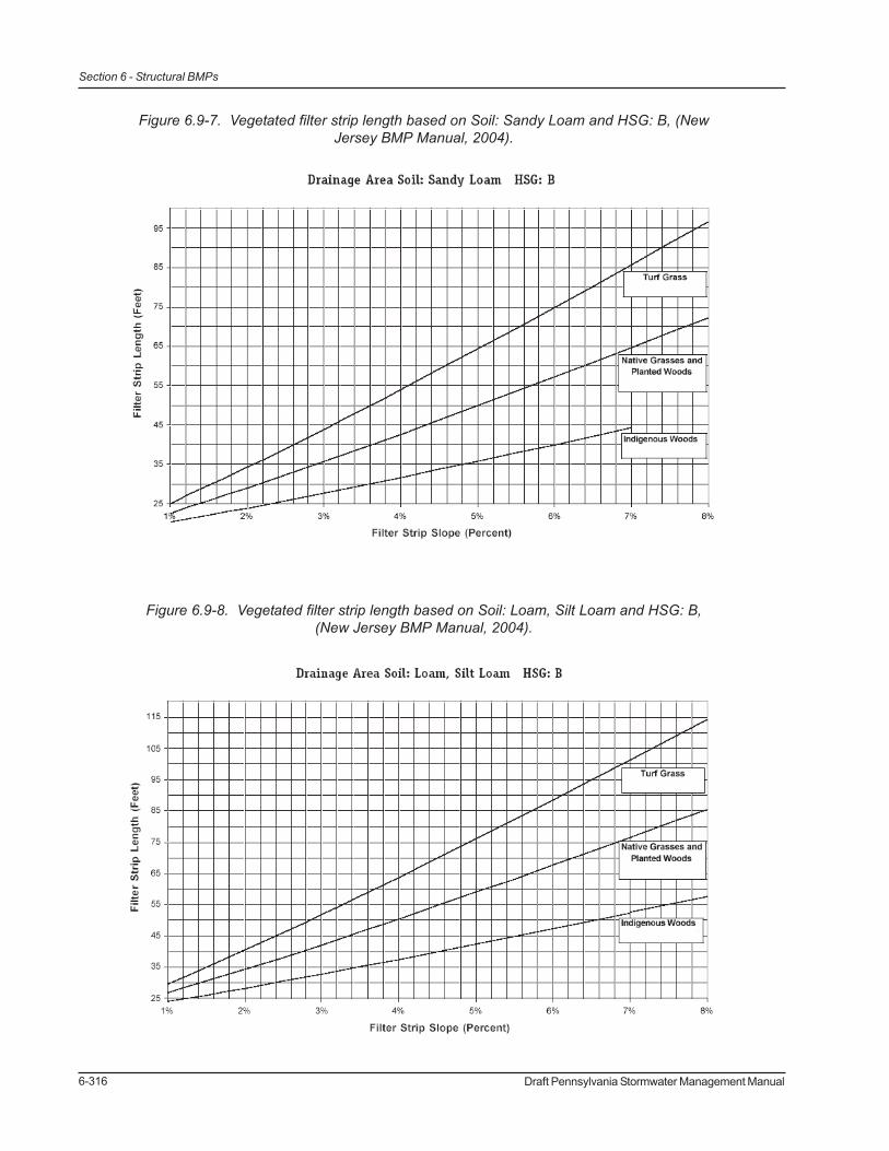
Figure 6.9-7. Vegetated filter strip length based on Soil: Sandy Loam and HSG: B, (NewJersey BMP Manual, 2004).
Figure 6.9-8. Vegetated filter strip length based on Soil: Loam, Silt Loam and HSG: B,(New Jersey BMP Manual, 2004).
Draft Pennsylvania Stormwater Management Manual 6-317
Section 6 - Structural BMPs
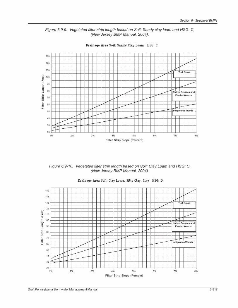
Figure 6.9-9. Vegetated filter strip length based on Soil: Sandy clay loam and HSG: C,(New Jersey BMP Manual, 2004).
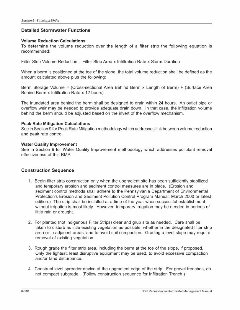
Figure 6.9-10. Vegetated filter strip length based on Soil: Clay Loam and HSG: C,(New Jersey BMP Manual, 2004).
6-318 Draft Pennsylvania Stormwater Management Manual
Section 6 - Structural BMPs
Detailed Stormwater Functions
Volume Reduction CalculationsTo determine the volume reduction over the length of a filter strip the following equation isrecommended:
Filter Strip Volume Reduction = Filter Strip Area x Infiltration Rate x Storm Duration
When a berm is positioned at the toe of the slope, the total volume reduction shall be defined as theamount calculated above plus the following:
Berm Storage Volume = (Cross-sectional Area Behind Berm x Length of Berm) + (Surface AreaBehind Berm x Infiltration Rate x 12 hours)
The inundated area behind the berm shall be designed to drain within 24 hours. An outlet pipe oroverflow weir may be needed to provide adequate drain down. In that case, the infiltration volumebehind the berm should be adjusted based on the invert of the overflow mechanism.
Peak Rate Mitigation CalculationsSee in Section 9 for Peak Rate Mitigation methodology which addresses link between volume reductionand peak rate control.
Water Quality ImprovementSee in Section 9 for Water Quality Improvement methodology which addresses pollutant removaleffectiveness of this BMP.
Construction Sequence
1. Begin filter strip construction only when the upgradient site has been sufficiently stabilizedand temporary erosion and sediment control measures are in place. (Erosion andsediment control methods shall adhere to the Pennsylvania Department of EnvironmentalProtection’s Erosion and Sediment Pollution Control Program Manual, March 2000 or latestedition.) The strip shall be installed at a time of the year when successful establishmentwithout irrigation is most likely. However, temporary irrigation may be needed in periods oflittle rain or drought.
2. For planted (not indigenous Filter Strips) clear and grub site as needed. Care shall betaken to disturb as little existing vegetation as possible, whether in the designated filter striparea or in adjacent areas, and to avoid soil compaction. Grading a level slope may requireremoval of existing vegetation.
3. Rough grade the filter strip area, including the berm at the toe of the slope, if proposed.Only the lightest, least disruptive equipment may be used, to avoid excessive compactionand/or land disturbance.
4. Construct level spreader device at the upgradient edge of the strip. For gravel trenches, donot compact subgrade. (Follow construction sequence for Infiltration Trench.)

Draft Pennsylvania Stormwater Management Manual 6-319
Section 6 - Structural BMPs
5. Fine grade the filter strip area. Accurate grading is crucial for filter strips. Even the smallestirregularities may compromise sheet flow conditions.
6. Seed or sod, as desired. Plant more substantial vegetation, such as trees and shrubs, ifproposed. If sod is proposed, place tiles tightly enough to avoid gaps and stagger the endsto prevent channelization along the strip. Use a roller on sod to prevent air pocketsbetween the sod and soil from forming.
7. Concurrent with #6, stabilize seeded filter strips with appropriate permanent soil stabilizationmethods, such as erosion control matting or blankets. Erosion control for seeded filterstrips shall be required for at least the first 75 days following the first storm event of theseason.
8. Once the filter strip is sufficiently stabilized, remove temporary erosion and sedimentcontrols. It is very important that filter strip vegetation be fully established before receivingupland stormwater flow. One full growing season is the recommended minimum time forestablishment.
9. Follow maintenance guidelines, as discussed below.
Note: When and if a filter strip is used for temporary sediment control, it must be regraded andreseeded immediately after construction and stabilization has occurred.
Maintenance Issues
As with other vegetated BMPs, filter strips must be properly maintained to ensure their effectiveness.In particular, it is critical that sheet flow conditions and infiltration are sustained throughout the life ofthe filter strip. Field observations of strips in more urban settings show that their effectiveness candeteriorate due to lack of maintenance, inadequate design/location, and poor vegetative cover.Compared with other vegetated BMPs, filter strips require only minimal maintenance efforts, many ofwhich may overlap with standard landscaping demands.
Vegetated filter strip components that receive or trap sediment and debris shall be inspected forclogging, density of vegetation, damage by foot or vehicular traffic, excessive accumulations, andchannelization. Inspections shall be made on a quarterly basis for the first two years followinginstallation, and then on a biannual basis thereafter. Inspections shall also be made after everystorm event greater than 1 in during the establishment period Guidance information, usually inwritten manual form, for operating and maintaining filter strips shall be provided to all facility ownersand tenants. Facility owners are encouraged to keep an inspection log, where they can record allinspection dates, observations, and maintenance activities.
Sediment and debris shall be routinely removed (but never less than biannually), or upon observation,when buildup exceeds 2 in in depth in either the strip itself or the level spreader. If erosion is observed,measures shall be taken to improve the level spreader or other dispersion method to address thesource of erosion. Rills and gullies observed along the strip may be filled with topsoil, stabilized witherosion control matting, and either seeded or sodded, as desired. For channels less than 12 in wide,filling with crushed gravel, which allows grass to creep in over time, is acceptable. For wider channels,

6-320 Draft Pennsylvania Stormwater Management Manual
Section 6 - Structural BMPs
i.e. greater than 12 in, regrading and reseeding may be necessary. (Small bare areas may onlyrequire overseeding.) Regrading may also be required when pools of standing water are observedalong the slope. (In no case shall standing water be tolerated for longer than 48-72 hours.) If checkdams are proposed, they shall be inspected for cracks, rot, structural damage, obstructions, or anyother factors that cause altered flow patterns or channelization. Inlets or sediment sumps that drainto filter strips shall be cleaned periodically or as needed.
Sediment shall be removed when the filter strip is thoroughly dry. Trash and debris removed from thesite shall be deposited only at suitable disposal/recycling sites and must comply with applicable local,state, and federal waste regulations. In the case where a filter strip is used for sediment control, itshall be regraded and reseeded immediately after construction has concluded.
Maintaining a vigorous vegetative cover on a filter strip is critical for maximizing pollutant removalefficiency and erosion prevention. Grass cover shall be mowed, with low ground pressure equipment,as needed to maintain a height of 4-6 in. Mowing shall be done only when the soil is dry, in order toprevent tracking damage to vegetation, soil compaction, and flow concentrations. Generally speaking,grasses should be allowed to grow as high as possible, but mowed frequently enough to avoidtroublesome insects or noxious weeds. Fall mowing should be controlled to a grass height of 6 in, toprovide adequate wildlife winter habitat. When and where cutting is desired for aesthetic reasons, ahigh blade setting shall be used.
If vegetative cover is not fully established within the designated time, it shall be replaced with analternative species. (It is standard practice to contractually require the contractor to replace deadvegetation.) Unwanted or invasive growth shall be removed on an annual basis. Biweekly inspectionsare recommended for at least the first growing season, or until the vegetation is permanentlyestablished. Once the vegetation is established, inspections of health, diversity, and density shall beperformed at least twice per year, during both the growing and non-growing season. Vegetativecover should be sustained at 85% and reestablished if damage greater than 50% is observed.Whenever possible, deficiencies in vegetation are to be mollified without the use of fertilizers orpesticides. These treatment options, as well as any other methods used to achieve optimum vegetativehealth, may only be used under special circumstances and if they do not compromise the functionalityof the filter strip.
Two other maintenance recommendations involve soil aeration and drain down time. If a filter stripexhibits signs of poor drainage and/or vegetative cover, periodic soil aeration may be required. Inaddition, depending on soil characteristics, the strip may require periodic liming. The design andmaintenance plan of filter strips, especially those with flow obstructions such as berms and checkdams, must specify the approximate time it should normally take for the system to “drain down” themaximum design storm runoff volume. Post-rainfall inspections shall include evaluations of the filter’sactual drain down time compared to the specified time. If significant differences (either increase ordecrease) are observed, or if the 72 hour maximum time is exceeded, strip characteristics such assoils, vegetation, and groundwater levels must be reevaluated. Measures shall be taken to establish,or reestablish as the case may be, the specified drain down time of the system.
Cost Issues
The real cost of filter strips is the land they require. When unused land is readily available at a site,filter strips may prove a sensible and cost-effective approach. However, where land costs are at a

Draft Pennsylvania Stormwater Management Manual 6-321
Section 6 - Structural BMPs
premium (i.e. not readily available), this practice may prove cost-prohibitive in the end. The cost ofestablishing a filter strip itself is relatively minor. Of course, the cost is even less when an existinggrass or meadow area is identified as a possible filter strip area before development begins.
The cost of filter strips includes grading, sodding (when applicable), installation of vegetation (trees,shrubs, etc.), the construction of a level spreader, and the construction of a pervious berm, if proposed.Depending on whether seed or sod is applied, not to mention enhanced vegetation use or designvariations (such as check dams), construction costs may range anywhere from $0 (assuming thearea was to be grassed regardless of use as treatment) to $50,000 per acre. The annual cost ofmaintaining filter strips (mowing, weeding, inspection, litter removal, etc.) generally runs from $100 to$1400 per acre and in fact, may overlap with standard landscape maintenance costs. Maintenancecosts are highly variable, as they are a function of frequency and local labor rates.
Specifications
The following specifications are provided for information purposes only. These specifications includeinformation on acceptable materials for typical applications, but are by no means exclusive or limiting.The designer is responsible for developing detailed specifications for individual design projects inaccordance with the project conditions.
1. Topsoil – See Appendix C
2. Vegetation – See Appendix B
3. Erosion and Sediment Control components shall conform to the Pennsylvania Departmentof Environmental Protection’s Erosion and Sediment Pollution Control Program Manual,March 2000 or latest edition.
For a gravel trench level spreader:
6. Pipe shall be continuously perforated, smooth interior, high-density polyethylene (HDPE)with a minimum inside diameter of 8-inches. The pipe shall meet AASHTO M252, Type Sor AASHTO M294, Type S.
7. Stone for infiltration trenches shall be 2-inch to 1-inch uniformly graded coarse aggregate,with a wash loss of no more than 0.5%, AASHTO size number 3 per AASHTOSpecifications, Part I, 19th Ed., 1998, or later and shall have voids ≥ 35% as measured byASTM-C29.
Pea gravel (clean bank-run gravel) may also be used. Pea gravel shall meet ASTM D 448and be sized as per No.6 or 1/8” to 3/8”.
8. Non-Woven Geotextile shall consist of needled non-woven polypropylene fibers and meetthe following properties:
a. Grab Tensile Strength (ASTM-D4632) ≥ 120 lbsb. Mullen Burst Strength (ASTM-D3786) ≥ 225 psic. Flow Rate (ASTM-D4491) ≥ 95 gal/min/ft2

6-322 Draft Pennsylvania Stormwater Management Manual
Section 6 - Structural BMPs
d. UV Resistance after 500 hrs (ASTM-D4355) ≥ 70%e. Heat-set or heat-calendared fabrics are not permitted
Acceptable types include Mirafi 140N, Amoco 4547, and Geotex 451.
9. Check dams constructed of natural wood shall be 6 in to 12 in in diameter and notched asnecessary. The following species are acceptable: Black Locust, Red Mulberry, Cedars,Catalpa, White Oak, Chestnut Oak, Black Walnut. The following species are notacceptable, as they can rot over time: Ash, Beech, Birch, Elm, Hackberry, Hemlock,Hickories, Maples, Red and Black Oak, Pines, Poplar, Spruce, Sweetgum, and Willow. Anearthen check dam shall be constructed of sand, gravel, and sandy loam to encouragegrass cover. (Sand: ASTM C-33 fine aggregate concrete sand 0.02 in to 0.04 in, Gravel:AASHTO M-43 0.5 in to 1.0 in). A stone check dam shall be constructed of R-4 rip rap, orequivalent.
10. Pervious Berms The berm shall have a height of 6-12 in and be constructed of sand,gravel, and sandy loam to encourage grass cover. (Sand: ASTM C-33 fine aggregateconcrete sand 0.02”-0.04”, Gravel: AASHTO M-43 ½” to 1”)

Draft Pennsylvania Stormwater Management Manual 6-323
Section 6 - Structural BMPs
References
New Jersey BMP Manual, 2004
Portland BMP Manual
Virginia BMP Manual
Georgia BMP Manual
DURMM nonstructural BMPs (March 2001)
Vermont BMP Manual
California BMP Manual
Washington BMP Manual
Florida BMP Manual
EPA Fact Sheet
Auckland BMP Manual
Maryland BMP Manual
Ontario BMP Manual
Ohio State Univ. – fact sheet
Minnesota Urban Small Sites BMP Manual
CRWR Online Report 97-5: Use of Vegetative Controls For Treatment of Highway Runoff (Universityof Texas at Austin)

6-324 Draft Pennsylvania Stormwater Management Manual
Section 6 - Structural BMPs
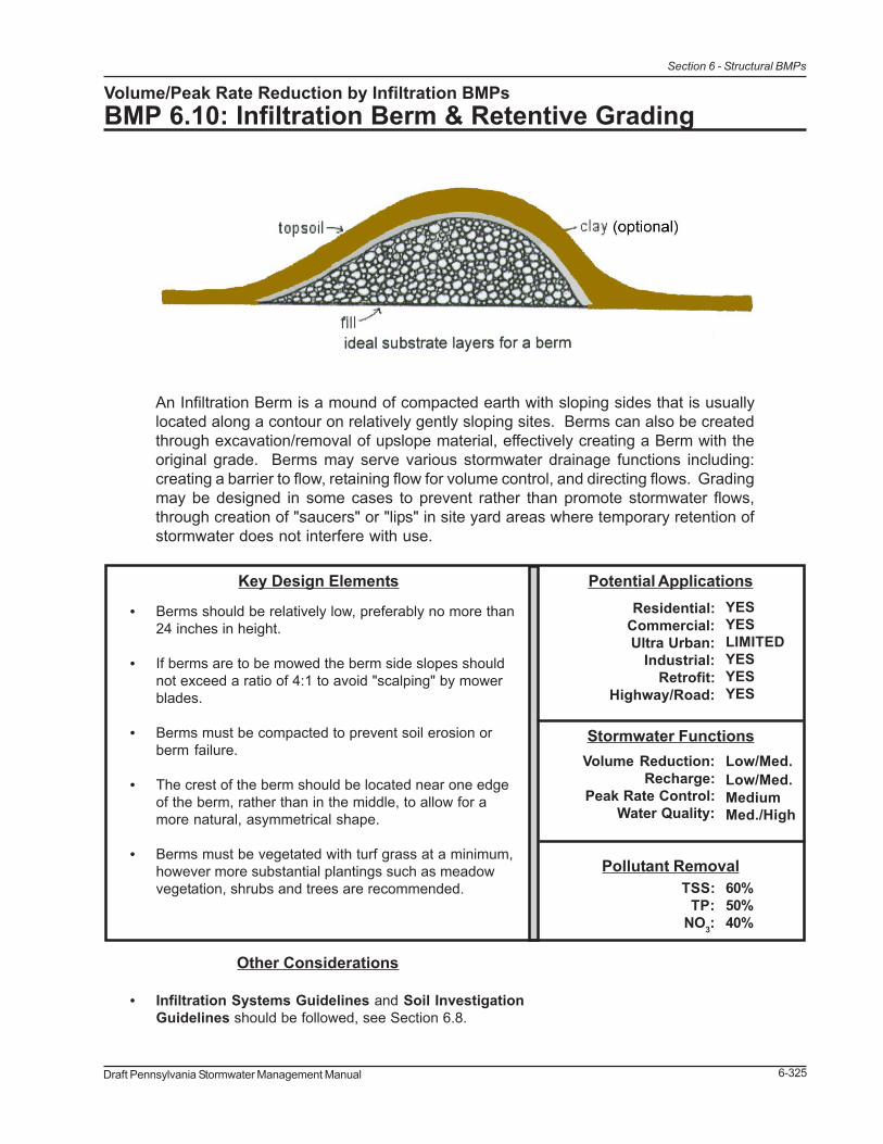
Draft Pennsylvania Stormwater Management Manual 6-325
Section 6 - Structural BMPs
Volume/Peak Rate Reduction by Infiltration BMPsBMP 6.10: Infiltration Berm & Retentive Grading
An Infiltration Berm is a mound of compacted earth with sloping sides that is usuallylocated along a contour on relatively gently sloping sites. Berms can also be createdthrough excavation/removal of upslope material, effectively creating a Berm with theoriginal grade. Berms may serve various stormwater drainage functions including:creating a barrier to flow, retaining flow for volume control, and directing flows. Gradingmay be designed in some cases to prevent rather than promote stormwater flows,through creation of "saucers" or "lips" in site yard areas where temporary retention ofstormwater does not interfere with use.
Other Considerations
• Infiltration Systems Guidelines and Soil InvestigationGuidelines should be followed, see Section 6.8.
Pollutant Removal60%50%40%
TSS:TP:
NO3:
Stormwater FunctionsLow/Med.Low/Med.MediumMed./High
Volume Reduction:Recharge:
Peak Rate Control:Water Quality:
Potential ApplicationsResidential:
Commercial:Ultra Urban:
Industrial:Retrofit:
Highway/Road:
YESYESLIMITEDYESYESYES
Key Design Elements
• Berms should be relatively low, preferably no more than24 inches in height.
• If berms are to be mowed the berm side slopes shouldnot exceed a ratio of 4:1 to avoid "scalping" by mowerblades.
• Berms must be compacted to prevent soil erosion orberm failure.
• The crest of the berm should be located near one edgeof the berm, rather than in the middle, to allow for amore natural, asymmetrical shape.
• Berms must be vegetated with turf grass at a minimum,however more substantial plantings such as meadowvegetation, shrubs and trees are recommended.

6-326 Draft Pennsylvania Stormwater Management Manual
Section 6 - Structural BMPs
Description
Infiltration Berms are linear landscape features located along (i.e. parallel to) existing site contours ina moderately sloping area. They can be described as built-up earthen embankments with slopingsides, which function to divert, retain, slow down, or divert stormwater flows. Berms are also utilizedfor reasons independent of stormwater management, such as to add interest to a flat landscape,create a noise or wind barrier, separate land uses, screen undesirable views or to enhance oremphasize landscape designs. Berms are often used in conjunction with recreational features, suchas pathways through woodlands. Therefore, when used for stormwater management, berms andother retentive grading techniques can serve multifunctional purposes and are easily incorporatedinto the landscape.
Infiltration Berms are shallow depressions created by berms that collect and temporarily storestormwater runoff allowing it to infiltrate into the ground and recharge groundwater. These are usuallyconstructed in series along a gradually sloping area.
1. Infiltration berms can be constructed on disturbed slopes and revegetated as part of theconstruction process.
2. They can be installed along the contours within an existing woodland area to slow andinfiltrate runoff from a development site.
3. May be constructed in combination with a subsurface infiltration trench at the base of theberm.
Infiltration Berms can provide runoff rate and volume control, though the level to which they do islimited by a variety of factors, including design variations (height, length, etc.), soil permeability rates,vegetative cover, and slope. Berms are ideal for mitigating runoff from relatively small imperviousareas with limited adjacent open space (e.g. roads, small parking lots). Systems of parallel bermshave been used to intercept stormwater from roadways or sloping terrain. Berms can be threadedcarefully in contours in wooded hillsides, minimally disturbing existing vegetation and yet still gainingstormwater management credit from the existing woodland used. Conversely, berms are oftenincapable of controlling runoff from very large, highly impervious sites. Due to their relatively limitedvolume capacity, the length and/or number of berms required to retain large quantities of runoff makethem impractical as the lone BMP in these cases. In these situations, berms are more appropriatelyused as pre- or additional-treatment for other more distributed infiltration systems closer to the sourceof runoff (i.e. porous pavement with subsurface infiltration).
Retentive grading may be employed in portions of sites where infiltration has been deemed to bepossible and where site uses are compatible. Ideally, such retentive grading will serve to createsubtle “saucers,” which contain and infiltrate stormwater flows. The “lip” of such saucers effectivelyfunction as a very subtle berm, which can be vertically impervious when vegetated and integratedinto the overall landscape.
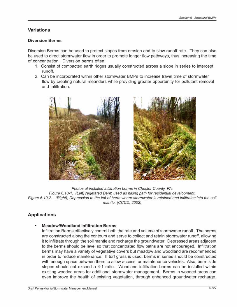
Draft Pennsylvania Stormwater Management Manual 6-327
Section 6 - Structural BMPs
Variations
Diversion Berms
Diversion Berms can be used to protect slopes from erosion and to slow runoff rate. They can alsobe used to direct stormwater flow in order to promote longer flow pathways, thus increasing the timeof concentration. Diversion berms often:
1. Consist of compacted earth ridges usually constructed across a slope in series to interceptrunoff.
2. Can be incorporated within other stormwater BMPs to increase travel time of stormwaterflow by creating natural meanders while providing greater opportunity for pollutant removaland infiltration.
Applications
• Meadow/Woodland Infiltration BermsInfiltration Berms effectively control both the rate and volume of stormwater runoff. The bermsare constructed along the contours and serve to collect and retain stormwater runoff, allowingit to infiltrate through the soil mantle and recharge the groundwater. Depressed areas adjacentto the berms should be level so that concentrated flow paths are not encouraged. Infiltrationberms may have a variety of vegetative covers but meadow and woodland are recommendedin order to reduce maintenance. If turf grass is used, berms in series should be constructedwith enough space between them to allow access for maintenance vehicles. Also, berm sideslopes should not exceed a 4:1 ratio. Woodland infiltration berms can be installed withinexisting wooded areas for additional stormwater management. Berms in wooded areas caneven improve the health of existing vegetation, through enhanced groundwater recharge.
Photos of installed infiltration berms in Chester County, PA.Figure 6.10-1. (Left)Vegetated Berm used as hiking path for residential development.
Figure 6.10-2. (Right), Depression to the left of berm where stormwater is retained and infiltrates into the soilmantle. (CCCD, 2002)

6-328 Draft Pennsylvania Stormwater Management Manual
Section 6 - Structural BMPs
Care shall be taken during construction to ensure minimum disturbance to existing vegetation,especially tree roots.
• Slope ProtectionDiversion Berms can be used to protect steeply sloping areas from erosion. Berms maydivert concentrated discharge from a developed area away from the sloped area. Additionally,berms may be installed in series down the slope to retain flow and spread it out along multiplelevel berms to discourage concentrated flow.
• Flow Pathway CreationBerms may be utilized to create or enhance stormwater flow pathways within existing orproposed BMPs, or as part of an LID strategy. Berms can be installed such that vegetatedstormwater flow pathways are allowed to “meander” so that stormwater travel time is increased.For example, berms can be utilized within existing BMPs as part of a retrofit strategy to eliminateshort-circuited inlet/outlet situations within detention basins. Flow pathway creation can beutilized as part of an LID strategy to disconnect roof leaders and attenuate runoff, whileincreasing pervious flow pathways within developed areas. Berms should be designed tocompliment the landscape while diverting runoff across vegetated areas and allowing forlonger travel times to encourage pollutant removal and infiltration.
• Constructed Wetland BermsBerms are often utilized within constructed wetland systems in order to create elongated flowpathways with a variety of water depths. See BMP 6.13 – Constructed Wetlands.
Design Considerations
1. Sizing criteria are dependent on berm function, location and storage volume requirements.a. Low berm height (less than or equal to 24 inches) is recommended to encourage
maximum infiltration and to prevent excessive ponding behind the berm. Greater
Figure 6.10-3. Woodland Infiltration Berms
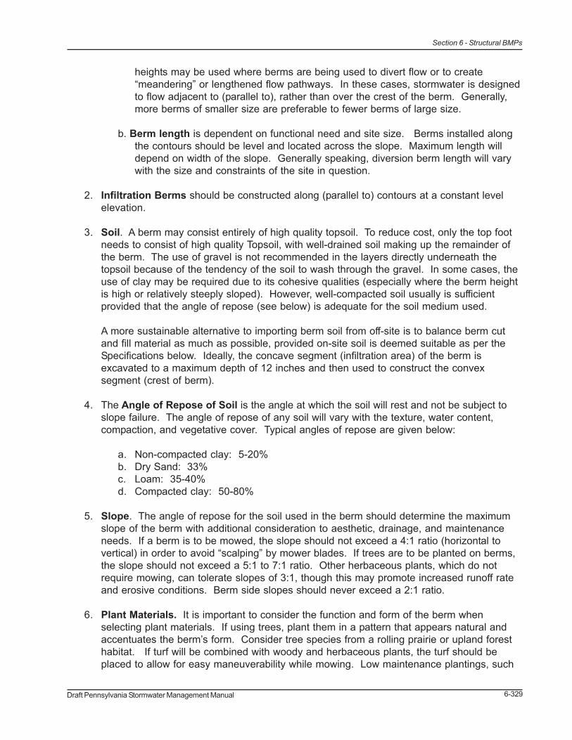
Draft Pennsylvania Stormwater Management Manual 6-329
Section 6 - Structural BMPs
heights may be used where berms are being used to divert flow or to create“meandering” or lengthened flow pathways. In these cases, stormwater is designedto flow adjacent to (parallel to), rather than over the crest of the berm. Generally,more berms of smaller size are preferable to fewer berms of large size.
b. Berm length is dependent on functional need and site size. Berms installed alongthe contours should be level and located across the slope. Maximum length willdepend on width of the slope. Generally speaking, diversion berm length will varywith the size and constraints of the site in question.
2. Infiltration Berms should be constructed along (parallel to) contours at a constant levelelevation.
3. Soil. A berm may consist entirely of high quality topsoil. To reduce cost, only the top footneeds to consist of high quality Topsoil, with well-drained soil making up the remainder ofthe berm. The use of gravel is not recommended in the layers directly underneath thetopsoil because of the tendency of the soil to wash through the gravel. In some cases, theuse of clay may be required due to its cohesive qualities (especially where the berm heightis high or relatively steeply sloped). However, well-compacted soil usually is sufficientprovided that the angle of repose (see below) is adequate for the soil medium used.
A more sustainable alternative to importing berm soil from off-site is to balance berm cutand fill material as much as possible, provided on-site soil is deemed suitable as per theSpecifications below. Ideally, the concave segment (infiltration area) of the berm isexcavated to a maximum depth of 12 inches and then used to construct the convexsegment (crest of berm).
4. The Angle of Repose of Soil is the angle at which the soil will rest and not be subject toslope failure. The angle of repose of any soil will vary with the texture, water content,compaction, and vegetative cover. Typical angles of repose are given below:
a. Non-compacted clay: 5-20%b. Dry Sand: 33%c. Loam: 35-40%d. Compacted clay: 50-80%
5. Slope. The angle of repose for the soil used in the berm should determine the maximumslope of the berm with additional consideration to aesthetic, drainage, and maintenanceneeds. If a berm is to be mowed, the slope should not exceed a 4:1 ratio (horizontal tovertical) in order to avoid “scalping” by mower blades. If trees are to be planted on berms,the slope should not exceed a 5:1 to 7:1 ratio. Other herbaceous plants, which do notrequire mowing, can tolerate slopes of 3:1, though this may promote increased runoff rateand erosive conditions. Berm side slopes should never exceed a 2:1 ratio.
6. Plant Materials. It is important to consider the function and form of the berm whenselecting plant materials. If using trees, plant them in a pattern that appears natural andaccentuates the berm’s form. Consider tree species from a rolling prairie or upland foresthabitat. If turf will be combined with woody and herbaceous plants, the turf should beplaced to allow for easy maneuverability while mowing. Low maintenance plantings, such
6-330 Draft Pennsylvania Stormwater Management Manual
Section 6 - Structural BMPs
as trees and meadow plants, rather than turf and formal landscaping, are encouraged.
7. Infiltration Design. Infiltration berms located along slopes should be composed of lowberms (less than 12 inches high) and should be vegetated. Subsurface soils should beuncompacted to encourage infiltration behind the berms. Soil testing is not required whereberms are located within an existing woodland, but soil maps/data should be consultedwhen siting the berms. Where feasible, surface soil testing should be conducted in orderto estimate potential infiltration rates.
8. Infiltration Trench Option. Soil testing is required for infiltration berms that will utilize asubsurface infiltration trench. Infiltration trenches are not recommended in existingwoodland areas as excavation and installation of subsurface trenches could damage treeroot systems. See BMP 6.4 – Infiltration Trench, for information on infiltration trenchdesign.
9. Aesthetics. To the extent possible, berms should reflect the surrounding landscape.Berms should be graded so that the top of the berm is smoothly convex and the toes of theberms are smoothly concave. Natural, asymmetrical berms are usually more effective andattractive than symmetrical berms. The crest of the berm should be located near one endof the berm rather than in the middle.
Figure 6.10-4. Asymmetrical Berm
Draft Pennsylvania Stormwater Management Manual 6-331
Section 6 - Structural BMPs
Detailed Stormwater Functions
Infiltration Area
The Infiltration Area is the ponding area behind the berm, defined as:Length of ponding x Width ponding area = Infiltration Area (Ponding Area)
If an infiltration trench is utilized behind the berm, infiltration area is defined as follows:Length of trench x Width of trench = Infiltration Area (Area of trench)
Volume Reduction Calculations
Storage volume can be calculated for Infiltration Berms. The storage volume is defined as the pondingarea created behind the berm, beneath the discharge invert (i.e. the crest of the berm). Storagevolume can be calculated differently depending on the variations utilized in the design.
Surface Storage Volume is defined as the volume of water stored on the surface at the pondingdepth. This is equal to:Cross-sectional area x Berm length = Surface Storage Volume
Subsurface Storage Volume is defined as the volume of water stored within a subsurface storage/infiltration trench (if this variation is utilized). The subsurface storage volume is calculated in additionto the surface storage volume and is used when additional storage volume is necessary to meetvolume/rate requirements.
This is equal to:Length x Width x Depth below invert x Void Ratio in Stone = Subsurface Storage Volume
The void ratio in stone is 40% for AASHTO No 3. If the conveyance pipe or a perforated distributionpipe is within the Storage Volume area, the volume of the pipe may also be included. All Infiltrationbeds should be designed to infiltrate or empty within 48 hours.
Peak Rate Mitigation:
See Section 9 for Peak Rate Mitigation methodology which addresses link between volume reductionand peak rate control.
Water Quality Improvement:
See Section 9 for Water Quality Improvement methodology which addresses pollutant removaleffectiveness of this BMP.
Construction Sequence
The following is a typical construction sequence for a infiltration berm without a subsurface infiltrationtrench, though alterations will be necessary depending on design variations.

6-332 Draft Pennsylvania Stormwater Management Manual
Section 6 - Structural BMPs
1. Install temporary sediment and erosion control BMPs as per the Pennsylvania Erosion andSediment Pollution Control Program Manual.
2. Complete site grading and stabilize within the limit of disturbance except where InfiltrationBerms will be constructed; make every effort to minimize berm footprint and necessaryzone of disturbance (including both removal of exiting vegetation and disturbance of emptysoil) in order to maximize infiltration.
3. Lightly scarify the soil in the area of the proposed berm before delivering soil to site.
4. Bring in fill material to make up the major portion of the berm. Soil should be added in 8-inch lifts and compacted after each addition according to design specifications. The slopeand shape of the berm should graded out as soil is added.
5. Protect the surface ponding area at the base of the berm from compaction. If compactionof this area does occur, scarify soil to a depth of at least 8 inches.
6. Complete final grading of the berm after the top layer of soil is added. Tamp soil downlightly and smooth sides of the berm. The crest and base of the berm should be levelalong the contour.
7. Plant berm with turf, meadow plants, shrubs or trees, as desired.
8. Mulch planted and disturbed areas with compost mulch to prevent erosion while plantsbecome established.
Maintenance Issues
Infiltration Berms have low to moderate maintenance requirements, depending on the design.
Infiltration Berms• Regularly inspect to ensure they are infiltrating; monitor drawdown time after major
storm events• Inspect any structural components, such as inlet structures to ensure proper
functionality• If planted in turf grass, maintain by mowing. Other vegetation will require less
maintenance. Trees and shrubs may require annual mulching, while meadowplanting requires annual mowing and clippings removal.
• Avoid running heavy equipment over the infiltration area at the base of the berms.The crest of the berm may be used as access for heavy equipment when necessaryto limit disturbance.
• Do not apply pesticides or fertilizers in and around infiltration structures.• Routinely remove accumulated trash and debris.• Remove invasive plants as needed• Inspect for signs of flow channelization; restore level spreading immediately after
deficiencies are observed
Diversion Berms• Regularly inspect for erosion or other failures.
Draft Pennsylvania Stormwater Management Manual 6-333
Section 6 - Structural BMPs
• Regularly inspect structural components to ensure functionality.• Maintain turf grass and other vegetation by mowing and re-mulching.• Do not apply pesticides or fertilizers where stormwater will be conveyed.• Remove invasive plants as needed.• Routinely remove accumulated trash and debris.
Cost Issues
Generally speaking, construction and maintenance costs are comparable to that of large stormwaterbasins. Because berms can be incorporated into the landscape and can provide aesthetic valuesome of their cost can be offset. Woodland infiltration berms can be less expensive than other BMPoptions because clearing and grubbing of existing woodlands is not necessary for installation ofother stormwater management features. Cost will depend on height and width of berms as well asdesired vegetation.
Specifications
The following specifications are provided for information purposes only. These specifications includeinformation on acceptable materials for typical applications, but are by no means exclusive or limiting.The designer is responsible for developing detailed specifications for individual design projects inaccordance with the project conditions.
1. Soil Materialsa. Satisfactory soil materials are defined as those complying with ASTM D2487 soil
classification groups GW, GP, GM, SM, SW, and SP.b. Unsatisfactory soil materials are defined as those complying with ASTM D2487 soil
classification groups GC, SC, ML, MH, CL, CH, OL, OH, and PT.c. Topsoil: Topsoil stripped and stockpiled on the site should be used for fine grading.
Topsoil is defined as the top layer of earth on the site, which produces heavygrowths of crops, grass or other vegetation.
d. Soils excavated from on-site may be used for berm construction provided they aredeemed satisfactory as per the above recommendations or by a soil scientist.
2. Placing and Compacting of Berm Area Soila. Ground Surface Preparation: Remove vegetation, debris, unsatisfactory soil
materials, obstructions, and deleterious materials from ground surface prior toplacement of fill. Plow strip, or break up sloped surfaces steeper than I vertical to 4horizontal so that fill material will bond with existing surface.
b. When existing ground surface has a density less than that specified under g.(below) for particular area classification, break up ground surface, pulverize, bringthe moisture-condition to optimum moisture content, and compact to required depthand percentage of maximum density.
c. Place backfill and fill materials in layers not more than 8 inches in loose depth formaterial to be compacted by heavy compaction equipment, and not more than 4inches in loose depth for material to be compacted by hand-operated tampers.
d. Before compaction, moisten or aerate each layer as necessary to provide optimummoisture content. Compact each layer to required percentage of maximum drydensity or relative dry density for each area classification. Do not place backfill or fillmaterial on surfaces that are muddy, frozen, or contain frost or ice.

6-334 Draft Pennsylvania Stormwater Management Manual
Section 6 - Structural BMPs
e. Place backfill and fill materials evenly adjacent to structures, piping, or conduit torequired elevations. Prevent wedging action of backfill against structures ordisplacement of piping or same elevation in each lift.
f. Control soil and fill compaction, providing minimum percentage of density specifiedfor each area classification indicated below. Correct improperly compacted areas orlifts if soil density tests indicate inadequate compaction.
g. Percentage of Maximum Density Requirements: Compact soil to not less than thefollowing percentages of maximum density, in accordance with ASTM D 1557:• Under lawn or unpaved areas, compact top 6 inches of subgrade and eachlayer of backfill or fill material at 85 percent maximum density.• Under infiltration areas no compaction shall be permitted.
3. Gradinga. General: Uniformly grade areas within limits of grading under this section, including
adjacent transition areas. Smooth finished surface within specified tolerances;compact with uniform levels or slopes between points where elevations areindicated or between such points and existing grades.
b. Lawn or Unpaved Areas: Finish areas to receive topsoil to within not more than 0.10foot above or below required subgrade elevations.
c. Compaction: After grading, compact subgrade surfaces to the depth and indicatedpercentage of maximum or relative density for each area classification.
4. Temporary Seedinga. Temporary seeding and mulching shall be required on all freshly graded areas
immediately following earth moving procedures. Seed-free straw or salt hay mulchshall be applied at a rate of 75 lbs. per 1,000 square feet over temporary seededareas. Straw bale barriers shall be placed in swale areas until vegetation isestablished.
b. Should temporary seeding not be possible or not establish itself properly, mulch asdescribed above, pending fine grading or permanent seeding.
5. Finish Gradinga. Spreading of topsoil and finish grading shall be coordinated with the work of the
Landscape Contractor.b. Verify that the rough grades meet requirements for tolerances, materials, and
compaction.c. Surface of subgrades shall be loosened and made friable by cross-discing or
harrowing to a depth of 2 inches. Stones and debris more than 1-1.5 inches in anydimension shall be raked up and grade stakes and rubbish removed.
d. Topsoil shall be uniformly spread to minimum depths after settlement of 6 inches onareas to be seeded and 4 inches on areas to be sodded. Correct any surfaceirregularities to prevent formation of low spots and pockets that would retain water.
e. Topsoil shall not be placed when the subgrade is frozen, excessively wet, orextremely dry and no topsoil shall be handled when in a frozen or muddy condition.During all operations following topsoil spreading, the surface shall be kept free fromstones over 1-1.5 inches in size or any rubbish, debris, or other foreign material.
f. After placing topsoil rake soil to a smooth, even-draining surface and compact lightlywith an empty water roller. Leave finish graded areas clean and well raked, readyfor lawn work.

Draft Pennsylvania Stormwater Management Manual 6-335
Section 6 - Structural BMPs
References
AMEC Earth and Environmental Center for Watershed Protection et al. Georgia StormwaterManagement Manual. 2001.
Harris, C. and Dines, N. Time Saver Standards for Landscape Architecture, 2nd Edition. New York,NY: McGraw-Hill, 1998.
University of Minnesota. “Building Soil Berms.” Sustainable Urban Landscape Information Series(SULIS). 1998. <http://www.sustland.umn.edu/implement/soil_berms.html>
Chester County Conservation District. Chester County Stormwater BMP Tour Guide-InfiltrationTrenches (Infiltration Berms). 2002.
Williams, G.P. Canadian Building Digest - Drainage and Erosion at Construction Sites. NationalResearch Council Canada. 2004. <http://irc.nrc-cnrc.gc.ca/cbd/cbd183e.html>

6-336 Draft Pennsylvania Stormwater Management Manual
Section 6 - Structural BMPs

Draft Pennsylvania Stormwater Management Manual 6-337
Section 6 - Structural BMPs
6.5 Volume/Peak Rate Reduction BMPs

6-338 Draft Pennsylvania Stormwater Management Manual
Section 6 - Structural BMPs

Draft Pennsylvania Stormwater Management Manual 6-337
Section 6 - Structural BMPs
6.5 Volume/Peak Rate Reduction BMPs

6-338 Draft Pennsylvania Stormwater Management Manual
Section 6 - Structural BMPs

Draft Pennsylvania Stormwater Management Manual 6-339
Section 6 - Structural BMPs
Volume/Peak Rate Reduction BMPsBMP 6.11: Vegetated Roof
An extensive vegetated roof cover is a veneer ofvegetation that is grown on and completely covers anotherwise conventional flat or pitched roof, endowingthe roof (>30o slope) with hydrologic characteristicsthat more closely match surface vegetation than theroof. The overall thickness of the veneer may rangefrom 2 to 6 inches and may contain multiple layers,consisting of waterproofing, synthetic insulation, non-soil engineered growth media, fabrics, and syntheticcomponents. Vegetated roof covers can be optimizedto achieve water quantity and water quality benefits.Through the appropriate selection of materials, eventhin vegetated covers can provide significant rainfallretention and detention functions.
Pollutant Removal85%85%30%
TSS:TP:
NO3:
Stormwater FunctionsMed/V. HighMediumMed/V. HighLow to High
Volume Reduction:Recharge:
Peak Rate Control:Water Quality:
Potential ApplicationsResidential:
Commercial:Ultra Urban:
Industrial:Retrofit:
Highway/Road:
YESYESYESYESYESNO
Key Design Elements• 2-6 inches of non-soil engineered media; assem-
blies that are 4 inches and deeper may includemore than one type of engineered media
• Engineered media should have a high mineralcontent. Engineered media for extensive veg-etated roof covers is typically 85% to 97% non-organic (wet combustion or loss on ignition meth-ods).
• Vegetated roof covers intended to achieve waterquality benefits should not be fertilized
• Irrigation is not a desirable component of veg-etated covers used as best management practices
• Internal building drainage, including provisions tocover and protect deck drains or scuppers, mustanticipate the need to manage large rainfall eventswithout inundating the cover.
• Assemblies planned for roofs with pitches steeperthan 2:12 must incorporate supplemental mea-sures to insure stability against sliding.
Other Considerations• The roof structure must be evaluated for compatibility with the maximum predicted dead and live
loads. Typical dead loads for wet extensive vegetated covers range from 8 to 36 pounds per squarefoot. Live load is a function of rainfall retention. For example, 2 inches of rain equals 10.4 lbs. persquare foot of live load.. It requires 20 inches of snow to have the same live load per square foot.
• The waterproofing must be resistant to biological and root attack. In many instances a supplementalroot-fast layer is installed to protect the primary waterproofing membrane from plant roots.
• Standards and guidelines (in English) for the design of green roofs are available from FLL1, aEuropean non-profit trade organization. In the United States, new standards and guidelines are indevelopment by ASTM (American Standard Testing Methods).
1 Guidelines for the Planning, Installation, and Maintenance in Roof Greening, 1995, English Version (Richtlinen für die Planung, Ausführungund Pflege von Dachbegrünungen), Forschungsgesellschaft Landschaftsentwicklung Landschaftsbau e.V.

6-340 Draft Pennsylvania Stormwater Management Manual
Section 6 - Structural BMPs
Description
Extensive vegetated roof covers are 6 inches, or less, in depth and are typically intended to achievea specific environmental benefit, such as rainfall runoff mitigation. For this reason they are mostcommonly un-irrigated. While some installations are open to public access, most extensive vegetatedroof covers are for viewing only. In order to make them practical for installation on conventional roofstructures, lightweight materials are used in the preparation of most engineered media. Developmentsin the last 40 years that have made these systems viable include: 1) recognition of the value ofvegetated covers in restoring near open-space hydrologic performance on impervious surfaces, 2)advances in waterproofing materials and methods, and 3) development of a reliable temperate climateplant list that can thrive under the extreme growing conditions on a roof.
Vegetated roof covers that are 10 inches, or deeper, are referred to as ‘intensive’ vegetated roofcovers. These are more familiar in the United States and include many urban landscaped plazas.Intensive assemblies can also provide substantial environmental benefits, but are intended primarilyto achieve aesthetic and architectural objectives. These types of systems are considered “roof gardens”and are not to be confused with the simple “extensive” design.
Variations
Most extensive vegetated roof covers fall into three categories
• Single media with synthetic under-drain layer• Dual media• Dual media with synthetic retention/detention layer
All vegetated roof covers will require a premium waterproofing system. Depending on the waterproofingmaterials selected, a supplemental root-fast layer may be required to protect the primary waterproofingmembrane from plant roots.
Figure 6.11-1. Cross-section diagram showing layers in vegetated roof system (Roofscapes, Inc.)

Draft Pennsylvania Stormwater Management Manual 6-341
Section 6 - Structural BMPs
Insulation, if included in the roof covering system, may be installed either above or below the primarywaterproofing membrane. Most vegetated roof cover system can be adapted to either roofingconfiguration. In the descriptions that follow, the assemblies refer to the conventional configuration,in which the insulation layer is below the primary waterproofing.
All three extensive roof cover variations can be installed without irrigation. Un-irrigated assembliesare strongly recommended. While this may place some limits on the type of plants that can be grown,the benefits are that assembly will perform better as a stormwater BMP, and the maintenancerequirements will be substantially reduced.
Some assemblies are installed in tray-like modules to facilitate installation, especially in confinedlocations.
Single media assembliesSingle media assemblies are commonly used for pitched roof applications and for thin and lightweightinstallations. These systems typically incorporate very drought tolerant plants and utilize coarseengineered media with high permeability. A typical profile would include the following layers.
• Waterproofing membrane• Root-barrier (optional, depending on the root-fastness of the waterproofing)• Semi-rigid plastic geocomposite drain or mat (typical mats are made from non-
biodegradable fabric or plastic foam)• Separation geotextile• Engineered growth media• Foliage layer
Pitched roof applications may require the addition of slope bars, rigid slope stabilization panels,cribbing, reinforcing mesh, or similar method of preventing sliding instability.
Flat roof applications with mats as foundations typically require a network of perforated internaldrainage conduit to enhance drainage of percolated rainfall to the deck drains or scuppers.
Assemblies with mats can be irrigated from beneath, while assemblies with drainage compositesrequire direct drainage.
Dual media assembliesDual media assemblies utilize two types of non-soil media. In this case a finer-grained media withsome organic content is placed over a basal layer of coarse lightweight mineral aggregate. They donot include a geocomposite drain. The objective is to improve drought resistance by replicating anatural growing environment in which sandy topsoil overlies gravelly subsoil. These assemblies aretypically 4 to 6 inches thick and include the following layers:
• Waterproofing membrane• Protection layer• Coarse-grained drainage media• Root-permeable nonwoven separation geotextile• Fine-grained engineered growth media layer• Foliage layer

6-342 Draft Pennsylvania Stormwater Management Manual
Section 6 - Structural BMPs
These assemblies are suitable for roofs with pitches less than, or equal to, 1.5:12. Large vegetatedcovers will generally incorporate a network of perforated internal drainage conduit.
Dual media systems are ideal for in combination with base irrigation methods.
Dual media with synthetic retention/detention layerThese assemblies introduce plastic panels with cup-like receptacles on their upper surface (i.e., amodified geocomposite drain sheet). The panels are in-filled with coarse lightweight mineral aggregate.The cups trap and retain water. They also introduce an air layer at the bottom of the assembly. Atypical profile would include:
• Waterproofing membrane• Felt fabric• Retention/detention panel• Coarse-grained drainage media• Separation geotextile• Fine grained ‘growth’ media layer
• Foliage layer
These assemblies are suitable on roof with pitches less than or equal to 1:12. Due to their complexity,these system are usually 5 inches or deeper.
If required, irrigation can be provided via surface spray or mid-level drip.
• Stormwater Volume and Rate ControlVegetated roof covers are an “at source” measure for reducing the rate and volume ofrunoff released during rainfall events. The water retention and detention properties ofvegetated roof covers can be enhanced through selection of the engineered media andplants.
Figure 6.11-2. Stabilization of media during initial planting

Draft Pennsylvania Stormwater Management Manual 6-343
Section 6 - Structural BMPs
• Runoff Water Quality ImprovementsDirect runoff from roofs is a contributor to NPS pollutant releases. Vegetated roof coverscan significantly reduce this source of pollution. Assemblies intended to produce waterquality benefits will employ engineered media with 100% mineral content. Furthermore,following the plant establishment period (usually about 18 months), on-going fertilizationof the cover should not be permitted. Experience indicates that it will take five or moreyears for a water quality vegetated cover to attain its potential pollutant removal efficiency.
• In Combination with Infiltration MeasuresVegetated roof covers are frequently combined with ground infiltration measures. Vegetatedroof covers improve the efficiency of infiltration devices by:
• Reducing the peak runoff rate• Prolonging the runoff• Filtering runoff to produce a clear effluent
Roofs that are designed to achieve water quality improvements will also reduce pollutantinputs to infiltration devices.
• Habitat Restoration/CreationVegetated roof covers have been used to create functional meadows and wetlands tomitigate the development of open space. This can be accomplished with assemblies asthin as 6 inches.
Design Considerations
1. Live and dead load bearing capacity of the roof must be established. Dead loads shouldbe estimated using media weights determined using a standardized laboratory procedure.1
2. Waterproofing materials must be durable under the conditions associated with vegetatedcovers. A supplemental root-barrier layer should be installed in conjunction with materialsthat are not root-fast.
3. Roof flashings should extend 6 inches higher than the top of the growth media surface andbe protected by counter-flashings.
4. The design should incorporate measures to protect the waterproofing membrane fromphysical damage during and after installation of the vegetated cover assembly.
5. Vegetated roof covers should incorporate internal drainage capacity sufficient to accommo-date a two-year return frequency rainfall without generating surface runoff flow.
6. Deck drains, scuppers, or gravel stops serving as methods to discharge water from the roofarea should be protected with an access chambers. These enclosures should includeremovable lids in order to allow ready access for inspection.

6-344 Draft Pennsylvania Stormwater Management Manual
Section 6 - Structural BMPs
7. The physical properties of the engineered media should be selected appropriately in orderto achieve the desired hydrologic performance.
8. Engineered media should contain no clay size particles and should contain no more than15% organic matter (wet combustion or loss on ignition methods)
9. Media used in constructing vegetated roof covers should have a maximum moisture capac-ity2 of between 30% and 40%.
Figure 6.11-4. A vegetated roof
Figure 6.11-3. Ponding of water on a standard rooftop

Draft Pennsylvania Stormwater Management Manual 6-345
Section 6 - Structural BMPs
10.Plants should be selected which will create a vigorous, drought-tolerant ground cover. InPennsylvania the most successful and commonly used ground covers for un-irrigatedprojects are varieties of Sedum and Delosperma. In the Pennsylvania climate Delospermais deciduous. Both deciduous and evergreen varieties of Sedum are available. Deeperassemblies (i.e., 4 to 6 inches) can also incorporate a wider range of plants includingDianthus, Phlox, Antennaria, and Carex.
11.Roofs with pitches exceeding 2:12 will require supplemental measures to insure stabilityagainst sliding
Detailed Stormwater Functions
The performance of vegetated roof covers as stormwater best management practices cannot berepresented by a simple algebraic expression. Conventional methods are used to estimate surfacerunoff from various types of surfaces. In the analysis of vegetated roof covers, the water that isdischarged from the roof is not surface runoff, but rather underflow, i.e., or percolated water. Therate and quantity of water released during a particular design storm can be predicted based onknowledge of key physical properties, including:
• Maximum media water retention• Field capacity• Plant cover type• Saturated hydraulic conductivity• Non-capillary porosity
The maximum media water retention is the maximum quantity of water that can be held againstgravity under drained conditions. Standards that have been developed specifically for measuringthis quantity in roof media are available from FLL and ASTM (draft).
Conventional runoff coefficients, such as the NRCS runoff curve number, CN or the rational methodrunoff coefficient, C, can be back-calculated from computer simulation of vegetated roof coverassemblies. However, these coefficients will only apply for the specific design storm for which theyhave been determined.
Peak Rate Mitigation
Vegetated roof covers can exert a large influence on runoff peak rates derived from roofs. An evaluationof peak runoff rates requires either computer simulation or measurements made using prototypeassemblies.
A general rule for vegetated roof covers is that rate of runoff from the covered roof surface will be lessthan or equal to that of open space (i.e., NRCS curve number of 65) for storm events with total rainfallvolumes equal to 3 times the maximum media water retention of the assembly. For example, arepresentative vegetated roof cover with a maximum moisture retention of 1 inch will react like openspace for storms up to and including the 3-inch magnitude storm.
Using the German RWS program, the designer could generate a table of C or CN values for specificdesign storms. The table would relate maximum moisture capacity to the C and/or CN coefficients.For the table to be used, a vegetated cover would have to comply with European guidelines.

6-346 Draft Pennsylvania Stormwater Management Manual
Section 6 - Structural BMPs
Volume Reduction Calculations
All vegetated roof covers have both a retention and a detention volume component. Benchmarks forthese volumes can be developed from the physical properties described above (Detailed StormwaterFunctions).
The interaction of retention and detention produce both short-term effects (i.e., control of singlestorms) and long-term effects (i.e., reductions in total seasonal or annual roof runoff). Continuoussimulation using a representative annual rainfall record from a local weather station is required inorder to predict the long-term runoff versus rainfall benefit. The effectiveness of vegetated roofcovers will vary according to the regional pattern of rainfall.
Using the German RWS program, the designer could generate a table of volume reductions forseveral regions in Pennsylvania. The table would relate the runoff ratio (runoff/rainfall) based on oneor two types of cover assemblies and selected regions in PA for which good weather data is available.For the table to be used, a vegetated cover would have to comply with European guidelines.
Water Quality Improvement
Once the plant cover is established, nutrient additions should be suspended. Experience indicatesthat the efficiency of vegetated covers in reducing pollutant and nutrient releases from roofs willincrease with time. The vegetated cover should reach its optimum performance after about fiveyears.
See in Section 9 for Water Quality Improvement methodology that addresses pollutants removaleffectiveness of this BMP.
Figure 6.11-5. 350-year old vegetated roof system in Stockhom, Sweden

Draft Pennsylvania Stormwater Management Manual 6-347
Section 6 - Structural BMPs
Construction Sequence
1. Visually inspect the completed waterproofing to identify any apparent flaws, irregularities,or conditions that will be interfere with the security or functionality of the vegetated coverssystem. The waterproofing should be tested for watertightness by the roofing applicator.
2. Institute a protection program
3. Introduce measures to protect the finished waterproofing from physical damage
4. Install slope stabilization measures (pitched roofs with pitches in excess of 2:12) *
5. If the waterproofing materials are not root fast, install a root-barrier layer
6. Layout key drainage and irrigation components, including drain access chambers, internaldrainage conduit, confinement border units, and isolation frames (for root-top utilities,hatches and penetrations)
7. Install walkways and paths (projects with public access)
8. Test irrigation systems (as relevant for roof gardens)
9. Install the drainage layer. Depending on the variation type, this could be a geocompositedrain, mat, or course of drainage media.
10. Cover the drainage layer with the separation fabric (in some assemblies, the separationfabric is pre-bonded to a synthetic drainage layer.
11. Install the upper growth media layer (dual media assemblies only)
Figure 6.11-6. Cross section showing edge detail courtesy of Roofscapes, Inc.

6-348 Draft Pennsylvania Stormwater Management Manual
Section 6 - Structural BMPs
12.Establish the foliage cover plantings from cuttings, seed, plugs or pre-grown mats
13.Provide protection from wind disruptions as warranted by the project conditions, and plantestablishment method.
* In some installations slope stabilizing measures can be introduced as part of the roof structureand will be already be in-place at the start of the construction sequence.
Maintenance Issues
• During the plant establishment period, periodic irrigation may be required
• During the plant establishment period, three to four visits to conduct basic weeding,fertilization, and in-fill planting is recommended. Thereafter, only two annual visits forinspection and light weeding should be required (irrigated assemblies will require moreintensive maintenance).
Cost Issues
The construction cost of vegetated roof covers can vary greatly, depending on factors such as:
• Height of the building• Accessibility to the structure by large equipment such as cranes and trailers• Depth and complexity of the assembly• Remoteness of the project from sources of material supply• Size of the project
Figure 6.11-7. Parapet detail courtesy of Roofscapes, Inc.

Draft Pennsylvania Stormwater Management Manual 6-349
Section 6 - Structural BMPs
However, under present market conditions (2004), extensive vegetated covers for roof will typicallyrange between $8 and $15 per square foot, including design, installation, and warranty service.Basic maintenance for extensive vegetated covers typically requires about 3 man-hours per 1,000square feet, annually.Specifications
The following specifications are provided for information purposes only. These specifications includeinformation on acceptable materials for typical applications, but are by no means exclusive or limiting.The designer is responsible for developing detailed specifications for individual design projects inaccordance with the project conditions.
Due to the very large variation in assembly types and methods, it is not possible to provide acomprehensive specification. Performance specifications, describing the assembly elements andtheir physical properties can be obtained from commercial providers of vegetated roof covers. Thereferences provided also offer specific guidance for the selection of materials and methods.
Some key components and associated performance-related properties are as follows:
1. Root-barriers should be thermoplastic membranes with a thickness of at least 30 mils.Thermoplastic sheets can be bonded using hot-air fusion methods, rendering the seamssafe from root penetration. Membranes that have been certified for use as root-barriersare recommended. At present only FLL offers a recognized test for root-barriers. SeveralFLL-certified materials are available in the United States. Interested Americanmanufactures can submit products for testing to FLL-certified labs.
2. Granular drainage media should be a non-carbonate mineral aggregate conforming tothe following specifications:
Saturated Hydraulic Conductivity2 ≥ 25 in/min
Total Organic Matter, by Wet Combustion (MSA) ≤ 1%
Abrasion Resistance (ASTM-C131-96) ≤ 25% loss
Soundness (ASTM-C88 or T103 or T103-91) ≤ 5% loss
Porosity (ASTM-C29) ≥ 25%
Alkalinity, CaCO3 equivalents (MSA) ≤ 1 %
Grain-Size Distribution (ASTM-C136)
Pct. Passing US#18 sieve ≤ 1%Pct. Passing ¼-inch sieve ≤ 30%Pct. Passing 3/8-inch sieve ≥ 80%
3. Growth media should be a soil-like mixture containing not more than 15% organic content(wet combustion or loss on ignition methods). The appropriate grain-size distribution isessential for achieving the proper moisture content, permeability, nutrient management,and non-capillary porosity, and ‘soil’ structure. The grain-size guidelines vary for singleand dual media vegetated cover assemblies.

6-350 Draft Pennsylvania Stormwater Management Manual
Section 6 - Structural BMPs
Non-capillary Pore Space at Field Capacity,0.333 bar (TMECC 03.01, A) ≥ 15% (vol)
Moisture Content at Field Capacity(TMECC 03.01, A) ≥ 12% (vol)
Maximum Media Water Retention (FLL) ≥ 30% (vol)Alkalinity, Ca CO3 equivalents (MSA) ≤ 2.5%Total Organic Matter by Wet Combustion (MSA) ≤ 3-15% (dry wt.)pH (RCSTP) 6.5-8.0Soluble Salts (DTPA saturated media ≤ 6 mmhos/cmextraction)”(RCSTP)Cation exchange capacity (MSA) ≥ 10 meq/100gSaturated Hydraulic Conductivity for Single
Media Assemblies (FLL)3 ≥ 0.05 in/minSaturated Hydraulic Conductivity for DualMedia Assemblies (FLL) ≥ 0.30 in/minGrain-size Distribution of the Mineral Fraction (ASTM-D422)
Single Media Assemblies
Clay fraction (2 micron) 0Pct. Passing US#200 sieve (i.e., silt fraction) ≤ 5%Pct. Passing US#60 sieve ≤ 10%Pct. Passing US#18 sieve 5 - 50%Pct. Passing 1/8-inch sieve 20 - 70%Pct. Passing 3/8-inch sieve 75 -100%
Dual Media Assemblies
Clay fraction (2 micron) 0Pct. Passing US#200 sieve (i.e., silt fraction) 5-15%Pct. Passing US#60 sieve 10-25%Pct. Passing US#18 sieve 20 - 50%Pct. Passing 1/8-inch sieve 55 - 95%Pct. Passing 3/8-inch sieve 90 -100%
Macro- and micro-nutrients shall be incorporated in the formulation in initial proportionssuitable for support the specified planting.
4. Separation fabric should be readily penetrated by roots, but provide a durable separationbetween the drainage and growth media layers (Only lightweight nonwoven geotextiles arerecommended for this function.
Unit Weight (ASTM-D3776) ≤ 4.25 oz/yd2
Grab tensile (ASTM-D4632) ≤ )90 lb
Mullen Burst Strength (ASTM-D4632) ≥ 135 lb/in
Permittivity (ASTM-D4491) ≥ 2 sec-1

Draft Pennsylvania Stormwater Management Manual 6-351
Section 6 - Structural BMPs
References
FLL: Guidelines for the Planning, Installation, and Maintenance in Roof Greening, 1995, EnglishVersion (Richtlinen für die Planung, Ausführung und Pflege von Dachbegrünungen),Forschungsgesellschaft Landschaftsentwicklung Landschaftsbau e.V.
ASTM: American Standard Testing Methods
Planting Green Roofs and Living Walls, 2004, Dunnett, N, and Kingsbury, N, Timber Press [ISBN 0-88192-640-X]
FOOTNOTES
1 FLL or ASTM procedures for determining the maximum density and associated moisture contentunder compressed and hydrated conditions. See ASTM Draft: Standard Test Method for MaximumMedia Density for Dead Load Analysis of Green Roof Systems , and ASTM Draft StandardPractice for Determination of Dead Loads and Live Loads f or Green Roof Systems
2 ASTM Draft: Standard Test Method for Saturated Hydraulic Conductivity of Granular DrainageMedia [Falling-Head Method] for Green Roof Systems

6-352 Draft Pennsylvania Stormwater Management Manual
Section 6 - Structural BMPs

Draft Pennsylvania Stormwater Management Manual 6-353
Section 6 - Structural BMPs
Volume/Peak Rate Reduction BMPsBMP 6.12: Rooftop Runoff - Capture & Reuse
Capture and Reuse encompasses a widevariety of water storage techniques designedto “capture” precipitation, hold it for a periodof time, and reuse the water. Heavy rainfallmay require slow release over time.
Pollutant RemovalTSS:
TP:NO3:
Stormwater FunctionsMed./HighLowLow*Medium
Volume Reduction:Recharge:
Peak Rate Control:Water Quality:
Potential ApplicationsResidential:
Commercial:Ultra Urban:
Industrial:Retrofit:
Highway/Road:
YesYESYESYESYESLIMITED
Key Design Elements
• Storage devices designed to capture a portion of thesmall, frequent storm events
• Storage techniques may include cisterns,underground tanks, above-ground vertical storagetanks, “rain barrels”, or other systems.
• Systems must provide for overflow or bypass of largestorm events
• Collection and placement of storage elements upgradient of areas of reuse may reduce or eliminatepumping needs
• Water must be used or discharged before next stormevent.
• Most effective when designed to meet a specificwater need for reuse.
* Depending on design scale
• Guidelines for Infiltration Systems apply if designedwith Infiltration
100%100%100%
Other Considerations

6-354 Draft Pennsylvania Stormwater Management Manual
Section 6 - Structural BMPs
Description
Cisterns, Rain Barrels, Vertical Storage, and similar devices have been used for centuries to capturestorm water from the roofs of buildings, and in many parts of the world these systems serve as aprimary water supply source. In the U.S., the reuse of stormwater for potable needs is not advisedwithout water treatment, although many homes in the U.S. were storing water in cisterns for reuse aslittle as a century ago. In the U.S. these systems can reduce potable water needs for uses such asirrigation and fire protection while also reducing stormwater discharges.
Storage/reuse techniques range from small, residential systems such as Rain Barrels that aremaintained by the homeowner to supplement garden needs, to large, “vertical storage” units thatcan provide fire needs. Storage/reuse techniques are useful in urban areas where there is littlephysical space to manage storm water.
Variations
Cisterns – large, underground or surface containers designed to hold large volumes of water (500gallons or more). Cisterns may be comprised of fiberglass, concrete, plastic, brick or other materials.
Rain barrels – barrel (or large container) that collect drainage from roof leaders and store water untilneeded for irrigation.
Figure 6.12-1. Cisterns are available from a variety of manufacturers, in a variety of sizes and materials.
Figure 6.12-2. Rain Barrels are available in a variety of materials and sizes

Draft Pennsylvania Stormwater Management Manual 6-355
Section 6 - Structural BMPs
Vertical Storage – stand along “towers”, or “fat downspouts” that usually rest against a buildingperforming the same capture, storage and release functions as cisterns and rain barrels.
Storage Beneath Structure – Storage may be incorporated into elements such as paths and walkwaysto supplement irrigation with the use of structural plastic storage units, such as RainStore or otherproducts.
Figure 6.12-3. Vertical storage units for vegetated roof plaza maintenance are common in Germany
Figure 6.12-5. RainStore
Figure 6.12-4. Cross-section detail showing storage of roof runoff beneath brick walkway using RainStoreunits.

6-356 Draft Pennsylvania Stormwater Management Manual
Section 6 - Structural BMPs
Applications
• Landscaped areas and gardens to meet irrigation needs• Storage for fire needs• Urban areas and Combined Sewer areas to reduce peak surcharges.• Reuse for greywater needs such as flushing toilets.• Reuse for athletic field irrigation
Figure 6.12-6. Cistern harvesting system for reuse to meet greywater needs (modified, fromwww.advancedbuildings.org/_frames/fr_t_plumbing_cisterns.htm)
Figure 6.12-7. Excavation of former residential water supply cistern in Ann Arbor, Michigan.

Draft Pennsylvania Stormwater Management Manual 6-357
Section 6 - Structural BMPs
Design Considerations
1. The Designer must calculate the water need for the intended uses. For example, whatwill the collected water be used for and when will it be needed? If a 2,000 square foot areaof lawn requires irrigation for 4 months in the summer at a rate of 1” per week, how muchwill be needed and how often will the storage unit be refilled? The usage requirements andthe expected rainfall volume and frequency must be determined.
2. Drawdown – the Designer must provide for use or release of the stored water betweenstorm events in order for the necessary stormwater storage volume to be available.
3. The Catchment Area on which the rain falls must be considered. The catchment areatypically handles roof runoff.
4. The Conveyance System must keep reused stormwater or greywater from other potablewater piping systems. Do not connect to domestic or commercial potable water system.
5. Pipes or storage units should be clearly marked “Caution: Reclaimed water, Do Not Drink”.
6. Screens may be used to filter debris from storage units.
7. The first flush runoff may be diverted away from storage in order to minimize sediment
Figure 6.12-8. Schematic cross-section showing roof runoff connected to underground cistern.

6-358 Draft Pennsylvania Stormwater Management Manual
Section 6 - Structural BMPs
and pollutant entry. However, rooftop runoff contains very low concentrations of NPSpollutants.
8. Storage elements should be protected from direct sunlight by positioning and landscaping.(Limit light into devices to minimize algae growth.)
9. The proximity to building foundations should be considered for overflow conditions.
10. Climate is an important consideration, and capture/reuse systems should be disconnectedduring winter to prevent freezing.
11. Cisterns should be watertight (joints sealed with nontoxic waterproof material) with asmooth interior surface, and capable of receiving water from rainwater harvesting system.
12. Covers (lids) should have a tight fit to keep out surface water, animals, dust and light.
13. Positive outlet for overflow should be provided a few inches from the top of the cistern.
14. Observation risers should be at least 6” above grade for buried cisterns.
15. Reuse may require pressurization. Water stored has a pressure of 0.43 psi per foot ofwater elevation. A ten-foot tank would have a head of 0.43*10 = 4.3 psi. Most irrigationsystems require at least 15 psi. To add pressure, a pump, pressure tank and fine meshfilter can be used, which adds to the cost of the system, but creates a more usable system.
Table 6.12-1. Annual Rainfall Yield (Gallons) for Impervious Surfaces (Square feet)
20 24 28 32 36 40 44 48 52sf
1000 11844 14213 16582 18951 21319 23688 26057 28426 307951100 13029 15634 18240 20846 23451 26057 28663 31268 338741200 14213 17056 19898 22741 25583 28426 31268 34111 369541300 15397 18477 21556 24636 27715 30795 33874 36954 400331400 16582 19898 23214 26531 29847 33164 36480 39796 431131500 17766 21319 24873 28426 31979 35532 39086 42639 461921600 18951 22741 26531 30321 34111 37901 41691 45481 492721700 20135 24162 28189 32216 36243 40270 44297 48324 523511800 21319 25583 29847 34111 38375 42639 46903 51167 554311900 22504 27005 31505 36006 40507 45008 49508 54009 585102000 23688 28426 33164 37901 42639 47377 52114 56852 615892100 24873 29847 34822 39796 44771 49745 54720 59694 646692200 26057 31268 36480 41691 46903 52114 57326 62537 677482300 27241 32690 38138 43586 49035 54483 59931 65380 708282400 28426 34111 39796 45481 51167 56852 62537 68222 739072500 29610 35532 41454 47377 53299 59221 65143 71065 769872600 30795 36954 43113 49272 55431 61589 67748 73907 800662700 31979 38375 44771 51167 57562 63958 70354 76750 831462800 33164 39796 46429 53062 59694 66327 72960 79593 86225
* Values represent 95% of actual precipitation to account for any storage and/or losses.
Rainfall (inches)Impervious Surface Area
Annual Rainfall Yield in Gallons for Various Impervious Surface Sizes and Rainfall Amounts

Draft Pennsylvania Stormwater Management Manual 6-359
Section 6 - Structural BMPs
Detailed Stormwater Functions
Volume Reduction Calculations
Volume reduction is actual volume of container, taking into consideration how many times it isemptied.
Peak Rate Mitigation Calculations:
Overall, capture and reuse takes a volume of water out of site runoff and puts it back into theground. This reduction in volume will translate to a lower overall peak rate for the site.
Water Quality Improvement
Pollutant removal takes place through filtration of recycled primary storage, and/or natural filtrationthrough soil and vegetation for overflow discharge. Quantifying pollutant removal will depend ondesign. Sedimentation will depend on area below outlet that is designed for sediment accumulation,time in storage, and maintenance frequency. Filtration through soil will depend on flow draining to anarea of soil, the type of soil (infiltration capacity), and design specifics (stone bed, etc.).
Construction Sequence
Install per manufacturer’s instructions.
Maintenance Issues
Flush cisterns to remove sediment. Brush the inside surfaces and thoroughly disinfect.
Winter concern: Do not allow water to freeze in devices. (Empty out before water freezes.)
Cost Issues
Rain Barrel: ranges from $80 to $200, average for residential use is $150
Cistern: varies, depending on material used (reinforced concrete, steel, plastic are common), size,and pump characteristics
Table 6.12-2. Capacities (cubic feet) of Cisterns, by depth and diameter
Depth (ft) 6 8 10 12 14 16 186 1266 2256 3522 5076 6906 9018 114128 1688 3008 4696 6768 9208 12024 1521610 2110 3760 5870 8460 11510 15030 1902012 2532 4512 7044 8532 13812 18036 2282414 2954 5264 8218 11844 16114 21042 26628
* Harvested Rainwater Guidelines, GreenBuilder.com
Capacities of Various sized Cisterns (cf)Diameter of Round Types (ft)

6-360 Draft Pennsylvania Stormwater Management Manual
Section 6 - Structural BMPs
Vertical Storage: ranges from $88 for 64-gallon capacity to $10,516 for 12,000-gallon capacity (for aplastic, manufactured product). Storage costs $1.25/gallon.
General: the reuse of water for irrigation or other uses saves money on water costs over time.
Specifications:The following specifications are provided for informational purposes only. These specifications includeinformation on acceptable materials for typical applications, but are by no means exclusive or limiting.The designer is responsible for developing detailed specifications for individual design projects inaccordance with the project conditions.
1. Vertical Storage All storage containers should meet FDA specifications for stored drinkingwater if potable water is the intended use. Follow Manufacturer’s specifications for verticalstorage containers.

Draft Pennsylvania Stormwater Management Manual 6-361
Section 6 - Structural BMPs
References
City of Tucson, Water Harvesting Guidance Manual, March 2003 (edited by Ann Audrey Phillips,prepared for the City of Tucson, Department of Transportation, Stormwater Section)
“What are Rainwater Harvesting and Stormwater Recycling?” Heather Kinkade-Levario, ASLA andHari Krishna Ph.D., P.E., Ann Phillips, Tim Pope
Sustainable Building Sourcebook, “Harvested Rainwater Guidelines”, sections 1.0, 2.0, 3.0www.greenbuilder.com
“Rainwater Harvesting” www.ci.austin.tx.us/greenbuilder/fs_rainharvest.htm City of Austin, TX
Portland, OR’s Code Guide Office of Planning & Development Review “Rainwater Harvesting – ICC– RES/34/#1 & UPC/6/#2, March 2001
U.S. EPA National Pollutant Discharge Elimination System, “Post-Construction Storm WaterManagement in New Development & Redevelopment, On-Lot Treatment”
City of Vancouver, Engineering Services, Water and Sewers “Rain Barrel Program”
“Cisterns/Rainwater Harvesting Systems, www.advancedbuildings.org Technologies and Practices,Plumbing & Water Heating
CSIRO, Land and Water, “Urban Water Reuse – Frequently Asked Questions” (south Australia)
“Rain Barrels – Truth or Consequences” Karen Sands, AICP and Thomas Chapman, P.E., MilwaukeeMetropolitan Sewerage District, Milwaukee, Wisconsin
“Hydrologic Processes at the Residential Scale” Qingfu Xiao, E. Gregory McPherson, James R.Simpson, Hydrologic Sciences Program, UC Davis, Center for Urban Forest Research, USDAForest Service
“Black Vertical Storage Tanks by Norwesco” www.precisionpump.net/storagetanksystems.htm

6-362 Draft Pennsylvania Stormwater Management Manual
Section 6 - Structural BMPs

Draft Pennsylvania Stormwater Management Manual 6-365
Section 6 - Structural BMPs
Runoff Quality/Peak Rate BMPsBMP 6.13: Constructed Wetland
Constructed Wetlands are shallow marsh systemsplanted with emergent vegetation that are designedto treat stormwater runoff.
Pollutant Removal85%85%30%
TSS:TP:
NO3:
Stormwater FunctionsLowLowHighHigh
Volume Reduction:Recharge:
Peak Rate Control:Water Quality:
Potential ApplicationsResidential:
Commercial:Ultra Urban:
Industrial:Retrofit:
Highway/Road:
YESYESLIMITEDYESYESYES
Key Design Elements
• Adequate drainage area (usually 5 to 10 acresminimum)
• Maintenance of permanent water surface
• Multiple vegetative growth zones through varyingdepths
• Robust and diverse vegetation
• Relatively impermeable soils or engineered liner
• Sediment collection and removal
• Adjustable permanent pool and dewateringmechanism
U.S. Fish and Wildlife Service, 2001

6-366 Draft Pennsylvania Stormwater Management Manual
Section 6 - Structural BMPs
Description
Constructed Wetlands are shallow marsh systems planted with emergent vegetation that are designedto treat stormwater runoff. While they are one of the best BMPs for pollutant removal, ConstructedWetlands (CWs) can also mitigate peak rates and even reduce runoff volume to a certain degree.They also can provide considerable aesthetic and wildlife benefits. CWs use a relatively large amountof space and require an adequate source of inflow to maintain the permanent water surface.
Variations
Constructed Wetlands can be designed as either an online or offline facilities. They can also be usedeffectively in series with other flow/sediment reducing BMPs that reduce the sediment load andequalize incoming flows to the CW. Constructed Wetlands are a good option for retrofitting existingdetention basins. CWs are often organized into four groups:
• Shallow Wetlands are large surface area CWs that primarily accomplish water qualityimprovement through displacement of the permanent pool.
• Extended Detention Shallow Wetlands are similar to Shallow Wetlands but use extendeddetention as another mechanism for water quality and peak rate control.
• Pocket Wetlands are smaller CWs that serve drainage areas between approximately 5 and10 acres and are constructed near the water table.
• Pond/Wetland systems are a combination of a wet pond and a constructed wetland.
Although this BMP focuses on surface flow Constructed Wetlands as described above, subsurfaceflow CWs can also be used to treat stormwater runoff. While typically used for wastewater treatment,subsurface flow CWs for stormwater may offer some advantages over surface flow wetlands, suchas improved reduction of total suspended solids and oxygen demand. They also can reduce the riskof vectors (especially mosquitoes) and safety risks associated with open water. However, nitrogenremoval may be deficient (Campbell and Ogden, 1999). Perhaps the biggest disadvantage is therelatively low treatment capacities of subsurface flow CWs – they are generally only able to treatsmall flows. For more information, please consult the “References and Additional Resources” list.
Figure 6.13-1 Demonstration Constructed Wetlands in Arizona (http://ag.arizona.edu/AZWATER/arroyo/094wet.html)

Draft Pennsylvania Stormwater Management Manual 6-367
Section 6 - Structural BMPs
Applications
• Alternating bands of deeper water and shallow marsh.
• Wet Pond/Wetland System
Figure 6.13-2 “Banded Bathymetric” Constructed Wetland (Auckland pp 6-10).
Figure 6.13-3 Pond/Wetland System (Maryland pp 3.19).

6-368 Draft Pennsylvania Stormwater Management Manual
Section 6 - Structural BMPs
• Pocket Wetland
Figure 6.13-4 Pocket Wetland (Georgia Vol. 2, Section 20-3-2-2).

Draft Pennsylvania Stormwater Management Manual 6-369
Section 6 - Structural BMPs
Design Considerations
1. HYDROLOGY. Constructed Wetlands must be able to receive and retain enough flow fromrain, runoff, and groundwater to ensure long-term viability. Hydrologic calculations (or awater balance) should be performed to verify this. Shallow marsh areas can become dry atthe surface but not for greater than one month, even in the most severe drought. Apermanent water surface in the deeper areas of the CW should be maintained during allbut the driest periods. A relatively stable normal water surface elevation will reduce thestress on wetland vegetation. A CW must have a drainage area of at least 10 acres (5acres for “pocket” wetlands) or some means of sustaining constant inflow. Even with alarge drainage area, a constant source of inflow can improve the biological health and
• Offline Constructed Wetland
• Retrofit of existing detention basins
Figure 6.13-6 Example of stabilized inflow channel during construction.
Figure 6.13-5 Constructed Wetland Created from an Existing Detention Basin (Tredyffrin Twp., PA)

6-370 Draft Pennsylvania Stormwater Management Manual
Section 6 - Structural BMPs
effectiveness of a Constructed Wetland. Pennsylvania’s precipitation is generally welldistributed throughout the year and is therefore suited for CWs.
2. UNDERLYING SOILS. Underlying soils must be identified and tested. Generally hydrologicsoil groups “C” and “D” are suitable without modification, “A” and “B” soils may require aclay or synthetic liner. Soil permeability must be tested in the proposed ConstructedWetland location to ensure that excessive infiltration will not cause the CW to dry out. Ifnecessary, CWs should have a highly- compacted subsoil or an impermeable liner tominimize infiltration.
3. PLANTING SOIL. Organic soils should be used for Constructed Wetlands. Organic soilscan serve as a sink for pollutants and generally have high water holding capacities. Theywill also facilitate plant growth and propagation and may hinder invasion of undesirablespecies.
4. SIZE AND VOLUME. The area required for a CW is generally 3 to 5 percent of its drainagearea. CWs should be sized to treat the water quality volume and, if necessary, to mitigatethe peak rates for larger events.
5. VEGETATION. Vegetation is an integral part of a Wetland system. Vegetation may help toreduce flow velocities, promote settling, provide growth surfaces for beneficial microbes,uptake pollutants, prevent resuspension, provide filtering, limit erosion, prevent short-circuiting, and maintain healthy bottom sediments (Braskerud, 2001). ConstructedWetlands should have several different zones of vegetation as described in Table 1. Theemergent vegetation zone (areas not more than 18” deep) should comprise about 60 to 65percent of the normal water surface area, although recommendations in recent literature
Figure 6.13-7 Example of recently planted constructed wetland.
Vegetation Zone DescriptionOpen Water Areas between 18 inches and 6 feet deepEmergent Vegetation Areas up to 18 inches deep, contains the majority of aquatic vegetationLow Marsh Portion of Emergent Vegetation Zone between 6 and 18 inches deepHigh Marsh Portion of Emergent Vegetation Zone up to 6 inches deepEphemeral Storage Area that is periodically inundated during runoff eventsBuffer Area outside of maximum water surface area
Table 6.13-1 Definitions of Wetland Vegetation Zones

Draft Pennsylvania Stormwater Management Manual 6-371
Section 6 - Structural BMPs
range from less than 50 to over 80 percent. Robust, non-invasive, perennial plants thatestablish quickly are ideal for CWs. The designer should select species that are tolerant ofa range of depths, inundation periods, etc. Monoculture planting must be avoided due tothe risk from pests and disease. Use local recommended plant lists.
6. CONFIGURATION.a. General. Constructed Wetlands should be designed with a length to width ratio of at
least 2:1 wherever possible. If the length to width ratio is lower, the flow pathwaythrough the CW should be maximized. CWs should not be constructed within 10feet of the property line or within 50 feet of a private well or septic system. CWsshould be designed so that the 10-year water surface elevation does not exceedthe normal water surface elevation by more than 3 feet. Slopes in and aroundConstructed Wetlands should be 4:1 to 5:1 (horizontal:vertical) whenever possible.
b. Forebay/Inflows. Constructed Wetlands should have a forebay at all major inflowpoints to capture coarse sediment, prevent excessive sediment accumulation in theremainder of the CW, and minimize erosion by inflow. The forebays should contain10 to 15 percent of the total permanent pool volume and should be 4 to 6 feet deep(at least as deep as other open water areas). They should be physically separatedfrom the rest of the wetland by a berm, gabion wall, etc. Flows exiting the forebaymust be non-erosive to the newly constructed CW. Vegetation within forebays canincrease sedimentation and reduce resuspension/erosion. The forebay bottom canbe hardened to facilitate sediment removal. Forebays should be installed withpermanent vertical markers that indicate sediment depth. Inflow channels shouldbe fully stabilized. Inflow pipes can discharge to the surface or be partiallysubmerged. CWs must be protected from the erosive force of the inflow.
c. Vegetation and Open Water Zones. About half of the emergent vegetation zoneshould be high marsh (up to 6” deep) and half should be low marsh (6” to 18”deep). Varying depths throughout the CW can improve plant diversity and health.The open water zone (approx. 35 to 40% of the total surface area) should bebetween 18 inches and 6 feet deep. Allowing a limited 5-foot deep area canprevent short-circuiting by encouraging mixing, enhance aeration of water, preventresuspension, minimize thermal impacts, and limit mosquito growth. Alternatingareas of emergent vegetation zone (up to 18 inches deep) and open water zone –as shown in Figures 6.13-2 and 6.13-4 – can also minimize short-circuiting andhinder mosquito propagation.
d. Outlet. Outlet control devices should be in open water areas 4 to 6 feet deepcomprising about 5 percent of the total surface area to prevent clogging and allowthe CW to be drained for maintenance. Outlet devices are generally multistagestructures with pipes, orifices, or weirs for flow control. Orifices should be at least2.5 inches in diameter and should be protected from clogging. Outlet devicesshould be installed in the embankment for accessibility. It is recommended thatoutlet devices enable the normal water surface to be varied. This allows the waterlevel to be adjusted (if necessary) seasonally, as the CW accumulates sedimentover time, if desired grades are not achieved, or for mosquito control. The outletpipe should generally be fitted with an anti-seep collar. Online facilities should havean emergency spillway that can safely pass the 100-year storm with 1 foot offreeboard. All outflows should be conveyed downstream in a safe and stablemanner.
e. Safety Benches. All areas that are deeper than 4 feet should have two safetybenches, each 4 to 6 feet wide. One should be situated about 1 to 1.5 feet above

6-372 Draft Pennsylvania Stormwater Management Manual
Section 6 - Structural BMPs
the normal water elevation and the other 2 to 2.5 feet below the water surface.7. CONSTRUCTED WETLAND BUFFER. To enhance habitat value, visual aesthetics, and
wetland health, a 25-foot buffer should be added from the maximum water surfaceelevation. The buffer should be planted with trees, shrubs, and native ground covers.Existing trees within the buffer should be preserved. If soils in the buffer will becomecompacted during construction, soil restoration should take place to aid buffer vegetation.
8. MAINTENANCE ACCESS. Permanent access must be provided to the forebay, outlet, andembankment areas. It should be at least 9 feet wide, have a maximum slope of 15%, andbe stabilized for vehicles.
9. PLAN ELEMENTS. The plans detailing the Constructed Wetlands should clearly show theCW configuration, elevations and grades, depth/vegetation zones, and the location,quantity, and propagation methods of wetland/buffer vegetation. Plans should also includesite preparation techniques, construction sequence, as well as maintenance schedules andrequirements.
10. REGULATION. Constructed Wetlands that have drainage areas over 100 acres,embankments greater than 15 feet high, or a capacity greater than 50 acre-feet may beregulated as a dam by PADEP (see Title 25, Chapter 105 of the Pennsylvania Code).Once established, CWs may be regulated as Wetlands.
Detailed Stormwater Functions
Volume Reduction CalculationsAlthough not typically considered a volume-reducing BMP, Constructed Wetlands can achieve somevolume reduction through infiltration and evapotranspiration, especially during small storms. Hydrologiccalculations that should be performed to verify that the CW will have a viable amount of inflow canalso predict the water surface elevation under varying conditions. The volume stored between thepredicted water level and the lowest outlet elevation will be removed from the storm that occursunder those conditions.
Peak Rate Mitigation Calculations Peak rate is primarily controlled in Constructed Wetlands through the transient storage above thenormal water surface. See in Section 9 for Peak Rate Mitigation methodology.
Water Quality ImprovementConstructed Wetlands improve runoff quality through settling, filtration, uptake, chemical and biologicaldecomposition, volatilization, and adsorption. CWs are effective at removing many common stormwaterpollutants including suspended solids, heavy metals, total phosphorus, total nitrogen, toxic organics,and petroleum products. The pollutant removal effectiveness varies by season and may be affectedby the age of the CW. It has been suggested that CWs do not remove nutrients in the long termunless vegetation is harvested because captured nutrients are released back into the water by decayingplant material. Even if this is true, nutrients are generally released gradually and during the non-growing season when downstream susceptibility is generally low (Hammer, 1990). See in Section 9for Water Quality Improvement methodology which addresses pollutant removal effectiveness of thisBMP.

Draft Pennsylvania Stormwater Management Manual 6-373
Section 6 - Structural BMPs
Construction Sequence
1. Separate wetland area from contributing drainage area:a. All channels/pipes conveying flows to the CW must be routed away from the CW
area until it is completed and stabilized.b. The area immediately adjacent to the CW must be stabilized in accordance with the
PADEP’s Erosion and Sediment Pollution Control Program Manual (2000 or latestedition) prior to construction of the CW.
2. Clearing and Grubbing:a. Clear the area to be excavated of all vegetation.b. Remove all tree roots, rocks, and boulders.c. Fill all stump holes, crevices and similar areas with impermeable materials.
3. Excavate bottom of CW to desired elevation (Rough Grading).
4. Install surrounding embankments and inlet and outlet control structures.
5. Grade and compact subsoil.
6. Apply and grade planting soil.a. Matching design grades is crucial because aquatic plants can be very sensitive to depth.
7. Apply geo-textiles and other erosion-control measures.
8. Seed, plant and mulch according to Planting Plan
9. Install any anti-grazing measures, if necessary.
10. Follow required maintenance and monitoring guidelines.
Figure 6.13-8 Installation of Clay Liner

6-374 Draft Pennsylvania Stormwater Management Manual
Section 6 - Structural BMPs
Maintenance Issues
Constructed Wetlands must have a maintenance plan and privately owned facilities should have aneasement, deed restriction, or other legal measure to prevent neglect or removal. During the firstgrowing season, vegetation should be inspected every 2 to 3 weeks. During the first 2 years, CWsshould be inspected at least 4 times per year and after major storms (greater than 2 inches in 24hours). Inspections should access the vegetation, erosion, flow channelization, bank stability, inlet/outlet conditions, and sediment/debris accumulation. Problems should be corrected as soon aspossible. Wetland and buffer vegetation may require support – watering, weeding, mulching,replanting, etc. – during the first 3 years. Undesirable species should be removed and desirablereplacements planted if necessary.
Once established, properly designed and installed Constructed Wetlands should require littlemaintenance. They should be inspected at least biannually and after major storms as well as rapidice breakup. Vegetation should maintain at least an 85 percent cover of the emergent vegetationzone. Annual harvesting of vegetation may increase the nutrient removal of CWs; it should generallybe done in the summer so that there is adequate regrowth before winter. Care should be taken tominimize disturbance, especially of bottom sediments, during harvesting. The potential disturbancefrom harvesting may outweigh its benefits unless the CW receives a particularly high nutrient load ordischarges to a nutrient sensitive waterbody. Sediment should be removed from the forebay beforeit occupies 50 percent of the forebay, typically every 3 to 7 years.
Cost Issues
The construction cost of Constructed Wetlands can vary greatly depending on the configuration,location, site-specific conditions, etc. Typical construction costs in 2004 dollars range fromapproximately $30,000 to $65,000 per acre (USEPA Wetlands Fact Sheet, 1999). Costs are generallymost dependent on the amount of earthwork and the planting. Annual maintenance costs have beenreported to be approximately 2 to 5 percent of the capital costs although there is very little dataavailable to support this.
Specifications:
The following specifications are provided for information purposes only. These specifications includeinformation on acceptable materials for typical applications, but are by no means exclusive or limiting.The designer is responsible for developing detailed specifications for individual design projects inaccordance with the project conditions.
1. Excavationa. The area to be used for the CW should be excavated to the required depth below
the desired bottom elevation to accommodate any required impermeable liner,organic matter, and/or planting soil.
b. The compaction of the subgrade and/or the installation of any impermeable linerswill follow immediately.
2. Subsoil Preparationa. Subsoil shall be free from hard clods, stiff clay, hardpan, ashes, slag, construction
debris, petroleum hydrocarbons, or other undesirable material. Subsoil must not bedelivered in a frozen or muddy state.

Draft Pennsylvania Stormwater Management Manual 6-375
Section 6 - Structural BMPs
b. Scarify the subsoil to a depth of 8 to 10 inches with a disk, rototiller, or similarequipment.
c. Roll the subsoil under optimum moisture conditions to a dense seal layer with four tosix passes of a sheepsfoot roller or equivalent. The compacted seal layer shall beat least 8 inches thick.
3. Impermeable Linera. If necessary, install impermeable liner in accordance with manufacturer’s guidelines.b. Place a minimum 12 inches of subsoil on top of impermeable liner in addition to
planting soil.4. Planting Soil (Topsoil)
a. See Local Specifications and Appendix C for general Planting Soil requirements.b. Use a minimum of 12 inches of topsoil in marsh areas of the Wetland. If natural
topsoil from the site is to be used it must have at least 8 percent organic carboncontent (by weight) in the A-horizon for sandy soils and 12% for other soil types.
c. If planting soil is being imported it should be made up of equivalent proportions oforganic and mineral materials.
d. Lime should not be added to planting soil unless absolutely necessary as it mayencourage the propagation of invasive species.
e. The final elevations and hydrology of the wetland zones should be evaluated prior toplanting to determine if grading or planting changes are required.
5. Vegetationa. Plant Lists for CWs can be found in Appendix B. No substitutions of specified plants
will be accepted without prior approval of the designer. Planting locations shall bebased on the Planting Plan and directed in the field by a qualified wetland ecologist.
b. All wetland plant stock shall exhibit live buds or shoots. All plant stock shall beturgid, firm, and resilient. Internodes of rhizomes may be flexible and notnecessarily rigid. Soft or mushy stock shall be rejected. The stock shall be free ofdeleterious insect infestation, disease and defects such as knots, sun-scald,injuries, abrasions, or disfigurement that could adversely affect the survival orperformance of the plants.
c. All stock shall be free from invasive or nuisance plants or seeds such as those listedin Appendix B.
d. During all phases of the work, including transport and onsite handling, the plantmaterials shall be carefully handled and packed to prevent injuries and desiccation.During transit and onsite handling, the plant material shall be kept from freezing andshall be kept covered, moist, cool, out of the weather, and out of the wind and sun.Plants shall be watered to maintain moist soil and/or plant conditions until accepted.
e. Plants not meeting these specifications or damaged during handling, loading, andunloading will be rejected.
f. Detailed planting specifications can be found in Appendix B.
6. Outlet Control Structurea. Outlet control structures shall be constructed of non-corrodible material.b. Outlets shall be resistant to clogging by debris, sediment, floatables, plant material,
or ice.c. Materials shall comply with applicable specifications (PennDOT or AASHTO, latest
edition)

6-376 Draft Pennsylvania Stormwater Management Manual
Section 6 - Structural BMPs
References
Auckland Manual
Braskerud, B.C. “Influence of Vegetation on Sedimentation and Resuspension of Soil Particles inSmall Constructed Wetlands,” Journal of Environmental Quality, Vol. 30: pp. 1447-1457, 2001.
California Manual
Campbell, C. and Ogden, M. Constructed Wetlands in the Sustainable Landscape. John Wiley &Sons Inc., 1999.
Caraco, D. and Claytor, R. Stormwater BMP Design Supplement for Cold Climates. 1997.USEPA BMP Fact Sheet
Georgia Manual
Hammer, D. (Editor). Constructed Wetlands for Wastewater Treatment. Lewis Publishers, 1990.
Maryland Manual
Mosquito Control in Wetlands (Univ. of California)
NJ Manual
PA Manual
Portland Manual
Wetlands: Characteristics and Boundaries. Committee on Characterization of Wetlands, NationalResearch Council (1995)