Embed Size (px)
Citation preview
MISCELLANEOUS OPERATIONS VOLUMES
FIST VOLUMES 1-6 THROUGH 1-10
Internet Version of This Manual Created November 2000
Engineering Division Facilities Engineering Branch
Denver Office
The Appearance of The Internet Version of This Manual May Differ From the Original, but the Contents Do Not
UNITED STATES DEPARTMENT OF THE INTERIOR
BUREAU OF RECLAMATION
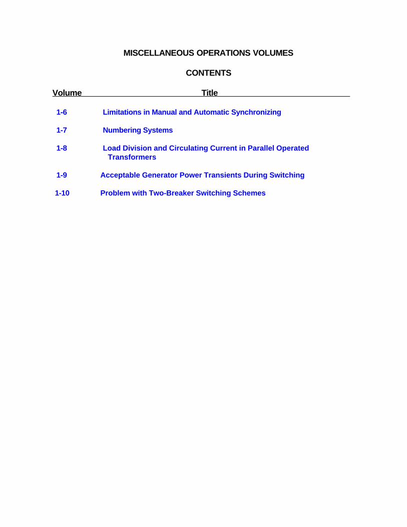
MISCELLANEOUS OPERATIONS VOLUMES
CONTENTS
Volume Title
1-6 Limitations in Manual and Automatic Synchronizing
1-7 Numbering Systems
1-8 Load Division and Circulating Current in Parallel Operated Transformers
1-9 Acceptable Generator Power Transients During Switching
1-10 Problem with Two-Breaker Switching Schemes
BUREAU OF RECLAMATION
FACILITIES INSTRUCTIONS, STANDARDS & TECHNIQUES
Volume 1-6
LIMITATIONS IN MANUAL AND
AUTOMATIC SYNCHRONIZING

LIMITATIONS IN MANUAL AND AUTOMATIC SYNCHRONIZING
In nearly all applications of automatic synchronizers, unnecessarily conservative settings have limited the usefulness of the synchronizer, and sometimes manual synchronizing can be improved.
The angular error at the instant of breaker contact closing produces mechanical shock and is therefore more serious than equal power swings from frequency difference alone. When synchronizing manually, since it becomes difficult to accurately allow for breaker closing time at the higher frequency differences, manual synchronizing is ordinarily limited to one slip cycle in 8 seconds or more. If the circuit breaker closing time is slow, erratic, or unknown, or if the operator is unfamiliar with the equipment, a very slow moving needle must be chosen. To realize the full benefit of an automatic synchronizer, it must perform faster, more accurately, and more consistently than can be expected of manual synchronizing. This is feasible for several reasons:
• The synchronizer automatically antici-pates the proper closing instant, up tothe preset cutoff frequency difference,eliminating personal error.
• Most synchronizers are equipped toautomatically change the advancetime to suit the circuit breaker se-lected, personal error due to unfamil-iarity with equipment is eliminated.
The only limitation then, is error from magnitude of power swings because of frequency difference. The highest, reasonably possible, rate of control within this limitation is desirable, to reduce synchronizing delay during emergencies. The cutoff frequency difference of one-fourth hertz (one slip cycle in 4 seconds) accommodates the governors of most units without delay and will keep power swings, due to synchronizing, within conservative limits. (The automatic synchromizer can still be used to
1
perform a smoother operation when desired, by releasing control of the circuit breaker to the synchronizer only when the frequency difference is as low as desired).
The following will help determine when automatic synchronizers have unnecessarily conservative settings, or when manual synchronizing can be improved. Some synchronizing operations produce neither power swings nor sound; some produce power swings but no sound; and some produce both power swings and sound:
THE FIRST CASE. - A slow perfect shot requires no illustration. (Slight sound may be produced by otherwise perfect synchronizing, if the running and incoming machine voltages are not equal. This is of no importance if the voltages differ by no more than 10 percent.)
THE SECOND CASE. - This operation is accept-able, as the power swings due to initial frequency difference are too slow to produce mechanical shock (fig. 1, QUIET). Damage from this source is unlikely although, for smooth system operation it is desirable to limit the swings well below nameplate rating.
THE THIRD CASE. -This represents a mechanical shock and a vibration to the machine which could be severe and damaging (fig. 1, MECHANICAL SHOCK). Limiting this shock by reasonably accurate synchronizing is very important.
Closing the circuit breaker with voltages 15 degrees out of phase (fig. 1, MECHANICAL SHOCK), even with very small difference in frequency, produces power swings as great as closing the circuit breaker exactly at synchronism when the synchroscope is making one revolution in 2 seconds (fig. 1, QUIET). Fifteen degrees is a very small angle on a synchroscope dial, while one revolution in 2 seconds is a greater frequency difference than one ordinarily attempts to synchronize manually.
(FIST 1-6 1/90)

Figure 1. - Typical synchronizing power swings
Thus, closing the circuit breaker contacts at the proper instant is more important than having a very low-frequency difference. The two limitations go together to prevent accurate manual synchronizing with high-frequency differences due to the difficulty of estimating the required advance, plus the mental reaction error.
Synchronizing power-swing plots of several Bureau generators (fig. 2) represent circuit breaker contact closure exactly synchronized, with the synchroscope rotating at one revolution in 4 seconds. The maximum power swings are all within 15 to 22 percent of the nameplate rating of the respective generator. Thus, the same tolerance applies satisfactorily to many sizes of synchronizing hydropower generators.
Each power-swing curve (fig. 2) is approximately one-half of what it would be if each generator were synchronized to an infinitely large generator instead of one of identical size, assuming the same frequency difference. Effectively this is the condition when a generator is synchronized to a
large number of generators in the same plant. Then, although the unit wattmeter makes a visible swing, it and the currents and stresses are still well within normal range. The swing is largely confined to within the plant, and only a small percent of it reaches the transmission lines.
Usually, after an interruption, the generators are individually synchronized to the transmission line, except in plants with units too small to absorb the charging current of the transmission line. Then, two or more units on one bus may be synchronized to the line. The maximum power swing is shown (fig. 3) which would be obtained if a 75000 kW plant were synchronized to a 240-km (149-mi) 230-kV transmission line. The corresponding swing is only 9.5 degrees (20 MW). A swing of the samemagnitude would be produced by closing the switch with no frequency difference but with the voltages 9.5 degrees out of phase. The first case would be quiet, but in the later case a slight sound would be produced because the power was changed abruptly from 0 to 20 MW. In either
(FIST 1-6 1/90) 2
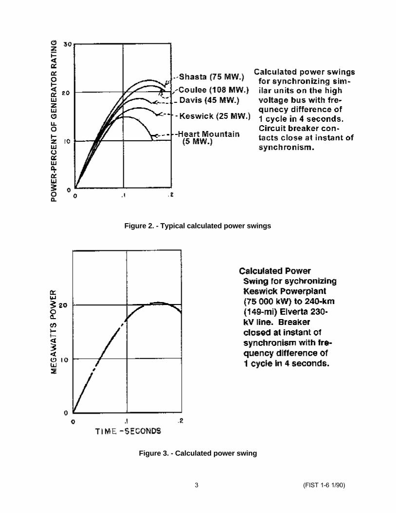
Figure 2. - Typical calculated power swings
Figure 3. - Calculated power swing
3 (FIST 1-6 1/90)

case, the final generator loading after the swings stopped, would be of some very small value corresponding to the speed level adjustment.
In spite of a popular notion that the incoming generator frequency should be slightly "fast" when being synchronized to a heavily loaded system, actually this is not true of the usual system. The transmission-line load, swings nearer to the stability limit if an incoming gener-ator is synchronized with the synchroscope rotating in the FAST direction than if it were rotating at the same speed in the SLOW direc-
tion. The difference depends upon the rate of decay of the power swings (fig. 4). The rate of decay of the swings is from actual measurements on a Reclamation system. This influence is negligible compared with the influence of angular error and frequency difference. If angular error and frequency difference are held within recommended limits, no time need be wasted obtaining synchroscope rotation in a particular direction. Synchronizing will be satisfactory for either direction.
Figure 4. - Power swings of incoming machine.
(FIST 1-6 1/90) 4
BUREAU OF RECLAMATION
FACILITIES INSTRUCTIONS, STANDARDS & TECHNIQUES
Volume 1-7
NUMBERING SYSTEMS

NUMBERING SYSTEMS
1.-STANDARD TRANSMISSION LINE STRUCTURE NUMBERING SYSTEM
The standard structure numbering system used on all Reclamation transmission line structures was adopted by the Bureau of Reclamation in 1948. The system consists of two numbers
25arranged thus: or 25/ 7 which represents7
the mile distance and number of structures from a reference point. This example describes the seventh structure beyond the 25th mile from the beginning, or the powerplant end of the power-line. Structure within the first mile should be
0 0numbered , , or 0/ 1, 0/ 2 and so on. The 1 2
numbering should start at a significant location such as a major substation or switching station. The numbers should appear both at the base of the structure, and on the sign at the top, If one is provided for identification by aerial patrol.
2.-STANDARD SWITCH NUMBERING SYSTEM
Switch numbers are normally assigned by the Division of Engineering, Facilities Engineering Branch, Denver Office, during design, (fig. 1a) to maintain a uniform standard on all projects. Any changes or additions made should be shown on a marked copy of the single-line diagram and sent to the Division of Engineering, Attention: Code D-5210, Denver Office, so the drawings can be kept up to date.
1 (FIST 1-7 1/90)

Figure 1a. - Standard switch numbering system for operating purposes.
2

EXPLANATION OF SYMBOLS
1. The switch-numbering scheme described herein and illustrated on the accompanying diagram of a hypothetical power system is to beused as a standard system for operating purposes by all Bureau projects. Switches not involved in system operation, such as low-voltage station-service switches, are not required to be numbered by this system.
2. The use of this numbering system will not affect the designations assigned by the design engineers and used for construction purpose. Switches will therefore have two designations.
3. The switch number consists of three symbols. The first symbol identifies an individual circuit and may vary from 1 to 99. The following rules apply to the assigning of the first symbol:
A. It is a preferred that each circuit in a station has a different first symbol. Circuits eminating from a transformer are all considered as one circuit for purposes of numbering.
B. Where feasible, circuits on generating units will carry the same first symbol as the generator.
C. In substations it is preferred that low number first symbols be used on the highest voltage circuits with first symbols increasing as you work toward progressively lower voltage circuits. It is a good plan to reserve some numbers between high and low voltage series for possible future extensions.
D. At powerplants start with the lowest number at the generator or transformer neutral and work outward on the circuit. Where there are two powerplants qn the same location, the first symbol may be a letter and a number, such as N6, R1, L4, etc.
E. Line sectionalizing switches not located at substations should use the line structure number (nearest mile) as the first symbol. The other symbols will be the same as for powerplants and substations. Switches at tap points on a line should be numbered the same as at substations and the tap point assigned a name.
4. The second symbol designates the general voltage classification of tile circuit as follows:
0 and 1 0 to) 9.0 KV 2 and 3 10 to 29 KV 4 and 5 30 to 99 KV 6 and 7 100 to 199 KV 8 and 9 200 KV and above
is used to discriminate between lThe third symbo.5several switches or devices in a circuit.
Numbers 2,4,6 and 8 designate circuit breakers or other automatic devices. The preferred use of these last symbols is as follows:
Use 2 for main breaker in any bus arrangement that permits isolating the breaker by tying its circuit to another breaker.
Use 4 for breaker in any single bus tarrangemen .
Use 6 for transfer bus breaker or bus tie breaker
Use 8 for drop-out type breaker. Label interruptor switches as circuit breakers if they are rated for load breaking.
Numbers 0,1,3,5,7 and 9 designate disconnecting switches. The preferred use of these last symbols is as follows: Use 0 for grounding switches Use 9 for by-pass switches Breaker disconnecting switches should be assigned the odd numbers on each side of the breaker using the higher number on the bus side of the breager. Exception: on bus tie breakers, the disconnecting switches should have the same last symbol as switches in other bays that are connected directly to the main and transfer buses. Label fuses as disconnects.
Numbers decrease as you move from the starting point on a bus toward any of the following: A. Load circuit B. Transmission line C. Secondary or tertiary of a transformer D. Generating unit
When moving from a bus to the primary of a transformer it may be necessary to deviate from this rule in some instances.
6. Example of switch numbering. The symbols for Big Bend Powerplant Switch No. 1351 are determined as follows:
A. The first symbol is 13 indicating circuit 13
B. The second symbol is 5 indicating 30 to 99 KV (69 KV)
C. The third symbol is 1 indicating a disconnect switch.
Figure 1a. - Standard switch numbering system for operating purposes.
3
BUREAU OF RECLAMATION
FACILITIES INSTRUCTIONS, STANDARDS & TECHNIQUES
Volume 1-8
LOAD DIVISION AND CIRCULATINGCURRENT IN PARALLEL OPERATED
TRANSFORMERS
LOAD DIVISION AND CIRCULATING CURRENT IN PARALLEL-OPERATEDTRANSFORMERS
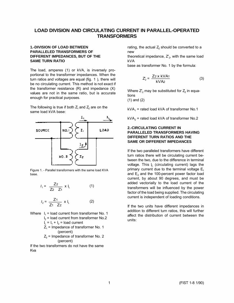
1.-DIVISION OF LOAD BETWEEN PARALLELED TRANSFORMERS OF DIFFERENT IMPEDANCES, BUT OF THE SAME TURN RATIO
The load, amperes (1) or kVA, is inversely pro-portional to the transformer impedances. When the turn ratios and voltages are equal (fig. 1 ), there will be no circulating current. This method is not exact if the transformer resistance (R) and impedance (X) values are not in the same ratio, but is accurate enough for practical purposes.
The following is true if both Z1 and Z2 are on the same load kVA base:
Figure 1. - Parallel transformers with the same load KVA base.
I1 = Z Z Z
2
2 1+ x IL (1)
I2 = Z Z Z
1
1 2+ x IL (2)
Where I1 = load current from transformer No. 1 I2 = load current from transformer No.2 IL = I1 + I2 = load current Z1 = Impedance of transformer No. 1
(percent) Z2 = Impedance of transformer No. 2
(percent) If the two transformers do not have the same Kva
rating, the actual Z2 should be converted to a new theoretical impedance, Z'2, with the same load kVA base as transformer No. 1 by the formula:
Z2 x kVA1Z'2 = (3)kVA2
Where Z'2 may be substituted for Z2 in equa-tions (1) and (2)
kVA1 = rated load kVA of transformer No.1
kVA2 = rated load kVA of transformer No.2
2.-CIRCULATING CURRENT IN PARALLELED TRANSFORMERS HAVING DIFFERENT TURN RATIOS AND THE SAME OR DIFFERENT IMPEDANCES
If the two paralleled transformers have different turn ratios there will be circulating current be-tween the two, due to the difference in terminal voltage. This lC (circulating current) lags the primary current due to the terminal voltage E1 and E2 and the 100-percent power factor load current, by about 90 degrees, and must be added vectorially to the load current of the transformers will be influenced by the power factor of the load being supplied. The circulating current is independent of loading conditions.
If the two units have different impedances in addition to different turn ratios, this will further affect the distribution of current between the units:
1 (FIST 1-8 1/90)

BUREAU OF RECLAMATION
FACILITIES INSTRUCTIONS, STANDARDS & TECHNIQUES
Volume 1-9
ACCEPTABLE GENERATOR POWERTRANSIENTS DURING SWITCHING

ACCEPTABLE GENERATOR POWER TRANSIENTS DURING SWITCHING
There are three principal types of transient • If a generator has been restudied for unit disturbances that affect generator stability. One uprating, generator power transients up to of these is from switching operations. The steady- 0.5 per unit of the uprated value are state stability limit for the operating condition acceptable. after switching takes place, and the difference between initial and steady-state operating angles, • Studies should be made to ensure that determines the amount of power transferable the 0.5 per unit level will not be without loss of synchronism. exceeded whenever changes are made
in switching procedure or station The following criteria should be followed with configuration. regard to acceptable generator power transients d u e t o s w i t c h i n g o p e r a t i o n s : • The above limits apply to routine planned
line switching operations. Emergency • The maximum acceptable level for gen- operation requirements power transients
erator power transients due to planned up to 1.0 per unit. switching, with the unit operating at an allowable load, is 0.5 per unit based on the original unit rating.
1 (FIST 1-9 1/90)
BUREAU OF RECLAMATION
FACILITIES INSTRUCTIONS, STANDARDS & TECHNIQUES
Volume 1-10
PROBLEM WITH TWO BREAKERTRIPPING SCHEMES
PROBLEM WITH TWO-BREAKER TRIPPING SCHEMES
An operational problem can occur with switching schemes such as ring bus and breaker-and-a-half schemes that require the tripping of two circuit breakers to clear a line fault.
In the early 1970's, a circuit breaker in a 100-kV ring bus was standing closed with disconnect switches on either side open, isolating the breaker for maintenance when a fault occurred on its associated line. The companion breaker tripped to clear the fault, but an "a" contact in the breaker under clearance prevented the line relay
seal-in circuit from resetting, thereby preventing initial attempts to close the breaker that tripped.
Clearance procedures for breakers of these two-breaker schemes should include the removal of these "a" contacts from service. The preferred method to prevent this problem is to install control switches to permit isolating the circuit breaker auxiliary switch contacts without circuit breaker auxiliary switch contacts without disconnecting leads.
1 (FIST 1-10 1/90)