Embed Size (px)
DESCRIPTION
Dell Vostro Manual
Citation preview
Dell™ Vostro™ 1014/1015 Service Manual
Notes, Cautions, and Warnings
If you purchased a Dell™ n Series computer, any references in this document to Microsoft® Windows® operating systems are not applicable.
Information in this document is subject to change without notice. © 2009 Dell Inc. All rights reserved.
Reproduction of this material in any manner whatsoever without the written permission of Dell Inc. is strictly forbidden.
Trademarks used in this text: Dell, the DELL logo, and Vostro, are trademarks of Dell Inc.; Intel, Celeron, and Core are either trademarks or registered trademarks of Intel Corporation; Bluetooth is a registered trademark owned by Bluetooth SIG, Inc. and is used by Dell under license; Microsoft, Windows, Windows Vista, and the Windows Vista start button are either trademarks or registered trademarks of Microsoft Corporation in the United States and/or other countries; Adobe, the Adobe logo, and Adobe Flash Player are trademarks of Adobe Systems Incorporated.
Other trademarks and trade names may be used in this document to refer to either the entities claiming the marks and names or their products. Dell Inc. disclaims any proprietary interest in trademarks and trade names other than its own.
November 2009 Rev. A00
Working on Your Computer
Adding and Replacing Parts
Specifications
Diagnostics
System Setup
NOTE: A NOTE indicates important information that helps you make better use of your computer.
CAUTION: A CAUTION indicates potential damage to hardware or loss of data if instructions are not followed.
WARNING: A WARNING indicates a potential for property damage, personal injury, or death.
Back to Contents Page
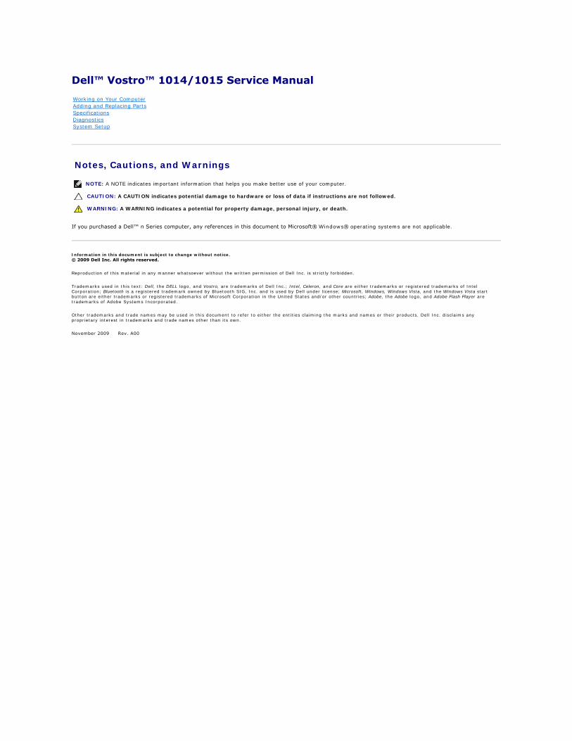
Access Panel Dell™ Vostro™ 1014/1015 Service Manual
Removing the Access Panel
1. Follow the procedures in Before Working Inside Your Computer. 2. Remove the battery from the computer.
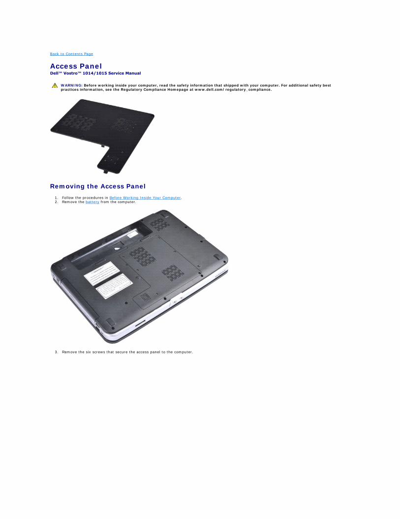
3. Remove the six screws that secure the access panel to the computer.
WARNING: Before working inside your computer, read the safety information that shipped with your computer. For additional safety best practices information, see the Regulatory Compliance Homepage at www.dell.com/regulatory_compliance.
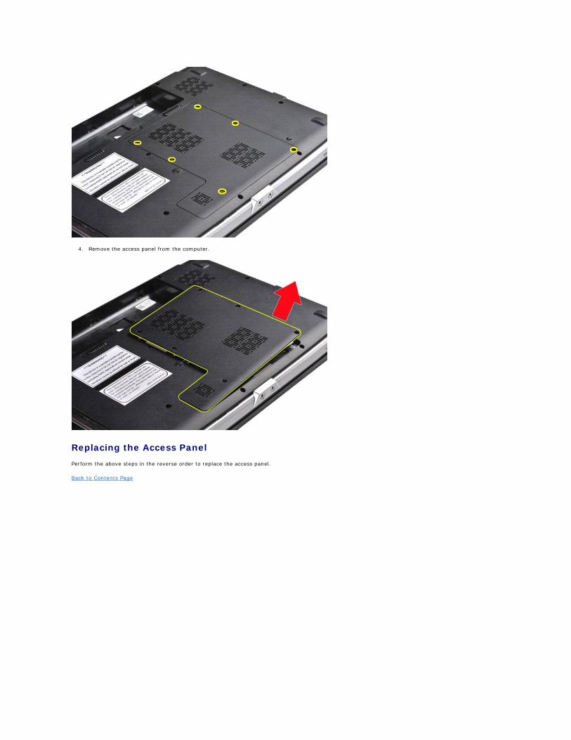
4. Remove the access panel from the computer.
Replacing the Access Panel
Perform the above steps in the reverse order to replace the access panel.
Back to Contents Page
Back to Contents Page
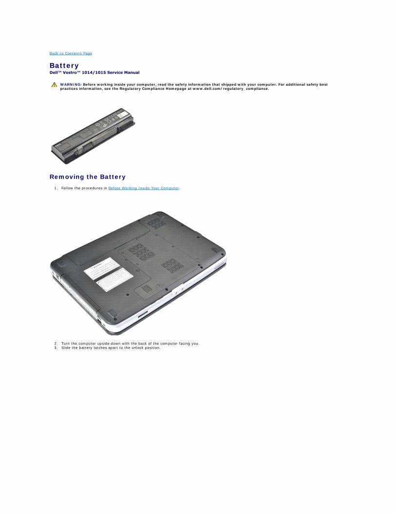
Battery Dell™ Vostro™ 1014/1015 Service Manual
Removing the Battery
1. Follow the procedures in Before Working Inside Your Computer.
2. Turn the computer upside-down with the back of the computer facing you. 3. Slide the battery latches apart to the unlock position.
WARNING: Before working inside your computer, read the safety information that shipped with your computer. For additional safety best practices information, see the Regulatory Compliance Homepage at www.dell.com/regulatory_compliance.
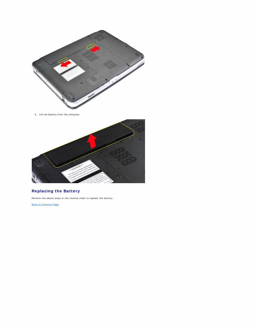
3. Lift the battery from the computer.
Replacing the Battery
Perform the above steps in the reverse order to replace the battery.
Back to Contents Page
Back to Contents Page
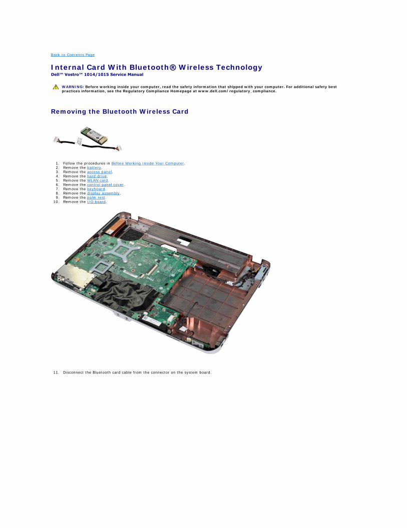
Internal Card With Bluetooth® Wireless Technology Dell™ Vostro™ 1014/1015 Service Manual
Removing the Bluetooth Wireless Card
1. Follow the procedures in Before Working Inside Your Computer. 2. Remove the battery. 3. Remove the access panel. 4. Remove the hard drive. 5. Remove the WLAN card. 6. Remove the control panel cover. 7. Remove the keyboard. 8. Remove the display assembly. 9. Remove the palm rest.
10. Remove the I/O board.
11. Disconnect the Bluetooth card cable from the connector on the system board.
WARNING: Before working inside your computer, read the safety information that shipped with your computer. For additional safety best practices information, see the Regulatory Compliance Homepage at www.dell.com/regulatory_compliance.
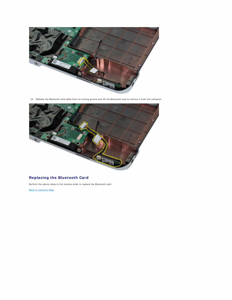
12. Release the Bluetooth card cable from its routing groove and lift the Bluetooth card to remove it from the computer.
Replacing the Bluetooth Card
Perform the above steps in the reverse order to replace the Bluetooth card.
Back to Contents Page
Back to Contents Page
Coin-Cell Battery Dell™ Vostro™ 1014/1015 Service Manual
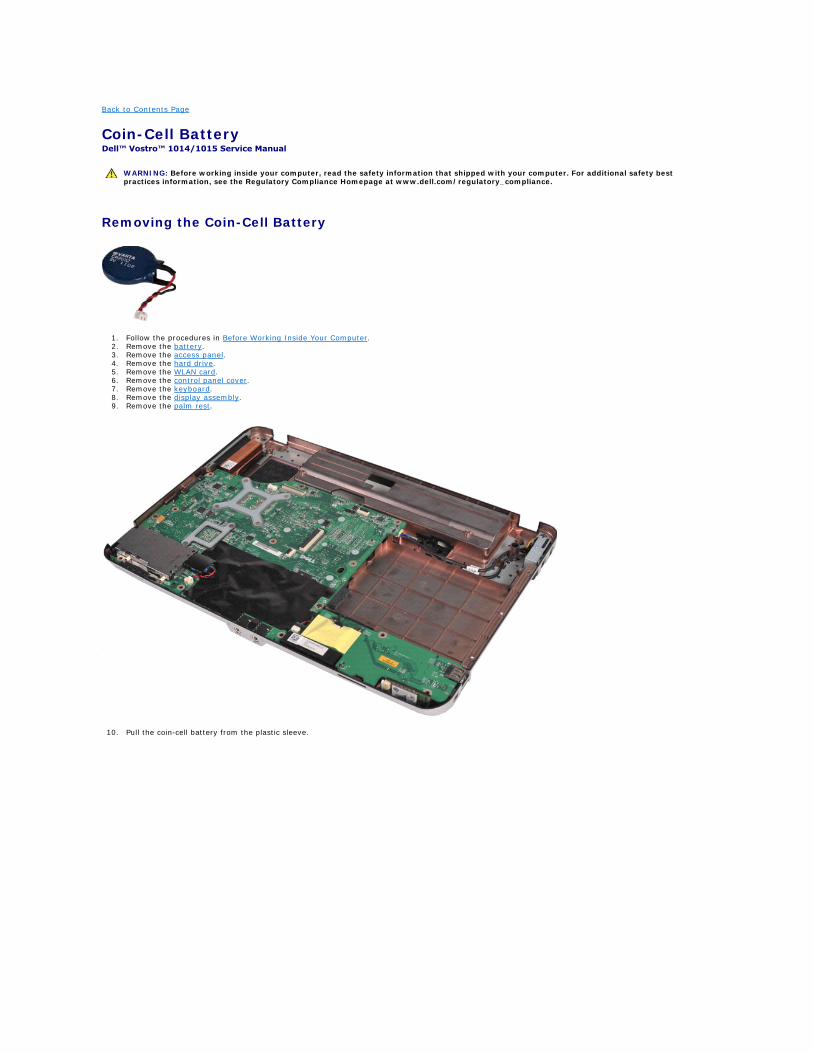
Removing the Coin-Cell Battery
1. Follow the procedures in Before Working Inside Your Computer. 2. Remove the battery. 3. Remove the access panel. 4. Remove the hard drive. 5. Remove the WLAN card. 6. Remove the control panel cover. 7. Remove the keyboard. 8. Remove the display assembly. 9. Remove the palm rest.
10. Pull the coin-cell battery from the plastic sleeve.
WARNING: Before working inside your computer, read the safety information that shipped with your computer. For additional safety best practices information, see the Regulatory Compliance Homepage at www.dell.com/regulatory_compliance.
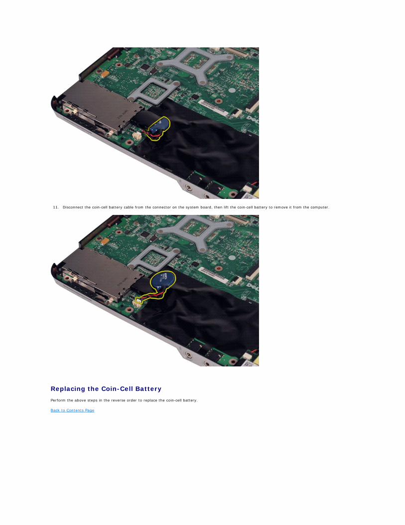
11. Disconnect the coin-cell battery cable from the connector on the system board, then lift the coin-cell battery to remove it from the computer.
Replacing the Coin-Cell Battery
Perform the above steps in the reverse order to replace the coin-cell battery.
Back to Contents Page
Back to Contents Page
Control Panel Cover Dell™ Vostro™ 1014/1015 Service Manual
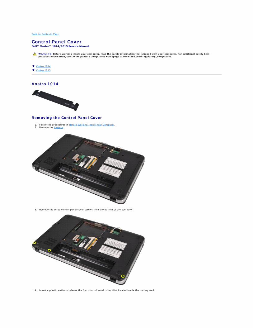
Vostro 1014
Removing the Control Panel Cover
1. Follow the procedures in Before Working Inside Your Computer. 2. Remove the battery.
3. Remove the three control panel cover screws from the bottom of the computer.
4. Insert a plastic scribe to release the four control panel cover clips located inside the battery well.
WARNING: Before working inside your computer, read the safety information that shipped with your computer. For additional safety best practices information, see the Regulatory Compliance Homepage at www.dell.com/regulatory_compliance.
Vostro 1014
Vostro 1015
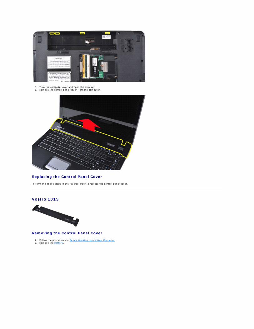
5. Turn the computer over and open the display. 6. Remove the control panel cover from the computer.
Replacing the Control Panel Cover
Perform the above steps in the reverse order to replace the control panel cover.
Vostro 1015
Removing the Control Panel Cover
1. Follow the procedures in Before Working Inside Your Computer. 2. Remove the battery.
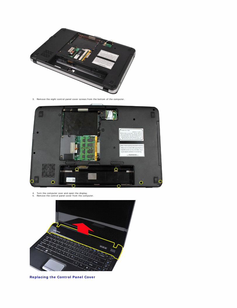
3. Remove the eight control panel cover screws from the bottom of the computer.
4. Turn the computer over and open the display. 5. Remove the control panel cover from the computer.
Replacing the Control Panel Cover

Perform the above steps in the reverse to replace the control panel cover.
Back to Contents Page
Back to Contents Page
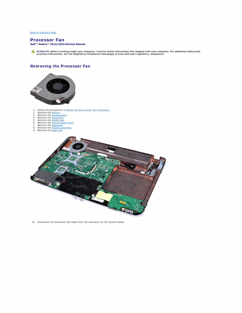
Processor Fan Dell™ Vostro™ 1014/1015 Service Manual
Removing the Processor Fan
1. Follow the procedures in Before Working Inside Your Computer. 2. Remove the battery. 3. Remove the access panel. 4. Remove the hard drive. 5. Remove the WLAN card. 6. Remove the control panel cover. 7. Remove the keyboard. 8. Remove the display assembly. 9. Remove the palm rest.
10. Disconnect the processor fan cable from the connector on the system board.
WARNING: Before working inside your computer, read the safety information that shipped with your computer. For additional safety best practices information, see the Regulatory Compliance Homepage at www.dell.com/regulatory_compliance.
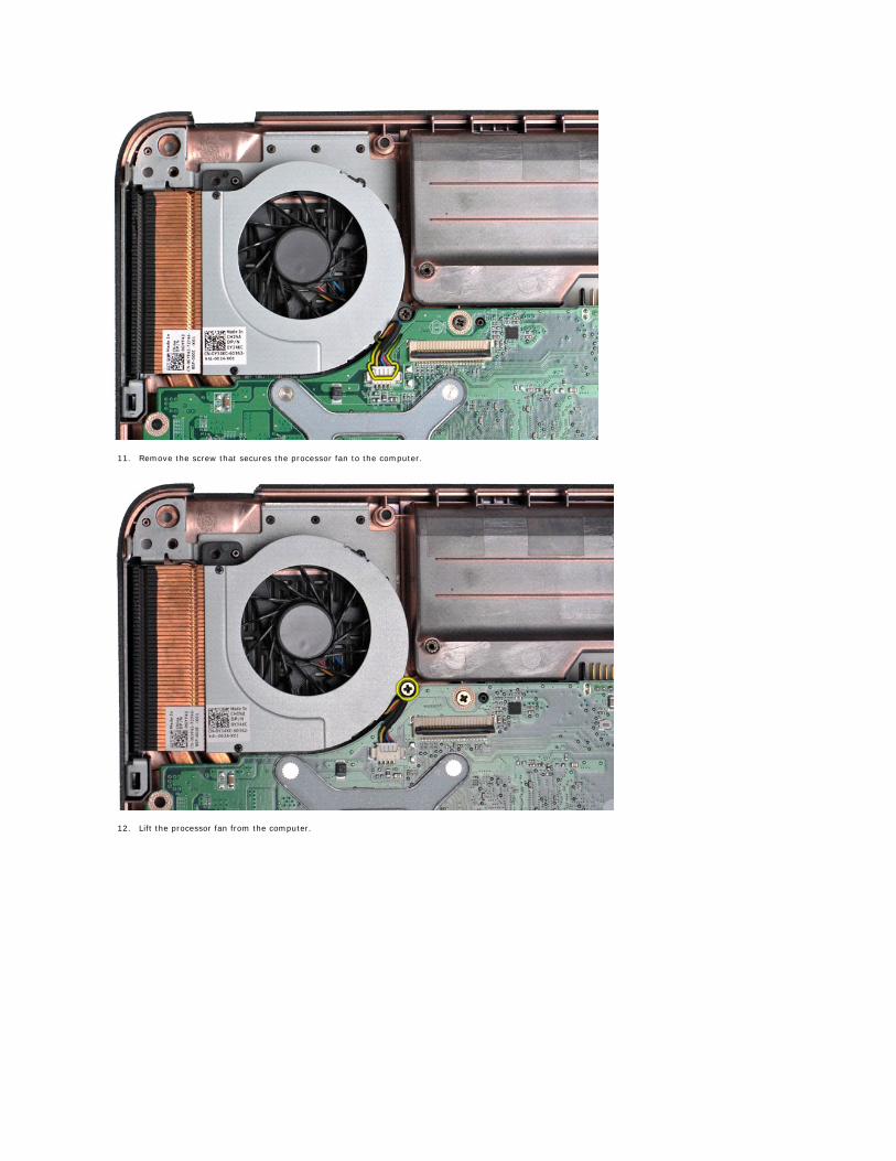
11. Remove the screw that secures the processor fan to the computer.
12. Lift the processor fan from the computer.
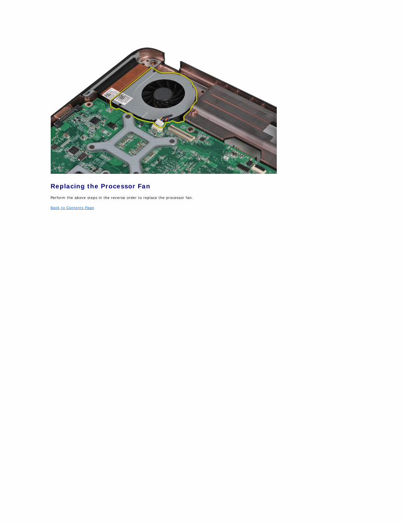
Replacing the Processor Fan
Perform the above steps in the reverse order to replace the processor fan.
Back to Contents Page
Back to Contents Page
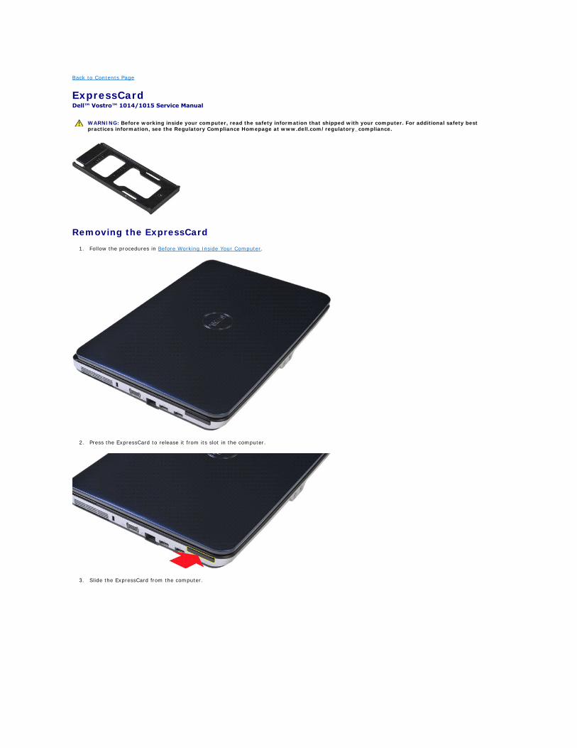
ExpressCard Dell™ Vostro™ 1014/1015 Service Manual
Removing the ExpressCard
1. Follow the procedures in Before Working Inside Your Computer.
2. Press the ExpressCard to release it from its slot in the computer.
3. Slide the ExpressCard from the computer.
WARNING: Before working inside your computer, read the safety information that shipped with your computer. For additional safety best practices information, see the Regulatory Compliance Homepage at www.dell.com/regulatory_compliance.
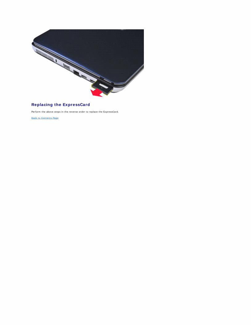
Replacing the ExpressCard
Perform the above steps in the reverse order to replace the ExpressCard.
Back to Contents Page
Back to Contents Page
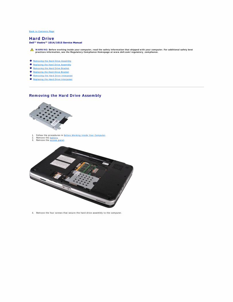
Hard Drive Dell™ Vostro™ 1014/1015 Service Manual
Removing the Hard Drive Assembly
1. Follow the procedures in Before Working Inside Your Computer. 2. Remove the battery. 3. Remove the access panel.
4. Remove the four screws that secure the hard drive assembly to the computer.
WARNING: Before working inside your computer, read the safety information that shipped with your computer. For additional safety best practices information, see the Regulatory Compliance Homepage at www.dell.com/regulatory_compliance.
Removing the Hard Drive Assembly
Replacing the Hard Drive Assembly
Removing the Hard Drive Bracket
Replacing the Hard Drive Bracket
Removing the Hard Drive Interposer
Replacing the Hard Drive Interposer
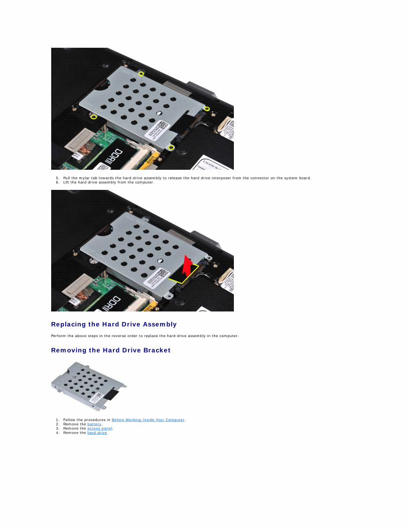
5. Pull the mylar tab towards the hard drive assembly to release the hard drive interposer from the connector on the system board. 6. Lift the hard drive assembly from the computer.
Replacing the Hard Drive Assembly
Perform the above steps in the reverse order to replace the hard drive assembly in the computer.
Removing the Hard Drive Bracket
1. Follow the procedures in Before Working Inside Your Computer. 2. Remove the battery. 3. Remove the access panel. 4. Remove the hard drive.
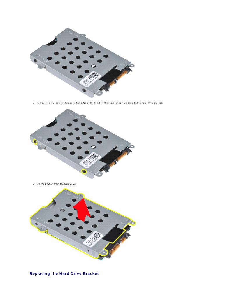
5. Remove the four screws, two on either sides of the bracket, that secure the hard drive to the hard drive bracket.
6. Lift the bracket from the hard drive.
Replacing the Hard Drive Bracket
Perform the above step in the reverse order to replace the hard drive into the hard drive bracket.
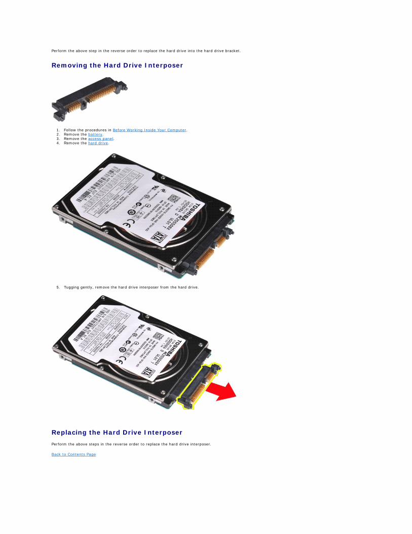
Removing the Hard Drive Interposer
1. Follow the procedures in Before Working Inside Your Computer. 2. Remove the battery. 3. Remove the access panel. 4. Remove the hard drive.
5. Tugging gently, remove the hard drive interposer from the hard drive.
Replacing the Hard Drive Interposer
Perform the above steps in the reverse order to replace the hard drive interposer.
Back to Contents Page
Back to Contents Page
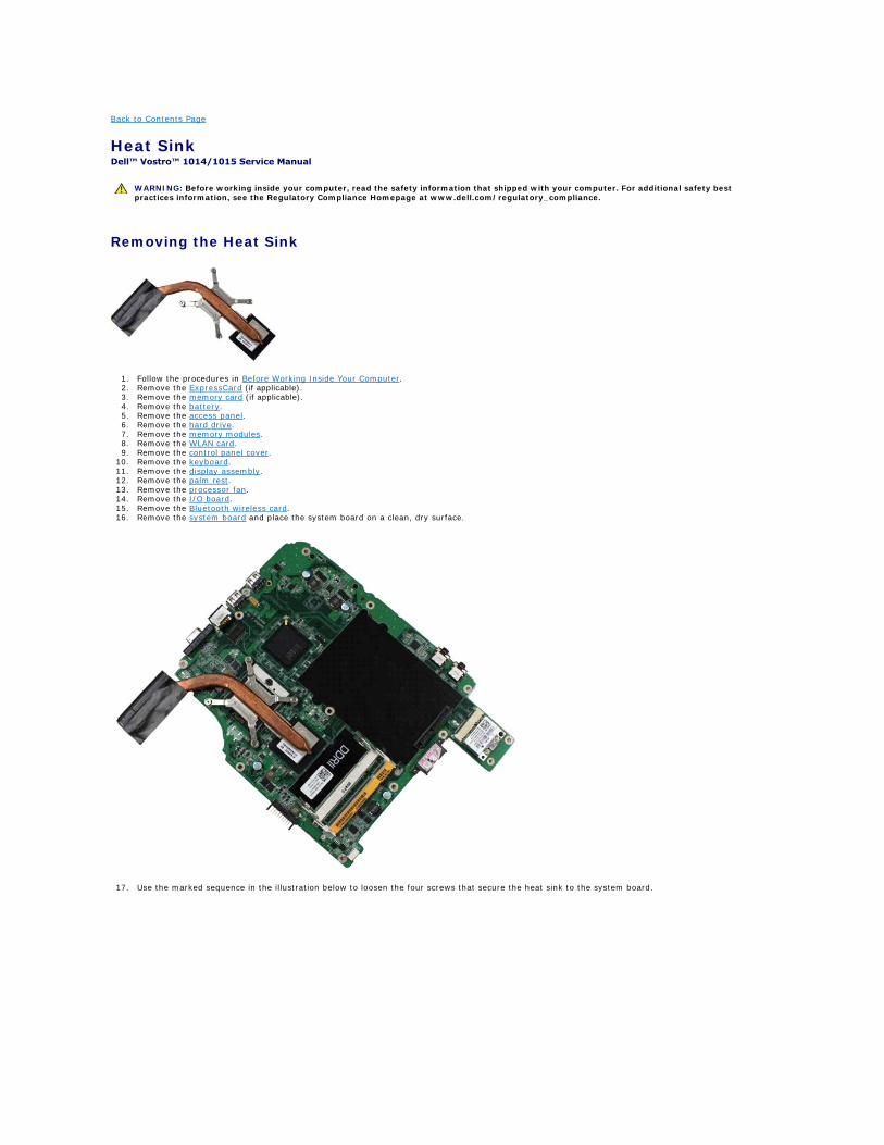
Heat Sink Dell™ Vostro™ 1014/1015 Service Manual
Removing the Heat Sink
1. Follow the procedures in Before Working Inside Your Computer. 2. Remove the ExpressCard (if applicable). 3. Remove the memory card (if applicable). 4. Remove the battery. 5. Remove the access panel. 6. Remove the hard drive. 7. Remove the memory modules. 8. Remove the WLAN card. 9. Remove the control panel cover.
10. Remove the keyboard. 11. Remove the display assembly. 12. Remove the palm rest. 13. Remove the processor fan. 14. Remove the I/O board. 15. Remove the Bluetooth wireless card. 16. Remove the system board and place the system board on a clean, dry surface.
17. Use the marked sequence in the illustration below to loosen the four screws that secure the heat sink to the system board.
WARNING: Before working inside your computer, read the safety information that shipped with your computer. For additional safety best practices information, see the Regulatory Compliance Homepage at www.dell.com/regulatory_compliance.
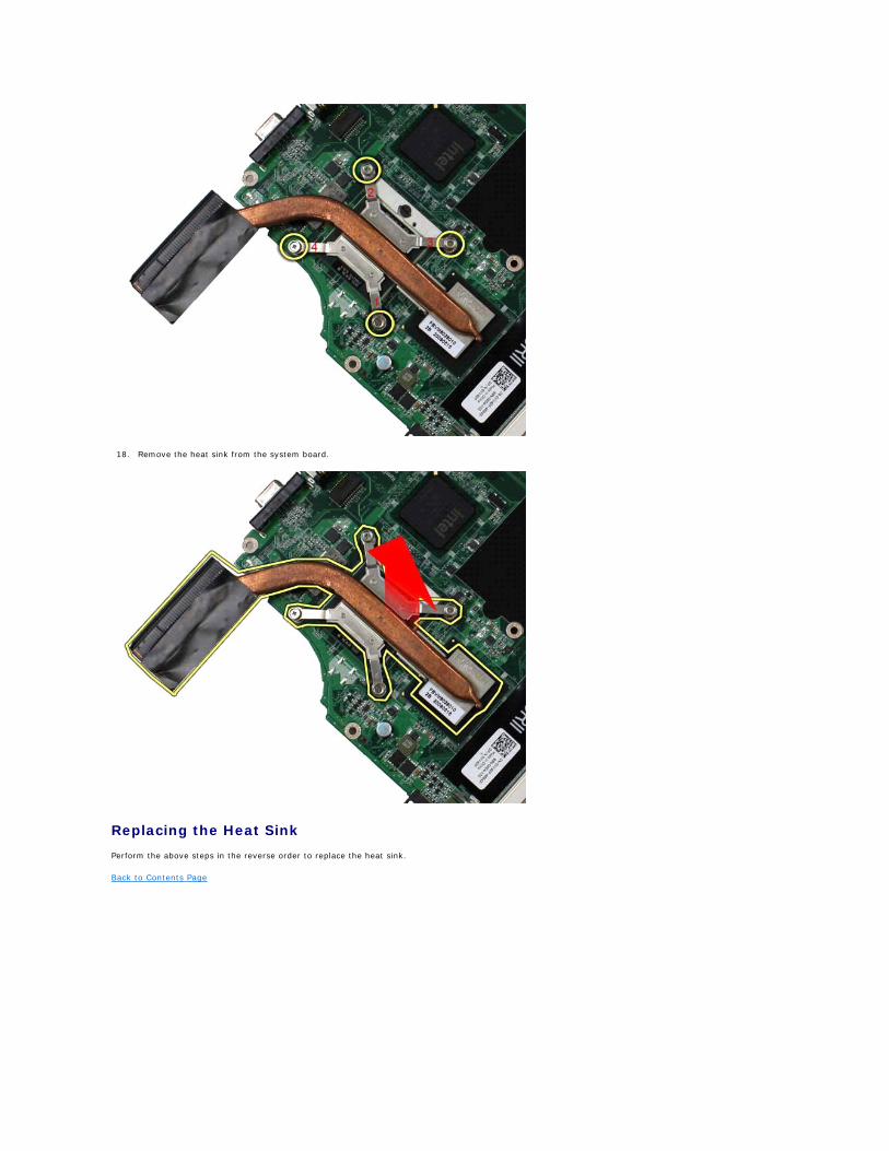
18. Remove the heat sink from the system board.
Replacing the Heat Sink
Perform the above steps in the reverse order to replace the heat sink.
Back to Contents Page
Back to Contents Page
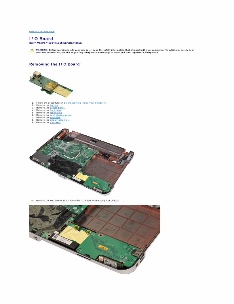
I/O Board Dell™ Vostro™ 1014/1015 Service Manual
Removing the I/O Board
1. Follow the procedures in Before Working Inside Your Computer. 2. Remove the battery. 3. Remove the access panel. 4. Remove the hard drive. 5. Remove the WLAN card. 6. Remove the control panel cover. 7. Remove the keyboard. 8. Remove the display assembly. 9. Remove the palm rest.
10. Remove the two screws that secure the I/O board to the computer chassis.
WARNING: Before working inside your computer, read the safety information that shipped with your computer. For additional safety best practices information, see the Regulatory Compliance Homepage at www.dell.com/regulatory_compliance.
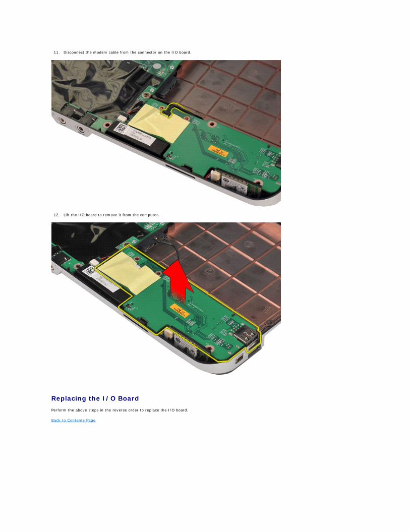
11. Disconnect the modem cable from the connector on the I/O board.
12. Lift the I/O board to remove it from the computer.
Replacing the I/O Board
Perform the above steps in the reverse order to replace the I/O board.
Back to Contents Page
Back to Contents Page
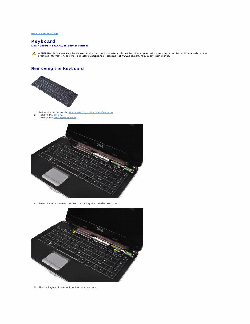
Keyboard Dell™ Vostro™ 1014/1015 Service Manual
Removing the Keyboard
1. Follow the procedures in Before Working Inside Your Computer. 2. Remove the battery. 3. Remove the control panel cover.
4. Remove the two screws that secure the keyboard to the computer.
5. Flip the keyboard over and lay it on the palm rest.
WARNING: Before working inside your computer, read the safety information that shipped with your computer. For additional safety best practices information, see the Regulatory Compliance Homepage at www.dell.com/regulatory_compliance.
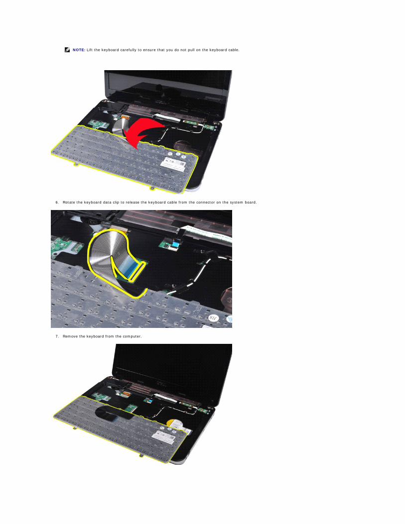
6. Rotate the keyboard data clip to release the keyboard cable from the connector on the system board.
7. Remove the keyboard from the computer.
NOTE: Lift the keyboard carefully to ensure that you do not pull on the keyboard cable.

Replacing the Keyboard
Perform the above steps in the reverse order to replace the keyboard.
Back to Contents Page
Back to Contents Page
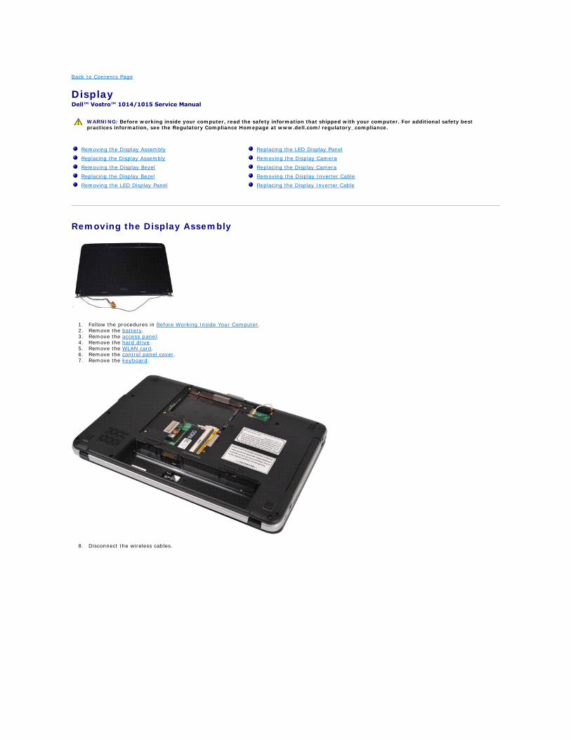
Display Dell™ Vostro™ 1014/1015 Service Manual
Removing the Display Assembly
1. Follow the procedures in Before Working Inside Your Computer. 2. Remove the battery. 3. Remove the access panel. 4. Remove the hard drive. 5. Remove the WLAN card. 6. Remove the control panel cover. 7. Remove the keyboard.
8. Disconnect the wireless cables.
WARNING: Before working inside your computer, read the safety information that shipped with your computer. For additional safety best practices information, see the Regulatory Compliance Homepage at www.dell.com/regulatory_compliance.
Removing the Display Assembly
Replacing the Display Assembly
Removing the Display Bezel
Replacing the Display Bezel
Removing the LED Display Panel
Replacing the LED Display Panel
Removing the Display Camera
Replacing the Display Camera
Removing the Display Inverter Cable
Replacing the Display Inverter Cable
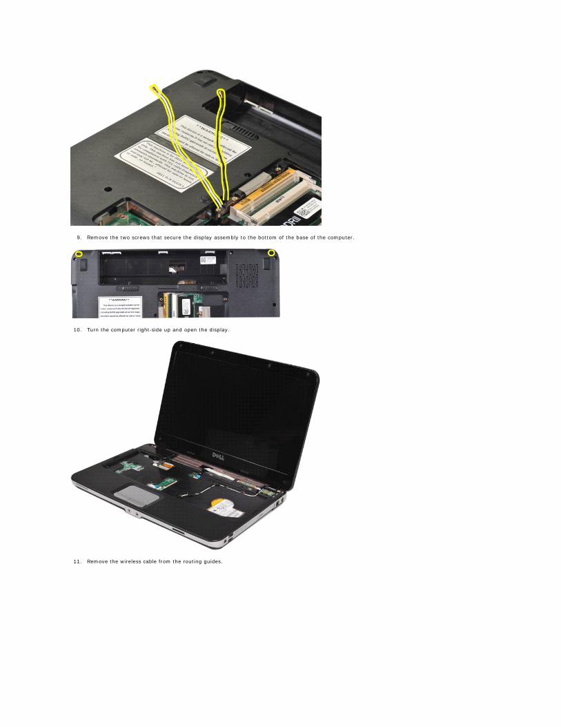
9. Remove the two screws that secure the display assembly to the bottom of the base of the computer.
10. Turn the computer right-side up and open the display.
11. Remove the wireless cable from the routing guides.
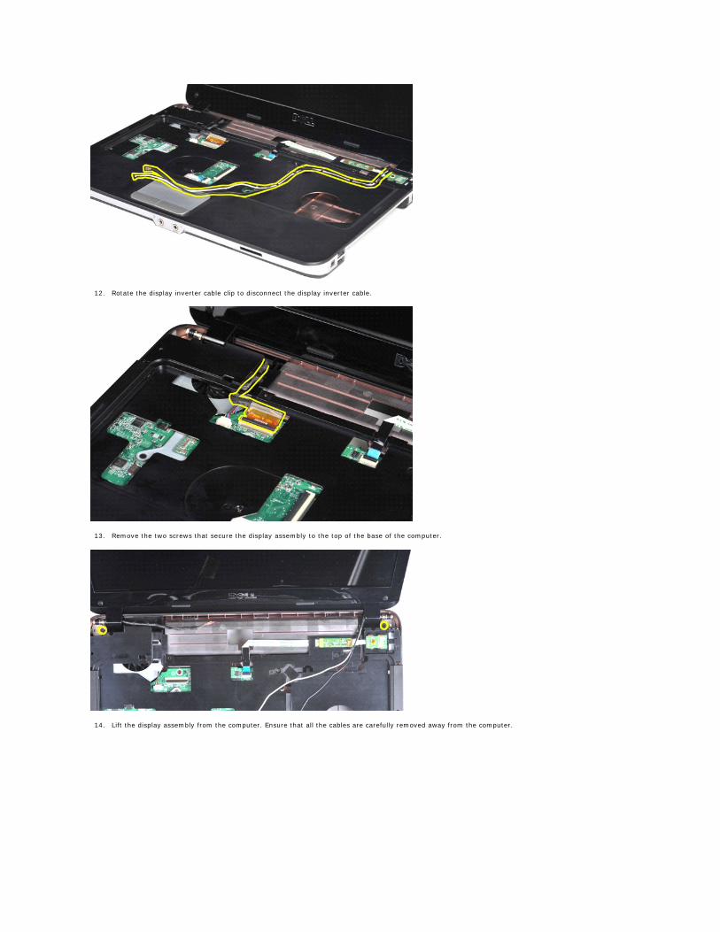
12. Rotate the display inverter cable clip to disconnect the display inverter cable.
13. Remove the two screws that secure the display assembly to the top of the base of the computer.
14. Lift the display assembly from the computer. Ensure that all the cables are carefully removed away from the computer.
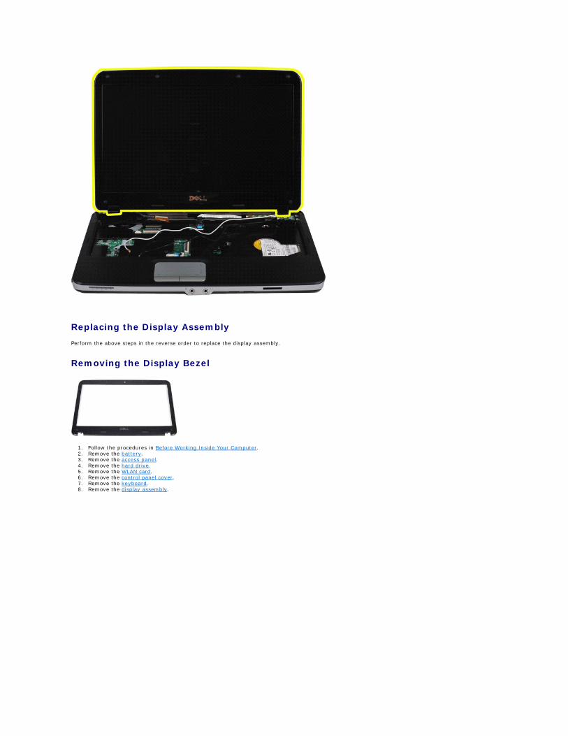
Replacing the Display Assembly
Perform the above steps in the reverse order to replace the display assembly.
Removing the Display Bezel
1. Follow the procedures in Before Working Inside Your Computer. 2. Remove the battery. 3. Remove the access panel. 4. Remove the hard drive. 5. Remove the WLAN card. 6. Remove the control panel cover. 7. Remove the keyboard. 8. Remove the display assembly.
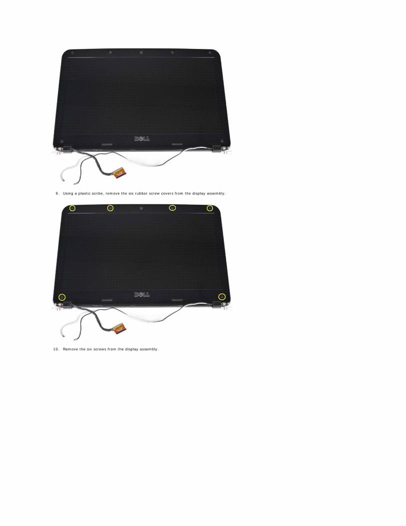
9. Using a plastic scribe, remove the six rubber screw covers from the display assembly.
10. Remove the six screws from the display assembly.
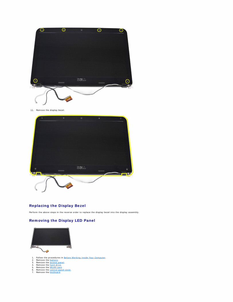
11. Remove the display bezel.
Replacing the Display Bezel
Perform the above steps in the reverse order to replace the display bezel into the display assembly.
Removing the Display LED Panel
1. Follow the procedures in Before Working Inside Your Computer. 2. Remove the battery. 3. Remove the access panel. 4. Remove the hard drive. 5. Remove the WLAN card. 6. Remove the control panel cover. 7. Remove the keyboard.
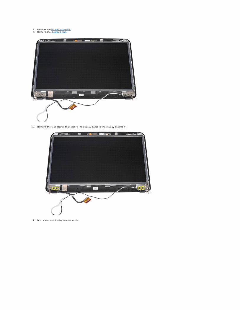
8. Remove the display assembly. 9. Remove the display bezel.
10. Remove the four screws that secure the display panel to the display assembly.
11. Disconnect the display camera cable.
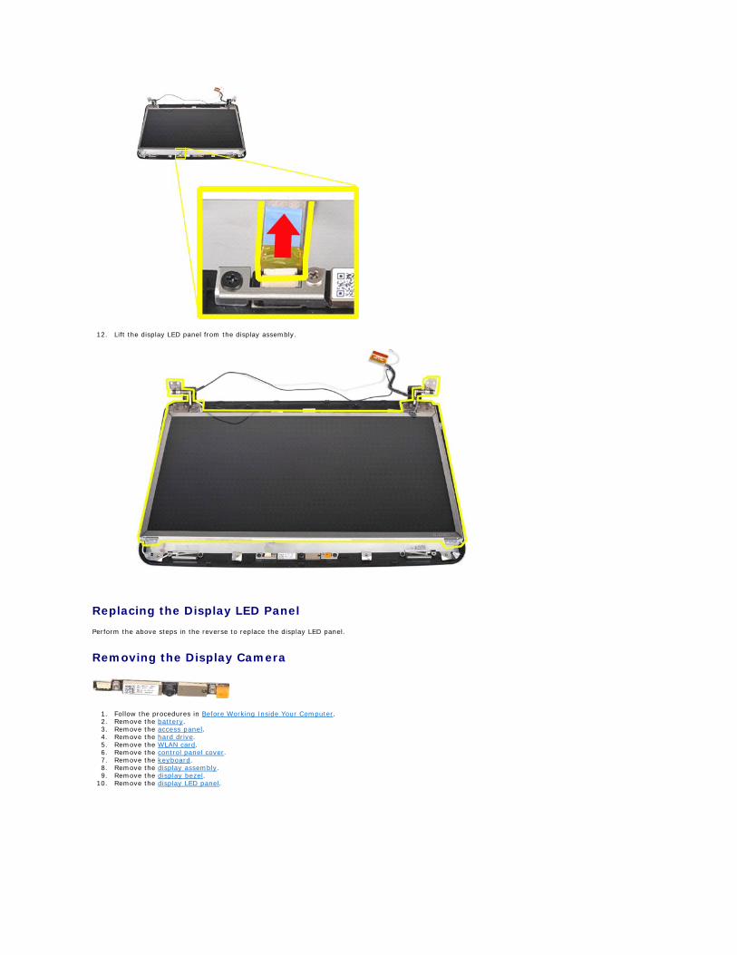
12. Lift the display LED panel from the display assembly.
Replacing the Display LED Panel
Perform the above steps in the reverse to replace the display LED panel.
Removing the Display Camera
1. Follow the procedures in Before Working Inside Your Computer. 2. Remove the battery. 3. Remove the access panel. 4. Remove the hard drive. 5. Remove the WLAN card. 6. Remove the control panel cover. 7. Remove the keyboard. 8. Remove the display assembly. 9. Remove the display bezel.
10. Remove the display LED panel.
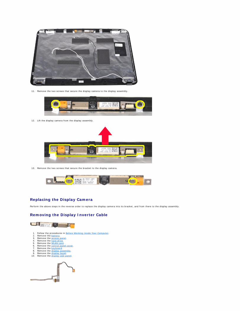
11. Remove the two screws that secure the display camera to the display assembly.
12. Lift the display camera from the display assembly.
13. Remove the two screws that secure the bracket to the display camera.
Replacing the Display Camera
Perform the above steps in the reverse order to replace the display camera into its bracket, and from there to the display assembly.
Removing the Display Inverter Cable
1. Follow the procedures in Before Working Inside Your Computer. 2. Remove the battery. 3. Remove the access panel. 4. Remove the hard drive. 5. Remove the WLAN card. 6. Remove the control panel cover. 7. Remove the keyboard. 8. Remove the display assembly. 9. Remove the display bezel.
10. Remove the display LED panel.
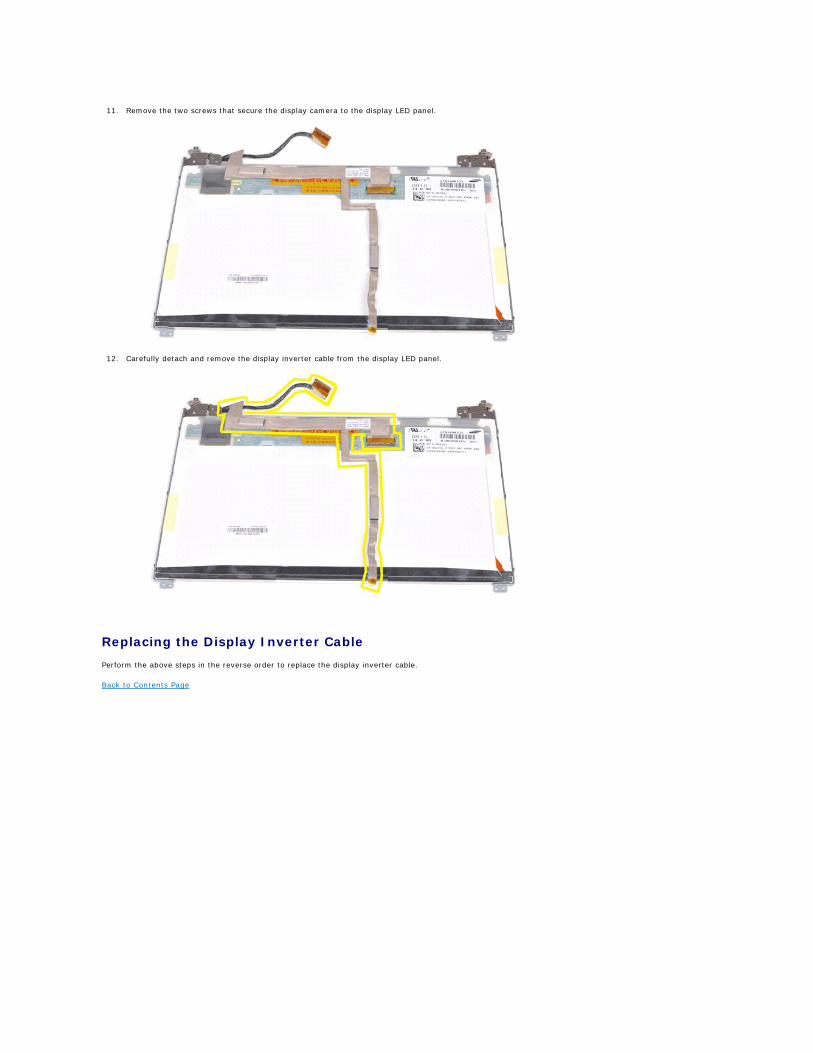
11. Remove the two screws that secure the display camera to the display LED panel.
12. Carefully detach and remove the display inverter cable from the display LED panel.
Replacing the Display Inverter Cable
Perform the above steps in the reverse order to replace the display inverter cable.
Back to Contents Page
Back to Contents Page
System Board Dell™ Vostro™ 1014/1015 Service Manual
Vostro 1014
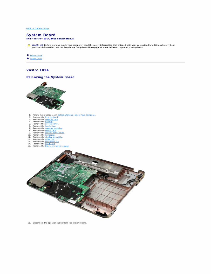
Removing the System Board
1. Follow the procedures in Before Working Inside Your Computer. 2. Remove the ExpressCard. 3. Remove the memory card. 4. Remove the battery. 5. Remove the access panel. 6. Remove the hard drive. 7. Remove the memory modules. 8. Remove the WLAN card. 9. Remove the control panel cover.
10. Remove the keyboard. 11. Remove the display assembly. 12. Remove the palm rest. 13. Remove the processor fan. 14. Remove the I/O board. 15. Remove the Bluetooth wireless card.
16. Disconnect the speaker cables from the system board.
WARNING: Before working inside your computer, read the safety information that shipped with your computer. For additional safety best practices information, see the Regulatory Compliance Homepage at www.dell.com/regulatory_compliance.
Vostro 1014
Vostro 1015
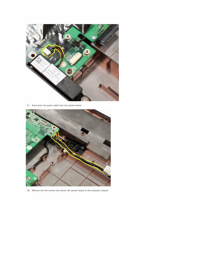
17. Disconnect the power cable from the system board.
18. Remove the five screws that secure the system board to the computer chassis.
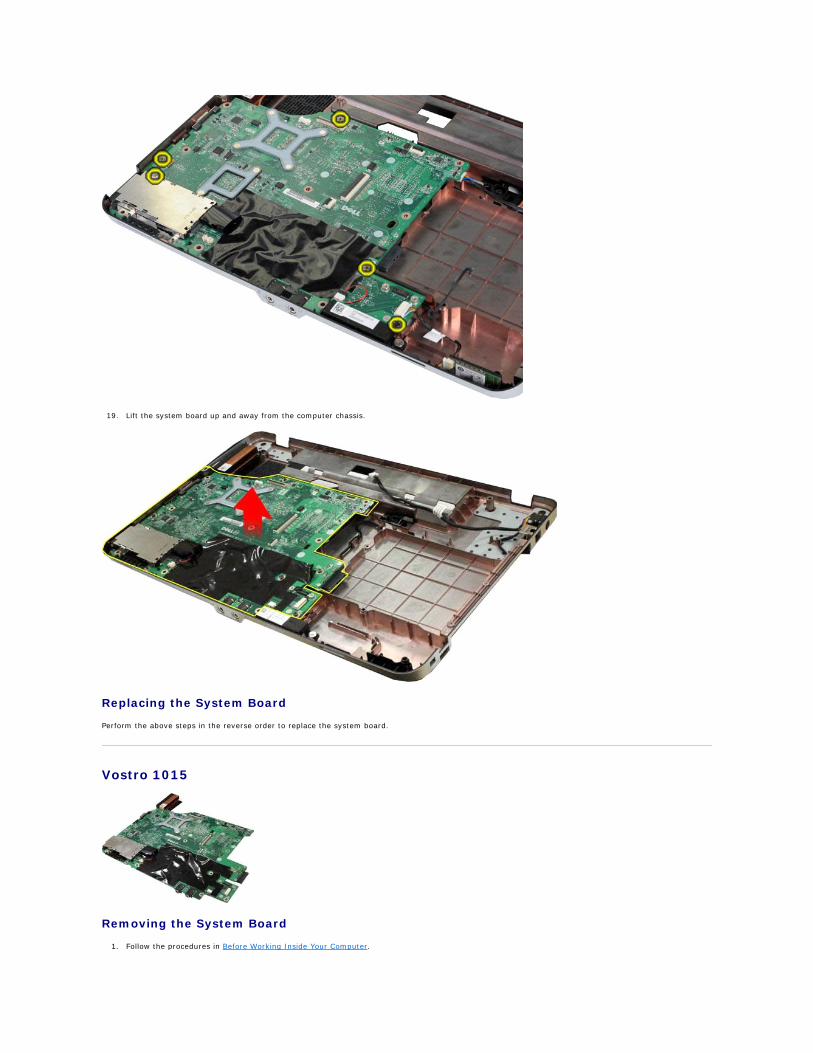
19. Lift the system board up and away from the computer chassis.
Replacing the System Board
Perform the above steps in the reverse order to replace the system board.
Vostro 1015
Removing the System Board
1. Follow the procedures in Before Working Inside Your Computer.
2. Remove the ExpressCard. 3. Remove the memory card. 4. Remove the battery. 5. Remove the access panel. 6. Remove the hard drive. 7. Remove the memory modules. 8. Remove the WLAN card. 9. Remove the control panel cover.
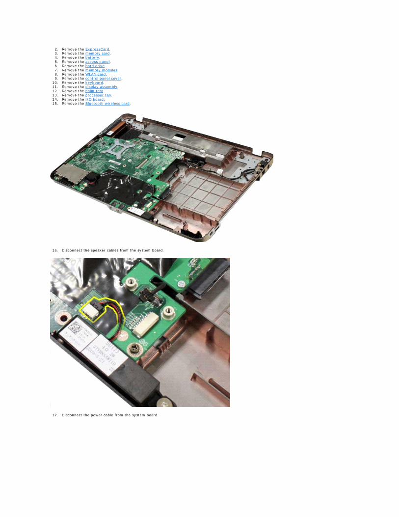
10. Remove the keyboard. 11. Remove the display assembly. 12. Remove the palm rest. 13. Remove the processor fan. 14. Remove the I/O board. 15. Remove the Bluetooth wireless card.
16. Disconnect the speaker cables from the system board.
17. Disconnect the power cable from the system board.
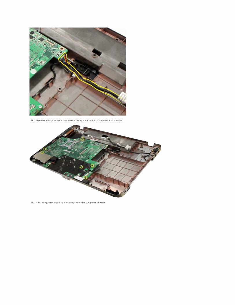
18. Remove the six screws that secure the system board to the computer chassis.
19. Lift the system board up and away from the computer chassis.
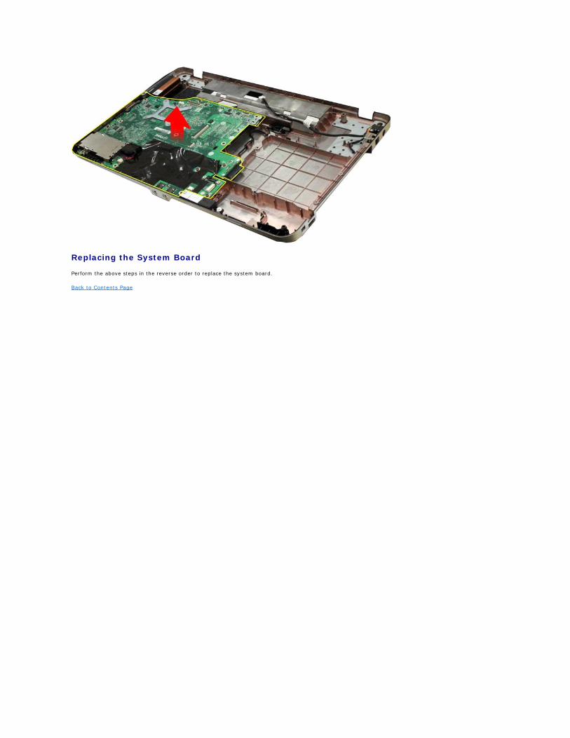
Replacing the System Board
Perform the above steps in the reverse order to replace the system board.
Back to Contents Page
Back to Contents Page
Memory Dell™ Vostro™ 1014/1015 Service Manual
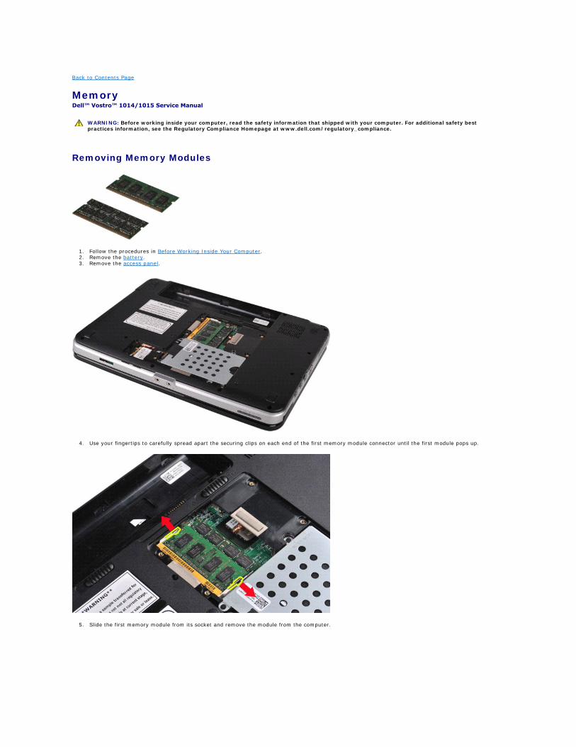
Removing Memory Modules
1. Follow the procedures in Before Working Inside Your Computer. 2. Remove the battery. 3. Remove the access panel.
4. Use your fingertips to carefully spread apart the securing clips on each end of the first memory module connector until the first module pops up.
5. Slide the first memory module from its socket and remove the module from the computer.
WARNING: Before working inside your computer, read the safety information that shipped with your computer. For additional safety best practices information, see the Regulatory Compliance Homepage at www.dell.com/regulatory_compliance.
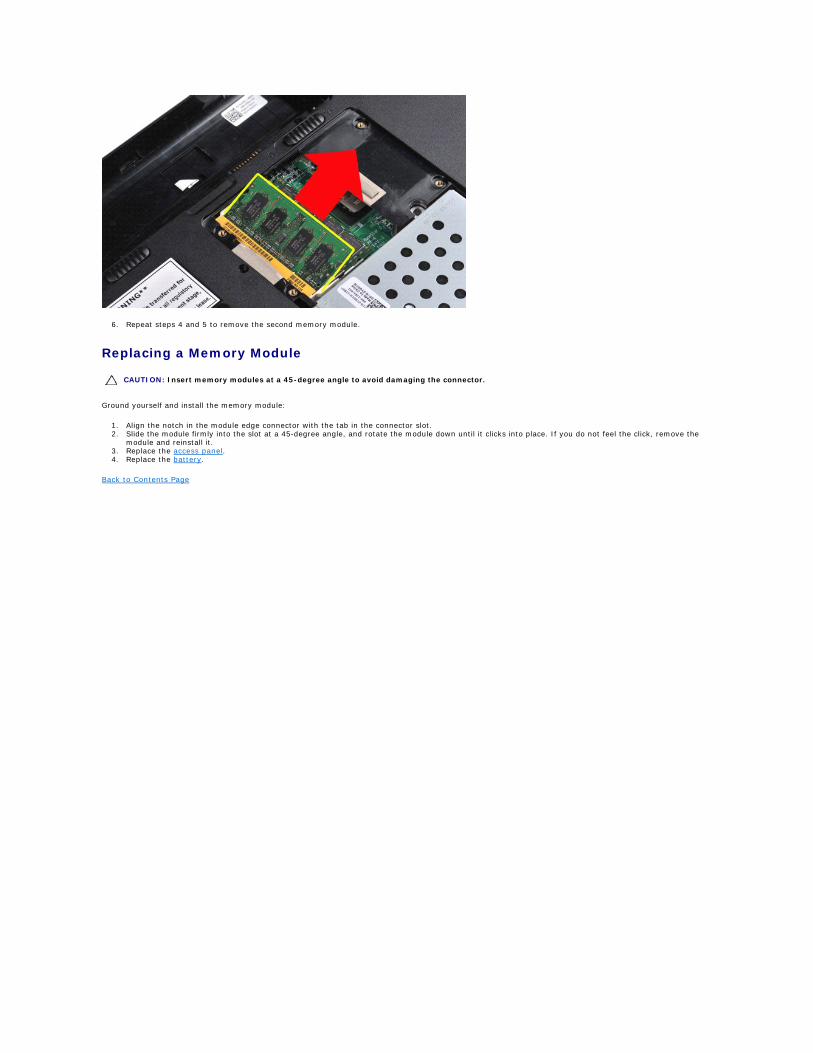
6. Repeat steps 4 and 5 to remove the second memory module.
Replacing a Memory Module
Ground yourself and install the memory module:
1. Align the notch in the module edge connector with the tab in the connector slot. 2. Slide the module firmly into the slot at a 45-degree angle, and rotate the module down until it clicks into place. If you do not feel the click, remove the
module and reinstall it. 3. Replace the access panel. 4. Replace the battery.
Back to Contents Page
CAUTION: Insert memory modules at a 45-degree angle to avoid damaging the connector.
Back to Contents Page
Memory Card Dell™ Vostro™ 1014/1015 Service Manual
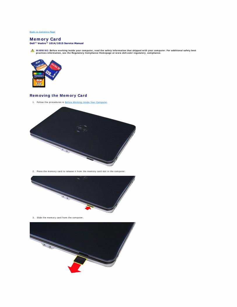
Removing the Memory Card
1. Follow the procedures in Before Working Inside Your Computer.
2. Press the memory card to release it from the memory card slot in the computer.
3. Slide the memory card from the computer.
WARNING: Before working inside your computer, read the safety information that shipped with your computer. For additional safety best practices information, see the Regulatory Compliance Homepage at www.dell.com/regulatory_compliance.

Replacing the Memory Card
Perform the above steps in the reverse to replace a memory card.
Back to Contents Page
Back to Contents Page
Optical Drive Dell™ Vostro™ 1014/1015 Service Manual
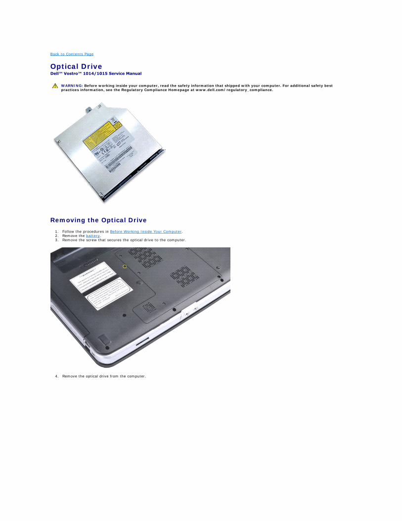
Removing the Optical Drive
1. Follow the procedures in Before Working Inside Your Computer. 2. Remove the battery. 3. Remove the screw that secures the optical drive to the computer.
4. Remove the optical drive from the computer.
WARNING: Before working inside your computer, read the safety information that shipped with your computer. For additional safety best practices information, see the Regulatory Compliance Homepage at www.dell.com/regulatory_compliance.
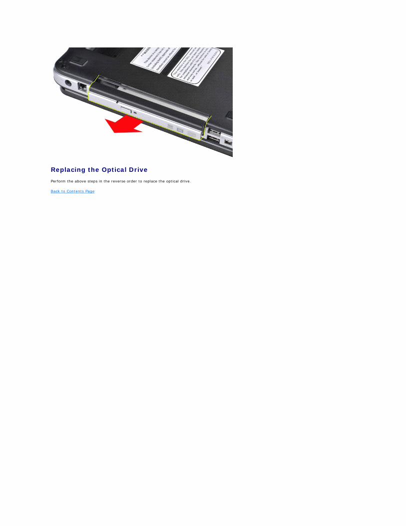
Replacing the Optical Drive
Perform the above steps in the reverse order to replace the optical drive.
Back to Contents Page
Back to Contents Page
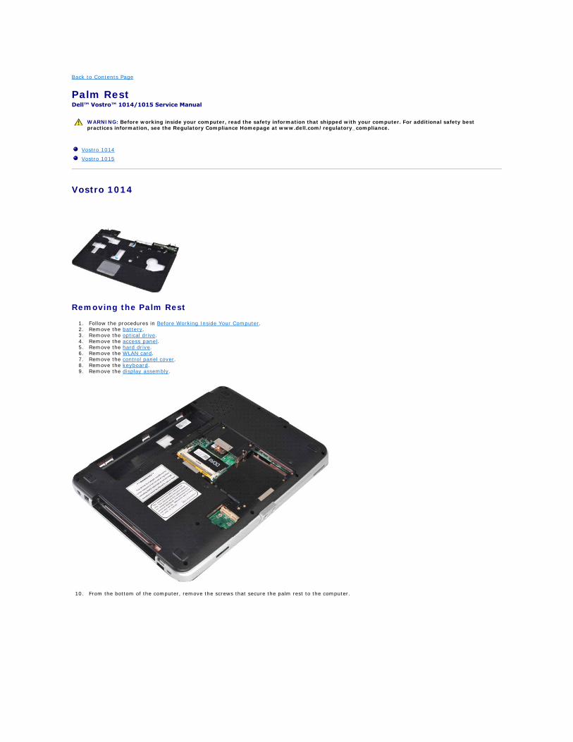
Palm Rest Dell™ Vostro™ 1014/1015 Service Manual
Vostro 1014
Removing the Palm Rest
1. Follow the procedures in Before Working Inside Your Computer. 2. Remove the battery. 3. Remove the optical drive. 4. Remove the access panel. 5. Remove the hard drive. 6. Remove the WLAN card. 7. Remove the control panel cover. 8. Remove the keyboard. 9. Remove the display assembly.
10. From the bottom of the computer, remove the screws that secure the palm rest to the computer.
WARNING: Before working inside your computer, read the safety information that shipped with your computer. For additional safety best practices information, see the Regulatory Compliance Homepage at www.dell.com/regulatory_compliance.
Vostro 1014
Vostro 1015
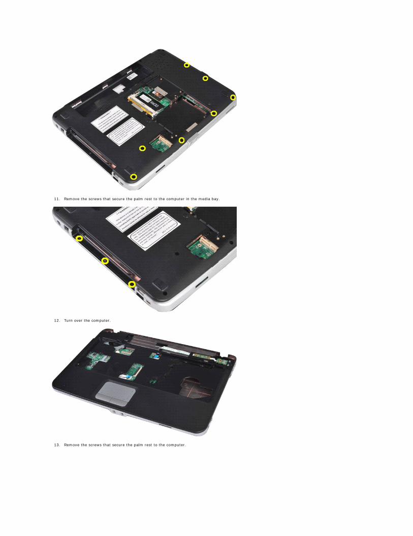
11. Remove the screws that secure the palm rest to the computer in the media bay.
12. Turn over the computer.
13. Remove the screws that secure the palm rest to the computer.
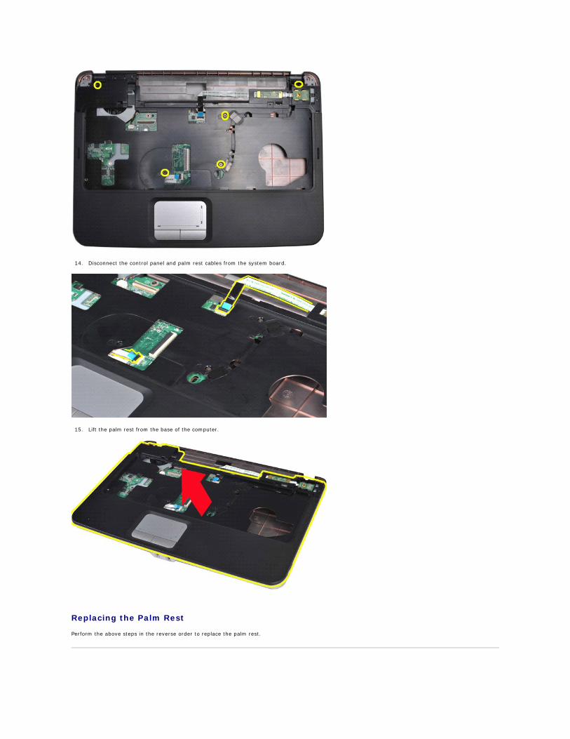
14. Disconnect the control panel and palm rest cables from the system board.
15. Lift the palm rest from the base of the computer.
Replacing the Palm Rest
Perform the above steps in the reverse order to replace the palm rest.
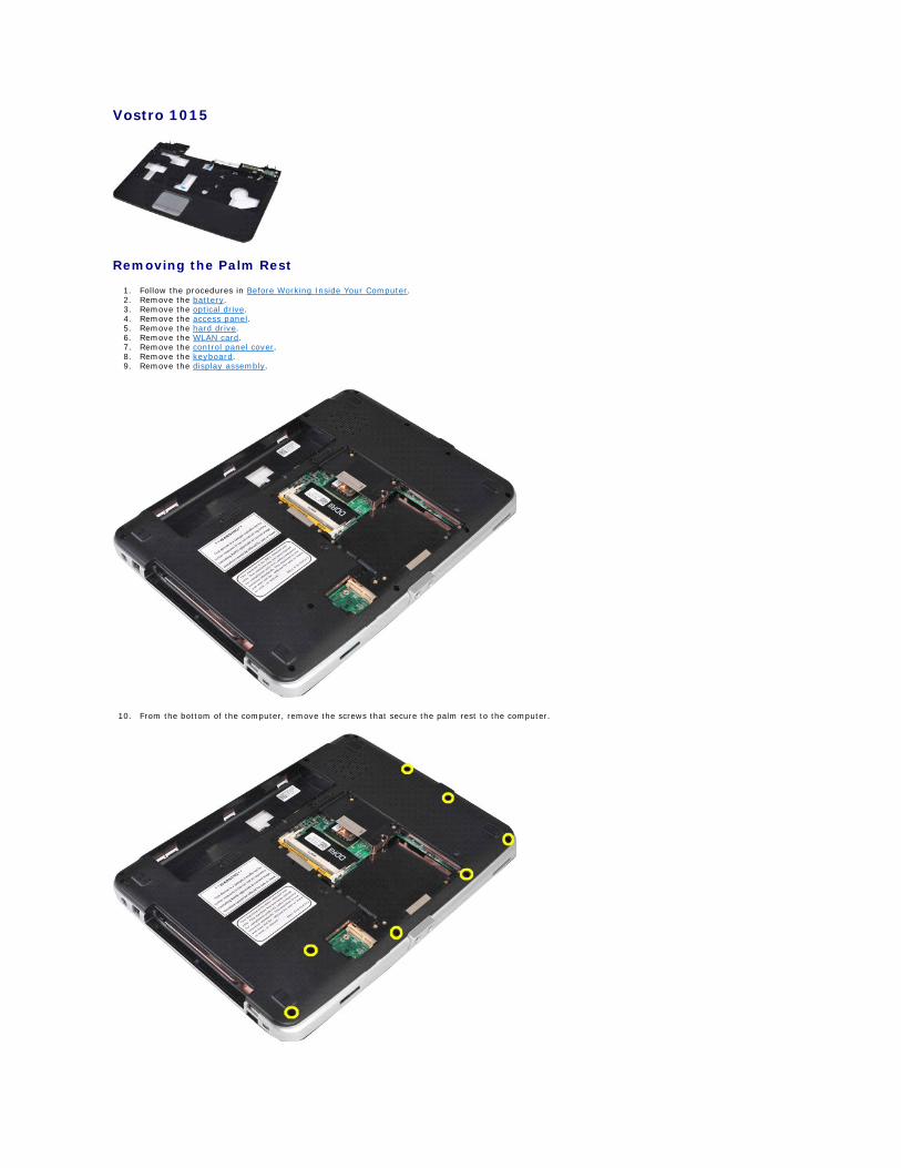
Vostro 1015
Removing the Palm Rest
1. Follow the procedures in Before Working Inside Your Computer. 2. Remove the battery. 3. Remove the optical drive. 4. Remove the access panel. 5. Remove the hard drive. 6. Remove the WLAN card. 7. Remove the control panel cover. 8. Remove the keyboard. 9. Remove the display assembly.
10. From the bottom of the computer, remove the screws that secure the palm rest to the computer.
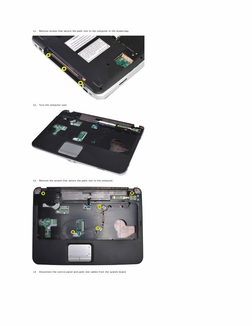
11. Remove screws that secure the palm rest to the computer in the media bay.
12. Turn the computer over.
13. Remove the screws that secure the palm rest to the computer.
14. Disconnect the control panel and palm rest cables from the system board.
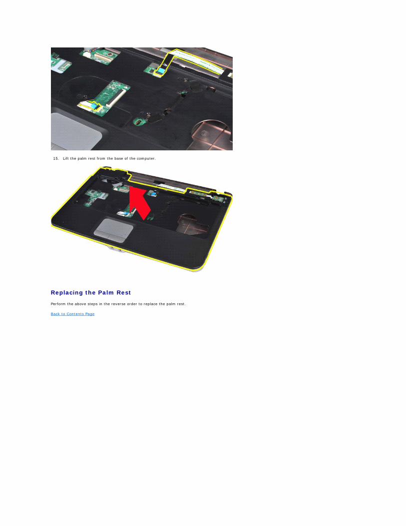
15. Lift the palm rest from the base of the computer.
Replacing the Palm Rest
Perform the above steps in the reverse order to replace the palm rest.
Back to Contents Page
Back to Contents Page
Processor Module Dell™ Vostro™ 1014/1015 Service Manual
Removing the Processor Module
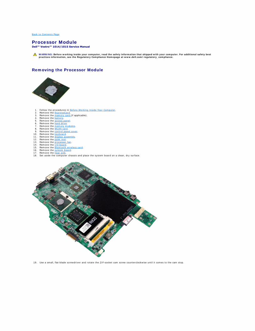
1. Follow the procedures in Before Working Inside Your Computer. 2. Remove the ExpressCard. 3. Remove the memory card (if applicable). 4. Remove the battery. 5. Remove the access panel. 6. Remove the hard drive. 7. Remove the memory modules. 8. Remove the WLAN card. 9. Remove the control panel cover.
10. Remove the keyboard. 11. Remove the display assembly. 12. Remove the palm rest. 13. Remove the processor fan. 14. Remove the I/O board. 15. Remove the Bluetooth wireless card. 16. Remove the system board. 17. Remove the heat sink. 18. Set aside the computer chassis and place the system board on a clean, dry surface.
19. Use a small, flat-blade screwdriver and rotate the ZIF-socket cam screw counterclockwise until it comes to the cam stop.
WARNING: Before working inside your computer, read the safety information that shipped with your computer. For additional safety best practices information, see the Regulatory Compliance Homepage at www.dell.com/regulatory_compliance.
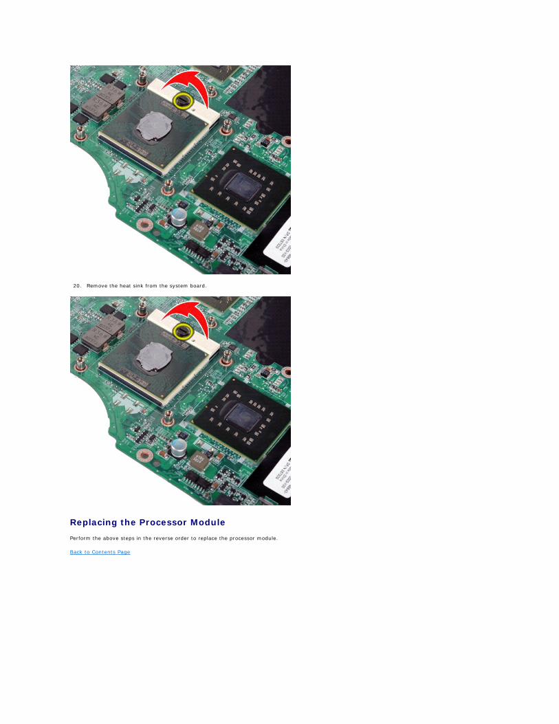
20. Remove the heat sink from the system board.
Replacing the Processor Module
Perform the above steps in the reverse order to replace the processor module.
Back to Contents Page
Back to Contents Page
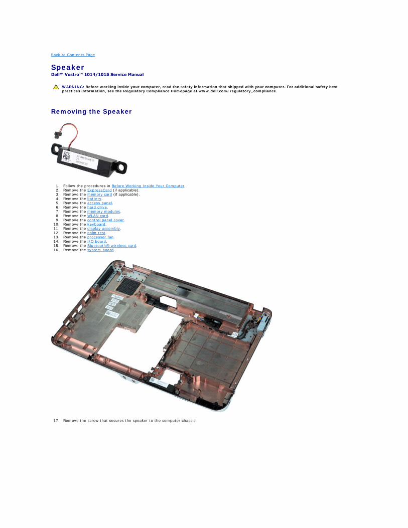
Speaker Dell™ Vostro™ 1014/1015 Service Manual
Removing the Speaker
1. Follow the procedures in Before Working Inside Your Computer. 2. Remove the ExpressCard (if applicable). 3. Remove the memory card (if applicable). 4. Remove the battery. 5. Remove the access panel. 6. Remove the hard drive. 7. Remove the memory modules. 8. Remove the WLAN card. 9. Remove the control panel cover.
10. Remove the keyboard. 11. Remove the display assembly. 12. Remove the palm rest. 13. Remove the processor fan. 14. Remove the I/O board. 15. Remove the Bluetooth® wireless card. 16. Remove the system board.
17. Remove the screw that secures the speaker to the computer chassis.
WARNING: Before working inside your computer, read the safety information that shipped with your computer. For additional safety best practices information, see the Regulatory Compliance Homepage at www.dell.com/regulatory_compliance.
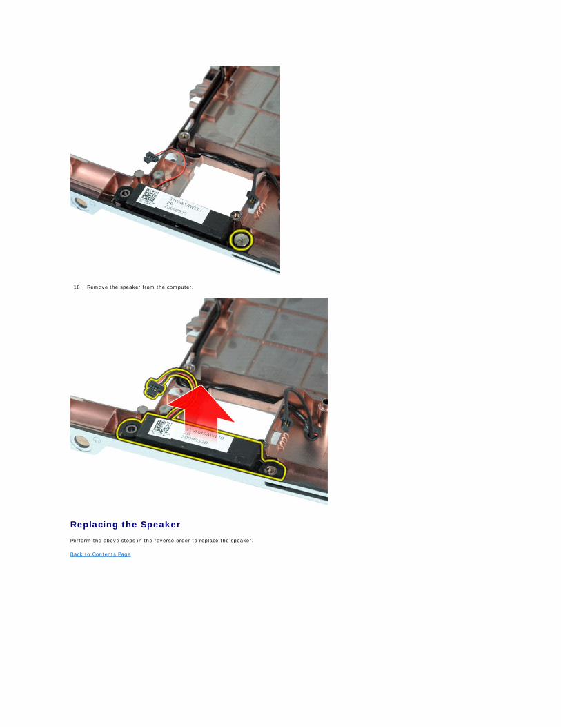
18. Remove the speaker from the computer.
Replacing the Speaker
Perform the above steps in the reverse order to replace the speaker.
Back to Contents Page
Back to Contents Page
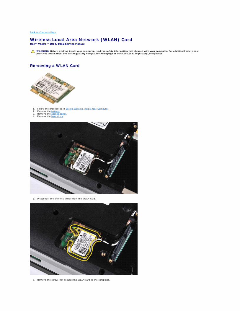
Wireless Local Area Network (WLAN) Card Dell™ Vostro™ 1014/1015 Service Manual
Removing a WLAN Card
1. Follow the procedures in Before Working Inside Your Computer. 2. Remove the battery. 3. Remove the access panel. 4. Remove the hard drive.
5. Disconnect the antenna cables from the WLAN card.
6. Remove the screw that secures the WLAN card to the computer.
WARNING: Before working inside your computer, read the safety information that shipped with your computer. For additional safety best practices information, see the Regulatory Compliance Homepage at www.dell.com/regulatory_compliance.
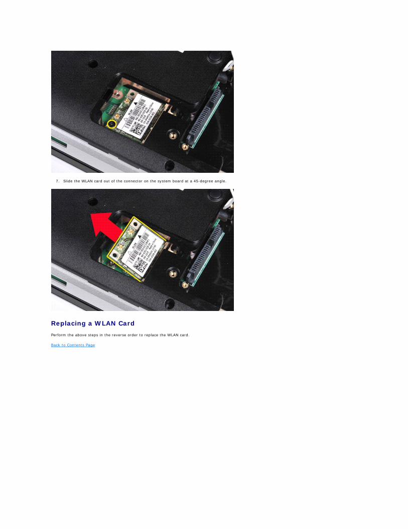
7. Slide the WLAN card out of the connector on the system board at a 45-degree angle.
Replacing a WLAN Card
Perform the above steps in the reverse order to replace the WLAN card.
Back to Contents Page
Back to Contents Page
System Setup Dell™ Vostro™ 1014/1015 Service Manual
Boot Menu
Navigation Keystrokes
Entering System Setup
System Setup Simulation
System Setup Menu Options
Boot Menu
The boot menu allows you to set a one-time boot sequence without entering system setup. You can also use this procedure to run the diagnostics on your
1. Turn on (or restart) your computer. 2. When the Dell™ logo appears, press <F12> immediately. The following options appear:
Internal hard drive CD/DVD/CD-RW Drive Onboard NIC BIOS Setup Diagnostics
3. Select the device from which you want to boot and press <Enter>.
The computer boots to the selected device. The next time you reboot the computer, the previous boot order is restored.
Navigation Keystrokes
Use the following keystrokes to navigate the System Setup screens.
Entering System Setup
You can enter System Setup using one of the following methods:
l Using the boot menu l By pressing <F2>
Boot Menu
1. Turn on (or restart) your computer. 2. When the Dell™ logo appears, press <F12> immediately. 3. Highlight the option to enter System Setup and then press <Enter>
<F2>
1. Turn on (or restart) your computer. 2. When the Dell logo appears, press <F2> immediately.
If you are unable to enter System Setup by pressing the <F2> key when the Dell Logo appears, continue to wait until you see the Windows desktop. Then restart your computer and press <F2> when the keyboard lights first flash.
System Setup Menu Options
The following tables describe the menu options for the System Setup program.
Navigation Keystrokes
Action Keystroke
Expand and collapse field <Enter>, left- or right-arrow key, or +/–
Expand or collapse all fields < >
Exit BIOS <Esc>—Remain in Setup, Save/Exit, Discard/Exit
Change a setting Left or right-arrow key
Select field to change <Enter>
Cancel modification <Esc>
Reset defaults <Alt><F> or Load Defaults menu option
NOTE: Making changes in the boot menu does not make any changes to the boot order stored in the System Setup program.
General
Option Description
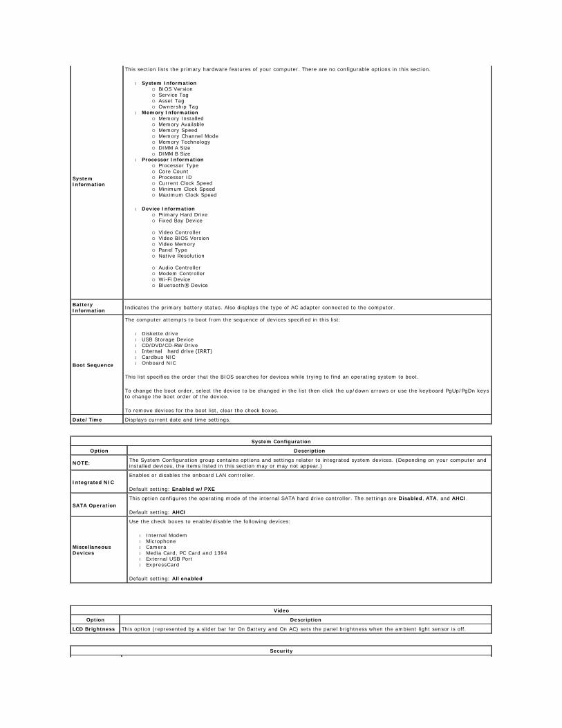
System Information
This section lists the primary hardware features of your computer. There are no configurable options in this section.
l System Information ¡ BIOS Version ¡ Service Tag ¡ Asset Tag ¡ Ownership Tag
l Memory Information ¡ Memory Installed ¡ Memory Available ¡ Memory Speed ¡ Memory Channel Mode ¡ Memory Technology ¡ DIMM A Size ¡ DIMM B Size
l Processor Information ¡ Processor Type ¡ Core Count ¡ Processor ID ¡ Current Clock Speed ¡ Minimum Clock Speed ¡ Maximum Clock Speed
l Device Information ¡ Primary Hard Drive ¡ Fixed Bay Device
¡ Video Controller ¡ Video BIOS Version ¡ Video Memory ¡ Panel Type ¡ Native Resolution
¡ Audio Controller ¡ Modem Controller ¡ Wi-Fi Device ¡ Bluetooth® Device
Battery Information
Indicates the primary battery status. Also displays the type of AC adapter connected to the computer.
Boot Sequence
The computer attempts to boot from the sequence of devices specified in this list:
l Diskette drive l USB Storage Device l CD/DVD/CD-RW Drive l Internal hard drive (IRRT) l Cardbus NIC l Onboard NIC
This list specifies the order that the BIOS searches for devices while trying to find an operating system to boot.
To change the boot order, select the device to be changed in the list then click the up/down arrows or use the keyboard PgUp/PgDn keys to change the boot order of the device.
To remove devices for the boot list, clear the check boxes.
Date/Time Displays current date and time settings.
System Configuration
Option Description
NOTE:The System Configuration group contains options and settings relater to integrated system devices. (Depending on your computer and installed devices, the items listed in this section may or may not appear.)
Integrated NIC
Enables or disables the onboard LAN controller.
Default setting: Enabled w/PXE
SATA Operation
This option configures the operating mode of the internal SATA hard drive controller. The settings are Disabled, ATA, and AHCI.
Default setting: AHCI
Miscellaneous Devices
Use the check boxes to enable/disable the following devices:
l Internal Modem l Microphone l Camera l Media Card, PC Card and 1394 l External USB Port l ExpressCard
Default setting: All enabled
Video
Option Description
LCD Brightness This option (represented by a slider bar for On Battery and On AC) sets the panel brightness when the ambient light sensor is off.
Security
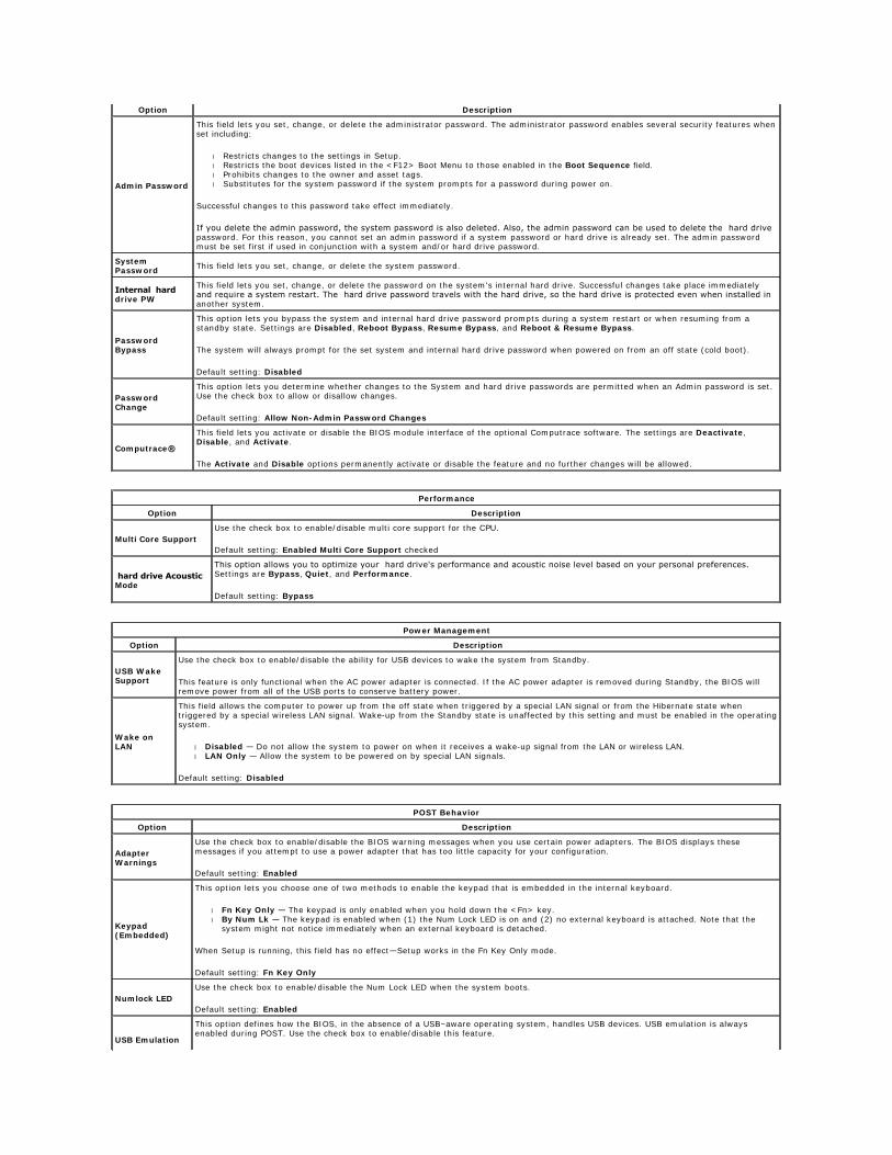
Option Description
Admin Password
This field lets you set, change, or delete the administrator password. The administrator password enables several security features when set including:
l Restricts changes to the settings in Setup. l Restricts the boot devices listed in the <F12> Boot Menu to those enabled in the Boot Sequence field. l Prohibits changes to the owner and asset tags. l Substitutes for the system password if the system prompts for a password during power on.
Successful changes to this password take effect immediately.
If you delete the admin password, the system password is also deleted. Also, the admin password can be used to delete the hard drive password. For this reason, you cannot set an admin password if a system password or hard drive is already set. The admin password must be set first if used in conjunction with a system and/or hard drive password.
System Password
This field lets you set, change, or delete the system password.
Internal hard drive PW
This field lets you set, change, or delete the password on the system's internal hard drive. Successful changes take place immediately and require a system restart. The hard drive password travels with the hard drive, so the hard drive is protected even when installed in another system.
Password Bypass
This option lets you bypass the system and internal hard drive password prompts during a system restart or when resuming from a standby state. Settings are Disabled, Reboot Bypass, Resume Bypass, and Reboot & Resume Bypass.
The system will always prompt for the set system and internal hard drive password when powered on from an off state (cold boot).
Default setting: Disabled
Password Change
This option lets you determine whether changes to the System and hard drive passwords are permitted when an Admin password is set. Use the check box to allow or disallow changes.
Default setting: Allow Non-Admin Password Changes
Computrace®
This field lets you activate or disable the BIOS module interface of the optional Computrace software. The settings are Deactivate, Disable, and Activate.
The Activate and Disable options permanently activate or disable the feature and no further changes will be allowed.
Performance
Option Description
Multi Core Support
Use the check box to enable/disable multi core support for the CPU.
Default setting: Enabled Multi Core Support checked
hard drive Acoustic Mode
This option allows you to optimize your hard drive's performance and acoustic noise level based on your personal preferences. Settings are Bypass, Quiet, and Performance.
Default setting: Bypass
Power Management
Option Description
USB Wake Support
Use the check box to enable/disable the ability for USB devices to wake the system from Standby.
This feature is only functional when the AC power adapter is connected. If the AC power adapter is removed during Standby, the BIOS will remove power from all of the USB ports to conserve battery power.
Wake on LAN
This field allows the computer to power up from the off state when triggered by a special LAN signal or from the Hibernate state when triggered by a special wireless LAN signal. Wake-up from the Standby state is unaffected by this setting and must be enabled in the operating system.
l Disabled — Do not allow the system to power on when it receives a wake-up signal from the LAN or wireless LAN. l LAN Only — Allow the system to be powered on by special LAN signals.
Default setting: Disabled
POST Behavior
Option Description
Adapter Warnings
Use the check box to enable/disable the BIOS warning messages when you use certain power adapters. The BIOS displays these messages if you attempt to use a power adapter that has too little capacity for your configuration.
Default setting: Enabled
Keypad (Embedded)
This option lets you choose one of two methods to enable the keypad that is embedded in the internal keyboard.
l Fn Key Only — The keypad is only enabled when you hold down the <Fn> key. l By Num Lk — The keypad is enabled when (1) the Num Lock LED is on and (2) no external keyboard is attached. Note that the
system might not notice immediately when an external keyboard is detached.
When Setup is running, this field has no effect—Setup works in the Fn Key Only mode.
Default setting: Fn Key Only
Numlock LED
Use the check box to enable/disable the Num Lock LED when the system boots.
Default setting: Enabled
USB Emulation
This option defines how the BIOS, in the absence of a USB–aware operating system, handles USB devices. USB emulation is always enabled during POST. Use the check box to enable/disable this feature.
Back to Contents Page
Default setting: Enabled
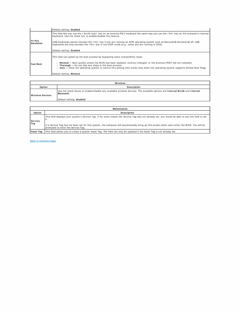
Fn Key Emulation
This field lets you use the <Scroll Lock> key on an external PS/2 keyboard the same way you use the <Fn> key on the computer's internal keyboard. Use the check box to enable/disable this feature.
USB keyboards cannot emulate the <Fn> key if you are running an ACPI operating system such as Microsoft® Windows® XP. USB keyboards will only emulate the <Fn> key in non-ACPI mode (e.g., when you are running in DOS).
Default setting: Enabled
Fast Boot
This field can speed up the boot process by bypassing some compatibility steps.
l Minimal — Boot quickly unless the BIOS has been updated, memory changed, or the previous POST did not complete. l Thorough — Do not skip any steps in the boot process. l Auto — Allow the operating system to control this setting (this works only when the operating system supports Simple Boot Flag).
Default setting: Minimal
Wireless
Option Description
Wireless Devices
Use the check boxes to enable/disable any available wireless devices. The available options are Internal WLAN and Internal Bluetooth.
Default setting: Enabled
Maintenance
Option Description
Service Tag
This field displays your system's Service Tag. If for some reason the Service Tag was not already set, you would be able to use this field to set it.
If a Service Tag has not been set for this system, the computer will automatically bring up this screen when users enter the BIOS. You will be prompted to enter the Service Tag.
Asset Tag This field allows you to create a system Asset Tag. The field can only be updated if the Asset Tag is not already set.
Back to Contents Page
Diagnostics Dell™ Vostro™ 1014/1015 Service Manual
Device Status Lights
Battery Status Lights
Battery Charge and Health
Keyboard Status Lights
LED Error Codes
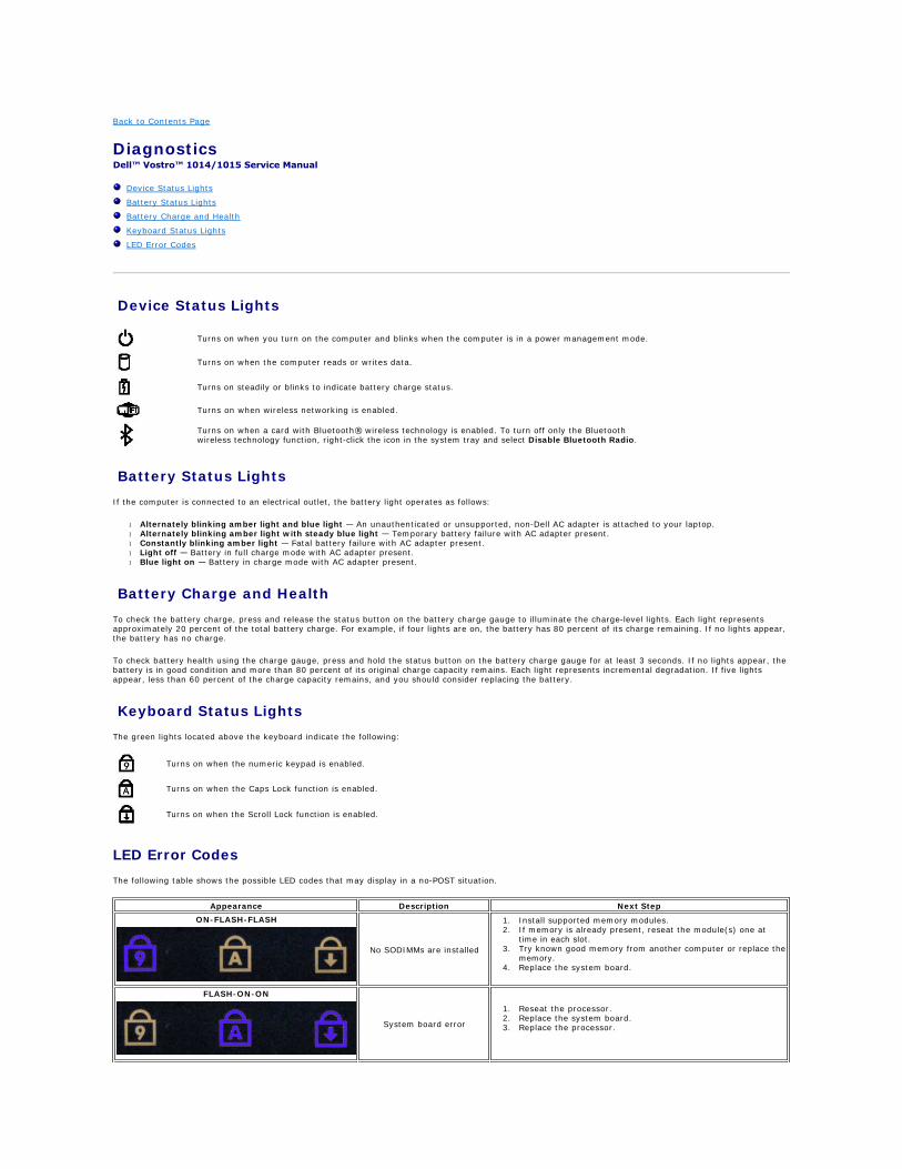
Device Status Lights
Battery Status Lights
If the computer is connected to an electrical outlet, the battery light operates as follows:
l Alternately blinking amber light and blue light — An unauthenticated or unsupported, non-Dell AC adapter is attached to your laptop. l Alternately blinking amber light with steady blue light — Temporary battery failure with AC adapter present. l Constantly blinking amber light — Fatal battery failure with AC adapter present. l Light off — Battery in full charge mode with AC adapter present. l Blue light on — Battery in charge mode with AC adapter present.
Battery Charge and Health
To check the battery charge, press and release the status button on the battery charge gauge to illuminate the charge-level lights. Each light represents approximately 20 percent of the total battery charge. For example, if four lights are on, the battery has 80 percent of its charge remaining. If no lights appear, the battery has no charge.
To check battery health using the charge gauge, press and hold the status button on the battery charge gauge for at least 3 seconds. If no lights appear, the battery is in good condition and more than 80 percent of its original charge capacity remains. Each light represents incremental degradation. If five lights appear, less than 60 percent of the charge capacity remains, and you should consider replacing the battery.
Keyboard Status Lights
The green lights located above the keyboard indicate the following:
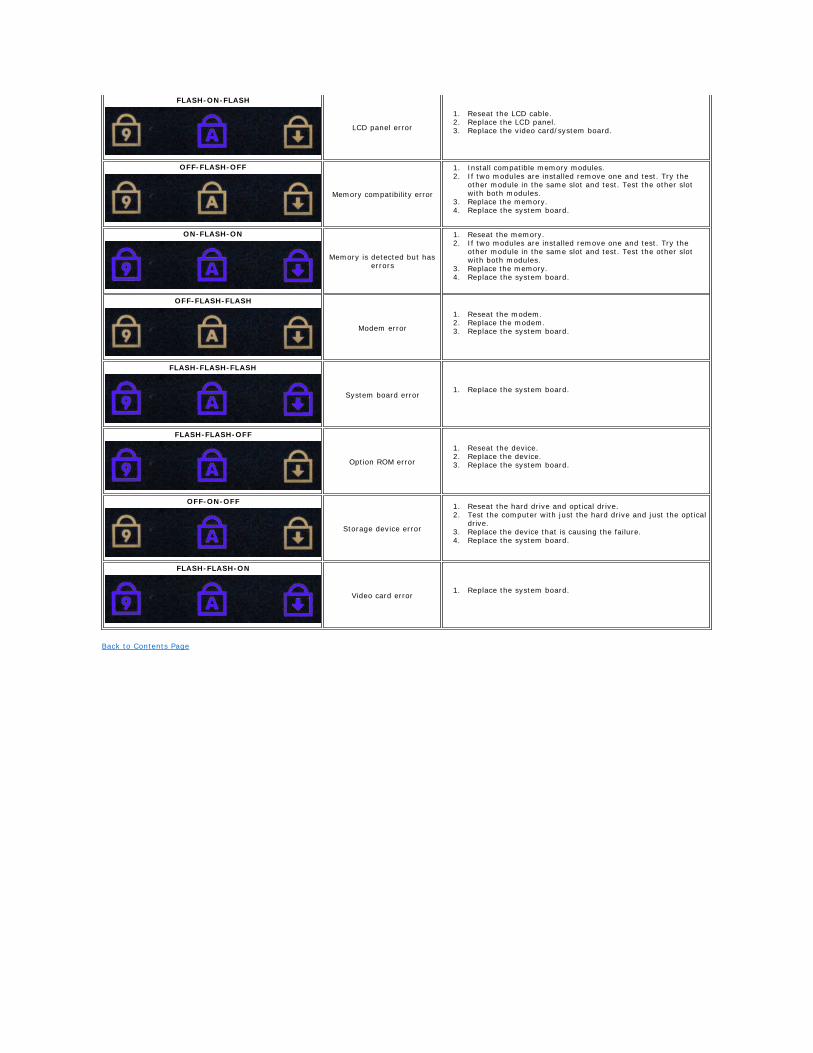
LED Error Codes
The following table shows the possible LED codes that may display in a no-POST situation.
Turns on when you turn on the computer and blinks when the computer is in a power management mode.
Turns on when the computer reads or writes data.
Turns on steadily or blinks to indicate battery charge status.
Turns on when wireless networking is enabled.
Turns on when a card with Bluetooth® wireless technology is enabled. To turn off only the Bluetooth wireless technology function, right-click the icon in the system tray and select Disable Bluetooth Radio.
Turns on when the numeric keypad is enabled.
Turns on when the Caps Lock function is enabled.
Turns on when the Scroll Lock function is enabled.
Appearance Description Next Step
ON-FLASH-FLASH
No SODIMMs are installed
1. Install supported memory modules. 2. If memory is already present, reseat the module(s) one at
time in each slot. 3. Try known good memory from another computer or replace the
memory. 4. Replace the system board.
FLASH-ON-ON
System board error
1. Reseat the processor. 2. Replace the system board. 3. Replace the processor.
Back to Contents Page
FLASH-ON-FLASH
LCD panel error
1. Reseat the LCD cable. 2. Replace the LCD panel. 3. Replace the video card/system board.
OFF-FLASH-OFF
Memory compatibility error
1. Install compatible memory modules. 2. If two modules are installed remove one and test. Try the
other module in the same slot and test. Test the other slot with both modules.
3. Replace the memory. 4. Replace the system board.
ON-FLASH-ON
Memory is detected but has errors
1. Reseat the memory. 2. If two modules are installed remove one and test. Try the
other module in the same slot and test. Test the other slot with both modules.
3. Replace the memory. 4. Replace the system board.
OFF-FLASH-FLASH
Modem error
1. Reseat the modem. 2. Replace the modem. 3. Replace the system board.
FLASH-FLASH-FLASH
System board error1. Replace the system board.
FLASH-FLASH-OFF
Option ROM error
1. Reseat the device. 2. Replace the device. 3. Replace the system board.
OFF-ON-OFF
Storage device error
1. Reseat the hard drive and optical drive. 2. Test the computer with just the hard drive and just the optical
drive. 3. Replace the device that is causing the failure. 4. Replace the system board.
FLASH-FLASH-ON
Video card error1. Replace the system board.
Back to Contents Page
Adding and Replacing Parts Dell™ Vostro™ 1014/1015 Service Manual
Back to Contents Page
ExpressCard
Battery
Access Panel
Memory
Control Panel Cover
Display Assembly
Processor Fan
I/O Board
System Board
Heat Sink
Memory Card
Optical Drive
Hard Drive
WLAN Card
Keyboard
Palm Rest
Coin-Cell Battery
Internal Card with Bluetooth® Wireless Technology
Speaker
Processor
Back to Contents Page
Specifications Dell™ Vostro™ 1014/1015 Service Manual
System Information
Memory
Audio
Battery
5-in-1 Memory Card Reader
Display
Camera (Optional)
Physical
Processor
Communications
Keyboard
Ports and Connectors
Video
Touch Pad
AC Adapter
Environmental
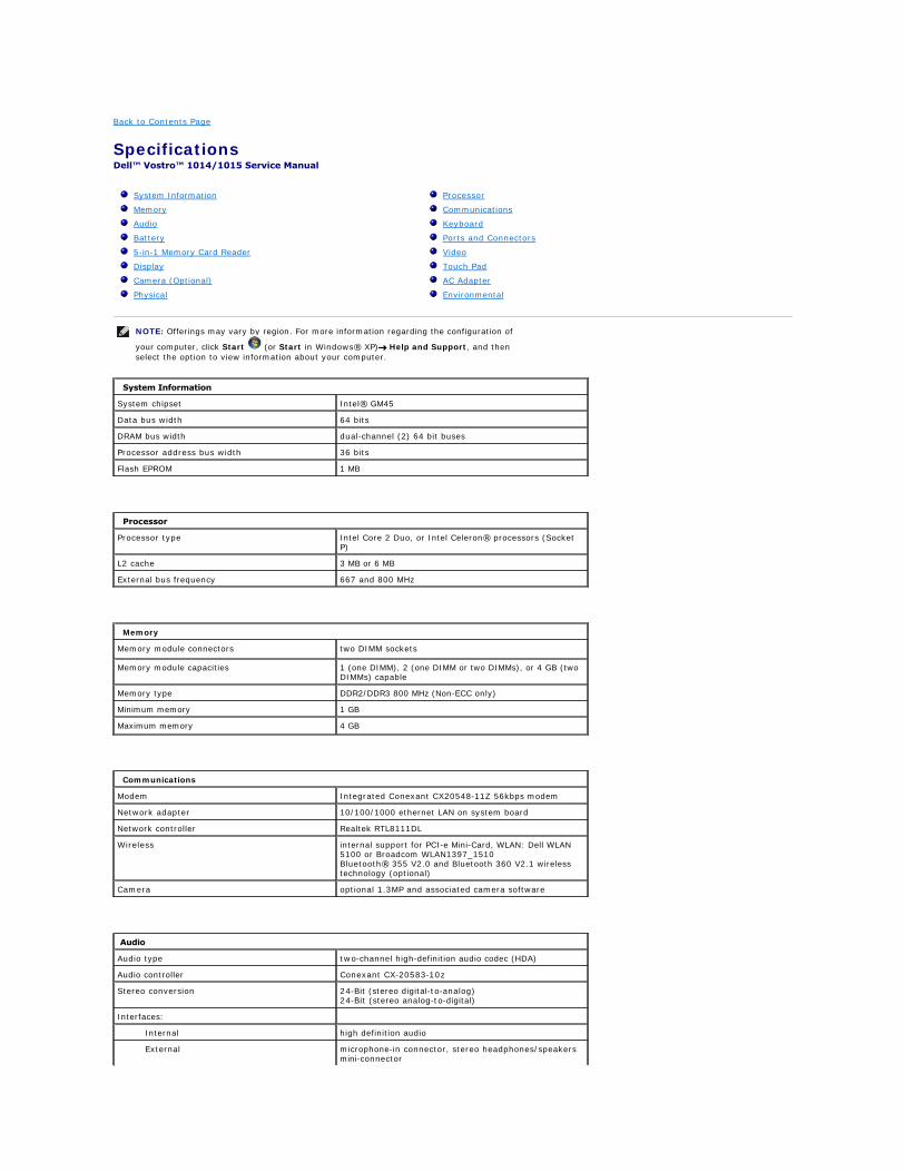
NOTE: Offerings may vary by region. For more information regarding the configuration of
your computer, click Start (or Start in Windows® XP)® Help and Support, and then
select the option to view information about your computer.
System Information
System chipset Intel® GM45
Data bus width 64 bits
DRAM bus width dual-channel (2) 64 bit buses
Processor address bus width 36 bits
Flash EPROM 1 MB
Processor
Processor type Intel Core 2 Duo, or Intel Celeron® processors (Socket P)
L2 cache 3 MB or 6 MB
External bus frequency 667 and 800 MHz
Memory
Memory module connectors two DIMM sockets
Memory module capacities 1 (one DIMM), 2 (one DIMM or two DIMMs), or 4 GB (two DIMMs) capable
Memory type DDR2/DDR3 800 MHz (Non-ECC only)
Minimum memory 1 GB
Maximum memory 4 GB
Communications
Modem Integrated Conexant CX20548-11Z 56kbps modem
Network adapter 10/100/1000 ethernet LAN on system board
Network controller Realtek RTL8111DL
Wireless internal support for PCI-e Mini-Card, WLAN: Dell WLAN 5100 or Broadcom WLAN1397_1510 Bluetooth® 355 V2.0 and Bluetooth 360 V2.1 wireless technology (optional)
Camera optional 1.3MP and associated camera software
Audio
Audio type two-channel high-definition audio codec (HDA)
Audio controller Conexant CX-20583-10z
Stereo conversion 24-Bit (stereo digital-to-analog) 24-Bit (stereo analog-to-digital)
Interfaces:
Internal high definition audio
External microphone-in connector, stereo headphones/speakers mini-connector
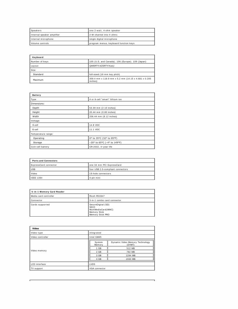
Speakers one 2-watt, 4-ohm speaker
Internal speaker amplifier 2-W channel into 4 ohms
Internal microphone single digital microphone
Volume controls program menus, keyboard function keys
Keyboard
Number of keys 105 (U.S. and Canada); 106 (Europe); 109 (Japan)
Layout QWERTY/AZERTY/Kanji
Size:
Standard full-sized (19 mm key pitch)
Maximum 359.4 mm x 118.9 mm x 5.2 mm (14.15 x 4.681 x 0.205 inches)
Battery
Type 4 or 6-cell "smart" lithium ion
Dimensions:
Depth 53.39 mm (2.10 inches)
Height 20.44 mm (0.80 inches)
Width 206.44 mm (8.12 inches)
Voltage:
4-cell 14.8 VDC
6-cell 11.1 VDC
Temperature range:
Operating 0° to 35°C (32° to 95°F)
Storage –20° to 65°C (–4° to 149°F)
Coin-cell battery CR-2032, 4–year life
Ports and Connectors
ExpressCard connector one 34 mm PCI ExpressCard
USB four USB 2.0-compliant connectors
Video 15-hole connectors
IEEE 1394 4-pin mini
5-in-1 Memory Card Reader
Media card controller Ricoh R5C847
Connector 3-in-1 combo card connector
Cards supported SecureDigital (SD) SDIO MultiMediaCard(MMC) Memory Stick Memory Stick PRO
Video
Video type integrated
Video controller Intel GM45
Video memory
System Memory
Dynamic Video Memory Technology (DVMT)
1 GB 512 MB
2 GB 782 MB
3 GB 1294 MB
4 GB 1550 MB
LCD interface LVDS
TV support VGA connector
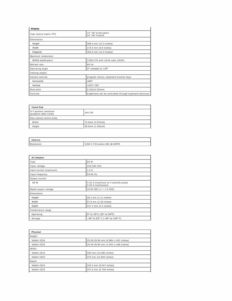
Display
Type (active-matrix TFT)14" HD w/anti-glare 14" HD TrueLife
Dimensions
Height 309.4 mm (12.2 inches)
Width 174.0 mm (6.9 inches)
Diagonal 355.6 mm (14.0 inches)
Maximum resolutions
WXGA w/anti-glare 1280x720 with 18-bit color (262K)
Refresh rate 60 Hz
Operating angle 0° (closed) to 135°
Viewing angles
Volume controls program menus, keyboard function keys
Horizontal ±40°
Vertical ±15°/–30°
Pixel pitch 0.252x0.252mm
Controls brightness can be controlled through keyboard shortcuts
Touch Pad
X/Y position resolution (graphics table mode)
240 CPI
Size (sensor-active area)
Width 75.4mm (2.97inch)
Height 38.0mm (1.50inch)
Camera
Resolution 1280 X 720 pixels (HD) @ 30FPS
AC Adapter
Type 65 W
Input voltage 100-240 VAC
Input current (maximum) 1.5 A
Input frequency 50-60 Hz
Output current
65 W 4.34 A (maximum at 4 seconds pulse) 3.34 A (continuous)
Rated output voltage 19.50 VDC (+/− 1.0 VDC)
Dimensions
Height 28.2 mm (1.11 inches)
Width 57.9 mm (2.28 inches)
Depth 137.2 mm (5.4 inches)
Temperature range
Operating 0° to 35°C (32° to 95°F)
Storage –40° to 65° C (–40° to 149° F)
Physical
Height:
Vostro 1014 25.00-35.60 mm (0.984–1.401 inches)
Vostro 1015 26.50-36.80 mm (1.043–1.448 inches)
Width:
Vostro 1014 340 mm (13.385 inches)
Vostro 1015 376 mm (14.803 inches)
Depth:
Vostro 1014 242.5 mm (9.547 inches)
Vostro 1015 247.9 mm (9.759 inches)
Back to Contents Page
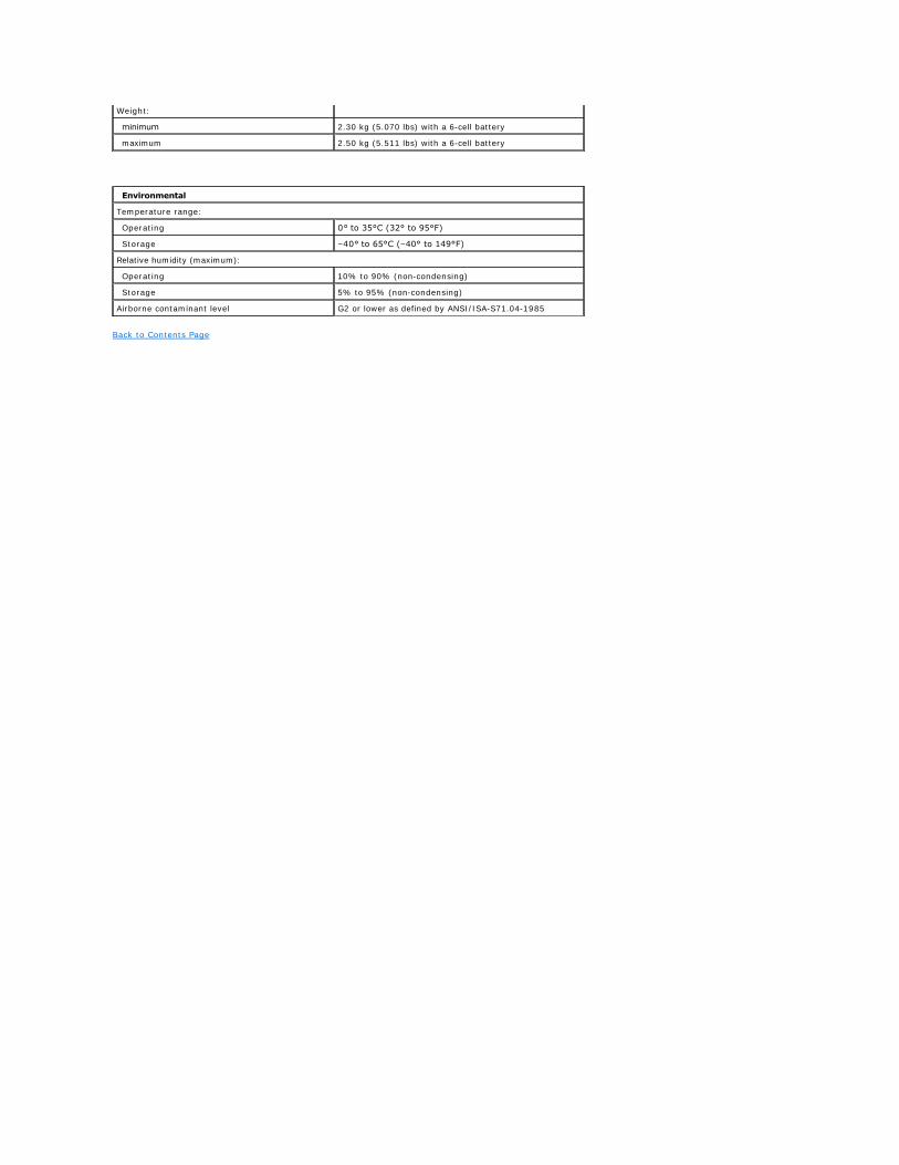
Weight:
minimum 2.30 kg (5.070 lbs) with a 6-cell battery
maximum 2.50 kg (5.511 lbs) with a 6-cell battery
Environmental
Temperature range:
Operating 0° to 35°C (32° to 95°F)
Storage –40° to 65°C (–40° to 149°F)
Relative humidity (maximum):
Operating 10% to 90% (non-condensing)
Storage 5% to 95% (non-condensing)
Airborne contaminant level G2 or lower as defined by ANSI/ISA-S71.04-1985
Working on Your Computer Dell™ Vostro™ 1014/1015 Service Manual
Before Working Inside Your Computer
Use the following safety guidelines to help protect your computer from potential damage and to help to ensure your personal safety. Unless otherwise noted, each procedure included in this document assumes that the following conditions exist:
l You have performed the steps in Working on Your Computer. l You have read the safety information that shipped with your computer. l A component can be replaced or—if purchased separately—installed by performing the removal procedure in reverse order.
To avoid damaging your computer, perform the following steps before you begin working inside the computer.
1. Ensure that your work surface is flat and clean to prevent the computer cover from being scratched. 2. Turn off your computer (see Turning Off Your Computer). 3. If the computer is connected to a docking device (docked), undock it.
4. Disconnect all network cables from the computer. 5. Disconnect your computer and all attached devices from their electrical outlets. 6. Where applicable, disconnect any adapters from the computer. 6. Close the display and turn the computer upside-down on a flat work surface.
7. Remove the main battery (see Battery). 8. Turn the computer top-side up. 9. Open the display.
10. Press the power button to ground the system board.
11. Remove any installed ExpressCards or Smart Cards from the appropriate slots. 12. Remove the hard drive (see Hard Drive).
Recommended Tools
The procedures in this document may require the following tools:
l Small flat-blade screwdriver l #0 Phillips screwdriver l #1 Phillips screwdriver l Small plastic scribe l Flash BIOS update program CD
Turning Off Your Computer
Before Working Inside Your Computer
Recommended Tools
Turning Off Your Computer
After Working Inside Your Computer
WARNING: Before working inside your computer, read the safety information that shipped with your computer. For additional safety best practices information, see the Regulatory Compliance Homepage at www.dell.com/regulatory_compliance.
CAUTION: Many repairs may only be done by a certified service technician. You should only perform troubleshooting and simple repairs as authorized in your product documentation, or as directed by the online or telephone service and support team. Damage due to servicing that is not authorized by Dell is not covered by your warranty. Read and follow the safety instructions that came with the product.
CAUTION: To avoid electrostatic discharge, ground yourself by using a wrist grounding strap or by periodically touching an unpainted metal surface, such as a connector on the back of the computer.
CAUTION: Handle components and cards with care. Do not touch the components or contacts on a card. Hold a card by its edges or by its metal mounting bracket. Hold a component such as a processor by its edges, not by its pins.
CAUTION: When you disconnect a cable, pull on its connector or on its pull-tab, not on the cable itself. Some cables have connectors with locking tabs; if you are disconnecting this type of cable, press in on the locking tabs before you disconnect the cable. As you pull connectors apart, keep them evenly aligned to avoid bending any connector pins. Also, before you connect a cable, ensure that both connectors are correctly oriented and aligned.
NOTE: The color of your computer and certain components may appear differently than shown in this document.
CAUTION: To disconnect a network cable, first unplug the cable from your computer and then unplug the cable from the network device.
CAUTION: To avoid damaging the system board, you must remove the main battery before you service the computer.
CAUTION: To guard against electrical shock, always unplug your computer from the electrical outlet before opening the display.
CAUTION: Before touching anything inside your computer, ground yourself by touching an unpainted metal surface, such as the metal at the back of the computer. While you work, periodically touch an unpainted metal surface to dissipate static electricity, which could harm internal components.
CAUTION: To avoid losing data, save and close all open files and exit all open programs before you turn off your computer.
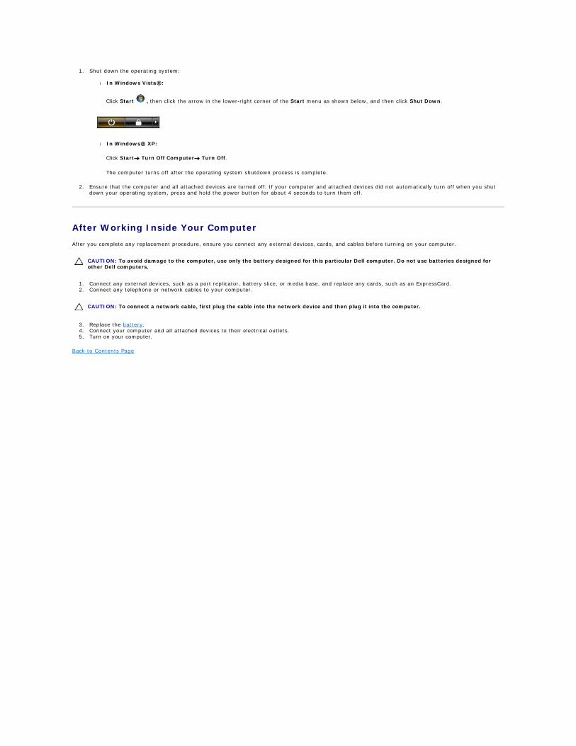
1. Shut down the operating system:
l In Windows Vista®:
Click Start , then click the arrow in the lower-right corner of the Start menu as shown below, and then click Shut Down.
l In Windows® XP:
Click Start® Turn Off Computer® Turn Off.
The computer turns off after the operating system shutdown process is complete.
2. Ensure that the computer and all attached devices are turned off. If your computer and attached devices did not automatically turn off when you shut down your operating system, press and hold the power button for about 4 seconds to turn them off.
After Working Inside Your Computer
After you complete any replacement procedure, ensure you connect any external devices, cards, and cables before turning on your computer.
1. Connect any external devices, such as a port replicator, battery slice, or media base, and replace any cards, such as an ExpressCard. 2. Connect any telephone or network cables to your computer.
3. Replace the battery. 4. Connect your computer and all attached devices to their electrical outlets. 5. Turn on your computer.
Back to Contents Page
CAUTION: To avoid damage to the computer, use only the battery designed for this particular Dell computer. Do not use batteries designed for other Dell computers.
CAUTION: To connect a network cable, first plug the cable into the network device and then plug it into the computer.