Embed Size (px)
Citation preview
Dell™ Vostro™ 1520 Service Manual
Notes, Cautions, and Warnings
If you purchased a Dell™ n Series computer, any references in this document to Microsoft® Windows® operating systems are not applicable.
Information in this document is subject to change without notice. © 2009 Dell Inc. All rights reserved.
Reproduction of this material in any manner whatsoever without the written permission of Dell Inc. is strictly forbidden.
Trademarks used in this text: Dell, the DELL logo, Vostro, TravelLite, Wi-Fi Catcher, and ExpressCharge, are trademarks of Dell Inc.; Intel, Pentium, Celeron and Core are registered trademarks of Intel Corporation; Bluetooth is a registered trademark owned by Bluetooth SIG, Inc. and is used by Dell under license; TouchStrip is a trademark of Zvetco Biometrics, LLC; Blu-ray Disc is a trademark of the Blu-ray Disc Association; Microsoft, Windows, Windows Vista, and the Windows Vista start button are either trademarks or registered trademarks of Microsoft Corporation in the United States and/or other countries.
Other trademarks and trade names may be used in this document to refer to either the entities claiming the marks and names or their products. Dell Inc. disclaims any proprietary interest in trademarks and trade names other than its own.
May 2009 Rev. A00
Working on Your Computer
Adding and Replacing Parts
Specifications
Diagnostics
System Setup
NOTE: A NOTE indicates important information that helps you make better use of your computer.
CAUTION: A CAUTION indicates potential damage to hardware or loss of data if instructions are not followed.
WARNING: A WARNING indicates a potential for property damage, personal injury, or death.
Back to Contents Page
System Setup Dell™ Vostro™ 1520 Service Manual
Entering System Setup
<F12> Menu
Your computer's BIOS, or System Setup program allows you to do the following:
l Access System Setup by pressing <F2> l Bring up a one-time boot menu by pressing <F12>
Entering System Setup
Press <F2> to enter System Setup and make changes to the user-definable settings. If you are having trouble entering Setup using this key, reboot and press the <F2> key when the keyboard LEDs first flash.
<F12> Menu
Press <F12> when the Dell logo appears to initiate a one-time boot menu with a list of the valid boot devices for the computer. The devices listed on the boot menu depend on the bootable devices installed in the computer.
l Internal HDD l CD/DVD/CD-RW Drive l Onboard NIC l BIOS Setup l Diagnostics (starts the Pre-boot System Assessment (PSA) diagnostics)
This menu is useful when attempting to boot to a particular device or to bring up the diagnostics for the computer. Using the boot menu does not make any changes to the boot order stored in the BIOS.
Back to Contents Page
Diagnostics Dell™ Vostro™ 1520 Service Manual
Device Status Lights
LED Error Codes
Power Button Light Codes
Device Status Lights
If your computer is connected to an electrical outlet, the light operates as follows:
l Solid blue—The battery is charging. l Flashing blue—The battery is almost fully charged.
If your computer is running on a battery, the light operates as follows:
l Off—The battery is adequately charged, or the computer is turned off. l Flashing orange—The battery charge is low. l Solid orange—The battery charge is critically low.
LED Error Codes
If your computer does not perform a Power-On Self-Test upon boot up, there are various things to look for:
1. Check that the computer power light is on. 2. If the power light is not on, ensure that your computer is plugged into AC power. Remove the battery. 3. If your computer is powered on but is not performing a POST, check to see whether or not the keyboard status lights flash to indicate a successful POST
but no video or if the keyboard status lights are lit in a sequence indicating a system problem.
The following table shows the possible LED codes that may display in a no-POST situation.
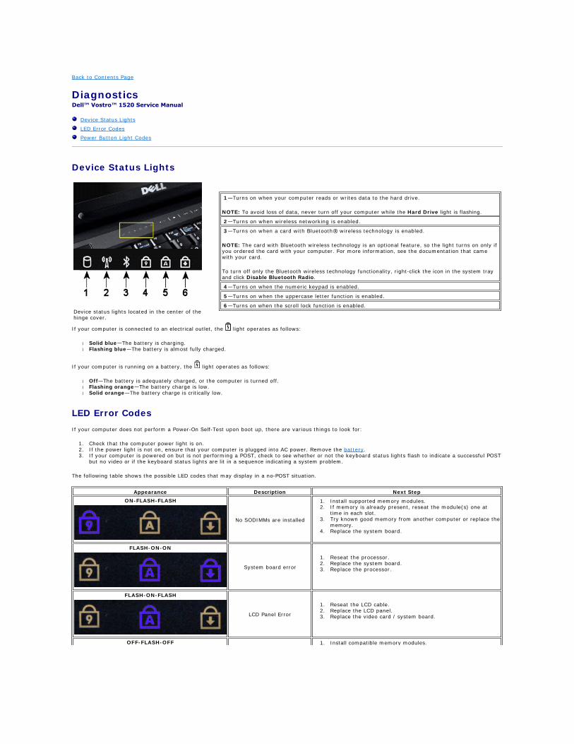
Device status lights located in the center of the hinge cover.
1—Turns on when your computer reads or writes data to the hard drive.
NOTE: To avoid loss of data, never turn off your computer while the Hard Drive light is flashing.
2—Turns on when wireless networking is enabled.
3—Turns on when a card with Bluetooth® wireless technology is enabled.
NOTE: The card with Bluetooth wireless technology is an optional feature, so the light turns on only if you ordered the card with your computer. For more information, see the documentation that came with your card.
To turn off only the Bluetooth wireless technology functionality, right-click the icon in the system tray and click Disable Bluetooth Radio.
4—Turns on when the numeric keypad is enabled.
5—Turns on when the uppercase letter function is enabled.
6—Turns on when the scroll lock function is enabled.
Appearance Description Next Step
ON-FLASH-FLASH
No SODIMMs are installed
1. Install supported memory modules. 2. If memory is already present, reseat the module(s) one at
time in each slot. 3. Try known good memory from another computer or replace the
memory. 4. Replace the system board.
FLASH-ON-ON
System board error
1. Reseat the processor. 2. Replace the system board. 3. Replace the processor.
FLASH-ON-FLASH
LCD Panel Error
1. Reseat the LCD cable. 2. Replace the LCD panel. 3. Replace the video card / system board.
OFF-FLASH-OFF 1. Install compatible memory modules.
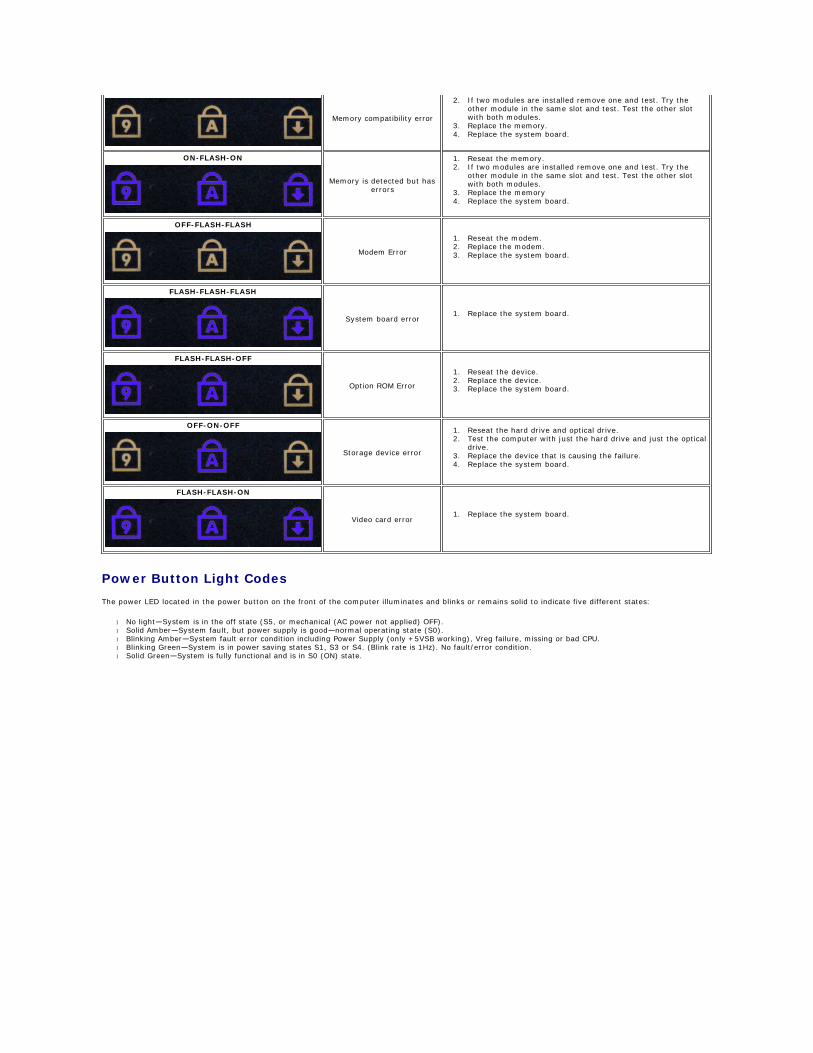
Power Button Light Codes
The power LED located in the power button on the front of the computer illuminates and blinks or remains solid to indicate five different states:
l No light—System is in the off state (S5, or mechanical (AC power not applied) OFF). l Solid Amber—System fault, but power supply is good—normal operating state (S0). l Blinking Amber—System fault error condition including Power Supply (only +5VSB working), Vreg failure, missing or bad CPU. l Blinking Green—System is in power saving states S1, S3 or S4. (Blink rate is 1Hz). No fault/error condition. l Solid Green—System is fully functional and is in S0 (ON) state.
Memory compatibility error
2. If two modules are installed remove one and test. Try the other module in the same slot and test. Test the other slot with both modules.
3. Replace the memory. 4. Replace the system board.
ON-FLASH-ON
Memory is detected but has errors
1. Reseat the memory. 2. If two modules are installed remove one and test. Try the
other module in the same slot and test. Test the other slot with both modules.
3. Replace the memory 4. Replace the system board.
OFF-FLASH-FLASH
Modem Error
1. Reseat the modem. 2. Replace the modem. 3. Replace the system board.
FLASH-FLASH-FLASH
System board error1. Replace the system board.
FLASH-FLASH-OFF
Option ROM Error
1. Reseat the device. 2. Replace the device. 3. Replace the system board.
OFF-ON-OFF
Storage device error
1. Reseat the hard drive and optical drive. 2. Test the computer with just the hard drive and just the optical
drive. 3. Replace the device that is causing the failure. 4. Replace the system board.
FLASH-FLASH-ON
Video card error1. Replace the system board.

Back to Contents Page
Adding and Replacing Parts Dell™ Vostro™ 1520 Service Manual
Battery
Hard Drive
Wireless Local Area Network (WLAN) Card
Optical Drive
Processor and Memory Access Panel
Heat Sink and Processork
Display Assembly
Camera
LCD Display Panel
Keyboard
USB/IEEE 1394 Board
Speaker Assembly
Coin-Cell Battery
Hard Drive and Mini-Card Access Panel
Wireless Wide Area Network (WWAN) Card
Internal Card With Bluetooth® Wireless Technology
Fan
Memory
Hinge Cover
Display Bezel
Display Assembly Hinges
Display Inverter
Palm Rest
Fingerprint Reader
System Board
Back to Contents Page
Specifications Dell™ Vostro™ 1520 Service Manual
Processor
System Information
ExpressCard™
8-in-1 Memory Card Reader
Memory
Connectors
Communications
Video
Audio
Display
Keyboard
Touch Pad
Fingerprint Reader
Camera
Battery
AC Adapter
Physical
Environmental
NOTE: Offerings may vary by region. For more information regarding the configuration of
your Tablet-PC, click Start (or Start in Windows XP)® Help and Support, and then
select the option to view information about your Tablet-PC.
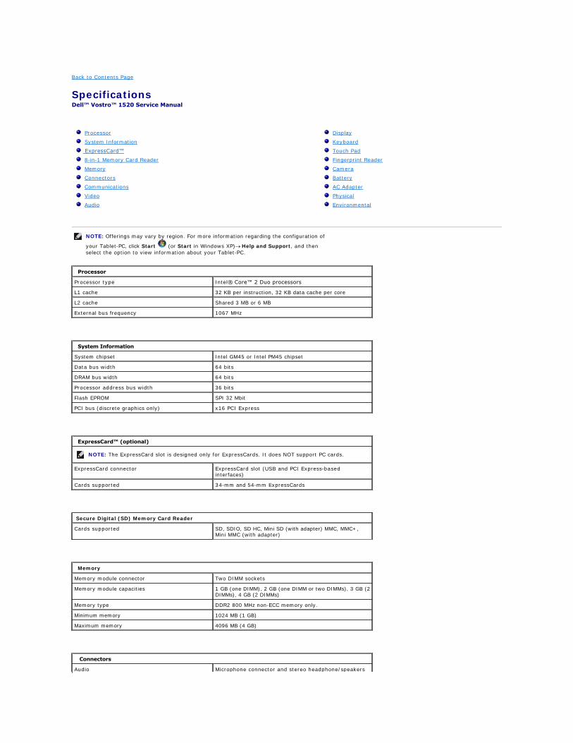
Processor
Processor type Intel® Core™ 2 Duo processors
L1 cache 32 KB per instruction, 32 KB data cache per core
L2 cache Shared 3 MB or 6 MB
External bus frequency 1067 MHz
System Information
System chipset Intel GM45 or Intel PM45 chipset
Data bus width 64 bits
DRAM bus width 64 bits
Processor address bus width 36 bits
Flash EPROM SPI 32 Mbit
PCI bus (discrete graphics only) x16 PCI Express
ExpressCard™ (optional)
NOTE: The ExpressCard slot is designed only for ExpressCards. It does NOT support PC cards.
ExpressCard connector ExpressCard slot (USB and PCI Express-based interfaces)
Cards supported 34-mm and 54-mm ExpressCards
Secure Digital (SD) Memory Card Reader
Cards supported SD, SDIO, SD HC, Mini SD (with adapter) MMC, MMC+, Mini MMC (with adapter)
Memory
Memory module connector Two DIMM sockets
Memory module capacities 1 GB (one DIMM), 2 GB (one DIMM or two DIMMs), 3 GB (2 DIMMs), 4 GB (2 DIMMs)
Memory type DDR2 800 MHz non-ECC memory only.
Minimum memory 1024 MB (1 GB)
Maximum memory 4096 MB (4 GB)
Connectors
Audio Microphone connector and stereo headphone/speakers
connector
IEEE 1394 One 4-pin -connector
Dock Optional USB Port Replicator only
Mini-card support (internal expansion slots) One dedicated half Mini-Card slot for WLAN One dedicated full Mini-Card slot for WPAN (Bluetooth® or ultra wideband [UWB]) WPAN full Mini-Card slot can also be used for the Intel Flash Cache
Modem Optional USB external modem
Network adapter RJ-45 connector
USB, USB PowerShare, eSATA Four 4-pin USB 2.0-compliant connectors
Video VGA
Communications
Modem External (optional)
Network adapter 10/100/1000 Ethernet LAN on system board
Wireless WLAN half Mini-Card, WPAN full Mini-Cards, Bluetooth® wireless support, and UWB technology
Mobile Broadband None
GPS None
Video
Video type Integrated Discrete on system board, hardware accelerated
Video controller Integrated video: Mobile Intel GMA X4500 Discrete video: NVIDIA GeForce 9300M GS
Data bus Integrated video or PCI-Express video x16
Video memory Integrated video: up to 256 MB shared Discrete video: 256 MB dedicated memory
Video output Video connector and multimode DisplayPort
Audio
Audio type Two-channel high-definition audio codec
Audio controller IDT 92HD71B5
Stereo conversion 24-Bit (stereo digital-to-analog) 24-Bit (stereo analog-to-digital)
Interfaces:
Internal Internal High Definition Audio
External Microphone-in connector, stereo headphones/speakers mini-connector
Speaker One 2-watt, 4-ohm speakers
Internal speaker amplifier 1-Watt channel into 4 ohms
Internal microphone Single digital microphone
Volume controls Volume control buttons
Display
Type (active-matrix TFT)15.4" WXGA w/anti-glare CCFL or WLED 15.4" WXGA+ w/anti-glare CCFL or WLED 15.4" WUXGA TrueLife!" CCFL
Dimensions
Height 225.5 mm (8.8 inches)
Width 344.5 mm (13.6 inches)
Diagonal 391.16 mm (15.4 inches)
Maximum Resolutions
WXGA w/anti-glare 1280x800 at 262 K colors
WXGA+ w/anti-glare 1440x900 at 262 K colors
WUXGA with TrueLife 1920X1200 at 262 K colors
Operating angle 0° (closed) to 160°
Refresh rate 60 Hz
Viewing angles
Horizontal ±40° (WXGA) typical ±40° (WXGA with TrueLife)
Pixel pitchWXGA –.258 mm (.010 inch) WXGA with TrueLife –.23 mm (.009 inch)
Controls Brightness can be controlled through keyboard shortcuts
Keyboard
Number of keys 84 (U.S. and Canada); 85 (Europe); 88 (Japan)
Layout QWERTY/AZERTY/Kanji
Size full sized (19-mm key pitch)
Touch Pad
X/Y position resolution (graphics table mode)
240 CPI
Size
Width 73.0-mm (2.9-inch) sensor-active area
Height 42.9-mm (1.7-inch) rectangle
Fingerprint Reader (Optional)
Type UPEK TCS3 TouchStrip™ strip sensor with CMOS active capacitive pixel-sensing technology
Camera (Optional)
Resolution 640 x 480 pixels (VGA)
Battery
Type
12-cell lithium-ion prismatic slice battery 84 WHr
9-cell lithium-ion battery 85 WHr
6-cell lithium-ion battery 56 WHr
4-cell lithium-ion battery 35 WHr
Dimensions:
Depth
4- or 6-cell lithium-ion battery 206 mm (8.11 inches)
9-cell lithium-ion battery 93.3 mm (3.67 inches)
12-cell lithium-ion battery 14.48 mm (0.57 inches)
Height
4- or 6-cell lithium-ion battery 19.8 mm (0.78 inch)
9-cell lithium-ion battery 22.3 mm (0.88 inch)
12-cell lithium-ion battery 217.24 mm (8.55 inch)
Width
4- or 6-cell lithium-ion battery 47.0 mm (1.85 inches)
9-cell lithium-ion battery 68.98 mm (2.70 inches)
12-cell lithium-ion battery 322.17 mm (12.68 inches)
Weight
4-cell lithium-ion battery 0.24 kg (0.53 lb)
6-cell lithium-ion battery 0.33 kg (0.73 lb)
9-cell lithium-ion battery 0.51 kg (1.12 lb)
12-cell lithium-ion battery 0.85 kg (1.87 lb)
Voltage
4-cell lithium-ion battery 14.8 VDC
6- or 9-cell lithium-ion battery 11.1 VDC
12-cell lithium-ion battery 14.8 VDC
Charge time (approximate)
Computer off
6-cell lithium-ion batteryApproximately 1 hour to 80% capacity Approximately 2 hours to 100% capacity
Operating TimeVaries depending on operating conditions and can be significantly reduced under certain power-intensive conditions
Life span (approximate) 1 year
Temperature range
Operating 0°C to 40°C (32°F to 104°F)
Storage –10° to 65°C (14° to 149°F)
Coin-cell battery CR-2032
AC Adapter
Input voltage 100–240 VAC
Input current (maximum) 1.5 A
Input frequency 50–60 Hz
Temperature range:
Operating 0°C to 35°C (32° to 95°F)
Storage –40°C to 65°C ( –40° to 149°F)
PA-12 65-W Travel AC adapter:
Output voltage 19.5 V DC
Output current 3.34 A
Height 15 mm (0.6 inches)
Width 66 mm (2.6 inches)
Depth 127 mm (5.0 inches)
Weight 0.29 kg (0.64 lb)
PA-10 90-W D-Series AC adapter:
Output voltage 19.5 V DC
Output current 4.62 A
Height 32 mm (1.3 inches)
Width 60 mm (2.4 inches)
Depth 140 mm (5.5 inches)
Weight 0.425 kg (0.9 lb)
PA-3E 90 E-Series AC adapter:
Output voltage 19.5 V DC
Output current 4.62 A
Height 15 mm (0.6 inches)
Width 70 mm (2.8 inches)
Depth 147 mm (5.8 inches)
Weight 0.345 kg (0.76 lb)
Physical
Height Front: 26.2 (1.031 inches) Back: 38 mm (1.496 inches)
Width 357 mm (14.055 inches)
Depth 258 mm (10.157 inches)
Weight (with 6-cell battery) 2.8 kg (6.173 lb)
Environmental
Temperature range:
Operating 0° to 35° C (32° to 95° F)
Storage –40° to 65° C (–40° to 149° F)
Relative humidity (maximum):
Operating 10% to 90% (non-condensing)
Storage 5% to 95% (non-condensing)
Maximum vibration (using a random-vibration spectrum that simulates user environment):

Operating 0.66 GRMS
Storage 1.30 GRMS
Maximum shock (measured with hard drive in head-parked position and a 2-ms half-sine pulse):
Operating 143 G
Storage 163 G
Altitude (maximum):
Operating –15.2 to 3048 m (–50 to 10,000 ft)
Storage –15.2 to 3048 m (–50 to 10,000 ft)
Back to Contents Page
Battery Dell™ Vostro™ 1520 Service Manual
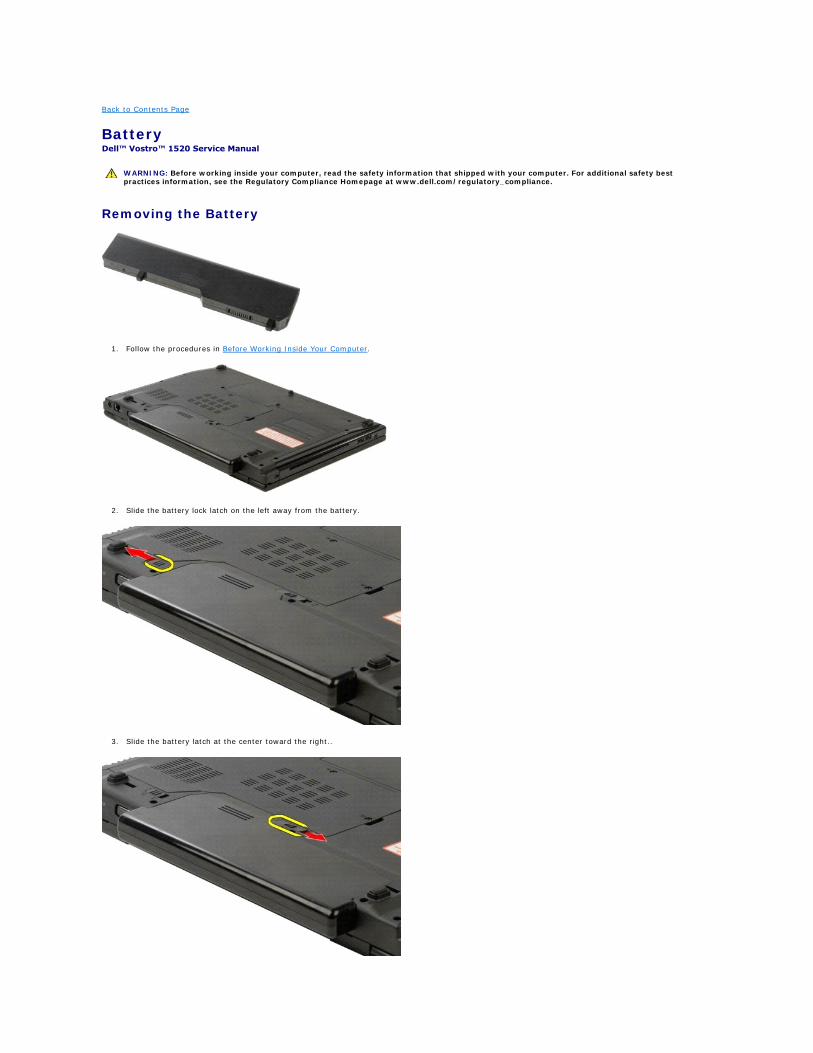
Removing the Battery
1. Follow the procedures in Before Working Inside Your Computer.
2. Slide the battery lock latch on the left away from the battery.
3. Slide the battery latch at the center toward the right..
WARNING: Before working inside your computer, read the safety information that shipped with your computer. For additional safety best practices information, see the Regulatory Compliance Homepage at www.dell.com/regulatory_compliance.
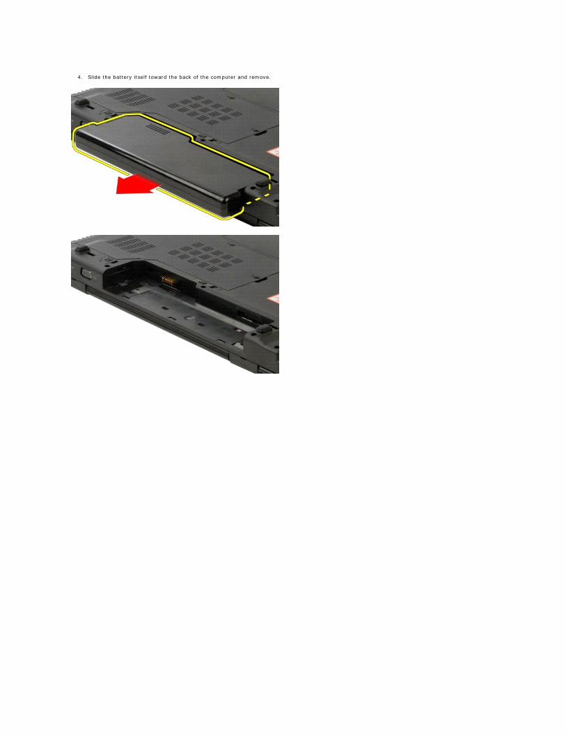
4. Slide the battery itself toward the back of the computer and remove.
Back to Contents Page
Coin-Cell Battery Dell™ Vostro™ 1520 Service Manual
Removing the Coin-Cell Battery
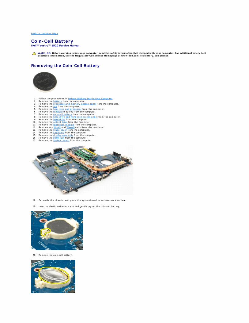
1. Follow the procedures in Before Working Inside Your Computer. 2. Remove the battery from the computer. 3. Remove the processor and memory access panel from the computer. 4. Remove the fan from the computer. 5. Remove the heat sink and processor from the computer. 6. Remove the memory modules from the computer. 7. Remove the coin-cell battery from the computer. 8. Remove the hard drive and mini-card access panel from the computer. 9. Remove the hard drive from the computer.
10. Remove the optical drive from the computer. 11. Remove the Bluetooth module from the computer. 12. Remove any WLAN and WWAN cards from the computer. 13. Remove the hinge cover from the computer. 14. Remove the keyboard from the computer. 15. Remove the display assembly from the computer. 16. Remove the palm rest from the computer. 17. Remove the system board from the computer.
18. Set aside the chassis, and place the systemboard on a clean work surface.
19. Insert a plastic scribe into slot and gently pry up the coin-cell battery.
20. Remove the coin-cell battery.
WARNING: Before working inside your computer, read the safety information that shipped with your computer. For additional safety best practices information, see the Regulatory Compliance Homepage at www.dell.com/regulatory_compliance.

Back to Contents Page
Display Bezel Dell™ Vostro™ 1520 Service Manual
Removing the Display Bezel
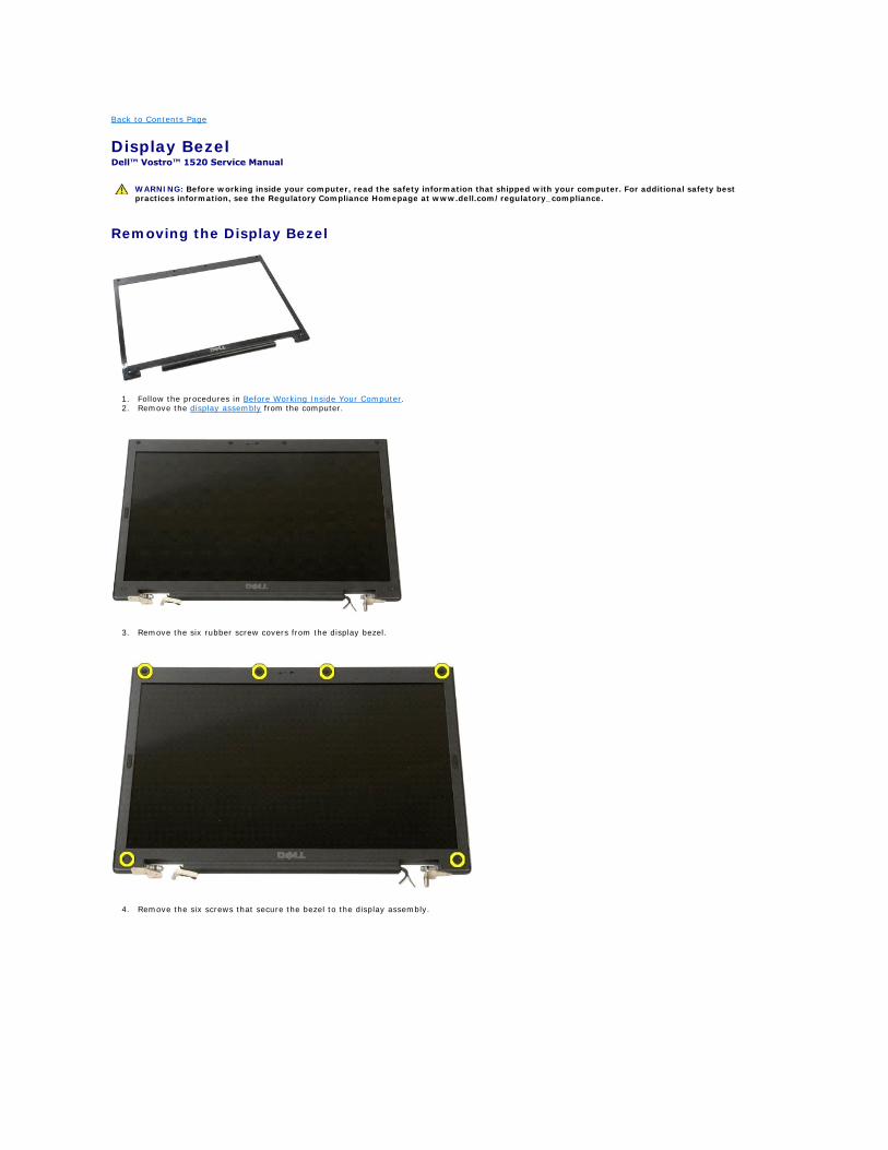
1. Follow the procedures in Before Working Inside Your Computer. 2. Remove the display assembly from the computer.
3. Remove the six rubber screw covers from the display bezel.
4. Remove the six screws that secure the bezel to the display assembly.
WARNING: Before working inside your computer, read the safety information that shipped with your computer. For additional safety best practices information, see the Regulatory Compliance Homepage at www.dell.com/regulatory_compliance.
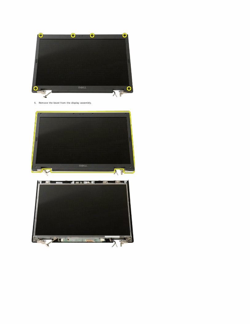
5. Remove the bezel from the display assembly.
Back to Contents Page
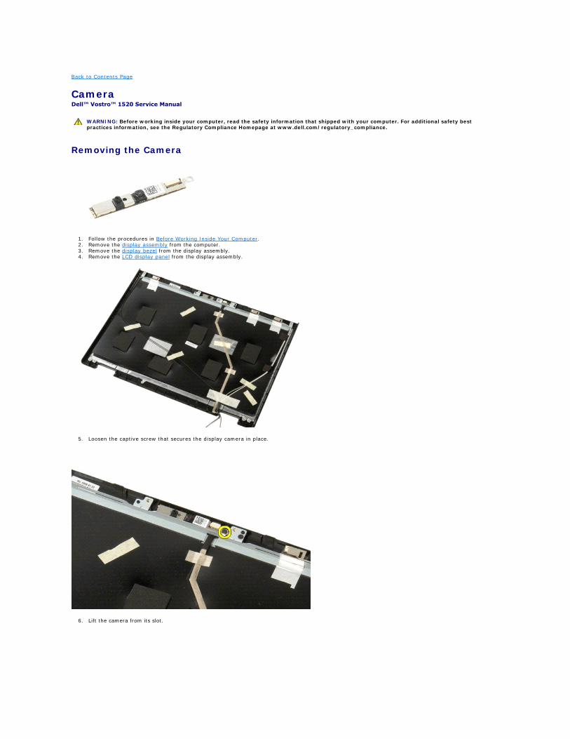
Camera Dell™ Vostro™ 1520 Service Manual
Removing the Camera
1. Follow the procedures in Before Working Inside Your Computer. 2. Remove the display assembly from the computer. 3. Remove the display bezel from the display assembly. 4. Remove the LCD display panel from the display assembly.
5. Loosen the captive screw that secures the display camera in place.
6. Lift the camera from its slot.
WARNING: Before working inside your computer, read the safety information that shipped with your computer. For additional safety best practices information, see the Regulatory Compliance Homepage at www.dell.com/regulatory_compliance.

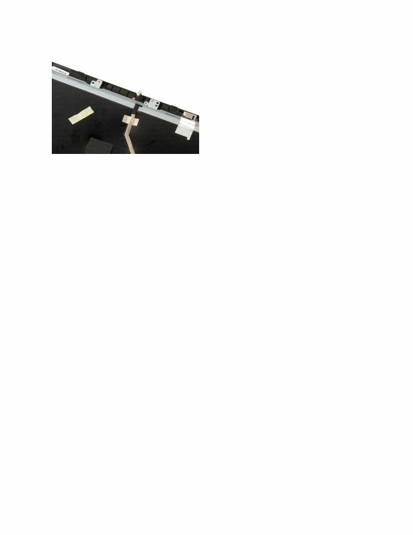
6. Release the display camera data cable from its clip and disconnect the display camera data cable.
7. Remove the display camera from the display assembly.
Back to Contents Page
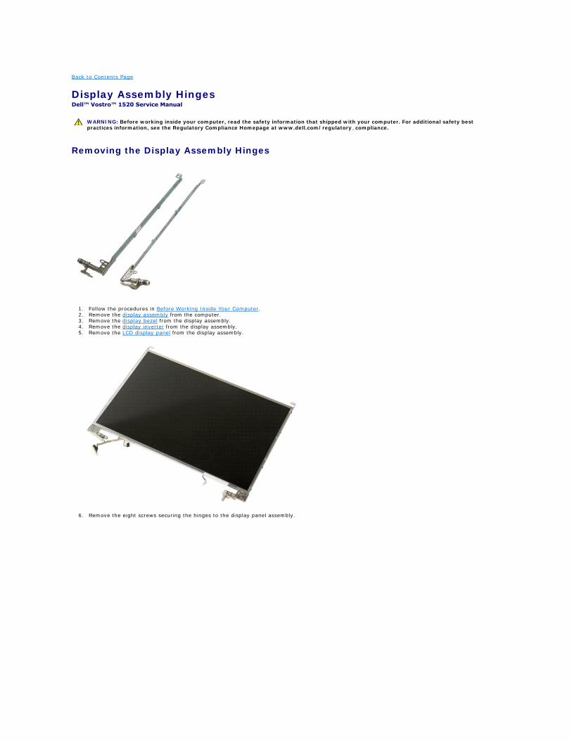
Display Assembly Hinges Dell™ Vostro™ 1520 Service Manual
Removing the Display Assembly Hinges
1. Follow the procedures in Before Working Inside Your Computer. 2. Remove the display assembly from the computer. 3. Remove the display bezel from the display assembly. 4. Remove the display inverter from the display assembly. 5. Remove the LCD display panel from the display assembly.
6. Remove the eight screws securing the hinges to the display panel assembly.
WARNING: Before working inside your computer, read the safety information that shipped with your computer. For additional safety best practices information, see the Regulatory Compliance Homepage at www.dell.com/regulatory_compliance.
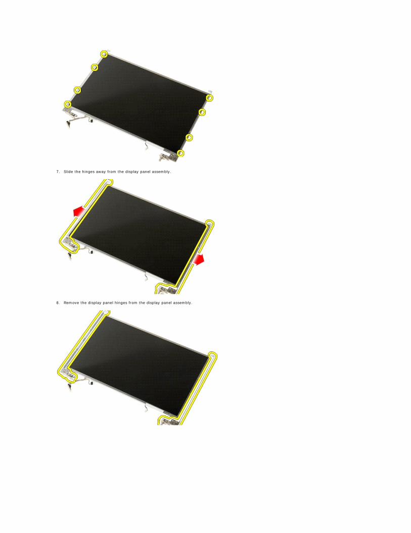
7. Slide the hinges away from the display panel assembly.
8. Remove the display panel hinges from the display panel assembly.

Back to Contents Page
Display Inverter Dell™ Vostro™ 1520 Service Manual
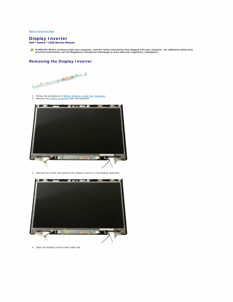
Removing the Display Inverter
1. Follow the procedures in Before Working Inside Your Computer. 2. Remove the display assembly from the computer.
3. Remove the screw that secures the display inverter to the display assembly.
4. Open the display inverter data cable clip.
WARNING: Before working inside your computer, read the safety information that shipped with your computer. For additional safety best practices information, see the Regulatory Compliance Homepage at www.dell.com/regulatory_compliance.
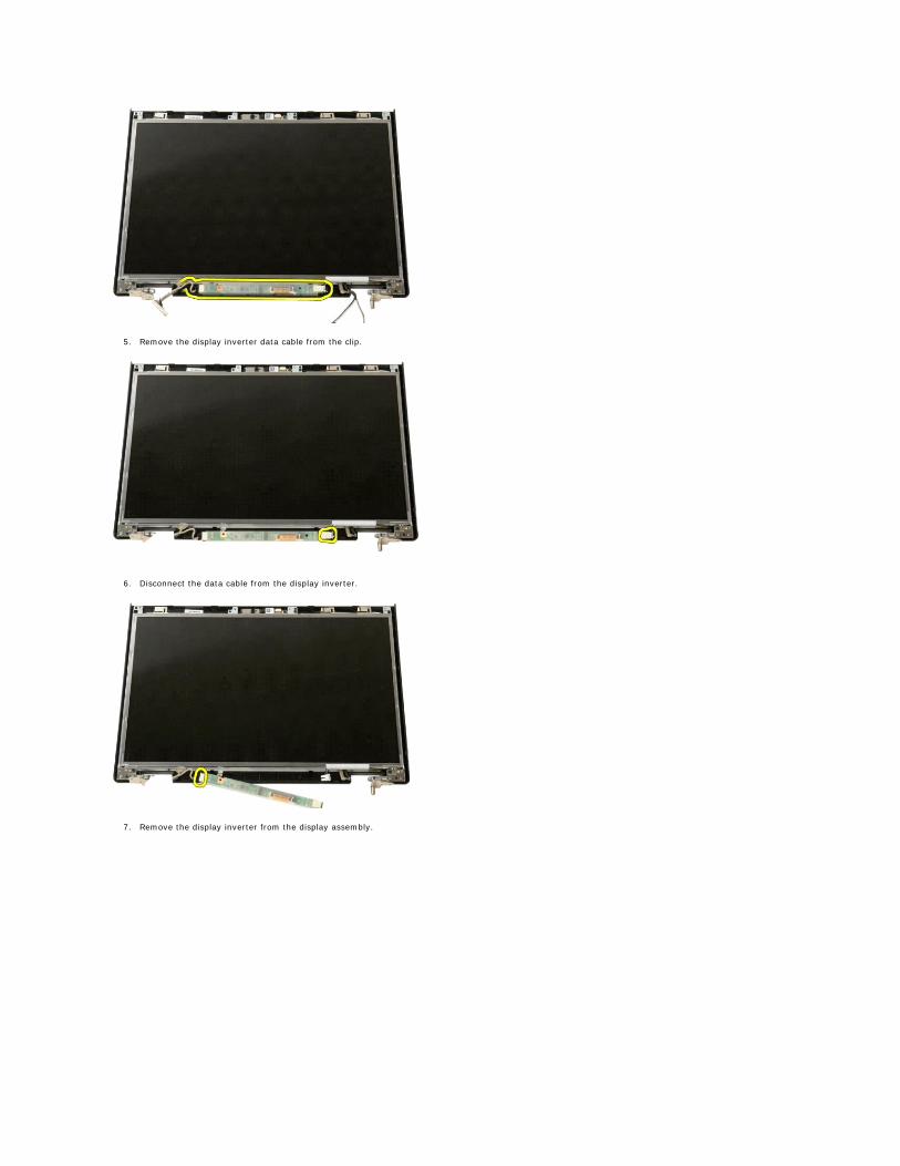
5. Remove the display inverter data cable from the clip.
6. Disconnect the data cable from the display inverter.
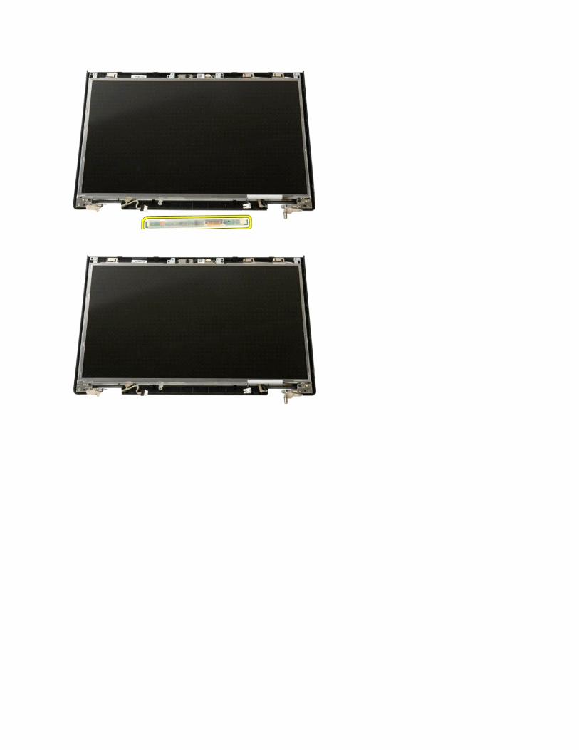
7. Remove the display inverter from the display assembly.
Back to Contents Page
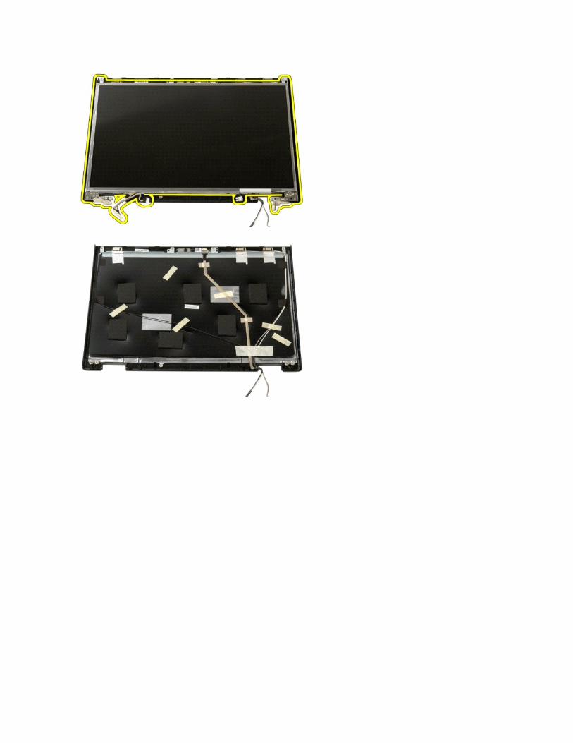
LCD Display Panel Dell™ Vostro™ 1520 Service Manual
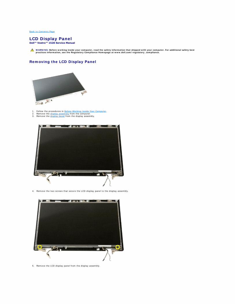
Removing the LCD Display Panel
1. Follow the procedures in Before Working Inside Your Computer. 2. Remove the display assembly from the computer. 3. Remove the display bezel from the display assembly.
4. Remove the two screws that secure the LCD display panel to the display assembly.
5. Remove the LCD display panel from the display assembly.
WARNING: Before working inside your computer, read the safety information that shipped with your computer. For additional safety best practices information, see the Regulatory Compliance Homepage at www.dell.com/regulatory_compliance.
Back to Contents Page
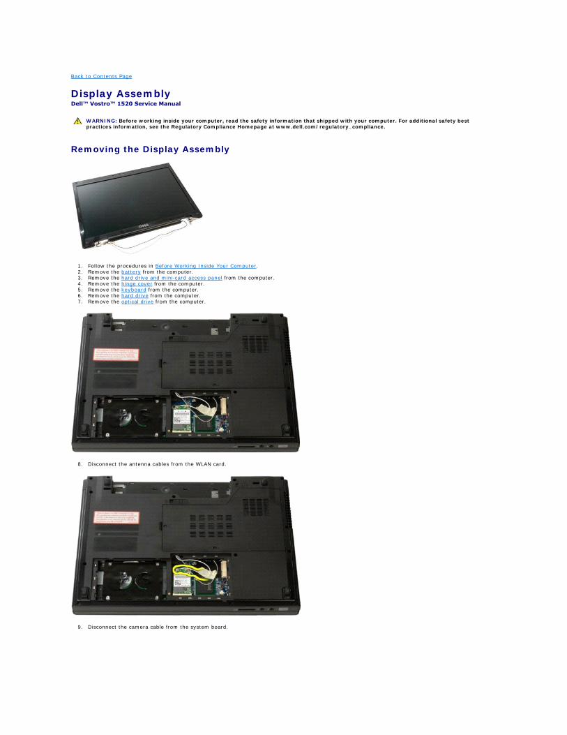
Display Assembly Dell™ Vostro™ 1520 Service Manual
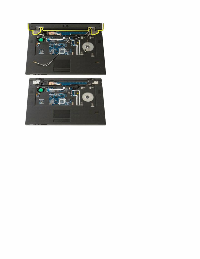
Removing the Display Assembly
1. Follow the procedures in Before Working Inside Your Computer. 2. Remove the battery from the computer. 3. Remove the hard drive and mini-card access panel from the computer. 4. Remove the hinge cover from the computer. 5. Remove the keyboard from the computer. 6. Remove the hard drive from the computer. 7. Remove the optical drive from the computer.
8. Disconnect the antenna cables from the WLAN card.
9. Disconnect the camera cable from the system board.
WARNING: Before working inside your computer, read the safety information that shipped with your computer. For additional safety best practices information, see the Regulatory Compliance Homepage at www.dell.com/regulatory_compliance.
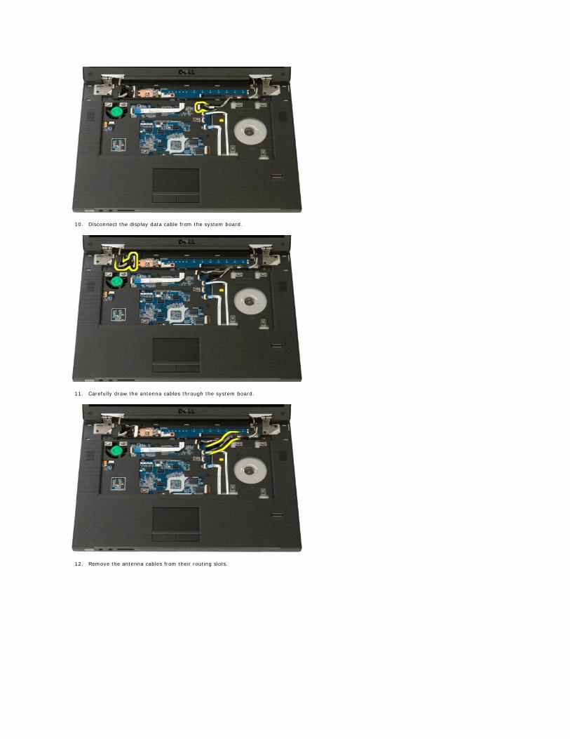
10. Disconnect the display data cable from the system board.
11. Carefully draw the antenna cables through the system board.
12. Remove the antenna cables from their routing slots.
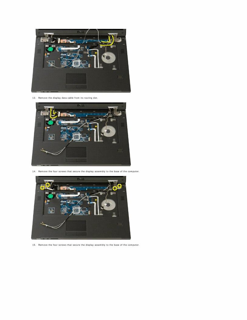
13. Remove the display data cable from its routing slot.
14. Remove the four screws that secure the display assembly to the base of the computer.
15. Remove the four screws that secure the display assembly to the base of the computer.
Back to Contents Page
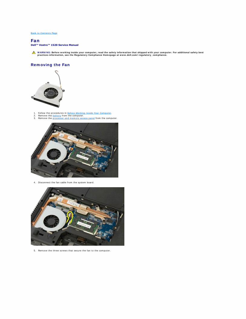
Fan Dell™ Vostro™ 1520 Service Manual
Removing the Fan
1. Follow the procedures in Before Working Inside Your Computer. 2. Remove the battery from the computer. 3. Remove the processor and memory access panel from the computer.
4. Disconnect the fan cable from the system board.
5. Remove the three screws that secure the fan to the computer.
WARNING: Before working inside your computer, read the safety information that shipped with your computer. For additional safety best practices information, see the Regulatory Compliance Homepage at www.dell.com/regulatory_compliance.
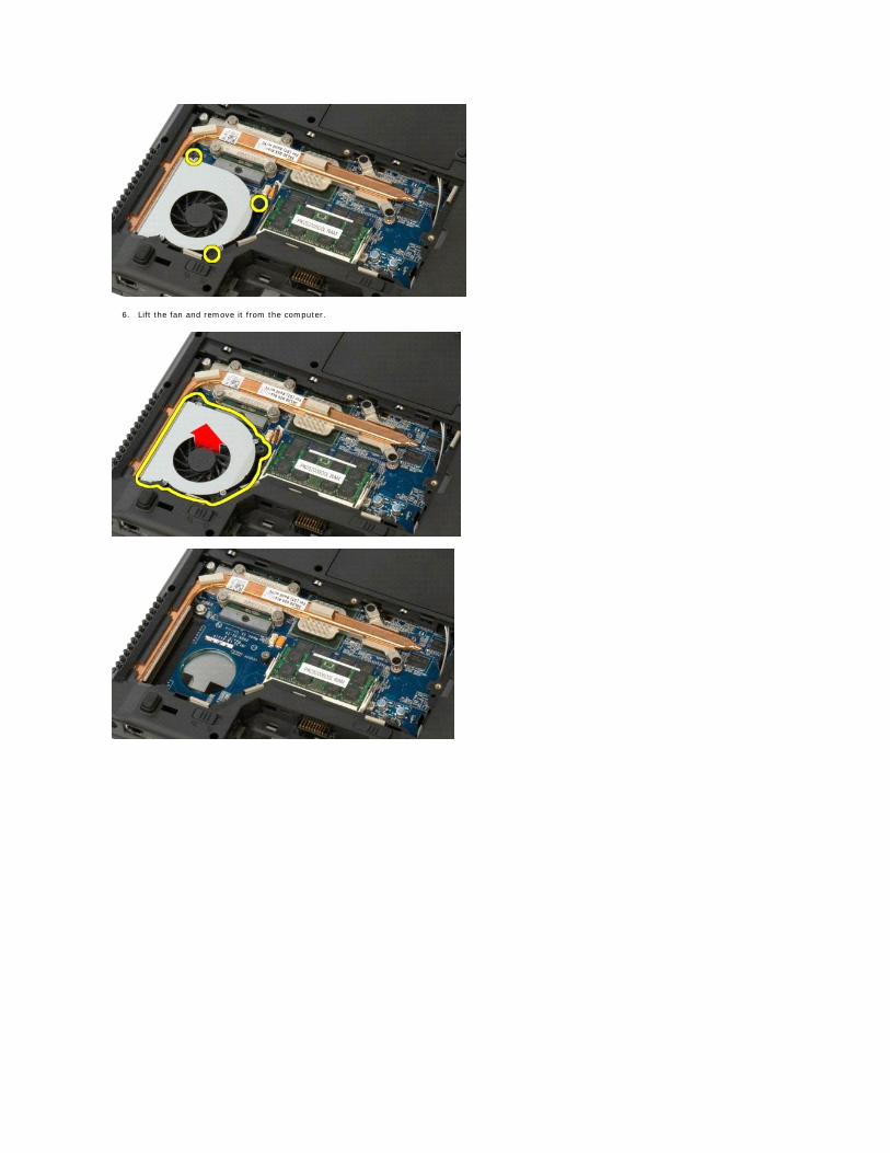
6. Lift the fan and remove it from the computer.
Back to Contents Page
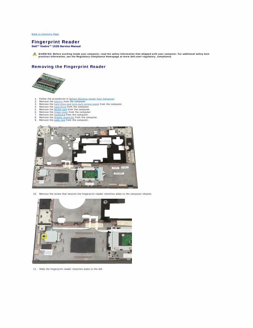
Fingerprint Reader Dell™ Vostro™ 1520 Service Manual
Removing the Fingerprint Reader
1. Follow the procedures in Before Working Inside Your Computer. 2. Remove the battery from the computer. 3. Remove the hard drive and mini-card access panel from the computer. 4. Remove the hard drive from the computer. 5. Remove the WLAN card from the computer. 6. Remove the hinge cover from the computer 7. Remove the keyboard from the computer. 8. Remove the display assembly from the computer. 9. Remove the palm rest from the computer.
10. Remove the screw that secures the fingerprint reader retention plate to the computer chassis.
11. Slide the fingerprint reader retention plate to the left.
WARNING: Before working inside your computer, read the safety information that shipped with your computer. For additional safety best practices information, see the Regulatory Compliance Homepage at www.dell.com/regulatory_compliance.
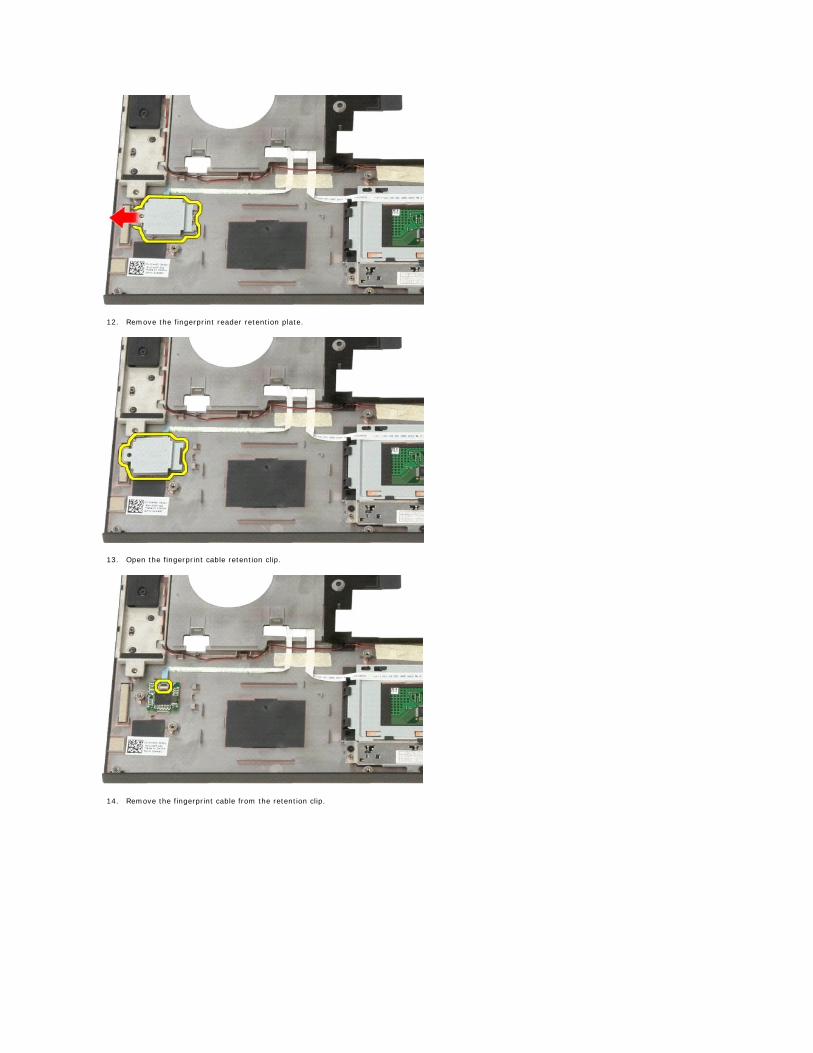
12. Remove the fingerprint reader retention plate.
13. Open the fingerprint cable retention clip.
14. Remove the fingerprint cable from the retention clip.
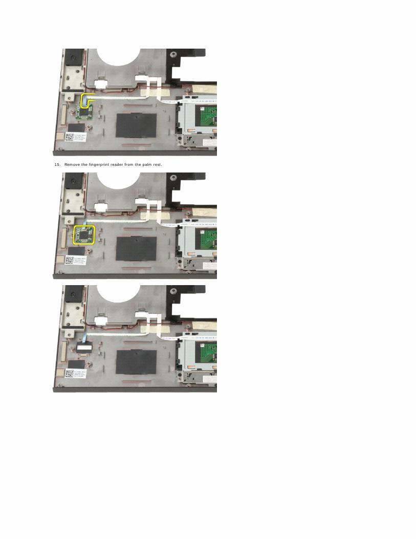
15. Remove the fingerprint reader from the palm rest.
Back to Contents Page
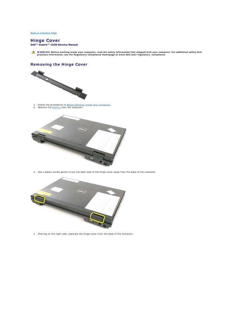
Hinge Cover Dell™ Vostro™ 1520 Service Manual
Removing the Hinge Cover
1. Follow the procedures in Before Working Inside Your Computer. 2. Remove the battery from the computer.
3. Use a plastic scribe gently to pry the back side of the hinge cover away from the base of the computer.
4. Starting on the right side, separate the hinge cover from the base of the computer.
WARNING: Before working inside your computer, read the safety information that shipped with your computer. For additional safety best practices information, see the Regulatory Compliance Homepage at www.dell.com/regulatory_compliance.
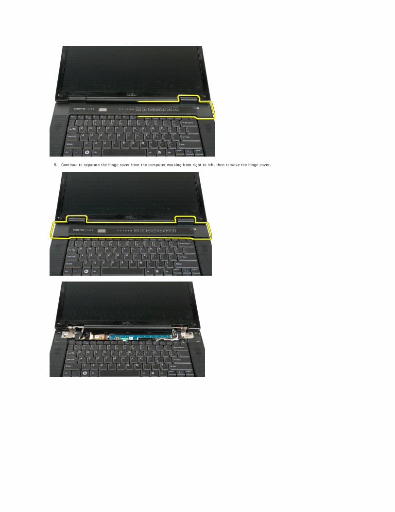
5. Continue to separate the hinge cover from the computer working from right to left, then remove the hinge cover.
Back to Contents Page
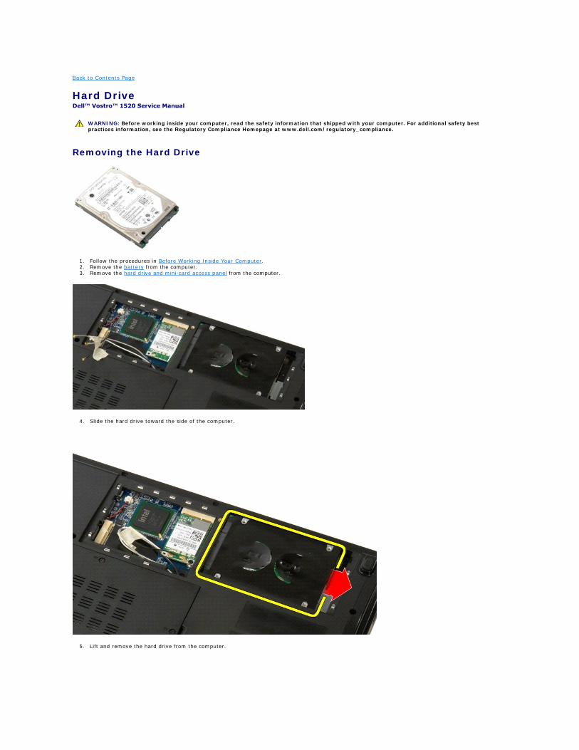
Hard Drive Dell™ Vostro™ 1520 Service Manual
Removing the Hard Drive
1. Follow the procedures in Before Working Inside Your Computer. 2. Remove the battery from the computer. 3. Remove the hard drive and mini-card access panel from the computer.
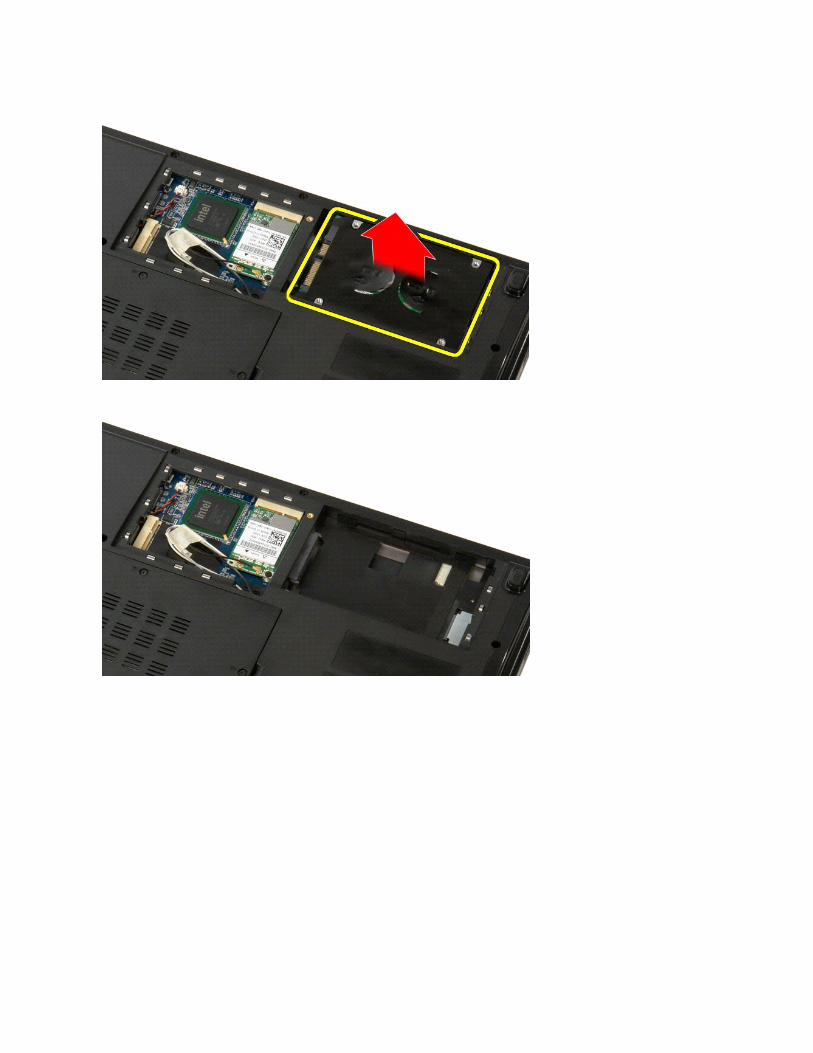
4. Slide the hard drive toward the side of the computer.
5. Lift and remove the hard drive from the computer.
WARNING: Before working inside your computer, read the safety information that shipped with your computer. For additional safety best practices information, see the Regulatory Compliance Homepage at www.dell.com/regulatory_compliance.
Back to Contents Page
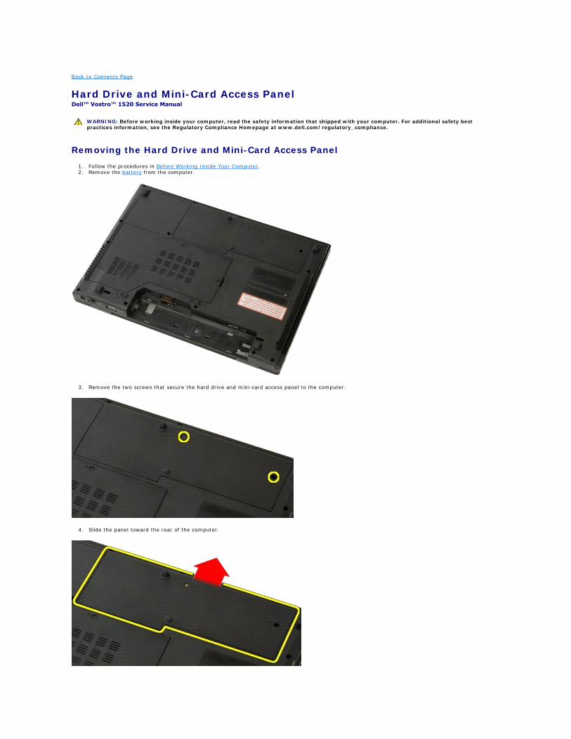
Hard Drive and Mini-Card Access Panel Dell™ Vostro™ 1520 Service Manual
Removing the Hard Drive and Mini-Card Access Panel
1. Follow the procedures in Before Working Inside Your Computer. 2. Remove the battery from the computer.
3. Remove the two screws that secure the hard drive and mini-card access panel to the computer.
4. Slide the panel toward the rear of the computer.
WARNING: Before working inside your computer, read the safety information that shipped with your computer. For additional safety best practices information, see the Regulatory Compliance Homepage at www.dell.com/regulatory_compliance.
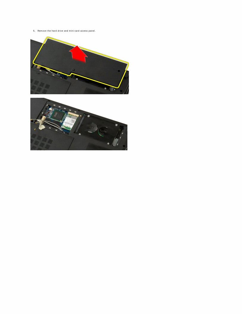
5. Remove the hard drive and mini-card access panel.
Back to Contents Page
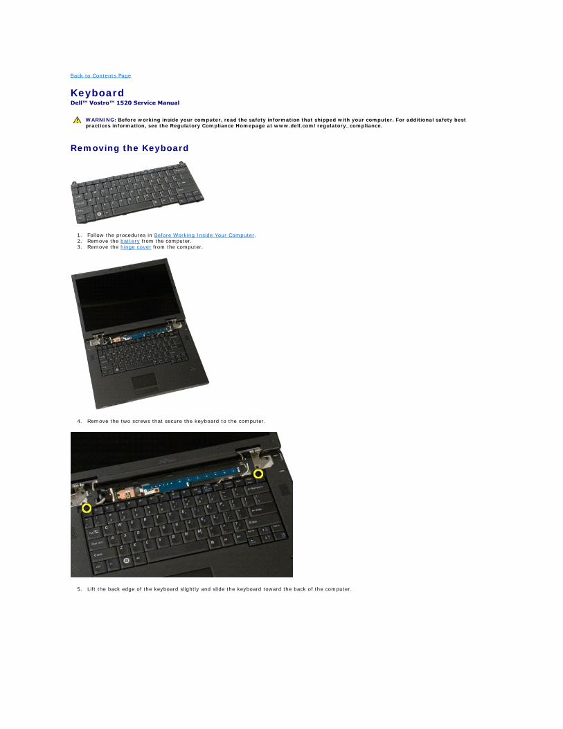
Keyboard Dell™ Vostro™ 1520 Service Manual
Removing the Keyboard
1. Follow the procedures in Before Working Inside Your Computer. 2. Remove the battery from the computer. 3. Remove the hinge cover from the computer.
4. Remove the two screws that secure the keyboard to the computer.
5. Lift the back edge of the keyboard slightly and slide the keyboard toward the back of the computer.
WARNING: Before working inside your computer, read the safety information that shipped with your computer. For additional safety best practices information, see the Regulatory Compliance Homepage at www.dell.com/regulatory_compliance.
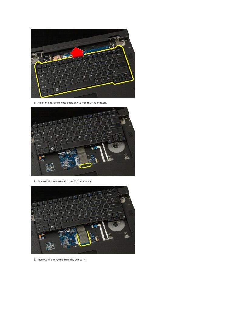
6. Open the keyboard data cable clip to free the ribbon cable.
7. Remove the keyboard data cable from the clip.
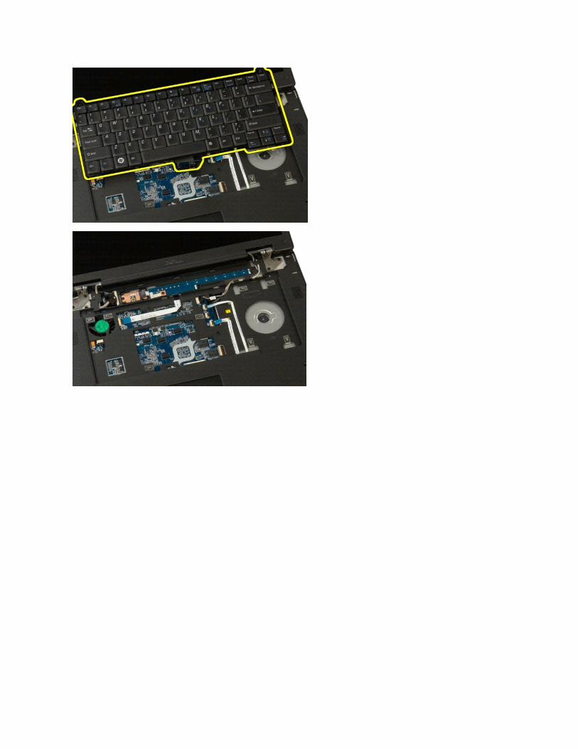
8. Remove the keyboard from the computer.
Back to Contents Page
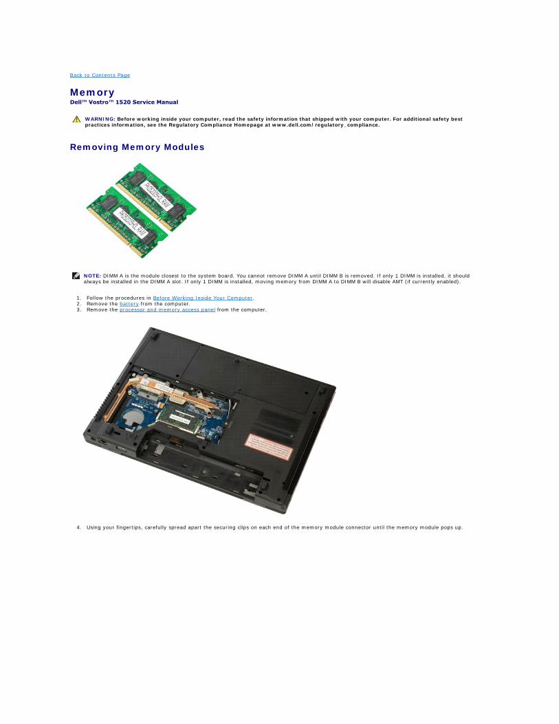
Memory Dell™ Vostro™ 1520 Service Manual
Removing Memory Modules
1. Follow the procedures in Before Working Inside Your Computer. 2. Remove the battery from the computer. 3. Remove the processor and memory access panel from the computer.
4. Using your fingertips, carefully spread apart the securing clips on each end of the memory module connector until the memory module pops up.
WARNING: Before working inside your computer, read the safety information that shipped with your computer. For additional safety best practices information, see the Regulatory Compliance Homepage at www.dell.com/regulatory_compliance.
NOTE: DIMM A is the module closest to the system board. You cannot remove DIMM A until DIMM B is removed. If only 1 DIMM is installed, it should always be installed in the DIMM A slot. If only 1 DIMM is installed, moving memory from DIMM A to DIMM B will disable AMT (if currently enabled).
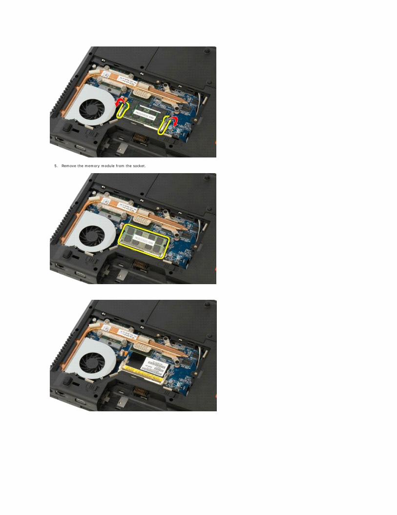
5. Remove the memory module from the socket.
Back to Contents Page
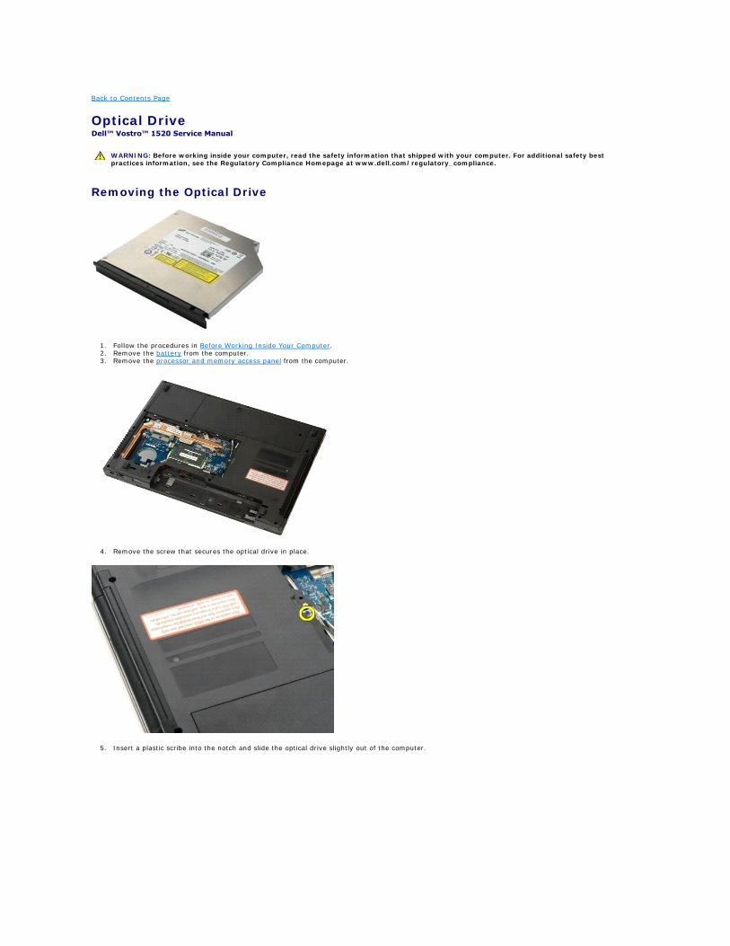
Optical Drive Dell™ Vostro™ 1520 Service Manual
Removing the Optical Drive
1. Follow the procedures in Before Working Inside Your Computer. 2. Remove the battery from the computer. 3. Remove the processor and memory access panel from the computer.
4. Remove the screw that secures the optical drive in place.
5. Insert a plastic scribe into the notch and slide the optical drive slightly out of the computer.
WARNING: Before working inside your computer, read the safety information that shipped with your computer. For additional safety best practices information, see the Regulatory Compliance Homepage at www.dell.com/regulatory_compliance.
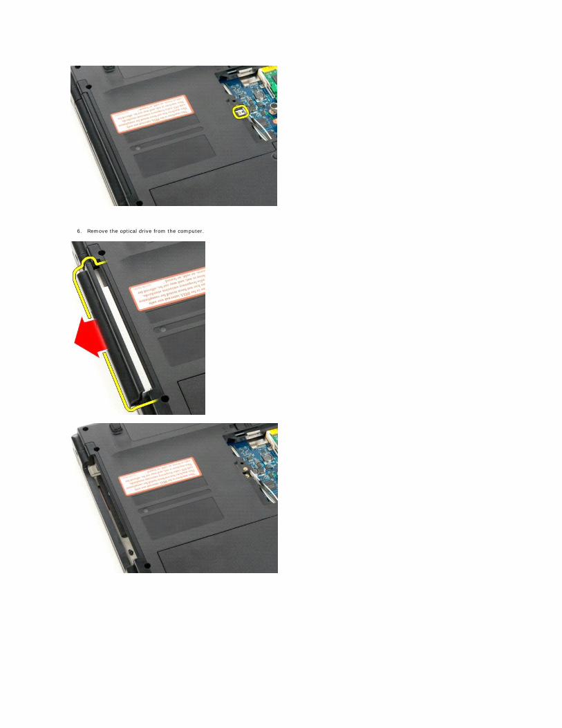
6. Remove the optical drive from the computer.
Back to Contents Page
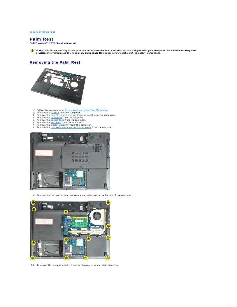
Palm Rest Dell™ Vostro™ 1520 Service Manual
Removing the Palm Rest
1. Follow the procedures in Before Working Inside Your Computer. 2. Remove the battery from the computer. 3. Remove the hard drive and mini-card access panel from the computer. 4. Remove the hard drive from the computer. 5. Remove the optical drive from the computer. 6. Remove the keyboard from the computer. 7. Remove the display assembly from the computer. 8. Remove the processor and memory access panel from the computer.
9. Remove the thirteen screws that secure the palm rest to the bottom of the computer.
10. Turn over the computer and release the fingerprint reader data cable clip.
WARNING: Before working inside your computer, read the safety information that shipped with your computer. For additional safety best practices information, see the Regulatory Compliance Homepage at www.dell.com/regulatory_compliance.
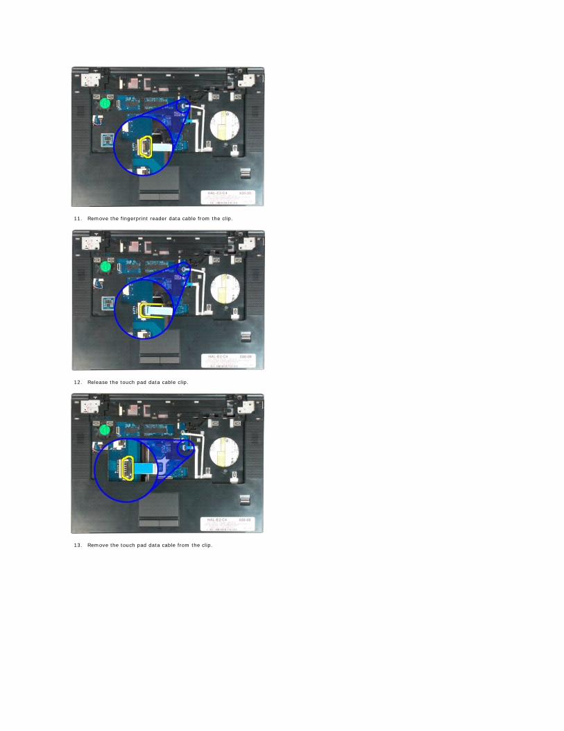
11. Remove the fingerprint reader data cable from the clip.
12. Release the touch pad data cable clip.
13. Remove the touch pad data cable from the clip.
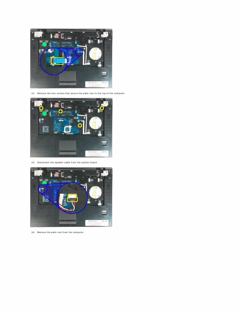
14. Remove the four screws that secure the palm rest to the top of the computer.
15. Disconnect the speaker cable from the system board.
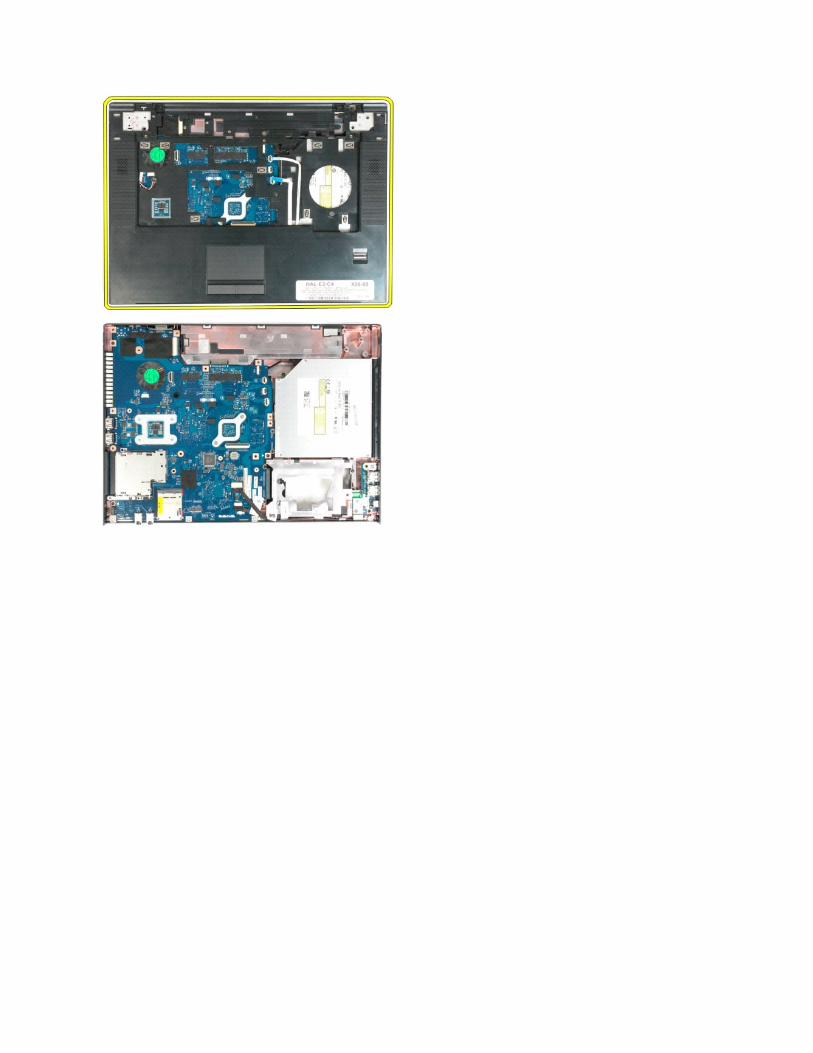
16. Remove the palm rest from the computer.
Back to Contents Page
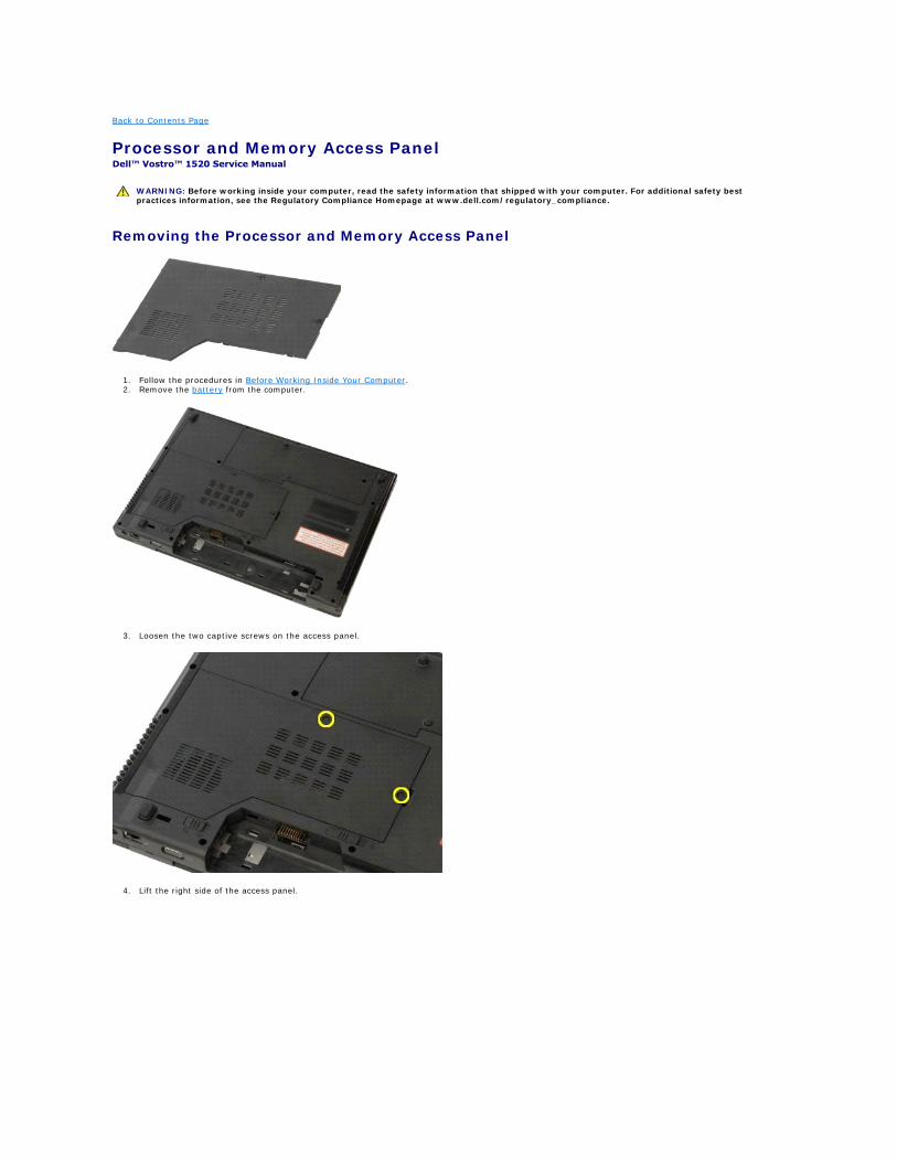
Processor and Memory Access Panel Dell™ Vostro™ 1520 Service Manual
Removing the Processor and Memory Access Panel
1. Follow the procedures in Before Working Inside Your Computer. 2. Remove the battery from the computer.
3. Loosen the two captive screws on the access panel.
4. Lift the right side of the access panel.
WARNING: Before working inside your computer, read the safety information that shipped with your computer. For additional safety best practices information, see the Regulatory Compliance Homepage at www.dell.com/regulatory_compliance.
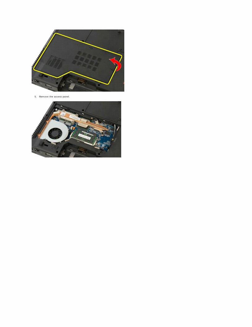
5. Remove the access panel.
Back to Contents Page
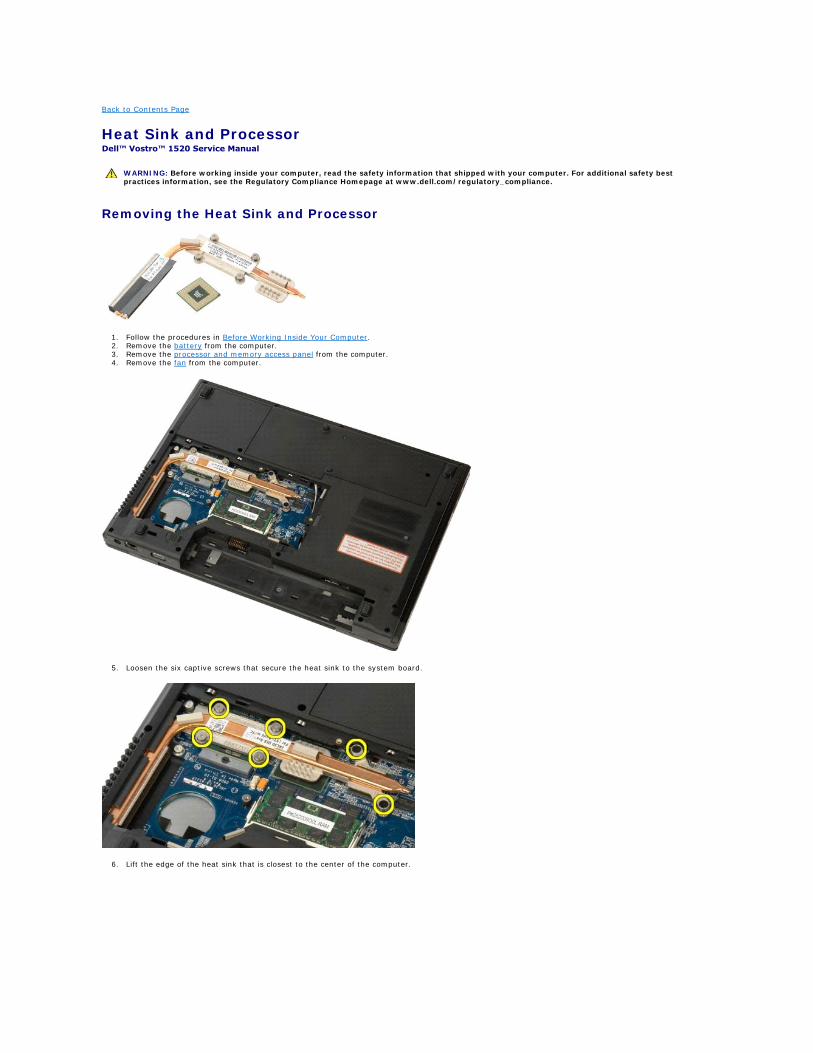
Heat Sink and Processor Dell™ Vostro™ 1520 Service Manual
Removing the Heat Sink and Processor
1. Follow the procedures in Before Working Inside Your Computer. 2. Remove the battery from the computer. 3. Remove the processor and memory access panel from the computer. 4. Remove the fan from the computer.
5. Loosen the six captive screws that secure the heat sink to the system board.
6. Lift the edge of the heat sink that is closest to the center of the computer.
WARNING: Before working inside your computer, read the safety information that shipped with your computer. For additional safety best practices information, see the Regulatory Compliance Homepage at www.dell.com/regulatory_compliance.
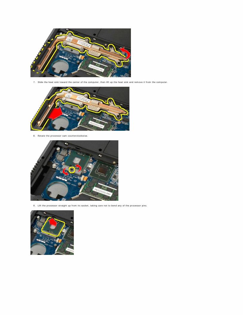
7. Slide the heat sink toward the center of the computer, then lift up the heat sink and remove it from the computer.
8. Rotate the processor cam counterclockwise.
9. Lift the processor straight up from its socket, taking care not to bend any of the processor pins.
Back to Contents Page
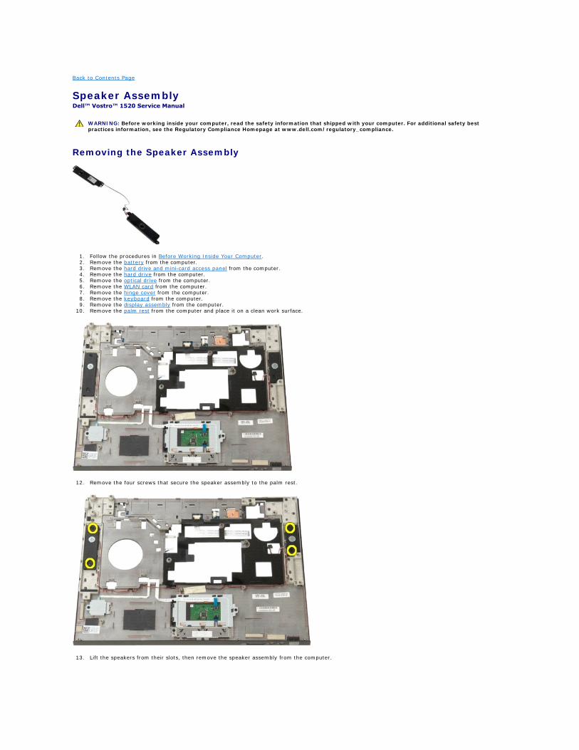
Speaker Assembly Dell™ Vostro™ 1520 Service Manual
Removing the Speaker Assembly
1. Follow the procedures in Before Working Inside Your Computer. 2. Remove the battery from the computer. 3. Remove the hard drive and mini-card access panel from the computer. 4. Remove the hard drive from the computer. 5. Remove the optical drive from the computer. 6. Remove the WLAN card from the computer. 7. Remove the hinge cover from the computer. 8. Remove the keyboard from the computer. 9. Remove the display assembly from the computer.
10. Remove the palm rest from the computer and place it on a clean work surface.
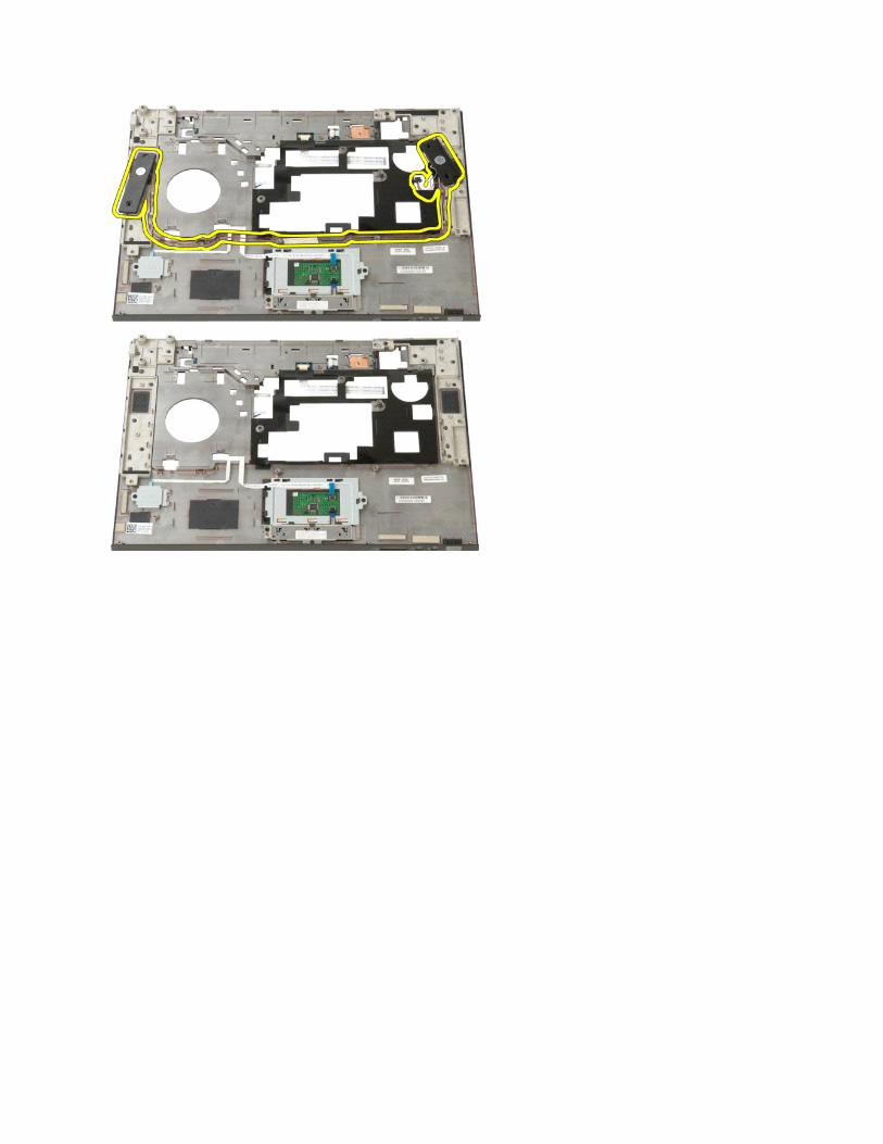
12. Remove the four screws that secure the speaker assembly to the palm rest.
13. Lift the speakers from their slots, then remove the speaker assembly from the computer.
WARNING: Before working inside your computer, read the safety information that shipped with your computer. For additional safety best practices information, see the Regulatory Compliance Homepage at www.dell.com/regulatory_compliance.
Back to Contents Page
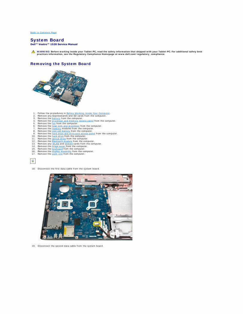
System Board Dell™ Vostro™ 1520 Service Manual
Removing the System Board
1. Follow the procedures in Before Working Inside Your Computer. 2. Remove any ExpressCards and SD cards from the computer. 3. Remove the battery from the computer. 4. Remove the processor and memory access panel from the computer. 5. Remove the fan from the computer. 6. Remove the heat sink and processor from the computer. 7. Remove the memory modules from the computer. 8. Remove the coin-cell battery from the computer. 9. Remove the hard drive and mini-card access panel from the computer.
10. Remove the hard drive from the computer. 11. Remove the optical drive from the computer. 12. Remove the Bluetooth module from the computer. 13. Remove any WLAN and WWAN cards from the computer. 14. Remove the hinge cover from the computer. 15. Remove the keyboard from the computer. 16. Remove the display assembly from the computer. 17. Remove the palm rest from the computer.
18. Disconnect the first data cable from the system board.
19. Disconnect the second data cable from the system board.
WARNING: Before working inside your Tablet-PC, read the safety information that shipped with your Tablet-PC. For additional safety best practices information, see the Regulatory Compliance Homepage at www.dell.com/regulatory_compliance.
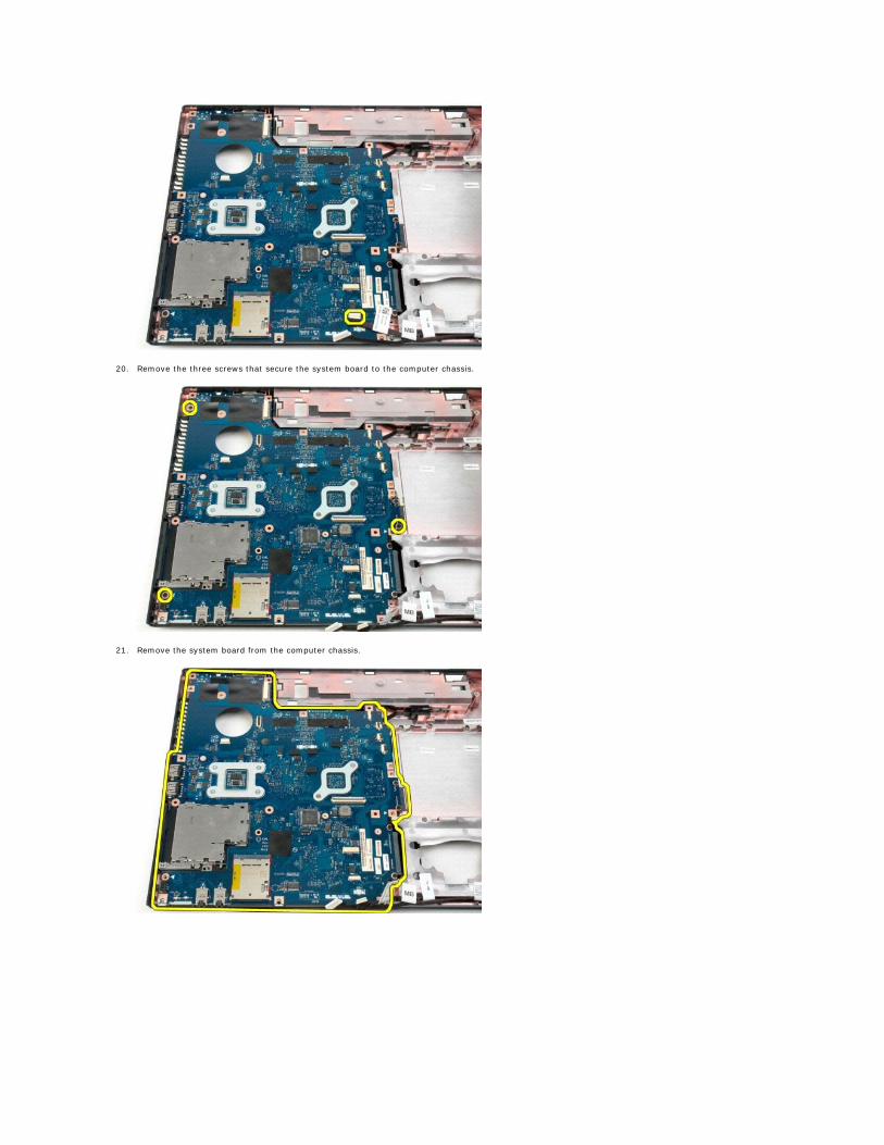
20. Remove the three screws that secure the system board to the computer chassis.
21. Remove the system board from the computer chassis.


Back to Contents Page
USB/IEEE 1394 Board Dell™ Vostro™ 1520 Service Manual
Removing the USB/IEEE 1394 Board
1. Follow the procedures in Before Working Inside Your Computer. 2. Remove the battery from the computer. 3. Remove the processor and memory access panel from the computer. 4. Remove the fan from the computer. 5. Remove the hard drive and mini-card access panel from the computer. 6. Remove the hard drive from the computer. 7. Remove the optical drive from the computer. 8. Remove the hinge cover from the computer. 9. Remove the keyboard from the computer.
10. Remove the display assembly from the computer. 11. Remove the palm rest from the computer.
12. Remove the screw that secures the USB/1394 connector board to the computer chassis.
WARNING: Before working inside your computer, read the safety information that shipped with your computer. For additional safety best practices information, see the Regulatory Compliance Homepage at www.dell.com/regulatory_compliance.
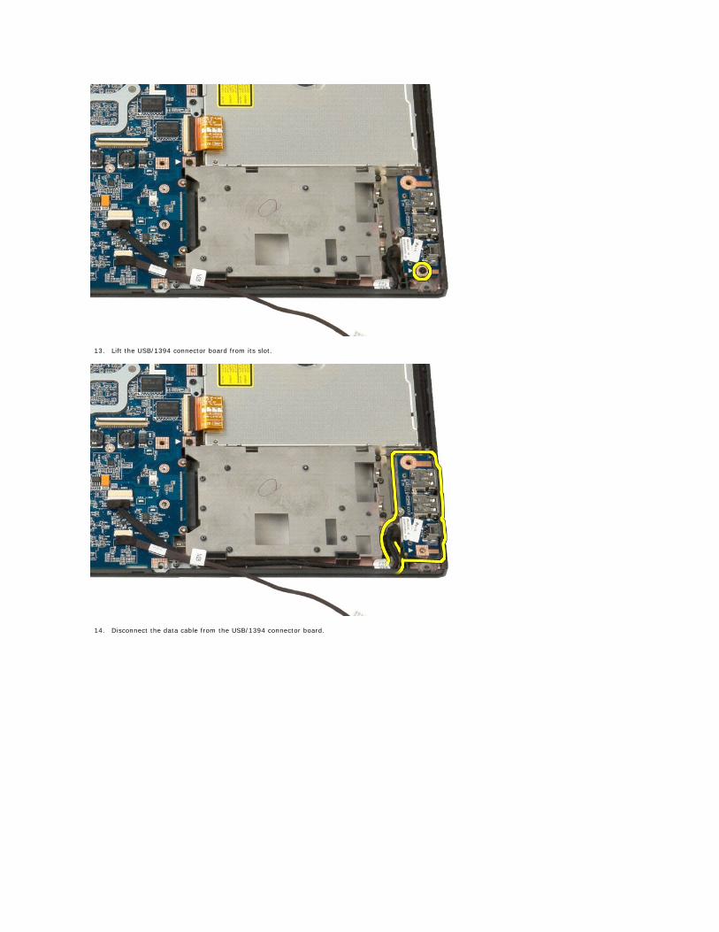
13. Lift the USB/1394 connector board from its slot.
14. Disconnect the data cable from the USB/1394 connector board.
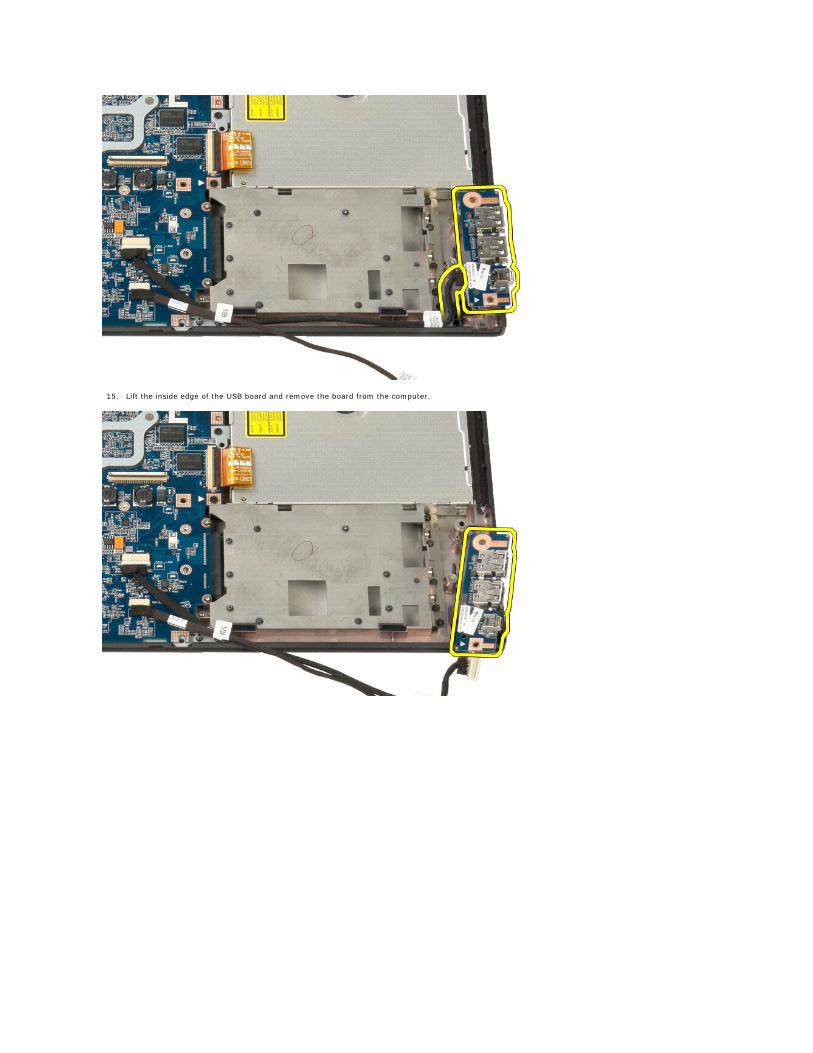
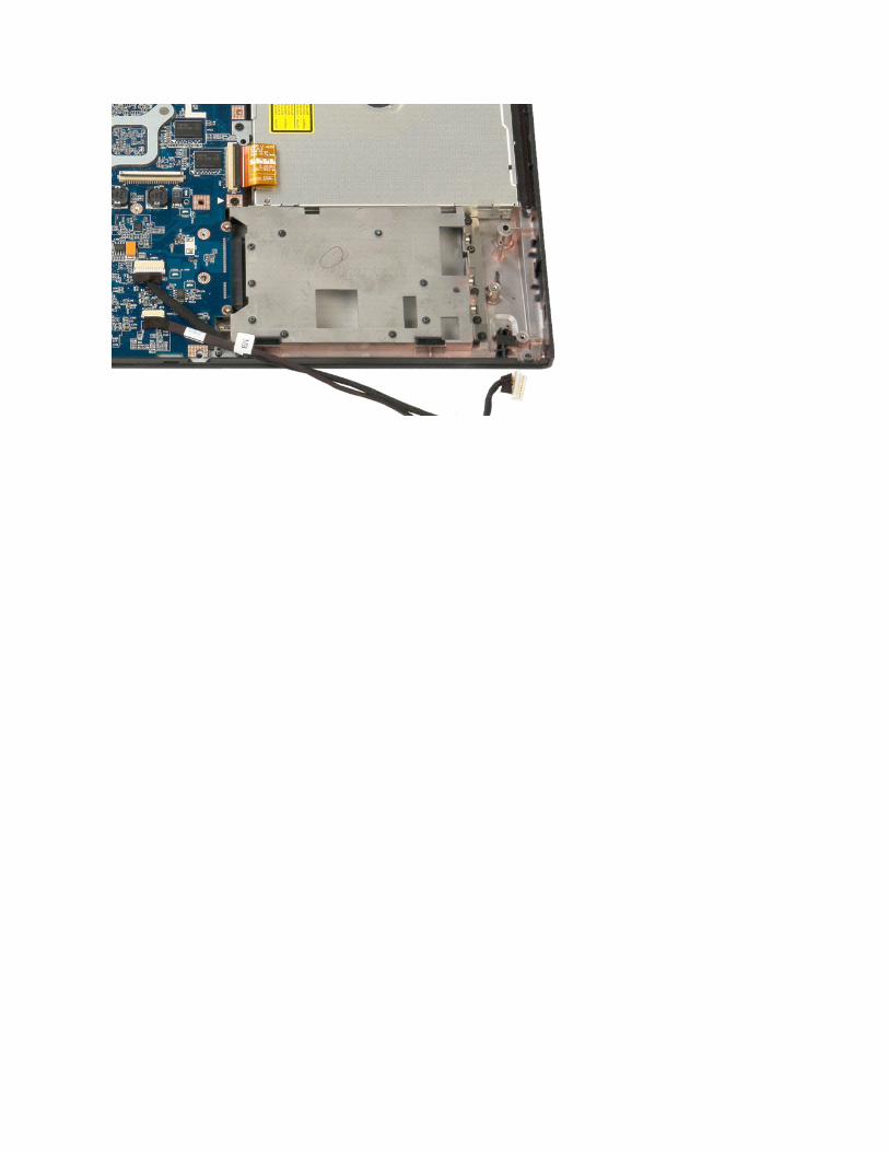
15. Lift the inside edge of the USB board and remove the board from the computer.
Back to Contents Page
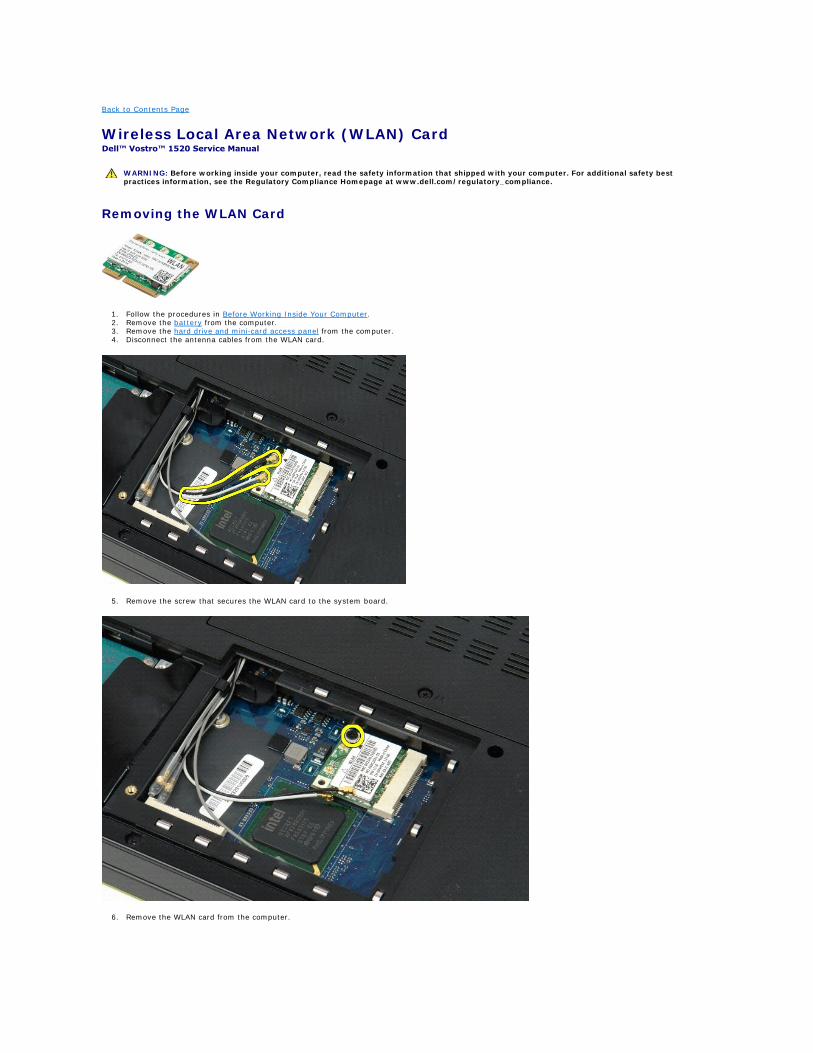
Wireless Local Area Network (WLAN) Card Dell™ Vostro™ 1520 Service Manual
Removing the WLAN Card
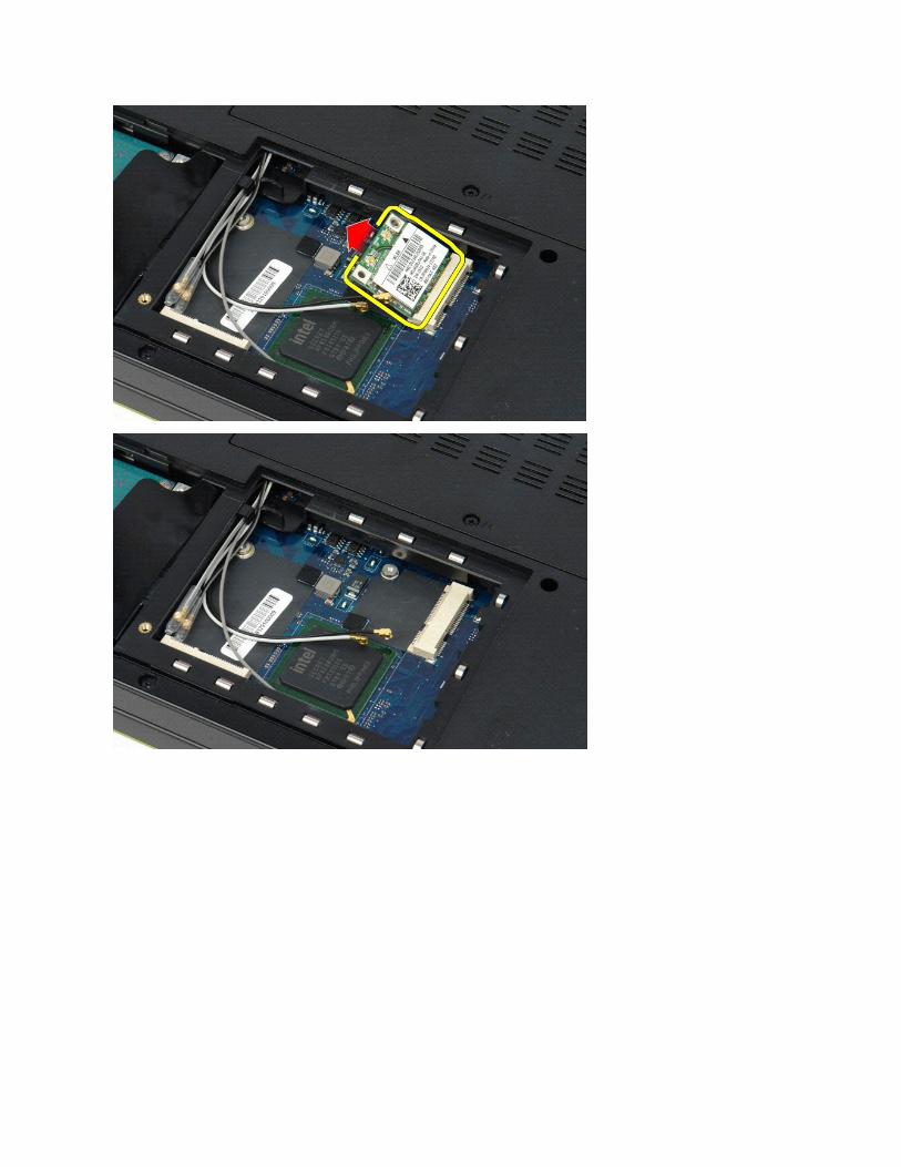
1. Follow the procedures in Before Working Inside Your Computer. 2. Remove the battery from the computer. 3. Remove the hard drive and mini-card access panel from the computer. 4. Disconnect the antenna cables from the WLAN card.
5. Remove the screw that secures the WLAN card to the system board.
6. Remove the WLAN card from the computer.
WARNING: Before working inside your computer, read the safety information that shipped with your computer. For additional safety best practices information, see the Regulatory Compliance Homepage at www.dell.com/regulatory_compliance.
Back to Contents Page
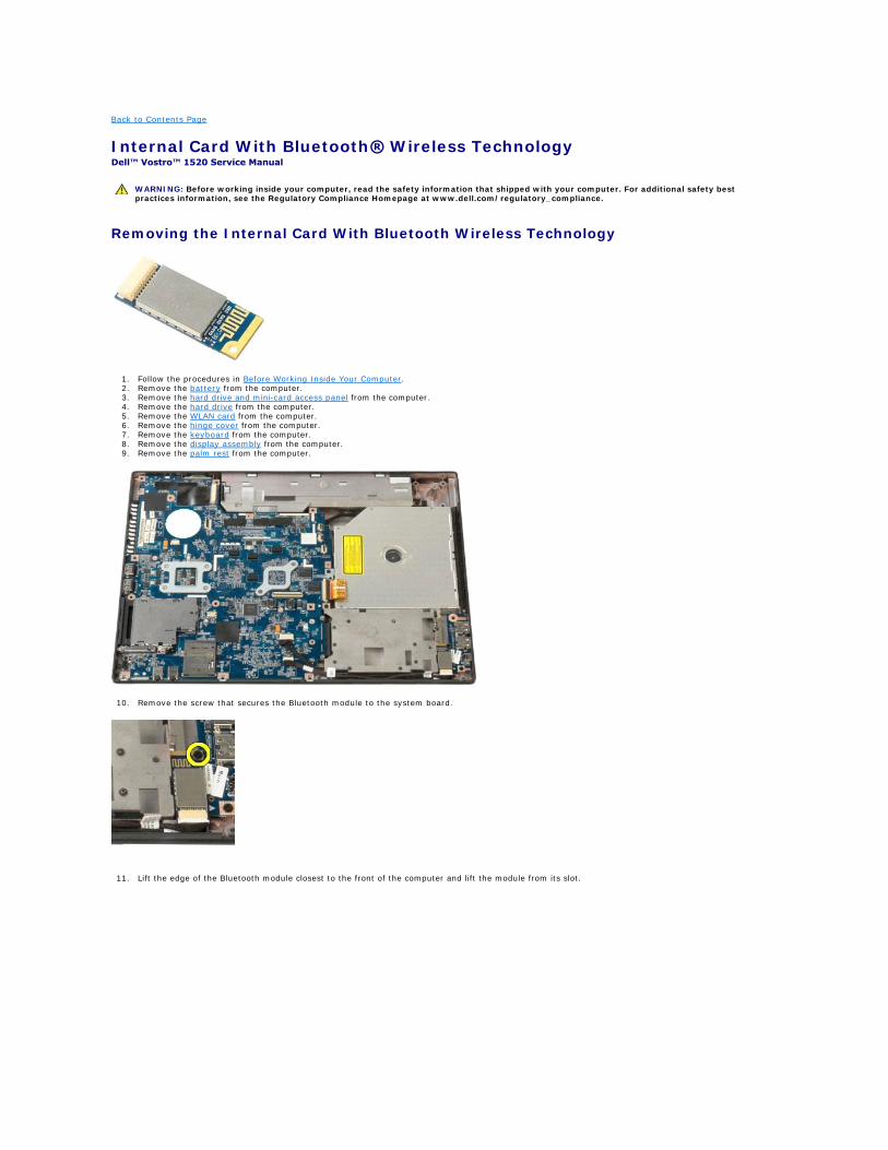
Internal Card With Bluetooth® Wireless Technology Dell™ Vostro™ 1520 Service Manual
Removing the Internal Card With Bluetooth Wireless Technology
1. Follow the procedures in Before Working Inside Your Computer. 2. Remove the battery from the computer. 3. Remove the hard drive and mini-card access panel from the computer. 4. Remove the hard drive from the computer. 5. Remove the WLAN card from the computer. 6. Remove the hinge cover from the computer. 7. Remove the keyboard from the computer. 8. Remove the display assembly from the computer. 9. Remove the palm rest from the computer.
10. Remove the screw that secures the Bluetooth module to the system board.
11. Lift the edge of the Bluetooth module closest to the front of the computer and lift the module from its slot.
WARNING: Before working inside your computer, read the safety information that shipped with your computer. For additional safety best practices information, see the Regulatory Compliance Homepage at www.dell.com/regulatory_compliance.
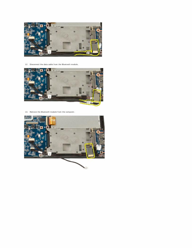
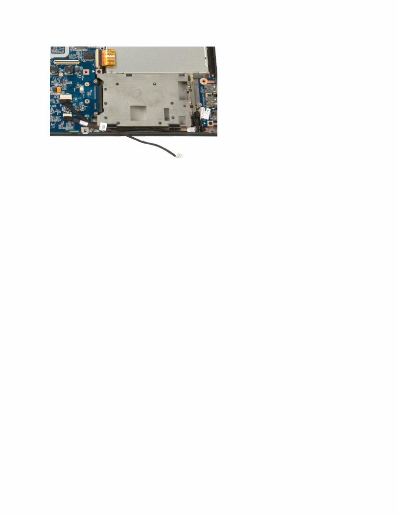
12. Disconnect the data cable from the Bluetooth module.
13. Remove the Bluetooth module from the computer.
Back to Contents Page
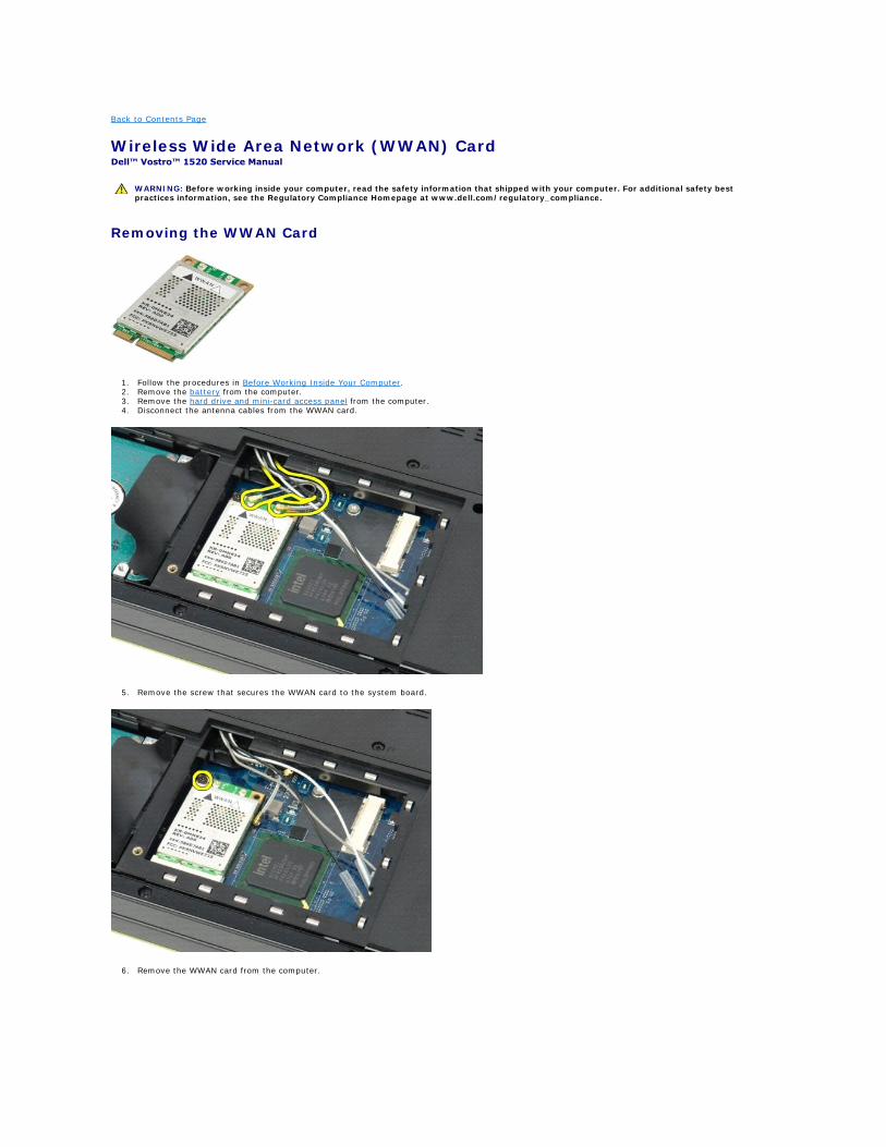
Wireless Wide Area Network (WWAN) Card Dell™ Vostro™ 1520 Service Manual
Removing the WWAN Card
1. Follow the procedures in Before Working Inside Your Computer. 2. Remove the battery from the computer. 3. Remove the hard drive and mini-card access panel from the computer. 4. Disconnect the antenna cables from the WWAN card.
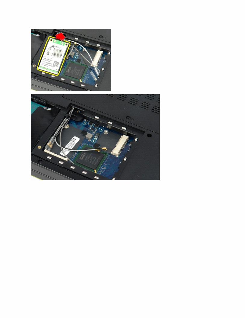
5. Remove the screw that secures the WWAN card to the system board.
6. Remove the WWAN card from the computer.
WARNING: Before working inside your computer, read the safety information that shipped with your computer. For additional safety best practices information, see the Regulatory Compliance Homepage at www.dell.com/regulatory_compliance.
Back to Contents Page
Working on Your Computer Dell™ Vostro™ 1520 Service Manual
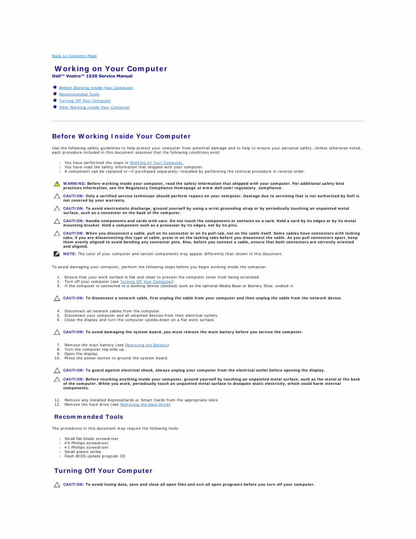
Before Working Inside Your Computer
Use the following safety guidelines to help protect your computer from potential damage and to help to ensure your personal safety. Unless otherwise noted, each procedure included in this document assumes that the following conditions exist:
l You have performed the steps in Working on Your Computer. l You have read the safety information that shipped with your computer. l A component can be replaced or—if purchased separately—installed by performing the removal procedure in reverse order.
To avoid damaging your computer, perform the following steps before you begin working inside the computer.
1. Ensure that your work surface is flat and clean to prevent the computer cover from being scratched. 2. Turn off your computer (see Turning Off Your Computer). 3. If the computer is connected to a docking device (docked) such as the optional Media Base or Battery Slice, undock it.
4. Disconnect all network cables from the computer. 5. Disconnect your computer and all attached devices from their electrical outlets. 6. Close the display and turn the computer upside-down on a flat work surface.
7. Remove the main battery (see Removing the Battery). 8. Turn the computer top-side up. 9. Open the display.
10. Press the power button to ground the system board.
11. Remove any installed ExpressCards or Smart Cards from the appropriate slots. 12. Remove the hard drive (see Removing the Hard Drive).
Recommended Tools
The procedures in this document may require the following tools:
l Small flat-blade screwdriver l #0 Phillips screwdriver l #1 Phillips screwdriver l Small plastic scribe l Flash BIOS update program CD
Turning Off Your Computer
Before Working Inside Your Computer
Recommended Tools
Turning Off Your Computer
After Working Inside Your Computer
WARNING: Before working inside your computer, read the safety information that shipped with your computer. For additional safety best practices information, see the Regulatory Compliance Homepage at www.dell.com/regulatory_compliance.
CAUTION: Only a certified service technician should perform repairs on your computer. Damage due to servicing that is not authorized by Dell is not covered by your warranty.
CAUTION: To avoid electrostatic discharge, ground yourself by using a wrist grounding strap or by periodically touching an unpainted metal surface, such as a connector on the back of the computer.
CAUTION: Handle components and cards with care. Do not touch the components or contacts on a card. Hold a card by its edges or by its metal mounting bracket. Hold a component such as a processor by its edges, not by its pins.
CAUTION: When you disconnect a cable, pull on its connector or on its pull-tab, not on the cable itself. Some cables have connectors with locking tabs; if you are disconnecting this type of cable, press in on the locking tabs before you disconnect the cable. As you pull connectors apart, keep them evenly aligned to avoid bending any connector pins. Also, before you connect a cable, ensure that both connectors are correctly oriented and aligned.
NOTE: The color of your computer and certain components may appear differently than shown in this document.
CAUTION: To disconnect a network cable, first unplug the cable from your computer and then unplug the cable from the network device.
CAUTION: To avoid damaging the system board, you must remove the main battery before you service the computer.
CAUTION: To guard against electrical shock, always unplug your computer from the electrical outlet before opening the display.
CAUTION: Before touching anything inside your computer, ground yourself by touching an unpainted metal surface, such as the metal at the back of the computer. While you work, periodically touch an unpainted metal surface to dissipate static electricity, which could harm internal components.
CAUTION: To avoid losing data, save and close all open files and exit all open programs before you turn off your computer.
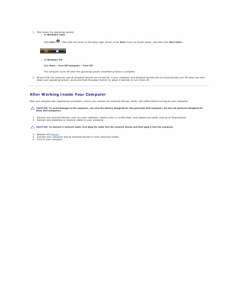
1. Shut down the operating system: l In Windows Vista:
Click Start , then click the arrow in the lower-right corner of the Start menu as shown below, and then click Shut Down.
l In Windows XP:
Click Start® Turn Off Computer® Turn Off.
The computer turns off after the operating system shutdown process is complete.
2. Ensure that the computer and all attached devices are turned off. If your computer and attached devices did not automatically turn off when you shut down your operating system, press and hold the power button for about 4 seconds to turn them off.
After Working Inside Your Computer
After you complete any replacement procedure, ensure you connect any external devices, cards, and cables before turning on your computer.
1. Connect any external devices, such as a port replicator, battery slice, or media base, and replace any cards, such as an ExpressCard. 2. Connect any telephone or network cables to your computer.
3. Replace the battery. 4. Connect your computer and all attached devices to their electrical outlets. 5. Turn on your computer.
CAUTION: To avoid damage to the computer, use only the battery designed for this particular Dell computer. Do not use batteries designed for other Dell computers.
CAUTION: To connect a network cable, first plug the cable into the network device and then plug it into the computer.


![Vostro 1520 Manual de service...Ap sa i pe pentru a accesa System Setup (Configurare sistem) úi a modifica set rile specifice utilizatorului. Dac nu pute LDFFHVDFRQILJXUDUHDXWLOL]kQG](https://img.pdfslide.net/doc/110x75/60685a2f6e1bd858723c92f4/vostro-1520-manual-de-service-ap-sa-i-pe-pentru-a-accesa-system-setup-configurare.jpg)