Embed Size (px)
Citation preview
VRC 8900 Radio Terminal
Product Reference Guide

2
VRC 8900 Radio Terminal
Product Reference Guide
72-55775-04
Revision A
August 2003

ii
© 2002-2003 by Symbol Technologies, Inc. All rights reserved.
No part of this publication may be reproduced or used in any form, or by any electrical or mechanical means, without permission in writing from Symbol. This includes electronic or mechanical means, such as photocopying, recording, or information storage and retrieval systems. The material in this manual is subject to change without notice.
The software is provided strictly on an “as is” basis. All software, including firmware, furnished to the user is on a licensed basis. Symbol grants to the user a non-transferable and non-exclusive license to use each software or firmware program delivered hereunder (licensed program). Except as noted below, such license may not be assigned, sublicensed, or otherwise transferred by the user without prior written consent of Symbol. No right to copy a licensed program in whole or in part is granted, except as permitted under copyright law. The user shall not modify, merge, or incorporate any form or portion of a licensed program with other program material, create a derivative work from a licensed program, or use a licensed program in a network without written permission from Symbol. The user agrees to maintain Symbol’s copyright notice on the licensed programs delivered hereunder, and to include the same on any authorized copies it makes, in whole or in part. The user agrees not to decompile, disassemble, decode, or reverse engineer any licensed program delivered to the user or any portion thereof.
Symbol reserves the right to make changes to any software or product to improve reliability, function, or design.
Symbol does not assume any product liability arising out of, or in connection with, the application or use of any product, circuit, or application described herein.
No license is granted, either expressly or by implication, estoppel, or otherwise under any Symbol Technologies, Inc., intellectual property rights. An implied license only exists for equipment, circuits, and subsystems contained in Symbol products.
Symbol, Spectrum One, and Spectrum24 are registered trademarks of Symbol Technologies, Inc. Other product names mentioned in this manual may be trademarks or registered trademarks of their respective companies and are hereby acknowledged.
Symbol Technologies, Inc.One Symbol PlazaHoltsville, New York 11742-1300http://www.symbol.com
Contents
About This GuideIntroduction . . . . . . . . . . . . . . . . . . . . . . . . . . . . . . . . . . . . . . . . . . . . . . . . . . . . . . . . . . . . . . . . . . . viiChapter Descriptions . . . . . . . . . . . . . . . . . . . . . . . . . . . . . . . . . . . . . . . . . . . . . . . . . . . . . . . . . . . . viiNotational Conventions . . . . . . . . . . . . . . . . . . . . . . . . . . . . . . . . . . . . . . . . . . . . . . . . . . . . . . . . . . viiiRelated Documents . . . . . . . . . . . . . . . . . . . . . . . . . . . . . . . . . . . . . . . . . . . . . . . . . . . . . . . . . . . . . viiiService Information . . . . . . . . . . . . . . . . . . . . . . . . . . . . . . . . . . . . . . . . . . . . . . . . . . . . . . . . . . . . . viii
Symbol Support Center . . . . . . . . . . . . . . . . . . . . . . . . . . . . . . . . . . . . . . . . . . . . . . . . . . . . . . . ix
Chapter 1. Getting StartedIntroduction . . . . . . . . . . . . . . . . . . . . . . . . . . . . . . . . . . . . . . . . . . . . . . . . . . . . . . . . . . . . . . . . . . 1-1
The VRC 8900 . . . . . . . . . . . . . . . . . . . . . . . . . . . . . . . . . . . . . . . . . . . . . . . . . . . . . . . . . . . . 1-1Unpacking the Terminal . . . . . . . . . . . . . . . . . . . . . . . . . . . . . . . . . . . . . . . . . . . . . . . . . . . . . . . . . 1-2Parts of the Terminal . . . . . . . . . . . . . . . . . . . . . . . . . . . . . . . . . . . . . . . . . . . . . . . . . . . . . . . . . . . 1-2Accessories and Peripherals . . . . . . . . . . . . . . . . . . . . . . . . . . . . . . . . . . . . . . . . . . . . . . . . . . . . . 1-3
Optional Accessories . . . . . . . . . . . . . . . . . . . . . . . . . . . . . . . . . . . . . . . . . . . . . . . . . . . . . . . 1-3Radio Cards . . . . . . . . . . . . . . . . . . . . . . . . . . . . . . . . . . . . . . . . . . . . . . . . . . . . . . . . . . . . . . 1-4SDK . . . . . . . . . . . . . . . . . . . . . . . . . . . . . . . . . . . . . . . . . . . . . . . . . . . . . . . . . . . . . . . . . . . . 1-4
Chapter 2. Installing the TerminalIntroduction . . . . . . . . . . . . . . . . . . . . . . . . . . . . . . . . . . . . . . . . . . . . . . . . . . . . . . . . . . . . . . . . . . 2-1Installing Your Terminal . . . . . . . . . . . . . . . . . . . . . . . . . . . . . . . . . . . . . . . . . . . . . . . . . . . . . . . . . 2-2
Positioning the Terminal . . . . . . . . . . . . . . . . . . . . . . . . . . . . . . . . . . . . . . . . . . . . . . . . . . . . . 2-2Routing Electrical Cables . . . . . . . . . . . . . . . . . . . . . . . . . . . . . . . . . . . . . . . . . . . . . . . . . . . . 2-3Installation Kit Contents . . . . . . . . . . . . . . . . . . . . . . . . . . . . . . . . . . . . . . . . . . . . . . . . . . . . . 2-4Installing the Terminal . . . . . . . . . . . . . . . . . . . . . . . . . . . . . . . . . . . . . . . . . . . . . . . . . . . . . . 2-5
Providing Power to the Terminal . . . . . . . . . . . . . . . . . . . . . . . . . . . . . . . . . . . . . . . . . . . . . . . . . . 2-7Connecting AC Power to Your Terminal. . . . . . . . . . . . . . . . . . . . . . . . . . . . . . . . . . . . . . . . . 2-9Connecting the Filtered DC Power Cable for Electric Trucks . . . . . . . . . . . . . . . . . . . . . . . . 2-10
Connecting the Cable . . . . . . . . . . . . . . . . . . . . . . . . . . . . . . . . . . . . . . . . . . . . . . . . . . . . . . . . . 2-10
iii
VRC 8900 Radio Terminal Product Reference Guide
Installation and the Internal Battery. . . . . . . . . . . . . . . . . . . . . . . . . . . . . . . . . . . . . . . . . . . . . . . . 2-12The Optional Keyboard . . . . . . . . . . . . . . . . . . . . . . . . . . . . . . . . . . . . . . . . . . . . . . . . . . . . . . . . . 2-13
Attaching the Keyboard . . . . . . . . . . . . . . . . . . . . . . . . . . . . . . . . . . . . . . . . . . . . . . . . . . . . . 2-13Adjusting the Keyboard . . . . . . . . . . . . . . . . . . . . . . . . . . . . . . . . . . . . . . . . . . . . . . . . . . . . . 2-15
Chapter 3. Software Installation on the Development PCIntroduction . . . . . . . . . . . . . . . . . . . . . . . . . . . . . . . . . . . . . . . . . . . . . . . . . . . . . . . . . . . . . . . . . . . 3-1Symbol Windows CE SDK . . . . . . . . . . . . . . . . . . . . . . . . . . . . . . . . . . . . . . . . . . . . . . . . . . . . . . . 3-2
Installing the SDK on the Development PC . . . . . . . . . . . . . . . . . . . . . . . . . . . . . . . . . . . . . . . 3-2
Chapter 4. Operating the TerminalIntroduction . . . . . . . . . . . . . . . . . . . . . . . . . . . . . . . . . . . . . . . . . . . . . . . . . . . . . . . . . . . . . . . . . . . 4-1Powering on the VRC 8900. . . . . . . . . . . . . . . . . . . . . . . . . . . . . . . . . . . . . . . . . . . . . . . . . . . . . . . 4-1Booting the Terminal . . . . . . . . . . . . . . . . . . . . . . . . . . . . . . . . . . . . . . . . . . . . . . . . . . . . . . . . . . . 4-2
Performing a Warm Boot . . . . . . . . . . . . . . . . . . . . . . . . . . . . . . . . . . . . . . . . . . . . . . . . . . . . . 4-2Performing a Cold Boot . . . . . . . . . . . . . . . . . . . . . . . . . . . . . . . . . . . . . . . . . . . . . . . . . . . . . . 4-3Methods of Suspension . . . . . . . . . . . . . . . . . . . . . . . . . . . . . . . . . . . . . . . . . . . . . . . . . . . . . . 4-3
Programmable (“P”) Keys . . . . . . . . . . . . . . . . . . . . . . . . . . . . . . . . . . . . . . . . . . . . . . . . . . . . . . . . 4-4Using the Keyboard. . . . . . . . . . . . . . . . . . . . . . . . . . . . . . . . . . . . . . . . . . . . . . . . . . . . . . . . . . . . . 4-5
Adjusting the Keyboard . . . . . . . . . . . . . . . . . . . . . . . . . . . . . . . . . . . . . . . . . . . . . . . . . . . . . . 4-5Locking the Desktop . . . . . . . . . . . . . . . . . . . . . . . . . . . . . . . . . . . . . . . . . . . . . . . . . . . . . . . . . . . . 4-9Calibrating the Screen. . . . . . . . . . . . . . . . . . . . . . . . . . . . . . . . . . . . . . . . . . . . . . . . . . . . . . . . . . . 4-9
Calibrating Using the Display. . . . . . . . . . . . . . . . . . . . . . . . . . . . . . . . . . . . . . . . . . . . . . . . . . 4-9Calibrating Using the Keyboard . . . . . . . . . . . . . . . . . . . . . . . . . . . . . . . . . . . . . . . . . . . . . . . 4-12
Adjusting the Brightness . . . . . . . . . . . . . . . . . . . . . . . . . . . . . . . . . . . . . . . . . . . . . . . . . . . . . . . . 4-16Adjusting the Volume . . . . . . . . . . . . . . . . . . . . . . . . . . . . . . . . . . . . . . . . . . . . . . . . . . . . . . . . . . 4-16Connecting Accessories . . . . . . . . . . . . . . . . . . . . . . . . . . . . . . . . . . . . . . . . . . . . . . . . . . . . . . . . 4-17Displaying Bar Code Information . . . . . . . . . . . . . . . . . . . . . . . . . . . . . . . . . . . . . . . . . . . . . . . . . 4-17Saving Files and Allocating Memory. . . . . . . . . . . . . . . . . . . . . . . . . . . . . . . . . . . . . . . . . . . . . . . 4-19
Flash File System . . . . . . . . . . . . . . . . . . . . . . . . . . . . . . . . . . . . . . . . . . . . . . . . . . . . . . . . . 4-19DRAM File System. . . . . . . . . . . . . . . . . . . . . . . . . . . . . . . . . . . . . . . . . . . . . . . . . . . . . . . . . 4-19
Chapter 5. Spectrum24 Network ConfigurationIntroduction . . . . . . . . . . . . . . . . . . . . . . . . . . . . . . . . . . . . . . . . . . . . . . . . . . . . . . . . . . . . . . . . . . . 5-1Configuring Your 2 Mbps Terminal . . . . . . . . . . . . . . . . . . . . . . . . . . . . . . . . . . . . . . . . . . . . . . . . . 5-1Configuring Your 11 Mbps Terminal . . . . . . . . . . . . . . . . . . . . . . . . . . . . . . . . . . . . . . . . . . . . . . . . 5-8NICTT . . . . . . . . . . . . . . . . . . . . . . . . . . . . . . . . . . . . . . . . . . . . . . . . . . . . . . . . . . . . . . . . . . . . . . 5-16
Mode Tab. . . . . . . . . . . . . . . . . . . . . . . . . . . . . . . . . . . . . . . . . . . . . . . . . . . . . . . . . . . . . . . . 5-16Info Tab . . . . . . . . . . . . . . . . . . . . . . . . . . . . . . . . . . . . . . . . . . . . . . . . . . . . . . . . . . . . . . . . . 5-17IP Config Tab. . . . . . . . . . . . . . . . . . . . . . . . . . . . . . . . . . . . . . . . . . . . . . . . . . . . . . . . . . . . . 5-18Power Tab . . . . . . . . . . . . . . . . . . . . . . . . . . . . . . . . . . . . . . . . . . . . . . . . . . . . . . . . . . . . . . . 5-19
iv

Contents
Options Tab . . . . . . . . . . . . . . . . . . . . . . . . . . . . . . . . . . . . . . . . . . . . . . . . . . . . . . . . . . . . . 5-21Encryption Tab . . . . . . . . . . . . . . . . . . . . . . . . . . . . . . . . . . . . . . . . . . . . . . . . . . . . . . . . . . . 5-22Ping Tab . . . . . . . . . . . . . . . . . . . . . . . . . . . . . . . . . . . . . . . . . . . . . . . . . . . . . . . . . . . . . . . . 5-23Signal Tab . . . . . . . . . . . . . . . . . . . . . . . . . . . . . . . . . . . . . . . . . . . . . . . . . . . . . . . . . . . . . . 5-24APs Tab . . . . . . . . . . . . . . . . . . . . . . . . . . . . . . . . . . . . . . . . . . . . . . . . . . . . . . . . . . . . . . . . 5-25
Chapter 6. Configuring the TerminalIntroduction . . . . . . . . . . . . . . . . . . . . . . . . . . . . . . . . . . . . . . . . . . . . . . . . . . . . . . . . . . . . . . . . . . 6-1Flash Partitions . . . . . . . . . . . . . . . . . . . . . . . . . . . . . . . . . . . . . . . . . . . . . . . . . . . . . . . . . . . . . . . 6-1
FFS Partitions. . . . . . . . . . . . . . . . . . . . . . . . . . . . . . . . . . . . . . . . . . . . . . . . . . . . . . . . . . . . . 6-1Non-FFS Partitions . . . . . . . . . . . . . . . . . . . . . . . . . . . . . . . . . . . . . . . . . . . . . . . . . . . . . . . . . 6-2
Downloading the Operating System . . . . . . . . . . . . . . . . . . . . . . . . . . . . . . . . . . . . . . . . . . . . . . . 6-2Downloading Applications . . . . . . . . . . . . . . . . . . . . . . . . . . . . . . . . . . . . . . . . . . . . . . . . . . . . . . . 6-7
Chapter 7. ActiveSyncIntroduction . . . . . . . . . . . . . . . . . . . . . . . . . . . . . . . . . . . . . . . . . . . . . . . . . . . . . . . . . . . . . . . . . . 7-1Performing an ActiveSync . . . . . . . . . . . . . . . . . . . . . . . . . . . . . . . . . . . . . . . . . . . . . . . . . . . . . . . 7-2
Chapter 8. Maintenance and TroubleshootingMaintaining the Terminal . . . . . . . . . . . . . . . . . . . . . . . . . . . . . . . . . . . . . . . . . . . . . . . . . . . . . . . . 8-1Cleaning the Terminal . . . . . . . . . . . . . . . . . . . . . . . . . . . . . . . . . . . . . . . . . . . . . . . . . . . . . . . . . . 8-1Storage . . . . . . . . . . . . . . . . . . . . . . . . . . . . . . . . . . . . . . . . . . . . . . . . . . . . . . . . . . . . . . . . . . . . . 8-1Troubleshooting . . . . . . . . . . . . . . . . . . . . . . . . . . . . . . . . . . . . . . . . . . . . . . . . . . . . . . . . . . . . . . . 8-2
Appendix A. SpecificationsEnvironment. . . . . . . . . . . . . . . . . . . . . . . . . . . . . . . . . . . . . . . . . . . . . . . . . . . . . . . . . . . . . . . . . . A-1Pin-Outs. . . . . . . . . . . . . . . . . . . . . . . . . . . . . . . . . . . . . . . . . . . . . . . . . . . . . . . . . . . . . . . . . . . . . A-3
Index
Tell Us What You Think...
v

VRC 8900 Radio Terminal Product Reference Guide
vi

About This Guide
Introduction
The VRC 8900 Radio Terminal Product Reference Guide provides general instructions for setting up, initializing, operating, troubleshooting and maintaining the VRC 8900 Radio Terminal.
Chapter Descriptions
• Chapter 1, Getting Started, describes how to set up the terminal.
• Chapter 2, Installing the Terminal, provides instructions on installing the terminal in a vehicle.
• Chapter 3, Software Installation on the Development PC, provides information on the Software Developer’s Kit.
• Chapter 4, Operating the Terminal, provides detailed instructions on how to use the terminal.
• Chapter 5, Spectrum24 Network Configuration, describes the utilities that monitor and configure the Spectrum24 wireless connection.
• Chapter 6, Configuring the Terminal, describes options for configuring the terminal to assist in planning your application development.
• Chapter 7, ActiveSync, explains how to use ActiveSync® for communications between the terminal and host PC.
• Chapter 8, Maintenance and Troubleshooting, provides information about possible problems with the terminal and suggested solutions to these problems.
• Appendix A, Specifications, details the technical specifications of the product.
vii
VRC 8900 Radio Terminal Product Reference Guide
Notational Conventions
The following conventions are used in this document:
• Italics are used to highlight specific items in the general text, and to identify chapters and sections in this and related documents. It also identifies names of screens, menus, menu items, and fields within screens.
• Courier text identifies buttons to be tapped or clicked on screens.
• Bullets (•) indicate:
• action items
• lists of alternatives
• lists of required steps that are not necessarily sequential
• Sequential lists (e.g., those that describe step-by-step procedures) appear as numbered lists.
Related Documents
• VRC 8900 Radio Terminal Quick Reference Guide, p/n 72-50137-xx
• VRC 7900/8900 DC Power Cable Quick Reference Guide, p/n 72-57649-xx
Service Information
If you have a problem with your equipment, contact the Symbol Support Center for your region. See page ix for contact information. Before calling, have the model number, serial number, and several of your bar code symbols at hand.
Call the Support Center from a phone near the scanning equipment so that the service person can try to talk you through your problem. If the equipment is found to be working properly and the problem is symbol readability, the Support Center will request samples of your bar codes for analysis at our plant.
If your problem cannot be solved over the phone, you may need to return your equipment for servicing. If that is necessary, you will be given specific directions.
Note: Symbol Technologies is not responsible for any damages incurred during shipment if the approved shipping container is not used.
viii

About This Guide
Shipping the units improperly can possibly void the warranty. If the original shipping container was not kept, contact Symbol to have another sent to you.
Symbol Support CenterFor service information, warranty information or technical assistance contact or call the Symbol Support Center in:
United StatesSymbol Technologies, Inc.One Symbol PlazaHoltsville, New York 11742-1300Tel: 1-800-653-5350
CanadaSymbol Technologies Canada, Inc.2540 Matheson Boulevard EastMississauga, Ontario, Canada L4W 4Z2Tel: 905-629-7226
United KingdomSymbol TechnologiesSymbol PlaceWinnersh Triangle, Berkshire RG41 5TPUnited Kingdom
Tel: 0800 328 2424 (Inside UK)Tel: +44 118 945 7529 (Outside UK)
Asia/PacificSymbol Technologies Asia, Inc (Singapore Branch)230 Victoria Street #05-07/09Bugis Junction Office TowerSingapore 188024Tel: +65-6796-9600 Fax: +65-6337-6488
AustraliaSymbol Technologies Pty. Ltd.432 St. Kilda RoadMelbourne, Victoria 3004Tel: 1-800-672-906 (Inside Australia)Tel: +61-3-9866-6044 (Outside Australia)
Austria/ÖsterreichSymbol Technologies Austria GmbH Prinz-Eugen Strasse 70 / 2.Haus1040 Vienna, Austria
Tel: 01-5055794-0 (Inside Austria)Tel: +43-1-5055794-0 (Outside Austria)
Denmark/DanmarkSymbol Technologies ASDr. Neergaardsvej 32970 HørsholmTel: 7020-1718 (Inside Denmark)Tel: +45-7020-1718 (Outside Denmark)
Europe/Mid-East Distributor OperationsContact your local distributor or call:
Tel: +44 118 945 7360
ix

VRC 8900 Radio Terminal Product Reference Guide
Finland/SuomiOy Symbol TechnologiesKaupintie 8 A 6FIN-00440 Helsinki, FinlandTel: 9 5407 580 (Inside Finland)Tel: +358 9 5407 580 (Outside Finland)
FranceSymbol Technologies FranceCentre d’Affaire d’Antony3 Rue de la Renaissance92184 Antony Cedex, FranceTel: 01-40-96-52-21 (Inside France)Tel: +33-1-40-96-52-50 (Outside France)
Germany/DeutchlandSymbol Technologies GmbHWaldstrasse 66D-63128 Dietzenbach, GermanyTel: 6074-49020 (Inside Germany)Tel: +49-6074-49020 (Outside Germany)
Italy/ItaliaSymbol Technologies Italia S.R.L.Via Cristoforo Columbo, 4920090 Trezzano S/N NavigiloMilano, ItalyTel: 2-484441 (Inside Italy)Tel: +39-02-484441 (Outside Italy)
Latin America Sales Support2730 University Dr.Coral Springs, FL 33065 USA
Tel: 1-800-347-0178 (Inside United States)Tel: +1-954-255-2610 (Outside United States)Fax: 954-340-9454
Mexico/MéxicoSymbol Technologies Mexico Ltd.Torre PicassoBoulevard Manuel Avila Camacho No 88Lomas de Chapultepec CP 11000Mexico City, DF, Mexico
Tel: 5-520-1835 (Inside Mexico)Tel: +52-5-520-1835 (Outside Mexico)
Netherlands/NederlandSymbol TechnologiesKerkplein 2, 7051 CXPostbus 24 7050 AAVarsseveld, Netherlands
Tel: 315-271700 (Inside Netherlands)Tel: +31-315-271700 (Outside Netherlands)
Norway/NorgeSymbol’s registered and mailing address:
Symbol Technologies NorwayHoybratenveien 35 CN-1055 OSLO, Norway
Symbol’s repair depot and shipping address:
Symbol Technologies NorwayEnebakkveien 123N-0680 OSLO, Norway
Tel: +47 2232 4375
x

About This Guide
If you purchased your Symbol product from a Symbol Business Partner, contact that Business Partner for service.
For the latest version of this guide go to:http://www.symbol.com/manuals.
South AfricaSymbol Technologies Africa Inc.Block B2Rutherford Estate1 Scott StreetWaverly 2090 JohannesburgRepublic of South AfricaTel: 11-809 5311 (Inside South Africa)Tel: +27-11-809 5311 (Outside South Africa)
Spain/EspañaSymbol Technologies S.L.Avenida de Bruselas, 22Edificio SauceAlcobendas, Madrid 28108Spain
Tel: 91 324 40 00 (Inside Spain)Tel: +34 91 324 40 00 (Outside Spain)Fax: +34.91.324.4010
Sweden/Sverige“Letter” address:
Symbol Technologies ABBox 1354S-171 26 SOLNASweden
Visit/shipping address:Symbol Technologies ABSolna Strandväg 78S-171 54 SOLNASweden
Tel: Switchboard: 08 445 29 00 (domestic)Tel: Call Center: +46 8 445 29 29 (international)Support E-Mail: [email protected]
xi

VRC 8900 Radio Terminal Product Reference Guide
xii

Chapter 1 Getting Started
Introduction
The VRC 8900 Radio Terminal is a rugged, vehicle-mounted terminal designed to run logistics and warehousing management systems. The terminal is configured as either an RF terminal, providing real-time Wireless Local Area Network (WLAN) communications, or as a batch terminal, downloading gathered information as required. The Windows® CE operating system enables you to develop custom applications easily, and load additional software as necessary.
The terminal incorporates wireless LAN technology (2Mbps or 11Mbps) and is powered by a 32-bit processor. A touchscreen and optional 62-key keyboard allow easy data input, displayed on a 12.1” SVGA, high contrast backlit LCD.
You can connect a scanner or ActiveSync cable using the two RS-232 serial ports on the connector panel on the bottom of the terminal, and connect a USB device via the USB port.
The VRC 8900The VRC 8900 terminals consist of the following models:
VRC 8942 Performs wireless networking using Symbol’s Spectrum24® 2Mb radio.
VRC 8946 Performs wireless networking using Symbol’s Spectrum24® 11Mb radio.
1-1
VRC 8900 Radio Terminal Product Reference Guide
Unpacking the Terminal
Carefully remove all protective material from around the terminal and save the shipping container for later storage and shipping.
Verify that you received all equipment listed on the packing slip and inspect the equipment for damage. If there are any items missing or damaged, contact the Symbol Support Center immediately (refer to page ix).
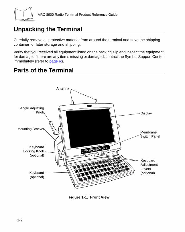
Parts of the Terminal
Figure 1-1. Front View
Display
Keyboard(optional)
Angle AdjustingKnob
Mounting BracketMembrane Switch Panel
KeyboardLocking Knob
(optional)
Keyboard Adjustment Levers (optional)
Antenna
1-2
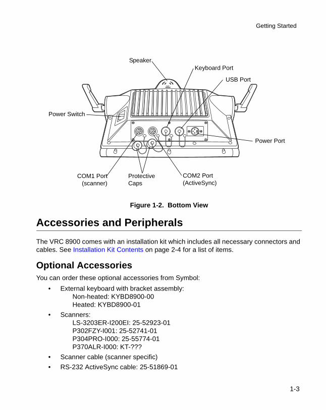
Getting Started
Figure 1-2. Bottom View
Accessories and Peripherals
The VRC 8900 comes with an installation kit which includes all necessary connectors and cables. See Installation Kit Contents on page 2-4 for a list of items.
Optional AccessoriesYou can order these optional accessories from Symbol:
• External keyboard with bracket assembly:Non-heated: KYBD8900-00Heated: KYBD8900-01
• Scanners:LS-3203ER-I200EI: 25-52923-01P302FZY-I001: 25-52741-01P304PRO-I000: 25-55774-01P370ALR-I000: KT-???
• Scanner cable (scanner specific)
• RS-232 ActiveSync cable: 25-51869-01
Power Port
COM2 Port(ActiveSync)
COM1 Port(scanner)
SpeakerKeyboard Port
USB Port
Power Switch
Protective Caps
1-3
VRC 8900 Radio Terminal Product Reference Guide
• USB cable:ActiveSync: 25-56101-01Host: 25-56102-01
• AC universal power supply:Power supply: 50-14001-004Output cable: 50-16002-024Line cord: 23844-00-00
• Filter box (used on gasoline-powered trucks to shut off the terminal when the forklift ignition is turned off, and to filter noise on power cables): FB7900
• Installation Kit (see Installation Kit Contents on page 2-4 for a list of contents)
Note: Use only a Symbol-approved power supply, output rated 12V dc and minimum 9A (p/n 50-14001-004). The power supply is certified to EN60950 with SELV outputs.
Benutzen Sie nur eine Symbol Technologies genehmigt Stromversorgung in den Ausgabe: 12V dc und minimum 9A (p/n 50-14001-004). Die Stromversorgung ist bescheinigt nach EN60950 mit SELV Ausgaben.
Radio CardsVRC 8900 terminals include an internal radio card for use with Symbol Spectrum24 networks. Contact Symbol Technologies for more information on radio cards.
SDKThe Windows® CE SDK for VRC 8900 Terminals contains all necessary software and documentation to assist you in developing applications to run on the VRC 8900.
You will need one or more application development environments (ADEs) from other vendors to develop applications for the VRC 8900, for example Microsoft Visual C++.
1-4
Chapter 2 Installing the Terminal
Introduction
This chapter describes how to install your terminal in a vehicle. There are different installation options depending on the type of vehicle you operate. Read all of the following instructions before you begin.
Caution
A competent engineer must perform the installation in a vehicle. Improper installation can damage your vehicle and/or the VRC 8900.
Do not install the terminal in a location that will affect vehicle safety, drive-ability, or visibility.
WARNING
The VRC 8900 is intended for use on vehicles primarily op-erating indoors, or for fixed indoor installation. The VRC 8900 should not be installed in fixed outdoor locations, or on a vehicle primarily operating outdoors, unless additional environmental protection is provided.
2-1
VRC 8900 Radio Terminal Product Reference Guide
Note: The terminal and bracket must be firmly secured to a surface that can support the terminal’s weight.
Table 2-1 on page 2-4 lists the parts in the installation kit included with your terminal.
Installing Your Terminal
Follow the instructions below to properly install your terminal in a vehicle.
Positioning the Terminal• Determine the best position for the terminal and all the associated components. If
a similar terminal was previously installed, check to see if the position it used is suitable for the VRC 8900.
• Test the installation for at least 30 minutes before installing on another vehicle. Record all details:
• Check that the positions of the terminal and filter box do not obstruct vehicle controls.
• Check that the terminal does not obstruct the driver's view.
• Check the position of the terminal for user comfort over long periods.
• Ensure the filter box is not fitted in a confined space where it may overheat.
Important Fixing InformationAny modification to supplied mountings could cause early failure of the unit/mountings.
• A minimum of four fixing positions must be used.
• All nuts/bolts/end clamps to be checked periodically and tightened if required.
• When installing the unit, care must be taken to ensure that the mounting bracket footprint is fully supported.
• Additional plates may be required to achieve this.
Note:See label on quick release plate for further fixing information.
2-2
Installing the Terminal
Routing Electrical Cables• Establish a neat route for the cable, staying clear of moving parts or hot surfaces
wherever possible.
• Fix the cable to existing cable runs inside the vehicle using cable ties (item 4, Table 2-1), but make sure they are away from any moving or hot surfaces.
• When the cabling must go through a panel, use a suitable gland (item 3, Table 2-1).
• When fixing the conduit or cable on the outside of a vehicle, use P-Clips (item 12, Table 2-1). Either drill and tap the hole or use a nut and bolt to secure the clip.
• Make sure the cable does not have tight bends. The minimum recommended radius is 2.5".
• Solder all fuse holders. DO NOT crimp.
• After soldering the fuse holder, file the solder flat where it comes in contact with the fuse.
• On electric vehicles, take the power from as close to the battery as possible, but not directly from the battery terminals, and not before any main fuse.
• On gasoline, diesel or propane vehicles, take the power from as close to the battery terminals as possible, and avoid using existing wiring.
• All fuses must be as close as possible to the power source.
• If you are unsure of the correct power source, contact the vehicle manufacturer for more information.
2-3
VRC 8900 Radio Terminal Product Reference Guide
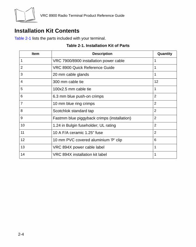
Installation Kit ContentsTable 2-1 lists the parts included with your terminal.
Table 2-1. Installation Kit of Parts
Item Description Quantity
1 VRC 7900/8900 installation power cable 1
2 VRC 8900 Quick Reference Guide 1
3 20 mm cable glands 1
4 300 mm cable tie 12
5 100x2.5 mm cable tie 1
6 6.3 mm blue push-on crimps 2
7 10 mm blue ring crimps 2
8 Scotchlok standard tap 2
9 Fastmm blue piggyback crimps (installation) 2
10 1.24 in Bulgin fuseholder; UL rating 2
11 10 A F/A ceramic 1.25" fuse 2
12 10 mm PVC covered aluminium ’P’ clip 6
13 VRC 894X power cable label 1
14 VRC 894X installation kit label 1
2-4
Installing the Terminal
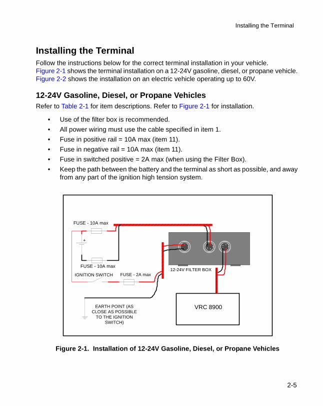
Installing the TerminalFollow the instructions below for the correct terminal installation in your vehicle. Figure 2-1 shows the terminal installation on a 12-24V gasoline, diesel, or propane vehicle. Figure 2-2 shows the installation on an electric vehicle operating up to 60V.
12-24V Gasoline, Diesel, or Propane VehiclesRefer to Table 2-1 for item descriptions. Refer to Figure 2-1 for installation.
• Use of the filter box is recommended.
• All power wiring must use the cable specified in item 1.
• Fuse in positive rail = 10A max (item 11).
• Fuse in negative rail = 10A max (item 11).
• Fuse in switched positive = 2A max (when using the Filter Box).
• Keep the path between the battery and the terminal as short as possible, and away from any part of the ignition high tension system.
Figure 2-1. Installation of 12-24V Gasoline, Diesel, or Propane Vehicles
IGNITION SWITCH FUSE - 2A max
FUSE - 5A max
EARTH POINT (ASCLOSE AS POSSIBLE
TO THE IGNITIONSWITCH)
VRC7900
12-24V FILTER BOXFUSE - 5A max
+
Installation of 12-24V gasoline, diesel or propanevehicles
VRC 8900
FUSE - 10A max
FUSE - 10A max
2-5
VRC 8900 Radio Terminal Product Reference Guide
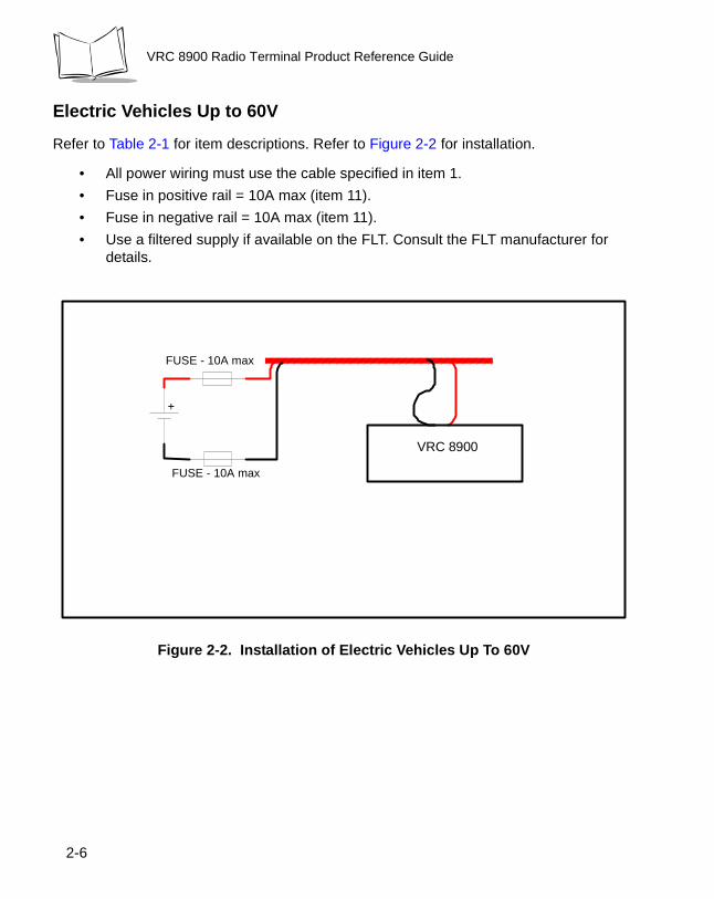
Electric Vehicles Up to 60V
Refer to Table 2-1 for item descriptions. Refer to Figure 2-2 for installation.
• All power wiring must use the cable specified in item 1.
• Fuse in positive rail = 10A max (item 11).
• Fuse in negative rail = 10A max (item 11).
• Use a filtered supply if available on the FLT. Consult the FLT manufacturer for details.
Figure 2-2. Installation of Electric Vehicles Up To 60V
FUSE - 2A max
FUSE - 2A max
VRC7900
+
Installation of electric vehicles over 48V and up to 60V
VRC 8900
FUSE - 10A max
FUSE - 10A max
2-6

Installing the Terminal
Providing Power to the Terminal
WARNING
A Lead Acid battery can leak Hydrogen gas. A spark any-where near the battery can cause it to explode. Always make your final connection to power as far away from the battery as possible. For example, connect the power cable to the battery first, then connect it to the terminal.
Follow the instructions below to connect power to the terminal using the filter box.
Figure 2-3. Connecting Power to Your Terminal
NOTE: - - See the rear label for
voltage input limitations. - Pins 1 & 3 are
connected internally within the supplied cable (Item 1).
3-pin XLR plug viewed externally on VRC7900
1
3
2
1
2
3 4
1
2
2 and 4-pin amphenol connectors viewed externally on filter box.
Filter Box VRC7900 Series
Refer to Table 2-2 for filter box connections.
Refer to Table 2-3 for terminal power connections.
VRC 8900 Series
VRC 8900
Note:See the rear label for voltage input limitations.
Pins 1 & 3 are connected internally within the supplied cable (Item 1).
2-7
VRC 8900 Radio Terminal Product Reference Guide
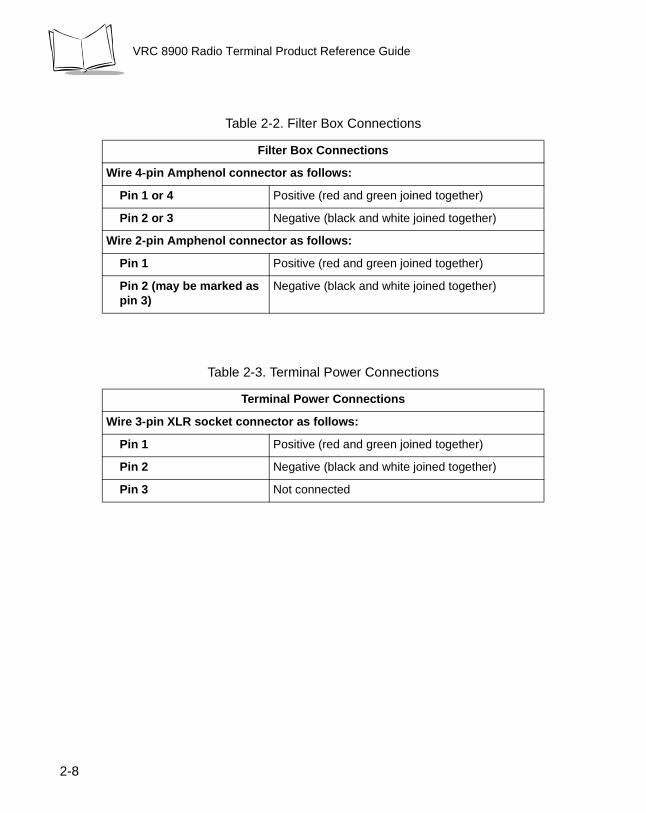
Table 2-2. Filter Box Connections
Filter Box Connections
Wire 4-pin Amphenol connector as follows:
Pin 1 or 4 Positive (red and green joined together)
Pin 2 or 3 Negative (black and white joined together)
Wire 2-pin Amphenol connector as follows:
Pin 1 Positive (red and green joined together)
Pin 2 (may be marked as pin 3)
Negative (black and white joined together)
Table 2-3. Terminal Power Connections
Terminal Power Connections
Wire 3-pin XLR socket connector as follows:
Pin 1 Positive (red and green joined together)
Pin 2 Negative (black and white joined together)
Pin 3 Not connected
2-8
Installing the Terminal
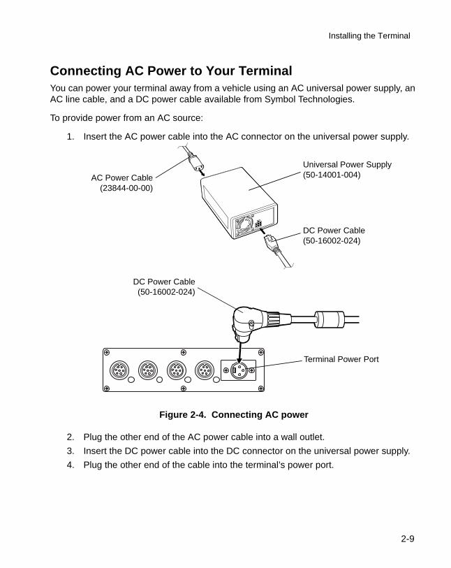
Connecting AC Power to Your TerminalYou can power your terminal away from a vehicle using an AC universal power supply, an AC line cable, and a DC power cable available from Symbol Technologies.
To provide power from an AC source:
1. Insert the AC power cable into the AC connector on the universal power supply.
Figure 2-4. Connecting AC power
2. Plug the other end of the AC power cable into a wall outlet.
3. Insert the DC power cable into the DC connector on the universal power supply.
4. Plug the other end of the cable into the terminal’s power port.
DC Power Cable(50-16002-024)
Universal Power Supply (50-14001-004)AC Power Cable
(23844-00-00)
DC Power Cable(50-16002-024)
Terminal Power Port
2-9

VRC 8900 Radio Terminal Product Reference Guide
Connecting the Filtered DC Power Cable for Electric TrucksThis section describes how to connect and use the filtered DC power cable to provide power to the terminal when mounted on an electric truck.
The cable consists of two ends connected to a central mounting block.
Connecting the Cable1. Disconnect the electric truck battery. Never perform installations on a live electric
truck.
2. Secure the mounting block to the desired location in the truck, using #8 screws. Ensure the DC power connector reaches the terminal and the cable end reaches the DC power source when routed through the truck. Secure the power cable with cable ties.
3. Cut off excess cable at the cable end, and strip 12” off the outer jacket to reveal the screen. Cut the screen back to about 2” and twist the screen strands together.
4. Connect the screen to the truck's chassis. If you cannot find a close connection point, solder an extra length of cable to the screen to extend the connection to the chassis. Use a heat shrink to cover the solder joint.
5. Crimp a ring terminal onto the screen/cable extension and screw the ring terminal into the truck metal work. Or, if a bolt connection exists, attach the ring terminal to this connection (check the connection with a multi-meter to the truck chassis if you’re not sure).
To DC powerconnector
on terminal
Mounting Block
Cable End
2-10
Installing the Terminal
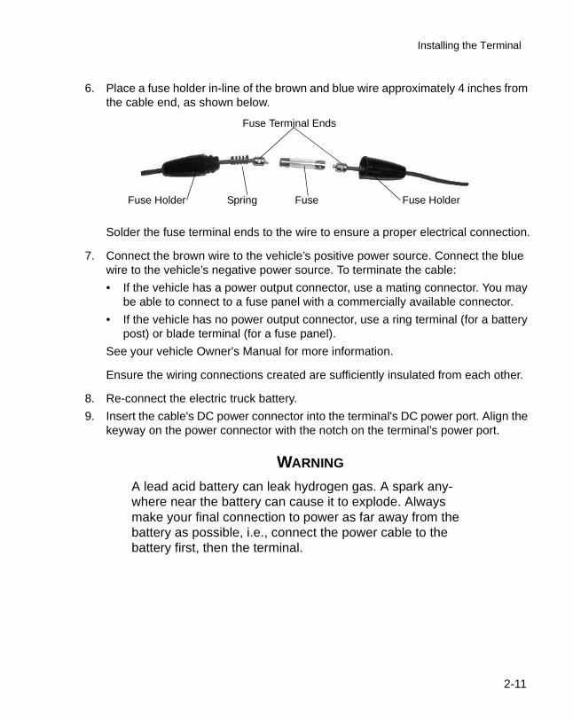
6. Place a fuse holder in-line of the brown and blue wire approximately 4 inches from the cable end, as shown below.
Solder the fuse terminal ends to the wire to ensure a proper electrical connection.
7. Connect the brown wire to the vehicle’s positive power source. Connect the blue wire to the vehicle’s negative power source. To terminate the cable:
• If the vehicle has a power output connector, use a mating connector. You may be able to connect to a fuse panel with a commercially available connector.
• If the vehicle has no power output connector, use a ring terminal (for a battery post) or blade terminal (for a fuse panel).
See your vehicle Owner's Manual for more information.
Ensure the wiring connections created are sufficiently insulated from each other.
8. Re-connect the electric truck battery.
9. Insert the cable's DC power connector into the terminal's DC power port. Align the keyway on the power connector with the notch on the terminal’s power port.
WARNING
A lead acid battery can leak hydrogen gas. A spark any-where near the battery can cause it to explode. Always make your final connection to power as far away from the battery as possible, i.e., connect the power cable to the battery first, then the terminal.
Fuse Holder Fuse HolderSpring Fuse
Fuse Terminal Ends
2-11

VRC 8900 Radio Terminal Product Reference Guide
Caution
Use extreme care when routing and securing this cable from the terminal to the vehicle power source. Hazards associated with improper wiring can be severe. To avoid unintentional contact between the wire and any sharp edges, use proper bushings and clamping where the cable passes through openings. If the wire is subjected to sharp surfaces and excess engine vi-bration, the wiring harness insulation can wear away, causing a short be-tween the bare wire and chassis. This can start a fire.
Installation and the Internal Battery
The VRC8900 has an internal battery that preserves RAM if there is a temporary interruption, disconnection or fluctuation in the main DC or AC power.
The internal battery may be depleted when you first install it. It charges itself from the terminal’s main power supply (DC or AC) when the terminal is running. It also charges when the terminal is in suspend mode (by pressing the Suspend button), but will not charge if power is removed from the terminal.
We recommend that you power on the terminal and allow the internal battery to charge for a minimum of 24 hours before using the terminal. It takes 15 hours to fully charge the internal battery. A fully charged internal battery can maintain data for up to 72 hours if the unit is disconnected from its main power source.
2-12

Installing the Terminal
The Optional Keyboard
The keyboard bracket assembly contains the following items:
• Optional keyboard
• Keyboard bracket
• 4 M4 screws and washers
• Knobs
• Adjustment mechanism
• Side plates
• Bracket knobs
• 5 button-head screws
• 2 flathead screws.
Attaching the Keyboard1. Attach the keyboard brackets to the bottom of the keyboard, using the M4 screws
and washers, as shown below:
Figure 2-5. Attaching the Brackets
Bracket R/H
Bracket L/H
M4 Screws & Washers
2-13
VRC 8900 Radio Terminal Product Reference Guide
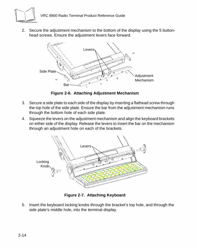
2. Secure the adjustment mechanism to the bottom of the display using the 5 button-head screws. Ensure the adjustment levers face forward.
Figure 2-6. Attaching Adjustment Mechanism
3. Secure a side plate to each side of the display by inserting a flathead screw through the top hole of the side plate. Ensure the bar from the adjustment mechanism runs through the bottom hole of each side plate.
4. Squeeze the levers on the adjustment mechanism and align the keyboard brackets on either side of the display. Release the levers to insert the bar on the mechanism through an adjustment hole on each of the brackets.
Figure 2-7. Attaching Keyboard
5. Insert the keyboard locking knobs through the bracket’s top hole, and through the side plate’s middle hole, into the terminal display.
Adjustment Mechanism
Side Plate
Bar
Levers
LockingKnob
Levers
2-14
Installing the Terminal
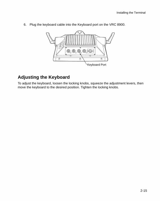
6. Plug the keyboard cable into the Keyboard port on the VRC 8900.
Adjusting the KeyboardTo adjust the keyboard, loosen the locking knobs, squeeze the adjustment levers, then move the keyboard to the desired position. Tighten the locking knobs.
Keyboard Port
2-15

VRC 8900 Radio Terminal Product Reference Guide
2-16

Chapter 3 Software Installation on the Development PC
Introduction
To develop applications to run on the terminal, the Symbol Technologies, Inc. Windows® CE Software Developer’s Kit for VRC 8900 Terminals (SDK) is available. This SDK contains specific software not available in the standard Microsoft Windows® CE SDK.
The minimum system configuration required to install the SDK is:
• IBM-compatible PC with Pentium 150 MHz processor or higher
• Windows® 98, Windows® NT4 with Service Pack 5 or later, or Windows® 2000 (Windows® NT4 or Windows® 2000 required for emulation)
• 24MB RAM for Windows® 98 (48MB recommended), 32MB RAM for Windows® NT4 or Windows® 2000 (48MB recommended)
• 360MB available hard disk space for minimum installation, 720MB available hard disk space for full installation
• CD-ROM drive
• VGA monitor (SVGA recommended)
• Mouse.
Also, be sure the hard drive you are installing to accepts long filenames (larger than the 8.3 filename convention).
Before you install the Symbol Windows CE SDK, install the following tools:
• Microsoft Embedded Visual Tools 3.0. This can be downloaded from www.microsoft.com.
3-1

VRC 8900 Radio Terminal Product Reference Guide
• Windows ActiveSync v3.5 or greater. This can be downloaded from www.microsoft.com.
• Adobe® Acrobat® Reader v 3.0 or greater. Acrobat Reader v 4.0 or greater is recommended.
Symbol Windows CE SDK
The SDK installation program loads the required Windows CE components on the development PC used to create the image files for download to the terminal.
The Symbol Windows CE SDK CD includes:
• Symbol-Platform SDK
• Default CE images
• Device drivers
• Sample code
• HTML Help files.
Installing the SDK on the Development PCThe Windows CE SDK installs through Windows in the directory:
C:\Windows CE Tools\wce300\VRC8900.
Insert the CD in the CD drive on the development PC (drive D: on most computers). The installation program automatically runs. If it does not run:
1. From the Start menu, choose Run.
2. In the open box, type: <drive>:SETUP and press ENTER, where <drive> is the CD- ROM drive.
Note: To ensure the best operation of the SDK, do not change the base path set up in the installation.
Follow the installation prompts.
3-2
Chapter 4 Operating the Terminal
Introduction
This chapter describes how to power, initialize, and operate the terminal.
Powering on the VRC 8900
While the terminal’s processor and display are off, programs or data in the system's memory are retained. Power-up restores the display, and processing continues from where it was before power-down.
Note: Charge the internal battery when powering on the terminal for the first time (refer to Installation and the Internal Battery on page 2-12).
To power on the terminal:
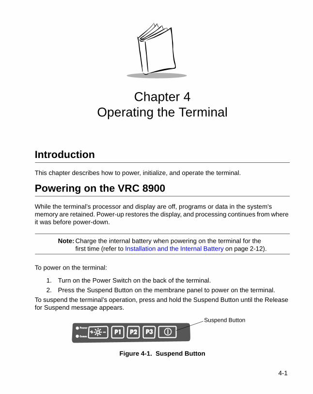
1. Turn on the Power Switch on the back of the terminal.
2. Press the Suspend Button on the membrane panel to power on the terminal.
To suspend the terminal’s operation, press and hold the Suspend Button until the Release for Suspend message appears.
Figure 4-1. Suspend Button
Suspend Button
4-1
VRC 8900 Radio Terminal Product Reference Guide
The network configuration screen displays. If desired, configure the terminal for wireless communication (refer to Chapter 5, Spectrum24 Network Configuration).
Note: The network configuration screen appears the first time you start the terminal after power is removed, but not on subsequent warm or cold boots.
To suspend the terminal’s operation, press the Suspend button. All DRAM and Flash data is preserved, so the applications running continue after suspension. Press the Suspend button again to power up the terminal. This power-up process takes about 12 seconds.
The power is on at all times if the terminal is hard wired to the vehicle battery.
Booting the Terminal
Performing a Warm BootA warm boot restarts the operating system, closes all running applications, and preserves the saved data in RAM. In the Windows CE environment, the working registry is replaced by the latest saved copy of the registry.
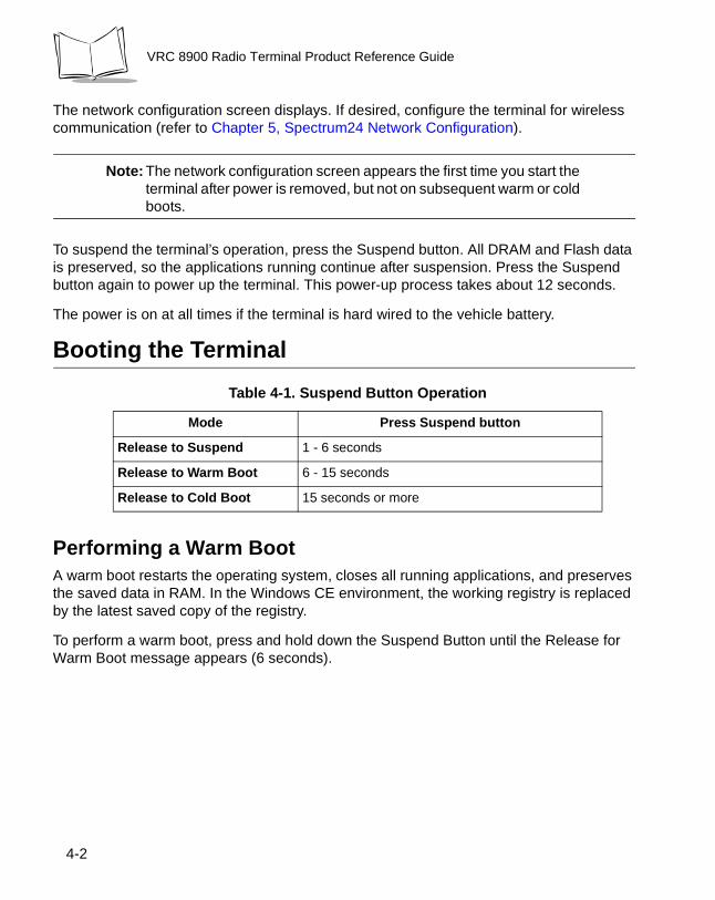
To perform a warm boot, press and hold down the Suspend Button until the Release for Warm Boot message appears (6 seconds).
Table 4-1. Suspend Button Operation
Mode Press Suspend button
Release to Suspend 1 - 6 seconds
Release to Warm Boot 6 - 15 seconds
Release to Cold Boot 15 seconds or more
4-2
Operating the Terminal
Performing a Cold BootA cold boot restarts the terminal. In the Windows CE environment, the working registry is replaced by the latest saved copy of the registry. All information in DRAM is discarded (data in Flash is maintained).
There are two ways to perform a cold boot:
• Press and hold the Suspend Button until the Release for Cold Boot message appears (15 seconds).
• Turn off the Power Switch on the back of the terminal, then turn it on again, and then press the Suspend button.
Methods of SuspensionTerminal operation can be suspended in four ways:
• Manual suspension: the operator presses the Suspend button when the terminal is on, or taps Start, then presses the Suspend button.
• Program-dependent suspension: the application requests a suspend via an API call.
• Critical suspension: the power supply is removed.
4-3
VRC 8900 Radio Terminal Product Reference Guide
Programmable (“P”) Keys
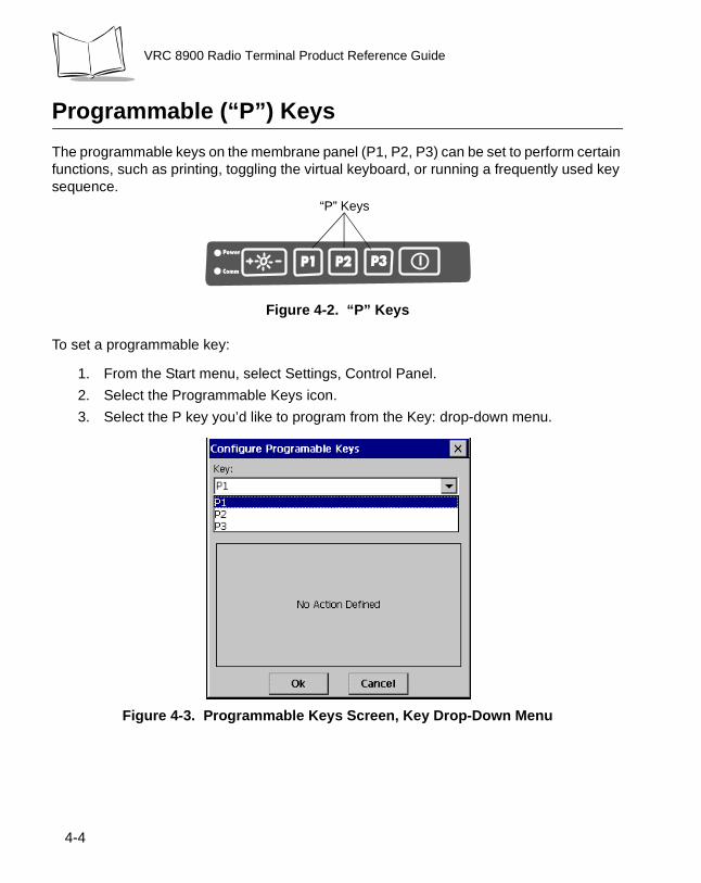
The programmable keys on the membrane panel (P1, P2, P3) can be set to perform certain functions, such as printing, toggling the virtual keyboard, or running a frequently used key sequence.
Figure 4-2. “P” Keys
To set a programmable key:
1. From the Start menu, select Settings, Control Panel.
2. Select the Programmable Keys icon.
3. Select the P key you’d like to program from the Key: drop-down menu.
Figure 4-3. Programmable Keys Screen, Key Drop-Down Menu
“P” Keys
4-4
Operating the Terminal
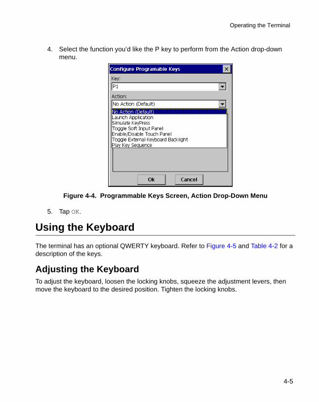
4. Select the function you’d like the P key to perform from the Action drop-down menu.
Figure 4-4. Programmable Keys Screen, Action Drop-Down Menu
5. Tap OK.
Using the Keyboard
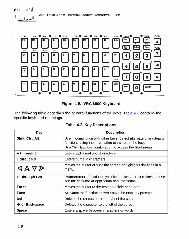
The terminal has an optional QWERTY keyboard. Refer to Figure 4-5 and Table 4-2 for a description of the keys.
Adjusting the KeyboardTo adjust the keyboard, loosen the locking knobs, squeeze the adjustment levers, then move the keyboard to the desired position. Tighten the locking knobs.
4-5
VRC 8900 Radio Terminal Product Reference Guide
Figure 4-5. VRC 8900 Keyboard
The following table describes the general functions of the keys. Table 4-3 contains the specific keyboard mappings.
Table 4-2. Key Descriptions
Key Description
Shift, Ctrl, Alt Use in conjunction with other keys. Select alternate characters or functions using the information at the top of the keys.Use Ctrl - Esc key combination to access the Start menu.
A through Z Enters alpha and text characters.
0 through 9 Enters numeric characters.
Moves the cursor around the screen or highlights the lines in a menu.
F1 through F24 Programmable function keys. The application determines the use; see the software or application documentation.
Enter Moves the cursor to the next data field or screen.
Func Activates the function shown above the next key pressed.
Del Deletes the character to the right of the cursor.
� or Backspace Deletes the character to the left of the cursor.
Space Enters a space between characters or words.
4-6

Operating the Terminal
Table 4-3. Keyboard Mappings
VRC 8900 Key Scan Code Virtual Key Func + (Unicode) Shift + (Unicode)
z 5a ~ Z
x 58 ; X
c 43 @ C
v 56 $ V
b 42 % B
n 4e ] N
m 4d ^ M
a 41 > A
s 53 Shell lock S
d 44 < D
f 46 , F
g 47 | G
h 48 \ H
j 4a { J
k 4b } K
l 4c [ L
q 51 F21 Q
w 57 F22 W
e 45 F23 E
r 52 F24 R
t 54 = T
y 59 � Y
u 55 � U
i 49 £ I
o 4f “ O
4-7
VRC 8900 Radio Terminal Product Reference Guide
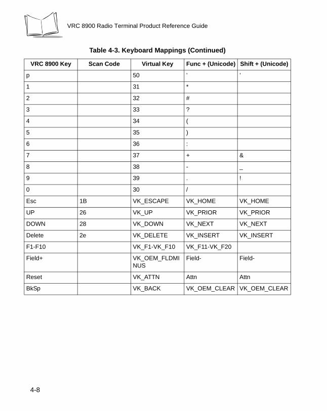
p 50 ’ ’
1 31 *
2 32 #
3 33 ?
4 34 (
5 35 )
6 36 :
7 37 + &
8 38 - _
9 39 . !
0 30 /
Esc 1B VK_ESCAPE VK_HOME VK_HOME
UP 26 VK_UP VK_PRIOR VK_PRIOR
DOWN 28 VK_DOWN VK_NEXT VK_NEXT
Delete 2e VK_DELETE VK_INSERT VK_INSERT
F1-F10 VK_F1-VK_F10 VK_F11-VK_F20
Field+ VK_OEM_FLDMINUS
Field- Field-
Reset VK_ATTN Attn Attn
BkSp VK_BACK VK_OEM_CLEAR VK_OEM_CLEAR
Table 4-3. Keyboard Mappings (Continued)
VRC 8900 Key Scan Code Virtual Key Func + (Unicode) Shift + (Unicode)
4-8
Operating the Terminal
Locking the Desktop
You can lock the desktop of the VRC 8900 to hide icons that contain configuration information such as terminal and network settings. When you lock the desktop, only the working applications display.
If you don’t have the optional keyboard, use the virtual keyboard on the VRC 8900 to perform the following key sequences.
• Press the Func + “S” keys to display the password screen. Enter a password and tap OK. The terminal displays only the working applications.
• Press the Func + “S” keys again to display the password screen. Enter your password again and all icons display on the screen.
Calibrating the Screen
Calibrating Using the DisplayThis section describes how to calibrate your terminal so the cursor on the touch screen aligns with the tip of your stylus. If the current calibration does not allow for easy touch screen input or you want to recalibrate the screen at any time, refer to Calibrating Using the Keyboard on page 4-12.
To calibrate your terminal:
1. If you are using the default registry, go to step 5. Otherwise, proceed with step 2.
2. Tap the Start menu.
4-9

VRC 8900 Radio Terminal Product Reference Guide
3. Tap Settings, then Control Panel. The Control Panel screen displays.
Figure 4-6. Control Panel Screen
4-10
Operating the Terminal
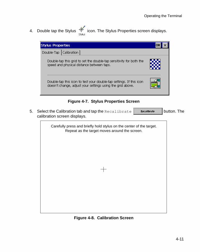
4. Double tap the Stylus icon. The Stylus Properties screen displays.
Figure 4-7. Stylus Properties Screen
5. Select the Calibration tab and tap the Recalibrate button. The calibration screen displays.
Figure 4-8. Calibration Screen
Carefully press and briefly hold stylus on the center of the target. Repeat as the target moves around the screen.
4-11

VRC 8900 Radio Terminal Product Reference Guide
6. As the screen instructs, carefully press and briefly hold the stylus on the center of each target that appears on the screen. Repeat as the target moves around the screen.
7. Tap the screen to accept the new calibration.
Note: If the digitizer fails to respond, call the Symbol Support Center for assistance.
Calibrating Using the KeyboardIf the present calibration does not allow you to use the touch screen, use the keyboard to calibrate:
1. Press Ctrl + Esc keys to access the Start menu.
2. Using the arrow keys, select Settings, then Control Panel.
4-12
Operating the Terminal
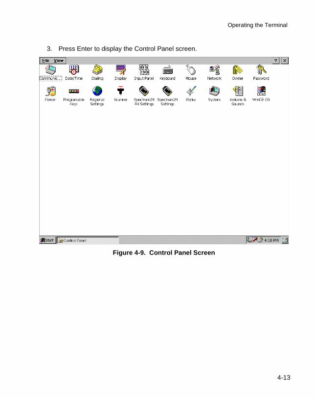
3. Press Enter to display the Control Panel screen.
Figure 4-9. Control Panel Screen
4-13
VRC 8900 Radio Terminal Product Reference Guide
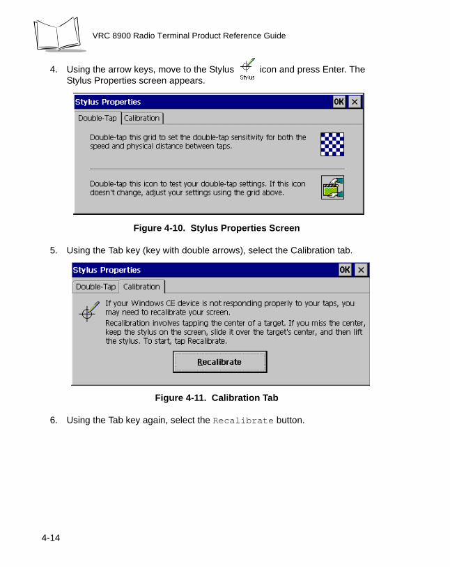
4. Using the arrow keys, move to the Stylus icon and press Enter. TheStylus Properties screen appears.
Figure 4-10. Stylus Properties Screen
5. Using the Tab key (key with double arrows), select the Calibration tab.
Figure 4-11. Calibration Tab
6. Using the Tab key again, select the Recalibrate button.
4-14
Operating the Terminal
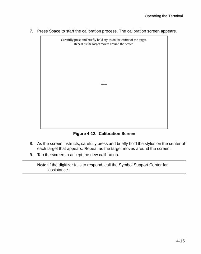
7. Press Space to start the calibration process. The calibration screen appears.
Figure 4-12. Calibration Screen
8. As the screen instructs, carefully press and briefly hold the stylus on the center of each target that appears. Repeat as the target moves around the screen.
9. Tap the screen to accept the new calibration.
Note: If the digitizer fails to respond, call the Symbol Support Center for assistance.
Carefully press and briefly hold stylus on the center of the target. Repeat as the target moves around the screen.
4-15
VRC 8900 Radio Terminal Product Reference Guide
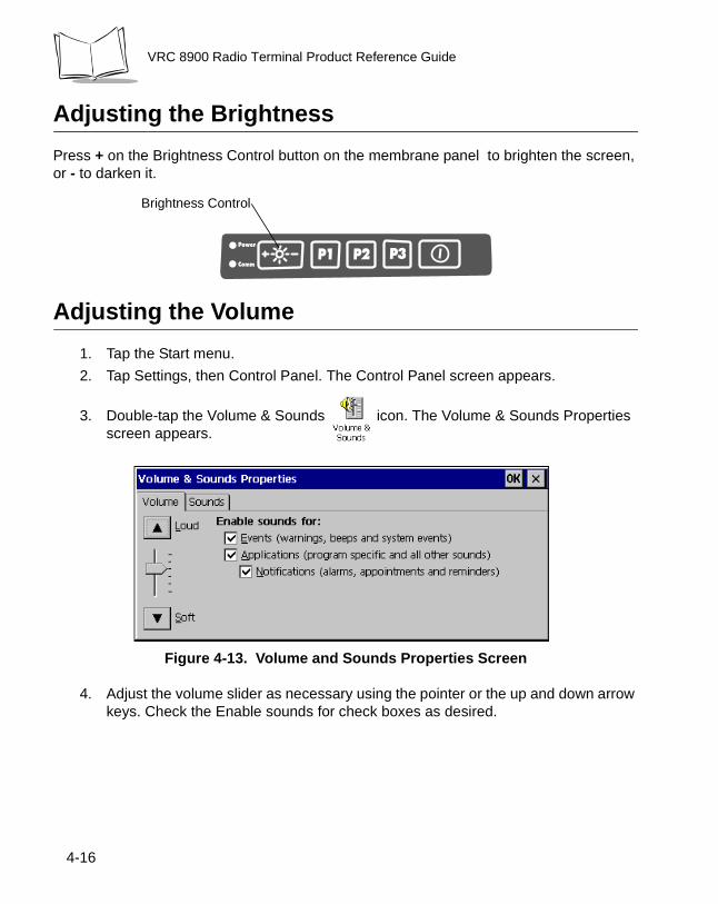
Adjusting the Brightness
Press + on the Brightness Control button on the membrane panel to brighten the screen, or - to darken it.
Adjusting the Volume
1. Tap the Start menu.
2. Tap Settings, then Control Panel. The Control Panel screen appears.
3. Double-tap the Volume & Sounds icon. The Volume & Sounds Properties screen appears.
Figure 4-13. Volume and Sounds Properties Screen
4. Adjust the volume slider as necessary using the pointer or the up and down arrow keys. Check the Enable sounds for check boxes as desired.
Brightness Control
4-16
Operating the Terminal
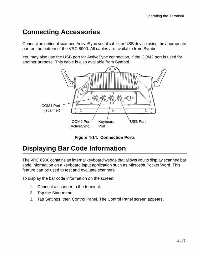
Connecting Accessories
Connect an optional scanner, ActiveSync serial cable, or USB device using the appropriate port on the bottom of the VRC 8900. All cables are available from Symbol.
You may also use the USB port for ActiveSync connection, if the COM2 port is used for another purpose. This cable is also available from Symbol.
Figure 4-14. Connection Ports
Displaying Bar Code Information
The VRC 8900 contains an internal keyboard wedge that allows you to display scanned bar code information on a keyboard input application such as Microsoft Pocket Word. This feature can be used to test and evaluate scanners.
To display the bar code information on the screen:
1. Connect a scanner to the terminal.
2. Tap the Start menu.
3. Tap Settings, then Control Panel. The Control Panel screen appears.
COM2 Port(ActiveSync)
COM1 Port(scanner)
Keyboard Port
USB Port
4-17
VRC 8900 Radio Terminal Product Reference Guide
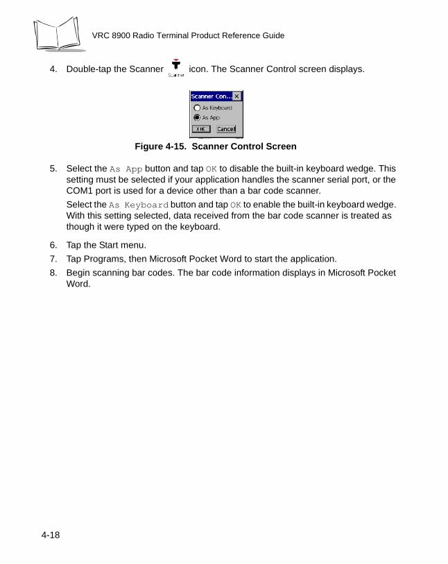
4. Double-tap the Scanner icon. The Scanner Control screen displays.
Figure 4-15. Scanner Control Screen
5. Select the As App button and tap OK to disable the built-in keyboard wedge. This setting must be selected if your application handles the scanner serial port, or the COM1 port is used for a device other than a bar code scanner.
Select the As Keyboard button and tap OK to enable the built-in keyboard wedge. With this setting selected, data received from the bar code scanner is treated as though it were typed on the keyboard.
6. Tap the Start menu.
7. Tap Programs, then Microsoft Pocket Word to start the application.
8. Begin scanning bar codes. The bar code information displays in Microsoft Pocket Word.
4-18
Operating the Terminal
Saving Files and Allocating Memory
The terminal uses a Flash file system and a DRAM file system to save files, run applications, and allocate memory as necessary.
Flash File SystemThe terminal contains 32MB of non-volatile Flash memory; 16MB reserved for Windows CE operating system; 15MB for storage of programs and program files (Flash file system); 256KB for storing the boot code. The remaining space is used to store the registry.
Permanently save your files and programs to Flash by moving them to the following folders in ‘\FlashFx Disk\’:
• \ActiveX - ActiveX controls placed in this folder are registered on start up.
• \CopyToRam - the following folders are available:
• \Root - applications or files placed in this folder are copied to the root directory.• \Startup - applications placed in this folder are permanently stored in Flash but
copied to DRAM and executed on start up.
• \System - applications or data placed in this folder are permanently stored in Flash but copied to the \Windows folder in DRAM on start up.
• \User - user application files.
DRAM File SystemThe terminal contains 32MB of DRAM backed up by the internal battery. The Windows CE operating system, along with applications in the \CopyToRam directory, is copied from Flash to DRAM and runs from DRAM when you boot the terminal.
The DRAM contains the desktop, user settings, and registry. If this information is lost due to a cold boot or complete discharge of the internal battery, default data is loaded from Flash on the next start up.
To boot up using the default registry in RAM:
1. With the terminal in suspend mode, hold down the P1 + P3 + Suspend buttons.
2. Release only the Suspend button when the terminal powers up.
3. Release P1 + P3 when the Boot Loader menu displays.
4. Select Use Default Registry from the menu.
4-19
VRC 8900 Radio Terminal Product Reference Guide
You can change the allocation of remaining memory for programs and storage using the Control Panel. Open the System menu and tap the Memory tab. The recommended setting is 50% of memory available for programs and 50% of memory available for storage. If your applications require more program space, more storage space, or you receive a memory warning, adjust the percentages as necessary.
4-20
Chapter 5 Spectrum24 Network Configuration
Introduction
In order to use Symbol’s Spectrum24 wireless LAN on the VRC 8900 terminals, the terminal must be properly configured with the correct ESS ID and other network entries. This chapter describes how to configure your terminal on the Spectrum24 wireless network.
Configuring Your 2 Mbps Terminal
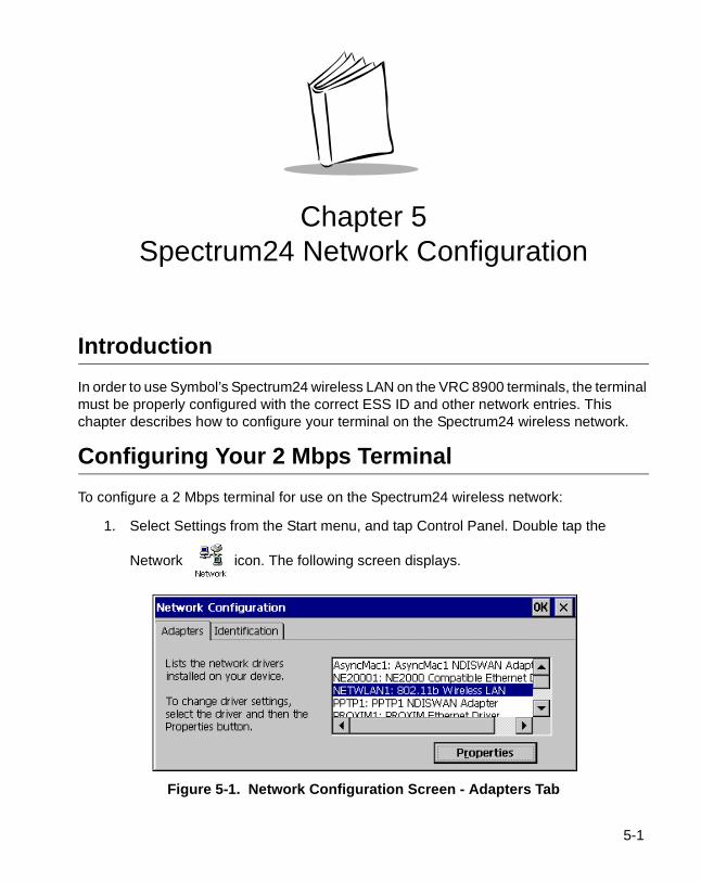
To configure a 2 Mbps terminal for use on the Spectrum24 wireless network:
1. Select Settings from the Start menu, and tap Control Panel. Double tap the
Network icon. The following screen displays.
Figure 5-1. Network Configuration Screen - Adapters Tab
5-1
5
VRC 8900 Radio Terminal Product Reference Guide
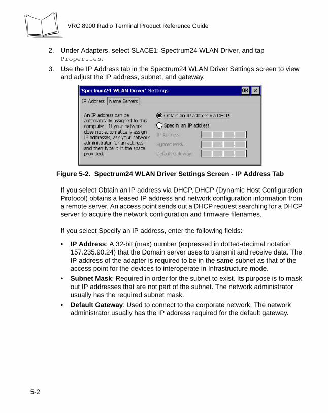
2. Under Adapters, select SLACE1: Spectrum24 WLAN Driver, and tap Properties.
3. Use the IP Address tab in the Spectrum24 WLAN Driver Settings screen to view and adjust the IP address, subnet, and gateway.
Figure 5-2. Spectrum24 WLAN Driver Settings Screen - IP Address Tab
If you select Obtain an IP address via DHCP, DHCP (Dynamic Host Configuration Protocol) obtains a leased IP address and network configuration information from a remote server. An access point sends out a DHCP request searching for a DHCP server to acquire the network configuration and firmware filenames.
If you select Specify an IP address, enter the following fields:
• IP Address: A 32-bit (max) number (expressed in dotted-decimal notation 157.235.90.24) that the Domain server uses to transmit and receive data. The IP address of the adapter is required to be in the same subnet as that of the access point for the devices to interoperate in Infrastructure mode.
• Subnet Mask: Required in order for the subnet to exist. Its purpose is to mask out IP addresses that are not part of the subnet. The network administrator usually has the required subnet mask.
• Default Gateway: Used to connect to the corporate network. The network administrator usually has the IP address required for the default gateway.
-2
Spectrum24 Network Configuration
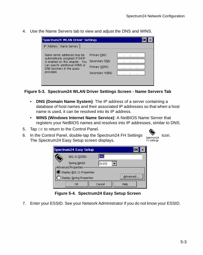
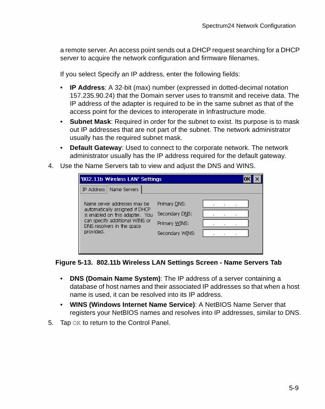
4. Use the Name Servers tab to view and adjust the DNS and WINS.
Figure 5-3. Spectrum24 WLAN Driver Settings Screen - Name Servers Tab
• DNS (Domain Name System): The IP address of a server containing a database of host names and their associated IP addresses so that when a host name is used, it can be resolved into its IP address.
• WINS (Windows Internet Name Service): A NetBIOS Name Server that registers your NetBIOS names and resolves into IP addresses, similar to DNS.
5. Tap OK to return to the Control Panel.
6. In the Control Panel, double-tap the Spectrum24 FH Settings icon.The Spectrum24 Easy Setup screen displays.
Figure 5-4. Spectrum24 Easy Setup Screen
7. Enter your ESSID. See your Network Administrator if you do not know your ESSID.
5-3
5
VRC 8900 Radio Terminal Product Reference Guide
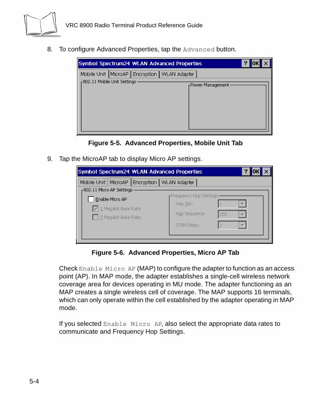
8. To configure Advanced Properties, tap the Advanced button.
Figure 5-5. Advanced Properties, Mobile Unit Tab
9. Tap the MicroAP tab to display Micro AP settings.
Figure 5-6. Advanced Properties, Micro AP Tab
Check Enable Micro AP (MAP) to configure the adapter to function as an access point (AP). In MAP mode, the adapter establishes a single-cell wireless network coverage area for devices operating in MU mode. The adapter functioning as an MAP creates a single wireless cell of coverage. The MAP supports 16 terminals, which can only operate within the cell established by the adapter operating in MAP mode.
If you selected Enable Micro AP, also select the appropriate data rates to communicate and Frequency Hop Settings.
-4
Spectrum24 Network Configuration
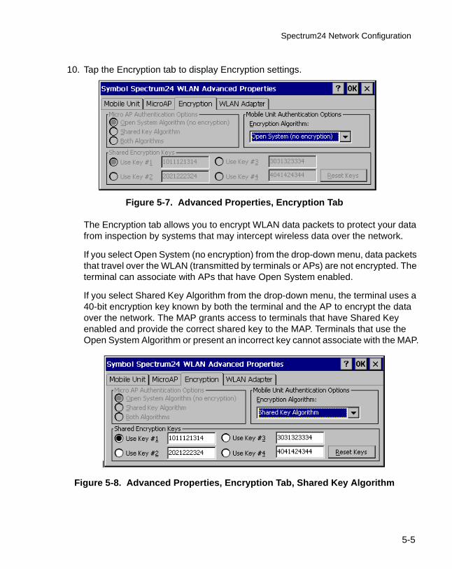
10. Tap the Encryption tab to display Encryption settings.
Figure 5-7. Advanced Properties, Encryption Tab
The Encryption tab allows you to encrypt WLAN data packets to protect your data from inspection by systems that may intercept wireless data over the network.
If you select Open System (no encryption) from the drop-down menu, data packets that travel over the WLAN (transmitted by terminals or APs) are not encrypted. The terminal can associate with APs that have Open System enabled.
If you select Shared Key Algorithm from the drop-down menu, the terminal uses a 40-bit encryption key known by both the terminal and the AP to encrypt the data over the network. The MAP grants access to terminals that have Shared Key enabled and provide the correct shared key to the MAP. Terminals that use the Open System Algorithm or present an incorrect key cannot associate with the MAP.
Figure 5-8. Advanced Properties, Encryption Tab, Shared Key Algorithm
5-5
VRC 8900 Radio Terminal Product Reference Guide
Shared Encryption Keys are the 40-bit values used by the terminal and the AP to encrypt the wireless data packets. To change the default values, enter 10 hexadecimal digits for each of the four keys. Click on the key to use, or press the Reset Keys button to reset the keys back to the default values.
The Shared Encryption Key must match that of the access point in order for the terminal to associate.
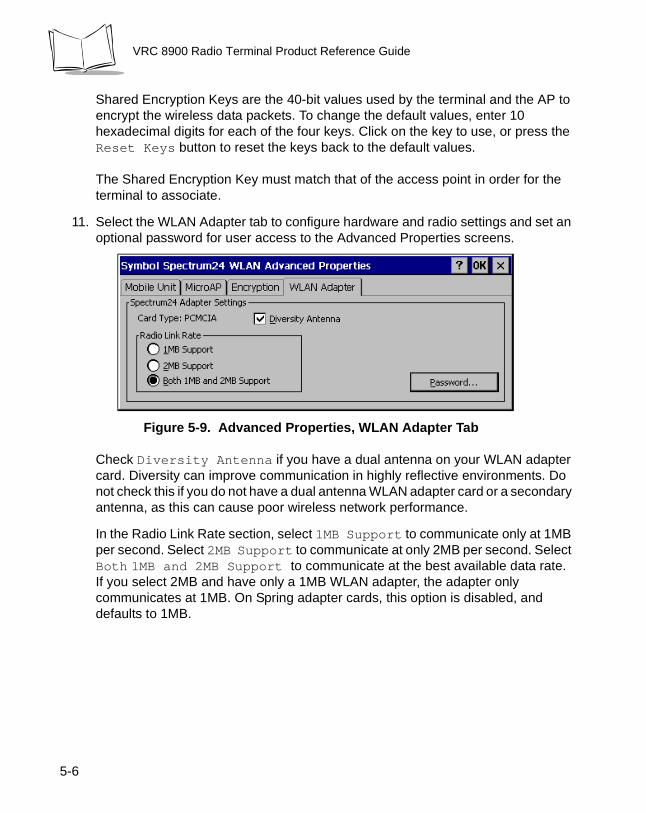
11. Select the WLAN Adapter tab to configure hardware and radio settings and set an optional password for user access to the Advanced Properties screens.
Figure 5-9. Advanced Properties, WLAN Adapter Tab
Check Diversity Antenna if you have a dual antenna on your WLAN adapter card. Diversity can improve communication in highly reflective environments. Do not check this if you do not have a dual antenna WLAN adapter card or a secondary antenna, as this can cause poor wireless network performance.
In the Radio Link Rate section, select 1MB Support to communicate only at 1MB per second. Select 2MB Support to communicate at only 2MB per second. Select Both 1MB and 2MB Support to communicate at the best available data rate. If you select 2MB and have only a 1MB WLAN adapter, the adapter only communicates at 1MB. On Spring adapter cards, this option is disabled, and defaults to 1MB.
5-6

Spectrum24 Network Configuration
To create a password, tap Password.
Figure 5-10. Password Screen
Enter a case-sensitive password (10 characters maximum) in the New Password field and the Confirm New Password field, and select OK. This enables a password screen to appear when Advanced is selected from the Spectrum24 Easy Setup screen.
To disable the password, enter the current password in the Current Password field, and leave the New Password and Confirm New fields blank.
5-7
VRC 8900 Radio Terminal Product Reference Guide
Configuring Your 11 Mbps Terminal
To configure the terminal for use on the Spectrum24 wireless network:
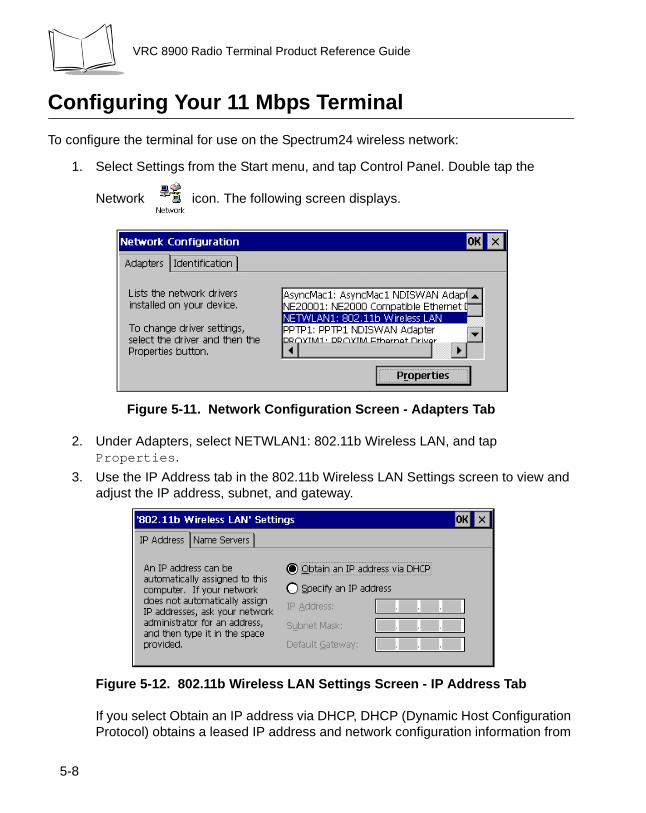
1. Select Settings from the Start menu, and tap Control Panel. Double tap the
Network icon. The following screen displays.
Figure 5-11. Network Configuration Screen - Adapters Tab
2. Under Adapters, select NETWLAN1: 802.11b Wireless LAN, and tap Properties.
3. Use the IP Address tab in the 802.11b Wireless LAN Settings screen to view and adjust the IP address, subnet, and gateway.
Figure 5-12. 802.11b Wireless LAN Settings Screen - IP Address Tab
If you select Obtain an IP address via DHCP, DHCP (Dynamic Host Configuration Protocol) obtains a leased IP address and network configuration information from
5-8
Spectrum24 Network Configuration
a remote server. An access point sends out a DHCP request searching for a DHCP server to acquire the network configuration and firmware filenames.
If you select Specify an IP address, enter the following fields:
• IP Address: A 32-bit (max) number (expressed in dotted-decimal notation 157.235.90.24) that the Domain server uses to transmit and receive data. The IP address of the adapter is required to be in the same subnet as that of the access point for the devices to interoperate in Infrastructure mode.
• Subnet Mask: Required in order for the subnet to exist. Its purpose is to mask out IP addresses that are not part of the subnet. The network administrator usually has the required subnet mask.
• Default Gateway: Used to connect to the corporate network. The network administrator usually has the IP address required for the default gateway.
4. Use the Name Servers tab to view and adjust the DNS and WINS.
Figure 5-13. 802.11b Wireless LAN Settings Screen - Name Servers Tab
• DNS (Domain Name System): The IP address of a server containing a database of host names and their associated IP addresses so that when a host name is used, it can be resolved into its IP address.
• WINS (Windows Internet Name Service): A NetBIOS Name Server that registers your NetBIOS names and resolves into IP addresses, similar to DNS.
5. Tap OK to return to the Control Panel.
5-9
VRC 8900 Radio Terminal Product Reference Guide
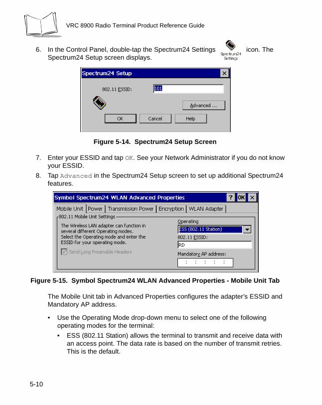
6. In the Control Panel, double-tap the Spectrum24 Settings icon. The Spectrum24 Setup screen displays.
Figure 5-14. Spectrum24 Setup Screen
7. Enter your ESSID and tap OK. See your Network Administrator if you do not know your ESSID.
8. Tap Advanced in the Spectrum24 Setup screen to set up additional Spectrum24 features.
Figure 5-15. Symbol Spectrum24 WLAN Advanced Properties - Mobile Unit Tab
The Mobile Unit tab in Advanced Properties configures the adapter’s ESSID and Mandatory AP address.
• Use the Operating Mode drop-down menu to select one of the following operating modes for the terminal:
• ESS (802.11 Station) allows the terminal to transmit and receive data with an access point. The data rate is based on the number of transmit retries. This is the default.
5-10
Spectrum24 Network Configuration
• Pseudo IBSS (Proprietary Ad Hoc) allows the highest throughput in an IBSS network for terminal testing. Pseudo IBSS does not support PSP terminals and does not use beacons or authentication. Each terminal must be on the same channel. If you select this option, the Signal and Peers tabs are no longer available. Pseudo IBSS is not recommended as a normal operational mode or for terminals operating on battery power.
• IBSS (802.11 Ad Hoc) enables terminals to form their own local network where they can communicate peer-to-peer without access points. Use IBSS to create networks within established cells. Terminals take turns generating beacons and handling probe responses. The terminal starting the IBSS network (i.e., the first terminal transmitting a beacon) determines the channel number and data rate used within the network.
• Enter a 32-character (maximum) case-sensitive ESS ID (802.11 Extended Service Set Identifier) in the 802.11 ESSID field to identify the wireless local area network. This identifier must match the ESSID in the 802.11 access point(s) on your network in order for your WLAN adapter to communicate with the access point(s). If you don't know your ESSID, ask your IS department personnel for assistance.
• The Mandatory AP address is the IEEE MAC address of the access point (AP) where the adapter must associate. The adapter only associates to this access point when communicating on the network.
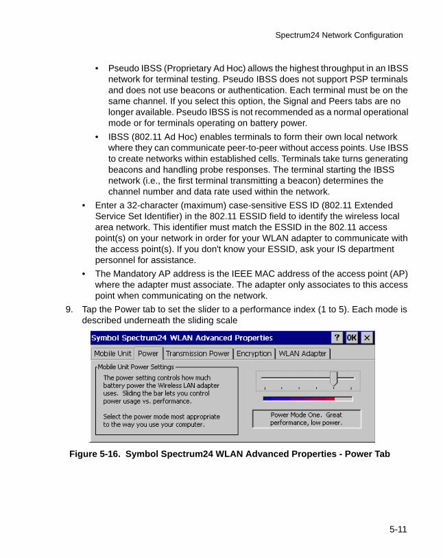
9. Tap the Power tab to set the slider to a performance index (1 to 5). Each mode is described underneath the sliding scale
Figure 5-16. Symbol Spectrum24 WLAN Advanced Properties - Power Tab
5-11
VRC 8900 Radio Terminal Product Reference Guide
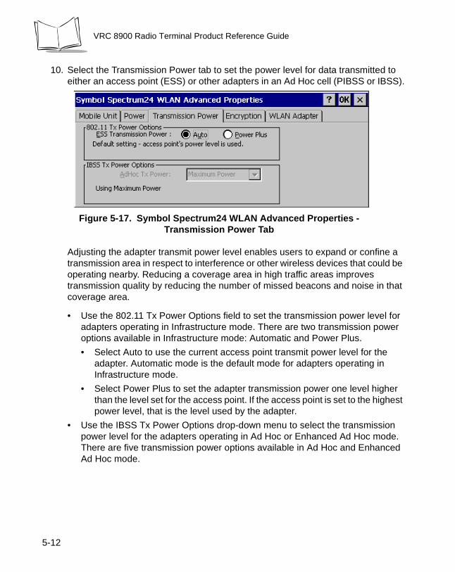
10. Select the Transmission Power tab to set the power level for data transmitted to either an access point (ESS) or other adapters in an Ad Hoc cell (PIBSS or IBSS).
Figure 5-17. Symbol Spectrum24 WLAN Advanced Properties - Transmission Power Tab
Adjusting the adapter transmit power level enables users to expand or confine a transmission area in respect to interference or other wireless devices that could be operating nearby. Reducing a coverage area in high traffic areas improves transmission quality by reducing the number of missed beacons and noise in that coverage area.
• Use the 802.11 Tx Power Options field to set the transmission power level for adapters operating in Infrastructure mode. There are two transmission power options available in Infrastructure mode: Automatic and Power Plus.
• Select Auto to use the current access point transmit power level for the adapter. Automatic mode is the default mode for adapters operating in Infrastructure mode.
• Select Power Plus to set the adapter transmission power one level higher than the level set for the access point. If the access point is set to the highest power level, that is the level used by the adapter.
• Use the IBSS Tx Power Options drop-down menu to select the transmission power level for the adapters operating in Ad Hoc or Enhanced Ad Hoc mode. There are five transmission power options available in Ad Hoc and Enhanced Ad Hoc mode.
5-12

Spectrum24 Network Configuration
• Select Maximum power to set the adapter to the highest transmission power level. Select Maximum power when operating in highly reflective environments and areas where other devices could be operating nearby, or when attempting to communicate with devices at the outer edge of a coverage area.
• Choose 50% power to set the adapter to a transmit power level that is half of the maximum power level.
• Specify 25% power to set the adapter to a transmit power level that is half of the 50% power level.
• Select 10% power to set the adapter to a transmit power level that is a little less than half of the 25% power level.
• Choose Minimum power to set the adapter to the lowest transmission power level. Use the minimum power level when communicating with other devices in very close proximity, or in instances where little or no radio interference from other devices is anticipated.
11. Use the Encryption tab in Advanced Properties to control encryption options. This allows you to encrypt WLAN data packets to protect your data from inspection by systems that may intercept wireless data over the network.
Figure 5-18. Symbol Spectrum24 WLAN Advanced Properties - Encryption Tab
Select an Encryption Algorithm matching the security established in your network. The AP and the terminal’s adapter must use the same encryption algorithm:
• The Open System does not encrypt any of the data packets that travel over the WLAN, meaning the data packets transmitted by terminals or APs are not encrypted. Select this if no security is needed on the network.
5-13
VRC 8900 Radio Terminal Product Reference Guide
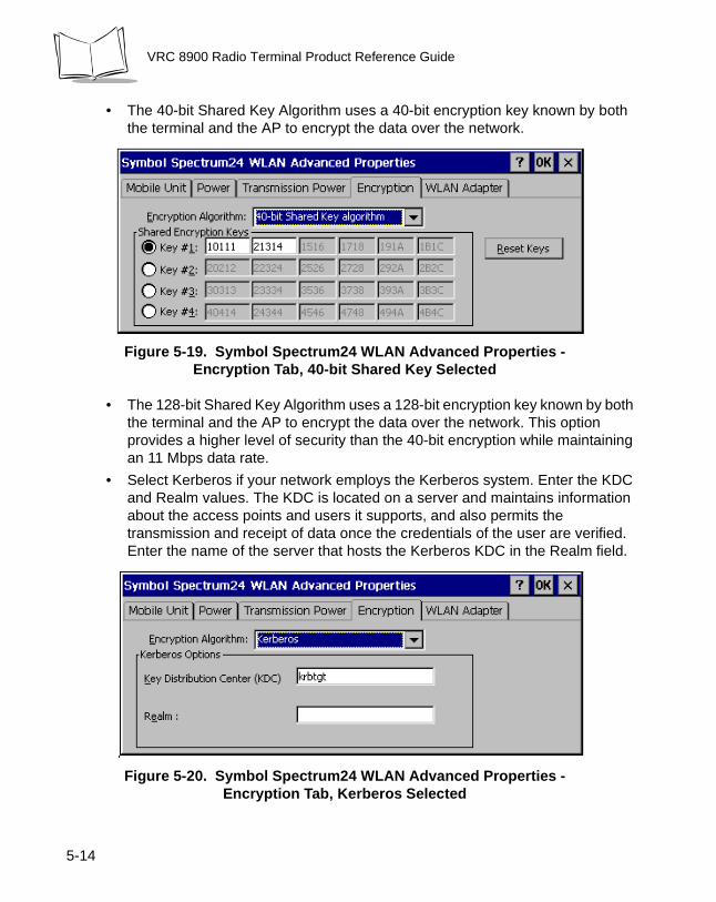
• The 40-bit Shared Key Algorithm uses a 40-bit encryption key known by both the terminal and the AP to encrypt the data over the network.
Figure 5-19. Symbol Spectrum24 WLAN Advanced Properties - Encryption Tab, 40-bit Shared Key Selected
• The 128-bit Shared Key Algorithm uses a 128-bit encryption key known by both the terminal and the AP to encrypt the data over the network. This option provides a higher level of security than the 40-bit encryption while maintaining an 11 Mbps data rate.
• Select Kerberos if your network employs the Kerberos system. Enter the KDC and Realm values. The KDC is located on a server and maintains information about the access points and users it supports, and also permits the transmission and receipt of data once the credentials of the user are verified. Enter the name of the server that hosts the Kerberos KDC in the Realm field.
Figure 5-20. Symbol Spectrum24 WLAN Advanced Properties - Encryption Tab, Kerberos Selected
5-14
Spectrum24 Network Configuration
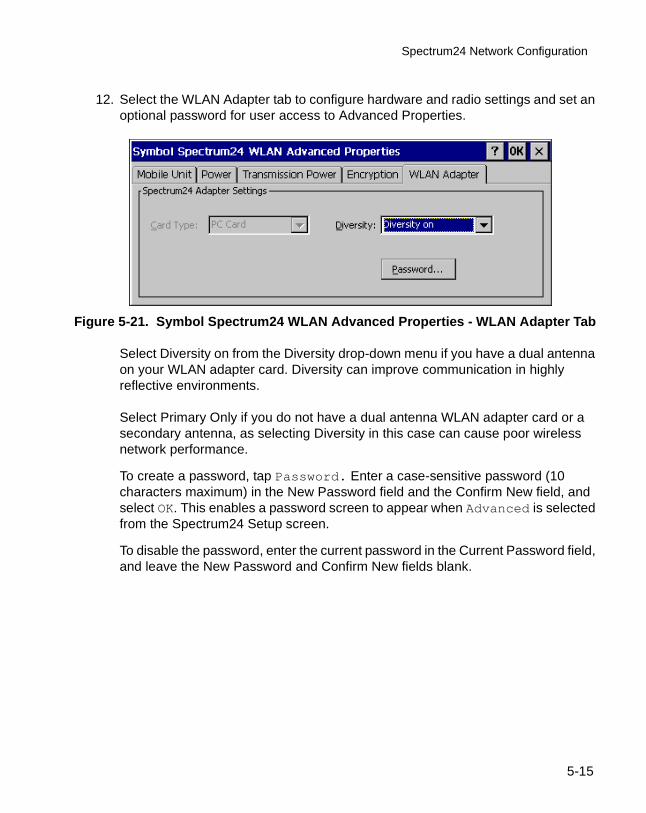
12. Select the WLAN Adapter tab to configure hardware and radio settings and set an optional password for user access to Advanced Properties.
Figure 5-21. Symbol Spectrum24 WLAN Advanced Properties - WLAN Adapter Tab
Select Diversity on from the Diversity drop-down menu if you have a dual antenna on your WLAN adapter card. Diversity can improve communication in highly reflective environments.
Select Primary Only if you do not have a dual antenna WLAN adapter card or a secondary antenna, as selecting Diversity in this case can cause poor wireless network performance.
To create a password, tap Password. Enter a case-sensitive password (10 characters maximum) in the New Password field and the Confirm New field, and select OK. This enables a password screen to appear when Advanced is selected from the Spectrum24 Setup screen.
To disable the password, enter the current password in the Current Password field, and leave the New Password and Confirm New fields blank.
5-15
VRC 8900 Radio Terminal Product Reference Guide
NICTT
Tap the NICTT icon located on the bottom of the screen to make changes to the network configuration, or view the status of your network connection.
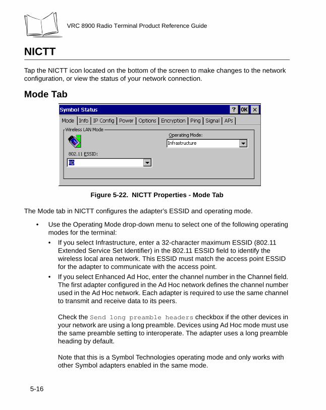
Mode Tab
Figure 5-22. NICTT Properties - Mode Tab
The Mode tab in NICTT configures the adapter’s ESSID and operating mode.
• Use the Operating Mode drop-down menu to select one of the following operating modes for the terminal:
• If you select Infrastructure, enter a 32-character maximum ESSID (802.11 Extended Service Set Identifier) in the 802.11 ESSID field to identify the wireless local area network. This ESSID must match the access point ESSID for the adapter to communicate with the access point.
• If you select Enhanced Ad Hoc, enter the channel number in the Channel field. The first adapter configured in the Ad Hoc network defines the channel number used in the Ad Hoc network. Each adapter is required to use the same channel to transmit and receive data to its peers.
Check the Send long preamble headers checkbox if the other devices in your network are using a long preamble. Devices using Ad Hoc mode must use the same preamble setting to interoperate. The adapter uses a long preamble heading by default.
Note that this is a Symbol Technologies operating mode and only works with other Symbol adapters enabled in the same mode.
5-16
Spectrum24 Network Configuration
• If you select Ad Hoc, enter a 32-character maximum ESSID (802.11 Extended Service Set Identifier) in the 802.11 ESSID field to identify the wireless local area network. This ESSID must match the ESSID of other devices using the Ad Hoc mode.
Enter the channel number in the Channel field. The first adapter configured in the Ad Hoc network defines the channel number used in the Ad Hoc network. Each adapter is required to use the same channel to transmit and receive data to its peers.
Check the Send long preamble headers checkbox if the other devices in your network are using a long preamble. Devices using Ad Hoc mode must use the same preamble setting to interoperate. The adapter uses a long preamble heading by default.
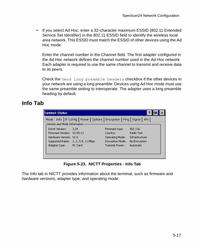
Info Tab
Figure 5-23. NICTT Properties - Info Tab
The Info tab in NICTT provides information about the terminal, such as firmware and hardware versions, adapter type, and operating mode.
5-17
VRC 8900 Radio Terminal Product Reference Guide
IP Config Tab
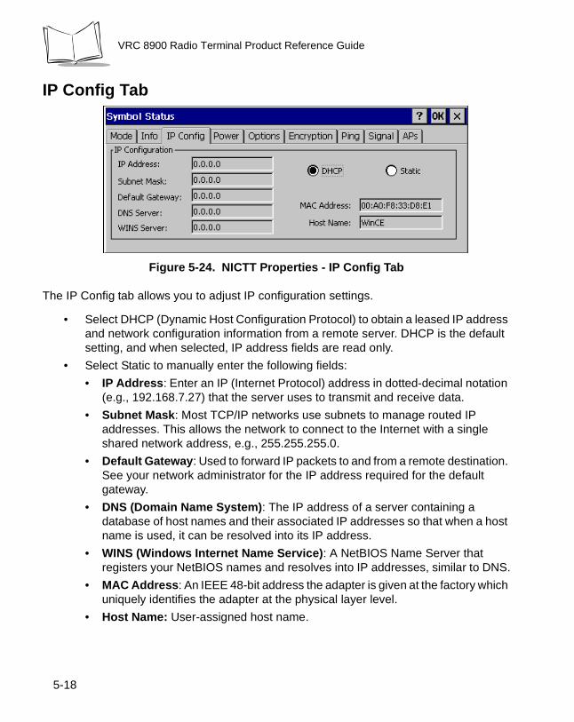
Figure 5-24. NICTT Properties - IP Config Tab
The IP Config tab allows you to adjust IP configuration settings.
• Select DHCP (Dynamic Host Configuration Protocol) to obtain a leased IP address and network configuration information from a remote server. DHCP is the default setting, and when selected, IP address fields are read only.
• Select Static to manually enter the following fields:
• IP Address: Enter an IP (Internet Protocol) address in dotted-decimal notation (e.g., 192.168.7.27) that the server uses to transmit and receive data.
• Subnet Mask: Most TCP/IP networks use subnets to manage routed IP addresses. This allows the network to connect to the Internet with a single shared network address, e.g., 255.255.255.0.
• Default Gateway: Used to forward IP packets to and from a remote destination. See your network administrator for the IP address required for the default gateway.
• DNS (Domain Name System): The IP address of a server containing a database of host names and their associated IP addresses so that when a host name is used, it can be resolved into its IP address.
• WINS (Windows Internet Name Service): A NetBIOS Name Server that registers your NetBIOS names and resolves into IP addresses, similar to DNS.
• MAC Address: An IEEE 48-bit address the adapter is given at the factory which uniquely identifies the adapter at the physical layer level.
• Host Name: User-assigned host name.
5-18
Spectrum24 Network Configuration
Power Tab
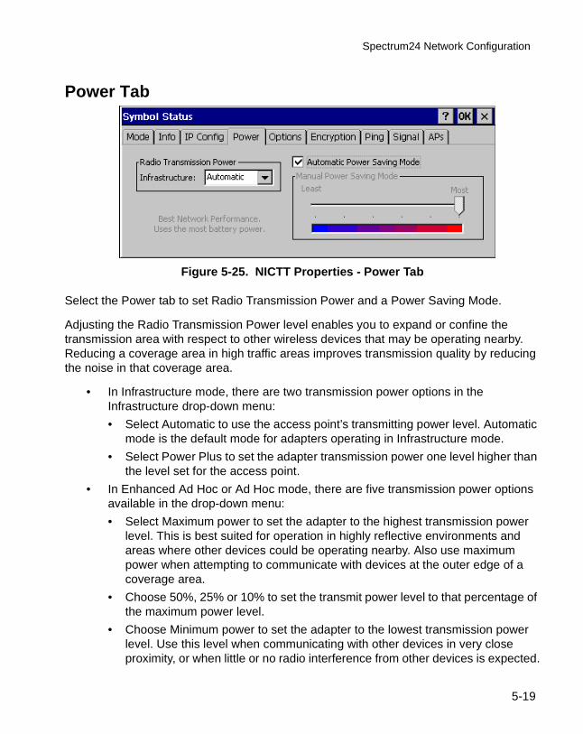
Figure 5-25. NICTT Properties - Power Tab
Select the Power tab to set Radio Transmission Power and a Power Saving Mode.
Adjusting the Radio Transmission Power level enables you to expand or confine the transmission area with respect to other wireless devices that may be operating nearby. Reducing a coverage area in high traffic areas improves transmission quality by reducing the noise in that coverage area.
• In Infrastructure mode, there are two transmission power options in the Infrastructure drop-down menu:
• Select Automatic to use the access point’s transmitting power level. Automatic mode is the default mode for adapters operating in Infrastructure mode.
• Select Power Plus to set the adapter transmission power one level higher than the level set for the access point.
• In Enhanced Ad Hoc or Ad Hoc mode, there are five transmission power options available in the drop-down menu:
• Select Maximum power to set the adapter to the highest transmission power level. This is best suited for operation in highly reflective environments and areas where other devices could be operating nearby. Also use maximum power when attempting to communicate with devices at the outer edge of a coverage area.
• Choose 50%, 25% or 10% to set the transmit power level to that percentage of the maximum power level.
• Choose Minimum power to set the adapter to the lowest transmission power level. Use this level when communicating with other devices in very close proximity, or when little or no radio interference from other devices is expected.
5-19
VRC 8900 Radio Terminal Product Reference Guide
• Check Automatic Power Saving Mode to switch to the Best Network Performance when the AC power supply is used.
When using the battery, select an appropriate setting between Best Network Performance and Acceptable Network Performance based on real-time analysis of the network usage. Automatic Power Saving Mode is the default setting and extends the operating time before the battery must be recharged.
• Uncheck Automatic Power Saving Mode to select Manual Power Saving Mode, which allows you to set the slider to a performance level suited to the intended operation. There are 6 settings ranging from the best network performance, which uses the most battery power, to acceptable network performance, which uses the least battery power.
Note: Power savings modes are not available in Enhanced Ad Hoc operating mode.
5-20
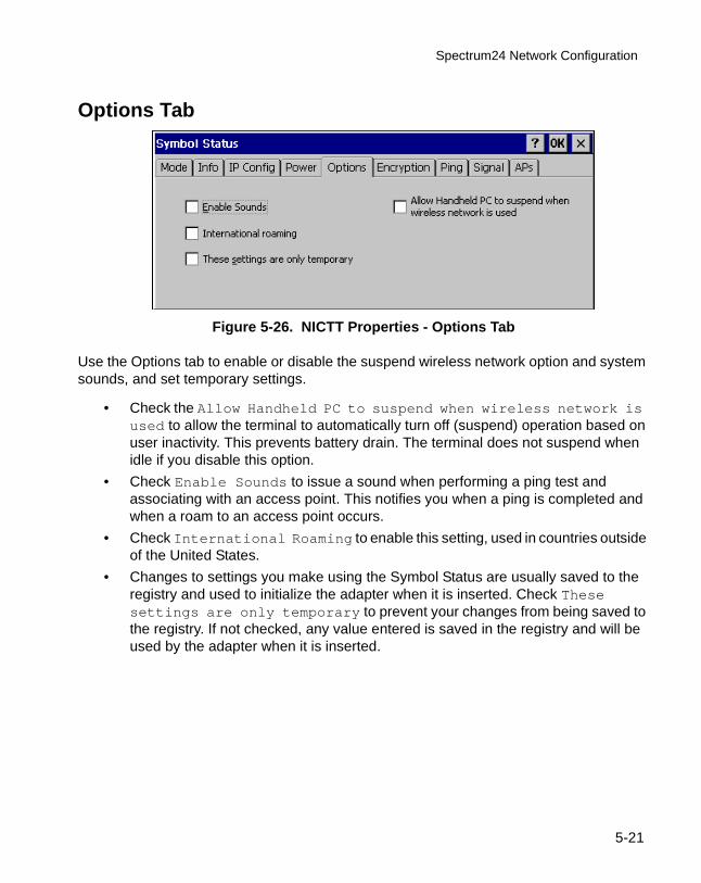
Spectrum24 Network Configuration
Options Tab
Figure 5-26. NICTT Properties - Options Tab
Use the Options tab to enable or disable the suspend wireless network option and system sounds, and set temporary settings.
• Check the Allow Handheld PC to suspend when wireless network is used to allow the terminal to automatically turn off (suspend) operation based on user inactivity. This prevents battery drain. The terminal does not suspend when idle if you disable this option.
• Check Enable Sounds to issue a sound when performing a ping test and associating with an access point. This notifies you when a ping is completed and when a roam to an access point occurs.
• Check International Roaming to enable this setting, used in countries outside of the United States.
• Changes to settings you make using the Symbol Status are usually saved to the registry and used to initialize the adapter when it is inserted. Check These settings are only temporary to prevent your changes from being saved to the registry. If not checked, any value entered is saved in the registry and will be used by the adapter when it is inserted.
5-21
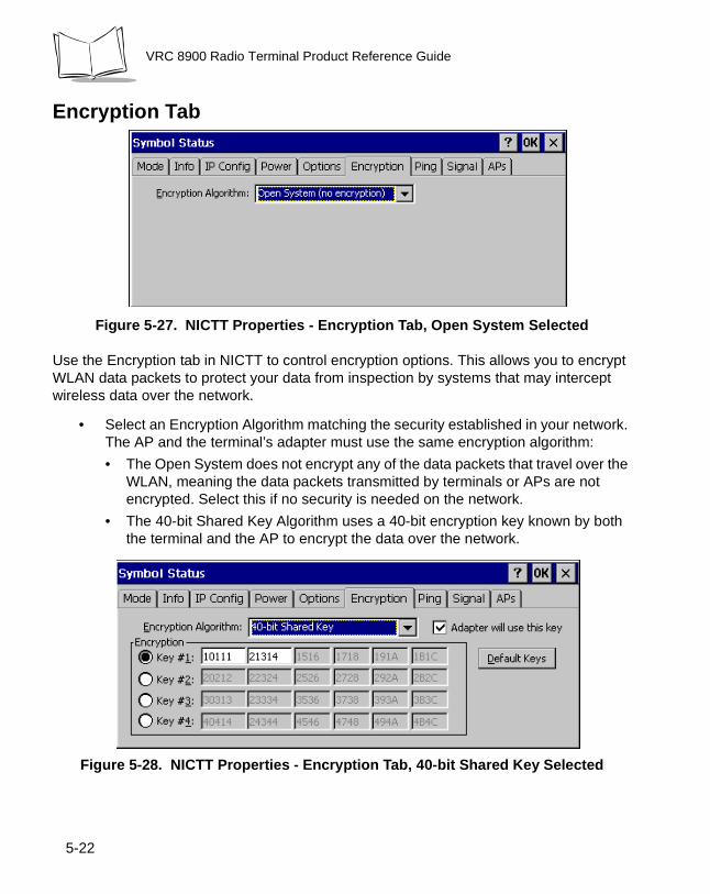
VRC 8900 Radio Terminal Product Reference Guide
Encryption Tab
Figure 5-27. NICTT Properties - Encryption Tab, Open System Selected
Use the Encryption tab in NICTT to control encryption options. This allows you to encrypt WLAN data packets to protect your data from inspection by systems that may intercept wireless data over the network.
• Select an Encryption Algorithm matching the security established in your network. The AP and the terminal’s adapter must use the same encryption algorithm:
• The Open System does not encrypt any of the data packets that travel over the WLAN, meaning the data packets transmitted by terminals or APs are not encrypted. Select this if no security is needed on the network.
• The 40-bit Shared Key Algorithm uses a 40-bit encryption key known by both the terminal and the AP to encrypt the data over the network.
Figure 5-28. NICTT Properties - Encryption Tab, 40-bit Shared Key Selected
5-22
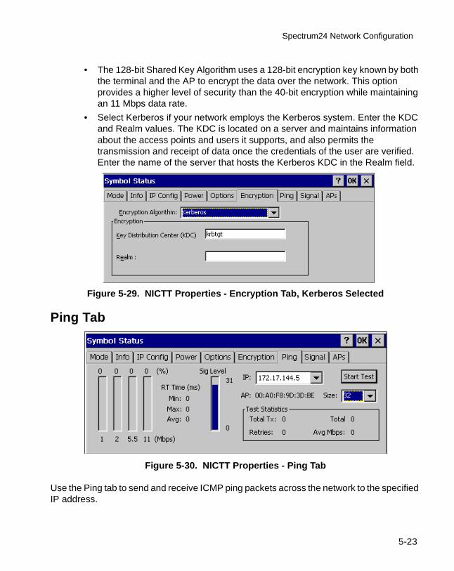
Spectrum24 Network Configuration
• The 128-bit Shared Key Algorithm uses a 128-bit encryption key known by both the terminal and the AP to encrypt the data over the network. This option provides a higher level of security than the 40-bit encryption while maintaining an 11 Mbps data rate.
• Select Kerberos if your network employs the Kerberos system. Enter the KDC and Realm values. The KDC is located on a server and maintains information about the access points and users it supports, and also permits the transmission and receipt of data once the credentials of the user are verified. Enter the name of the server that hosts the Kerberos KDC in the Realm field.
Figure 5-29. NICTT Properties - Encryption Tab, Kerberos Selected
Ping Tab
Figure 5-30. NICTT Properties - Ping Tab
Use the Ping tab to send and receive ICMP ping packets across the network to the specified IP address.
5-23
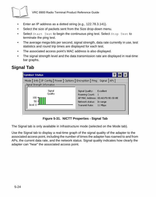
VRC 8900 Radio Terminal Product Reference Guide
• Enter an IP address as a dotted string (e.g., 122.78.3.141).
• Select the size of packets sent from the Size drop-down menu.
• Select Start Test to begin the continuous ping test. Select Stop Test to terminate the ping test.
• The average mega-bits per second, signal strength, data rate currently in use, test statistics and round trip times are displayed for each test.
• The associated access point’s MAC address is also displayed.
• The signal strength level and the data transmission rate are displayed in real-time bar graphs.
Signal Tab
Figure 5-31. NICTT Properties - Signal Tab
The Signal tab is only available in Infrastructure mode (selected on the Mode tab).
Use the Signal tab to display a real-time graph of the signal quality of the adapter to the associated access point, including the number of times the adapter has roamed to and from APs, the current data rate, and the network status. Signal quality indicates how clearly the adapter can “hear” the associated access point.
5-24
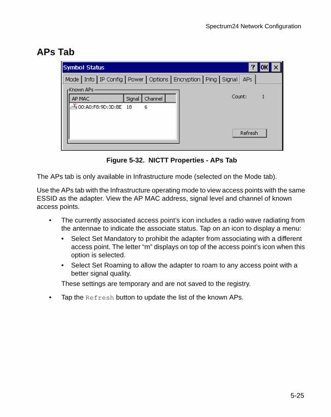
Spectrum24 Network Configuration
APs Tab
Figure 5-32. NICTT Properties - APs Tab
The APs tab is only available in Infrastructure mode (selected on the Mode tab).
Use the APs tab with the Infrastructure operating mode to view access points with the same ESSID as the adapter. View the AP MAC address, signal level and channel of known access points.
• The currently associated access point’s icon includes a radio wave radiating from the antennae to indicate the associate status. Tap on an icon to display a menu:
• Select Set Mandatory to prohibit the adapter from associating with a different access point. The letter “m” displays on top of the access point’s icon when this option is selected.
• Select Set Roaming to allow the adapter to roam to any access point with a better signal quality.
These settings are temporary and are not saved to the registry.
• Tap the Refresh button to update the list of the known APs.
5-25

VRC 8900 Radio Terminal Product Reference Guide
5-26
Chapter 6 Configuring the Terminal
Introduction
This chapter describes the terminal’s Flash partitions and how they are used to specify and load files into the Flash memory of the terminal using ActiveSync.
Flash Partitions
In addition to the RAM-based storage standard on Windows CE terminals, the VRC 8900 is equipped with a non-volatile Flash-based storage area which can store data (partitions) that cannot be corrupted by a cold boot. This Flash area is divided into two categories: Flash File System (FFS) Partitions and Non-FFS Partitions.
FFS PartitionsThe terminal includes one FFS partition. This partition appears to the terminal as a hard drive that the OS file system can write files to and read files from. Data is retained even if power is removed.
The FFS Partition is used to store application programs needed to operate the terminal. This partition is also available for user data files generated by your custom programs.
6-1
VRC 8900 Radio Terminal Product Reference Guide
The partition contains one volume with the folder CopyToRAM, which contains four subfolders:
Non-FFS PartitionsNon-FFS Partitions include software and data pre-loaded on your terminal. Unlike the FFS Partition, these partitions are not visible when the operating system is running. They also contain system information. Non-FFS Partitions include the following:
• Windows CE: the complete Windows CE operating system is stored on Flash devices. If necessary, the entire OS image may be downloaded to the terminal using files provided by Symbol. Any upgrades must be obtained from Symbol. This partition is mandatory for the VRC 8900.
• Boot Loader: initializes the CE operating system prior to starting CE and provides a simple method of updating the Flash contents via a serial port.
Downloading the Operating System
To download the operating system via the serial port, the following equipment is required:
• PC
• ActiveSync cable
• Compressed Windows CE image (*.BIN file)
• OSUPDATE.EXE
1. Connect the ActiveSync cable to the COM1 port on the terminal and an available COM port on the PC.
CopyToRAM User application files which need to be loaded into RAM prior to execution
\Root applications or files placed in this folder are copied to the root directory while maintaining their directory structure
\Startup applications placed in this folder are permanently stored in Flash but copied to DRAM and executed on start up
\System applications or data placed in this folder are permanently stored in Flash but copied to the \Windows folder in DRAM upon cold/warm boot
\User User application files
6-2
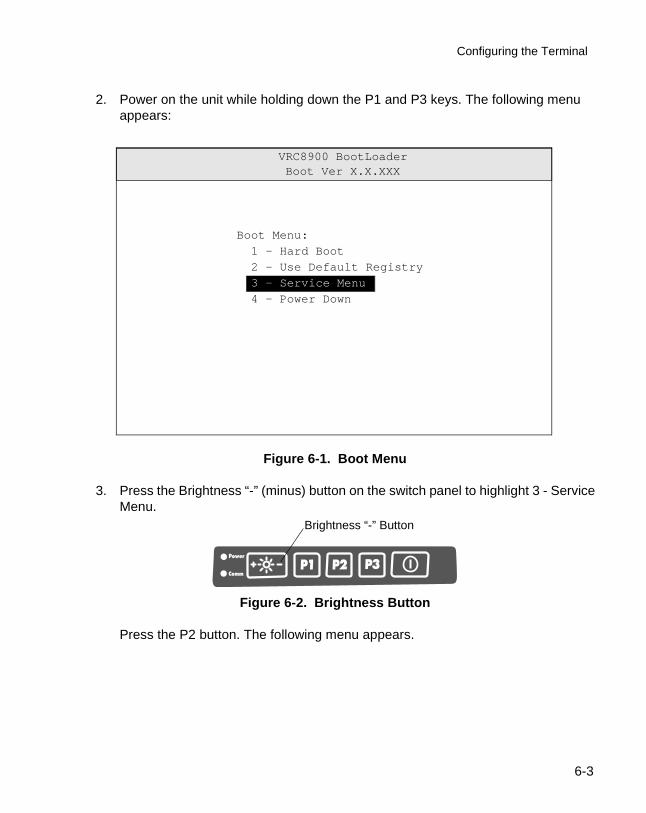
Configuring the Terminal
2. Power on the unit while holding down the P1 and P3 keys. The following menu appears:
Figure 6-1. Boot Menu
3. Press the Brightness “-” (minus) button on the switch panel to highlight 3 - Service Menu.
Figure 6-2. Brightness Button
Press the P2 button. The following menu appears.
VRC8900 BootLoaderBoot Ver X.X.XXX
Boot Menu:
1 - Hard Boot
2 - Use Default Registry
3 - Service Menu
4 - Power Down
Brightness “-” Button
6-3
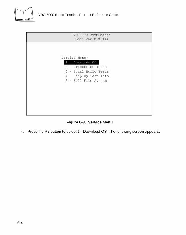
VRC 8900 Radio Terminal Product Reference Guide
Figure 6-3. Service Menu
4. Press the P2 button to select 1 - Download OS. The following screen appears.
VRC8900 BootLoaderBoot Ver X.X.XXX
Service Menu:
1 - Download OS
2 - Production Tests
3 - Final Build Tests
4 - Display Test Info
5 - Kill File System
6-4
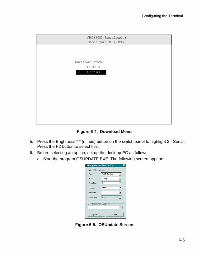
Configuring the Terminal
Figure 6-4. Download Menu
5. Press the Brightness “-” (minus) button on the switch panel to highlight 2 - Serial. Press the P2 button to select this.
6. Before selecting an option, set up the desktop PC as follows:
a. Start the program OSUPDATE.EXE. The following screen appears:
Figure 6-5. OSUpdate Screen
VRC8900 BootLoaderBoot Ver X.X.XXX
Download from:
1 - PCMCIA
2 - Serial
6-5
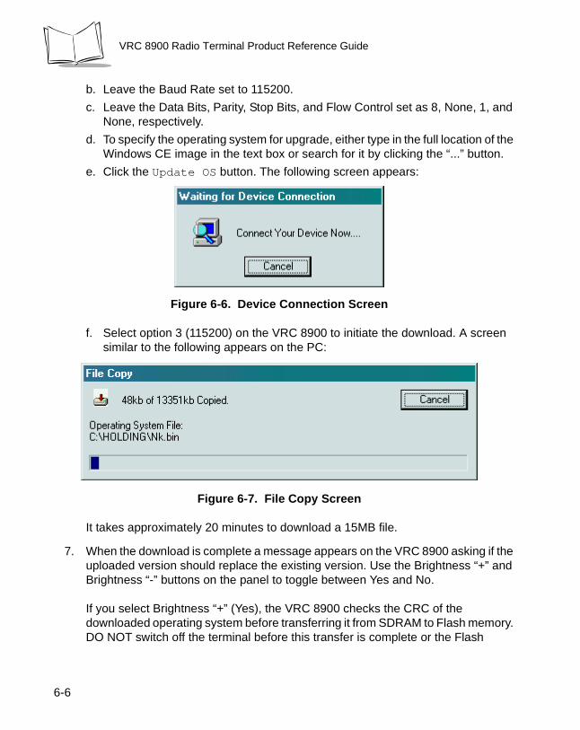
VRC 8900 Radio Terminal Product Reference Guide
b. Leave the Baud Rate set to 115200.
c. Leave the Data Bits, Parity, Stop Bits, and Flow Control set as 8, None, 1, and None, respectively.
d. To specify the operating system for upgrade, either type in the full location of the Windows CE image in the text box or search for it by clicking the “...” button.
e. Click the Update OS button. The following screen appears:
Figure 6-6. Device Connection Screen
f. Select option 3 (115200) on the VRC 8900 to initiate the download. A screen similar to the following appears on the PC:
Figure 6-7. File Copy Screen
It takes approximately 20 minutes to download a 15MB file.
7. When the download is complete a message appears on the VRC 8900 asking if the uploaded version should replace the existing version. Use the Brightness “+” and Brightness “-” buttons on the panel to toggle between Yes and No.
If you select Brightness “+” (Yes), the VRC 8900 checks the CRC of the downloaded operating system before transferring it from SDRAM to Flash memory. DO NOT switch off the terminal before this transfer is complete or the Flash
6-6
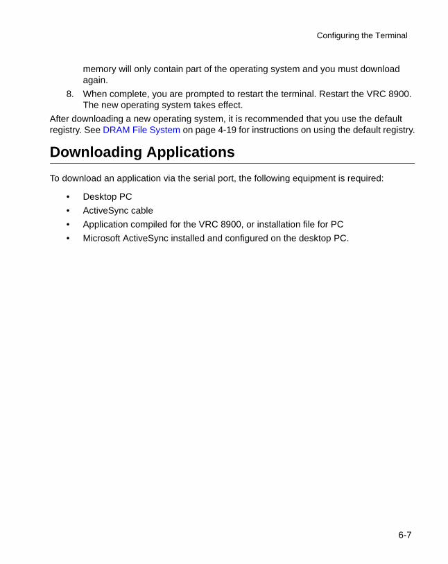
Configuring the Terminal
memory will only contain part of the operating system and you must download again.
8. When complete, you are prompted to restart the terminal. Restart the VRC 8900. The new operating system takes effect.
After downloading a new operating system, it is recommended that you use the default registry. See DRAM File System on page 4-19 for instructions on using the default registry.
Downloading Applications
To download an application via the serial port, the following equipment is required:
• Desktop PC
• ActiveSync cable
• Application compiled for the VRC 8900, or installation file for PC
• Microsoft ActiveSync installed and configured on the desktop PC.
6-7
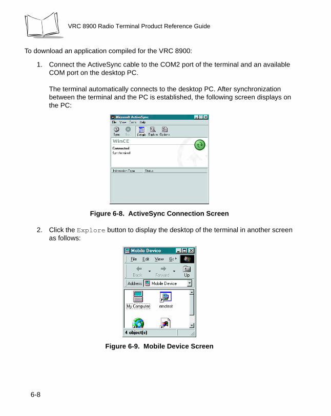
VRC 8900 Radio Terminal Product Reference Guide
To download an application compiled for the VRC 8900:
1. Connect the ActiveSync cable to the COM2 port of the terminal and an available COM port on the desktop PC.
The terminal automatically connects to the desktop PC. After synchronization between the terminal and the PC is established, the following screen displays on the PC:
Figure 6-8. ActiveSync Connection Screen
2. Click the Explore button to display the desktop of the terminal in another screen as follows:
Figure 6-9. Mobile Device Screen
6-8
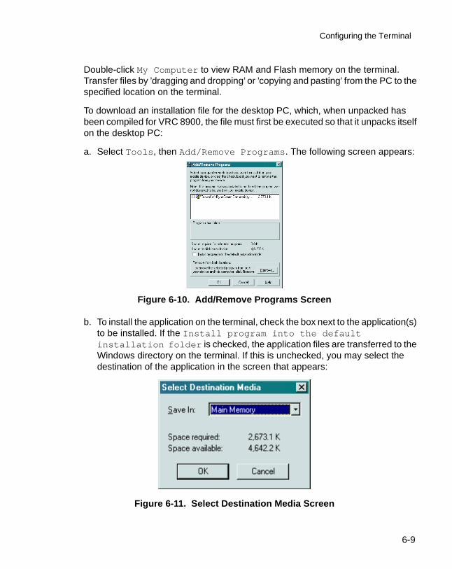
Configuring the Terminal
Double-click My Computer to view RAM and Flash memory on the terminal. Transfer files by ’dragging and dropping’ or ’copying and pasting’ from the PC to the specified location on the terminal.
To download an installation file for the desktop PC, which, when unpacked has been compiled for VRC 8900, the file must first be executed so that it unpacks itself on the desktop PC:
a. Select Tools, then Add/Remove Programs. The following screen appears:
Figure 6-10. Add/Remove Programs Screen
b. To install the application on the terminal, check the box next to the application(s) to be installed. If the Install program into the default installation folder is checked, the application files are transferred to the Windows directory on the terminal. If this is unchecked, you may select the destination of the application in the screen that appears:
Figure 6-11. Select Destination Media Screen
6-9
VRC 8900 Radio Terminal Product Reference Guide
Refer to DRAM File System on page 4-19 to increase memory if the program memory availability is lower than required.
3. Continue with the on-screen prompts on the PC and the terminal to complete the application installation.
Note: If the application, or part of it, is installed in DRAM, it will be lost if the back-up battery is allowed to discharge or a cold boot is performed.
6-10

Chapter 7 ActiveSync
Introduction
This chapter describes communication between the terminal and a desktop PC using ActiveSync. The minimum desktop PC requirements for ActiveSync are:
• Windows 2000, Windows NT4 with Service Pack 3 or later, Windows Me, or Windows 95/98
• Desktop computer with a Pentium processor for Windows NT (166 MHz required for Windows 2000), Windows Me (150 MHz required for Windows Me), or a 486/66 DX or higher processor (Pentium P90 recommended) for Windows 95/98
• 16MB of memory for Windows 95/98 (more memory will improve performance) or Windows NT Workstation 4.0 (32MB recommended for Windows NT, 64MB recommended for Windows 2000), 32MB of memory for Windows Me
• Hard disk drive with 10 to 50MB of available space (actual requirements vary based on selection of features and user's current system configuration)
• Available 9 or 25-pin communications port (adapter required for 25-pin communications port), or USB port (available for Windows 95/98 or Windows 2000 only)
• CD-ROM drive
• VGA graphics card or compatible video graphics adapter with 256 color or higher
• Keyboard
• Mouse or compatible pointing device.
7-1
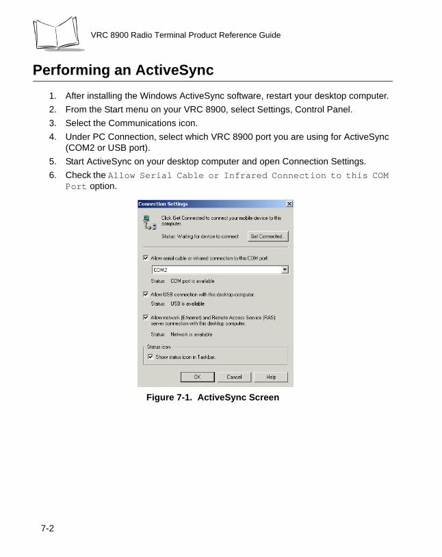
VRC 8900 Radio Terminal Product Reference Guide
Performing an ActiveSync
1. After installing the Windows ActiveSync software, restart your desktop computer.
2. From the Start menu on your VRC 8900, select Settings, Control Panel.
3. Select the Communications icon.
4. Under PC Connection, select which VRC 8900 port you are using for ActiveSync (COM2 or USB port).
5. Start ActiveSync on your desktop computer and open Connection Settings.
6. Check the Allow Serial Cable or Infrared Connection to this COM Port option.
Figure 7-1. ActiveSync Screen
7-2
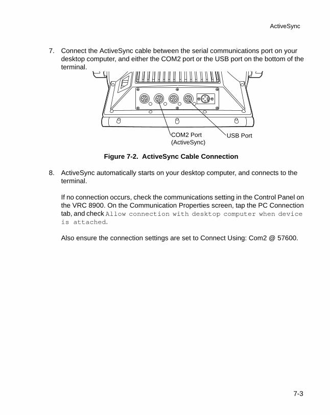
ActiveSync
7. Connect the ActiveSync cable between the serial communications port on your desktop computer, and either the COM2 port or the USB port on the bottom of the terminal.
Figure 7-2. ActiveSync Cable Connection
8. ActiveSync automatically starts on your desktop computer, and connects to the terminal.
If no connection occurs, check the communications setting in the Control Panel on the VRC 8900. On the Communication Properties screen, tap the PC Connection tab, and check Allow connection with desktop computer when device is attached.
Also ensure the connection settings are set to Connect Using: Com2 @ 57600.
COM2 Port(ActiveSync)
USB Port
7-3

VRC 8900 Radio Terminal Product Reference Guide
7-4
Chapter 8 Maintenance and Troubleshooting
Maintaining the Terminal
The terminal is factory-sealed and contains no user-serviceable parts. Only qualified Symbol Service Centers should service the terminal. Refer to Symbol Support Center on page ix.
Protective caps are attached to the ports on the back of the terminal. Place them over unused ports for protection.
Cleaning the Terminal
The terminal requires a minimal amount of maintenance. To prolong its life and avoid problems, keep the terminal clean. Use a clean, soft cloth dampened with a mild cleanser such as soap and water to clean the terminal. Do NOT use cleaners containing a high percentage of alcohol, such as Isopropyl Alcohol. Do NOT use abrasive paper/cloth or abrasive/corrosive cleaners.
Storage
Store the terminal in a cool, dry place away from dust. The terminal’s internal battery completely discharges in 72 hours. All non-volatile data is lost when the internal battery is fully discharged.
8-1

VRC 8900 Radio Terminal Product Reference Guide
Troubleshooting
Table 8-1 covers some common terminal problems and corrective actions to take.
Table 8-1. Terminal Problems
Symptom Possible Cause Action
Terminal does not power on or shuts off suddenly.
Power switch on back of terminal is in the Off position.
Turn the power switch on.
Power cable not connected or unplugged.
Connect power cable to power cable portion underside of terminal. Turn the power switch on, then press the Suspend Button to boot up the terminal.
If the terminal is powered by a vehicle battery, the vehicle battery is depleted.
Replace or charge the vehicle battery.
Cannot see characters on display.
Terminal not powered on (Power LED is off).
Turn the power switch on.Press the Suspend Button.
Screen is too bright/dark. Adjust the brightness; see Adjusting the Brightness on page 4-16.
Display not adjusted properly. Select Display in the Control Panel settings and adjust the display.
The terminal is in Suspend mode (indicated by a yellow Power LED).
Press the Suspend Button to turn on the terminal.
Touchscreen not working. Display not properly calibrated.
Recalibrate the screen through the Control Panel Calibration utility. If problem continues, contact Symbol Support Center. See Symbol Support Center on page ix.
Optional scanner does not operate.
Scanner is not properly connected to the terminal.
Connect the scanner to the COM1 port and power up the terminal. If the problem continues, refer to the scanner Quick Reference Guide.
8-2
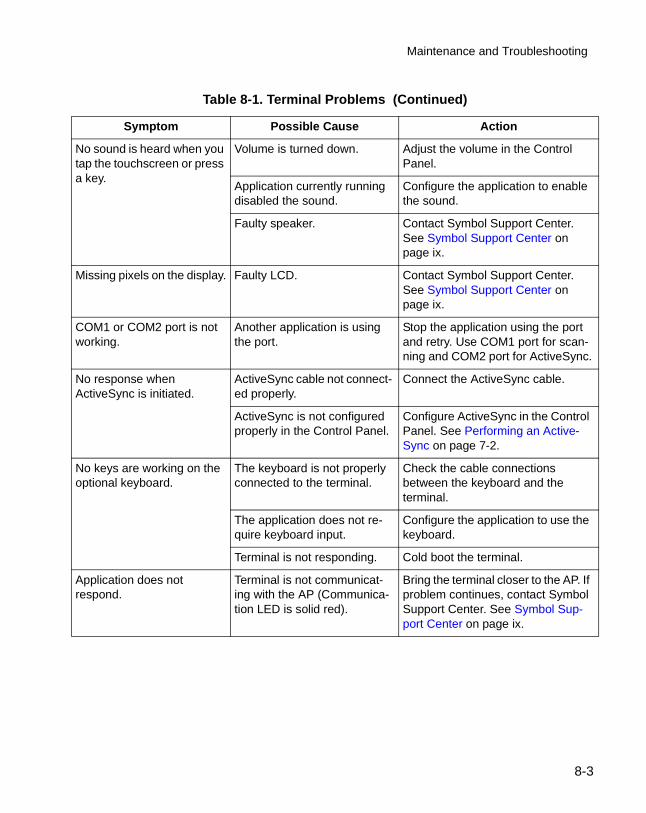
Maintenance and Troubleshooting
No sound is heard when you tap the touchscreen or press a key.
Volume is turned down. Adjust the volume in the Control Panel.
Application currently running disabled the sound.
Configure the application to enable the sound.
Faulty speaker. Contact Symbol Support Center. See Symbol Support Center on page ix.
Missing pixels on the display. Faulty LCD. Contact Symbol Support Center. See Symbol Support Center on page ix.
COM1 or COM2 port is not working.
Another application is using the port.
Stop the application using the port and retry. Use COM1 port for scan-ning and COM2 port for ActiveSync.
No response when ActiveSync is initiated.
ActiveSync cable not connect-ed properly.
Connect the ActiveSync cable.
ActiveSync is not configured properly in the Control Panel.
Configure ActiveSync in the Control Panel. See Performing an Active-Sync on page 7-2.
No keys are working on the optional keyboard.
The keyboard is not properly connected to the terminal.
Check the cable connections between the keyboard and the terminal.
The application does not re-quire keyboard input.
Configure the application to use the keyboard.
Terminal is not responding. Cold boot the terminal.
Application does not respond.
Terminal is not communicat-ing with the AP (Communica-tion LED is solid red).
Bring the terminal closer to the AP. If problem continues, contact Symbol Support Center. See Symbol Sup-port Center on page ix.
Table 8-1. Terminal Problems (Continued)
Symptom Possible Cause Action
8-3

VRC 8900 Radio Terminal Product Reference Guide
8-4
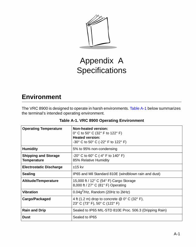
Appendix ASpecifications
Environment
The VRC 8900 is designed to operate in harsh environments. Table A-1 below summarizes the terminal’s intended operating environment.
Table A-1. VRC 8900 Operating Environment
Operating Temperature Non-heated version:0° C to 50° C (32° F to 122° F) Heated version:-30° C to 50° C (-22° F to 122° F)
Humidity 5% to 95% non-condensing
Shipping and Storage Temperature
-20° C to 60° C (-4° F to 140° F)85% Relative Humidity
Electrostatic Discharge ±15 kv
Sealing IP65 and Mil Standard 810E (windblown rain and dust)
Altitude/Temperature 15,000 ft / 12° C (54° F) Cargo Storage8,000 ft / 27° C (81° F) Operating
Vibration 0.04g2/Hz, Random (20Hz to 2kHz)
Cargo/Packaged 4 ft (1.2 m) drop to concrete @ 0° C (32° F), 23° C (73° F), 50° C (122° F)
Rain and Drip Sealed to IP65 MIL-STD 810E Proc. 506.3 (Dripping Rain)
Dust Sealed to IP65
A-1
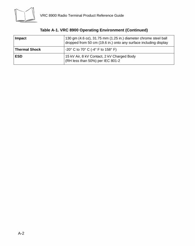
VRC 8900 Radio Terminal Product Reference Guide
Impact 130 gm (4.6 oz), 31.75 mm (1.25 in.) diameter chrome steel ball dropped from 50 cm (19.6 in.) onto any surface including display
Thermal Shock -20° C to 70° C (-4° F to 158° F)
ESD 15 kV Air, 8 kV Contact, 2 kV Charged Body(RH less than 50%) per IEC 801-2
Table A-1. VRC 8900 Operating Environment (Continued)
A-2
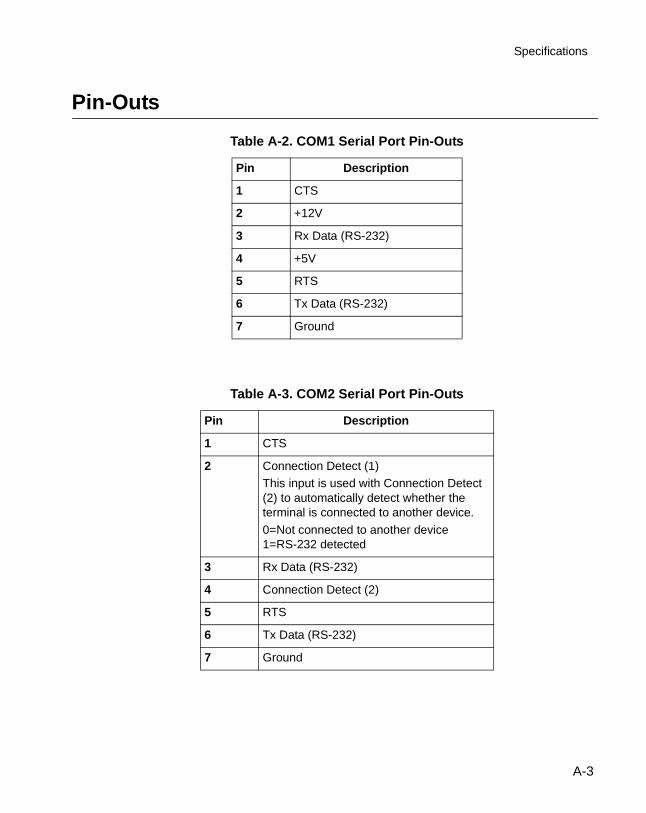
Specifications
Pin-Outs
Table A-2. COM1 Serial Port Pin-Outs
Pin Description
1 CTS
2 +12V
3 Rx Data (RS-232)
4 +5V
5 RTS
6 Tx Data (RS-232)
7 Ground
Table A-3. COM2 Serial Port Pin-Outs
Pin Description
1 CTS
2 Connection Detect (1)This input is used with Connection Detect (2) to automatically detect whether the terminal is connected to another device.
0=Not connected to another device1=RS-232 detected
3 Rx Data (RS-232)
4 Connection Detect (2)
5 RTS
6 Tx Data (RS-232)
7 Ground
A-3
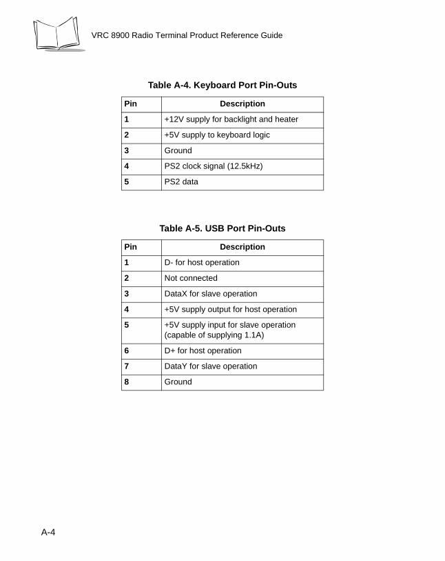
VRC 8900 Radio Terminal Product Reference Guide
Table A-4. Keyboard Port Pin-Outs
Pin Description
1 +12V supply for backlight and heater
2 +5V supply to keyboard logic
3 Ground
4 PS2 clock signal (12.5kHz)
5 PS2 data
Table A-5. USB Port Pin-Outs
Pin Description
1 D- for host operation
2 Not connected
3 DataX for slave operation
4 +5V supply output for host operation
5 +5V supply input for slave operation (capable of supplying 1.1A)
6 D+ for host operation
7 DataY for slave operation
8 Ground
A-4
Index
Numerics11 Mbps
advanced properties . . . . . . . . . . . . . 5-16APs . . . . . . . . . . . . . . . . . . . . . . . . . . 5-25configuring . . . . . . . . . . . . . . . . . . . . . . 5-8encryption . . . . . . . . . . . . . . . . 5-13, 5-22info . . . . . . . . . . . . . . . . . . . . . . . . . . . 5-17IP address . . . . . . . . . . . . . . . . . . . . . . 5-8IP config . . . . . . . . . . . . . . . . . . . . . . . 5-18mobile unit . . . . . . . . . . . . . . . . . . . . . 5-10mode . . . . . . . . . . . . . . . . . . . . . . . . . 5-16name servers . . . . . . . . . . . . . . . . . . . . 5-9options . . . . . . . . . . . . . . . . . . . . . . . . 5-21ping . . . . . . . . . . . . . . . . . . . . . . . . . . 5-23power . . . . . . . . . . . . . . . . . . . . 5-11, 5-19setting password . . . . . . . . . . . . . . . . 5-15signal . . . . . . . . . . . . . . . . . . . . . . . . . 5-24transmission power . . . . . . . . . . . . . . 5-12WLAN adapter . . . . . . . . . . . . . . . . . . 5-15
2 Mbpsconfiguring . . . . . . . . . . . . . . . . . . . . . . 5-1encryption . . . . . . . . . . . . . . . . . . . . . . 5-5IP address . . . . . . . . . . . . . . . . . . . . . . 5-2micro AP . . . . . . . . . . . . . . . . . . . . . . . 5-4mobile unit . . . . . . . . . . . . . . . . . . . . . . 5-4name servers . . . . . . . . . . . . . . . . . . . . 5-3setting password . . . . . . . . . . . . . . . . . 5-7WLAN adapter . . . . . . . . . . . . . . . . . . . 5-6
AAC power connection . . . . . . . . . . . . . . . . . 2-9accessories
connecting . . . . . . . . . . . . . . . . . . . . . 4-17
accessories and peripherals . . . . . . . . . . . 1-3ActiveSync . . . . . . . . . . . . . . . . . . . . . . . . . 7-1
performing . . . . . . . . . . . . . . . . . . . . . . 7-2ActiveSync connection . . . . . . . . . . . . . . . 4-17allocating memory . . . . . . . . . . . . . . . . . . 4-19
Bbattery . . . . . . . . . . . . . . . . . . . . . . . . . . . 2-12booting
cold . . . . . . . . . . . . . . . . . . . . . . . . . . . 4-3warm . . . . . . . . . . . . . . . . . . . . . . . . . . 4-2
booting the terminal . . . . . . . . . . . . . . . . . . 4-2buttons
P . . . . . . . . . . . . . . . . . . . . . . . . . . . . . 4-4suspend . . . . . . . . . . . . . . . . . . . . . . . 4-1
Ccables
performing ActiveSync . . . . . . . . . . . . 7-2routing . . . . . . . . . . . . . . . . . . . . . . . . . 2-2
calibration . . . . . . . . . . . . . . . . . . . . . . . . . . 4-9CE SDK . . . . . . . . . . . . . . . . . . . . . . . . . . . 3-2chapter descriptions . . . . . . . . . . . . . . . . . . . viicleaning the terminal . . . . . . . . . . . . . . . . . 8-1cold boot . . . . . . . . . . . . . . . . . . . . . . . 4-2, 4-3communications . . . . . . . . . . . . . . . . . . . . . 7-1connecting a scanner . . . . . . . . . . . . . . . . 4-17connecting accessories . . . . . . . . . . . . . . 4-17contrast . . . . . . . . . . . . . . . . . . . . . . . . . . 4-16
Ddesktop
Index-1
VRC 8900 Radio Terminal Product Reference Guide
locking . . . . . . . . . . . . . . . . . . . . . . . . . 4-9displaying bar code information . . . . . . . . 4-17downloading
applications . . . . . . . . . . . . . . . . . . . . . 6-7operating system . . . . . . . . . . . . . . . . 6-2
DRAM file system . . . . . . . . . . . . . . . . . . . 4-19
Eenvironment . . . . . . . . . . . . . . . . . . . . . . . . A-1
FFFS Partitions . . . . . . . . . . . . . . . . . . . . . . 6-1files
DRAM file system . . . . . . . . . . . . . . . 4-19flash file system . . . . . . . . . . . . . . . . 4-19saving . . . . . . . . . . . . . . . . . . . . . . . . 4-19
filter boxconnections . . . . . . . . . . . . . . . . . . . . . 2-8
Flash File System . . . . . . . . . . . . . . . . . . . 4-19Flash Partitions . . . . . . . . . . . . . . . . . . . . . 6-1flash partitions
FFS . . . . . . . . . . . . . . . . . . . . . . . . . . . 6-1non-FFS . . . . . . . . . . . . . . . . . . . . . . . 6-2
front view . . . . . . . . . . . . . . . . . . . . . . . . . . 1-2
Hhost PC
minimum system requirements . . . . . . 3-1
Iinstallation kit of parts . . . . . . . . . . . . . . . . . 2-4installing SDK . . . . . . . . . . . . . . . . . . . . . . . 3-1installing the terminal . . . . . . . . . . . . . . . . . 2-5installing your terminal . . . . . . . . . . . . . . . . 2-2internal battery . . . . . . . . . . . . . . . . . . . . . 2-12
Kkeyboard . . . . . . . . . . . . . . . . . . . . . . . . . . 4-5
descriptions . . . . . . . . . . . . . . . . . . . . . 4-6mappings . . . . . . . . . . . . . . . . . . . . . . 4-7
kit
installation parts . . . . . . . . . . . . . . . . . . 2-4
Llocking the desktop . . . . . . . . . . . . . . . . . . . 4-9
Mmaintaining the terminal . . . . . . . . . . . . . . . 8-1memory
allocation . . . . . . . . . . . . . . . . . . . . . . 4-19modes
release to cold boot . . . . . . . . . . . . . . . 4-2release to suspend . . . . . . . . . . . . . . . . 4-2release to warm boot . . . . . . . . . . . . . . 4-2
NNon-FFS Partitions . . . . . . . . . . . . . . . . . . . 6-2notational conventions . . . . . . . . . . . . . . . . viii
Ooperating environment . . . . . . . . . . . . . . . .A-1operating system
downloading . . . . . . . . . . . . . . . . . . . . . 6-2optional accessories . . . . . . . . . . . . . . . . . . 1-3
PP keys . . . . . . . . . . . . . . . . . . . . . . . . . . . . . 4-4partitions
non-FFS . . . . . . . . . . . . . . . . . . . . . . . . 6-2parts of the terminal . . . . . . . . . . . . . . . . . . 1-2PC
minimum system requirements . . . . . . 3-1pin-outs . . . . . . . . . . . . . . . . . . . . . . . . . . . .A-3positioning the terminal . . . . . . . . . . . . . . . . 2-2power to the terminal . . . . . . . . . . . . . . . . . . 2-7powering on the terminal . . . . . . . . . . . . . . . 4-1providing power . . . . . . . . . . . . . . . . . . . . . . 2-7
Rradio cards . . . . . . . . . . . . . . . . . . . . . . . . . 1-4registry . . . . . . . . . . . . . . . . . . . . . . . . . . . . 6-7routing electrical cables . . . . . . . . . . . . . . . . 2-2
Index-2

Index
Ssaving files . . . . . . . . . . . . . . . . . . . . . . . . 4-19scanner
connecting . . . . . . . . . . . . . . . . . . . . . 4-17displaying bar code information . . . . . 4-17
SDK . . . . . . . . . . . . . . . . . . . . . . . 1-4, 3-1, 3-2installing . . . . . . . . . . . . . . . . . . . . . . . . 3-1installing on development PC . . . . . . . 3-2
software development kit . . . . . . . . . . . . . . 1-4software installation
DOS . . . . . . . . . . . . . . . . . . . . . . . . . . . 3-2specifications . . . . . . . . . . . . . . . . . . . . . . . A-1Spectrum24 . . . . . . . . . . . . . . . . . . . . . . . . 5-1
APs . . . . . . . . . . . . . . . . . . . . . . . . . . 5-25configuring . . . . . . . . . . . . . . . . . . . . . . 5-1configuring 11 Mbps . . . . . . . . . 5-8, 5-16configuring 2 Mbps . . . . . . . . . . . . . . . 5-1encryption . . . . . . . . . . . . . 5-5, 5-13, 5-22info . . . . . . . . . . . . . . . . . . . . . . . . . . . 5-17IP address . . . . . . . . . . . . . . . . . . 5-2, 5-8IP config . . . . . . . . . . . . . . . . . . . . . . . 5-18micro AP . . . . . . . . . . . . . . . . . . . . . . . 5-4mobile unit . . . . . . . . . . . . . . . . . 5-4, 5-10mode . . . . . . . . . . . . . . . . . . . . . . . . . 5-16name servers . . . . . . . . . . . . . . . . 5-3, 5-9options . . . . . . . . . . . . . . . . . . . . . . . . 5-21ping . . . . . . . . . . . . . . . . . . . . . . . . . . 5-23power . . . . . . . . . . . . . . . . . . . . 5-11, 5-19setting password . . . . . . . . . . . . 5-7, 5-15signal . . . . . . . . . . . . . . . . . . . . . . . . . 5-24transmission power . . . . . . . . . . . . . . 5-12WLAN adapter . . . . . . . . . . . . . . 5-6, 5-15
storing the terminal . . . . . . . . . . . . . . . . . . . 8-1suspend button . . . . . . . . . . . . . . . . . . . . . . 4-1suspend mode . . . . . . . . . . . . . . . . . . . . . . 4-2suspending terminal operation
manual . . . . . . . . . . . . . . . . . . . . . . . . . 4-3program . . . . . . . . . . . . . . . . . . . . . . . . 4-3
Tterminal
AC power connection . . . . . . . . . . . . . 2-9accessories and peripherals . . . . . . . . 1-3
back view . . . . . . . . . . . . . . . . . . . . . . 1-2booting . . . . . . . . . . . . . . . . . . . . . . . . 4-2calibration . . . . . . . . . . . . . . . . . . . . . . 4-9cleaning . . . . . . . . . . . . . . . . . . . . . . . 8-1configurations . . . . . . . . . . . . . . . . . . . 1-1contrast . . . . . . . . . . . . . . . . . . . . . . . 4-16environment . . . . . . . . . . . . . . . . . . . . A-1installation . . . . . . . . . . . . . . . . . . . . . . 2-2installation kit of parts . . . . . . . . . . . . . 2-4installing . . . . . . . . . . . . . . . . . . . . . . . 2-5internal battery . . . . . . . . . . . . . . . . . 2-12keyboard . . . . . . . . . . . . . . . . . . . . . . . 4-5keyboard descriptions . . . . . . . . . . . . . 4-6keyboard mappings . . . . . . . . . . . . . . 4-7maintaining . . . . . . . . . . . . . . . . . . . . . 8-1memory allocation . . . . . . . . . . . . . . . 4-19optional accessories . . . . . . . . . . . . . . 1-3parts . . . . . . . . . . . . . . . . . . . . . . . . . . 1-2pin-outs . . . . . . . . . . . . . . . . . . . . . . . . A-3positioning . . . . . . . . . . . . . . . . . . . . . . 2-2power connections . . . . . . . . . . . . . . . 2-8power on . . . . . . . . . . . . . . . . . . . . . . . 4-1problems . . . . . . . . . . . . . . . . . . . . . . . 8-2providing power . . . . . . . . . . . . . . . . . 2-7routing electrical cables . . . . . . . . . . . 2-2specifications . . . . . . . . . . . . . . . . . . . A-1storage . . . . . . . . . . . . . . . . . . . . . . . . 8-1troubleshooting . . . . . . . . . . . . . . . . . . 8-2unpacking . . . . . . . . . . . . . . . . . . . . . . 1-2volume . . . . . . . . . . . . . . . . . . . . . . . 4-16
troubleshooting . . . . . . . . . . . . . . . . . . . . . 8-2can’t see screen . . . . . . . . . . . . . . . . . 8-2terminal fails to power up . . . . . . . . . . 8-2
Uunpacking the terminal . . . . . . . . . . . . . . . . 1-2USB . . . . . . . . . . . . . . . . . . . . . . . . . . . . . 4-17
Vvehicle
12-24V gasoline, diesel, propane . . . . 2-512-60V electric . . . . . . . . . . . . . . . . . . 2-6electric over 48V, up to 60V . . . . . . . . 2-6
Index-3

VRC 8900 Radio Terminal Product Reference Guide
volume . . . . . . . . . . . . . . . . . . . . . . . . . . . 4-16VRC 8900 configurations . . . . . . . . . . . . . . 1-1
Wwarm boot . . . . . . . . . . . . . . . . . . . . . . . . . . 4-2Windows CE SDK . . . . . . . . . . . . . . . . . . . . 3-2
Index-4

Tell Us What You Think...
We’d like to know what you think about this Manual. Please take a moment to fill out this questionnaire and fax this form to: (631) 738-3318, or mail to:Symbol Technologies, Inc. One Symbol Plaza M/S B-4Holtsville, NY 11742-1300 Attention: Technical Publications Manager
IMPORTANT: If you need product support, please call the appropriate customer support number provided. Unfortunately, we cannot provide customer support at the fax number above.
User’s Manual Title:___________________________________________(please include revision level)
How familiar were you with this product before using this manual?
Did this manual meet your needs? If not, please explain.______________________________________________________________________________________________________________________
What topics need to be added to the index, if applicable? ______________________________________________________________________________________________________________________
What topics do you feel need to be better discussed? Please be specific.______________________________________________________________________________________________________________________
What can we do to further improve our manuals?______________________________________________________________________________________________________________________
Very familiar Slightly familiar Not at all familiar
Thank you for your input—We value your comments.


2
72-55775-04Revision A — August 2003
Symbol Technologies, Inc. One Symbol Plaza, Holtsville N.Y. 11742-1300
VRC 8900 Radio Terminal Product Reference Guide