Embed Size (px)
Citation preview
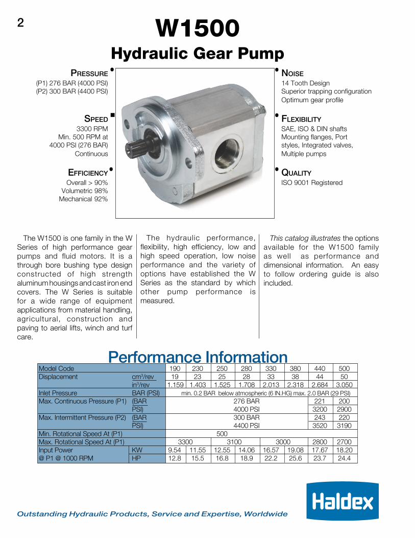
W1500 SERIES HYDRAULIC PUMP
HYDRAULIC SYSTEMS DIVISION Outstanding Hydraulic Products, Service and Expertise, Worldwide
NOISE14 Tooth DesignSuperior trapping configurationOptimum gear profile
FLEXIBILITYSAE, ISO & DIN shaftsMounting flanges, Portstyles, Integrated valves,Multiple pumps
QUALITYISO 9001 Registered
Hydraulic Gear PumpPRESSURE
(P1) 276 BAR (4000 PSI)(P2) 300 BAR (4400 PSI)
SPEED3300 RPM
Min. 500 RPM at4000 PSI (276 BAR)
Continuous
EFFICIENCYOverall > 90%
Volumetric 98%Mechanical 92%
.
. .
.
The W1500 is one family in the WSeries of high performance gearpumps and fluid motors. It is athrough bore bushing type designconstructed of high strengthaluminum housings and cast iron endcovers. The W Series is suitablefor a wide range of equipmentapplications from material handling,agricultural, construction andpaving to aerial lifts, winch and turfcare.
This catalog illustrates the optionsavailable for the W1500 familyas well as performance anddimensional information. An easyto follow ordering guide is alsoincluded.
The hydraulic performance,flexibility, high efficiency, low andhigh speed operation, low noiseperformance and the variety ofoptions have established the WSeries as the standard by whichother pump performance ismeasured.
W1500.
.
Outstanding Hydraulic Products, Service and Expertise, Worldwide
2
Performance InformationModel Code 190 230 250 280 330 380 440 500Displacement cm3/rev 19 23 25 28 33 38 44 50
in3/rev 1.159 1.403 1.525 1.708 2.013 2.318 2.684 3.050Inlet Pressure BAR (PSI) min. 0.2 BAR below atmospheric (6 IN.HG) max. 2.0 BAR (29 PSI)Max. Continuous Pressure (P1) (BAR 276 BAR 221 200
PSI) 4000 PSI 3200 2900Max. Intermittent Pressure (P2) (BAR 300 BAR 243 220
PSI) 4400 PSI 3520 3190Min. Rotational Speed At (P1) 500Max. Rotational Speed At (P1) 3300 3100 3000 2800 2700Input Power KW 9.54 11.55 12.55 14.06 16.57 19.08 17.67 18.20@ P1 @ 1000 RPM HP 12.8 15.5 16.8 18.9 22.2 25.6 23.7 24.4
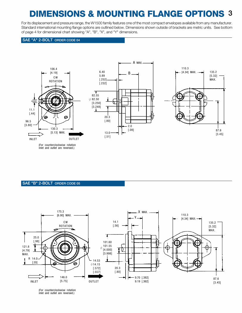
DIMENSIONS & MOUNTING FLANGE OPTIONS 3For its displacement and pressure range, the W1500 family features one of the most compact envelopes available from any manufacturer.Standard international mounting flange options are outlined below. Dimensions shown outside of brackets are metric units. See bottomof page 4 for dimensional chart showing "A", "B", "X", and "Y" dimensions.
SAE "A" 2-BOLT ORDER CODE 04
SAE "B" 2-BOLT ORDER CODE 05
OUTLETINLET
14.5314.15[.572][.557]
C WROTATION
101.60101.55[4.000][3.998]
146.0[5.75]
Y
X MAX.
106.4[4.19]
OUTLETINLET
(For counterclockwise rotationinlet and outlet are reversed.)
C WROTATION
11.1[.44]
96.5[3.80]
130.3[5.13] MAX.
87.6[3.45]
135.2[5.32]MAX.
110.3[4.34] MAX.
175.3[6.90] MAX.
25.0[.98]
121.8[4.79]MAX.
R 14.0 [.55]
14.1[.56]
9.70 [.382]9.19 [.362]
20.3[.80]
87.6[3.45]
135.2[5.32]MAX.
110.3[4.34] MAX.
(For counterclockwise rotationinlet and outlet are reversed.)
A MAX.
B
13.0[.51]
2.0[.08]
20.3[.80]
6.405.89[.252][.232]
82.5582.50[3.250][3.248]
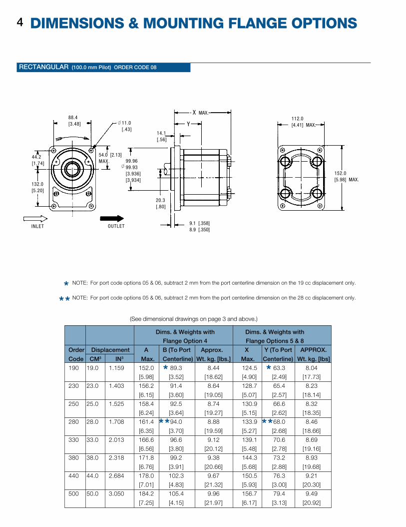
DIMENSIONS & MOUNTING FLANGE OPTIONS4
RECTANGULAR (100.0 mm Pilot) ORDER CODE 08
NOTE: For port code options 05 & 06, subtract 2 mm from the port centerline dimension on the 19 cc displacement only.
NOTE: For port code options 05 & 06, subtract 2 mm from the port centerline dimension on the 28 cc displacement only.***
* *
** **
Dims. & Weights with Dims. & Weights with
Flange Option 4 Flange Options 5 & 8
Order Displacement A B (To Port Approx. X Y (To Port APPROX.
Code CM3 IN3 Max. Centerline) Wt. kg. [lbs.] Max. Centerline) Wt. kg. [lbs]
190 19.0 1.159 152.0 89.3 8.44 124.5 63.3 8.04
[5.98] [3.52] [18.62] [4.90] [2.49] [17.73]
230 23.0 1.403 156.2 91.4 8.64 128.7 65.4 8.23
[6.15] [3.60] [19.05] [5.07] [2.57] [18.14]
250 25.0 1.525 158.4 92.5 8.74 130.9 66.6 8.32
[6.24] [3.64] [19.27] [5.15] [2.62] [18.35]
280 28.0 1.708 161.4 94.0 8.88 133.9 68.0 8.46
[6.35] [3.70] [19.59] [5.27] [2.68] [18.66]
330 33.0 2.013 166.6 96.6 9.12 139.1 70.6 8.69
[6.56] [3.80] [20.12] [5.48] [2.78] [19.16]
380 38.0 2.318 171.8 99.2 9.38 144.3 73.2 8.93
[6.76] [3.91] [20.66] [5.68] [2.88] [19.68]
440 44.0 2.684 178.0 102.3 9.67 150.5 76.3 9.21
[7.01] [4.83] [21.32] [5.93] [3.00] [20.30]
500 50.0 3.050 184.2 105.4 9.96 156.7 79.4 9.49
[7.25] [4.15] [21.97] [6.17] [3.13] [20.92]
(See dimensional drawings on page 3 and above.)
INLET OUTLET
88.4[3.48] Y
152.0[5.98] MAX.
54.0 [2.13]MAX.
44.2[1.74]
132.0[5.20]
14.1[.56]
20.3[.80]
9.1 [.358]8.9 [.350]
112.0[4.41] MAX.
X MAX.
11.0[.43]
99.9699.93[3.936][3.934]
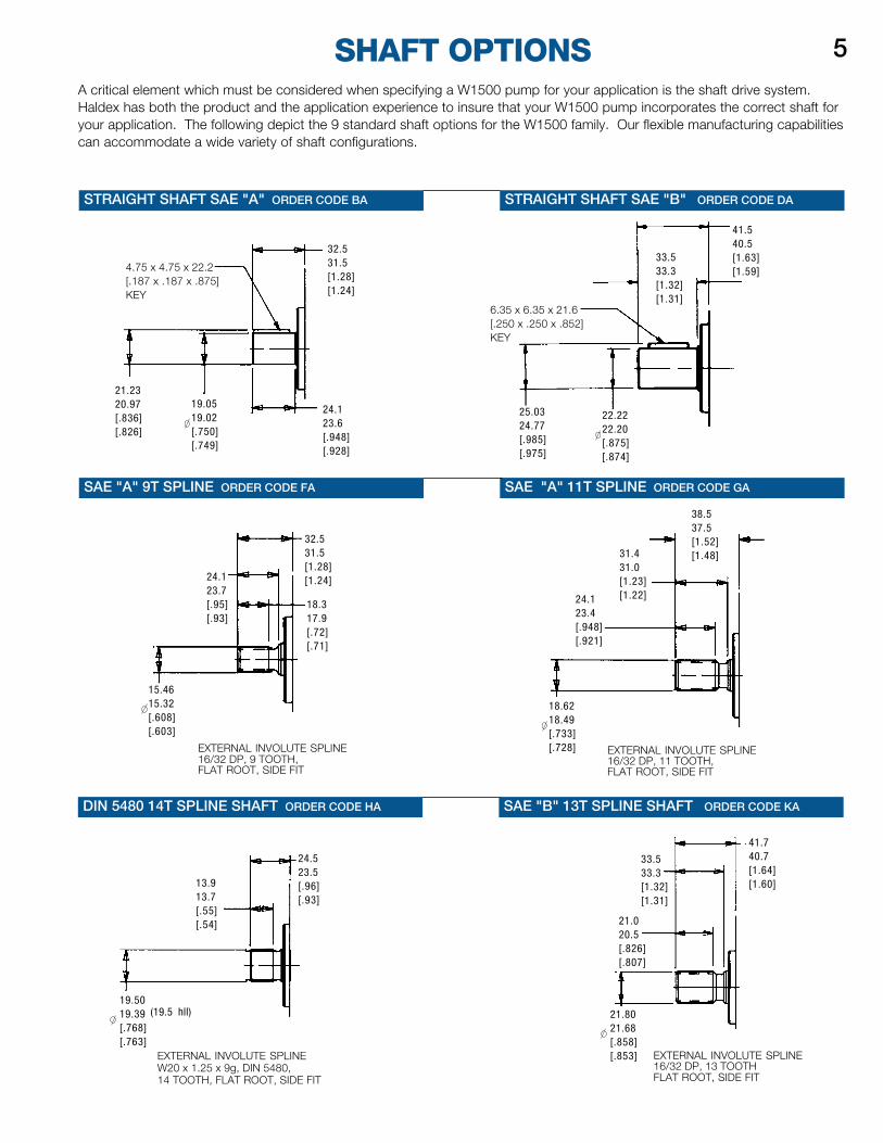
STRAIGHT SHAFT SAE "B" ORDER CODE DA
SAE "A" 11T SPLINE ORDER CODE GA
DIN 5480 14T SPLINE SHAFT ORDER CODE HA
SHAFT OPTIONS 5A critical element which must be considered when specifying a W1500 pump for your application is the shaft drive system.Haldex has both the product and the application experience to insure that your W1500 pump incorporates the correct shaft foryour application. The following depict the 9 standard shaft options for the W1500 family. Our flexible manufacturing capabilitiescan accommodate a wide variety of shaft configurations.
STRAIGHT SHAFT SAE "A" ORDER CODE BA
SAE "A" 9T SPLINE ORDER CODE FA
SAE "B" 13T SPLINE SHAFT ORDER CODE KA
EXTERNAL INVOLUTE SPLINE16/32 DP, 11 TOOTH,FLAT ROOT, SIDE FIT
EXTERNAL INVOLUTE SPLINE16/32 DP, 9 TOOTH,FLAT ROOT, SIDE FIT
EXTERNAL INVOLUTE SPLINEW20 x 1.25 x 9g, DIN 5480,14 TOOTH, FLAT ROOT, SIDE FIT
EXTERNAL INVOLUTE SPLINE16/32 DP, 13 TOOTHFLAT ROOT, SIDE FIT
38.537.5[1.52][1.48]
4.75 x 4.75 x 22.2[.187 x .187 x .875]KEY
21.2320.97[.836][.826]
19.0519.02[.750][.749]
24.123.6[.948][.928]
32.531.5[1.28][1.24]
33.533.3[1.32][1.31]
6.35 x 6.35 x 21.6[.250 x .250 x .852]KEY
25.0324.77[.985][.975]
22.2222.20[.875][.874]
41.540.5[1.63][1.59]
31.431.0[1.23][1.22]24.1
23.4[.948][.921]
18.6218.49[.733][.728]
32.531.5[1.28][1.24]24.1
23.7[.95][.93]
15.4615.32[.608][.603]
18.317.9[.72][.71]
24.523.5[.96][.93]
13.913.7[.55][.54]
19.5019.39[.768][.763]
(19.5 hll)
41.740.7[1.64][1.60]
21.020.5[.826][.807]
33.533.3[1.32][1.31]
21.8021.68[.858][.853]
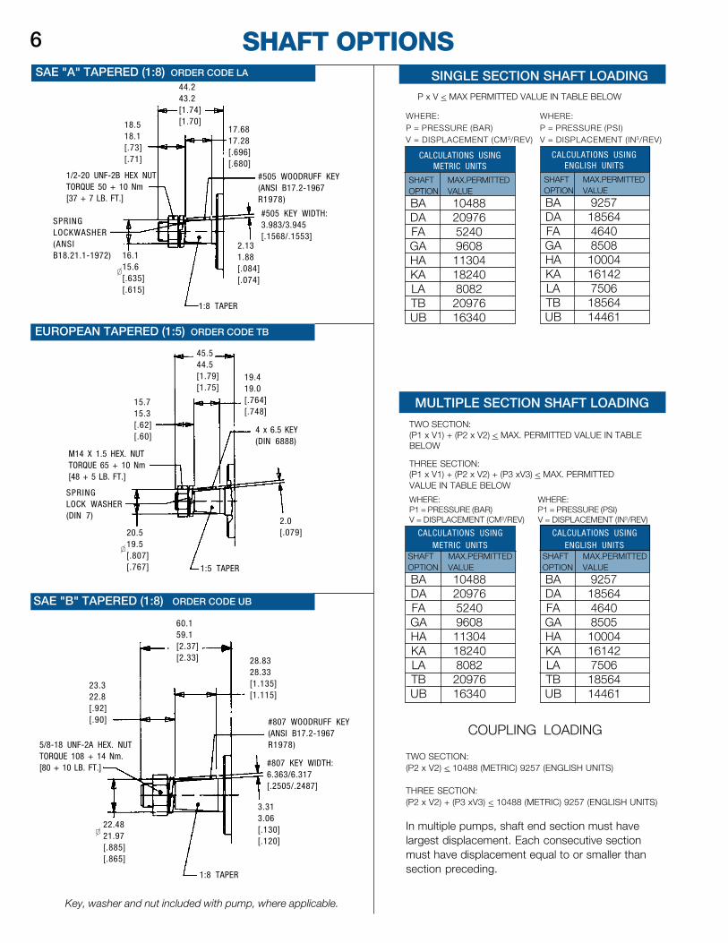
SHAFT OPTIONS6SAE "A" TAPERED (1:8) ORDER CODE LA
EUROPEAN TAPERED (1:5) ORDER CODE TB
SAE "B" TAPERED (1:8) ORDER CODE UB
COUPLING LOADING
TWO SECTION:(P2 x V2) < 10488 (METRIC) 9257 (ENGLISH UNITS)
THREE SECTION:(P2 x V2) + (P3 xV3) < 10488 (METRIC) 9257 (ENGLISH UNITS)
In multiple pumps, shaft end section must havelargest displacement. Each consecutive sectionmust have displacement equal to or smaller thansection preceding.
Key, washer and nut included with pump, where applicable.
MULTIPLE SECTION SHAFT LOADING
TWO SECTION:(P1 x V1) + (P2 x V2) < MAX. PERMITTED VALUE IN TABLEBELOW
THREE SECTION:(P1 x V1) + (P2 x V2) + (P3 xV3) < MAX. PERMITTEDVALUE IN TABLE BELOW
WHERE: WHERE:P1 = PRESSURE (BAR) P1 = PRESSURE (PSI)V = DISPLACEMENT (CM3/REV) V = DISPLACEMENT (IN3/REV)
SINGLE SECTION SHAFT LOADING
P x V < MAX PERMITTED VALUE IN TABLE BELOW
WHERE: WHERE:P = PRESSURE (BAR) P = PRESSURE (PSI)V = DISPLACEMENT (CM3/REV) V = DISPLACEMENT (IN3/REV)
44.243.2[1.74][1.70]
17.6817.28[.696][.680]
18.518.1[.73][.71]
1/2-20 UNF-2B HEX NUTTORQUE 50 + 10 Nm[37 + 7 LB. FT.]
SPRINGLOCKWASHER(ANSIB18.21.1-1972) 16.1
15.6[.635][.615]
1:8 TAPER
2.131.88[.084][.074]
#505 WOODRUFF KEY(ANSI B17.2-1967R1978)
#505 KEY WIDTH:3.983/3.945[.1568/.1553]
45.544.5[1.79][1.75]
19.419.0[.764][.748]
M14 X 1.5 HEX. NUTTORQUE 65 + 10 Nm[48 + 5 LB. FT.]
15.715.3[.62][.60]
SPRINGLOCK WASHER(DIN 7)
20.519.5[.807][.767] 1:5 TAPER
2.0[.079]
4 x 6.5 KEY(DIN 6888)
60.159.1[2.37][2.33]
23.322.8[.92][.90]
5/8-18 UNF-2A HEX. NUTTORQUE 108 + 14 Nm.[80 + 10 LB. FT.]
22.4821.97[.885][.865]
1:8 TAPER
3.313.06[.130][.120]
#807 KEY WIDTH:6.363/6.317[.2505/.2487]
#807 WOODRUFF KEY(ANSI B17.2-1967R1978)
28.8328.33[1.135][1.115]
CALCULATIONS USINGMETRIC UNITS
SHAFT MAX.PERMITTEDOPTION VALUE
BA 10488DA 20976FA 5240GA 9608HA 11304KA 18240LA 8082TB 20976UB 16340
CALCULATIONS USINGENGLISH UNITS
SHAFT MAX.PERMITTEDOPTION VALUE
BA 9257DA 18564FA 4640GA 8508HA 10004KA 16142LA 7506TB 18564UB 14461
CALCULATIONS USINGMETRIC UNITS
SHAFT MAX.PERMITTEDOPTION VALUE
BA 10488DA 20976FA 5240GA 9608HA 11304KA 18240LA 8082TB 20976UB 16340
CALCULATIONS USINGENGLISH UNITS
SHAFT MAX.PERMITTEDOPTION VALUE
BA 9257DA 18564FA 4640GA 8505HA 10004KA 16142LA 7506TB 18564UB 14461
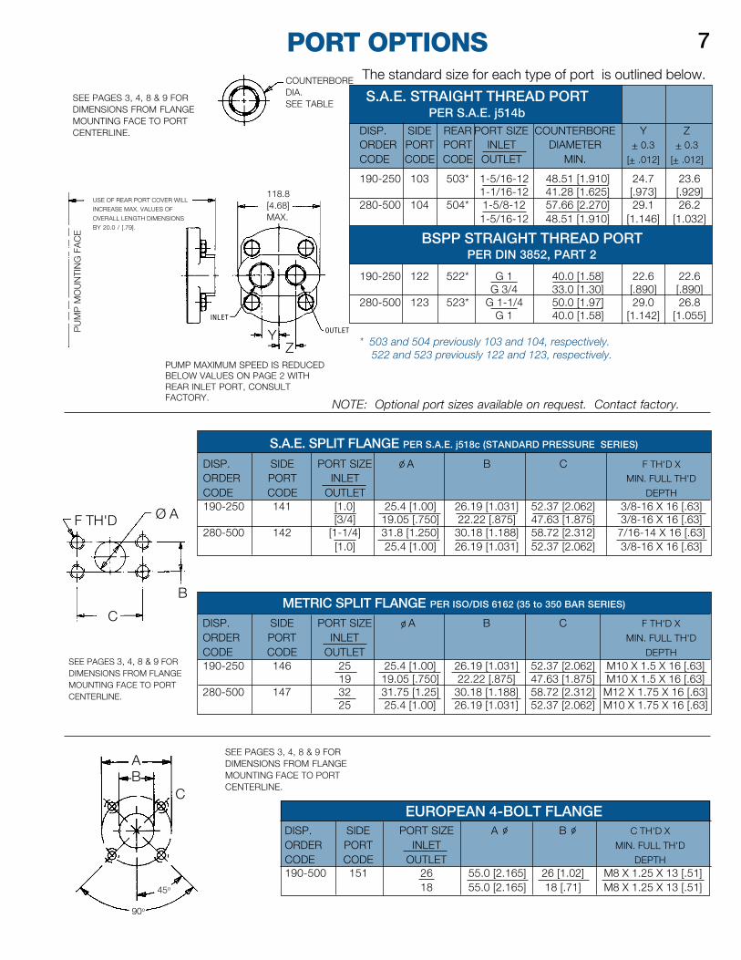
EUROPEAN 4-BOLT FLANGEDISP. SIDE PORT SIZE A B C TH'D X
ORDER PORT INLET MIN. FULL TH'D
CODE CODE OUTLET DEPTH190-500 151 26 55.0 [2.165] 26 [1.02] M8 X 1.25 X 13 [.51]
18 55.0 [2.165] 18 [.71] M8 X 1.25 X 13 [.51]
INLET OUTLET
DISP. SIDE REAR PORT SIZE COUNTERBORE Y ZORDER PORT PORT INLET DIAMETER + 0.3 + 0.3
CODE CODE CODE OUTLET MIN. [+ .012] [+ .012]
190-250 103 503* 1-5/16-12 48.51 [1.910] 24.7 23.61-1/16-12 41.28 [1.625] [.973] [.929]
280-500 104 504* 1-5/8-12 57.66 [2.270] 29.1 26.21-5/16-12 48.51 [1.910] [1.146] [1.032]
190-250 122 522* G 1 40.0 [1.58] 22.6 22.6G 3/4 33.0 [1.30] [.890] [.890]
280-500 123 523* G 1-1/4 50.0 [1.97] 29.0 26.8G 1 40.0 [1.58] [1.142] [1.055]
* 503 and 504 previously 103 and 104, respectively. 522 and 523 previously 122 and 123, respectively.
METRIC SPLIT FLANGE PER ISO/DIS 6162 (35 to 350 BAR SERIES)
S.A.E. SPLIT FLANGE PER S.A.E. j518c (STANDARD PRESSURE SERIES)
BSPP STRAIGHT THREAD PORTPER DIN 3852, PART 2
S.A.E. STRAIGHT THREAD PORTPER S.A.E. j514b
90o
C
AB
45o
PORT OPTIONS
SEE PAGES 3, 4, 8 & 9 FORDIMENSIONS FROM FLANGEMOUNTING FACE TO PORTCENTERLINE.
7
PUMP MAXIMUM SPEED IS REDUCEDBELOW VALUES ON PAGE 2 WITHREAR INLET PORT, CONSULTFACTORY.
SEE PAGES 3, 4, 8 & 9 FORDIMENSIONS FROM FLANGEMOUNTING FACE TO PORTCENTERLINE.
SEE PAGES 3, 4, 8 & 9 FORDIMENSIONS FROM FLANGEMOUNTING FACE TO PORTCENTERLINE.
NOTE: Optional port sizes available on request. Contact factory.
PU
MP
MO
UN
TIN
G F
AC
EThe standard size for each type of port is outlined below.COUNTERBORE
DIA.SEE TABLE
118.8[4.68]MAX.
USE OF REAR PORT COVER WILL
INCREASE MAX. VALUES OF
OVERALL LENGTH DIMENSIONS
BY 20.0 / [.79].
INLET
ZY OUTLET
F TH'D Ø A
B
C
90o
45o
AB
C
DISP. SIDE PORT SIZE A B C F TH'D XORDER PORT INLET MIN. FULL TH'D
CODE CODE OUTLET DEPTH190-250 141 [1.0] 25.4 [1.00] 26.19 [1.031] 52.37 [2.062] 3/8-16 X 16 [.63]
[3/4] 19.05 [.750] 22.22 [.875] 47.63 [1.875] 3/8-16 X 16 [.63]280-500 142 [1-1/4] 31.8 [1.250] 30.18 [1.188] 58.72 [2.312] 7/16-14 X 16 [.63]
[1.0] 25.4 [1.00] 26.19 [1.031] 52.37 [2.062] 3/8-16 X 16 [.63]
DISP. SIDE PORT SIZE A B C F TH'D X
ORDER PORT INLET MIN. FULL TH'D
CODE CODE OUTLET DEPTH190-250 146 25 25.4 [1.00] 26.19 [1.031] 52.37 [2.062] M10 X 1.5 X 16 [.63]
19 19.05 [.750] 22.22 [.875] 47.63 [1.875] M10 X 1.5 X 16 [.63]280-500 147 32 31.75 [1.25] 30.18 [1.188] 58.72 [2.312] M12 X 1.75 X 16 [.63]
25 25.4 [1.00] 26.19 [1.031] 52.37 [2.062] M10 X 1.75 X 16 [.63]
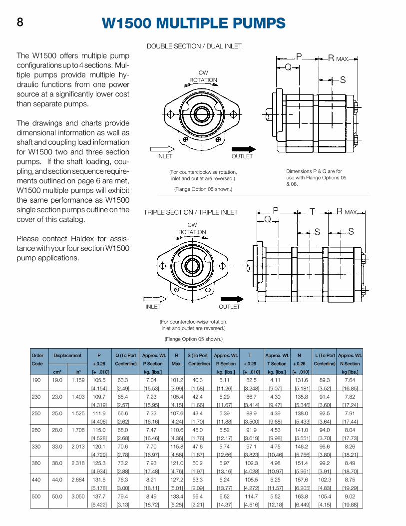
Order Displacement P Q (To Port Approx. Wt. R S (To Port Approx. Wt. T Approx. Wt. N L (To Port Approx. Wt.
Code + 0.26 Centerline) P Section Max. Centerline) R Section + 0.26 T Section + 0.26 Centerline) N Section
cm3 in3 [+ .010] kg. [lbs.] kg. [lbs.] [+ .010] kg. [lbs.] [+ .010] kg [lbs.]
190 19.0 1.159 105.5 63.3 7.04 101.2 40.3 5.11 82.5 4.11 131.6 89.3 7.64
[4.154] [2.49] [15.53] [3.99] [1.58] [11.26] [3.248] [9.07] [5.181] [3.52] [16.85]
230 23.0 1.403 109.7 65.4 7.23 105.4 42.4 5.29 86.7 4.30 135.8 91.4 7.82
[4.319] [2.57] [15.95] [4.15] [1.66] [11.67] [3.414] [9.47] [5.346] [3.60] [17.24]
250 25.0 1.525 111.9 66.6 7.33 107.6 43.4 5.39 88.9 4.39 138.0 92.5 7.91
[4.406] [2.62] [16.16] [4.24] [1.70] [11.88] [3.500] [9.68] [5.433] [3.64] [17.44]
280 28.0 1.708 115.0 68.0 7.47 110.6 45.0 5.52 91.9 4.53 141.0 94.0 8.04
[4.528] [2.68] [16.46] [4.36] [1.76] [12.17] [3.619] [9.98] [5.551] [3.70] [17.73]
330 33.0 2.013 120.1 70.6 7.70 115.8 47.6 5.74 97.1 4.75 146.2 96.6 8.26
[4.729] [2.78] [16.97] [4.56] [1.87] [12.66] [3.823] [10.46] [5.756] [3.80] [18.21]
380 38.0 2.318 125.3 73.2 7.93 121.0 50.2 5.97 102.3 4.98 151.4 99.2 8.49
[4.934] [2.88] [17.48] [4.76] [1.97] [13.16] [4.028] [10.97] [5.961] [3.91] [18.70]
440 44.0 2.684 131.5 76.3 8.21 127.2 53.3 6.24 108.5 5.25 157.6 102.3 8.75
[5.178] [3.00] [18.11] [5.01] [2.09] [13.77] [4.272] [11.57] [6.205] [4.83] [19.29]
500 50.0 3.050 137.7 79.4 8.49 133.4 56.4 6.52 114.7 5.52 163.8 105.4 9.02
[5.422] [3.13] [18.72] [5.25] [2.21] [14.37] [4.516] [12.18] [6.449] [4.15] [19.88]
TRIPLE SECTION / TRIPLE INLET
(Flange Option 05 shown.)
W1500 MULTIPLE PUMPS
The W1500 offers multiple pumpconfigurations up to 4 sections. Mul-tiple pumps provide multiple hy-draulic functions from one powersource at a significantly lower costthan separate pumps.
The drawings and charts providedimensional information as well asshaft and coupling load informationfor W1500 two and three sectionpumps. If the shaft loading, cou-pling, and section sequence require-ments outlined on page 6 are met,W1500 multiple pumps will exhibitthe same performance as W1500single section pumps outline on thecover of this catalog.
Please contact Haldex for assis-tance with your four section W1500pump applications.
8
Dimensions P & Q are foruse with Flange Options 05& 08.
(For counterclockwise rotation,inlet and outlet are reversed.)
R MAX.
(For counterclockwise rotation,inlet and outlet are reversed.)
(Flange Option 05 shown.)
OUTLET
INLET OUTLET
INLET
DOUBLE SECTION / DUAL INLET
CWROTATION
PQ
S
R MAX.
SS
TPQ
CWROTATION
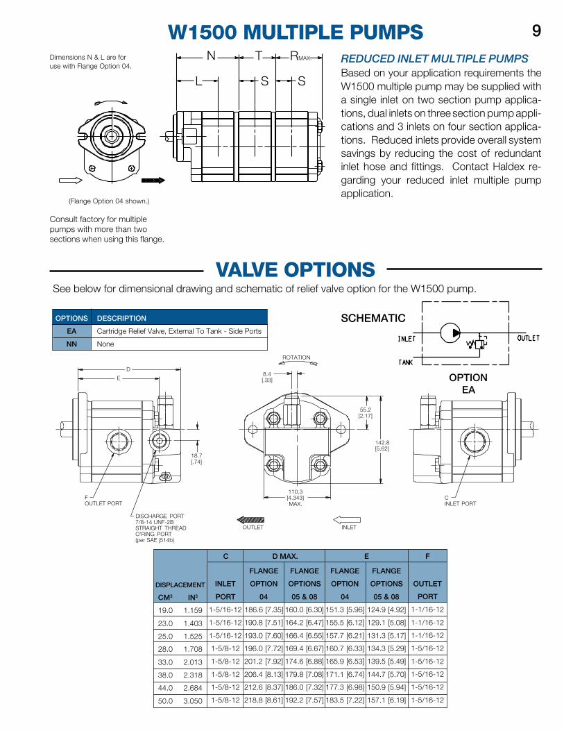
W1500 MULTIPLE PUMPS 9Dimensions N & L are foruse with Flange Option 04.
(Flange Option 04 shown.)
Consult factory for multiplepumps with more than twosections when using this flange.
REDUCED INLET MULTIPLE PUMPSBased on your application requirements theW1500 multiple pump may be supplied witha single inlet on two section pump applica-tions, dual inlets on three section pump appli-cations and 3 inlets on four section applica-tions. Reduced inlets provide overall systemsavings by reducing the cost of redundantinlet hose and fittings. Contact Haldex re-garding your reduced inlet multiple pumpapplication.
VALVE OPTIONSSee below for dimensional drawing and schematic of relief valve option for the W1500 pump.
N
L
T
S S
RMAX.
DESCRIPTION
Cartridge Relief Valve, External To Tank - Side Ports
None
OPTIONS
EA
NN
CINLET PORT
142.8[5.62]
55.2[2.17]
INLETOUTLET
8.4[.33]
ROTATION
18.7[.74]
D
E
FOUTLET PORT
DISCHARGE PORT7/8-14 UNF-2BSTRAIGHT THREADO'RING PORT(per SAE j514b)
110.3[4.343]MAX.
OPTIONEA
ED MAX. F
FLANGE
OPTION
04
151.3 [5.96]
155.5 [6.12]
157.7 [6.21]
160.7 [6.33]
165.9 [6.53]
171.1 [6.74]
177.3 [6.98]
183.5 [7.22]
FLANGE
OPTION
04
186.6 [7.35]
190.8 [7.51]
193.0 [7.60]
196.0 [7.72]
201.2 [7.92]
206.4 [8.13]
212.6 [8.37]
218.8 [8.61]
FLANGE
OPTIONS
05 & 08
160.0 [6.30]
164.2 [6.47]
166.4 [6.55]
169.4 [6.67]
174.6 [6.88]
179.8 [7.08]
186.0 [7.32]
192.2 [7.57]
FLANGE
OPTIONS
05 & 08
124.9 [4.92]
129.1 [5.08]
131.3 [5.17]
134.3 [5.29]
139.5 [5.49]
144.7 [5.70]
150.9 [5.94]
157.1 [6.19]
C
DISPLACEMENT
CM3 IN3
19.0 1.159
23.0 1.403
25.0 1.525
28.0 1.708
33.0 2.013
38.0 2.318
44.0 2.684
50.0 3.050
OUTLET
PORT
1-1/16-12
1-1/16-12
1-1/16-12
1-5/16-12
1-5/16-12
1-5/16-12
1-5/16-12
1-5/16-12
INLET
PORT
1-5/16-12
1-5/16-12
1-5/16-12
1-5/8-12
1-5/8-12
1-5/8-12
1-5/8-12
1-5/8-12
SCHEMATIC
INLET CONDITIONSInlet vacuum should not exceed0.35 Bar below atmospheric pres-sure (10 In.Hg.). Continuous opera-tion at vacuums in excess of 0.2 Barbelow atmospheric pressure (6In.Hg.) are not recommended. Max.gauge pressure for pressurized inletconditions is 2.0 Bar (29 PSI).
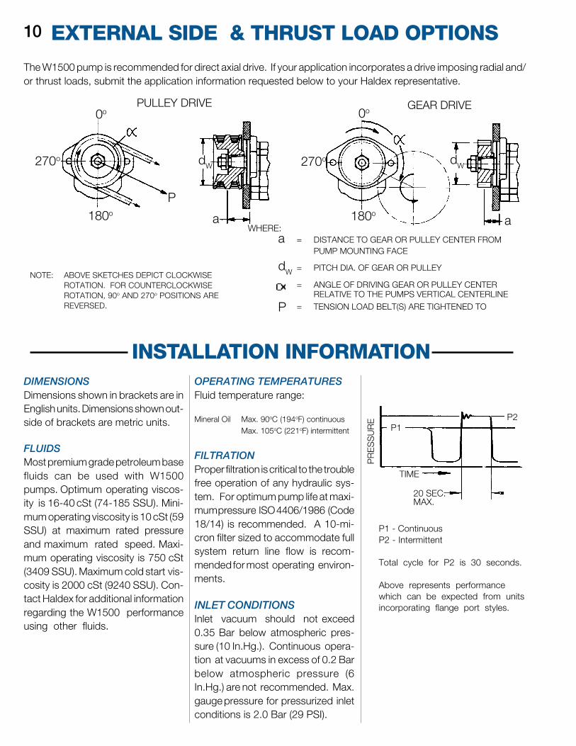
= DISTANCE TO GEAR OR PULLEY CENTER FROMPUMP MOUNTING FACE
= PITCH DIA. OF GEAR OR PULLEY
= ANGLE OF DRIVING GEAR OR PULLEY CENTERRELATIVE TO THE PUMPS VERTICAL CENTERLINE
= TENSION LOAD BELT(S) ARE TIGHTENED TO
The W1500 pump is recommended for direct axial drive. If your application incorporates a drive imposing radial and/or thrust loads, submit the application information requested below to your Haldex representative.
INSTALLATION INFORMATION
NOTE: ABOVE SKETCHES DEPICT CLOCKWISEROTATION. FOR COUNTERCLOCKWISEROTATION, 90o AND 270o POSITIONS AREREVERSED.
EXTERNAL SIDE & THRUST LOAD OPTIONS10
PULLEY DRIVE
WHERE:a
dW
P
PR
ES
SU
RE
GEAR DRIVE
dWdW
DIMENSIONSDimensions shown in brackets are inEnglish units. Dimensions shown out-side of brackets are metric units.
FLUIDSMost premium grade petroleum basefluids can be used with W1500pumps. Optimum operating viscos-ity is 16-40 cSt (74-185 SSU). Mini-mum operating viscosity is 10 cSt (59SSU) at maximum rated pressureand maximum rated speed. Maxi-mum operating viscosity is 750 cSt(3409 SSU). Maximum cold start vis-cosity is 2000 cSt (9240 SSU). Con-tact Haldex for additional informationregarding the W1500 performanceusing other fluids.
OPERATING TEMPERATURESFluid temperature range:
Mineral Oil Max. 90oC (194oF) continuousMax. 105oC (221oF) intermittent
FILTRATIONProper filtration is critical to the troublefree operation of any hydraulic sys-tem. For optimum pump life at maxi-mum pressure ISO 4406/1986 (Code18/14) is recommended. A 10-mi-cron filter sized to accommodate fullsystem return line flow is recom-mended for most operating environ-ments.
P1 - ContinuousP2 - Intermittent
Total cycle for P2 is 30 seconds.
Above represents performancewhich can be expected from unitsincorporating flange port styles.
270o
180o
P
a 180o
270o
0o0o
a
P1P2
20 SEC.MAX.
TIME
Visit our website at http://www.hbus.haldex.com
Call Us Toll Free 1-800-572-7867
Email Us: [email protected] or [email protected]
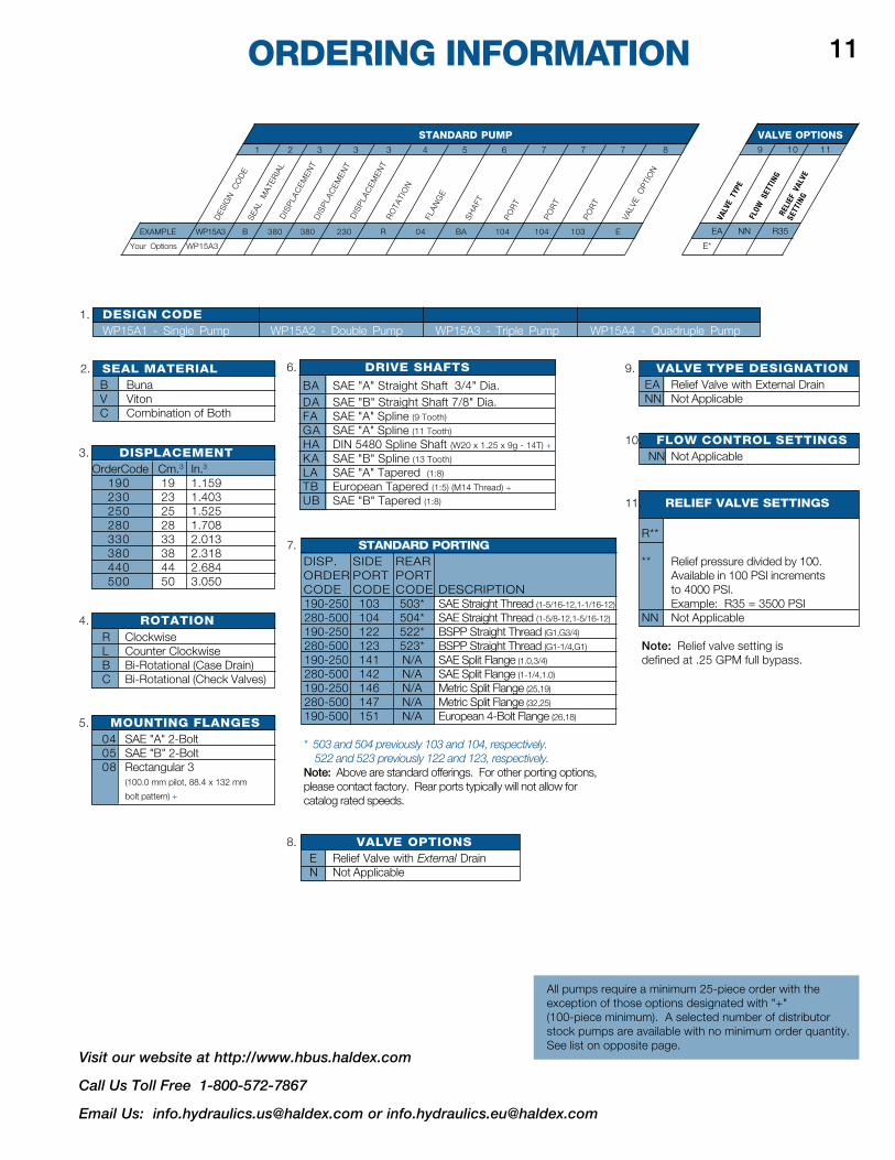
1. DESIGN CODEWP15A1 - Single Pump WP15A2 - Double Pump WP15A3 - Triple Pump WP15A4 - Quadruple Pump
ORDERING INFORMATION
1 2 3 3 3 4 5 6 7 7 7 8
STANDARD PUMP9 10 11
VALVE OPTIONS
VALV
E O
PTIO
N
PO
RT
SEAL
MAT
ERIA
LD
ISP
LAC
EMEN
TD
ISP
LAC
EMEN
TD
ISP
LAC
EMEN
TR
OTA
TIO
N
FLA
NG
E
SH
AFT
PO
RT
PO
RT
RELI
EF V
ALVE
SETT
ING
FLOW
SET
TING
VALV
E TY
PE
DES
IGN
CO
DE
EA NN R35
E*
EXAMPLE WP15A3 B 380 380 230 R 04 BA 104 104 103 E
Your Options WP15A3
11
2. SEAL MATERIALB BunaV VitonC Combination of Both
3. DISPLACEMENTOrderCode Cm.3 In.3
190 19 1.159230 23 1.403250 25 1.525280 28 1.708330 33 2.013380 38 2.318440 44 2.684500 50 3.050
4. ROTATIONR ClockwiseL Counter ClockwiseB Bi-Rotational (Case Drain)C Bi-Rotational (Check Valves)
5. MOUNTING FLANGES04 SAE "A" 2-Bolt05 SAE "B" 2-Bolt08 Rectangular 3
(100.0 mm pilot, 88.4 x 132 mm
bolt pattern) +
7. STANDARD PORTINGDISP. SIDE REARORDER PORT PORTCODE CODE CODE DESCRIPTION190-250 103 503* SAE Straight Thread (1-5/16-12,1-1/16-12)
280-500 104 504* SAE Straight Thread (1-5/8-12,1-5/16-12)
190-250 122 522* BSPP Straight Thread (G1,G3/4)
280-500 123 523* BSPP Straight Thread (G1-1/4,G1)
190-250 141 N/A SAE Split Flange (1.0,3/4)
280-500 142 N/A SAE Split Flange (1-1/4,1.0)
190-250 146 N/A Metric Split Flange (25,19)
280-500 147 N/A Metric Split Flange (32,25)
190-500 151 N/A European 4-Bolt Flange (26,18)
* 503 and 504 previously 103 and 104, respectively. 522 and 523 previously 122 and 123, respectively.Note: Above are standard offerings. For other porting options,please contact factory. Rear ports typically will not allow forcatalog rated speeds.
8. VALVE OPTIONSE Relief Valve with External DrainN Not Applicable
6. DRIVE SHAFTS
BA SAE "A" Straight Shaft 3/4" Dia.DA SAE "B" Straight Shaft 7/8" Dia.FA SAE "A" Spline (9 Tooth)
GA SAE "A" Spline (11 Tooth)
HA DIN 5480 Spline Shaft (W20 x 1.25 x 9g - 14T) +
KA SAE "B" Spline (13 Tooth)
LA SAE "A" Tapered (1:8)
TB European Tapered (1:5) (M14 Thread) +
UB SAE "B" Tapered (1:8)
9. VALVE TYPE DESIGNATIONEA Relief Valve with External DrainNN Not Applicable
10. FLOW CONTROL SETTINGSNN Not Applicable
11. RELIEF VALVE SETTINGS
R**
** Relief pressure divided by 100.Available in 100 PSI incrementsto 4000 PSI.Example: R35 = 3500 PSI
NN Not Applicable
Note: Relief valve setting isdefined at .25 GPM full bypass.
All pumps require a minimum 25-piece order with theexception of those options designated with "+"(100-piece minimum). A selected number of distributorstock pumps are available with no minimum order quantity.See list on opposite page.
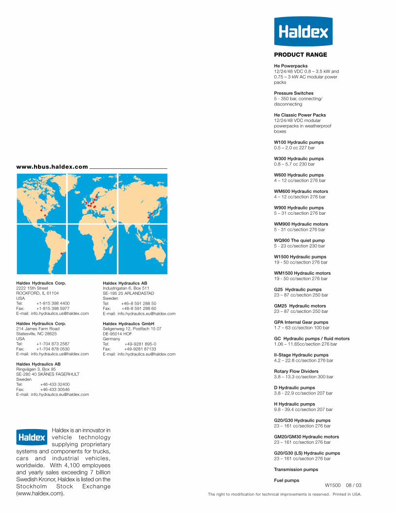
PRODUCT RANGE
www.hbus.haldex.com
Haldex Hydraulics Corp.2222 15th StreetROCKFORD, IL 61104USATel: +1-815 398 4400Fax: +1-815 398 5977E-mail: [email protected]
Haldex Hydraulics Corp.214 James Farm RoadStatesville, NC 28625USATel: +1-704 873 2587Fax: +1-704 878 0530E-mail: [email protected]
Haldex Hydraulics ABRingvägen 3, Box 95SE-280 40 SKÅNES FAGERHULTSwedenTel: +46-433 32400Fax: +46-433 30546E-mail: [email protected]
Haldex Hydraulics ABIndustrigatan 6, Box 511SE-195 25 ARLANDASTADSwedenTel: +46–8 591 288 50Fax: +46-8 591 288 60E-mail: [email protected]
Haldex Hydraulics GmbHSeligenweg 12, Postfach 15 07DE-95014 HOFGermanyTel: +49-9281 895-0Fax: +49-9281 87133E-mail: [email protected]
He Powerpacks12/24/48 VDC 0.8 – 3.5 kW and0.75 – 3 kW AC modular powerpacks
Pressure Switches5 - 350 bar, connecting/disconnecting
He Classic Power Packs12/24/48 VDC modularpowerpacks in weatherproofboxes
W100 Hydraulic pumps0.5 – 2.0 cc 227 bar
W300 Hydraulic pumps0.8 – 5.7 cc 230 bar
W600 Hydraulic pumps4 – 12 cc/section 276 bar
WM600 Hydraulic motors4 – 12 cc/section 276 bar
W900 Hydraulic pumps5 – 31 cc/section 276 bar
WM900 Hydraulic motors5 - 31 cc/section 276 bar
WQ900 The quiet pump5 - 23 cc/section 230 bar
W1500 Hydraulic pumps19 - 50 cc/section 276 bar
WM1500 Hydraulic motors19 - 50 cc/section 276 bar
G25 Hydraulic pumps23 – 87 cc/section 250 bar
GM25 Hydraulic motors23 – 87 cc/section 250 bar
GPA Internal Gear pumps1.7 – 63 cc/section 100 bar
GC Hydraulic pumps / fluid motors1.06 – 11.65cc/section 276 bar
II-Stage Hydraulic pumps4.2 – 22.8 cc/section 276 bar
Rotary Flow Dividers3.8 – 13.3 cc/section 300 bar
D Hydraulic pumps3.8 - 22.9 cc/section 207 bar
H Hydraulic pumps9.8 - 39.4 cc/section 207 bar
G20/G30 Hydraulic pumps23 – 161 cc/section 276 bar
GM20/GM30 Hydraulic motors23 – 161 cc/section 276 bar
G20/G30 (LS) Hydraulic pumps23 – 161 cc/section 276 bar
Transmission pumps
Fuel pumpsW1500 08 / 03
The right to modification for technical improvements is reserved. Printed in USA.
Haldex is an innovator invehicle technologysupplying proprietary
systems and components for trucks,cars and industrial vehicles,worldwide. With 4,100 employeesand yearly sales exceeding 7 billionSwedish Kronor, Haldex is listed on theStockholm Stock Exchange(www.haldex.com).