Embed Size (px)
Citation preview

_____ ____
X-716-6b36'-
WA lx~b367
REVIEW Of LIQUID-METAL MAGN ETOHYDRODYNAM IC
ENERGY CONVERSION CYCLES
FREDERICK H. MORSE
AUGUST 1 , , t
GODDARD SPACE FLIGHT CENTER GREENBELT, MARYLAND
Reprodu Id b h .. .N69-37703 CoCLEARINGHoUSE
, = _fo Federa Scintific & Technical .ACCSStONNUM ER) r(HFU) Information Springfield Va. 22151
WAGES)(CODE)
03 (NASA COROR TNX OR AD NUMBER) (CATEGORY)
https://ntrs.nasa.gov/search.jsp?R=19690028325 2020-04-01T03:51:02+00:00Z

X-716-69-365
REVIEW OF LIQUID-METAL MAGNETOHYDRODYNAMIC ENERGY CONVERSION CYCLES*
Frederick H. Morse**
August 1969
*This work was performed under the NASA-ASEE Summer Faculty Program **Assistant Professor, Department of Mechanical Engineering, University of Maryland
GODDARD SPACE FLIGHT CENTER Greenbelt, Marjlid

ABSTRACT
Interest in liquid-metal magnetohydrodynamic (LM-MHD) power generation has developed because of its high power density, its ability to operate both AC and DC generators, and the possibility of operation at moderate temperatures. Recent efforts and advances in LM-MHD have made the evaluation of such systems for spacecraft power supply feasible. In this report all of the reported LM-MHD power generation cycles are described and their efficiencies compared. A brief summary of the evolution and status of the LM-/HD power generation systems and a listing of facilities engaged in LM-MHD is also included.
Il LNKNlTFLMD

CONTENTS
Page
ABSTRACT .......... ......................... ..
INTRODUCTION ........... ......................... 1
Energy Conversion ........ .................. ....... 1
Status of LM-MHD Systems
TABLES
......... .................. 2 Research Facilities ........... .................... 5
LIQUID-METAL MHD SYSTEMS ........ .................. 6
Introduction ............. ........................ 6 Fog FlowSystems ............. ................. 9
Separator ......... ......................... ... 11 Injector-Condenser .................... 23
Two-Phase Flow ....... ..................... ..... 38
Emulsion Flow ............. ................. 38 Slug Flow ........... ...................... ... 44
SUMMARY .......... ............................ ... 46
REFERENCES ......... ....................... ... . 48
Table Page
1 Listing of Facilities Engaged in Liquid-Metal MD Research ............. ....................... 7
2 Liquid-Metal MIHD Systems Presently Under Investigation . . . 10
3 Predicted Maximum Efficiency for Liquid-Metal MHD Cycles ........... ............. ..... 47
V

ILLUSTRATIONS
Figure Page
1 Percentage of Liquid-Metal and Related Papers Presented at SymposiaDuring the Years 1962 to 1969 ....... 5
2a Single-Component Separator Cycle ...... ............. 12
2b Temperature vs Entropy Diagram for a Single-Component Separator Cycle ............... . .. ............ .. 13
3a Single-Componetit Separator Cycle with Downstream Mixing ............. .......... ...... 14
3b Temperature vs Entropy Diagram for a Single-Component Separator Cycle with Down-Stream Mixing .. ......... ... 15
4a Single-Component Separator Cycle with Partial Separation 16
4b Temperature vs Entropy Diagram for a Single-Component Separator Cydle with Partial Separation ... ......... ... 17
5a Single-Component Multistage Separator Cycle with Regenerative Heating .......... .................. 19
5b Temperature vs Entropy Diagram for a Single-Component Multistage Separator Cycle with Regenerative Heating . . . . 20
6 Two-Component Separator Cycle ..... ............. ... 21
7 Two-Component Multistage Separator Cycle .. ......... ... 22
Sa Single-Component Injector-Condenser Cycle... . . .... 24
8b Temperature vs Entropy Diagram for a Single-Component
Injector-Condenser Cycle ...... ................. ... 25
9a Single-Component Injector-Condenser Cycle with Partial Preheating ........ ..................... .... 27
9b Temperature vs Entropy Diagram for a Single-Component Injector-Condenser Cycle with Parti~l Preheating . ..... 28
vi
ILLUSTRATIONS (Continued)
Figure Page
10a 'Single-Component Injector-Condenser Cycle with Preheating .................... ........... .. 29
Iujector-Condenser Cycle with Multistage Injection and
10b Temperature vs Entropy Diagram for a Single-Component Injector-Condenser Cycle with Preheating .. ......... ... 30
11 Single-Component Injector-Condenser Cycle with Regeneration ........ ..................... .... 31
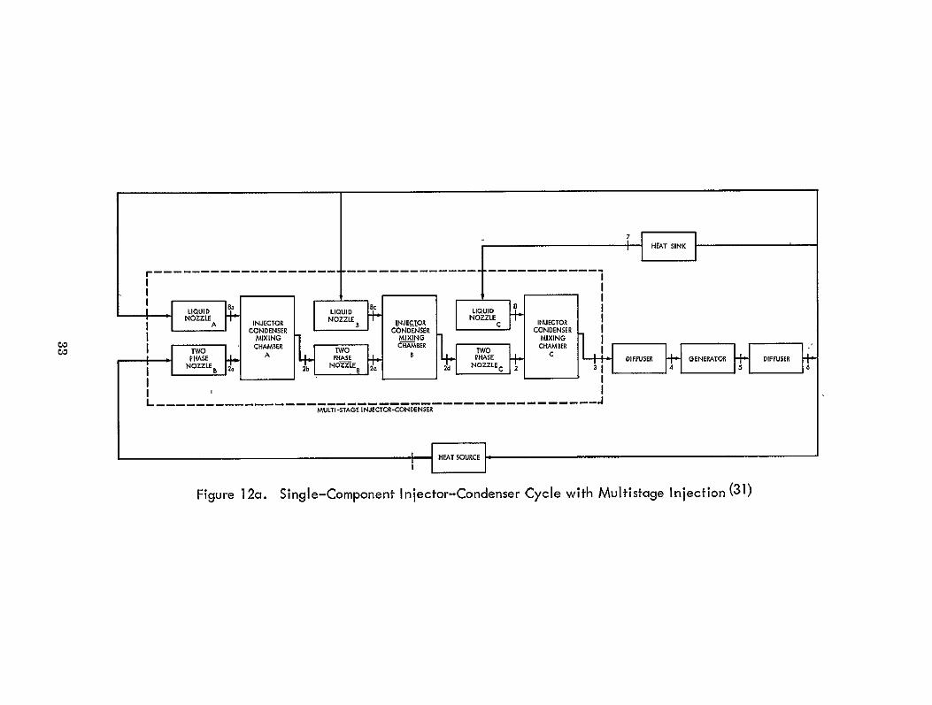
12a Single-Component Injector-Condenser with Multistage Injection ......... ....................... .... 33
12b Temperature vs Entropy Diagram for a Single-Componeht Injector-Condenser Cycle with Multistage Injection .. ... 34
13a Single-Component Injector-Condenser with Multistage Injection and Generation ... ............ . ...... 35
13b Temperature vs Entropy Diagram for a Single-Component
Generation ........... .................. ... 36
14 Two-Component Injector-Condenser Cycle .... ......... 37
15 Two-Component Injector-Condenser Cycle with Regeneration ........ ...................... ... 39
16a Single-Component Emulsion Flow Cycle ..... .......... 40
16b Temperature vs Entropy Diagram for a Single-Component Emulsion Flow Cycle ...... ................... ... 41
17 Single-Component Emulsion Flow Cycle with Simultaneous Generation and Separation ...................... ... 43
18 Two-Component Emulsion Flow Cycle ..... ......... 44
19 Single-Component Slug Flow Cycle ... ........... .... 45
vii

REVIEW OF LIQUID-METAL MAGNETOHYDRODYNAMIC ENERGY CONVERSION CYCLES
INTRODUCTION
Energy Conversion
Many of the proposed space missions require the development of efficient, light-weight, compact power systems. At low power levels, of the order of watts, solar cells and thermoelectric converters with radioisotope heat sources are now used. For higher power levels Rankine and Brayton cycles using turboalternators are under various stages of hardware development. However, the uppermost interest is in space power systems which do not incorporate moving mechanical parts, since these are potentially more reliable and have longer lifetime capabilities. Energy conversion systems employing the sun, nuclear reactors or isotopes as thermal energy sources coupled with thermionic, thermoelectric or magnetohydrodynamic devices are in this class. In the MIHD devices, electrical power is generated by forcing a conducting fluid - a liquid metal such as potassium, cesium, lithium, sodium, or mercury through a magnetic field.
Interest in liquid metal magnetohydrodynamic (LM-MHD) power generation has arisen because of the high power density, which makes operation with modest magnetic fields possible, the large magnetic Reynolds number which makes AC power generation possible, and the possibility of operation these systems at moderate temperatures (11000 -1400'K). Recent efforts and advances (1, 2, 3, 4) in the field of LM-MHD have made evaluation of such systems for spacecraft power supply feasible.
In contrast to a Rankine (or Brayton) cycle which uses the vapor (or gas) phase as the working fluid, LV1-MHD cycles must transfer the thermal energy of a vapor phase into kinetic energy or stagnation pressure of a fluid (liquid or mixture) of sufficient electrical conductivity to adequately interact with the magnetic field in the MIIHD generator. Consistent with this constraint, a number of LM-MHD energy conversion systems have been proposed. All of these systems are based on a common cycle using a two-phase flow. The thermal energy of the working fluid is increased by the heat source. A fraction of the thermal energy of the fluid is converted into kinetic energy which, in turn, is partially converted into electrical energy in the MHD generator. The remaining thermal energy is rejected in the heat sink and the fluid returns to the heat source to complete the cycle. The various proposed LM-IVMHD systems differ in the method of converting the thermal energy to kinetic energy, the particular two-phase flow regime utilized, the method for recovering pressure, and the
1

MHD generator configuration. The heat source for space applications would be a nuclear reactor while for terrestrial applications the additional possibility of coupling to a fossil fuel heat source also exists.
There are three broad problem areas to be considered in the application of LM-MHD systems:
1. Efficient cycles must be developed in terms of selection of components and working fluids.
2. Efficient generators must be developed, either AC or DC type.
3. Efficient means of accelerating the working fluid must be developed.
This report will describe and compare the proposed LM-MHD cycles and summarize the present state of their development. Preceeding this review a brief report on the evolution and status of LM-MHD power generation systems will be presented.
Status of LM-MED Systems
Every two years since 1962 an International Symposium on lVfagnetohydrodynamic Electrical Power Generation has convened to assess the standing and future prospects of MHD. It will be convenient to base a review of the progress made in liquid metal MIHD on the work reported on at these meetings.
The liquid metal MHD energy conversion concept was introduced (5) at the first International Symposium on MED Electrical Power Generation in 1962. (1) Two years later at the Second International Symposium (2) five papers pertaining to LM-MHD were presented, two reporting on preliminary design considerations and experimental studies of induction LM-MHD generators (6, 7) and three describing energy conversion systems. (8, 9, 10) It was understandable that much of this early work was concerned with devising energy conversion cycles and establishing a thermodynamic theory for them. At this symposium the basic emulsion and injector-condenser cycles* were introduced and several modifications of these cycles were proposed. The basic separator cycle had already been introduced. (11) One objective, as in any thermodynamic energy conversion cycle, was to achieve the highest thermodynamic efficiency. Cycle efficiencies (with a maximum cycle temperature of approximately 1370 0K) ranging from 814% were predicted at this time. The cycle efficiency depends not only on the
*These cycles and others are described in the section beginning on page 6.
2

working fluid but on the efficiency of both the LM-MHD generator and the acceleration process. It was realized at this time that the design of an efficient liquid metal accelerator was likely to present the most serious problems.
I
In the interval between the second and the third symposia work continued on cycle improvements and generator performance. In addition, attention was being focused on the details of the acceleration process. In 1965, the impedance characteristics of an induction generator operating in a NaK loop were measured. In that same year electrical power output was obtained from an externally excited generator operating in a NaK blow-down facility. In 1966, prior to the Third International Symposium, the operation of generators independent of external excitation was achieved.
At the Third International Symposium (3) twenty papers on various aspects of LM-MlHD were presented. The session on LM-MHD was divided into three catagories: liquid acceleration (7 papers), generators (8 papers) and cycles (5 papers).
In the area of liquid acceleration work was reported on the experimental and theoretical investigation of various types of two-phase flow, on nozzles and diffusers, on separation and on mixing and condensation phenomena in jets. In spite of this effort, however, the design of an efficient liquid metal accelerator had not been accomplished. Additional research was required.
Preliminary experimental data were presented for the several small LM-MHD generators that had been built. Two main types of generators were being developed: an AC induction generator and a DC generator operating on a twophase mixture. The AC generator was a linear version of a conventional induction machine. The first model was built and tested in 1964 by Jackson's group at MIT. (6) This was followed by a generator, built by Prems 's group at Atomics International, which produced 1. 84kw at 215 v and 350 Hz, with an electrical efficiency of 30% (12). An electrical efficiency of approximately 70% was predicted by extrapolating the data to a large-scale generator. Another generator tested produced 1.0kw at 210v and 50Hz.( 13 ) A major improvement was the introduction of the short-wavelength machine with compensating poles to reduce end losses. (14) Some testing was conducted on DC generators operating with twophase mixtures, (15, 16, 17) however, additional studies on the influence of void fraction on performance stability, etc. were indicated.
Additional modifications were made of the basic separator, injectorcondenser and emulsion cycles. The predicted cycle efficiency of 8% for the twocomponent separator system seemed most reliable. (14) The best estimates for the injector-condenser cycle efficiency ranged from 8% to lower values. Both of these values were low primarily because of frictional losses.
3

Thus approximately four years after the LM-MHD generator was first discussed, three of the four basic cycles were defined and analyzed and the successful operation of the induction generator operating on a liquid metal flow had been demonstrated.
The Fourth International Symposium (4) reflected the growth of the research and development efforts in liquid metal MI-D energy conversion. Forty papers pertaining to LM-MIHD were presented, representing twenty percent of the entire symposium. Figure 1 shows the percent of conference papers that pertain to LM-MHD as a function of year since 1962. Both the International Symposium on MIHD Electrical Power Generation and the symposiums on Engineering Aspects of Magnetohydrodynamics held annually in the United States are included. Using the number of papers presented at these symposia as a guide, it appears that by 1970 approximately one third of all MIHD research will involve liquid metal systems. This observation is compatible with the recommendation of the Panel on Magnetohydrodynamics (18) that LM-MHD systems analyses and experimental programs be funded at about half the level of support for open-cycle plasma MIHD systems.
Of theforty papers presented at the 1968 International Symposium, sixteen pertained to generators, seventeen pertained to fluid acceleration, and seven pertained to cycle and over-all systems.
Having established the principles of LM-MIHD generator operation the emphasis shifted towards designing efficient long-lived machines. The main objective of these designs and related studies was to achieve substantial improvements in efficiency. The induction generator received the most attention although DC generation was also studied. For the AC induction generator the major subject reported on was the reduction of end losses. (19) A most significant result was that the predicted efficiency of a compensated generator ranged from 63% for a 325kw output to 86%for a 40mw output. (20) Several experimental studies of AC induction generators were reported on with measured efficiencies ranging from 4 to 30%. Experimental results with DC generators yielded higher efficiencies; one such generator operated on a sodium jet at efficiencies of 60 to 70% (21), a compensated NaK generator operated at an efficiency of 70%'(22), and a small emulsion flow generator achieved efficiencies of 40 - 60% (17). At this symposium a new type of generator was introduced; the AC synchronous generator (23).
The problem of accelerating a liquid metal to velocities necessary for MHD power generation remained in spite of considerable efforts. The source of this problem was the high friction losses that occur in separators and injectors. Studies of separators and injectors were aimed at establishing the conditions under which the losses could be minimized.
4

35
zo INTERNATIONAL SYMPOSIA [ NATIONAL SYMPOSIA
03 0
0
Z/ 25 -/
CL
z 2 - 0
Z 15-"
IUU_ Z0LU
U 10 0Lu aZ 5
0Z
C
1962 63 64 65 66 67 68 69 70
YEAR
Figure I1. Percentage of Liquid-Metal and Related Papers Presented at Symposia During the Years 1962 to 1969.
A variety of modifications of the basic LM-M HD cycles were reported on this symposium. The most significant development was the increase in predicted cycle efficiencies from 8 - 14% to 10 - 207o by nmultistaging (24), preheating (25), or the use of two-component emulsions (22). Also introduced at this symposium was the fourth basic cyle - the slug flow cycle (23). The details of
these modifications and the slug flow cycle will be covered in the following chapter.
Research Facilities
There are approximately thirty-four government agencies and private organizations working on L1M-MHD for space, military, nautical and central
5

power plant applications in this country and Europe. Using the number of papers presented at both national and international MHID conferences as a guide, the total European effort in LM-MHD appears to be considerably greater than that of the United States. Of the several European countries involved in this work, the USSR appears to be the most active, at least in presenting papers and in the number of facilities engaged in LM-MHD, with West Germany a close second. Table 1 presents a listing of the research facilities presently active in LM-MHD work. Included in this table are funding agencies (where known) and, for those centers conducting experimental work, the type of facility being used.
LIQUID-METAL MHD SYSTEMS
Introduction
The requirement of the transfer of thermal energy of the vapor phase into kinetic energy of a sufficiently conductive fluid has given rise to four basic LM-MHD cycles:
1. Separator cycle
2. Injector-condenser cycle
3. Emulsion cycle
4. Slug flow cycle
The first two cycles involve a two-step conversion in which the MHD generator operates on kinetic energy that is derived from the conversion of thermal energy prior to entering the generator. A vapor is used to accelerate a liquid metal and then the vapor is either separated or condensed. The extraction of electrical energy from the liquid metal is the second separate step. In the last two cycles the working fluid may be either a homogeneous (emulsion) or an inhomogenous (slug) two-phase flow mixture, and the conversion of thermal to electrical energy is accomplished without an intermediate separation or conversion step. That is, the accelerated two-phase mixture passes directly through the generator.
Three two-phase flow regimes may be utilized in LM-MHD systems-. They are fog flow - small liquid droplets dispersed in a gaseous phase, emulsionflow-small gas bubbles in a liquid metal, and slug flow - large slugs of liquid metal separated by large bubbles. The liquid and gaseous phases may involve the same substance or a two component mixture may be used. In all three regimes the acceleration of the liquid is achieved by the gaseous phase while the conductivity is attributed to the liquid.
6

Table 2 shows the various combinations of flow regime, number of components, type of cycle and number of steps in the energy conversion process of the LM-MHD systems presently under investigation. The major emphasis to date has been placed on those systems operating in the fog-flow regime. Both the one-component injection and two-component separation systems are being investigated in the USA, USSR and Germany and several have reached the operational stage. Both of these systems are of the two-step energy extraction method, utilizing AC asynchronous generators.
The emulsion flow system has been studied in the USA and in France. It involves a one-step energy extraction with a DC generator. The slug flow scheme, investigated in the USA and the USSR, has received the least attention but has been recognized to have the advantage of efficient thermodynamic operation coupled with the possibility of operating a synchronous-type AC generator.
Much of the work to date has been involved in exploring the characteristics of LM-1VIHD systems classified as in Table 2 in an attempt to ascertain which particular system is the most efficient energy converter. These systems will be discussed in the following sections and their predicted efficiencies compared.
Fog Flow Systems
The most extensively studied LM-MHD cycles operate in the fog-flow regime. All cycles of this type use a vapor to accelerate the liquid metal and then the vapor is either separated or condensed. Many scientific and engineering problems associated with the acceleration process remain to be solved.
Two acceleration devices have been examined, separators and injectorcondensers. In the separator mode of operation, the liquid metal to be accelerated is mixed with a gas or vapor before its expansion in a two-phase nozzle. After achieving the required velocity the mixture is passed through a separator where the vapor is separated from the liquid while the kinetic energy of liquid is undiminished. In the injector-condenser mode of operation the liquid metal is mixed with the vapor after its acceleration in the nozzle. The liquid is accelerated and condensed by the vapor making separation unnecessary. The generation of electrical power from the high speed liquid stream takes place in the generator in a separate operation. Systems based on these acceleration processes may employ either a one- or two-component working fluid.
In the following sections the basic one- and two-component separator and injector-condenser cycles are described, and the various modifications that have been proposed to improve the performance of these basic cycles are discussed.
PRECEDING PAGE BLANK NOT FILMED. 9

Table 2 Liquid-Metal MHD Systems Presently Under Investigation
ENUMBER OFCOMPONENTS
ONE
FOG FLOW
C TWO
ONE
TWO-PHASE FLOW,
TWO
CYCLE SINGLE STEP CONVERSION
(NO INTERMEDIATE SEPARATION OR CONDENSATION)
TWO STEP CONVERSION (INTERMEDIATE SEPARATION
OR CONDENSATION)
SEPARATOR JPL, JKC, KPI, HTI
INJECTOR-CONDENSER
BTU-2, JPL, HTI, AEG, BTU-1, MIT, IT
SEPARATOR JPL,HTI
INJECTOR-CONDENSER
JPL, Al, HTI
EMULS ION ANL, DAC
SLUG BNL, MTI
EMULS ION CEM, ANL
SLUG HTI, IEK, IHP

Separator
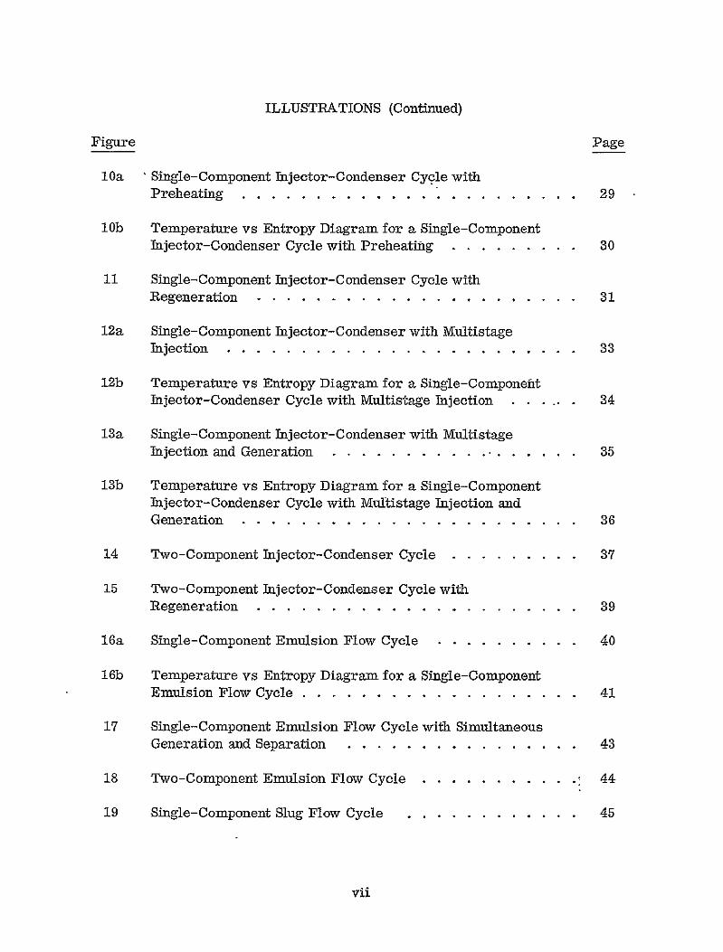
The most elementary separator cycle utilizes one-component. This cycfe is shown schematically in Figure 2a and thermodynamically in Figure 2b. In this cycle the vapor is condensed in the heat sink and is pumped to the mixing chamrber, where it combines with a two-phase fluid from the heat source. The resulting two-phase mixture is accelerated in the nozzle. The vapor is separated from the liquid metal in the separator and returned to the heat sink. The liquid leaves the separator at a high velocity (100-200 m/sec), decelerates in the MHD generator to produce electrical power, and after flowing through a diffuser, it returns to the heat source where it is partially vaporized. Cesium and potassium are the most commonly considered components. The maximum efficiency of a potassium separator cycle operating with a maximum cycle temperature of 1370°K is 3% while that of a cesium separator cycle is 4%. (26) This low efficiency is due to non-isothermal heat addition as well as kinetic energy losses in the separator.
Several modifications of the single-component separator cycle have been proposed:
a. Mix immediately downstream of generator (27)
b. Operate separator so as to yield partial separation (28)
a. Multistage separation with regeneration (29)
d. Two-component working fluid (11)
These modifications will be reviewed in the remainder of this section.
a. Downstream mixing
A distinguishing feature of the separator cycle is that after condensation in the heat sink, the condensate is mixed with the main liquid stream from the heat source. This reduces the enthalpy difference across the nozzle and the acceleration is accordingly reduced. In addition, mixing of the two phases occurs upstream of the nozzle at the maximum cycle pressure. It is therefore necessary to pump the condensed vapor back to the mixing chamber.
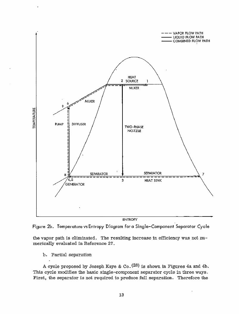
In a modification recently proposed by Aladjev (27) the mixing chamber is placed immediately downstream of the generator, as shown in Figure Sa. A temperature-entropy diagram for this cycle is shown in Figure 3b. The vapor phase is condensed and immediately mixed with the liquid emerging from the diffuser. As a consequence of this arrangement the temperatures of the two components are essentially equal at the mixing point. In addition, the mixing occurs at the minimum pressure point in the cycle and the need for a pump in
11

9-
VAPOR
PATH
-7
MIXER I' NOZE I SEPARA'TOR
PATHt
GENERATOR DIFFUSER
1 6-
SOURE
Figure 2a. Sing le-Component Separator Cycle
---- VAPOR FLOW PATH LIQUID FLOW PATH COMBINED FLOW PATH
2 HEAT
SOURCE I
I-I
MIXE
PUMP I DIFFUSER I TWO-PHASENOZZLE
...... SEPARATOR _ SEPARATOR7 GENERATORSIN
ENTROPY
Figure 2b. Temperature vs Entropy Diagram fora Single-Component Separator Cycle
the vapor path is eliminated. The resulting increase in efficiency was not numerically evaluated in Reference 27.
b. Partial separation
A cycle proposed by Joseph Kaye & C)o. (28) is shown in Figures 4a and 4b.
This cycle modifies the basic single-component separator cycle in three ways. First, the separator is not required to produce full separation. Therefore the
13

-- ~ NIIEAT S rn
8 VAPOR
PATH - 7
]TWO PHASEI 1t
LIQUID PATH
HEA6
SOURCE
Figure 3a. Sing le-Component Separator Cycle with Down-Stream Mixing (27)
- - - VAPOR FLOW PATH -- LIQUID FLOW PATH -
_
COMBINED FLOW PATH
HEAT
2
~DIFFUSER TWO -PHASE NOZZLE
MIXER SEPARATOR
3, 4,5,8 GENERATOR
2
SEPARATOR HEAT SINK
ENTROPY
Figure 36. Temperature vs Entropy Diagram for a Single-Component Separator Cycle with Down-Stream Mixing (27)
large kinetic energy loss in the separator is reduced with an accompanying increase in cycle efficiency. Second, by varying the degree of separation the quality of the low quality stream (the liquid stream in the basic cycle) may be changed, which, in turn, changes its stagnationtemperature. In this way the temperature of the liquid entering the generator can be varied between the maximum and minimum cycle temperatures. This is advantageous because some of the material problems associated with high-temperature liquid-inetal systems can be lessened. Third, the heater in the vapor line permits mixing at close to
15

10 8
HETER DIFFUSER
SOURCE I NOZZLE I+
VAPOR PATH
7
LIQUID
PAT H
Figure 4a. Single-Component Separator Cycle with Partial Separation (28)

- --- VAPOR FLOW PATH LIQUID FLOW PATH
-COMBINED FLOW PATH
~GENERATOR
HEAT SOURCE 3
1 2MIXER11 TWO-PHASE
• NOZZLE
DIFFUSER
SEPARATOR SEPARATOR
4 7
ENTROPY
Figure 4b. Temperature vs Entropy Diagram for a Single-Component Separator Cycle with Partial Separation ( 8)
equal temperatures thereby reducing thermal mixing losses. In addition a larger fraction of the energy supplied by the heat source is at the maximum cycle temperature.
The result of the modifications proposed by Joseph Kaye & Co. (28) is a considerable increase in cycle efficiency. The Kaye cycle operating with postassium has a maximum efficiency of 15.5% as compared with a maximum efficiency of 3% for the basic single-component separator cycle.
17
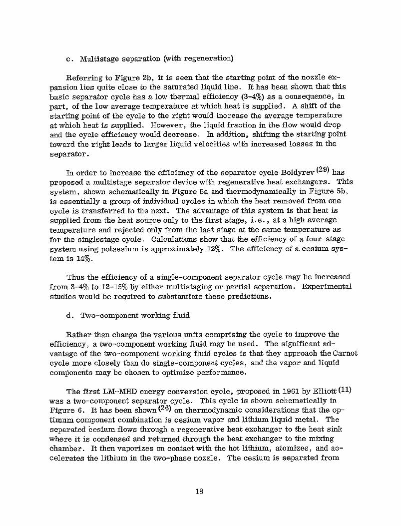
c. Multistage separation (with regeneration)
Referring to Figure 2b, it is seen that the starting point of the nozzle expansion lies quite close to the saturated liquid line. It has been shown that this basic separator cycle has a low thermal efficiency (3-4%) as a consequence, in part, of the low average temperature at which heat is supplied. A shift of the starting point of the cycle to the right would increase the average temperature at which heat is supplied. However, the liquid fraction in the flow would drop and the cycle efficiency would decrease. In addition, shifting the starting point toward the right leads to larger liquid velocities with increased losses in the separator.
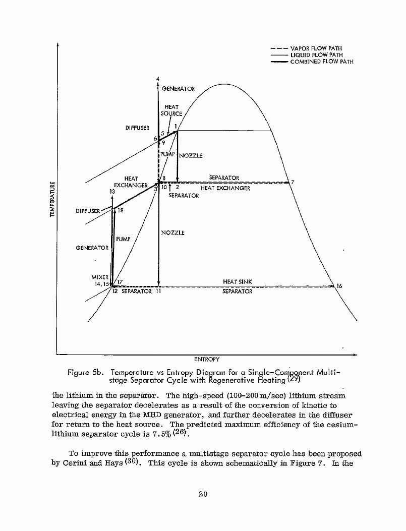
In order to increase the efficiency of the separator cycle Boldyrev (29) has proposed a multistage separator device with regenerative heat exchangers. This system, shown schematically in Figure 5a and thermodynamically in Figure 5b, is essentially a group of individual cycles in which the heat removed from one cycle is transferred to the next. The advantage of this system is that heat is supplied from the heat source only to the first stage, i.e., at a high average temperature and rejected only from the last stage at the same temperature as for the singlestage cycle. Calculations show that the efficiency of a four-stage system using potassium is approximately 12%. The efficiency of a cesium system is 14%.
Thus the efficiency of a single-component separator cycle may be increased from 3-4% to 12-15% by either multistaging or partial separation. Experimental studies would be required to substantiate these predictions.
d. Two-component working fluid
Rather than change the various units comprising the cycle to improve the efficiency, a two-component working fluid may be used. The significant advantage of the two-component working fluid cycles is that they approach the Carnot cycle more closely than do single-component cycles, and the vapor and liquid componeits may be chosen to optimize performance.
The first LM-MHD energy conversion cycle, ,proposed in 1961 by Elliott (11) was a two-component separator cycle. This cycle is shown schematically in Figure 6. It has been shown (26) on thermodynamic considerations that the optimum component combination is cesium vapor and lithium liquid metal. The separated esium flows through a regenerative heat exchanger to the heat sink where it is condensed and returned through the heat exchanger to the mixing chamber. It then vaporizes on contact with the hot lithium, atomizes, and accelerates the lithium in the two-phase nozzle. The cesium is separated from
18

15
Figure 5a. Single-Component Multistage Separator Cycle with Regenerative Heating (29)
14
- -- VAPOR FLOW PATH LIQUID FLOW PATH COMBINED FLOW PATH
4 GENERATOR
HEAT
PUMP NOZZLE
HEAT 8SEPARATOREXHAGR:AN R,3 lO HEAT EXCHAN GERD13 :
-/ SEPARATOR
NOZZLE PUMP
GENERATOR
MIXER
14, 15 17 HEAT SINK 12 SEPARATOR 11 SEPARATOR
ENTROPY
Figure 5b. Temperature vs Entropy Diagram for a Single-Co2R2p ent Multistage Separator Cycle with Regenerative Heating V)
the lithium in the separator. The high-speed (100-200 m/see) lithium stream leaving the separator decelerates as a-result of the conversion of kinetic to electrical energy in the MHD generator, and further decelerates in the diffuser for return to the heat source. The predicted maximum efficiency of the cesiumlithium separator cycle is 7.5%(26).
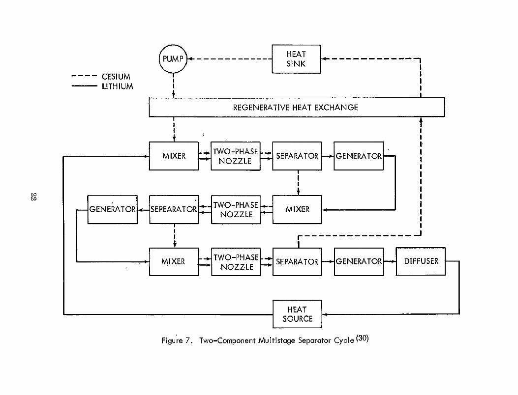
To improve this performance a multistage separator cycle has been proposed by Cerini and flays (30). This cycle is shown schematically in Figure 7. In the
20

10 HEAT 9 P -- SINK -4-1--- CI
/I CESIUM I LITHIUM
LID 12I- DIFFUSER
-I-7
MIERTWO-PHASE-4o SEPARATOR GENERATOR DFUE
I ___HEAT I SOURCE6
Figure 6. Two-Component Separator Cycle (11)
-5
CESIUM LITHIUM I
.H
PUMP----SINK
EAT
I
I
REGENERATIVE HEAT EXCHANGE
I I
LID
SEERI1KNO ZE1IEMIXER NOZZLE SEPARATOR
II
II 1
GENERATOR
I
GENERATOR SEEARTOR._ NOZZLE MIXER IIH
I I
GE~11 ARI'WOPHS
SOURCE
Figure 7. Two-Component Multistage Separator Cycle (30)
first stage of the multistage cycle shown, the cesium and lithium are mixed, expanded and then separated. The exiting lithium liquid passes through the generator and is then remixed with the cesium vapor from which it had been separated. The process continues in subsequent stages until the appropriate amount of kinetic energy has been removed from the lithium. Sufficient dynamic pressure is retained in the lithium to return it to the first stage via the heat source. The cesium separated in the final stage is returned to the heat sink through a regenerative heat exchanger. The cesium leaves the heat sink as a saturated liquid, is pumped through the regenerative heat exchanger to the first stage mixer.
An analysis of this system showed a maximum cycle efficiency of 10%, as compared to 7.5%for the single stage cycle.
Injector-Condenser
In the injector-condenser device thermal energy is converted to either flow energy (stagnation pressure) or kinetic energy.. The device is a form of the jet pump which operates with two-phase flows rather than a single-phase flow. A liquid vapor mixture and a subcooled liquid, after acceleration in separation nozzles, are combined in the injector-condenser mixing chamber resulting in the simultaneous condensation of the vapor and pumping of the combined liquid flow. The injector-condenser is designed to exit the flow with either a high kinetic energy or at pressures and temperatures which are higher than those existing at either inlet state.
Single- component
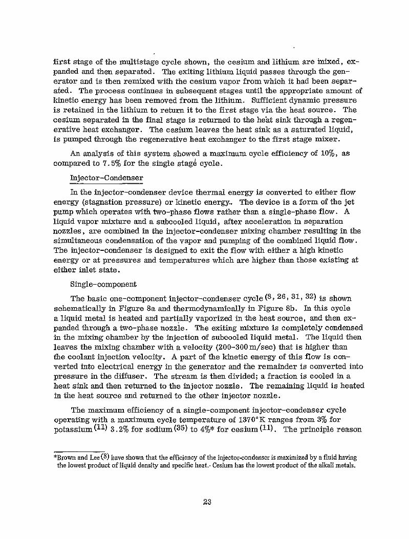
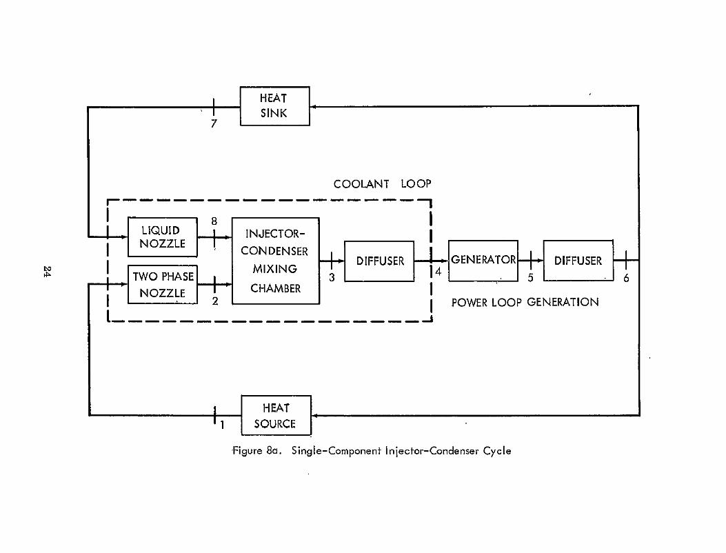
The basic one-component injector-condenser cycle (8, 26, 31, 32) is shown schematically in Figure 8a and thermodynamically in Figure 8b. In this cycle a liquid metal is heated and partially vaporized in the heat source, and then expanded through a two-phase nozzle. The exiting mixture is completely condensed in the mixing chamber by the injection of subcooled liquid metal. The liquid then leaves the mixing chamber with a velocity (200-300 m/sec) that is higher than the coolant injection velocity. A part of the kinetic energy of this flow is converted into electrical energy in the generator and the remainder is converted into pressure in the diffuser. The stream is then divided; a fraction is cooled in a heat sink and then returned to the injector nozzle. The remaining liquid is heated in the heat source and returned to the other injector nozzle.
The maximum efficiency of a single-component injector-condenser cycle operating with a maximum cycle temperature of 1370'K ranges from 3% for potassium (11) 3.2%for sodium (3 5 ) to 4%* for cesium (11). The principle reason
*Brown and Lee (8) have shown that the efficiency of the injector-condenser is maximized by a fluid having the lowest product of liquid density and specific heat.- Cesium has the lowest product of the alkali metals.
23
COOLANT LOOP
_ _ _ -_ - -_ __-- - - _ - - -
8LIQUID INJECTOR-NOZZLE]-- CONDENSER NCDIFFUSER 4GENERATOR DIFFUSER +
TWO PHASE 3 5 I NOZZLE I 2 CAME I
NO HAMBER POWER LOOP GENERATION
FigSOURieC
-Figure 8a. SinglIe- Component Injector-Condenser Cycle

---- LIQUID FLOW PATH -- TWO-PHASE FLOW PATH
- COMBINED FLOW PATH
4
HEAT SOURCE
DIFFUSER GENERATOR
HEAT
I TWO PHASE NOZZLE
5LIQUIDNOZZLEI
8 MIXING CHAMBER
ENTROPY
Figure 8b. Temperature vs Entropy Diagram for a Single-Component Injector-Condenser Cycle
for this low cycle efficiency is large shock losses in the injector condenser mixing chamber. It is possible to reduce these losses by injecting a liquid having the same velocity as the vapor, however this requires the cycle to Qperate very close to the saturated liquid line where the overall cycle efficiency would be low'. Another reason for the low efficiency is that the thermal energy content of the fluid leaving the generator is quite high. This energy is not utilized in this basic cycle.
25
Several modifications of the basic injector-condenser cycle have been proposed:
3 3 )a. Preheating( 2 5 ,
b. Regeneration (8)
c. Multistage inejection-condensation (10, 12, 29, 32, 34)
d. Two-component working fluid (26)
These modifications will be reviewed in the remainder of this section.
a. Preheating
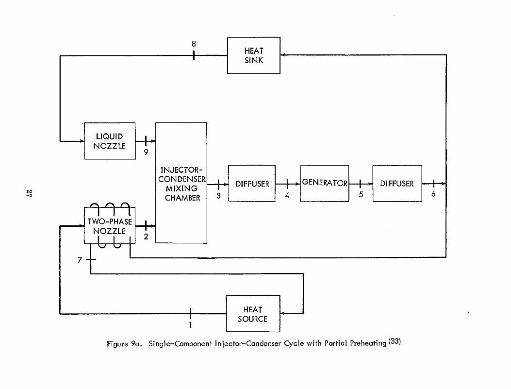
Radebold (25) first suggested the idea of preheating the liquid metal flowing back to the heat source by heat exchange with the vapor expanding in the nozzle. Rex (33) has analyzed the heat transfer across the nozzle wall and has computed the efficiency of single-component injector-condenser cycles with two different preheating modes.
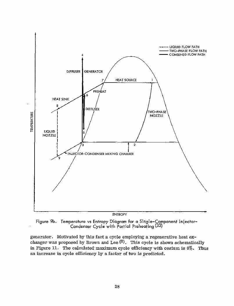
In the first mode, shown schematically in Figure 9a and thermodynamically in Figure 9b, the portion of the flow that returns to the heat source is first preheated by the two-phase nozzle. For potassium, a maximum cycle efficiency of 6.9% is predicted. This is to be compared to an efficiency of 3. 0%(26) for the same cycle conditions without preheating.
The improvement in cycle efficiency resulting from preheating may be further enhanced by dividing the flow downstream of the heat sink rather than after the diffuser. This mode is shown schematically in Figure 10a and thermodynamically in Figure l0b. After the entire flow is cooled a portion is used for injection and the remainder is preheated by the two-phase nozzle. The cycle efficiency for this mode has a maximum value of 10.2% for potassium. This is greater than three times the efficiency of the same cycle without preheating.
It must be pointed out that frictional losses resulting from the preheating process have not been included in the calculation of these maximum cycle efficiencies. It is estimated (33), however, that these friction losses will, reduce the efficiencies to approximately 6-8%.
b. Regeneration
As previously mentioned one of the reasons for the low efficiency of the basic injector-condenser cycle is the high temperature of the fluid leaving the
26
7
SLIQUID
~NOZZLE
INJECTOR-CONDENSER DIFFUSER GENERATOR DIFFUSER
MIX[NGCHAMBER 3456
TWO-PHASE
NOZZLE I 1 1I 2
HEAT SOURCE
I
Figure 9a. Single-Component Injector-Condenser Cycle with Partial Preheating (33)
4
---- LIQUID FLOW PATH - TWO-PHASE FLOW PATH - COMBINEDFLOW PATH
DIFFUSER GENERATOR
7 HEAT SOURCE I
PREHEAT
HEAT SINK 6
DNUSER NOZZLE
LIQUID
NOZZLE
ENTROPY
Figure 9b. Temperature vs Entropy Diagram for a Single-Component Injector-Condenser Cycle with Partial Preheating (33)
generator. Motivated by this fact a cycle employing a regenerative heat exchanger was proposed by Brown and Lee (8). This cycle is shown schematically in Figure ll. The calculated maximum cycle efficiency with cesium is 8%. Thus an increase in cycle efficiency by a factor of two is predicted.
28

_ LIQUID _
NOZZLE
---ICONDENSER +,DIFFUSER GENERATOR DIFFUSER bo MIXING
SCHAMBER 3456
. TWO-PHASE
HEAT I SSOURCE
Figure 10a. Single-Comnponent In ector-Con denser Cycle with Preheating (33)

LIQUID FLOW PATH - TWO-PHASE FLOW PATH
4 - COMBINED FLOW PATH
DIFFUSER GENERATOR
116 9 HEAT SOURCE I
PREHEAT
HEAT SINK DIFFUSER TWO-PHASE
NOZZLE
LIQUID
NOZZLE
3 INJECTOR-CONDENSER 2
ENTROPY
Figure 10b. Temperature vs Entropy Diagram for a Sin le-Component Injector-Condenser Cycle with Preheating (33)
c. Multistaging
In systems of this type, an attempt is made-to reduce the mixing losses present in the injector-condenser mixing chamber by using a step-wise injection, in each stage of which, the velocity differences, between the sub-cooled liquid and the mixture are small. Three multistage injection cycles have been investigated.
30

LIQUID NOZZLE INJECTOR-_
CONDENSER DIFFUSER GENERATOR MIXING
TWO-PHASE CHAMBER
NOZZLE
REGENERATOR
SOURCE
Figure 11. Single-Component Injector-Condenser Cycle wit'h Regeneration (8)

The first such cycle was proposed by Radebold (10) and Prem (12) and an
alyzed by Oldekop and Rex (31). Figure 12a shows the flow diagram and Figure 12b shows the temperature-entropy diagram of this multistage process. A
-portion of the flow is heated and partially evaporated in the heat source. It then enters a series of nozzles and injector-condenser mixing chambers where it is successively expanded and condensed. Calculations performed on this system (31) indicate that even by optimizing the process, the advantage over the single stage injector condenser is rather low. For example, the efficiency of an optimized multistage injector condenser cycle is only 25-50% greater than that of the single stage system using sodium or potassium respectively. This small improvement is likely to be negated by increased frictional losses in the multistage system. The poor performance of this multistage cycle is due to the irreversible mixing of streams at different temperatures (29), see Figure 12b.
A second multistage injection mode has therefore been proposed by Boldyrev (29), in which losses due to the irreversible mixing of streams at different temperatures, as well as shock losses, are eliminated. This cycle is shown schematically in Figure 13a and thermodynamically in Figure 13b. In this system complete condensation occurs in-each stage and each stage operates from the saturated liquid line. The maximum efficiency of this multistage injectorcondenser cycle, for potassium with 4 stages, is 14%. This is to be compared to a maximum efficiency of 4% for the single stage cycle and 4.5% for the other multistage cycle.
A third mode of multistage injector-condensers has been investigated by Boldyrev (29) and Rex (34). In this mode, regeneration is added, resulting in a further increase in the maximum cycle efficiency. However the friction losses turn out to be so large that the cycle appears to be impracticable (34). This may also be true of Boldyrev's multistage cycle (Figures 13a and 13b).
d. Two-components
The requirements of the injector-condenser on the thermal capacity of the working fluid can not be adequately satisfied by one component. The specific heat should be high in order to minimize shock losses incurred during mixing and it should be low to obtain a high thermal efficiency. This situation has led to the development of the two-component injector-condenser system. In this system different substances are used in the heat source and heat sink loops. By using a high heat capacity substance in the heat sink loop the amount of this coolant required is less. Kinetic energy losses in the injector-condenser are thereby reduced resulting in an increase in the cycle efficiency. It has been shown (26) that cesium and lithium are the optimum components, the high specific heat lithium being the sub-cooled component. Some researchers propose using potassium-lithium systems however the high solubility of potassium in lithium (26)
results in a low performance of such a cycle.
32
. LIQUID LIQUID OcLIQUID
NOZZLE A INJECTO NOZL B INJECTIR NOZEC INJECTOR
CON E-SER CONDE4SER CONDENSERL S CHAMBER - CHAMBER CRAMBE -
DIFFUSER GNRTRDFUNIHIASESE EBpMSEIE I. ] N ID F U E 1, IAO
MULTI-STAGE INnECTOR-CONDENSeR
Figure 12a. Sing Ie-Component Injector-Condenser Cycle with Multistage Injection (31)

- -- LIQUID FLOW PATH - TWO-PHASE FLOW PATH
-COMBINED FLOW PATH
4
DIFFUSER GENERATOR HEAT SOURCE .
LIQUID NOZZLE AXN. 2 NOZZLE A
/ / TWO-PHASE
HEAT SINK 6
7: 26x7
I MIXING CHAMBER A,
I TWO-PHASE U2d 8a NlOZZLE 8
LIQUID NOZZLE B
LIQUID I1 ' 2
~CHAMBER B " TWO:PHASE
NOZZLE C
2 ,L_<5 1NECTOR-CON DENSER
MIXING CHAMBER C
ENTROPY
Figure 12b. Temperature Entropy Diagram for a Single-Component Injector-Condenser Cycle with Multistage Injection (31)
Two variations of a single-stage two-component injector-condenser cycle have been proposed. (26) They vary only in the location of the separator; in one the two components are separated after passing through the MHD generator, in the other, before entering the generator. Since the latter is the more efficient system only it will be illustrated. The flow path is shown in Figure 14.
In this cycle, a low-quality mixture of a liquid metal and its own vapor is expanded through a two-phase nozzle. The exiting mixture is condensed in the
34

-6
_ LIQUID
NOZZLE + INJECTOR CONDENSER 3c 5-6c
MIXING GENERATOR 5c GENERATOR Ccle wi MulctFgr 2a CHAMBERPHASE + C DFUE ENOZZLEc
INJECTOR 'I NOZZLE
6b56 3 CONDENSER B
MIXINGInjGENERATORGENERATOR BBDIFFUSER B B PHASE
+NOZZLEB
7aSLIQUID
NOZZLE + INJECTOR
A CONDENSER 3al I4 -
GENE RATOR 5@i GENERAT OR 6aMIXING
T meA' i su -c ol se cond cnTWO 2a CHAMBER PHA SE A DIFUE
I [HEAT
Figure 13a. Sing le-Component Injector-Condenser Cycle with Multistage Injection and Generation (29)
injector by the injection of a sub-cooled second component. The mixture exiting
the injector-condenser, now in the liquid state, has a velocity which is higher than the sub-cooled liquid injection velocity. The two liquids are separated and .the coolant is returned to the injector-condenser via the heat sink. The other component decelerates through the production of electrical power in the generator and then returns to the injector via a diffuser and a heat source, where it is partially vaporized. The maximum efficiency of a cesium-lithium cycle of this kind is 6.8%. (26)
35

- TWO-PHASE FLOW PATH ----- LIQUID FLOW PATH
-COMBINED FLOW PATH
4a
n/ L5a
4b
4c2
ENTROPY
Figure 13b. Temperature vs nropy Diagram for a Single-Component Injector-
Condenser Cycle with Multistage Injection and Generation (29)
36
I

--- VAPOR LIQUID OR MIXTURE
..... SINK
LIQUIDNOZZLE
TWO PHASENOZZLE
F INJECTOR-
CONDENSER SEPARATOR
GENERATOR
_
IFF-
DIFFUSER
F--
FiSOURCE
Figure 14. Two-Component Injector-Condenser Cycle (26)

Boldyrev (29) has modified this basic two-component injector-condenser cycle by devising a highly efficient separation scheme. Boldyrev's cycle is shown in Figure 15. This cycle differs from the basic two-component cycle in several ways. The components are not separated until after passing through the generator and the heat source. The cesium is completely vaporized while the lithium remains liquid. Both of the separated substances then are regeneratively cooled. The cesium vapor is partially condensed in the heat exchanger and sent to the two-phase flow nozzle. The lithium liquid passes through the regenerative heat exchanger, is combined in the heat sink and pumped into the liquid nozzle. The predicted efficiency for this modified cycle is approximately 19%, a significant increase above the 6.8%for the basic two-component system.
Two-Phase Flow
There are two different basic cycles that pass a two-phase flow directly through the generator section. The emulsion flow cycle employs a homogeneous vapor-liquid mixture whereas the slug flow cycle employs an inhomogeneous mixture. The principle objective of both two-phase flow cycles is to attempt to minimize the frictional and thermal to kinetic energy transfer losses inherent in the previously discussed fog-flow cycles. The secondary objective is the reduction of electrical end losses that occur when the liquid metal enters and leaves the magnetic field. The degree to which these objectives have been achieved with the emulsion and slug flow cycles is considered in the following sections.
Emulsion Flow
In this type of a system the working fluid is an emulsion consisting of a gas dispersed as bubbles in a liquid metal. The emulsion is not subjected to separation before entering the generator but passes directly through the MHD channel. If the emulsion is sufficiently fine and homogeneous, the energy transfer between the non-conducting, but elastic gas and the non-elastic, bat conducting liquid metal becomes considerably more efficient and the thermodynamic efficiency increases accordingly.
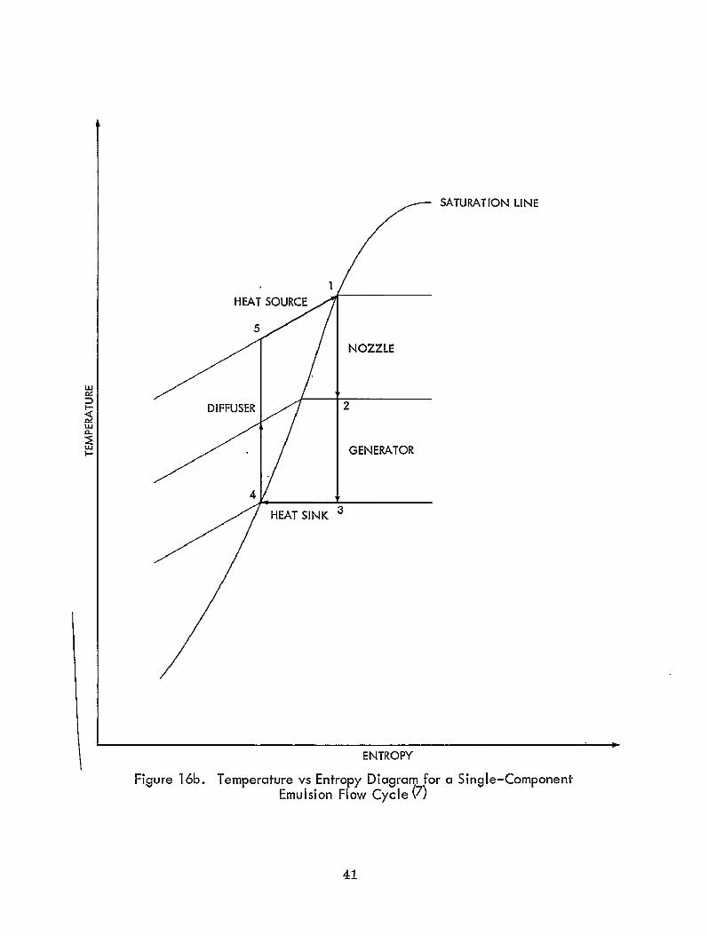
The basic one-component emulsion flow cycle, first proposed by Petrick (7) is shown schematically in Figure 16a and thermodynamically in Figure 16b. The working fluid receives thermal energy in the heat source and then enters the two-phase nozzle either as a vapor or a liquid vapor mixture. As the flow accelerates through the nozzle a portion of the thermal energy of the fluid is converted into kinetic energy. The two-phase mixture then passes through the MHID generator where the kinetic energy of the fluid is converted into electrical energy. The excess energy is removed in a heat sink and the fluid is returned to the heat source via a diffuser. The typical value of the theoretical maximum efficiency of this cycle is 6%for cesium(7) and 14% for potassium(35). Subsequent analysis by Petrick (16) seems to indicate that the quoted efficiency of 14% is in error, the correct value being closer to 6%.
38

NOZZLE INJECTOR
w° ---CONDENSER1R MIXINGDIFFUSER GENERTOR DIFFUSER
TWO-PHASE/'NOZZLE
CHAMBER
REGENERATIVE
HEAT EXCHANGE
CESIUM VAPORF REGENERATIVE
EATHEATH EXCHANGE+HREA
rITHIUM LIQUID Figure 15. Two-Component Injector-Condenser Cycle with Regeneration (29)

2
GENERATOR
DIFFUSER
TWO-PHASE -5 NOZZLE
SOURCE
Figure 16a. Single-Component Emulsion Flow Cycle (7)
A NaK LM-MHD system based on this basic cycle has been investigated experimentafly by Petrick (16). It was observed that there exists a limiting quality ( < 0.02) and void fraction (< 0.85) range where it is feasible to pass the twophase mixture directly through the generator without its performance dropping off radically. The drop in performance is due to the change in the flow pattern from an emulsion flow to a fog flow with the accompanying decrease in electrical conductivity. The data therefore tends to indicate a major limitation on the performance of a one-component emulsion flow cycle and efficiencies above 6%
40
SATURATION LINE
HEAT SORC
NOZZLE
DIFFUSER2
114
SINK AHEAT
ENTROPY
Figure 16b. Temperature vs Entropy Diagram for a Single-Component Emulsion Flow Cycle (7)
41

therefore seem doubtful. It is interesting to note that if the generator behaves isentropically and if it could operate with very high quality, the Petrick cycle. can, in the limit, approach the Carnot cycle. However the quality is restricted to very low values and the cycle efficiency falls well below the Carnot efficiency.
In order to overcome this limitation two approaches have been taken:
a. Simultaneous generation and separation (36)
b. Two-component emulsion (22)
a. Simultaneous generation and separation
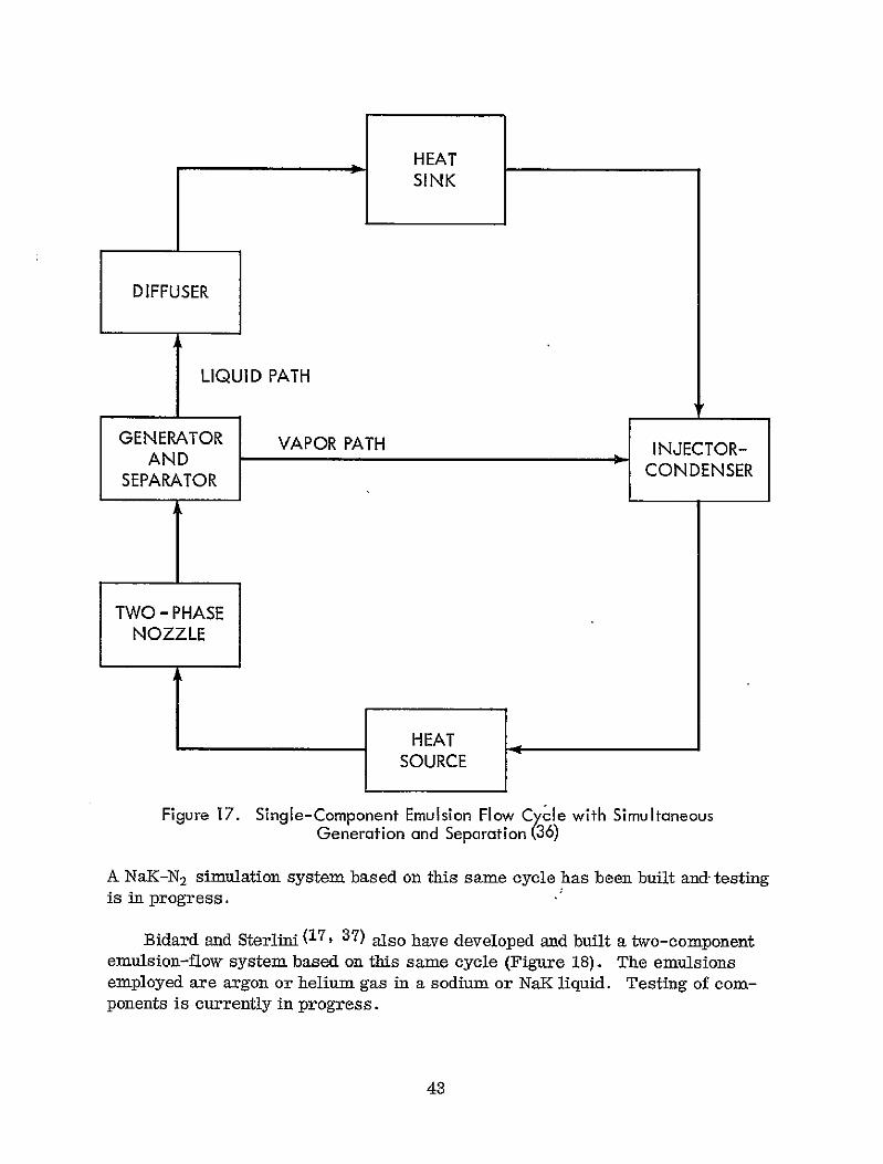
The single-component emulsion-flow system proposed by Holmgren and Johnson (36) is shown schematically in Figure 17. This system exhibits two major differences with the basic emulsion flow cycle, Figure 16a. In this system the separation takes place within the generator simultaneously with power generation. In this way the undesirable transition from an emulsion to a fog flow is prevented. The generator is designed with a circular fluid flow path so that centrifugally forced impingement on a surface causes phase separation. Since phase separation occurs within the generator the velocity loss that was incurred in the basic cycle when separating out the vapor phase upstream of the generator is reduced. A further advantage of this spiral flow configuration is that end losses are eliminated.
The vapor leaving the generator goes to an injector-condenser. The liquid, after converting some remaining kinetic energy into pressure in a diffuser, and rejecting the excess energy in a heat sink, also goes to the injector-condenser. The injector-condenser acts as a pressure generating device in which the latent heat of vaporization is recovered as pressure. The fluid, in either all liquid or in a two-phase condition, enters the heat source and completes the cycle. The recovery of the heat of vaporization by the condenser injector increases the efficiency of this cycle as compared with the basic cycle (Figure 16a), because the thermal energy required to produce the same heat source exit conditions is reduced. The efficiency of this modified cycle is 20%. Additional effort is now required to obtain experimental verification of this performance.
b. Two-component emulsion
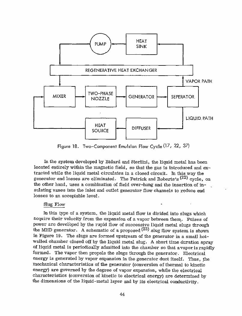
A recent analysis by Petrick and Roberts (22) of a two-component emulsion flow cycle -has indicated very favorable performance. This cycle is shown schematically in Figure 18. The calculated efficiency of a lithium-cesium system based on this cycle is 11.5%, with account taken of all loss mechanisms.
42
HEAT SINK
DIFFUSER
I LIQUID PATH
GENERATOR VAPOR PATH INJECTOR-AND CONDENSER
SEPARATOR
TWO - PHASE NOZZLE
J HEAT
SOURCE
Figure 17. Single-Component Emulsion Flow Cycle with Simultaneous Generation and Separation (36)
A NaK-N 2 simulation system based on this sane cycle has been built and, testing is in progress.
Bidard and Sterlini (17, 37) also have developed and built a two-component emulsion-flow system based on this same cycle (Figure 18). The emulsions employed are argon or helium gas in a sodium or NaR liquid. Testing of components is currently in progress.
43
REGENERATIVE HEAT EXCHANGER
VAPOR PATH
TWO-PHASE GENERATOR SEPERATOR,
NOZZLEIX R
LIQUID. ATHHEAT
SOURCE DIFFUSER
Figure 18. Two-Component Emulsion Flow Cycle (17, 22, 37)
In the system developed by Bidard and Sterlini, the liquid metal has been located entirely within the magnetic field, so that the gas is introduced and extracted while the liquid metal circulates in a closed circuit. In this way the generator end losses are eliminated. The Petrick and Roberts's (22) cycle, on the other hand, uses a combination of field over-hang and the insertion of insulating vanes into the inlet and outlet generator flow channels to reduce end losses to an acceptable level.
Slug Flow
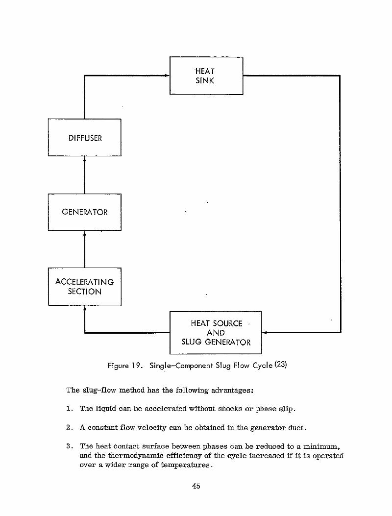
In this type of a system, the liquid metal flow is divided into slugs which acquire their velocity from the expansion of a vapor between them. Pulses of power are develbped by the rapid flow of successive liquid metal slugs through the MHD generator. A schematic of a proposed (23) slug flow system is shown in Figure 19. The slugs are formed upstream of the generator in a small hotwalled chamber closed off by the liquid metal slug. A short time duration spray of liquid metal is periodically admitted into the chamber so that avapor is rapidly formed. The vapor then propels the slugs through the generator. Electrical energy is generated by vapor expansion in the generator duct itself. Thus, the mechanical characteristics of the generator (conversion of thermal to kinetic energy) are governed by the degree of vapor expansion, while the electrical characteristics (conversion of kinetic to electrical energy) are determined by the dimensions of the liquid-metal layer and by its electrical conductivity.
44
DIFFUSER
__~I_ GENERATOR
__~I_ ACCELERATING
SECTION
HEAT SOURCE AND
SLUG GENERATOR
Figure 19. Single-Component Slug Flow Cycle (23)
The slug-flow method has the following advantages:
1. The liquid can be accelerated without shocks or phase slip.
2. A constant flow velocity can be obtained in the generator duct.
3. The heat contact surface between phases can be reduced to a minimum, and the thermodynamic efficiency of the cycle increased if it is operated over a wider range of temperatures.
45

4. Electrical power can be obtained using a synchronous generator.
5. The efficiency is insensitive to power level thereby permitting scaling down to low power output.
The slug flow acceleration technique in conjunction with the synchronous generation principle, allows the construction of both very high and very low output power level systems. Efficiences' ranging from 15% for this particular system to 30% for a system under study in Russia (38) have been predicted. Because of its relatively high efficiency and ability to operate at very low output power levels it is very well suited to current space applications, although experimental work remains to be initiated.
SUMMARY
The maximum predicted efficiencies for the four basic LM-MHD cycles and all modifications included in this review are shown in Table 3. The maximum cycle temperature ranged from 11200 to 1500°K, with a mean value -of 1370°E; the minimum cycle temperature ranged from 7000 to 1090 0K, with a mean value of 920'K; and the generator was assumed to have an efficiency of 70%. The following observations and comments are made:
1. For all cycles two-component mixtures yield higher efficiencies than single-component fluids by approximately a factor of two. The only exception is the high value reported (35) for a potassium emulsion cycle (14%). Since it was difficult to evaluate the conditions under which this value was obtained, this efficiency should be regarded as perhaps a somewhat optimistic estimate.
2. The most efficient one-component material, regardless of cycle, is cesium. Although the table indicates that for some cycles, potassiumlithium is a more efficient two-component material than cesiumlithium, the greater soluability of potassium in lithium may render that combination less useful than cesium-lithium.
3. The maximum efficiencies of the two different basic fog flow cycles are essentially equal; 3-4%for one component, 6-8% for two-component cycles.
4. The predicted efficiencies of both the separator and injector-condenser cycles exhibited significant increases upon modification. Efficiencies in the-10-20% range.are typical for these modified cyles.. However the added complexity and potentially increased frictional losses must be considered.
46

Table 3 Predicted Maximum Efficiency for Liquid-Metal MHD Cycles
CYCLE NUMBER OF SPCE MAXIMUM EFFICIENCY CYCLES
CLASSIFICATION COMPONENTS BASIC CYCLE MODIFIEDCYCLE
MULTI -STAGE PREIHEATING REGENERATION MULTI-STAGE MULTI-STAGE WITH REGENERATION
1 POTASSIUM 8,2, 31, 32)
3.0 (25, 33)6.9-10.2
(8) -
(10, 12, 31)4.5
(29)14 0
(29 34)
INJECTOR- SODIUM 3.2 - - 3.8 -CONDENSER CESIUM 4.0 8.0 - -
(26) (29) 2 CESIUM-LITHIUM 6.8 19.0
POTASSIUM-LITHIUM 7.5 -
DOWNSTREAM PARTIAL MULTI-STAGE MULTI-STAGE I (26) MIXING(27) SEPARATION
(28) WITH REGENERATION
(29)
SEPARATOR POTASSIUM 3.0 - 15.5 12.0 CESIUM 4,0 - - 14.0
2 CESIUM-LITHIUM (11)7.5 (30)10,0
S IMULTANEOUS GENERATION AND
SEPARATION
EMULSION CESIUM NaK
(7, 16, 35)6.06.0
36)20.0 -
POTASSIUM 14.0 (17, 22, 37)
2 ARGON-SODIUM -
CESI UM-LITHIUM 11.5
(23)
SLUG CESIUM 14.6 (38)
CARBON DIOXIDE2 TIN ALLOY 21.5
POTASSIUM LITHIUM 30.0

5. The most developed cycles are the injector-condenser and separator cycles. However, both of these fog flow cycles tend to have lower efficiencies than the two-phase cycles. This is due to the larger losses in the separator and injector units. For this reason it would appear that modifications of the emulsion and slug flow cycles should be investigated.
6. The highest predicted cycle efficiency, 30%, is for a basic twocomponent slug flow system using potassium and lithium.
REFERENCES
1. Proceedings First International Symposium on MHD Electrical Power Generation, Newcastle-Upon-Tyne, 1962, IEE, London (1963)
2. Proceedings Second International Symposium on MIE) Electrical Power Generation, Paris, Vol. 2, 1964, OECD/ENEA, Paris (1964)
3. Proceedings Third International Symposium on MHD Electrical Power Generation, Salzburg, Vol. 3, 1966, IAEA, Vienna, (1966)
4. Proceedings Fourth International Symposium on MHD Electrical Power Generation, Warsaw, 1968, Vol. 6, [AEA, Vienna (1969)
5. Jackson, W. D. and E. S. Pierson, "Operating Characteristics of the MHD Induction Generator," in Reference 1
6. Jackson, W. D., E. S. Pierson and R. P. Porter, "Design Considerations for MHD Induction Generators," Paper No. 61 inReference 2
7. Petrick, M. and K. Lee, "Performance Characteristics of a Liquid Metal MHD Generator," Paper No. 62 in Reference 2
8. Brown, G. A. and K. S. fLee, "A Liquid-Metal MHD Power Generation Cycle Using a Condensing Ejector," Paper No. 60 in Reference, 2
9: Prem, L. L. and W. E. Parkins, "A New Method of MHD Power Conversion Employing a Fluid Metal," Paper No. 63 in Reference 2
10. Radebold, R. D., H. Lang, W. Westphal and W. Lochte-Holtgreven, "Energy Conversion with Liquid Metal Working Fluids in MHD Staustrahlrohr" Paper No. 64 in Reference 2
48
11. Elliott, D. G., "A Two-Fluid Magnetohydrodynamic Cycle for Nuclear Power Conversion," ARS J. 32, 924-928, (1962)
12. Prem, L. L., "Analytical and Experimental Results of the Fluid Metal MHD Power Conversion Program,' t Paper SM-74/184 in Reference 3
13. Radebold, R., H. Lang, T. Schulz, H. Wel, E. Mlein and K. H. Wagner,"Energy Conversion With Liquid Metals Working Fluids in MHD-Staustrahlrohr," Paper SM-74/30 in Reference 3
14. Elliott, D. G., D. J. Cerini, L. G. Hays and E. Weinberg, "Theoretical and Experimental Investigation of Liquid Metal 1VIHD Power Generation," Paper SM-74/177 in Reference 3
15. Kirillov, P. L., V. I. Subbatin, I. P. Stakhanov and N. M. Turchin, "Measuring the Electrical Condudtivity of a Liquid-Vapor Potassium Mixture," Paper SM-74/106 in Reference 3
16. Petrick, M., "MHD Generators Operating with Two-Phase Liquid Metal Flows," Paper SM-74/196 in Reference 3
17. Bidard, R. and J. Sterlini, "MHD Generator Using An Emulsion," Paper SM-74/108, in Reference 3
18. MIHD For Central Station Power Generation: A Plan For Action, Panel on Magnetohydrodynamics (MHD), Office of Science and Technology, June 1969
19. MHD Electrical Power Generation - The 1969 Status Report, Joint ENEA/ IAEA International Liaison Group on MHD Electrical Power Generation, April 1969
20. Elliott, D. G., "Performance Capabilities of Liquid-Metal MED Induction Generators," Paper No. SM-107/41 in Reference 4
21. Dmitriyev, K. I., E. A. Zotova, I. A.. Ivanov, U. S. Presnyakov and F. 1R. Ulinich, "Investigation of a Liquid-Metal Jet M-D Generator," Paper No. SM-107/134, in Reference 4
22. Petrick, M. and J. Roberts , "Analytical and Experimental Studies of Liquid-Metal Faraday Generators," Paper SM-107/20, in Reference 4
23. Bjerklie, J. W. and J. R. Powell, "A Liquid-Metal MHD Power Generation Scheme Using Intermittent Vaporization," Paper SM-107/212, in Reference 4
49

24. Boldyrev, V. M., et al, "Thermodynamic Analysis of New Cycles For Liquid-Metal MHD Generators," Paper SM-107/142 of Reference 4
25. Radebold, R., "Energy Conversion with Liquid-Metal Working Fluids in the M£D-Staustrahlrohr," Paper No. SM-1Q7/5 in Reference 4
26. Weinberg, E. and L. G. Hays, "Compassion of Liquid-Metal Magnetohydrodynamic Power Conversion Cycles," Tech. Rept. No. 32-946, Jet Propulsion Laboratory, Pasadena, California, Aug. 1966
27. Aladjev, I. T., et al, "Studies of Liquid-Metal MHD Cycles at the Krzhizhanovsky Power Institute," Tenth Symposium on Engineering Aspects of Magnetohydrodynamics, MIT, Cambridge, Mass., 26-28, March, 1969
28. Proposal to Develop a Liquid Metal MHD Power System Based on the Kaye Cycle, Joseph Kaye & Co., Cambridge, Mass., November 22, 1965
29. Boldyrev, V. M., et al, "Thermodynamic Analysis of New Cycles for Liquid Metal MED Generators," Paper Sm-107/142 of Reference 4
30. Cerini, D. J. and L. G. Hays, "A Progress Report on the JPL Liquid-Metal Cycle," Tenth Symposium on Engineering Aspects of Magnetohydrodynamics, MIT, Cambridge, Mass., 26-28, March, 1969
31. Oldekop, W. and D. Rex, "The Efficiency of Liquid Metal MED Cycles with Multistage Injection," Eighth Symposium on Engineering Aspects of Magnetohydrodynamics, Stanford, California, 28-30, March, 1967
32. Jackson, W. D. and G. A. Brown, "Liquid Metal Magnetohydrodynamic Power Generator Utilizing the Condensing Ejector," Patent Disclosure, MIT, Cambridge, Mass., Oct. 15, 1962
33. Rex, D., "Liquid Metal MHD Cycles with Nozzle Preheating and Counterflow Condensation," Tenth Symposium on Engineering Aspects of Magnetohydrodynamics, Cambridge, Mass., 26-28, March, 1969
34. Rex, D., "The Mechanism of Different Types of Loss in Liquid-Metal MHD Cycles with Multistage Injection," Paper No. SM-107/111 in Reference 4
35. Petrick, M., Note in Rapporteur Section, p. 1871 of Reference 2
50

36. Holmgren, J. S. and K. P. Johnson, "A New Approach to Liquid Metal Power Generation," McDonnell Douglas Astronautics Company, Report No. DAC-58431, October 1966
37. Bidard, R. and J. Sterlini, "Study of Two-Phase Media for Use in MIHD Devices," Paper SM-107/75 in Reference 4
38. Bazeyev, Y. T., et al, "Laminar Flow Liquid-Metal MIHD Systems and Their Performance in Synchronous Generation Operation," Paper SM107/179 in Reference 4
51