Embed Size (px)
Citation preview

SUPPLIER:THIS MANUAL MUST BE GIVEN TO THERIDER OF THIS WHEELCHAIR.
RIDER:BEFORE USING THIS WHEELCHAIRREAD THIS ENTIRE MANUAL AND SAVEFOR FUTURE REFERENCE.
User
Instruction
Manual &
Warranty
Quickie P200
3 930336 Rev. E
SUNRISE LISTENSThank you for choosing a Quickie wheelchair.We want to hear your questions or comments about this manual, the safety and reliability of your chair, and theservice you receive from your Sunrise supplier. Please feel free to write or call us at the address and telephone number below:
SUNRISE HOME HEALTHCARE GROUPMOBILITY PRODUCTS DIVISIONCustomer Service Department7477 East Dry Creek ParkwayLongmont, Colorado 80503(303) 218-4500 or (800) 333-4000
Be sure to return your warranty card, and let us know if you change youraddress.This will allow us to keep you up to date with information about safety,new products and options to increase your use and enjoyment of this wheel-chair. If you lose your warranty card, call or write and we will gladly send you anew one.
FOR ANSWERS TO YOUR QUESTIONSYour authorized supplier knows your wheelchair best, and can answer most ofyour questions about chair safety, use and maintenance. For future reference, fill in the following:
Supplier:______________________________________________________________________________
Address: ______________________________________________________________________________
______________________________________________________________________________________
Telephone: ____________________________________________________________________________
Serial #:______________________________________ Date/Purchased: ________________________
1 . I N T R O D U C T I O N

5 930336 Rev. E
1 1 . T A B L E O F C O N T E N T S
VII. WARNINGS: COMPONENTS & OPTIONS ........................ 23A. Anti-Tip Levers.................................................................................... 23B. Armrests .............................................................................................. 23C. Batterie.................................................................................................. 23D. Cushion & Sling Seats ........................................................................ 23E. Fasteners .............................................................................................. 24F. Footrests .............................................................................................. 24G. Motor Lock .......................................................................................... 24H. On/Off Switch...................................................................................... 24I. Pneumatic Tires .................................................................................. 25J. Positioning Belts (Optional) ............................................................ 25K. Push Handles........................................................................................ 25L. Rear Wheel Locks (Optional).......................................................... 26M. Seating Systems .................................................................................. 26N. Upholstery Fabric .............................................................................. 26
VIII. TIPS FOR ATTENDANTS .............................................................. 27A. To Climb a Curb or Single Step ...................................................... 27B. To Descend a Curb or Single Step ................................................ 27
IX. SET UP,ADJUSTMENT & USE .................................................... 28Notes .......................................................................................................... 28Tools You Will Need ................................................................................ 29Check Out.................................................................................................. 29A. Power Drive Unit................................................................................ 30B. Battery Removal.................................................................................. 30C. Folding Backrest .................................................................................. 31D. Footrests .............................................................................................. 31E. Elevating Legrests (Optional) .......................................................... 32F. Remote Joystick Installation (Optional) ........................................ 32G. To Adjust the Height of the Remote Joystick (Optional).......... 32H. Remote Joystick Swing-Away Retractable Mount (Optional) .... 33I. Dual-Post Height-Adjustable Armrests.......................................... 33J. Height-Adjustable Armrests (Optional) ........................................ 33K. Seat Depth............................................................................................ 34L. 10" Drive Wheel ................................................................................ 35M. Dynamic Stabilizer .............................................................................. 36N. Seat Sling .............................................................................................. 37
4930336 Rev. E
1 1 . T A B L E O F C O N T E N T S
1. INTRODUCTION .............................................................................. 311. TABLE OF CONTENTS ..................................................................4 - 6
111. YOUR CHAIR AND ITS PARTS ..................................................7 - 8IV. NOTICE - READ BEFORE USE .................................................. 9V. EMI (ELECTROMAGNETIC INTERFERENCE) .................. 10
A. What is EMI ........................................................................................ 10B. What Effect Can EMI Have .............................................................. 10C. Sources of EMI .................................................................................... 11D. Distance From the Source................................................................ 11E. Immunity Level .................................................................................... 11F. Report All Suspected EMI Incidents .............................................. 12
VI. GENERAL WARNINGS.................................................................... 13A. Notice to Rider .................................................................................. 13B. Notice to Attendants ........................................................................ 13C. Weight Limit ........................................................................................ 14D. Controller Settings ............................................................................ 14E. EMI.......................................................................................................... 14F. Safety Checklist .................................................................................. 14G. Changes & Adjustments .................................................................... 14H. When Seated in a Parked Wheelchair .......................................... 15I. Environmental Conditions ................................................................ 15J. Terrain .................................................................................................. 16K. Street Use ............................................................................................ 16L. Motor Vehicle Safety .......................................................................... 16M. Center of Balance .............................................................................. 16N. Transfers................................................................................................ 17O. Reaching or Leaning .......................................................................... 18P. Dressing or Changing Clothes ........................................................ 18Q. Obstacles .............................................................................................. 19R. Driving in Reverse .............................................................................. 19S. Ramps, Slopes & Sidehills .................................................................. 19T. To Reduce the Risk of Falls,Tip-over or Loss of Control ........ 20U. Ramps at Home & Work .................................................................. 21V. Wheelchair Lifts .................................................................................. 21W. Curbs & Single Steps.......................................................................... 22X. Stairs ...................................................................................................... 22Y. Escalators .............................................................................................. 22
7 930336 Rev. E
1 1 1 . Y O U R C H A I R A N D I T S P A R T S
Q U I C K I E P 2 0 0
1
2
3
4
5
6
7
8
9
10
12
13
14
15
16
17
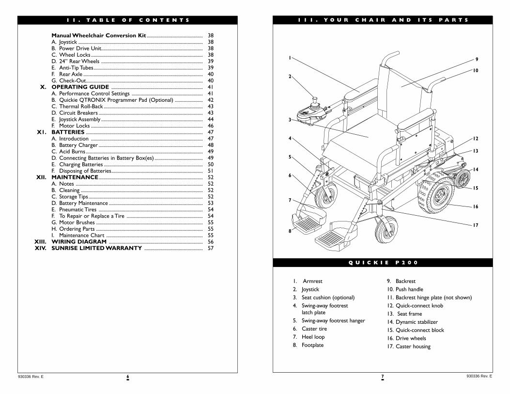
1. Armrest2. Joystick3. Seat cushion (optional)4. Swing-away footrest
latch plate5. Swing-away footrest hanger6. Caster tire7. Heel loop8. Footplate
9. Backrest10. Push handle11. Backrest hinge plate (not shown)12. Quick-connect knob13. Seat frame14. Dynamic stabilizer15. Quick-connect block16. Drive wheels17. Caster housing
6930336 Rev. E
1 1 . T A B L E O F C O N T E N T S
Manual Wheelchair Conversion Kit ............................................ 38A. Joystick .................................................................................................. 38B. Power Drive Unit................................................................................ 38C. Wheel Locks ........................................................................................ 38D. 24” Rear Wheels ................................................................................ 39E. Anti-Tip Tubes...................................................................................... 39F. Rear Axle .............................................................................................. 40G. Check-Out............................................................................................ 40
X. OPERATING GUIDE ........................................................................ 41A. Performance Control Settings ........................................................ 41B. Quickie QTRONIX Programmer Pad (Optional) ...................... 42C. Thermal Roll-Back .............................................................................. 43D. Circuit Breakers .................................................................................. 43E. Joystick Assembly ................................................................................ 44F. Motor Locks ........................................................................................ 46
X1. BATTERIES ............................................................................................ 47A. Introduction ........................................................................................ 47B. Battery Charger .................................................................................. 48C. Acid Burns ............................................................................................ 49D. Connecting Batteries in Battery Box(es) ...................................... 49E. Charging Batteries .............................................................................. 50F. Disposing of Batteries........................................................................ 51
XII. MAINTENANCE.................................................................................. 52A. Notes .................................................................................................... 52B. Cleaning ................................................................................................ 52C. Storage Tips.......................................................................................... 52D. Battery Maintenance .......................................................................... 53E. Pneumatic Tires .................................................................................. 54F. To Repair or Replace a Tire ............................................................ 54G. Motor Brushes .................................................................................... 55H. Ordering Parts .................................................................................... 55I. Maintenance Chart ............................................................................ 55
XIII. WIRING DIAGRAM .......................................................................... 56XIV. SUNRISE LIMITED WARRANTY .............................................. 57
9 930336 Rev. E
A. CHOOSE THE RIGHT CHAIR & SAFETY OPTIONSSunrise provides a choice of many power wheelchair styles, sizes and adjust-ments to meet the needs of the rider. However, final selection of a wheelchairrests solely with you and your health care professional. Choosing the bestchair for you depends on such things as:
1. Your size, disability, strength, balance and coordination.2. Your intended use, and your level of activity.3. The types of hazards you must overcome in daily use (in areas where you are
likely to use your chair).4. The need for options for your safety and comfort (such as positioning belts
or special seat systems).
B. ADJUST CHAIR TO YOUR ABILITY You need to work with your doctor, nurse or therapist, and your supplier, tofit this chair and adjust the controller settings for your level of function andability.
C. REVIEW THIS MANUAL OFTEN Before using this chair you, and each person who may assist you, should readthis entire Manual and make sure to follow all instructions. Review the warningsoften, until they are second nature to you.
D. WARNINGS The word “WARNING” refers to a hazard or unsafe practice that may causesevere injury or death to you or to other persons.The “Warnings” are in fourmain sections, as follows:
1. V — EMIHere you will learn about electromagnetic interference and how it can affectyour chair.
2. VI — GENERAL WARNINGSHere you will find a safety checklist and a summary of risks you need to be aware of before you ride this chair.
3. VII — WARNINGS — COMPONENTS & OPTIONS Here you will learn about your chair. Consult your supplier and yourhealth care professional to help you choose the best set-up and optionsfor your safety.
4. XI — BATTERIESHere you will learn about battery and charger safety, and how to avoid injury.
Note: Where they apply, you will also find “Warnings” in other sections of this Manual.
1 V . N O T I C E — R E A D B E F O R E U S E
8930336 Rev. E
1 1 1 . Y O U R C H A I R A N D I T S P A R T S
Weight88 lb. (40 kg) with swing-awayfootrests and armrests, without batteries 42 lbs. (19 kg) power baseonly - without seat frame andbatteries
Drive Wheels10" Mag (260 mm)Tire types: Standard - pneumaticOption - airless insert
JoystickStandard - remote (right-hand orleft-hand mount)Option - swing-away retractable,heavy-duty remote or heavy-duty,swing-away retractable
Batteries(2 deep cycle batteries required tooperate chair)Option - group 24 NF lead acid,24 NF gel
Battery ChargerStandard - dual mode (Lester)
ColorsStandard - blue, black, red, midnight purple, pearl pink, forest green,burgundy, blue green, yellow, candyteal, candy purple, toxic green, blackopal, blue velvet. Custom splattercolors - purple chase. Kolorfusion -good vibrations, leopard, graphite.
Seat Frame DimensionsFrame width: Standard - 16", 18"(405, 460 mm)Option - 14", 15", 17", 19", 20" (356, 381, 432, 482, 508 mm)Seat depth: 14"-20"(356 - 508 mm)Frame length: Standard - 14"-18" depth (356 - 457 mm)Option - 16"-20" (405 - 508 mm) depthSeat height: Standard - 18.5" (470mm), option- 19.5" (493 mm)Seat sling: Standard - parapak,Option - suspensionOption-cushion: 2", 3", 4" (50, 75, 100 mm)
Backrest FoldingStandard - 15" - 16" (381-405 mm)Option - 17"-18", 19"-20" (432-457 mm, 482-508 mm)
FootrestStandard - Swing-away with com-posite footplates and heel loops.Option - elevating legrests, angle-adjustable footplate, extended, toeloops, extension tubes
CastersStandard - 8" (200 mm) pneumatic Option - 8" (200 mm) airless insert
ArmrestsStandard - height-adjustable withstandard or full length padOption - dual post height-adjustable, height-adjustable withstandard or full length pad
Manual Wheelchair Conversion KitConversion Kit AxlesOption - quad-release axle nuts
Rear WheelsStandard - Spoke or magTire types: pneumatic, airless insert,full-profile polyurethane, low-profilepolyurethane, Kevlar, high-pressureclincher
HandrimStandard - aluminumOption - plastic-coated, long tabsvertical or oblique projections
Wheel LocksStandard - Push-to-lockOption - pull-to-lock6" or 9" (150 mm or 230 mm)extension handles
All features may not be available withsome chair setups or in conjunction withanother chair feature. Please consult yoursupplier for more information.Your autho-rized supplier can also provide you withmore information on accessories.
The Quickie P200 is a class B wheelchairas defined in prEN 12184:1997
QUICKIE P200
11 930336 Rev. E
C. SOURCES OF EMI
The sources of EMI fall into three broad types:1. Hand-Held Transceivers:
The antenna is usually mounted directly on the unit.These include:• Citizens band (CB) radios• “Walkie-talkies” • Security, fire and police radios • Cellular phones• Lap-top computers with phone or fax • Other personal communication devices Note: These devices can transmit signals while they are on, even if not in use.
2. Medium-Range Mobile Transceivers:These include two-way radios used in police cars, fire trucks, ambulances andtaxi cabs.The antenna is usually mounted on the outside of the vehicle.
3. Long-Range Transceivers:These include commercial radio and TV broadcast antenna towers and amateur (HAM) radios. Note: The following are not likely to cause EMI problems:Lap-top computers (without phone or fax), Cordless phones,TV sets or AM/FM radios,CD or tape players.
D. DISTANCE FROM THE SOURCE
EM energy rapidly becomes more intense as you get closer to the source.For this reason, EMI from hand-held devices is of special concern.(See C.1 above) A person using one of these devices can bring high levels of EM energy very close to your chair without you knowing it.
E. IMMUNITY LEVEL
1. The level of EM is measured in volts per meter (V/m). Every power wheelchaircan resist EMI up to a certain level.This is called its “immunity level”.
2. The higher the immunity level, the less the risk of EMI. It is believed that a 20 V/m immunity level will protect the power wheelchair user from the morecommon sources of radio waves.
3. The configuration tested and found to be immune to at least 20 V/m is:Quickie P200 power wheelchair with a right-hand mounted QTRONIX remotejoystick system, 16” seat width, 18” seat depth, dual post height adjustable arm-rests, elevating leg rests and Gp 24 gel all batteries.
4. The following specialty input devices have an unknown effect on the immunitylevel because they have not been tested with the P200 and QTRONIX controlsystem:
V . E M I ( E L E C T R O M A G N E T I C I N T E R F E R E N C E )
10930336 Rev. E
Heed all warnings to reduce the risk of unintended brake release or chair movement:
1. Beware of the danger from hand-held transceivers. Never turn on or use a
hand-held transceiver while power to your chair is on. Use extra care if you
believe that such a device may be in use near your chair.
2. Be aware of nearby radio or TV stations, and avoid coming close to them.
3. If unintended movement occurs, turn your chair off as soon as it is safe to do so.
A. WHAT IS EMI?
1. EMI means: electromagnetic (EM) interference (I). EMI comes from radio wavesources such as radio transmitters and transceivers. (A “transceiver” is adevice that both sends and receives radio wave signals).
2. There are a number of sources of intense EMI in your daily environment.Some of these are obvious and easy to avoid. Others are not, and you may notbe able to avoid them.
3. Powered wheelchairs may be susceptible to electromagnetic interference (EMI)emitted from sources such as radio stations,TV stations, amateur radio (HAM)transmitters, two way radios, and cellular phones.
4. EMI can also be produced by conducted sources or electro-static discharge (ESD).
B. WHAT EFFECT CAN EMI HAVE?
1. EMI can cause your chair, without warning, to:• Release its brakes• Move by itself• Move in unintended directionsIf any of these occurs, it could result in severe injury to you or others.
2. EMI can damage the control system of your chair.This could create a safety hazard, and lead to costly repairs.
V . E M I ( E L E C T R O M A G N E T I C I N T E R F E R E N C E )
13 930336 Rev. E
V I . G E N E R A L W A R N I N G S
Heed all warnings in this section. If you fail to do so a fall, tip-over or loss of control
may occur and cause severe injury to your or others.
A. NOTICE TO RIDER
1. Before using this chair, you should be trained in its safe use by your healthcare professional.
2. Every wheelchair is different.Take the time to learn the feel of this chairbefore you begin riding.
3. Be aware that you must develop your own methods for the safe use of thischair, that are best suited to your level of function and ability.
4. Have someone help you practice bending, reaching and transfers until youlearn how to do them safely.
5. Never try a new maneuver on your own unless you are sure it is safe.6. Get to know the areas where you plan to use your chair. Look for hazards
and learn how to avoid them.
B. NOTICE TO ATTENDANTS
Make sure you heed all warnings and follow all instructions in each section ofthis manual. (Be aware that warnings that apply to the rider also apply to you).
NOTES:1. You need to work with the rider, and the rider’s doctor, nurse or therapist, to
develop safe methods best suited to your abilities and those of the rider.2. To manually push the chair you must release the motor locks.
• Make sure you have full control over the chair when you release the motor locks.When you do so the chair will not have brakes.
3. Propel this chair by the push handles only.They provide secure points for you to hold the rear of the chair to prevent a fall or tip-over.• Check to make sure push handle grips will not rotate or slip off.
HELPING THE RIDER OVERCOME AN OBSTACLE:1. To prevent injury to your back, use good posture and proper body mechanics.
When you lift or support the rider or tilt the chair, bend your knees slightly and keep your back as upright and straight as you can.
2. Before each maneuver, tell the rider what you plan to do, and explain what youexpect the rider to do.This will put the rider at ease and reduce the risk of anaccident.
3. Go straight up and straight down a curb or stair. If you turn, or climb or descend at an angle, a fall or tip-over is likely.
4. Remind the rider to lean back when you tilt the chair backward.5. Lower the chair slowly. Do not let the chair drop to the pavement or ground.
Doing so may damage the chair or injure the rider.
12930336 Rev. E
• Breath Control• Tri-Switch Head Array• Heavy Duty Switched Joystick• Treadle Switch• Ribbon Switch• Proximity Head Array• Zero Touch Switch• 4-Zero Touch Switch• 5-Zero Touch Switch• Disc Switch• Proportional Head Control• Proportional Mini-Joystick/Chin Control• Buddy Button• Micro Light• Star Board• Wafer Board• Penta Switch• Plate Switch• Soft Switch• Grasp Switch• Wobble Switch
Individuals with physical limitations requiring the use of a specialty control input
device known not to be immune to 20V/m, or not known, should exercise extra care
around known sources of EMI.
There is no way to know the effect on EMI if you add accessories or modify this chair.Any change to your chair may increase the risk of EMI. Parts from other suppliershave unknown EMI properties.
F. REPORT ALL SUSPECTED EMI INCIDENTS
You should promptly report any unintended movement or brake release.Be sure to indicate whether there was a radio wave source near your chair at the time. Contact:Sunrise Medical, Customer Service Department at (800) 333-4000.
G. EMI FROM CHAIR
The chair itself can disturb the performance of electromagnetic fields suchas emitted by alarm systems of shops.
V . E M I ( E L E C T R O M A G N E T I C I N T E R F E R E N C E )
15 930336 Rev. E
V I . G E N E R A L W A R N I N G S
1. If you modify or adjust this chair it may increase the risk of a fall or tip-over.2. Modifications unauthorized by Sunrise constitutes remanufacturing of the
wheelchair.This voids the warranty.The rider then assumes all future liability for the wheelchair.
H. WHEN SEATED IN A PARKED WHEELCHAIR
1. Always turn off all power to your chair when you are parked, even for a moment.This will prevent:• Accidental movement from contact with the joystick by you or others.• Unintended brake release or movement from EMI sources. (See Section V)
2. Make sure that persons who help you (for example, store clerks) are aware of the joystick and do not touch it. If they do, your chair may move suddenlywhen you do not expect it.
I. ENVIRONMENTAL CONDITIONS
Your chair is not designed for use in a heavy rain storm,or in snowy or icy conditions.1. Contact with water or excessive moisture can cause an electrical
malfunction.The frame, motors and other chair parts are not water-tight and may rust or corrode from the inside.To avoid a chair failure:• Minimize exposure of your chair to a rain storm or very wet conditions.• Never take your chair into a shower, tub, pool or sauna.• Do not use your chair in fresh or salt water (such as at the edge of a
stream, lake, or ocean).• Make sure battery covers are secure.• Replace joystick boot if it becomes torn or cracked.• Make sure all electrical connections are secure.• Dry the chair as soon as you can if it gets wet, or if you use water to clean it.
2. Proceed slowly and use extra care if you must operate your chair on a wet or slick surface.• Do so only if you are sure it is safe.• Stop if one or both main wheels lose traction. If this occurs, you may lose
control of your chair or fall.• Never operate your chair on a slope or ramp if there is snow, ice, water
or oil film present.• When in doubt, have someone help you.
3. When not in use, keep your chair in a clean, dry place.
Extra caution should be used when employing the disc switch or the proximityhead array as control devices.These two devices are susceptible to malfunc-tion when wet.
14930336 Rev. E
V 1 . G E N E R A L W A R N I N G S
C. WEIGHT LIMIT
1. Never exceed a total weight of 250 pounds (113 kilograms) for rider plusitems carried.
2. Never use this chair for weight training if the total weight (rider plus additional weights) exceeds 250 (113 kg) pounds.
3. Exceeding the weight limit is likely to damage the seat, frame, or fasteners, andmay cause severe injury to you or others from chair failure.
4. Exceeding the weight limit will void the warranty.
D. CONTROLLER SETTINGS
Be aware that you may need to adjust the controller settings of your chair toreduce the risk of a collision, fall or tip-over.
1. Check and adjust the settings every six to twelve months (or more often,if needed).
2. Consult your supplier to adjust the control settings immediately if you noticeany change in your ability to:• Control the joystick.• Hold your torso erect.• Avoid running into objects.
E. EMI
Read Section V to learn about EMI.To reduce the risk of unintended brakerelease or chair movement:
1. Never turn on or use a hand-held transceiver while power to your chair is on.Use extra care if you believe that such a device may be in use near you chair.
2. Be aware of nearby radio or TV stations, and avoid coming close to them.3. If unintended movement or brake release occurs, turn your chair off as soon
as it is safe.
F. SAFETY CHECK-LIST
Before each use of this chair:1. Make sure the chair operates smoothly. Check for noise, vibration, or a change
in ease of use. (They may indicate low tire pressure, loose fasteners, or damageto your chair).• If you detect a problem, make sure to repair or adjust the chair.Your suppli-
er can help you find and correct the problem.2. Make sure batteries are charged. Green lights on charge indicator will light up
when charge is full.Yellow lights indicate battery charge level is getting low.Red lights indicate batteries are in immediate need of charging.
G. CHANGES & ADJUSTMENTS
Never use non-Quickie parts or make a changes to your chair unless authorizedby Sunrise. (Doing so will void the Warranty, and may create a safety hazard).
17 930336 Rev. E
V I . G E N E R A L W A R N I N G
TO REDUCE THE RISK OF A FALL OR TIP-OVER:1. Consult your supplier for information on modifications authorized by
Sunrise before you modify or adjust this chair.Note: You may need to make additional changes to correct the center of balance.
2. Use extreme care until you know the balance points of this chair and how to avoid a fall or tip-over.
N.TRANSFERS
It is dangerous to transfer on your own. It requires good balance and agility.Be aware that there is a point during every transfer when the wheelchair seatis not below you.To avoid a fall:
1. Always turn off power before you transfer to or from your chair. If you fail to do so you may touch the joystick and cause your chair to move when youdo not expect it.
2. Make sure motor locks are engaged.This keeps the chair from moving when you transfer.
3. Work with your health care professional to learn safe methods.• Learn how to position your body and how to support yourself during a transfer.• Have someone help you until you are sure you can do a safe transfer
on your own.4. Move your chair as close as you can to the seat you are transferring to.
If possible, use a transfer board.5. Rotate the front casters until they are as far forward as possible.6. Be careful of the footrests. If you can, remove or swing them out of the way.
• Never stand on footrests when you transfer. Doing so may damage them orcause your chair to tip.
• Make sure your feet do not “hang up” or get caught in the space between the footrests.
7. Make sure armrests do not interfere.8. Transfer as far back onto the seat surface as you can.This will reduce the risk
that you will miss the seat or fall.
16930336 Rev. E
V I . G E N E R A L W A R N I N G S
J. TERRAIN
1. This chair is designed for use on firm, even surfaces such as concrete, asphalt and indoor flooring.
2. Do not operate your chair in sand, loose soil or over rough terrain. Doing somay damage wheels, bearings, axles or motors, or loosen fasteners.
K. STREET USE
In most states, power chairs are not legal for use on public roads. Be alert tothe danger of motor vehicles on roads or in parking lots.
1. At night, or when it is hard to see, use reflective tape on your chair and clothing.2. It may be hard for drivers to see you. Make eye contact with drivers before
you proceed.When in doubt, yield until you are sure it is safe.
L. MOTOR VEHICLE SAFETY
To date, the U.S. Department of Transportation has not approved any tie downsystem for transporting a wheelchair in a motor vehicle.
1. Never sit in this chair while in a moving vehicle. In an accident or sudden stop you may be thrown from the chair.
• Wheelchair belts are designed to position the rider only and will not protect
you in an accident; further injury may result from the belts.
2. Always move to an approved vehicle seat.You must be secured with propermotor vehicle restraints.
3. Never transport this chair in the front seat of a vehicle. It may shift and interfere with the driver.
4. Always secure this chair so that it cannot roll or shift.
M.CENTER OF BALANCE
The point where this chair will tip forward, back, or to the side depends on itscenter of balance and stability.
THE CENTER OF BALANCE IS AFFECTED BY:1. The seat height and seat angle.2. A change in your body position, posture or weight distribution.3. Using this chair on a ramp or slope.4. The use of a back pack or other options, and the amount of added weight.
19 930336 Rev. E
V I . G E N E R A L W A R N I N G S
Q. OBSTACLES
Obstacles you may have to overcome in daily use include door thresholds, lifts,ramps and hazards such as potholes and broken pavement.These can damageyour chair and may cause a fall, tip-over or loss of control.
1. Be aware that thresholds are very dangerous. (Even a small change in heightmay stop a caster wheel and cause your chair to tip). You may need to:• Remove or cover threshold strips between rooms.• Install a ramp at entry or exit doors.
2. Keep your eyes moving when you ride; scan the area well ahead of your chair.3. Make sure the floor areas where you use this chair are level and free of obstacles.4. To help correct your center of balance:
• Lean your upper body forward slightly as you go up over an obstacle.• Press your upper body backward as you go down from a higher to
a lower level.
R. DRIVING IN REVERSE
Use extra care when you drive your chair in reverse.You may lose control orfall if one of the rear wheels hits an object.
1. Operate your chair slowly and at an even speed.2. Stop often and check to make sure your path is clear of obstacles.
S. RAMPS, SLOPES & SIDE HILLS
The center of balance of your chair changes when you are on a slope.Note: “Slope” includes a ramp or side hill.Your chair is less stable when it is at an
angle. Never use this chair on a slope unless your are sure it is safe.When in doubt,
have someone help you.Beware Of:1. Steep slopes. Do Not use this chair on a slope steeper than 10%. (A 10% slope
means: One foot in elevation for every ten feet of slope length).2. Wet or slippery surfaces (such as when ice, snow, water or oil film is present).A loss
of traction may cause a fall or tip-over.3. A change in grade on a slope (or a lip, bump or depression).These may
cause a fall or tip-over.4. A drop-off at the bottom of a slope. (A drop-off of as small as 3/4 inch (12 mm) can
stop a front caster and cause the chair to tip forward).
18930336 Rev. E
V I . G E N E R A L W A R N I N G S
O. REACHING OR LEANING
Reaching or leaning affects the center of balance of your chair. If done improperly,a fall or tip-over is likely.When in doubt, ask for help or use a device to extendyour reach.
TO REDUCE THE RISK OF INJURY AND/OR DAMAGE TO THECHAIR:1. Never reach or lean if you must shift your weight sideways or rise up off the seat.2. Never reach or lean if you must move forward in your seat to do so.Always
keep your buttocks in contact with the backrest.3. Never reach with both hands (you may not be able to catch yourself to prevent a
fall if you lose your balance).4. Never try to pick up an object from the floor by reaching down between
your knees.5. Never put pressure on the footrests while reaching.This may cause the chair
to tip if you lean too far.6. Never reach or lean over the top of the seat back.This may damage the back-
rest and cause you to fall.
IF YOU MUST REACH OR LEAN; DO SO AT YOUR OWN RISK.Remember to:1. Move your chair as close as you can to the object you wish to reach.2. Rotate the front casters until they are as far forward as possible.This makes the
chair more stable.Note: To do this: Move your chair past the object you want to reach, then backup alongside it. Backing up will rotate the casters forward.
3. Turn off all power to your chair. If you fail to do so, you may touch the joystickand cause your chair to move when you do not expect it.
4. Firmly grasp a rear wheel or an armrest with one hand.This will help to prevent a fall if the chair tips.
P. DRESSING OR CHANGING CLOTHES
Be aware that your weight will shift if you dress or change clothes while seatedin this chair.To make the chair more stable, rotate the front casters until theyare forward.
21 930336 Rev. E
V I . G E N E R A L W A R N I N G S
U. RAMPS AT HOME & WORK
Make sure ramps meet all Building Codes for your area.1. For your safety, have a licensed contractor build or remodel ramp to meet
all standards.2. Note: The proper design will vary, depending on such things as: the length and height
of the ramp; the need for an intermediate platform; landing size; doors, and the direction
of swing, and; whether the ramp includes a turn or angle.
At A Minimum:1. Open sides of ramp must have side rails to prevent your chair from going
over the edge.2. Slope must not be steeper than one inch in height for every one foot of
slope length (approximately 5º).3. Ramp surface must be even, and have a non-skid surface.4. You may need to add a section at the top or bottom to avoid a lip or drop-off.5. Ramp must be sturdy.Add bracing if needed, so ramp does not “bow” when
you ride on it.
V. WHEELCHAIR LIFTS
Wheelchair lifts are used in vans, buses, and buildings to help you move fromone level to another.
1. Always turn off all power to your chair when you are on a lift. If you fail todo so, you may touch the joystick by accident and cause your chair to driveoff the platform. (Be aware that a “roll-stop” at the end of the platform maynot prevent this).
2. Make sure there is not a lip or drop-off at the top or bottom of the platform.These may cause a fall or tip-over.When in doubt, have someone help you.
3. Always position the rider scurely in the chair to help prevent falls while on a lift.4. Avoid moving forward if a wheel is “hung up” on the lip of the ramp. Backup,
reposition the caster for a more direct approach.And slowly try again.
20930336 Rev. E
V I . G E N E R A L W A R N I N G S
Fig. 1
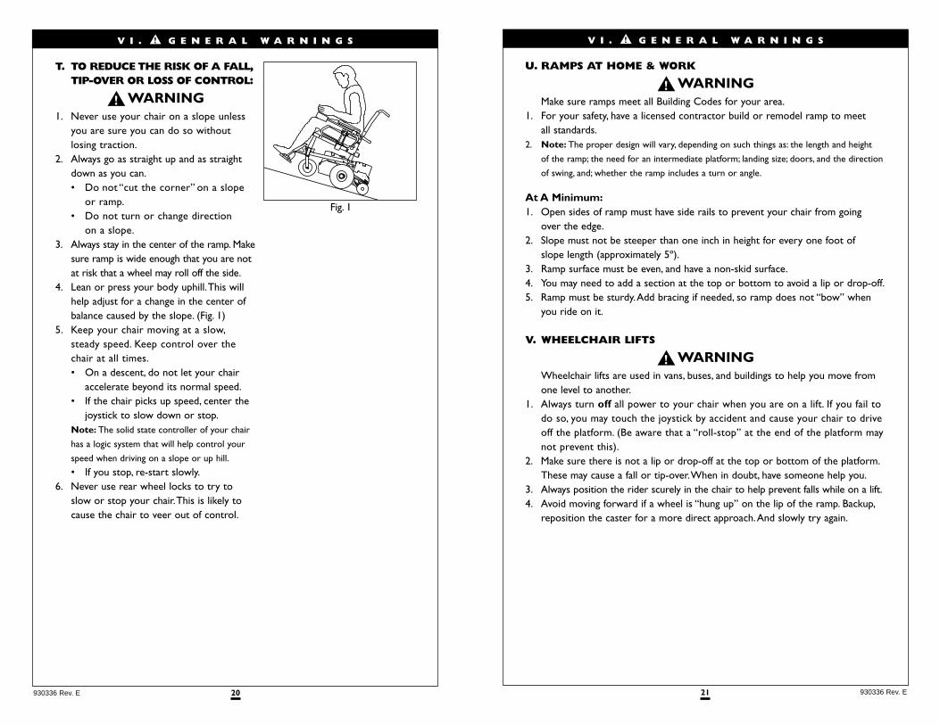
T. TO REDUCE THE RISK OF A FALL,TIP-OVER OR LOSS OF CONTROL:
1. Never use your chair on a slope unlessyou are sure you can do so without losing traction.
2. Always go as straight up and as straightdown as you can.• Do not “cut the corner” on a slope
or ramp.• Do not turn or change direction
on a slope.3. Always stay in the center of the ramp. Make
sure ramp is wide enough that you are notat risk that a wheel may roll off the side.
4. Lean or press your body uphill.This willhelp adjust for a change in the center ofbalance caused by the slope. (Fig. 1)
5. Keep your chair moving at a slow,steady speed. Keep control over thechair at all times.• On a descent, do not let your chair
accelerate beyond its normal speed.• If the chair picks up speed, center the
joystick to slow down or stop.Note: The solid state controller of your chair
has a logic system that will help control your
speed when driving on a slope or up hill.
• If you stop, re-start slowly.6. Never use rear wheel locks to try to
slow or stop your chair.This is likely tocause the chair to veer out of control.
23 930336 Rev. E
V I I . W A R N I N G S : C O M P O N E N T S & O P T I O N S
Note: If you use parts or make changes not authorized by Sunrise it may create
a safety hazard and will void the Warranty.
A. ANTI-TIP LEVERS
Never remove or alter anti-tip levers.They help keep your chair from tippingover backward in normal use. Make sure rubber rollers are in good condition.
B. ARMRESTS
Armrests detach and will not bear the weight of this chair.1. Never lift this chair by its armrests.They may come loose or break.2. Lift this chair only by non-detachable parts of the main frame.
C. BATTERIES
1. Only deep cycle sealed case construction batteries should be used in this device.
2. To prevent an acid spill, always keep batteries upright (wet cell batteries).3. Never smoke or hold an open flame near batteries.They are a known
explosion hazard.4. Always wear rubber gloves and safety glasses when you handle batteries.5. Read all of section XI Batteries before attempting to change, or charge batteries.
D. CUSHIONS & SLING SEATS
1. Quickie sling seats, standard foam cushions, and other body supports, are not designed for the relief of pressure.
2. If you suffer from pressure sores, or if you are at risk that they will occur, you may need a special seat system or a device to control your posture.• Consult your doctor, nurse or therapist to find out if you need such a
device for your well-being.
22930336 Rev. E
W. CURBS & SINGLE STEPS
1. Your chair is not designed to drive up or down a curb or step more thantwo (2) inches (5 cm) high. Doing so may:• Result in a fall or tip-over.• Damage the frame, wheels, axles or other chair parts, or loosen fasteners.
2. To prevent a fall or tip-over, use wheelchair access ramps or have someone help you.
3. If you must climb or descend a curb or step alone do so at your own risk and use extreme care.• Go as straight up or straight down as you can. Never turn or climb or
descend at an angle as a fall or tip-over is likely.• Proceed slowly, at a steady speed.
4. Make sure that persons who assist you review the “Tips For Attendants” and heed all warnings.
X. STAIRS
Never use this chair to go up or down stairs, even with an attendant.Doing so is likely to cause a fall or tip-over.
Y. ESCALATORS
Never take this chair on an escalator, even with an attendant. Doing so islikely to cause a fall or tip-over.
V I . G E N E R A L W A R N I N G S
25 930336 Rev. E
V I I . W A R N I N G S : C O M P O N E N T & O P T I O N S
I. PNEUMATIC TIRES
Proper inflation extends the life of your tires and makes your chair easier to use.1. Do not use this chair if any of the tires are under- or over-inflated. Check
weekly for proper inflation level, as listed on the tire sidewall.2. Low pressure in a tire may cause the chair to veer to one side and result in a
loss of control.3. An over-inflated tire may burst.4. Never use a gas station air pump to inflate a tire. Such pumps provide air at
high volume, and could cause the tire to burst.To prevent tire damage:• Use a hand pump (or a low volume air pump) to inflate tires.• Use a tire gauge to check pressure.
5. Driving over sharp objects may cause damage to pneumatic tires and tubes.
J. POSITIONING BELTS (OPTIONAL)
Use a positioning belt only to help support your posture. Improper use ofsuch belts may cause severe injury or death.
1. Make sure you are not at risk to slide down in the wheelchair seat. If this occurs,you may suffer chest compression or suffocate due to pressure from the belt.
2. A pelvic wedge or a similar device can help keep you from sliding down in the seat. Consult your health care professional to find out if you need such a device.
3. The belt must be snug, but must not be so tight that it interferes with breathing.You should be able to slide your open hand, flat, between the belt and your stomach.
4. Make sure you can easily remove the belt in an emergency.5. Never use a positioning belt:
• In place of a motor vehicle seat belt. In an accident or sudden stop you may be thrown from the chair.A positioning belt will not prevent this,and further injury may result from the belt.
• As a restraint.A restraint requires a doctor’s order.• On a rider who is comatose or agitated.
K. PUSH HANDLES
1. Push handles provide secure points for an attendant to propel and control thechair.This helps to prevent a fall or tip-over.
2. Check to make sure push handle grips will not rotate or slip off.
24930336 Rev. E
E. FASTENERS
Many of the screws, bolts and nuts on this chair are special high-strength fasteners. Use of improper fasteners may cause your chair to fail.
1. Only use fasteners provided by Sunrise.2. If fasteners become loose, tighten them as soon as you can.3. Over- or under-tightened fasteners may fail or cause damage to chair parts.
• See Section IX, “Set-Up,Adjustment & Use”, for proper torque settings.
F. FOOTRESTS
1. At the lowest point, footrests should be at least 21/2 inches (65 mm) off theground. If set too LOW, they may “hang up” on obstacles you can expect to findin normal use.This may cause the chair to stop suddenly and tip forward.
2. To avoid a trip or fall when you transfer:• Make sure your feet do not “hang up” or get caught in the space
between the footrests.• Avoid putting weight on the footrests, as the chair may tip forward.• Remove or swing the footrests out of the way, if possible.
3. Never lift this chair by the footrests. Footrests detach and will not bear the weight of this chair. Lift this chair only by non-detachable parts of the main frame.
G. MOTOR LOCKS
1. Do not engage or disengage motor locks unless power to the chair is off.2. With the brakes released, the chair will not operate and the battery charge
indicator will flash 9 bars rapidly (if power to the chair is on).3. Be aware that the chair will not have brakes when motor locks are in the
free-wheel position.4. Make sure that the person pushing the chair has full control when motor
locks are disengaged.
H. ON/OFF SWITCH
1. Never use the ON/OFF switch to stop the chair except in an emergency.This will result in an abrupt stop, and may cause you to fall.
2. To slow your chair to a stop, return the joystick to neutral.
V I I . W A R N I N G S : C O M P O N E N T S & O P T I O N S
27 930336 Rev. E
V I I I . T I P S F O R A T T E N D A N T S
1. Persons who help a rider do one of the following tasks should review and heed the
warnings “Notice to Attendants” and all warnings in this Manual for that task.
2. The “Tips” that follow are suggestions only. Be aware that you will need to learn
safe methods best suited to the rider and to your abilities. Consult your health
care professional for instructions.
A. TO CLIMB A CURB OR SINGLE STEP
The following is one way to safely help a rider climb a curb or single stepgoing forward:
1. Stay behind the chair.2. Face the curb and tilt the chair up on the rear wheels so that the front casters
clear the curb or step.3. Move forward, placing the front casters on the upper level as soon as you are
sure they are past the edge.4. Continue forward until the rear wheels contact the face of the curb or step.
Lift and roll the rear wheels to the upper level.
B. TO DESCEND A CURB OR SINGLE STEP
The following is one way to safely help a rider descend a curb or single stepgoing backward:
1. Stay at the rear of the chair.2. Several feet before your reach the edge of the curb or step, turn the chair
around and pull it backward.3. Proceed carefully. Look over your shoulder and carefully step back until you
are off the curb or stair and standing on the lower level.4. Pull the chair toward you until the rear wheels reach the edge of the curb or
step.Then allow the rear wheels to slowly roll down onto the lower level.5. When the rear wheels are safely on the lower level, tilt the chair back to its
balance point.This will lift the front casters off the curb or step.6. Keep the chair in balance and take small steps backward. Be sure to look
where you are going.Turn the chair around and gently lower front casters to the ground.
26930336 Rev. E
V I I . W A R N I N G S : C O M P O N E N T S & O P T I O N S
L. REAR WHEEL LOCKS (OPTIONAL)
If you request them, we will install rear wheel locks at Sunrise.1. Rear wheel locks are not designed to slow or stop a moving wheelchair.
Never apply them when your chair is moving. Doing so may cause you to veer out of control.• Use wheel locks only to keep the rear wheels from rolling when your
chair is at a complete stop.2. Low pressure in a rear tire may cause the wheel lock on that side to slip and
may allow the wheel to turn when you do not expect it.3. Make sure lock arms embed in tires at least 3/8 inch (9.5 mm) when locked. If
you fail to do so, the locks may not work.
M.SEATING SYSTEMS
1. Use of a seating system not approved by Sunrise may alter the center of balance of this chair.This may cause a fall or tip-over.
2. Never change the seating system of your chair unless you consult your supplier first.
N.UPHOLSTERY FABRIC
1. Replace worn or torn fabric of seat sling and seat back as soon as you can. If you fail to do so, the seat may fail and cause you to fall.Worn fabrics mayincrease the potential for a fire hazard.
2. Sling fabric will deteriorate with age and use. Look for fraying, thin spots, orstretching of fabric at rivet holes. Replace fabric as required.
3. “Dropping down” into sling seat will weaken fabric and result in the need toinspect and replace sling on a more frequent basis.
4. Be aware that washing may reduce flame retardation of the fabric.
29 930336 Rev. E
I X . S E T - U P , A D J U S T M E N T & U S E
TOOLS YOU WILL NEED 1. Basic Tool Kit:
To set-up, adjust and maintain your chair you will need the following tools:• 7/16" box and open-end wrench• 1/2" box and open-end wrench• 3/4" box and open-end wrench• 5/32" Allen wrench• 3/16" Allen wrench• 1/8" Allen wrench• Phillips screwdriver #2• Custom axle wrench (or a 1/2" open-end wrench) You can obtain a multi-purpose tool kit from Sunrise, or buy the tools youneed from a hardware store.
2. Torque Wrench:If you plan to adjust and maintain this chair yourself, Quickie recommends that youuse a torque wrench.Note:The wrench must measure inch-pounds (N.m). You can buy a torque wrench and
proper sockets from a hardware store.
CHECK-OUT Be sure this chair performs to your chosen operational settings. If it does not,turn the chair off immediately and reprogram with the Quickie QTRONIXProgrammer. If you do not own a Quickie QTRONIX Programmer have yoursupplier reprogram your wheelchair as needed. Or, you can order a QuickieQTRONIX Programmer for your own use from your supplier.Note: Repeat this procedure until the chair performs to your specifications
When properly set-up, this chair will operate smoothly. Check to see that all components
work properly. If you detect a problem, be sure to correct it before use.
28930336 Rev. E
NOTES 1. Work Surface For Set-Up:
Use a flat surface, such as a table, to assemble, adjust and check your chair.This makes the steps easier and helps ensure a correct set-up.
2. Fasteners:• Many of the screws and bolts on this chair are special high-strength fasteners
and may have special coatings.• Many nuts are of the Nylock type.They have a plastic insert to help
prevent loosening.• Only use screws, bolts and nuts provided by Sunrise.
1. Use of improper fasteners may cause the chair to fail.
2. Over-or under- tightened fasteners may fail or cause damage to chair parts.
3. If bolts or screws become loose,tighten them as soon as you can. Loose bolts or
screws can cause damage to other chair parts causing them to fail.
3. Washers & Spacers:• Note the position of washers and spacers before disassembly.• To avoid damage to the frame, replace all washers and spacers when you
reassemble parts.4. Torque Settings:
• A torque setting is the optimal tightening for a particular fastener. Use atorque wrench that measures inch-pounds to secure screws, nuts and boltson this chair.
• Note: unless otherwise noted, use a torque setting of 120 inch-pounds (13.5 N.m)
for all fasteners.
I X . S E T - U P , A D J U S T M E N T & U S E
31 930336 Rev. E
I X . S E T - U P , A D J U S T M E N T & U S E
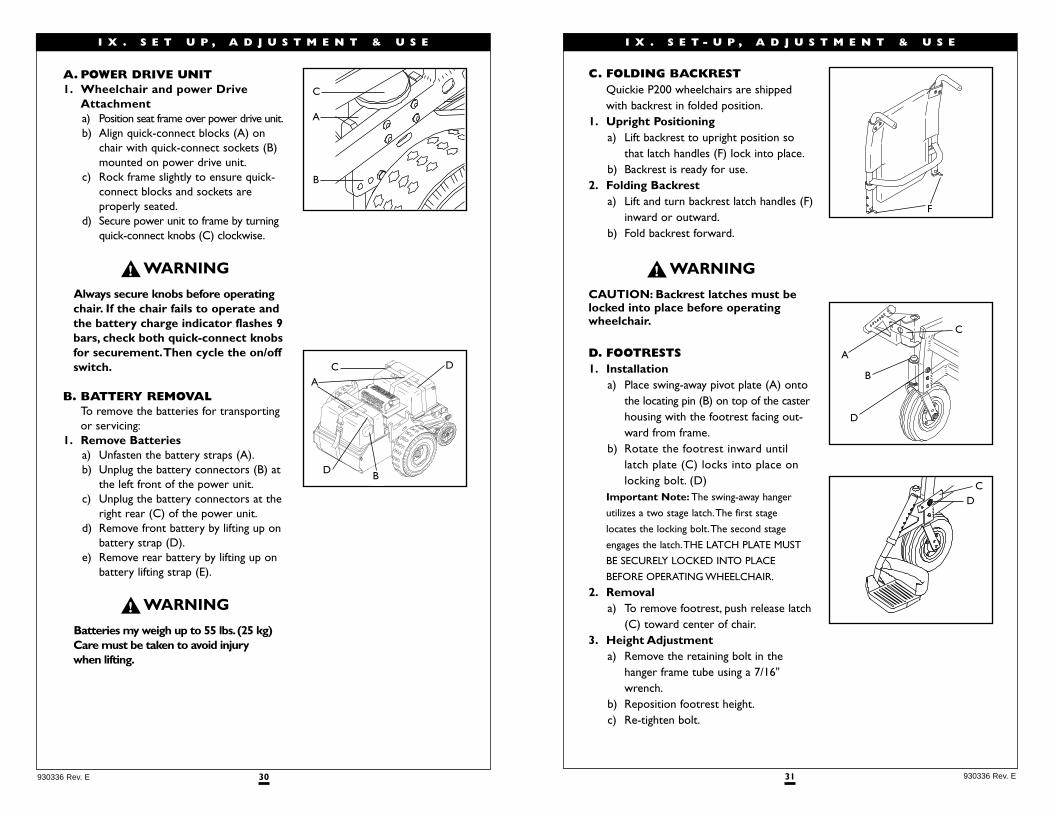
C. FOLDING BACKREST Quickie P200 wheelchairs are shippedwith backrest in folded position.
1. Upright Positioninga) Lift backrest to upright position so
that latch handles (F) lock into place.b) Backrest is ready for use.
2. Folding Backresta) Lift and turn backrest latch handles (F)
inward or outward.b) Fold backrest forward.
CAUTION: Backrest latches must belocked into place before operatingwheelchair.
D. FOOTRESTS1. Installation
a) Place swing-away pivot plate (A) ontothe locating pin (B) on top of the casterhousing with the footrest facing out-ward from frame.
b) Rotate the footrest inward untillatch plate (C) locks into place onlocking bolt. (D)
Important Note: The swing-away hanger
utilizes a two stage latch.The first stage
locates the locking bolt.The second stage
engages the latch.THE LATCH PLATE MUST
BE SECURELY LOCKED INTO PLACE
BEFORE OPERATING WHEELCHAIR.
2. Removala) To remove footrest, push release latch
(C) toward center of chair.3. Height Adjustment
a) Remove the retaining bolt in the hanger frame tube using a 7/16"wrench.
b) Reposition footrest height.c) Re-tighten bolt.
F
A
B
D
C
DC
30930336 Rev. E
I X . S E T U P , A D J U S T M E N T & U S E
A. POWER DRIVE UNIT1. Wheelchair and power Drive
Attachmenta) Position seat frame over power drive unit.b) Align quick-connect blocks (A) on
chair with quick-connect sockets (B)mounted on power drive unit.
c) Rock frame slightly to ensure quick-connect blocks and sockets are properly seated.
d) Secure power unit to frame by turningquick-connect knobs (C) clockwise.
Always secure knobs before operatingchair. If the chair fails to operate andthe battery charge indicator flashes 9bars, check both quick-connect knobsfor securement.Then cycle the on/offswitch.
B. BATTERY REMOVALTo remove the batteries for transportingor servicing:
1. Remove Batteriesa) Unfasten the battery straps (A).b) Unplug the battery connectors (B) at
the left front of the power unit.c) Unplug the battery connectors at the
right rear (C) of the power unit.d) Remove front battery by lifting up on
battery strap (D).e) Remove rear battery by lifting up on
battery lifting strap (E).
Batteries my weigh up to 55 lbs.(25 kg)Care must be taken to avoid injury when lifting.
A
C
B
CA
D B
D
33 930336 Rev. E
I X . S E T - U P , A D J U S T M E N T & U S E
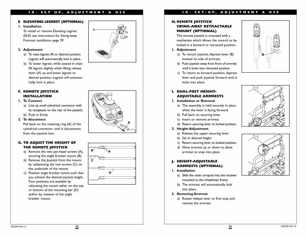
H. REMOTE JOYSTICK SWING-AWAY RETRACTABLEMOUNT (OPTIONAL)The remote joystick is mounted with amechanism which allows the control to belocked in a forward or retracted position.
1. Adjustmenta) To retract joystick, depress lever (B)
located on side of armrest.b) Push joystick away from front of armrest
until it locks into retracted position.c) To return to forward position, depress
lever and push joystick forward until itlocks into place.
I. DUAL-POST HEIGHT-ADJUSTABLE ARMRESTS
1. Installation or Removala) The assembly is held securely in place
when the lever is facing forward.b) Pull back on securing lever.c) Insert or remove armrest.d) Return securing lever to locked position.
2. Height-Adjustmenta) Release the upper securing lever.b) Set at desired heightc) Return securing lever to locked position.d) Move armrest up or down to allow
armrest to snap into place
J. HEIGHT-ADJUSTABLE ARMRESTS (OPTIONAL)
1. Installationa) Slide the outer armpost into the receiver
mounted to the wheelchair frame.b) The armrest will automatically lock
into place.2. Removing Armrest
a) Rotate release lever to first stop andremove the armrest
B
32930336 Rev. E
I X . S E T U P , A D J U S T M E N T & U S E
E ELEVATING LEGREST (OPTIONAL)1. Installation
To install or remove Elevating Legrest(ELR) see instructions for Swing-awayFootrest installation page 29.
2. Adjustmenta) To raise legrest, lift to desired position.
Legrest will automatically lock in place.b) To lower legrest, while seated in chair,
lift legrest slightly while lifting releaselever (A) up and lower legrest todesired position. Legrest will automat-ically lock in place.
F. REMOTE JOYSTICK INSTALLATION
1. To Connecta) Line up small cylindrical connector with
its receptacle on the rear of the joystick.b) Push in firmly.
2. To disconnectPull back on the retaining ring (A) of thecylindrical connector until it disconnectsfrom the joystick box.
G. TO ADJUST THE HEIGHT OF THE REMOTE JOYSTICKa) Remove the two pan-head screws (A),
securing the angle bracket mount (B).b) Remove the Joystick from the mount
by unfastening the two screws (C) onthe underside of the mount.
c) Position angle bracket mount such thatyou achieve the desired joystick height.Four positions are available byrelocating the mount either on the topor bottom of the mounting bar (D)and/or by rotation of the anglebracket mount.
A
A
A
C
B
D
35 930336 Rev. E
I X . S E T - U P , A D J U S T M E N T & U S E
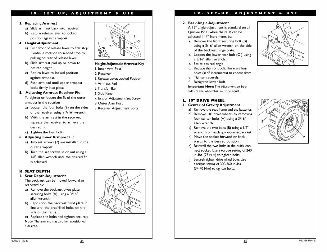
2. Back Angle AdjustmentA 12º angle-adjustment is standard on allQuickie P200 wheelchairs. It can beadjusted in 4° increments by:a. Remove the front securing bolt (B)
using a 3/16" allen wrench on the sideof the backrest hinge plate.
b. Loosen the lower rear bolt (C ) usinga 3/16" allen wrench.
c. Set at desired angled. Replace the front bolt.There are four
holes (in 4º increments) to choose frome. Tighten securely.f. Retighten lower bolt.Important Note: The adjustment on both sides of the wheelchair must be equal.
L. 10" DRIVE WHEEL1. Center of Gravity Adjustment
a) Remove the seat frame and the batteries.b) Remove 10” drive wheels by removing
four center bolts (A) using a 3/16" allen wrench.
c) Remove the two bolts (B) using a 1/2"wrench from each quick-connect socket.
d) Move the socket forward or back-wards to the desired position.
e) Reinstall the two bolts in the quick-con-nect socket. Use a torque setting of 240in.-lbs. (27 N.m) to tighten bolts.
f) Securely tighten drive wheel bolts.Use a torque setting of 300-360 in.-lbs.(34-40 N.m) to tighten bolts.
B
A
BC
34930336 Rev. E
I X . S E T U P , A D J U S T M E N T & U S E
3. Replacing Armresta) Slide armrest back into receiver.b) Return release lever to locked
position against armpost4. Height-Adjustment
a) Push front of release lever to first stop.Continue rotation to second stop bypulliing on rear of release lever.
b) Slide armrest pad up or down todesired height.
c) Return lever to locked positionagainst armpost.
d) Push arm pad until upper armpostlocks firmly into place.
5. Adjusting Armrest Receiver FitTo tighten or loosen the fit of the outerarmpost in the receiver:a) Loosen the four bolts (9) on the sides
of the receiver using a 7/16" wrench.b) With the armrest in the receiver,
squeeze the receiver to achieve thedesired fit.
c) Tighten the four bolts.6. Adjusting Inner Armpost Fit
a) Two set screws (7) are installed in theouter armpost.
b) Turn the set screws in or out using a1/8" allen wrench until the desired fitis achieved.
K. SEAT DEPTH1. Seat Depth Adjustment
The backrest can be moved forward orrearward by:a) Remove the backrest pivot plate
securing bolts (A) using a 3/16" allen wrench.
b) Reposition the backrest pivot plate inline with the predrilled holes on theside of the frame.
c) Replace the bolts and tighten securely.Note: The armrest may also be repositioned if desired.
A
9
26
7
1 4
3
5
8
Height-Adjustable Armrest Key1. Inner Arm Post2. Receiver3. Release Lever, Locked Position4.Armrest Pad5.Transfer Bar6. Side Panel7.Tension Adjustment Set Screw8. Outer Arm Post9. Receiver Adjustment Bolts
37 930336 Rev. E
I X . S E T - U P , A D J U S T M E N T & U S E
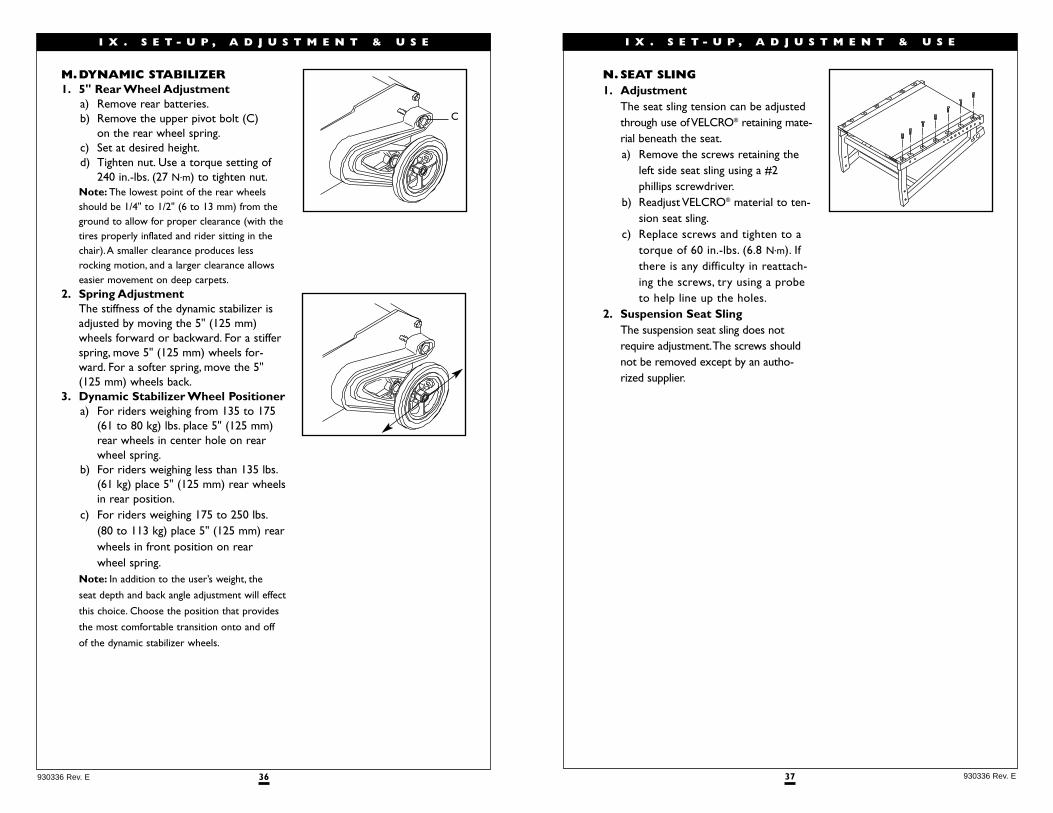
N.SEAT SLING1. Adjustment
The seat sling tension can be adjustedthrough use of VELCRO® retaining mate-rial beneath the seat.a) Remove the screws retaining the
left side seat sling using a #2phillips screwdriver.
b) Readjust VELCRO® material to ten-sion seat sling.
c) Replace screws and tighten to atorque of 60 in.-lbs. (6.8 N.m). Ifthere is any difficulty in reattach-ing the screws, try using a probeto help line up the holes.
2. Suspension Seat SlingThe suspension seat sling does notrequire adjustment.The screws shouldnot be removed except by an autho-rized supplier.
36930336 Rev. E
I X . S E T - U P , A D J U S T M E N T & U S E
M.DYNAMIC STABILIZER1. 5" Rear Wheel Adjustment
a) Remove rear batteries.b) Remove the upper pivot bolt (C)
on the rear wheel spring.c) Set at desired height.d) Tighten nut. Use a torque setting of
240 in.-lbs. (27 N.m) to tighten nut.Note: The lowest point of the rear wheels should be 1/4" to 1/2" (6 to 13 mm) from the ground to allow for proper clearance (with the tires properly inflated and rider sitting in the chair).A smaller clearance produces less rocking motion, and a larger clearance allows easier movement on deep carpets.
2. Spring AdjustmentThe stiffness of the dynamic stabilizer isadjusted by moving the 5" (125 mm)wheels forward or backward. For a stifferspring, move 5" (125 mm) wheels for-ward. For a softer spring, move the 5"(125 mm) wheels back.
3. Dynamic Stabilizer Wheel Positionera) For riders weighing from 135 to 175
(61 to 80 kg) lbs. place 5" (125 mm)rear wheels in center hole on rearwheel spring.
b) For riders weighing less than 135 lbs.(61 kg) place 5" (125 mm) rear wheelsin rear position.
c) For riders weighing 175 to 250 lbs.(80 to 113 kg) place 5" (125 mm) rearwheels in front position on rear wheel spring.
Note: In addition to the user’s weight, the
seat depth and back angle adjustment will effect
this choice. Choose the position that provides
the most comfortable transition onto and off
of the dynamic stabilizer wheels.
C
39 930336 Rev. E
I X . S E T - U P , A D J U S T M E N T & U S E
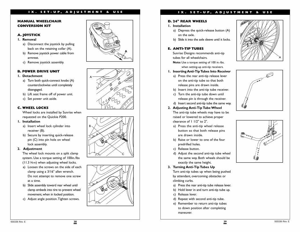
D. 24" REAR WHEELS1. Installation
a) Depress the quick-release button (A)on the axle.
b) Slide it into the axle sleeve until it locks.
E. ANTI-TIP TUBESSunrise Designs recommends anti-tiptubes for all wheelchairs.Note: Use a torque setting of 100 in.-lbs.
when setting-up anti-tip receivers.
1. Inserting Anti-Tip Tubes Into Receivera) Press the rear anti-tip release lever
on the anti-tip tube so that bothrelease pins are drawn inside.
b) Insert into the anti-tip tube receiver.c) Turn the anti-tip tube down until
release pin is through the receiver.d) Insert second anti-tip tube the same way.
2. Adjusting Anti-Tip Tube WheelThe anti-tip tube wheels may have to beraised or lowered to achieve properclearance of 1 1/2" to 2".a) Press the anti-tip wheel release
button so that both release pins are drawn inside.
b) Raise or lower to one of the fourpredrilled holes.
c) Release button.d) Adjust the second anti-tip tube wheel
the same way. Both wheels should beexactly the same height.
3. Turning Anti-Tip Tubes UpTurn anti-tip tubes up when being pushedby attendant, overcoming obstacles orclimbing curbs.a) Press the rear anti-tip tube release lever.b) Hold lever in and turn anti-tip tube up.c) Release lever.d) Repeat with second anti-tip tube.e) Remember to return anti-tip tubes
to down position after completingmaneuver.
A
38930336 Rev. E
I X . S E T - U P , A D J U S T M E N T & U S E
A
C
B
MANUAL WHEELCHAIR CONVERSION KIT
A. JOYSTICK1. Removal
a) Disconnect the joystick by pullingback on the retaining collar (A).
b) Remove joystick power cable from armrest.
c) Remove joystick assembly.
B. POWER DRIVE UNIT1. Detachment
a) Turn both quick-connect knobs (A)counterclockwise until completely disengaged.
b) Lift seat frame off of power unit.c) Set power unit aside.
C. WHEEL LOCKSWheel locks are installed by Sunrise whenrequested on the Quickie P200.
1. Installationa) Insert wheel lock cylinder into
receiver (B).b) Secure by inserting quick-release
pin (C) into pin hole on wheel lock assembly.
2. AdjustmentThe wheel lock mounts on a split clampsystem. Use a torque setting of 100in./lbs(11.3 N.m) when adjusting wheel locks.a) Loosen the screws on the side of each
clamp using a 3/16" allen wrench.Do not attempt to remove one screwat a time.
b) Slide assembly toward rear wheel untilclamp embeds into tire to prevent wheelmovement, when in locked position.
c) Adjust angle position.Tighten screws.
A
41 930336 Rev. E
X . O P E R A T I N G G U I D E
A. PERFORMANCE CONTROL SETTINGS1. It is vital to match control settings to your level of function and ability.2. Consult your health care professional and your supplier to select the best
control settings for you.3. Check and adjust the settings every six to twelve months (or more often, if needed).4. Adjust the control settings immediately if you notice any change in
your ability to:• Control the joystick.• Hold your torso erect.• Avoid running into objects.
5. Control Settings are adjusted through the use of the Quickie QTRONIXProgrammer. See your supplier if you do not own a Quickie QTRONIXProgrammer pad.
40930336 Rev. E
I X . S E T - U P , A D J U S T M E N T & U S E
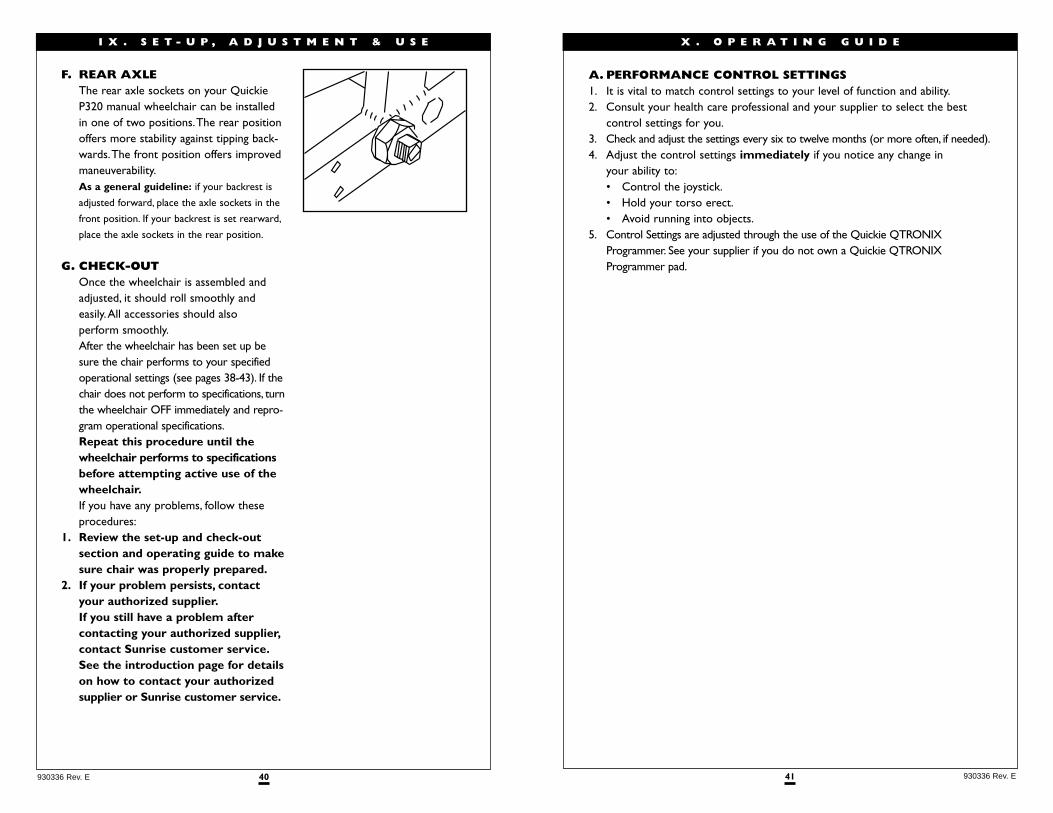
F. REAR AXLEThe rear axle sockets on your QuickieP320 manual wheelchair can be installedin one of two positions.The rear positionoffers more stability against tipping back-wards.The front position offers improvedmaneuverability.As a general guideline: if your backrest is
adjusted forward, place the axle sockets in the
front position. If your backrest is set rearward,
place the axle sockets in the rear position.
G. CHECK-OUTOnce the wheelchair is assembled andadjusted, it should roll smoothly and easily.All accessories should also perform smoothly.After the wheelchair has been set up besure the chair performs to your specifiedoperational settings (see pages 38-43). If thechair does not perform to specifications, turnthe wheelchair OFF immediately and repro-gram operational specifications.Repeat this procedure until thewheelchair performs to specificationsbefore attempting active use of thewheelchair.If you have any problems, follow theseprocedures:
1. Review the set-up and check-out section and operating guide to makesure chair was properly prepared.
2. If your problem persists, contactyour authorized supplier.If you still have a problem after contacting your authorized supplier,contact Sunrise customer service.See the introduction page for detailson how to contact your authorizedsupplier or Sunrise customer service.
43 930336 Rev. E
X . O P E R A T I N G G U I D E
C. THERMAL ROLL-BACK Your chair has a thermal roll back circuit.This protects the controller from damagedue to overheating. In extreme conditions(such as repetitive hill climbing) the circuitwill decrease the power to your motors.This allows the chair to operate at areduced speed.When the controller cools,the chair will return to normal speed.
D. CIRCUIT BREAKERS 1. Notes:
Your Quickie P200 has two battery boxes,with a circuit breaker on each box.• In the unlikely event of a short circuit
or heavy overload, all power to your chair will be shut off.
• To reset your chair, depress the circuit breaker button(s) on the front of the battery boxes.A few minutes wait is required before the circuit breaker(s) will reset.
2. Repeated Shutdown:If the chair continues to shut down after resetting, have it serviced by a supplier.
42930336 Rev. E
X . O P E R A T I N G G U I D E
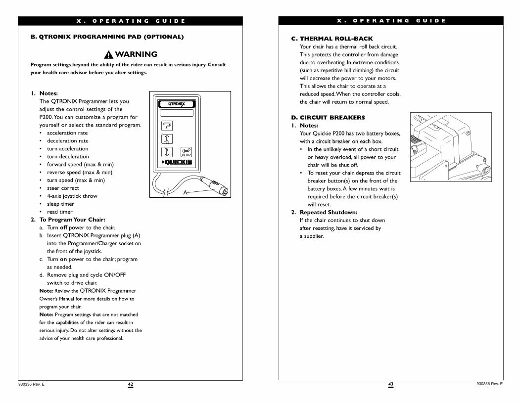
B. QTRONIX PROGRAMMING PAD (OPTIONAL)
Program settings beyond the ability of the rider can result in serious injury. Consult
your health care advisor before you alter settings.
1. Notes:The QTRONIX Programmer lets youadjust the control settings of the P200.You can customize a program foryourself or select the standard program.• acceleration rate• deceleration rate• turn acceleration• turn deceleration• forward speed (max & min)• reverse speed (max & min)• turn speed (max & min)• steer correct• 4-axis joystick throw• sleep timer• read timer
2. To Program Your Chair:a. Turn off power to the chair.b. Insert QTRONIX Programmer plug (A)
into the Programmer/Charger socket onthe front of the joystick.
c. Turn on power to the chair; program as needed.
d. Remove plug and cycle ON/OFFswitch to drive chair.
Note: Review the QTRONIX ProgrammerOwner’s Manual for more details on how to
program your chair.
Note: Program settings that are not matched
for the capabilities of the rider can result in
serious injury. Do not alter settings without the
advice of your health care professional.
A
45 930336 Rev. E
• To exit drive or actuator mode select, simply push the on/off/mode toggleup one or more times until the indicator no longer flashes, or push thejoystick forward or reverse to begin driving.
5. Joystick (E):The joystick controls the direction and speed of your chair.Turn the chair onand move the joystick in the direction you want to go.• Moving the joystick from the neutral (center) position disengages the
motor locks, allowing the chair to move.• The chair will move faster the more you move the joystick away
from neutral.Note: If your speed becomes hard to manage, release the Joystick and the chair will
come to a complete stop.
• When you release the joystick it will return to neutral; the chair will slowto a stop and the motor locks will reengage.
• We recommend that you switch the chair off if you stop for any length oftime.This will conserve battery power.
Note: Once the chair stops, switching the chair off will not affect the motor locks.
6. Joystick Boot(F):Make sure the boot is not torn or cracked (this could allow debris,water or moistureto enter). If the boot is torn or cracked, replace it as soon as you can.
7. Remote Switch Jacks (optional) (I):Two 1/8” switch jacks are optional to provide remote switch control of the on/offpower function and the mode select function. Any of the single switches offered bySunrise Medical can be used to connect to either or both of these jacks (except thesingle zero touch switch).
1. Never use the ON/OFF switch to stop your chair except in an emergency.This will
result in an abrupt stop, and may cause you to fall.
2. To slow or stop your chair, return the joystick to neutral.
X . O P E R A T I N G G U I D E
44930336 Rev. E
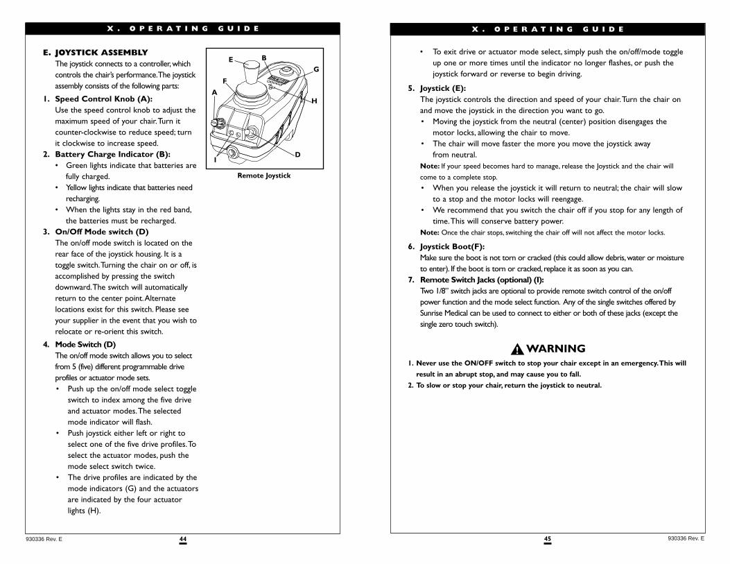
E. JOYSTICK ASSEMBLYThe joystick connects to a controller,whichcontrols the chair’s performance.The joystickassembly consists of the following parts:
1. Speed Control Knob (A):Use the speed control knob to adjust themaximum speed of your chair.Turn itcounter-clockwise to reduce speed; turnit clockwise to increase speed.
2. Battery Charge Indicator (B):• Green lights indicate that batteries are
fully charged.• Yellow lights indicate that batteries need
recharging.• When the lights stay in the red band,
the batteries must be recharged.3. On/Off Mode switch (D)
The on/off mode switch is located on therear face of the joystick housing. It is atoggle switch.Turning the chair on or off, isaccomplished by pressing the switchdownward.The switch will automaticallyreturn to the center point.Alternatelocations exist for this switch. Please seeyour supplier in the event that you wish torelocate or re-orient this switch.
4. Mode Switch (D)The on/off mode switch allows you to selectfrom 5 (five) different programmable driveprofiles or actuator mode sets.• Push up the on/off mode select toggle
switch to index among the five driveand actuator modes.The selectedmode indicator will flash.
• Push joystick either left or right toselect one of the five drive profiles.Toselect the actuator modes, push themode select switch twice.
• The drive profiles are indicated by themode indicators (G) and the actuatorsare indicated by the four actuatorlights (H).
X . O P E R A T I N G G U I D E
A
D
E
F
G
H
B
Remote Joystick
I
47 930336 Rev. E
A. INTRODUCTION 1. Notes:
• Batteries supply the power for your chair.They contain a finite amount of energy and have limits on how long they can store and supply energy.
• You can charge batteries only a certain number of times before they willfail and no longer hold a charge.
• For answers to questions about batteries, consult your supplier.2. Use Proper Batteries:
Your chair operates on two 12 volt batteries.• They should be Group 24 size with a minimum of 65 ampere hour rating.
Only deep cycle sealed case construction batteries should be used in this device.
• Connecting configuration.They should have a post and clamp style connection.
• When you buy a replacement, insist on a deep cycle sealed case type.Do not use a car starter battery.
3. Breaking In:• A battery requires “breaking-in” for the first 6 to 12 charges. It will not
accept a full charge for this period.• It is best to limit the length of your trips until you break the batteries in
and you know the range of your chair.4. Discharged Batteries:
• Never allow a battery to completely discharge. If you operate your wheelchair until it has almost stopped, you will greatly reduce the life of your batteries.
• Never let a battery sit in a discharged condition. Give unused or stored batteries a full charge once per month.
• Always fully charge the batteries. Avoid “topping Off” with frequent charges.
Never connect a life support or auxiliary device to a wheelchair battery. The electrical
system may fail, and result in severe injury to or death of rider.
X I . B A T T E R I E S
46930336 Rev. E
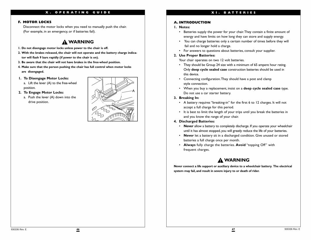
F. MOTOR LOCKS Disconnect the motor locks when you need to manually push the chair.(For example, in an emergency, or if batteries fail).
1. Do not disengage motor locks unless power to the chair is off.
2. With the brakes released, the chair will not operate and the battery charge indica-
tor will flash 9 bars rapidly (if power to the chair is on).
3. Be aware that the chair will not have brakes in the free-wheel position.
4. Make sure that the person pushing the chair has full control when motor locks
are disengaged.
1. To Disengage Motor Locks:a. Lift the lever (A) to the free-wheelposition.
2. To Engage Motor Locks:a. Push the lever (A) down into the
drive position.
A
X . O P E R A T I N G G U I D E
49 930336 Rev. E
C. ACID BURNS (unsealed wet cell batteries)Acid in batteries is corrosive. It can cause serious burns to the eyes and skinand can damage floors, furniture, clothing and your wheelchair.
1. Use extreme care not to spill acid when you handle batteries. Keep batteries upright.
2. Avoid contact of acid with bare skin or clothing.
3. Always wear rubber gloves and safety glasses when you handle batteries.
4. If acid contacts your skin or clothing, wash immediately with soap and water.
5. If acid contacts your eyes, immediately flood eyes with cold running water for at
least 15 minutes. Seek medical attention immediately.
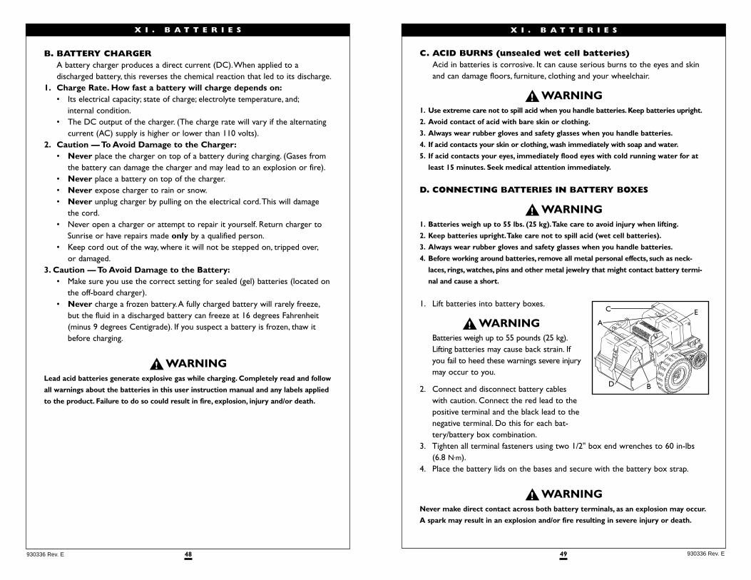
D. CONNECTING BATTERIES IN BATTERY BOXES
1. Batteries weigh up to 55 lbs. (25 kg).Take care to avoid injury when lifting.
2. Keep batteries upright.Take care not to spill acid (wet cell batteries).
3. Always wear rubber gloves and safety glasses when you handle batteries.
4. Before working around batteries, remove all metal personal effects, such as neck-
laces, rings, watches, pins and other metal jewelry that might contact battery termi-
nal and cause a short.
1. Lift batteries into battery boxes.
Batteries weigh up to 55 pounds (25 kg).Lifting batteries may cause back strain. Ifyou fail to heed these warnings severe injurymay occur to you.
2. Connect and disconnect battery cableswith caution. Connect the red lead to thepositive terminal and the black lead to thenegative terminal. Do this for each bat-tery/battery box combination.
3. Tighten all terminal fasteners using two 1/2" box end wrenches to 60 in-lbs(6.8 N.m).
4. Place the battery lids on the bases and secure with the battery box strap.
Never make direct contact across both battery terminals, as an explosion may occur.
A spark may result in an explosion and/or fire resulting in severe injury or death.
X I . B A T T E R I E S
C
A
D B
E
48930336 Rev. E
B. BATTERY CHARGER A battery charger produces a direct current (DC).When applied to a discharged battery, this reverses the chemical reaction that led to its discharge.
1. Charge Rate. How fast a battery will charge depends on:• Its electrical capacity; state of charge; electrolyte temperature, and;
internal condition.• The DC output of the charger. (The charge rate will vary if the alternating
current (AC) supply is higher or lower than 110 volts).2. Caution — To Avoid Damage to the Charger:
• Never place the charger on top of a battery during charging. (Gases from the battery can damage the charger and may lead to an explosion or fire).
• Never place a battery on top of the charger.• Never expose charger to rain or snow.• Never unplug charger by pulling on the electrical cord.This will damage
the cord.• Never open a charger or attempt to repair it yourself. Return charger to
Sunrise or have repairs made only by a qualified person.• Keep cord out of the way, where it will not be stepped on, tripped over,
or damaged.3. Caution — To Avoid Damage to the Battery:
• Make sure you use the correct setting for sealed (gel) batteries (located onthe off-board charger).
• Never charge a frozen battery.A fully charged battery will rarely freeze,but the fluid in a discharged battery can freeze at 16 degrees Fahrenheit (minus 9 degrees Centigrade). If you suspect a battery is frozen, thaw it before charging.
Lead acid batteries generate explosive gas while charging. Completely read and follow
all warnings about the batteries in this user instruction manual and any labels applied
to the product. Failure to do so could result in fire, explosion, injury and/or death.
X I . B A T T E R I E S
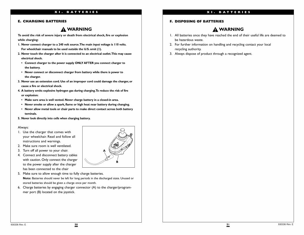
51 930336 Rev. E
X I . B A T T E R I E S
F. DISPOSING OF BATTERIES
1. All batteries once they have reached the end of their useful life are deemed tobe hazardous waste.
2. For further information on handling and recycling contact your local recycling authority.
3. Always dispose of product through a recognized agent.
50930336 Rev. E
X I . B A T T E R I E S
E. CHARGING BATTERIES
To avoid the risk of severe injury or death from electrical shock, fire or explosion
while charging:
1. Never connect charger to a 240 volt source.The main input voltage is 110 volts.
For wheelchair manuals to be used outside the U.S. omit (1).
2. Never touch the charger after it is connected to an electrical outlet.This may cause
electrical shock.
• Connect charger to the power supply ONLY AFTER you connect charger to
the battery.
• Never connect or disconnect charger from battery while there is power to
the charger.
3. Never use an extension cord. Use of an improper cord could damage the charger, or
cause a fire or electrical shock.
4. A battery emits explosive hydrogen gas during charging.To reduce the risk of fire
or explosion:
• Make sure area is well vented. Never charge battery in a closed-in area.
• Never smoke or allow a spark, flame or high heat near battery during changing.
• Never allow metal tools or chair parts to make direct contact across both battery
teminals.
5. Never look directly into cells when charging battery.
Always:1. Use the charger that comes with
your wheelchair. Read and follow allinstructions and warnings.
2. Make sure room is well ventilated.3. Turn off all power to your chair.4. Connect and disconnect battery cables
with caution. Only connect the chargerto the power supply after the chargerhas been connected to the chair
5. Make sure to allow enough time to fully charge batteries.Note: Batteries should never be left for long periods in the discharged state. Unused or
stored batteries should be given a charge once per month.
6. Charge batteries by engaging charger connector (A) to the charger/program-mer port (B) located on the joystick.
A
B
53 930336 Rev. E
D. BATTERY MAINTENANCE
1. To prevent an acid spill, always keep batteries upright (wet cell batteries).
2. Never smoke or hold an open flame near batteries.
3. Always wear rubber gloves and safety glasses when you handle batteries.
1. Maintenance Schedule:This varies for different types of batteries.Always follow the instructions supplied with your batteries.Note: Always wear rubber gloves and safety glasses when you handle or service batteries.
2. Adding Water: (Wet Cells Only)• Wet-type lead acid batteries need periodic replacement of water
due to evaporation.Note: use distilled water only.
• Check the battery fluid level about once a week.When you remove the stoppers (on top of the battery) there should be one-eighth to one-quarter of an inch of fluid above the internal plates. Do not overfill.
3. Corrosion:Check battery terminals often for corrosion.a. If corrosion is present, use a wire brush to clean the terminals.Note: Always wear safety glasses and rubber gloves.
b. Use baking soda to neutralize acid.c. Use petroleum jelly to re-grease the terminals after connecting cable to
battery. (Completely cover the terminal nut and bolt, cable clip and anyexposed cable with jelly).
4. For Answers To Questions: Contact your supplier.
X I I . M A I N T E N A N C E
52930336 Rev. E
X I I . M A I N T E N A N C E
A. NOTES 1. Proper maintenance will improve performance and extend the useful life
of your chair.2. Clean your chair regularly.This will help you find loose or worn parts and will
make your chair easier to use.3. To protect your investment, have all major service and repair work done by
your supplier.
1. Your chair needs regular maintenance for peak performance and to avoid injury
from chair failure, damage or premature wear.
2. Inspect and maintain this chair strictly per the “Maintenance Chart”. (p. 52)
3. If you detect a problem, make sure to service or repair the chair before use.
4. At least once a year, have a complete safety check and service of your chair
performed by a supplier.
B. CLEANING 1. Paint Finish:
• Clean the paint finish with mild soapy water monthly.• Protect the paint with a coat of non-abrasive auto wax every three months.
2. Motors:• Clean around motor area weekly with a slightly damp (not wet) cloth.• Wipe off or blow away any fluff, dust, or dirt on or around the motors.• Note: You do not need to grease or oil the chair.
3. Upholstery:• Hand-wash only as needed. Machine washing may damage fabric.• Drip-dry only. Heat from a dryer may damage fabric.Note: Washing the fabric may decrease fire retardant properties.
C. STORAGE TIPS 1. Store your chair in a clean, dry area. If you fail to do so, parts may rust or corrode.2. Before using your chair, make sure it is in proper working order. Inspect and
service all items on the “Maintenance Chart” (See p. 52) 3. If you store this chair for more than three months, have it inspected by a
supplier before use.
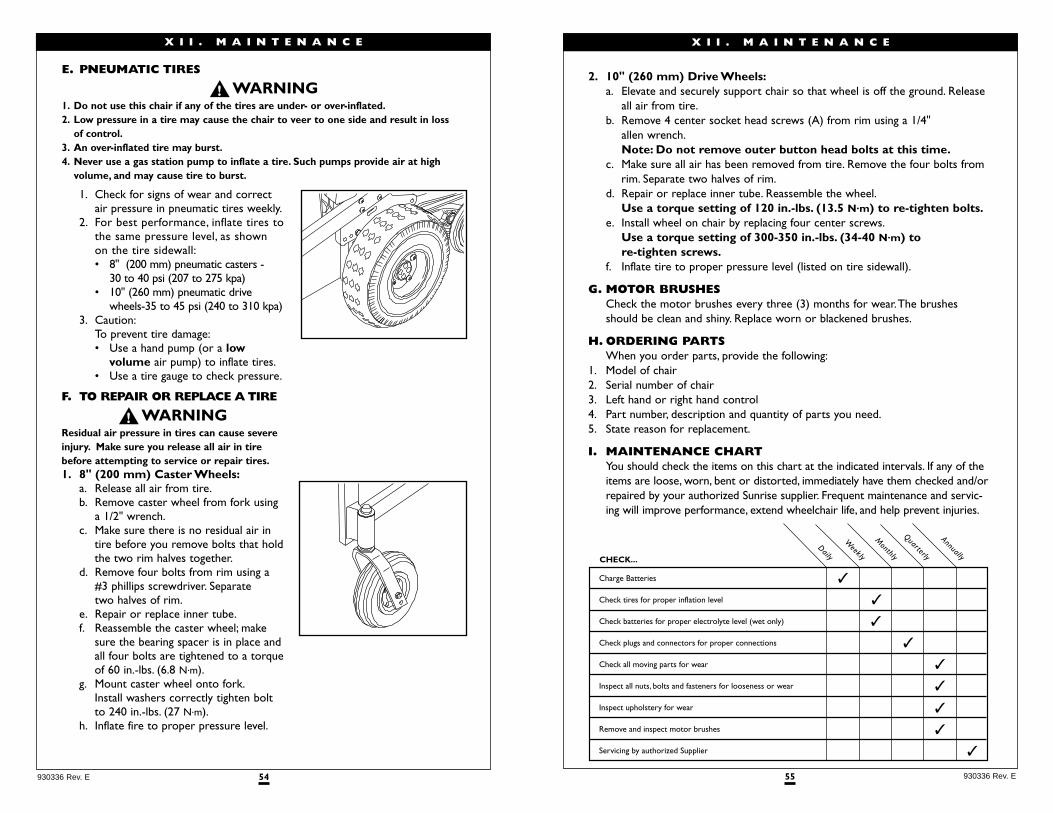
55 930336 Rev. E
X I I . M A I N T E N A N C E
2. 10" (260 mm) Drive Wheels:a. Elevate and securely support chair so that wheel is off the ground. Release
all air from tire.b. Remove 4 center socket head screws (A) from rim using a 1/4"
allen wrench.Note: Do not remove outer button head bolts at this time.
c. Make sure all air has been removed from tire. Remove the four bolts fromrim. Separate two halves of rim.
d. Repair or replace inner tube. Reassemble the wheel.Use a torque setting of 120 in.-lbs. (13.5 N.m) to re-tighten bolts.
e. Install wheel on chair by replacing four center screws.Use a torque setting of 300-350 in.-lbs. (34-40 N.m) to re-tighten screws.
f. Inflate tire to proper pressure level (listed on tire sidewall).
G. MOTOR BRUSHES Check the motor brushes every three (3) months for wear.The brushesshould be clean and shiny. Replace worn or blackened brushes.
H. ORDERING PARTS When you order parts, provide the following:
1. Model of chair2. Serial number of chair3. Left hand or right hand control4. Part number, description and quantity of parts you need.5. State reason for replacement.
I. MAINTENANCE CHARTYou should check the items on this chart at the indicated intervals. If any of theitems are loose, worn, bent or distorted, immediately have them checked and/orrepaired by your authorized Sunrise supplier. Frequent maintenance and servic-ing will improve performance, extend wheelchair life, and help prevent injuries.
Charge Batteries
Check tires for proper inflation level
Check batteries for proper electrolyte level (wet only)
Check plugs and connectors for proper connections
Check all moving parts for wear
Inspect all nuts, bolts and fasteners for looseness or wear
Inspect upholstery for wear
Remove and inspect motor brushes
Servicing by authorized Supplier
CHECK...
✓
✓
✓
✓
✓
✓
✓
✓
✓
Quarterly
Annually
Monthly
Weekly
Daily
54930336 Rev. E
1. Check for signs of wear and correct air pressure in pneumatic tires weekly.
2. For best performance, inflate tires to the same pressure level, as shown on the tire sidewall:• 8" (200 mm) pneumatic casters -
30 to 40 psi (207 to 275 kpa)• 10" (260 mm) pneumatic drive
wheels-35 to 45 psi (240 to 310 kpa)3. Caution:
To prevent tire damage:• Use a hand pump (or a low
volume air pump) to inflate tires.• Use a tire gauge to check pressure.
F. TO REPAIR OR REPLACE A TIRE
Residual air pressure in tires can cause severeinjury. Make sure you release all air in tirebefore attempting to service or repair tires.1. 8" (200 mm) Caster Wheels:
a. Release all air from tire.b. Remove caster wheel from fork using
a 1/2" wrench.c. Make sure there is no residual air in
tire before you remove bolts that holdthe two rim halves together.
d. Remove four bolts from rim using a #3 phillips screwdriver. Separate two halves of rim.
e. Repair or replace inner tube.f. Reassemble the caster wheel; make
sure the bearing spacer is in place andall four bolts are tightened to a torqueof 60 in.-lbs. (6.8 N.m).
g. Mount caster wheel onto fork.Install washers correctly tighten boltto 240 in.-lbs. (27 N.m).
h. Inflate fire to proper pressure level.
X I I . M A I N T E N A N C E
E. PNEUMATIC TIRES
1. Do not use this chair if any of the tires are under- or over-inflated.2. Low pressure in a tire may cause the chair to veer to one side and result in loss
of control.3. An over-inflated tire may burst.4. Never use a gas station pump to inflate a tire. Such pumps provide air at high
volume, and may cause tire to burst.
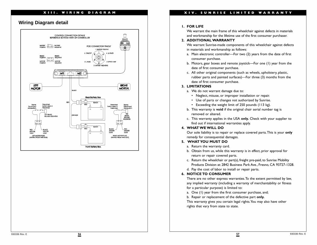
57 930336 Rev. E
X I V . S U N R I S E L I M I T E D W A R R A N T Y
1. FOR LIFEWe warrant the main frame of this wheelchair against defects in materialsand workmanship for the lifetime use of the first consumer purchaser.
2. ADDITIONAL WARRANTYWe warrant Sunrise-made components of this wheelchair against defectsin materials and workmanship as follows:a. Main electronic controller—For two (2) years from the date of first
consumer purchase.b. Motors, gear boxes and remote joystick—For one (1) year from the
date of first consumer purchase.c. All other original components (such as wheels, upholstery, plastic,
rubber parts and painted surfaces)—For three (3) months from thedate of first consumer purchase.
3. LIMITATIONSa. We do not warrant damage due to:
• Neglect, misuse, or improper installation or repair.• Use of parts or changes not authorized by Sunrise.• Exceeding the weight limit of 250 pounds (113 kg).
b. This warranty is void if the original chair serial number tag isremoved or altered.
c. This warranty applies in the USA only. Check with your supplier tofind out if international warranties apply.
4. WHAT WE WILL DOOur sole liability is to repair or replace covered parts.This is your onlyremedy for consequential damages.
5. WHAT YOU MUST DOa. Return the warranty card.b. Obtain from us, while this warranty is in effect, prior approval for
return or repair covered parts.c. Return the wheelchair or part(s), freight pre-paid, to Sunrise Mobility
Products Division at: 2842 Business Park Ave., Fresno, CA 93727-1328.d. Pay the cost of labor to install or repair parts.
6. NOTICE TO CONSUMERThere are no other express warranties.To the extent permitted by law,any implied warranty (including a warranty of merchantability or fitnessfor a particular purpose) is limited to:a. One (1) year from the first consumer purchase, and;b. Repair or replacement of the defective part only.This warranty gives you certain legal rights.You may also have otherrights that vary from state to state.
56930336 Rev. E
X I I I . W I R I N G D I A G R A M
Wiring Diagram detail

58930336 Rev. E
N O T E S

Sunrise Home Healthcare Group Mobility Products Division
7477 East Dry Creek Parkway • Longmont, Colorado • 80503 USA
(800) 333-4000
In Canada (800) 263-3390
Manufactured under one or more of the following patents:
U.S. Patent # 5,062,677; 5,149,173; 5,211,446; 5,352,023; 5,407,248; plus other foreign patents.
© 1999, Sunrise Medical 5.99930336 Rev. E