Embed Size (px)
Citation preview
POLYMER80 Page 1
POLYMER80
WarrHogg 308 AR 80% Lower Receiver Instructions Author: Loran Kelley, Polymer80 Co-Founder
Warrhogg 308 AR
Contents
Warnings!! – Issues that impact warranty coverage!! .............................................................................................................. 2
Parts List ................................................................................................................................................................................. 2
Methods to Finish the Lower Receiver: .................................................................................................................................... 2
Example Tools ......................................................................................................................................................................... 3
Jig Hole Descriptions & Purpose .............................................................................................................................................. 4
Getting Familiar with the Jig and Lower Receiver ..................................................................................................................... 4
The Features and Description of the Jig ............................................................................................................................. 4
The Features and Description of the Lower Receiver .......................................................................................................... 6
Procedure: .............................................................................................................................................................................. 8
Final checks and misc notes:.................................................................................................................................................. 11
POLYMER80 Page 2
Warnings!! – Issues that impact warranty coverage!! Polymer80, Inc. stands by our product and offers an excellent no-hassle warranty coverage. But, there are limits to
coverage, particularly when the customer damages the product through poor craftsmanship or control during the milling process. Additionally, after the milling is completed, the build process seems to be where most people get into trouble, particularly during assembly and cleaning. Here are key areas that you need to watch for:
1. Do not use any lock-tight on the receiver – regardless of what some internet assembly instructions tell you. 2. Chemicals: Generally, you do not need to lubricate polymer products.
a. Many oils are combined with rust penetrants which can damage polymer based products. b. Do not utilize brake cleaner or rust penetrants, they penetrate through polymer, similar to how they
penetrate into metal. c. Do not put Acetone on the receiver. Acetone will generally instantly destroy, mar, or weaken any
polymer-based product.
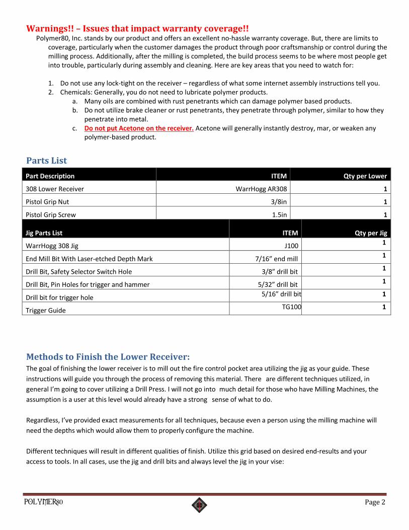
Parts List
Part Description ITEM Qty per Lower
308 Lower Receiver WarrHogg AR308 1
Pistol Grip Nut 3/8in 1
Pistol Grip Screw 1.5in 1
Jig Parts List
ITEM
Qty per Jig
WarrHogg 308 Jig J100 1
End Mill Bit With Laser-etched Depth Mark 7/16” end mill 1
Drill Bit, Safety Selector Switch Hole 3/8” drill bit 1
Drill Bit, Pin Holes for trigger and hammer 5/32” drill bit 1
Drill bit for trigger hole 5/16” drill bit 1
Trigger Guide TG100 1
Methods to Finish the Lower Receiver: The goal of finishing the lower receiver is to mill out the fire control pocket area utilizing the jig as your guide. These
instructions will guide you through the process of removing this material. There are different techniques utilized, in
general I’m going to cover utilizing a Drill Press. I will not go into much detail for those who have Milling Machines, the
assumption is a user at this level would already have a strong sense of what to do.
Regardless, I’ve provided exact measurements for all techniques, because even a person using the milling machine will
need the depths which would allow them to properly configure the machine.
Different techniques will result in different qualities of finish. Utilize this grid based on desired end-results and your
access to tools. In all cases, use the jig and drill bits and always level the jig in your vise:
POLYMER80 Page 3
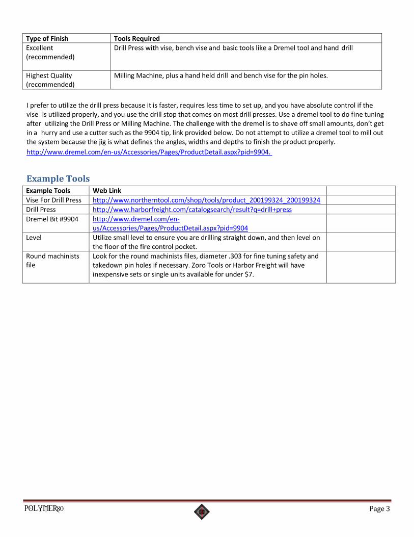
Type of Finish Tools Required Excellent (recommended)
Drill Press with vise, bench vise and basic tools like a Dremel tool and hand drill
Highest Quality (recommended)
Milling Machine, plus a hand held drill and bench vise for the pin holes.
I prefer to utilize the drill press because it is faster, requires less time to set up, and you have absolute control if the vise is utilized properly, and you use the drill stop that comes on most drill presses. Use a dremel tool to do fine tuning after utilizing the Drill Press or Milling Machine. The challenge with the dremel is to shave off small amounts, don’t get in a hurry and use a cutter such as the 9904 tip, link provided below. Do not attempt to utilize a dremel tool to mill out the system because the jig is what defines the angles, widths and depths to finish the product properly.
http://www.dremel.com/en-us/Accessories/Pages/ProductDetail.aspx?pid=9904.
Example Tools
Example Tools Web Link
Vise For Drill Press http://www.northerntool.com/shop/tools/product_200199324_200199324
Drill Press http://www.harborfreight.com/catalogsearch/result?q=drill+press
Dremel Bit #9904 http://www.dremel.com/en- us/Accessories/Pages/ProductDetail.aspx?pid=9904
Level Utilize small level to ensure you are drilling straight down, and then level on the floor of the fire control pocket.
Round machinists file
Look for the round machinists files, diameter .303 for fine tuning safety and takedown pin holes if necessary. Zoro Tools or Harbor Freight will have inexpensive sets or single units available for under $7.
POLYMER80 Page 4
Jig Hole Descriptions & Purpose
Jig Hole Function Depth from top of Jig to floor of Fire Control Pocket
Depth from top of Receiver to floor of Fire Control Pocket
Hole #1 Mills out the upper platform section that divides the fire control pocket from the rear take down pin area.
44.5mm (use the floor of the rear take down pin area as the guide)
Hole #2 This hole opens up a pocket for the rear side of the trigger mechanism. This hole is the trickiest, do not penetrate into the right side where there’s a slight protrusion of the polycarbonate material. The safety selector switch detent pin goes in this area.
44.5mm 1.25in exact
Hole #3 The back side of the fire control pocket 44.5mm 1.25in exact
Hole #4 The front side of the fire control pocket, closest to the magazine well.
44.5mm 1.25in exact
Trigger Hole
Drilling this hole opens up the trigger hole. This is one of the first steps using the 5/16ths drill bit.
Drilled through holes
Drilled through holes
Note how the jig with the End Mill bit set at 44.5mm creates a consistent drilling depth. Just move the drill press table
up or down to position properly as you move from holes 1&2 to the Fire Control Pocket.
Many hardware stores have fairly inexpensive drill presses (Lowes, Home Depot, Harbor Freight, Granger, etc.).
Getting Familiar with the Jig and Lower Receiver
The goal of finishing the lower receiver is to mill out the fire control pocket of the receiver to the proper depth, and to
utilize the jig to get correct placement on the side holes (trigger, hammer and safety holes). The solid core fills the
entire fire control pocket.
It’s important to note the features of the jig and the lower before you start working on the unit.
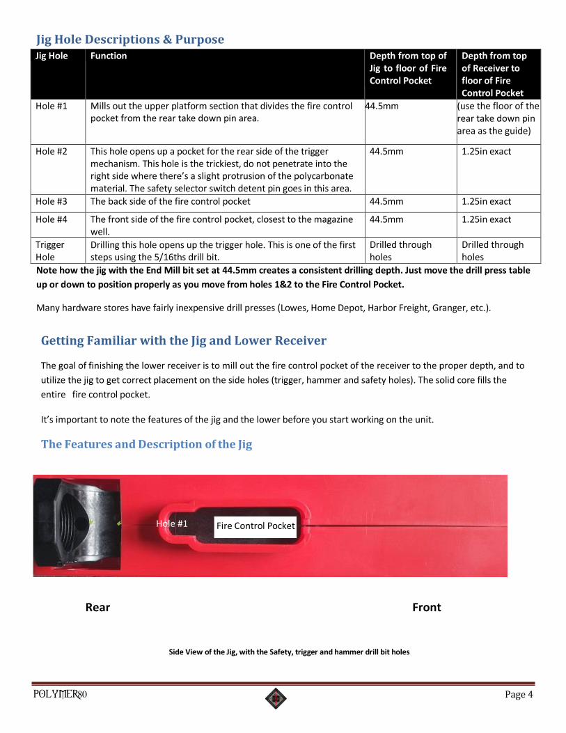
The Features and Description of the Jig
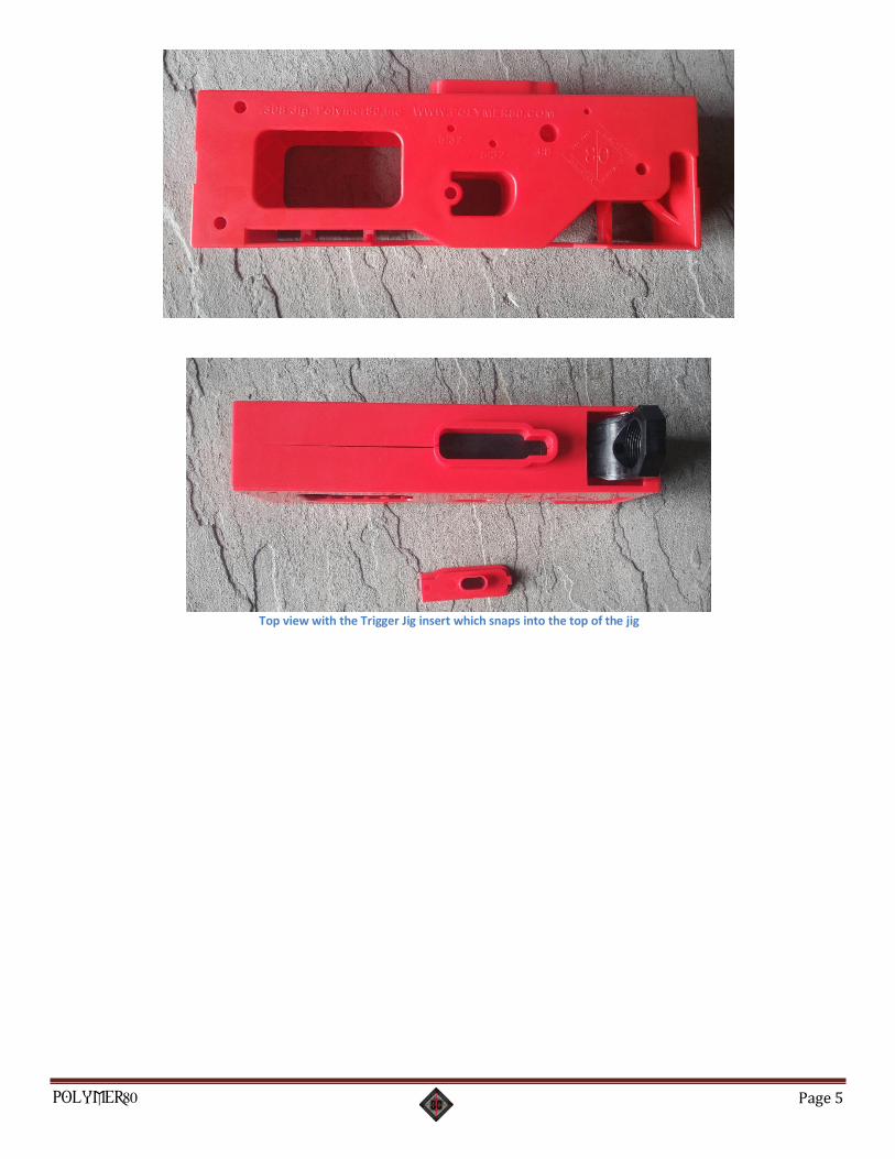
Side View of the Jig, with the Safety, trigger and hammer drill bit holes
Hole #1 Fire Control Pocket
Rear Front
POLYMER80 Page 5
Top view with the Trigger Jig insert which snaps into the top of the jig
POLYMER80 Page 6
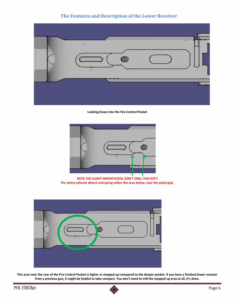
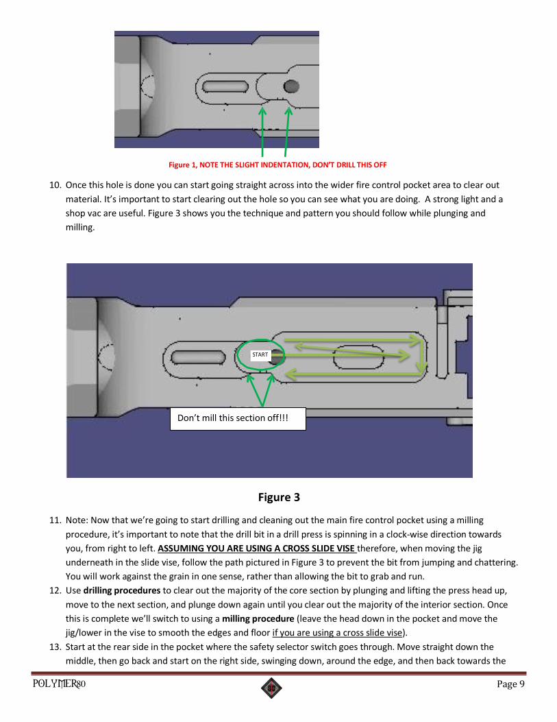
The Features and Description of the Lower Receiver
Looking Down into the Fire Control Pocket
NOTE THE SLIGHT INDENTATION, DON’T DRILL THIS OFF!!
The safety selector detent and spring utilize this area below, near the pistol grip.
This area near the rear of the Fire Control Pocket is higher or stepped up compared to the deeper pocket. If you have a finished lower receiver from a previous gun, it might be helpful to take compare. You don’t need to mill the stepped up area at all, it’s done.
POLYMER80 Page 7
Preparation (Assumes you are using a Drill Press)
1. Prep the drill press. When using a drill press, the spinning head of the drill press needs to be firmly attached by
slamming it with a mallet up into the press, or the vibration of the below procedure can sometimes make the
entire head fall out (spinning and ruining things in the process). Take any drill bits out, get a mallet and hit
upwards to securely implant the head.
2. Level: Must have a level to create a level interior fire control pocket
3. The end mill slide vise on the drill press (a link is provided above) is the absolute fastest and most secure way to
finish this part. Using a tool like this as opposed to just using a dremel tool, you’re going to be done much
sooner with outstanding results. We utilize the slide vise in various ways around the shop, it’s great tool that can
be mounted on the drill press table directly, or on your bench underneath a smaller bench drill press and utilized
for many other projects.
4. Final Mental Prep: Building a firearm takes craftsmanship and pride, so don’t be in a hurry! Slow down and work
precisely and methodically Measuring Twice and Cutting Once!! After you drill something out, you can’t put it
back, so approach things conservatively. In my personal experience, if I’m feeling like I have no patience, I just
stop. I’ll put the tools down and walk away from the bench and go take care of whatever made me be in a hurry
in the first place. Sounds sort of simple, but I’ve destroyed too many things in the past from my lack of patience,
and if you do it on this part it’s going to cost much more time and money (and yes, I have ruined some lowers).
Again, YOU NEED TO SET THE DRILL PRESS DEPTH PROPERLY. The end mill bit is marked at 44.5mm with a black line.
Don’t rely on the drill press depth stop 100%, utilize the drill stop while also watching the black line on the end mill bit
to make sure you don’t go too deep. “Measure twice, cut once!” In other words, keep checking the depth at every
drill point.
POLYMER80 Page 8
Procedure: 1. Put the Lower Receiver in the Jig and snap them together. Set the small red trigger guide aside for the moment.
2. Make sure that the front and rear snap clips are firmly closed
3. The first step is to drill the side pin holes (Hammer, Trigger and Safety Selector Switch Hole) using the lower
receiver in the Jig. Drill a ¼ inch into each side, BUT NOT ALL THE WAY THROUGH.
• Put the jig & lower in a regular vise on your bench, select the proper bits provided and drill on one
side only, then flip the jig and drill the holes on the opposite side.
• DON’T try to drill through both sides at one time, GUARANTEED THE BIT WILL DRIFT AND MISS
THE TARGET ON THE OTHER END!!
• These holes have to be exact. Start the drill full speed with the proper drill bit sizes designated on
the side of the Jig, push it into the hole steady and level, drill into the black material only a 1/4” to
get the hole through the side wall. Later, once you finish the interior pocket mill-out, the holes will
have already been completed.
4. (Optional) On the drill press with the Jig and Lower tightly installed on the vise, install the large regular drill bit
used for the safety selector switch holes to create a pilot hole in the fire control pocket area. Don’t drill too
deep, just get a hole that goes down and do not penetrate beyond 40mm from the top of the jig to be safe. This
hole will help once you start using the End Mill Bit.
5. Once a pilot hole is drilled, insert the End Mill Bit on the drill press, adjust TABLE of the drill press so that the tip
of the bit is exactly even with the top of the jig (bend down and look closely, sometimes as you tighten the drill
press table, the table drifts up). Adjust the bit so it is hovering out over the center of the fire control pocket
where your PILOT HOLE was drilled. In other words, don’t start drilling at Hole #1 that is identified in the above
pictures. The table that the vise is on or attached to must also be tightened (example: The drill press TABLE must
be tightened on the back tightening knob or they can move. Crank it down hard!! The material used to create
the lower is extremely tough. Therefore while using an End Mill Bit, it will create lots of tension and vibration if
things aren’t tight – YOU’VE BEEN WARNED!
6. Adjust the drill press stop to 44.5mm. Notice that the end mill bit also has a black mark that indicates 44.5mm
depth
7. Now start drilling down slowly through the pilot hole taking just small sections of material off slowly. Go down
exactly 44.5mm down watching the top of the jig and end mill bit. Don’t allow the black line on the end mill bit
to go below the top of the jig. During each and every drill procedure visually checking to make sure the bit is
not sliding up or down within the drill press chuck. Again, the bit starting position is dead even with the top of
the jig, as you plunge watch the black line on the bit, not allowing it to go deeper than the top of the jig.
8. If you have a vise that allows X and Y axis movement, (like a drill press slide vise pictured in the link above) take
advantage of the End Mill Bit and clean out the pocket floor and sides slowly moving along the edge to create a
smooth side wall on both sides.
9. Hole #1 Drilling Procedure and Warnings - Figure 1: Before we get started on Hole Number 1 area, there’s one
important feature that you must pay attention to. There’s a slight but IMPORTANT indentation that you can’t
drill through because the safety selector DETENT hole is drilled through this area underneath the lower (near
the pistol grip).
POLYMER80 Page 9
Figure 1, NOTE THE SLIGHT INDENTATION, DON’T DRILL THIS OFF
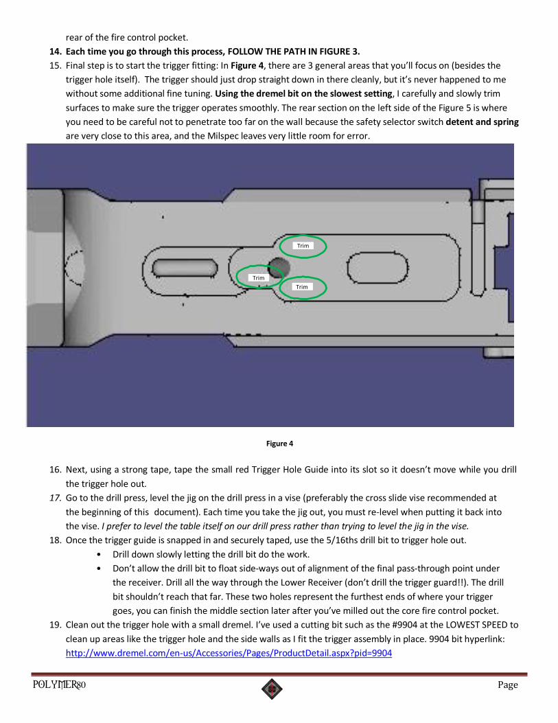
10. Once this hole is done you can start going straight across into the wider fire control pocket area to clear out
material. It’s important to start clearing out the hole so you can see what you are doing. A strong light and a
shop vac are useful. Figure 3 shows you the technique and pattern you should follow while plunging and
milling.
Figure 3
11. Note: Now that we’re going to start drilling and cleaning out the main fire control pocket using a milling
procedure, it’s important to note that the drill bit in a drill press is spinning in a clock-wise direction towards
you, from right to left. ASSUMING YOU ARE USING A CROSS SLIDE VISE therefore, when moving the jig
underneath in the slide vise, follow the path pictured in Figure 3 to prevent the bit from jumping and chattering.
You will work against the grain in one sense, rather than allowing the bit to grab and run.
12. Use drilling procedures to clear out the majority of the core section by plunging and lifting the press head up,
move to the next section, and plunge down again until you clear out the majority of the interior section. Once
this is complete we’ll switch to using a milling procedure (leave the head down in the pocket and move the
jig/lower in the vise to smooth the edges and floor if you are using a cross slide vise).
13. Start at the rear side in the pocket where the safety selector switch goes through. Move straight down the
middle, then go back and start on the right side, swinging down, around the edge, and then back towards the
Don’t mill this section off!!!
POLYMER80 Page 10
rear of the fire control pocket.
14. Each time you go through this process, FOLLOW THE PATH IN FIGURE 3.
15. Final step is to start the trigger fitting: In Figure 4, there are 3 general areas that you’ll focus on (besides the
trigger hole itself). The trigger should just drop straight down in there cleanly, but it’s never happened to me
without some additional fine tuning. Using the dremel bit on the slowest setting, I carefully and slowly trim
surfaces to make sure the trigger operates smoothly. The rear section on the left side of the Figure 5 is where
you need to be careful not to penetrate too far on the wall because the safety selector switch detent and spring
are very close to this area, and the Milspec leaves very little room for error.
Figure 4
16. Next, using a strong tape, tape the small red Trigger Hole Guide into its slot so it doesn’t move while you drill
the trigger hole out.
17. Go to the drill press, level the jig on the drill press in a vise (preferably the cross slide vise recommended at
the beginning of this document). Each time you take the jig out, you must re-level when putting it back into
the vise. I prefer to level the table itself on our drill press rather than trying to level the jig in the vise.
18. Once the trigger guide is snapped in and securely taped, use the 5/16ths drill bit to trigger hole out.
• Drill down slowly letting the drill bit do the work.
• Don’t allow the drill bit to float side-ways out of alignment of the final pass-through point under
the receiver. Drill all the way through the Lower Receiver (don’t drill the trigger guard!!). The drill
bit shouldn’t reach that far. These two holes represent the furthest ends of where your trigger
goes, you can finish the middle section later after you’ve milled out the core fire control pocket.
19. Clean out the trigger hole with a small dremel. I’ve used a cutting bit such as the #9904 at the LOWEST SPEED to
clean up areas like the trigger hole and the side walls as I fit the trigger assembly in place. 9904 bit hyperlink:
http://www.dremel.com/en-us/Accessories/Pages/ProductDetail.aspx?pid=9904
Trim
Trim
Trim

POLYMER80 Page 11
Final checks and misc notes:
1. The depth of the fire control pocket should be 1.25 inches from top of receiver…precise.
2. If you have a ton of trouble getting the trigger in because the pin holes aren’t aligning, you might consider
several inspections, modifications, or troubleshooting in the following order:
1. Make sure the trigger hole is vacated of any material that prevents proper movement.
2. Make sure the rear of the trigger is not rubbing against that odd offset wall that houses the safety
selector switch detent.
3. Taking a very slight amount more off of the floor of the fire control pocket with the end mill bit (go back
to the vise and make sure the jig/lower is level and just take several hundredth’s of an inch off then go
back to the trigger fitting to see if that helps.
3. At the front side of the fire control pocket, there’s very little room in the original milspec design between what I
term the firewall and the mag release button housing. If you see exposure to that area after you drill, don’t be
alarmed, there’s almost no material there by milspec design, but this will not impact performance of the
firearm. Even on aluminum 80% receivers, it’s common to shave off an amount that allows you to see through
into the mag release button area.
4. After you install the trigger and hammer, the trigger should release the hammer properly and cleanly of course. 5. Further instructions on how to assemble the lower parts kit that has the trigger and hammer are found here:
http://www.polymer80.com/info
Any further questions, feel free to email us at our support email address or call:
800-517-1243 [email protected]


![Chapter 308-93 WAC - Legislature Homeleg.wa.gov/CodeReviser/WACArchive/Documents/2012/WAC-308-93... · (5/11/10) [Ch. 308-93 WAC—p. 1] Chapter 308-93 Chapter 308-93 WAC VESSEL REGISTRATION](https://img.pdfslide.net/doc/110x75/5b99bc9a09d3f29c338cd7cb/chapter-308-93-wac-legislature-51110-ch-308-93-wacp-1-chapter-308-93.jpg)