Embed Size (px)
Citation preview

Multiprogrammable Pacemakers S201, S203, S204, S205, S206, S208, S209
ALTRUA™20SYSTEM GUIDE

ABOUT THIS MANUALBoston Scientific Corporation acquired Guidant Corporation in April 2006. During our transition period, you may see both the Boston Scientific and Guidant names on product and patient materials. As we work through the transition, we will continue to offer doctors and their patients technologically advanced and high quality medical devices and therapies.
This pacemaker system guide can be used with all ALTRUA™ 20 pacing systems. These pacemakers are used with the Model 2892 CONSULT Software Application and the ZOOM™ LATITUDE™ Programming System, which includes the Model 3120 Programmer/Recorder/Monitor (PRM). Refer to the PRM Operator’s Manual for full instructions.
Manual ConventionsThroughout this manual, the following text conventions will be used:
PRM KEYS The names of the PRM keys will appear in capital letters (e.g., PROGRAM, INTERROGATE).
Screen Text When text appearing on the PRM screen is referred to in the manual, it will appear with the first letter of each word capitalized.
1., 2., 3. Numbered lists indicate a series of instructions that should be followed in the order given.
Bullets precede items in a list, or a series that is not sequential.
A pacemaker profile appears in the margin if the feature being discussed applies only to a specific type of pacemaker (e.g., DR). If the feature applies to all models, there will be no profile.
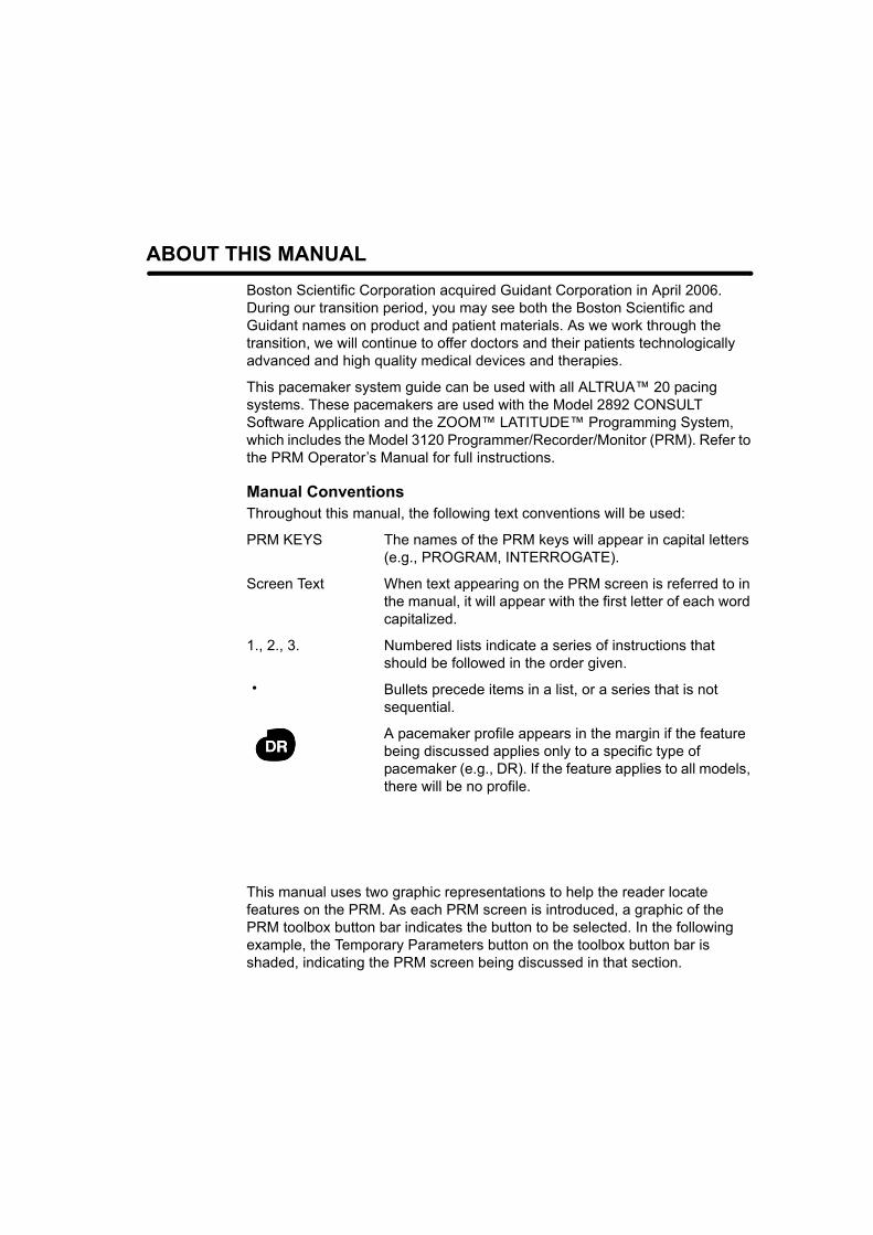
This manual uses two graphic representations to help the reader locate features on the PRM. As each PRM screen is introduced, a graphic of the PRM toolbox button bar indicates the button to be selected. In the following example, the Temporary Parameters button on the toolbox button bar is shaded, indicating the PRM screen being discussed in that section.
•
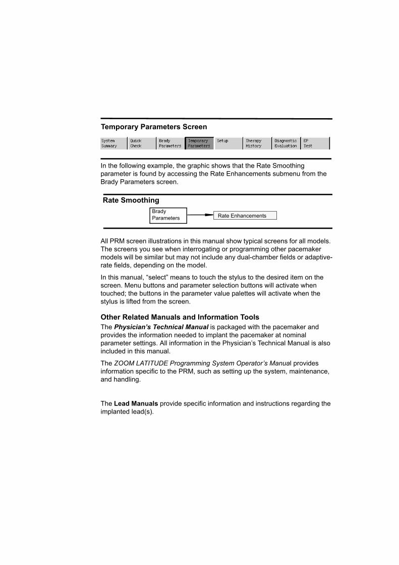
In the following example, the graphic shows that the Rate Smoothing parameter is found by accessing the Rate Enhancements submenu from the Brady Parameters screen.
All PRM screen illustrations in this manual show typical screens for all models. The screens you see when interrogating or programming other pacemaker models will be similar but may not include any dual-chamber fields or adaptive-rate fields, depending on the model.
In this manual, “select” means to touch the stylus to the desired item on the screen. Menu buttons and parameter selection buttons will activate when touched; the buttons in the parameter value palettes will activate when the stylus is lifted from the screen.
Other Related Manuals and Information ToolsThe Physician’s Technical Manual is packaged with the pacemaker and provides the information needed to implant the pacemaker at nominal parameter settings. All information in the Physician’s Technical Manual is also included in this manual.
The ZOOM LATITUDE Programming System Operator’s Manual provides information specific to the PRM, such as setting up the system, maintenance, and handling.
The Lead Manuals provide specific information and instructions regarding the implanted lead(s).
Temporary Parameters Screen
Rate SmoothingBrady Parameters Rate Enhancements
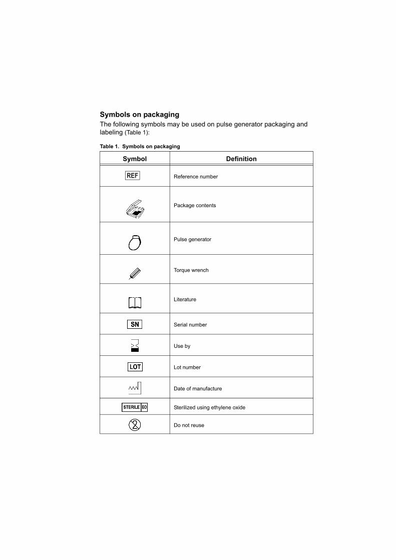
Symbols on packagingThe following symbols may be used on pulse generator packaging and labeling (Table 1):
Table 1. Symbols on packaging
Symbol Definition
Reference number
Package contents
Pulse generator
Torque wrench
Literature
Serial number
Use by
Lot number
Date of manufacture
Sterilized using ethylene oxide
Do not reuse

The following trademarks are property of Boston Scientific or its affiliates: ALTRUA, LATITUDE, Quick Notes, Quick Start, and ZOOM.
Consult instructions for use
Temperature limitation
Wand placement indicator
Opening instructions
CE mark of conformity with the identification of the notified body authorizing use of the mark
Manufacturer
Authorized Representative in the European Community
Do not resterilize
Do not use if package is damaged
Australian sponsor address
Table 1. Symbols on packaging
Symbol Definition

TABLE OF CONTENTS
REFERENCE TABLES ........................................................................................................... INominal Mechanical Specifications..................................................................................... iX-ray Identifier..................................................................................................................... iALTRUA 20 Longevity Projections Years .......................................................................... iiMagnet Test and Battery Operation ................................................................................... iiiFeatures List ...................................................................................................................... iii
INFORMATION FOR USE ..................................................................................................1-1CHAPTER 1
Device Description ..........................................................................................................1-2Indications and Usage .....................................................................................................1-2Contraindications ............................................................................................................1-3Warnings and Precautions ..............................................................................................1-3
Clinical Considerations............................................................................................... 1-3Sterilization, Storage, and Handling ........................................................................... 1-4Lead Evaluation and Connection ............................................................................... 1-5Implantation................................................................................................................ 1-5Programming and Pacemaker Operation................................................................... 1-6Environmental and Medical Therapy Hazards ........................................................... 1-6Elevated Pressure .................................................................................................... 1-11Explanted Pacemakers ............................................................................................ 1-13
Adverse Events .............................................................................................................1-13Product Reliability .........................................................................................................1-14Patient Counseling Information .....................................................................................1-15
Patient Handbook..................................................................................................... 1-15Patient Identification (ID) Card ................................................................................. 1-15
PRE-IMPLANT AND IMPLANT INFORMATION ................................................................2-1CHAPTER 2
Storage ............................................................................................................................2-2Opening Instructions .......................................................................................................2-2Items Included .................................................................................................................2-3Sterilization ......................................................................................................................2-3Lead Connections ...........................................................................................................2-3
Lead Adapters ............................................................................................................ 2-4Lead-to-Pacemaker Connection................................................................................. 2-5
Pacemaker Insertion .......................................................................................................2-8Automatic Lead Implant Detection ............................................................................. 2-8Pacemaker Insertion Procedure................................................................................. 2-9
TECHNICAL INFORMATION ..............................................................................................3-1CHAPTER 3
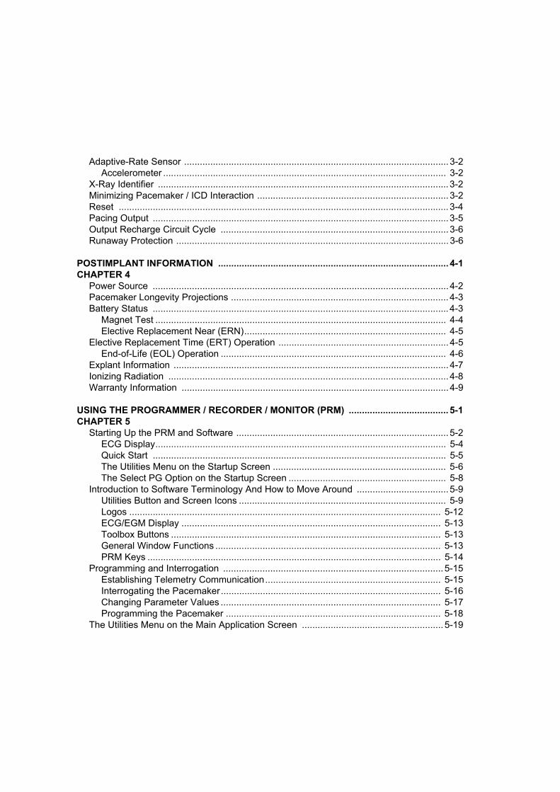
Adaptive-Rate Sensor ..................................................................................................... 3-2Accelerometer ............................................................................................................ 3-2
X-Ray Identifier ............................................................................................................... 3-2Minimizing Pacemaker / ICD Interaction ......................................................................... 3-2Reset .............................................................................................................................. 3-4Pacing Output .................................................................................................................3-5Output Recharge Circuit Cycle ....................................................................................... 3-6Runaway Protection ........................................................................................................ 3-6
POSTIMPLANT INFORMATION ........................................................................................ 4-1CHAPTER 4
Power Source ................................................................................................................. 4-2Pacemaker Longevity Projections ................................................................................... 4-3Battery Status ................................................................................................................. 4-3
Magnet Test ............................................................................................................... 4-4Elective Replacement Near (ERN)............................................................................. 4-5
Elective Replacement Time (ERT) Operation ................................................................. 4-5End-of-Life (EOL) Operation ...................................................................................... 4-6
Explant Information ......................................................................................................... 4-7Ionizing Radiation ........................................................................................................... 4-8Warranty Information ...................................................................................................... 4-9
USING THE PROGRAMMER / RECORDER / MONITOR (PRM) ...................................... 5-1CHAPTER 5
Starting Up the PRM and Software ................................................................................. 5-2ECG Display............................................................................................................... 5-4Quick Start ................................................................................................................ 5-5The Utilities Menu on the Startup Screen .................................................................. 5-6The Select PG Option on the Startup Screen ............................................................ 5-8
Introduction to Software Terminology And How to Move Around ................................... 5-9Utilities Button and Screen Icons ............................................................................... 5-9Logos ....................................................................................................................... 5-12ECG/EGM Display ................................................................................................... 5-13Toolbox Buttons ....................................................................................................... 5-13General Window Functions ...................................................................................... 5-13PRM Keys ................................................................................................................ 5-14
Programming and Interrogation .................................................................................... 5-15Establishing Telemetry Communication................................................................... 5-15Interrogating the Pacemaker.................................................................................... 5-16Changing Parameter Values .................................................................................... 5-17Programming the Pacemaker .................................................................................. 5-18
The Utilities Menu on the Main Application Screen ...................................................... 5-19

Patient Data ............................................................................................................. 5-19Save All to Disk........................................................................................................ 5-20Copy Disk ................................................................................................................ 5-21Format Disk ............................................................................................................. 5-21The Set Programmer Clock Utility ........................................................................... 5-22About ....................................................................................................................... 5-22Print Memory ........................................................................................................... 5-22New Patient ............................................................................................................. 5-23Quit .......................................................................................................................... 5-23
THERAPY ........................................................................................................................... 6-1CHAPTER 6
Brady Parameters Screen .............................................................................................. 6-2Brady Parameters Submenus.................................................................................... 6-2Modifying Parameter Values...................................................................................... 6-3The Cancel Changes Button...................................................................................... 6-3The Load Nominals Button ........................................................................................ 6-3The Load Initial Values Button................................................................................... 6-4
Mode .............................................................................................................................. 6-5A-Tachy Response ......................................................................................................... 6-7Lower Rate Limit (LRL) .................................................................................................. 6-7Max Tracking Rate (MTR) .............................................................................................. 6-8
Conventional DDD Behavior...................................................................................... 6-8Max Sensor Rate .......................................................................................................... 6-10AV Delay (paced) ......................................................................................................... 6-11Pulse Width .................................................................................................................. 6-11Amplitude ..................................................................................................................... 6-12Sensitivity ..................................................................................................................... 6-13Refractory Periods ........................................................................................................ 6-13
Atrial Refractory Period............................................................................................ 6-14Post-Ventricular Atrial Refractory Period (PVARP) ................................................. 6-14Ventricular Refractory Period................................................................................... 6-14
Pace/Sense .................................................................................................................. 6-15Adaptive-Rate Pacing ................................................................................................... 6-16Accelerometer .............................................................................................................. 6-16
Response Factor (Accelerometer)........................................................................... 6-17Advanced Accelerometer Parameters ..................................................................... 6-19
A-Tachy Response (ATR) ............................................................................................ 6-24Trigger Rate............................................................................................................. 6-24Entry Count.............................................................................................................. 6-25Exit Count ................................................................................................................ 6-25Duration ................................................................................................................... 6-26
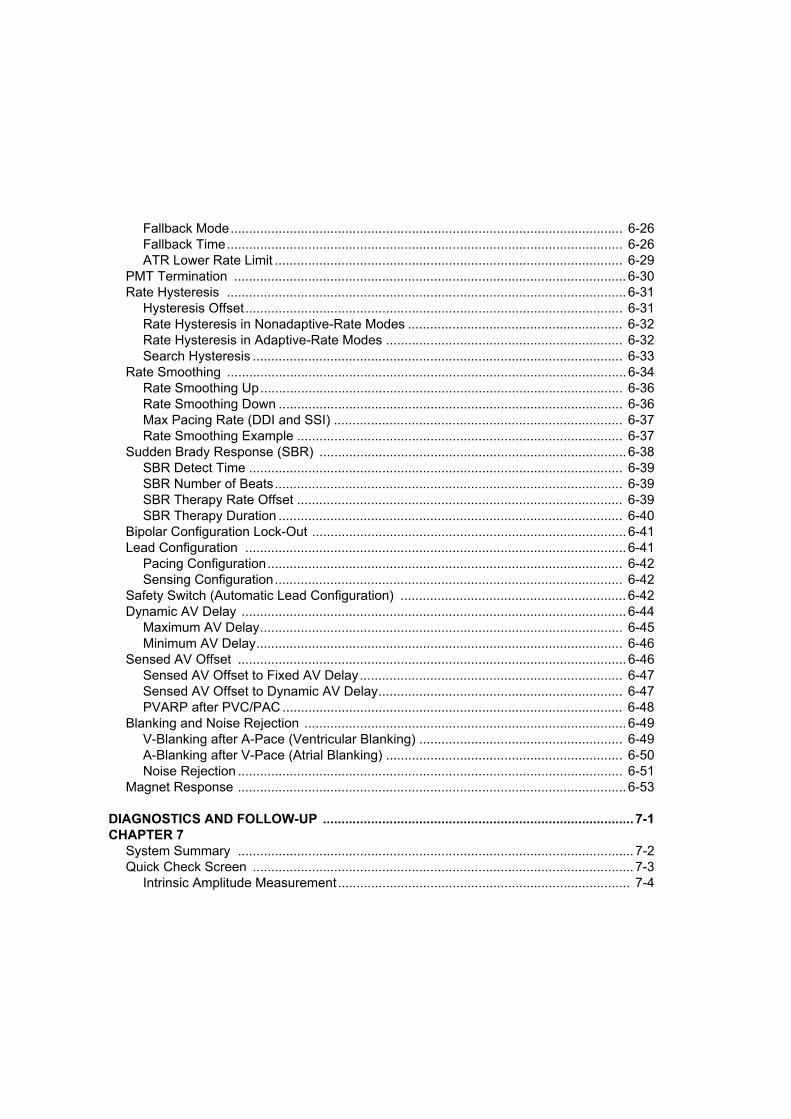
Fallback Mode.......................................................................................................... 6-26Fallback Time........................................................................................................... 6-26ATR Lower Rate Limit .............................................................................................. 6-29
PMT Termination .......................................................................................................... 6-30Rate Hysteresis ............................................................................................................ 6-31
Hysteresis Offset...................................................................................................... 6-31Rate Hysteresis in Nonadaptive-Rate Modes .......................................................... 6-32Rate Hysteresis in Adaptive-Rate Modes ................................................................ 6-32Search Hysteresis .................................................................................................... 6-33
Rate Smoothing ............................................................................................................ 6-34Rate Smoothing Up.................................................................................................. 6-36Rate Smoothing Down ............................................................................................. 6-36Max Pacing Rate (DDI and SSI) .............................................................................. 6-37Rate Smoothing Example ........................................................................................ 6-37
Sudden Brady Response (SBR) ................................................................................... 6-38SBR Detect Time ..................................................................................................... 6-39SBR Number of Beats.............................................................................................. 6-39SBR Therapy Rate Offset ........................................................................................ 6-39SBR Therapy Duration ............................................................................................. 6-40
Bipolar Configuration Lock-Out ..................................................................................... 6-41Lead Configuration ....................................................................................................... 6-41
Pacing Configuration................................................................................................ 6-42Sensing Configuration.............................................................................................. 6-42
Safety Switch (Automatic Lead Configuration) ............................................................. 6-42Dynamic AV Delay ........................................................................................................ 6-44
Maximum AV Delay.................................................................................................. 6-45Minimum AV Delay................................................................................................... 6-46
Sensed AV Offset ......................................................................................................... 6-46Sensed AV Offset to Fixed AV Delay....................................................................... 6-47Sensed AV Offset to Dynamic AV Delay.................................................................. 6-47PVARP after PVC/PAC ............................................................................................ 6-48
Blanking and Noise Rejection ....................................................................................... 6-49V-Blanking after A-Pace (Ventricular Blanking) ....................................................... 6-49A-Blanking after V-Pace (Atrial Blanking) ................................................................ 6-50Noise Rejection ........................................................................................................ 6-51
Magnet Response ......................................................................................................... 6-53
DIAGNOSTICS AND FOLLOW-UP .................................................................................... 7-1CHAPTER 7
System Summary ........................................................................................................... 7-2Quick Check Screen ....................................................................................................... 7-3
Intrinsic Amplitude Measurement............................................................................... 7-4
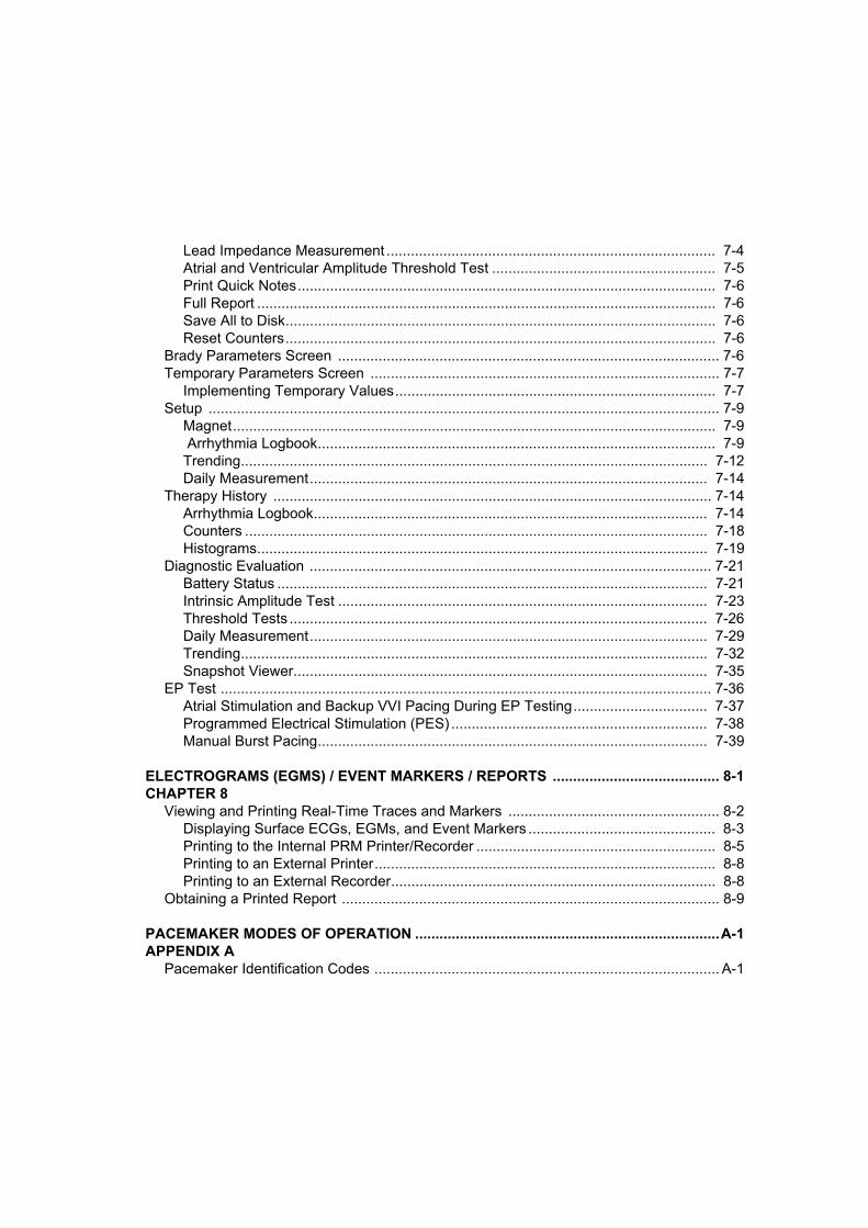
Lead Impedance Measurement ................................................................................. 7-4Atrial and Ventricular Amplitude Threshold Test ....................................................... 7-5Print Quick Notes....................................................................................................... 7-6Full Report ................................................................................................................. 7-6Save All to Disk.......................................................................................................... 7-6Reset Counters.......................................................................................................... 7-6
Brady Parameters Screen .............................................................................................. 7-6Temporary Parameters Screen ...................................................................................... 7-7
Implementing Temporary Values............................................................................... 7-7Setup .............................................................................................................................. 7-9
Magnet....................................................................................................................... 7-9 Arrhythmia Logbook.................................................................................................. 7-9Trending................................................................................................................... 7-12Daily Measurement.................................................................................................. 7-14
Therapy History ............................................................................................................ 7-14Arrhythmia Logbook................................................................................................. 7-14Counters .................................................................................................................. 7-18Histograms............................................................................................................... 7-19
Diagnostic Evaluation ................................................................................................... 7-21Battery Status .......................................................................................................... 7-21Intrinsic Amplitude Test ........................................................................................... 7-23Threshold Tests ....................................................................................................... 7-26Daily Measurement.................................................................................................. 7-29Trending................................................................................................................... 7-32Snapshot Viewer...................................................................................................... 7-35
EP Test ......................................................................................................................... 7-36Atrial Stimulation and Backup VVI Pacing During EP Testing................................. 7-37Programmed Electrical Stimulation (PES) ............................................................... 7-38Manual Burst Pacing................................................................................................ 7-39
ELECTROGRAMS (EGMS) / EVENT MARKERS / REPORTS ......................................... 8-1CHAPTER 8
Viewing and Printing Real-Time Traces and Markers .................................................... 8-2Displaying Surface ECGs, EGMs, and Event Markers .............................................. 8-3Printing to the Internal PRM Printer/Recorder ........................................................... 8-5Printing to an External Printer.................................................................................... 8-8Printing to an External Recorder................................................................................ 8-8
Obtaining a Printed Report ............................................................................................. 8-9
PACEMAKER MODES OF OPERATION ...........................................................................A-1APPENDIX A
Pacemaker Identification Codes ..................................................................................... A-1
Optimal Pacing Mode Decision Tree ..............................................................................A-2Available Modes .............................................................................................................A-2
DDD(R) Mode ............................................................................................................ A-3DDI(R) Mode .............................................................................................................. A-3DOO(R) Mode ............................................................................................................ A-4VDD Mode.................................................................................................................. A-5AAI(R) Mode .............................................................................................................. A-5VVI(R) Mode .............................................................................................................. A-6AOO(R) Mode ............................................................................................................ A-6VOO(R) Mode ............................................................................................................ A-7AAT Mode .................................................................................................................. A-8VVT Mode .................................................................................................................. A-9
EXTERNAL CABLE CONNECTIONS ................................................................................ B-1APPENDIX B
Optional External Printer ............................................................................................ B-2Surface ECG Connections ......................................................................................... B-2Troubleshooting ......................................................................................................... B-6Optimizing the Quality of ECG Tracings .................................................................... B-6
PROGRAMMABLE PACING PARAMETERS AND SPECIFICATIONS............................ C-1APPENDIX C
REFERENCE TABLES
Nominal Mechanical Specifications
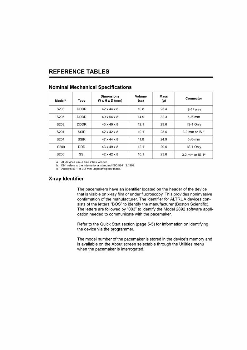
X-ray Identifier
The pacemakers have an identifier located on the header of the device that is visible on x-ray film or under fluoroscopy. This provides noninvasive confirmation of the manufacturer. The identifier for ALTRUA devices con-sists of the letters “BOS” to identify the manufacturer (Boston Scientific). The letters are followed by “003” to identify the Model 2892 software appli-cation needed to communicate with the pacemaker.
Refer to the Quick Start section (page 5-5) for information on identifying the device via the programmer.
The model number of the pacemaker is stored in the device's memory and is available on the About screen selectable through the Utilities menu when the pacemaker is interrogated.
Modela
a. All devices use a size 2 hex wrench.
TypeDimensions
W x H x D (mm)Volume
(cc)Mass
(g) Connector
S203 DDDR 42 x 44 x 8 10.8 25.4 IS-1b only
b. IS-1 refers to the international standard ISO 5841.3:1992.
S205 DDDR 49 x 54 x 8 14.9 32.3 5-/6-mm
S208 DDDR 43 x 49 x 8 12.1 29.6 IS-1 Only
S201 SSIR 42 x 42 x 8 10.1 23.6 3.2-mm or IS-1
S204 SSIR 47 x 44 x 8 11.0 24.9 5-/6-mm
S209 DDD 43 x 49 x 8 12.1 29.6 IS-1 Only
S206 SSI 42 x 42 x 8 10.1 23.6 3.2-mm or IS-1c
c. Accepts IS-1 or 3.2-mm unipolar/bipolar leads.
ii
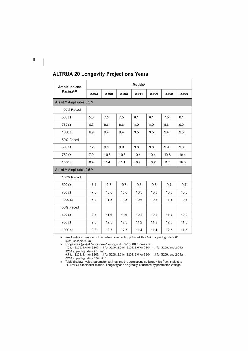
ALTRUA 20 Longevity Projections Years
Amplitude and Pacinga,b
a. Amplitudes shown are both atrial and ventricular; pulse width = 0.4 ms, pacing rate = 60 min-¹, sensors = On.
b. Longevities (yrs) at "worst case" settings of 5.0V, 500Ω, 1.0ms are:1.0 for S203, 1.4 for S205, 1.4 for S208, 2.6 for S201, 2.6 for S204, 1.4 for S209, and 2.6 for S206 at pacing rate = 70 min-1
0.7 for S203, 1.1 for S205, 1.1 for S208, 2.0 for S201, 2.0 for S204, 1.1 for S209, and 2.0 for S206 at pacing rate = 100 min-1.
Modelsc
c. Table displays typical parameter settings and the corresponding longevities from implant to ERT for all pacemaker models. Longevity can be greatly influenced by parameter settings.
S203 S205 S208 S201 S204 S209 S206
A and V Amplitudes 3.5 V
100% Paced
500 Ω 5.5 7.5 7.5 8.1 8.1 7.5 8.1
750 Ω 6.3 8.6 8.6 8.9 8.9 8.6 9.0
1000 Ω 6.9 9.4 9.4 9.5 9.5 9.4 9.5
50% Paced
500 Ω 7.2 9.9 9.9 9.8 9.8 9.9 9.8
750 Ω 7.9 10.8 10.8 10.4 10.4 10.8 10.4
1000 Ω 8.4 11.4 11.4 10.7 10.7 11.5 10.8
A and V Amplitudes 2.5 V
100% Paced
500 Ω 7.1 9.7 9.7 9.6 9.6 9.7 9.7
750 Ω 7.8 10.6 10.6 10.3 10.3 10.6 10.3
1000 Ω 8.2 11.3 11.3 10.6 10.6 11.3 10.7
50% Paced
500 Ω 8.5 11.6 11.6 10.8 10.8 11.6 10.9
750 Ω 9.0 12.3 12.3 11.2 11.2 12.3 11.3
1000 Ω 9.3 12.7 12.7 11.4 11.4 12.7 11.5

iii
Magnet Test and Battery Operation
Features List
Refer to Chapter 6, “Therapy” and Chapter 7, “Diagnostics and Follow-Up” for com-plete descriptions of the features.
Diagnostic Features• Semiautomatic Threshold Tests
• Interactive P- and R-Wave Amplitude measurements
• Interactive A and V Lead Impedance measurements
• Event Counters
• Sensor trending
• Rate Histograms
• Real-time intracardiac EGMs
• Annotated Event Markers
• Automatic Stored EGM
• Patient-Triggered Stored EGM
• High-Resolution Rate trending
• Beat-to-Beat Holter
• Arrhythmia Logbook
Magnet Ratea
a. To perform a battery test using the magnet, the magnet operation must be programmed to Async. The AV Delay during a magnet test is 100 ms. The third pulse of the magnet test is at 50% of the programmed Pulse Width to allow evalua-tion of the pacing safety margin.
Battery Status Comments
100 min-¹ BOL (Beginning of Life) Perform normally scheduled follow-ups
90 min-¹ ERN (Elective Replace-ment Near)
Intensify follow-ups
85 min-¹ ERT (Elective Replace-ment Time)
Schedule replacement.
For adaptive-rate modes only: When the pacemaker reaches ERT, the mode will change to nonadaptive rate mode (e.g., DDDR to DDD, VVIR to VVI, etc)
85 min-¹ or less EOL (End of Life) Three months after ERT, the device will reach EOL. When EOL is reached, dual-chamber pacemakers will change modes to single-chamber operation (DDD and VDD revert to VVI) and the LRL will be lowered to 50 min-¹. Schedule replacement immediately.

iv
• Daily P- and R-Wave Amplitude measurements and trend
• Daily A and V Lead Impedance measurements and trend
• Quick Check
Therapy Features• Accelerometer
• A-Tachy Response
• Dynamic AV Delay
• PVARP after PVC/PAC
• PMT Termination
• Rate Smoothing
• Sensed AV Offset
• (Sensor) Rate Hysteresis
• Programmed Electrical Stimulation/Burst
• Sudden Brady Response
• Safety Switch

1-1
INFORMATION FOR USE
CHAPTER 1
This chapter includes the following information associated with the ALTRUA 20 pacemakers.
• Device Description
• Indications and Usage
• Contraindications
• Warnings and Precautions
• Adverse Events
• Product Reliability
• Patient Counseling Information
INFORMATION FOR USEDEVICE DESCRIPTION
1-2
DEVICE DESCRIPTION
The ALTRUA 20 pacemakers are multiprogrammable. The family consists of both dual-chamber and single-chamber models, offering adaptive-rate therapy as well as various levels of therapeutic and diagnostic functionality. The pacemakers feature IS-11, 3.2-mm/IS-1, and 5-/6-mm connectors. The 3.2-mm/IS-1 connectors accept both IS-1 and 3.2-mm leads. Refer to page iii in the front of the manual for a list of features.
The ALTRUA 20 pacemakers have an accelerometer (motion sensor) that responds to patient activity. Refer to Chapter 3, “Technical Information” for a detailed descrip-tion of the accelerometer.
INDICATIONS AND USAGE
ALTRUA 20 pacemakers are indicated for treatment of the following:
• Symptomatic paroxysmal or permanent second- or third-degree AV block
• Symptomatic bilateral bundle branch block
• Symptomatic paroxysmal or transient sinus node dysfunction with or without associated AV conduction disorders (e.g., sinus bradycardia, sinus arrest, sino-atrial block)
• Bradycardia-tachycardia syndrome, to prevent symptomatic bradycardia or some forms of symptomatic tachyarrhythmias
• Neurovascular (vaso-vagal) syndromes or hypersensitive carotid sinus syn-dromes
Adaptive-rate pacing is indicated for patients who may benefit from increased pac-ing rates concurrent with an increase in level of physical activity.
The ALTRUA 20 pacemakers’ dual-chamber and atrial tracking modes are also indi-cated for patients who may benefit from maintenance of AV synchrony. Dual-cham-ber modes are specifically indicated for treatment of the following:
1. IS-1 refers to the international standard ISO 5841.3:1992.
INFORMATION FOR USECONTRAINDICATIONS
1-3
• Conduction disorders that require restoration of AV synchrony, including varying degrees of AV block
• VVI intolerance (e.g., pacemaker syndrome) in the presence of persistent sinus rhythm
• Low cardiac output or congestive heart failure secondary to bradycardia
CONTRAINDICATIONS
The ALTRUA 20 pacemakers are contraindicated for the following applications:
• Patients with unipolar pacing leads with an implanted cardioverter-defibrillator (ICD), because it may cause unwanted delivery or inhibition of ICD therapy
• Single-chamber atrial pacing in patients with impaired AV nodal conduction
• Atrial tracking modes for patients with chronic refractory atrial tachyarrhythmias (atrial fibrillation or flutter), which might trigger ventricular pacing
• Dual-chamber and single-chamber atrial pacing in patients with chronic refrac-tory atrial tachyarrhythmias
• Asynchronous pacing in the presence (or likelihood) of competition between paced and intrinsic rhythms
WARNINGS AND PRECAUTIONS
Clinical Considerations
• In devices with the Safety Switch programmed to On, the lead polarity will revert to unipolar in the presence of a lead impedance of < 100 Ω or > 2500 Ω. Unipo-lar pacing is contraindicated for patients with an ICD.
• STAT PACE will initiate unipolar pacing, which is contraindicated for patients with an ICD.
• Adaptive-rate pacing should be used with care in patients unable to tolerate increased pacing rates.
INFORMATION FOR USEWARNINGS AND PRECAUTIONS
1-4
• Use of AAT or VVT modes outside of a diagnostic setting is not recommended due to the potential for triggered pacing in response to oversensing.
• Slow retrograde conduction combined with a short PVARP might induce pace-maker-mediated tachycardia.
Sterilization, Storage, and Handling
• Storage Temperature and Equilibration. Recommended storage temperatures are 0°C–50°C (32°F–122°F). Allow the device to reach room temperature before programming or implanting the device because temperature extremes may affect initial device function. Extremely low temperatures (below –20°C) could result in permanent memory loss. If this occurs, as indi-cated by a programmer error message, return the device to Boston Scientific for inspection.
• For single patient use only. Do not reuse, reprocess, or resterilize. Reuse, reprocessing, or resterilization may compromise the structural integrity of the device and/or lead to device failure which, in turn, may result in patient injury, ill-ness, or death. Reuse, reprocessing, or resterilization may also create a risk of contamination of the device and/or cause patient infection or cross-infection, including, but not limited to, the transmission of infectious disease(s) from one patient to another. Contamination of the device may lead to injury, illness, or death of the patient.
Do not implant a pacemaker if any of the following conditions apply:
• The pacemaker is dropped onto a hard surface. Return the device to Boston Scientific for inspection.
• Use by date. Implant the device system before or on the USE BY date on the package label because this date reflects a validated shelf life. For example, if the date is January 1, do not implant on or after January 2. If a pacemaker with an expired “USE BY” date is implanted, the pacemaker warranty is void.
• The storage package has been pierced or altered, because this could have ren-dered it nonsterile.
INFORMATION FOR USEWARNINGS AND PRECAUTIONS
1-5
Lead Evaluation and Connection
• Pacing and sensing safety margins. Consider lead maturation in choice of pacing amplitudes, pacing pulse widths, and sensing levels.
• Acute pacing thresholds greater than 1.5 V or chronic pacing thresholds greater than 3 V can result in loss of capture because thresholds increase after implantation.
• R-wave amplitude less than 5 mV or P-wave amplitude less than 2 mV can result in undersensing because sensed amplitude decreases after implantation.
• Pacing lead impedance should be within the range of 100 Ω and 2500 Ω.
• Line-powered equipment. Exercise extreme caution if testing leads using line-powered equipment, because leakage current exceeding 10 μA can induce ventricular fibrillation.
• Setscrew position. Do not insert a lead into the pacemaker connector without first visually verifying that the setscrews are sufficiently retracted to allow inser-tion.
• Pacemaker/lead compatibility. Prior to implanting this pacemaker, verify lead/pacemaker compatibility with Technical Services.
• Proper programming of the lead configuration. If the Lead Configuration is programmed to Bipolar when a unipolar lead is implanted, pacing will not occur.
Implantation
• Implanting a replacement pacemaker in a subcutaneous pocket that previously housed a larger device may result in pocket air entrapment, migra-tion, erosion, or insufficient grounding between the device and tissue. Flooding the pocket with sterile saline solution decreases the possibility of pocket air entrapment and insufficient grounding. Suturing the device in place reduces the possibility of migration and erosion.

INFORMATION FOR USEWARNINGS AND PRECAUTIONS
1-6
Programming and Pacemaker Operation
• Use a Boston Scientific ZOOM LATITUDE Programming System, which includes the Model 2892 CONSULT Software Application to communicate with the ALTRUA 20 pacemakers.
• Telemetry communication can be interrupted by electrical noise, thus pre-venting improper interrogation or programming. If the message window appears indicating that the wand is out of range or there is telemetry noise, move the PRM and/or the wand away from such electrical devices as electro-surgical and monitoring equipment and ensure that the wand cord and cables are not crossing one another. Telemetry communication will resume when the noise source is removed. The message window also has a Cancel button that, when selected, will stop the interrogation.
• A pacemaker programmed to STAT pacing, if not reprogrammed, will con-tinue to pace in SSI mode at the high-energy STAT values. Reprogram the pacemaker to other parameter settings for alternative patient therapies or to extend pacemaker longevity.
• Adaptive-rate pacing is not limited by refractory periods. A long refractory period programmed in combination with a high MSR can result in asynchronous pacing during refractory periods, since the combination can cause a very small sensing window or none at all. Use Dynamic AV Delay to optimize sensing win-dows.
• If the Amplitude is Off during temporary programming, the pacemaker will not pace. Pacing with the permanently programmed parameters can be restored by breaking the telemetry link or by selecting the Cancel button on the Temporary Parameters Now in Use dialogue window.
Environmental and Medical Therapy Hazards
Patients should be directed to avoid devices that generate strong electric or mag-netic interference (EMI). If the pacemaker inhibits or reverts to asynchronous opera-tion at the programmed pacing rate or at the magnet rate while in the presence of the EMI, moving away from the source or turning it off will usually allow the pulse generator to return to its normal mode of operation.

INFORMATION FOR USEWARNINGS AND PRECAUTIONS
1-7
Radio and Telecommunications Terminal Equipment (RTTE)
Boston Scientific declares that this device is in compliance with the essential requirements and other relevant provisions of the current RTTE directive.
Hospital and Medical Environments
Confirm pacemaker operation after any of the following medical procedures.
• Electrosurgical cautery could induce ventricular arrhythmias and/or fibrillation, may cause asynchronous or inhibited pacemaker operation, or may trigger the EOL indicator. If electrocautery cannot be avoided, observe the following pre-cautions to minimize complications:
• Program the device to the VOO/AOO/DOO mode and avoid direct contact with the pacemaker or leads.
• Position the ground plate so that the current pathway does not pass through or near the pacemaker system.
• Use short, intermittent, and irregular bursts at the lowest feasible energy levels.
• Use a bipolar electrocautery system where possible.
• Have temporary pacing and defibrillation equipment available.
• Radio-frequency (RF) ablation. Exercise caution when performing radio fre-quency (RF) ablation procedures, or any other type of cardiac ablation proce-dure in patients with implanted devices. RF ablation may cause: asynchronous pacing or inhibition of pacing, pacemaker reset, ventricular pacing up to the MTR, ventricular fibrillation, and/or changes in pacing thresholds. RF noise can interfere with telemetry communication between the pulse generator and pro-grammer potentially preventing pacemaker interrogation or programming during RF ablation. Check pulse generator and lead function post ablation. Minimize risks by following these steps:
• Monitor the patient and have temporary pacing and defibrillation equipment, and knowledgeable medical personnel available.
• For pacemaker-dependent patients, consider the use of external pacing support (e.g., using internal or external pacing methods).
INFORMATION FOR USEWARNINGS AND PRECAUTIONS
1-8
• For pacemaker-dependent patients, program the pulse generator Brady Mode to DOO, VOO, or AOO, as appropriate, to prevent radio frequency noise from inhibiting pacing therapy. Alternatively, a magnet can be placed over the device to pace asynchronously at the magnet rate. Other options may be considered when the patient has intrinsic rhythm (e.g., program-ming the device to VVI at a rate below the intrinsic rate to avoid competitive pacing).
• Avoid direct contact between the ablation catheter and the implanted lead. Radio frequency ablation close to the lead electrode may damage the lead-tissue interface.
• Position the ground plate so that the current pathway passes as far away from the pulse generator and leads as possible.
• Monitor pre and post measurements for sensing and pacing thresholds and impedances to verify lead-tissue interface and lead integrity.
If any programming changes were made, the pulse generator should be pro-grammed back to the appropriate settings following the procedure.
• Magnetic resonance imaging (MRI) for pacemaker patients has been contra-indicated by MRI manufacturers. Clinicians should carefully weigh the decision to use MRI with pacemaker patients.
• Magnetic and RF fields produced by MRI may increase ventricular pacing beyond the rate limit, result in total inhibition of pacing output, result in pacing at random rates, or result in asynchronous pacing.
• Magnetic fields may activate magnet mode operation and cause asynchro-nous pacing.
• MRI can irreversibly damage the pacemaker.
• Pacemaker patients treated with MRI should be closely monitored and programmed parameters should be verified upon cessation of MRI.
• Lithotripsy may permanently damage the pacemaker if the device is at the focal point of the lithotripsy beam. If lithotripsy must be used, do not focus near the pacemaker site. The lithotriptor is designed to trigger off the R-wave on the ECG resulting in shock waves being delivered during the ventricular refractory
INFORMATION FOR USEWARNINGS AND PRECAUTIONS
1-9
period. Program to VVI/VOO mode because atrial pacing pulses can trigger the lithotriptor.
• Therapeutic ultrasound energy may damage the pulse generator. If therapeutic ultrasound energy must be used, avoid focusing near the pulse gen-erator site.
• Therapeutic diathermy may cause fibrillation, burning of the myocardium, and irreversible damage to the pacemaker because of induced currents.
• External defibrillation. Use of external defibrillation can damage the pulse generator. To help prevent defibrillation damage to the pulse generator, con-sider the following:
• Avoid placing a pad (or paddle) directly over the pulse generator. Position the external defibrillation pads (or paddles) as far from the pulse generator as possible.
• Position the external defibrillation pads (or paddles) in a ‘posterior-anterior’ orientation when the device is implanted in the right pectoral region or an ‘anterior-apex’ orientation when the device is implanted in the left pectoral region.
• Set energy output of external defibrillation equipment as low as clinically acceptable.
Following any external defibrillation episode, verify pulse generator function since external defibrillation may have damaged the pulse generator. Interrogate the pulse generator, verify battery status, verify pacing and ensure that programmable parameters did not change.
• Transcutaneous electrical nerve stimulation (TENS) may interfere with pacemaker function. If necessary, the following measures may reduce interfer-ence:
• Place the TENS electrodes as close to each other as possible.
• Place the TENS electrodes as far from the pacemaker/lead system as possible.
• Monitor cardiac activity during TENS use.

INFORMATION FOR USEWARNINGS AND PRECAUTIONS
1-10
• Diagnostic x-ray and fluoroscopic radiation should not affect the pacemaker. For high radiation sources, see Ionizing radiation therapy warning below.
• Ionizing radiation. Many sources of ionizing radiation are commonly used for the diagnosis and treatment of diseases; these sources vary significantly in their potential impact on an implanted pulse generator. Several therapeutic radiation sources are capable of interfering with or damaging an implanted pulse genera-tor, including those used for the treatment of cancer, such as radioactive cobalt, linear accelerators, radioactive seeds, and betatrons.
Most diagnostic tools, such as radiography (X-ray) and fluoroscopy, have not been identified as sources of device interference or damage. The impact of ionizing radia-tion will also vary from one pulse generator to another and may range from no changes in function to a loss of pacing.
It is not possible to specify a ‘safe’ radiation dosage or guarantee proper pulse gen-erator function following exposure to ionizing radiation. Multiple factors collectively determine the impact of radiation therapy on an implanted pulse generator, includ-ing proximity of the pulse generator to the radiation beam, type and energy level of the radiation beam, dose rate, total dose delivered over the life of the pulse genera-tor, and shielding of the pulse generator.
Refer to the Post-Implant section of the System Guide for further details regarding advance planning and follow-up assessment of pulse generators exposed to ioniz-ing radiation.
Home and Occupational Environments
Patients should be advised of the following potential sources of EMI:
• High-voltage power transmission lines might generate enough EMI to inter-fere with pacemaker operation if approached too closely.
• Communication equipment such as microwave transmitters, linear-power amplifiers, or high-powered amateur transmitting systems might gener-ate enough EMI to interfere with pacemaker operation if approached too closely.
• Commercial electrical equipment such as arc welders, induction furnaces, or resistance welders might generate enough EMI to interfere with pacemaker operation if approached too closely.
INFORMATION FOR USEWARNINGS AND PRECAUTIONS
1-11
• Electronic article surveillance (EAS) equipment such as retail theft preven-tion systems might interact with pulse generators. Patients should be advised to walk directly through and not to remain near an EAS system longer than is nec-essary.
• Home appliances that are in good working order and properly grounded do not usually produce enough EMI to interfere with pulse generator operation. There are reports of pulse generator disturbances caused by electric hand tools or electric razors used directly over the pulse generator implant site.
Cellular Phones
Patients having an implanted pacemaker who operate a cellular phone should observe the following precautions:
• Maintain a minimum separation of 6 inches (15 cm) between a handheld per-sonal cellular phone and the implanted device. Portable and mobile cellular phones generally transmit at higher power levels compared to handheld mod-els. For phones transmitting above 3 watts, maintain a minimum separation of 12 inches (30 cm) between the antenna and the implanted device.
• Hold the phone to the ear opposite the side of the implanted device. Patients should not carry the phone in a breast pocket or on a belt over or within 6 inches (15 cm) of the implanted device as some phones emit signals when they are turned On but not in use (i.e., in the listen or standby mode). Store the phone in a location opposite the side of the implant site.
Elevated Pressure
The information provided here is a summary of pressure testing completed by Bos-ton Scientific; it should not be viewed as and is not an endorsement of HBOT treat-ment or SCUBA diving activities. During laboratory testing of ALTRUA, all devices in the test sample (statistically significant) continued to function as designed when exposed to more than 100 cycles at a pressure up to 5.0 ATA. Pressure for each test cycle began at ambient/room pressure, increased to a high pressure level, and then returned to ambient pressure. Although dwell time (the amount of time under elevated pressure) may have an impact on human physiology, testing indicated it did not impact device performance.
Since our pressure testing was conducted in a laboratory environment, it did not characterize the impact of elevated pressure on device performance or physiologi-cal response while implanted in a human body. Prior to engaging in activities such

INFORMATION FOR USEWARNINGS AND PRECAUTIONS
1-12
as HBOT or SCUBA diving, a patient should consult their attending cardiologist or electrophysiologist to fully understand the potential consequences of these activities relative to their specific health condition.
INFORMATION FOR USEADVERSE EVENTS
1-13
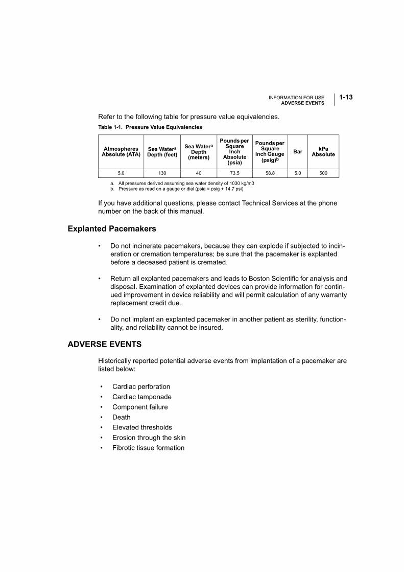
Refer to the following table for pressure value equivalencies.
Explanted Pacemakers
• Do not incinerate pacemakers, because they can explode if subjected to incin-eration or cremation temperatures; be sure that the pacemaker is explanted before a deceased patient is cremated.
• Return all explanted pacemakers and leads to Boston Scientific for analysis and disposal. Examination of explanted devices can provide information for contin-ued improvement in device reliability and will permit calculation of any warranty replacement credit due.
• Do not implant an explanted pacemaker in another patient as sterility, function-ality, and reliability cannot be insured.
ADVERSE EVENTS
Historically reported potential adverse events from implantation of a pacemaker are listed below:
Table 1-1. Pressure Value Equivalencies
Atmospheres Absolute (ATA)
Sea WateraDepth (feet)
a. All pressures derived assuming sea water density of 1030 kg/m3
Sea WateraDepth
(meters)
Pounds per Square
Inch Absolute
(psia)
Pounds per Square
Inch Gauge (psig)b
b. Pressure as read on a gauge or dial (psia = psig + 14.7 psi)
If you have additional questions, please contact Technical Services at the phone number on the back of this manual.
Bar kPa Absolute
5.0 130 40 73.5 58.8 5.0 500
• Cardiac perforation
• Cardiac tamponade
• Component failure
• Death
• Elevated thresholds
• Erosion through the skin
• Fibrotic tissue formation
INFORMATION FOR USEPRODUCT RELIABILITY
1-14
PRODUCT RELIABILITY
It is Boston Scientific’s intent to provide implantable devices of high quality and reli-ability. However, these devices may exhibit malfunctions that may result in lost or compromised ability to deliver therapy. These malfunctions may include the follow-ing:
• Premature battery depletion
• Sensing or pacing issues
• Error codes
• Loss of telemetry
Refer to Boston Scientific’s CRM Product Performance Report on www.bostonsci-entific.com for more information about device performance, including the types and rates of malfunctions that these devices have experienced historically. While histori-cal data may not be predictive of future device performance, such data can provide important context for understanding the overall reliability of these types of products.
Sometimes device malfunctions result in the issuance of product advisories. Boston Scientific determines the need to issue product advisories based on the estimated malfunction rate and the clinical implication of the malfunction. When Boston Scien-tific communicates product advisory information, the decision whether to replace a device should take into account the risks of the malfunction, the risks of the replace-ment procedure, and the performance to date of the replacement device.
• Foreign body rejection phenomena
• Hematoma/seroma
• Inability to provide therapy (pacing/sensing)
• Infection
• Lead abrasion
• Lead fracture, insulation break
• Local tissue reaction
• Myopotential sensing
• Nerve and muscle stimulation
• Pacemaker mediated tachycardia (PMT)
• Pacemaker migration
• Transvenous lead-related thrombosis
INFORMATION FOR USEPATIENT COUNSELING INFORMATION
1-15
PATIENT COUNSELING INFORMATION
The following are topics that the clinician might want to discuss with the patient prior to discharge:
• Signs and symptoms of infection
• Symptoms that should be reported (e.g., sustained high-rate pacing requiring reprogramming)
• Activity restrictions (if applicable)
• Minimum heart rate (lower rate limit of the pacemaker)
• Frequency of follow-up
• It is Boston Scientific’s intent to provide implantable devices of high quality and reliability. However, these devices may exhibit malfunctions that may result in lost or compromised ability to deliver therapy. When Boston Scientific communi-cates product advisory information, the decision whether to replace a device should take into account the risks of the malfunction, the risks of the replace-ment procedure, and the performance to date of the replacement device.
Patient Handbook
A copy of the patient handbook is available for the patient, patient’s relatives, and other interested people. Discuss the information in the handbook with concerned individuals both before and after pacemaker implantation so they are fully familiar with operation of the device. For additional copies of the patient handbook, contact your sales representative or contact Boston Scientific at the phone number on the back cover of this manual.
Patient Identification (ID) Card
A patient identification (ID) card is packaged with each device. The patient should be advised to carry the patient ID card at all times.

INFORMATION FOR USEPATIENT COUNSELING INFORMATION
1-16

2-1
PRE-IMPLANT AND IMPLANT INFORMATION
CHAPTER 2
This chapter discusses procedures used when implanting the ALTRUA 20 pacemakers. The following topics are discussed:
• Storage
• Opening Instructions
• Items Included
• Sterilization
• Lead Connections
• Pacemaker Insertion
PRE-IMPLANT AND IMPLANT INFORMATIONSTORAGE
2-2
STORAGE
Take the following precautions when storing or handling a pacemaker:
CAUTIONS:
• Never attempt to resterilize a pacemaker or the wrench packaged with it. Instead, return the pacemaker to Boston Scientific.
• Use by date. Implant the device system before or on the USE BY date on the package label because this date reflects a validated shelf life. For example, if the date is January 1, do not implant on or after January 2. If a pacemaker with an expired “USE BY” date is implanted, the pacemaker warranty is void.
• Some conditions and exposure to low preimplant temperatures (lower than 0° C) during shipping or storage may cause an electrical reset to occur. In these cases, warm the device to room temperature and, if possible, clear the status with the programmer. If this is not possible, call Technical Services.
• Storage Temperature and Equilibration. Recommended storage temperatures are 0°C–50°C (32°F–122°F). Allow the device to reach room temperature before programming or implanting the device because temperature extremes may affect initial device function. Extremely low temperatures (below –20°C) could result in permanent memory loss. If this occurs, as indicated by a programmer error message, return the device to Boston Scientific for inspection.
• Do not implant a pacemaker if the storage package has been pierced or altered, because this could have rendered it nonsterile.
• If a pacemaker is dropped onto a hard surface, do not implant it. Return the device to Boston Scientific for inspection.
OPENING INSTRUCTIONS
Before beginning the implantation procedure, become completely familiar with the operation of all the equipment and the information in the respective operator’s and user’s manuals.
The outer package and sterile trays should be opened by authorized personnel under clean conditions. To ensure sterility, the sealed inner tray must be opened
PRE-IMPLANT AND IMPLANT INFORMATIONITEMS INCLUDED
2-3
using accepted aseptic technique by scrubbed, masked, sterile-gowned personnel. The sterile trays are opened by peeling back the covers.
ITEMS INCLUDED
Each pacemaker is packaged with one bidirectional torque wrench and product literature.
STERILIZATION
The pacemaker blister trays and contents are sterilized with ethylene oxide gas before final packaging. When the pacemaker is received, it is sterile, provided the container is intact. If the packaging is wet, punctured, opened, or otherwise damaged, return the device to Boston Scientific.
WARNING: For single patient use only. Do not reuse, reprocess, or resterilize. Reuse, reprocessing, or resterilization may compromise the structural integrity of the device and/or lead to device failure which, in turn, may result in patient injury, illness, or death. Reuse, reprocessing, or resterilization may also create a risk of contamination of the device and/or cause patient infection or cross-infec-tion, including, but not limited to, the transmission of infectious disease(s) from one patient to another. Contamination of the device may lead to injury, illness, or death of the patient.
LEAD CONNECTIONS
ALTRUA 20 pacemakers are available with various lead connectors that accept IS-1, 3.2-mm, and 5-/6-mm leads.
Lead selection depends on the needs of each patient. The longevity of this product, as with other pacemakers, may be enhanced by using high-impedance pacing leads. Using a bipolar lead will reduce the chance of myopotential sensing.
Refer to the lead's instruction manual for implant information, general warnings and precautions, indications, contraindications, and technical specifications. Read this material carefully for implant procedure instructions specific to the chosen lead configurations.
CAUTIONS:
• Prior to implanting this pacemaker, verify lead/pacemaker compatibility with Technical Services.
PRE-IMPLANT AND IMPLANT INFORMATIONLEAD CONNECTIONS
2-4
• If using an IS-1 or 3.2-mm unipolar lead not manufactured by Boston Scientific with the ALTRUA pacemakers, be sure the lead has an anode terminal protector to permit tightening of the proximal setscrew. All Boston Scientific IS-1 and 3.2-mm leads have this protector. Contact Technical Services for assistance.
• The absence of a lead or plug in a lead port may affect device performance. If a lead is not used, be sure to properly insert a plug in the unused port.
• Exercise extreme caution if testing leads using line-powered equipment, because leakage current exceeding 10 μA can induce ventricular fibrillation.
• Consider lead maturation in choice of pacing amplitude and sensitivity, for the following reasons:
• Acute pacing thresholds greater than 1.5 V or chronic pacing thresholds greater than 3 V can result in loss of capture because thresholds increase after implantation.
• R-wave amplitude less than 5 mV or P-wave amplitude less than 2 mV can result in undersensing because sensed amplitude decreases after implantation.
• Pacing lead impedance should be within the range of 100 Ω to 2500 Ω.
• Proper programming of the Lead Configuration is essential. If the Lead Configu-ration is programmed to Bipolar when a unipolar lead is implanted, pacing will not occur.
Lead Adapters
When replacing another pacemaker with an ALTRUA pacemaker, you may need to use an adapter that will enable you to connect the new pacemaker to the existing leads. Refer to Table 2-1 to determine the correct model and adapter.
PRE-IMPLANT AND IMPLANT INFORMATIONLEAD CONNECTIONS
2-5
When using an adapter, follow the connection procedure described in the applicable adapter product data sheet. Always connect the adapter to the lead and repeat threshold and sensing measurements before connecting the adapter to the pacemaker.
Lead-to-Pacemaker Connection
After placing the lead and preparing a subcutaneous pocket, connect the lead to the pacemaker using the following procedure:
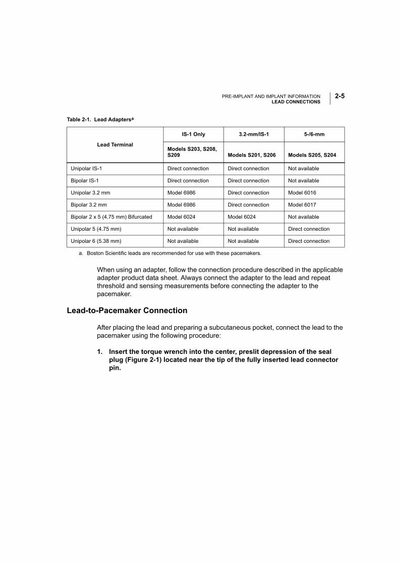
1. Insert the torque wrench into the center, preslit depression of the seal plug (Figure 2-1) located near the tip of the fully inserted lead connector pin.
Table 2-1. Lead Adaptersa
Lead Terminal
IS-1 Only 3.2-mm/IS-1 5-/6-mm
Models S203, S208, S209 Models S201, S206 Models S205, S204
Unipolar IS-1 Direct connection Direct connection Not available
Bipolar IS-1 Direct connection Direct connection Not available
Unipolar 3.2 mm Model 6986 Direct connection Model 6016
Bipolar 3.2 mm Model 6986 Direct connection Model 6017
Bipolar 2 x 5 (4.75 mm) Bifurcated Model 6024 Model 6024 Not available
Unipolar 5 (4.75 mm) Not available Not available Direct connection
Unipolar 6 (5.38 mm) Not available Not available Direct connection
a. Boston Scientific leads are recommended for use with these pacemakers.
PRE-IMPLANT AND IMPLANT INFORMATIONLEAD CONNECTIONS
2-6
Figure 2-1 Tightening the setscrews.
NOTE: The pacemaker features captured setscrews that require use of the bidirec-tional torque wrench included in the package. For additional information regarding setscrews, refer to the Guide to Replacement of Cardiac Implantable Pulse Generators.
CAUTION: Failure to properly insert the torque wrench into the preslit location of the seal plug could result in damage to the plug and its sealing properties. Fail-ure to use the supplied torque wrench could result in damage to the setscrew or connector threads.
2. Insert the lead terminal into the connector.
NOTE: If necessary, lubricate the lead terminal sparingly with sterile water to make insertion easier.
CAUTIONS:
• Do not insert a lead into the pacemaker connector without first visually verifying that the setscrews are sufficiently retracted to allow insertion.
• Insert the lead connector straight into the lead port. Do not bend the lead near the lead–header interface. Improper insertion (see following notes) can cause insulation damage near the terminal ring that could result in lead damage.
Seal plugs
PRE-IMPLANT AND IMPLANT INFORMATIONLEAD CONNECTIONS
2-7
NOTES:
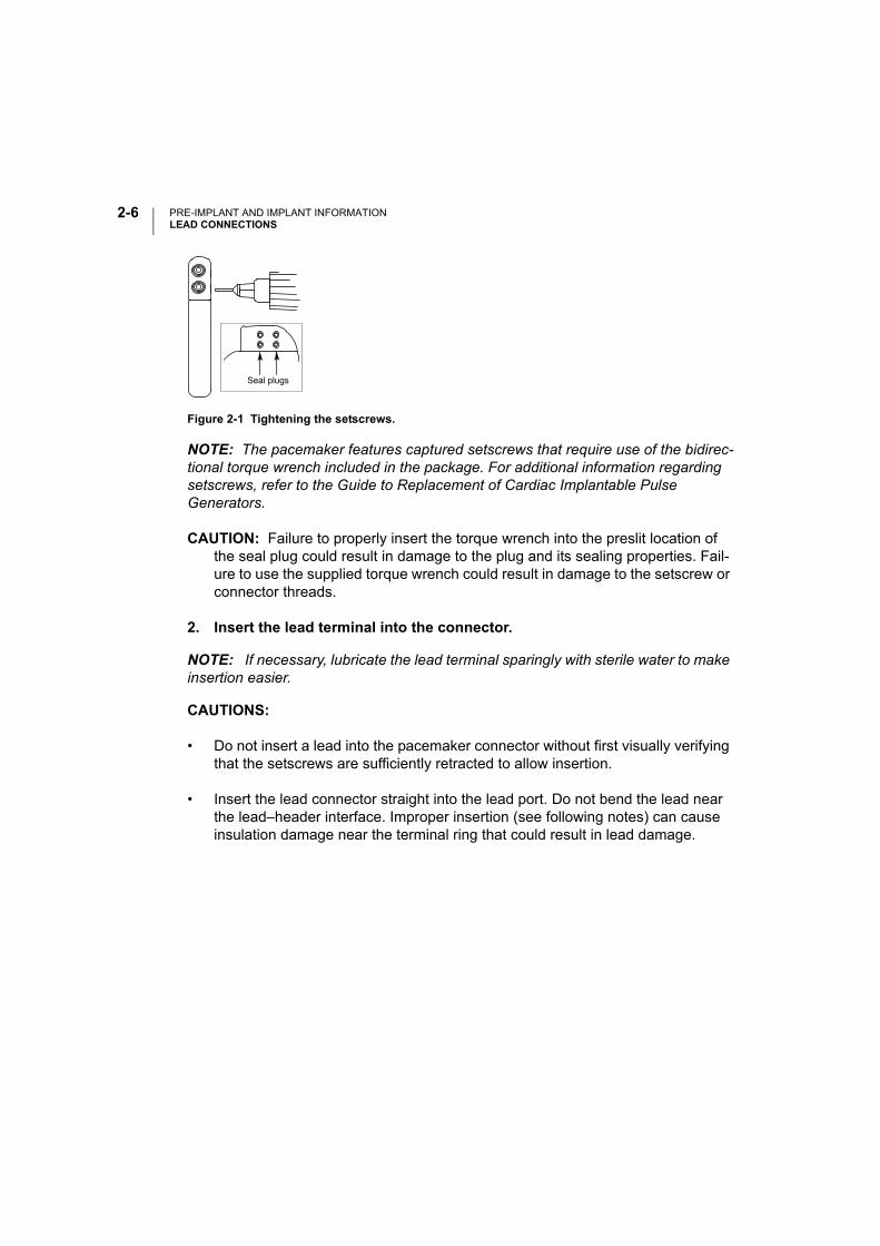
• For proper connection of an IS-1 lead to the pacemaker, be certain that the connector pin visibly extends through the connector block at least 1 mm (Figure 2-2).
Figure 2-2 The IS-1 connector.
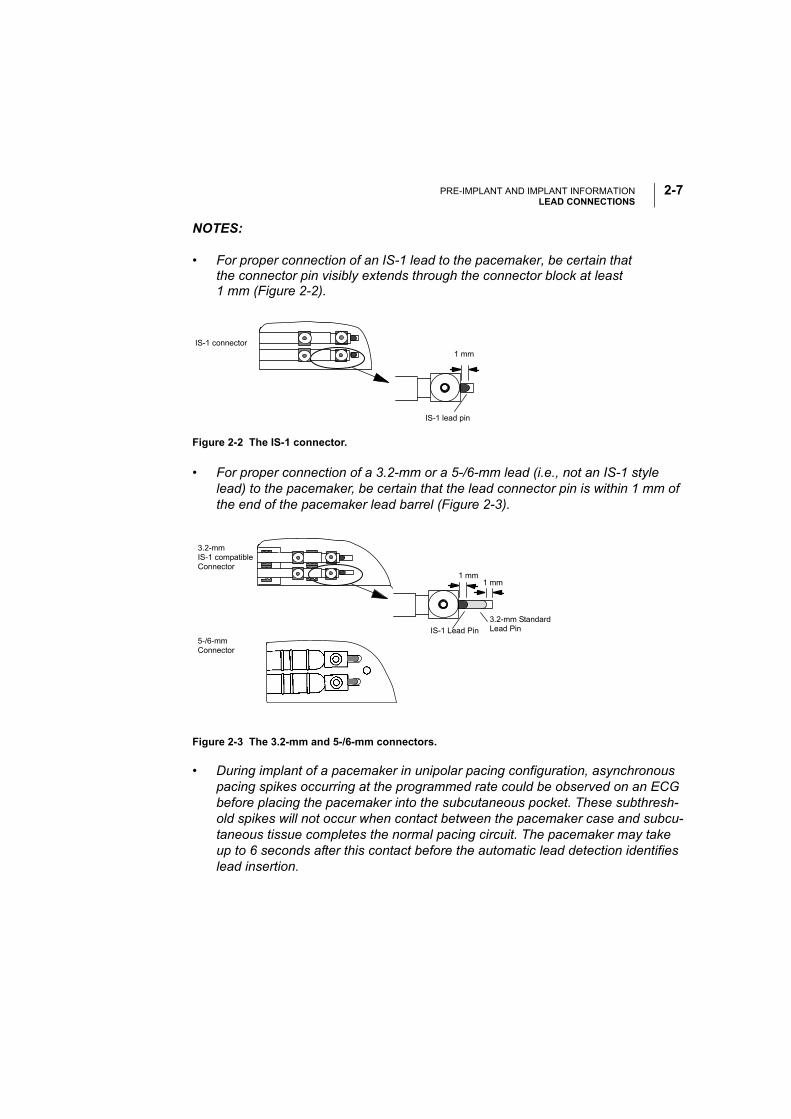
• For proper connection of a 3.2-mm or a 5-/6-mm lead (i.e., not an IS-1 style lead) to the pacemaker, be certain that the lead connector pin is within 1 mm of the end of the pacemaker lead barrel (Figure 2-3).
• During implant of a pacemaker in unipolar pacing configuration, asynchronous pacing spikes occurring at the programmed rate could be observed on an ECG before placing the pacemaker into the subcutaneous pocket. These subthresh-old spikes will not occur when contact between the pacemaker case and subcu-taneous tissue completes the normal pacing circuit. The pacemaker may take up to 6 seconds after this contact before the automatic lead detection identifies lead insertion.
Figure 2-3 The 3.2-mm and 5-/6-mm connectors.
1 mmIS-1 connector
IS-1 lead pin
3.2-mmIS-1 compatibleConnector
1 mm1 mm
IS-1 Lead Pin
3.2-mm Standard Lead Pin
5-/6-mm Connector
PRE-IMPLANT AND IMPLANT INFORMATIONPACEMAKER INSERTION
2-8
3. Maintain pressure on the lead to ensure that it remains fully inserted into the lead barrel.
4. Tighten the setscrews until the wrench handle ratchets.
Additional force is unnecessary as the torque wrench is preset to apply ade-quate force to the setscrew. Tighten the other setscrew(s) in a similar manner.
NOTE: For IS-1 and 3.2-mm lead connectors, electrical contact between the pace-maker and lead is established as soon as the lead connector is inserted into the lead barrel.
PACEMAKER INSERTION
Automatic Lead Implant Detection
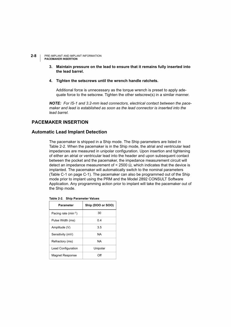
The pacemaker is shipped in a Ship mode. The Ship parameters are listed in Table 2-2. When the pacemaker is in the Ship mode, the atrial and ventricular lead impedances are measured in unipolar configuration. Upon insertion and tightening of either an atrial or ventricular lead into the header and upon subsequent contact between the pocket and the pacemaker, the impedance measurement circuit will detect an impedance measurement of < 2500 Ω, which indicates that the device is implanted. The pacemaker will automatically switch to the nominal parameters (Table C-1 on page C-1). The pacemaker can also be programmed out of the Ship mode prior to implant using the PRM and the Model 2892 CONSULT Software Application. Any programming action prior to implant will take the pacemaker out of the Ship mode.
Table 2-2. Ship Parameter Values
Parameter Ship (DOO or SOO)
Pacing rate (min-1) 30
Pulse Width (ms) 0.4
Amplitude (V) 3.5
Sensitivity (mV) NA
Refractory (ms) NA
Lead Configuration Unipolar
Magnet Response Off

PRE-IMPLANT AND IMPLANT INFORMATIONPACEMAKER INSERTION
2-9
The following will initialize and start once lead insertion has been detected (lead impedance < 2500 ohms):
• Daily Lead Impedance measurements
• Daily P- and R-wave measurements
• Arrhythmia Logbook (Ventricular Tachy Detection and A-Tachy Response triggers)
• Activity Log
The following will initialize and start when the device exits the Ship mode:
• Rate Trending
• Histograms and Counters
NOTES:
• If a bipolar pacing configuration is required at implant, program the Lead Config-uration to Bipolar before implant.
• Arrhythmia Logbook and Stored EGM data will not be stored for the first 2 hours after the lead is inserted into the header at implant.
Pacemaker Insertion Procedure
1. Place the pacemaker into the subcutaneous implant pocket.
CAUTION: If pacing is unipolar, be sure that permanent contact has been estab-lished between the pacemaker and subcutaneous tissue. Otherwise, the pace-maker might not function properly.
2. Verify pacemaker operation using an ECG.
If the patient’s intrinsic rhythm is above the programmed rate, use a magnet to temporarily switch the pacemaker to an asynchronous magnet rate at 100 min-¹ (see “Magnet Test” on page 4-4). If proper pacing and/or sensing are not dem-onstrated, disconnect the lead from the pacemaker and visually inspect the con-nector and leads. If necessary, retest the lead. Inadequate signals could indicate possible lead dislodgment, which would necessitate lead repositioning.

PRE-IMPLANT AND IMPLANT INFORMATIONPACEMAKER INSERTION
2-10
3. Suture the pacemaker in position.
Use the suture hole in the pacemaker top to secure the pacemaker in the sub-cutaneous pocket.
CAUTIONS:
• Implanting a replacement pacemaker in a subcutaneous pocket that previously housed a larger device may result in pocket air entrapment, migration, erosion, or insufficient grounding between the device and tissue. Flooding the pocket with sterile saline solution decreases the possibility of pocket air entrapment and insufficient grounding. Suturing the device in place reduces the possibility of migration and erosion.
• Before closing the subcutaneous pocket, ensure that the setscrews are properly tightened and that the pacemaker functions properly.

3-1
TECHNICAL INFORMATION
CHAPTER 3
This chapter includes the following technical information about the ALTRUA 20 pacemakers:
• Adaptive-Rate Sensors
• X-ray Identifier
• Minimizing Pacemaker/ICD Interaction
• Reset
• Output Pulse
• Output Circuit Recharge Cycle
• Runaway Protection
TECHNICAL INFORMATIONADAPTIVE-RATE SENSOR
3-2
ADAPTIVE-RATE SENSOR
One sensor, an accelerometer, is available with the ALTRUA 20 pacemakers. The accelerometer responds to patient activity (motion).
Accelerometer
The ALTRUA 20 pacemakers sense body motion by means of an integrated circuit accelerometer located on the hybrid circuit board. The accelerometer responds to activity in the frequency range of typical physiologic activity (1–10 Hz). An algorithm translates the measured acceleration in this range into a rate increase above the Lower Rate Limit. Because the accelerometer is not in contact with the pacemaker case, response to pressure applied to the pacemaker is negligible. See the “Sensor Submenu” section on page 6-16 for information on programming the accelerometer parameters.
X-RAY IDENTIFIER
The pacemakers have an identifier that is visible on x-ray film or under fluoroscopy. This provides noninvasive confirmation of manufacturer. The identifier for the ALTRUA devices consists of the letters “BOS” to identify the manufacturer (Boston Scientific). The letters are followed by 003, identifying the Model 2892 CONSULT Software Application needed to communicate with the pacemaker.
Refer to the Quick Start section (page 5-5) for information on identifying the device via the programmer.
The model number of the pacemaker is stored in the device’s memory and is available on the About screen, which can be accessed through the Utilities menu when the pacemaker is interrogated.
MINIMIZING PACEMAKER / ICD INTERACTION
The ALTRUA 20 pacemakers employ bipolar pacing and therefore are compatible for use with an implantable cardioverter defibrillator (ICD) when implanted with bipolar leads and programmed to bipolar pacing configuration.
A pacemaker can interact with an ICD in the following ways:
• If during a tachyarrhythmia the pacemaker is not inhibited and the pacing pulses are detected by the rate-sensing circuit of the ICD, the ICD could interpret the
TECHNICAL INFORMATIONMINIMIZING PACEMAKER / ICD INTERACTION
3-3
pacing pulses as a normal rhythm. The ICD would not detect the arrhythmia and therefore would not deliver therapy.
• Pacemaker failure to sense or to capture could result in two independent sig-nals (intrinsic and pacing pulses) to the ICD. This could cause the ICD’s rate measurement to be faster than the actual heart rate. As a result, the ICD could deliver unnecessary therapy.
• If the ICD counts both the pacing pulses and the resultant ventricular depolar-izations, the ICD’s rate measurement would be faster than the actual heart rate. This could result in unnecessary ICD therapy.
• An ICD shock could alter the pacemaker’s programmed settings or damage the pacemaker.
• An ALTRUA pacemaker concomitantly implanted with an ICD could experience a reset following the delivery of a shock from the ICD. Upon reset, the pace-maker will conduct a memory check to determine if the parameters essential for safe operation have been affected. If the parameters were not affected, the pacemaker will continue to operate as programmed. If essential parameters have been affected, the pacemaker will revert to VVI pacing mode, using pacing and sensing configurations as determined by a lead configuration test. The pacemaker can then be reprogrammed to the appropriate parameter settings.
To help minimize device–device interaction of a bipolar pacemaker when an ICD is already implanted, follow these precautionary measures:
• At implantation, place the pacemaker leads as far from the ICD sensing and defibrillating leads as possible. If an endocardial defibrillation lead is positioned in the right ventricle, consider using a positive fixation bipolar lead in the right ventricle and positioning the bipolar lead high on the septal wall or in the right ventricular outflow tract to get maximum distance between the bipolar pacing lead and the distal defibrillation coil. Place the atrial bipolar pacing lead as far as possible from the proximal defibrillation coil using a positive fixation bipolar pac-ing lead. Use of bipolar pacing leads with close electrode spacing (e.g., 11 mm) is recommended in both chambers.
• Consider programming the pacemaker to (1) the lowest amplitude allowable for safe capture in the chronic state, (2) the maximum sensitivity (the lowest pro-grammable level) while maintaining an adequate safety margin, and (3) the min-imum cardiac rate acceptable for the patient.
TECHNICAL INFORMATIONRESET
3-4
In addition to the above steps, perform the following testing to assess device–device interaction:
• Use the ICD features, such as markers, real-time electrograms (EGMs), and/or beeping tones, to help evaluate potential for pacemaker interaction due to over-sensing by the ICD.
• Ventricular fibrillation and all of the patient’s ventricular tachycardias should be induced while the ICD is activated and the pacemaker is programmed to an asynchronous mode at maximum amplitude and pulse width. This should pro-vide the greatest opportunity for inhibition of arrhythmia detection due to detec-tion of pacemaker pacing pulses. The pacemaker leads could have to be repositioned to eliminate detection of the pacing pulses by the ICD.
Temporarily deactivate the patient’s ICD when (1) evaluating pacing and sensing thresholds, (2) when using an external temporary pacemaker during implant, and (3) when reprogramming an implanted pacemaker.
Following any ICD discharge, reinterrogate the pacemaker to ensure that the programmed parameters have not been altered or that the ICD shock did not damage the pacemaker or cause a reset.
If implanting an ICD in a patient who has a pacemaker already implanted, refer to the ICD manual for implantation considerations.
WARNINGS:
• In devices with the Safety Switch programmed to On, the lead polarity will revert to Unipolar in the presence of a lead impedance of < 100 Ω or > 2500 Ω. Unipolar pacing is contraindicated for patients with an ICD.
• STAT PACE will initiate unipolar pacing, which is contraindicated for patients with an ICD.
RESET
Exposure of the pacemaker to certain conditions such as strong electrical interference from electrocautery or a defibrillation shock, or to low temperatures (prior to implantation) could cause a temporary reduction in the battery voltage. The pacemaker might be reset and conduct a memory check to determine if the parameters essential for safe operation have been affected. If the parameters were not affected, the pacemaker will continue to operate as programmed. If essential
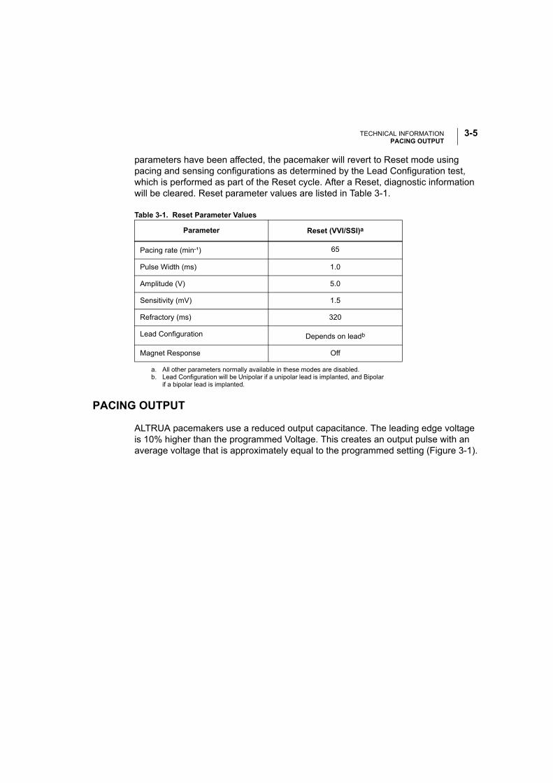
TECHNICAL INFORMATIONPACING OUTPUT
3-5
parameters have been affected, the pacemaker will revert to Reset mode using pacing and sensing configurations as determined by the Lead Configuration test, which is performed as part of the Reset cycle. After a Reset, diagnostic information will be cleared. Reset parameter values are listed in Table 3-1.
Table 3-1. Reset Parameter Values
PACING OUTPUT
ALTRUA pacemakers use a reduced output capacitance. The leading edge voltage is 10% higher than the programmed Voltage. This creates an output pulse with an average voltage that is approximately equal to the programmed setting (Figure 3-1).
Parameter Reset (VVI/SSI)a
a. All other parameters normally available in these modes are disabled.
Pacing rate (min-¹) 65
Pulse Width (ms) 1.0
Amplitude (V) 5.0
Sensitivity (mV) 1.5
Refractory (ms) 320
Lead Configuration Depends on leadb
b. Lead Configuration will be Unipolar if a unipolar lead is implanted, and Bipolar if a bipolar lead is implanted.
Magnet Response Off
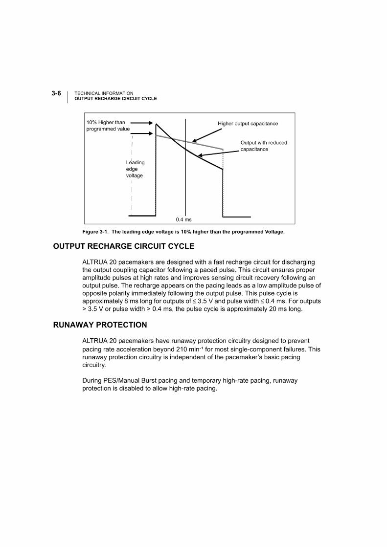
TECHNICAL INFORMATIONOUTPUT RECHARGE CIRCUIT CYCLE
3-6
OUTPUT RECHARGE CIRCUIT CYCLE
ALTRUA 20 pacemakers are designed with a fast recharge circuit for discharging the output coupling capacitor following a paced pulse. This circuit ensures proper amplitude pulses at high rates and improves sensing circuit recovery following an output pulse. The recharge appears on the pacing leads as a low amplitude pulse of opposite polarity immediately following the output pulse. This pulse cycle is approximately 8 ms long for outputs of ≤ 3.5 V and pulse width ≤ 0.4 ms. For outputs > 3.5 V or pulse width > 0.4 ms, the pulse cycle is approximately 20 ms long.
RUNAWAY PROTECTION
ALTRUA 20 pacemakers have runaway protection circuitry designed to prevent pacing rate acceleration beyond 210 min-¹ for most single-component failures. This runaway protection circuitry is independent of the pacemaker’s basic pacing circuitry.
During PES/Manual Burst pacing and temporary high-rate pacing, runaway protection is disabled to allow high-rate pacing.
Figure 3-1. The leading edge voltage is 10% higher than the programmed Voltage.
Higher output capacitance
Output with reducedcapacitance
10% Higher than programmed value
0.4 ms
Leadingedgevoltage

4-1
POSTIMPLANT INFORMATION
CHAPTER 4
This chapter includes information to be used following the implant of theALTRUA 20 pacemakers. The following topics are discussed in this chapter:
• Power Source
• Pacemaker Longevity Projections
• Battery Status
• Elective Replacement Time
• Explant Information
• Warranty Information
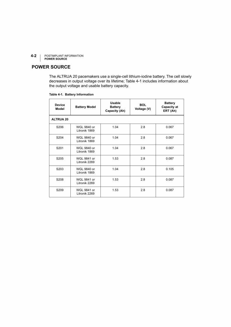
POSTIMPLANT INFORMATIONPOWER SOURCE
4-2
POWER SOURCE
The ALTRUA 20 pacemakers use a single-cell lithium-iodine battery. The cell slowly decreases in output voltage over its lifetime; Table 4-1 includes information about the output voltage and usable battery capacity.
Table 4-1. Battery Information
DeviceModel Battery Model
Usable Battery
Capacity (Ah)
BOL Voltage (V)
Battery Capacity at ERT (Ah)
ALTRUA 20
S206 WGL 9840 orLitronik 1869
1.04 2.8 0.067
S204 WGL 9840 orLitronik 1869
1.04 2.8 0.067
S201 WGL 9840 orLitronik 1869
1.04 2.8 0.067
S205 WGL 9841 orLitronik 2269
1.53 2.8 0.087
S203 WGL 9840 orLitronik 1869
1.04 2.8 0.105
S208 WGL 9841 orLitronik 2269
1.53 2.8 0.087
S209 WGL 9841 orLitronik 2269
1.53 2.8 0.087
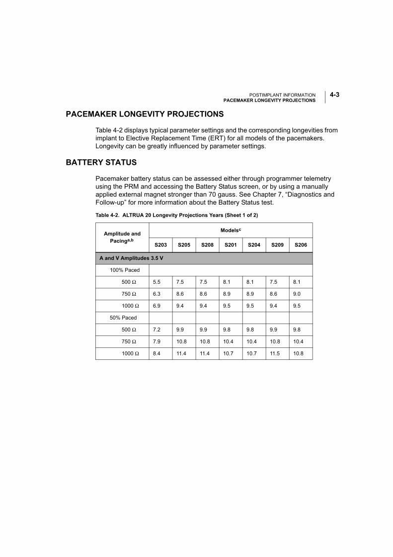
POSTIMPLANT INFORMATIONPACEMAKER LONGEVITY PROJECTIONS
4-3
PACEMAKER LONGEVITY PROJECTIONS
Table 4-2 displays typical parameter settings and the corresponding longevities from implant to Elective Replacement Time (ERT) for all models of the pacemakers. Longevity can be greatly influenced by parameter settings.
BATTERY STATUS
Pacemaker battery status can be assessed either through programmer telemetry using the PRM and accessing the Battery Status screen, or by using a manually applied external magnet stronger than 70 gauss. See Chapter 7, “Diagnostics and Follow-up” for more information about the Battery Status test.
Table 4-2. ALTRUA 20 Longevity Projections Years (Sheet 1 of 2)
Amplitude and Pacinga,b
Modelsc
S203 S205 S208 S201 S204 S209 S206
A and V Amplitudes 3.5 V
100% Paced
500 Ω 5.5 7.5 7.5 8.1 8.1 7.5 8.1
750 Ω 6.3 8.6 8.6 8.9 8.9 8.6 9.0
1000 Ω 6.9 9.4 9.4 9.5 9.5 9.4 9.5
50% Paced
500 Ω 7.2 9.9 9.9 9.8 9.8 9.9 9.8
750 Ω 7.9 10.8 10.8 10.4 10.4 10.8 10.4
1000 Ω 8.4 11.4 11.4 10.7 10.7 11.5 10.8
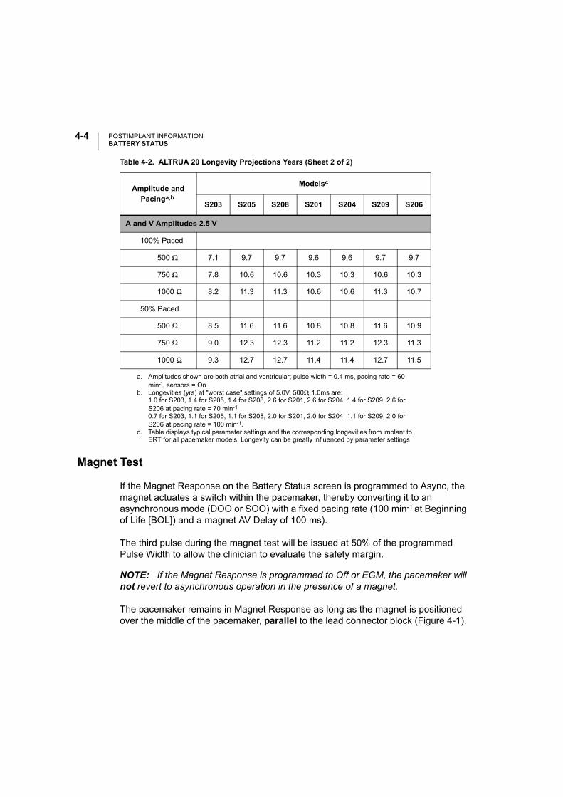
POSTIMPLANT INFORMATIONBATTERY STATUS
4-4
Magnet Test
If the Magnet Response on the Battery Status screen is programmed to Async, the magnet actuates a switch within the pacemaker, thereby converting it to an asynchronous mode (DOO or SOO) with a fixed pacing rate (100 min-¹ at Beginning of Life [BOL]) and a magnet AV Delay of 100 ms).
The third pulse during the magnet test will be issued at 50% of the programmed Pulse Width to allow the clinician to evaluate the safety margin.
NOTE: If the Magnet Response is programmed to Off or EGM, the pacemaker will not revert to asynchronous operation in the presence of a magnet.
The pacemaker remains in Magnet Response as long as the magnet is positioned over the middle of the pacemaker, parallel to the lead connector block (Figure 4-1).
A and V Amplitudes 2.5 V
100% Paced
500 Ω 7.1 9.7 9.7 9.6 9.6 9.7 9.7
750 Ω 7.8 10.6 10.6 10.3 10.3 10.6 10.3
1000 Ω 8.2 11.3 11.3 10.6 10.6 11.3 10.7
50% Paced
500 Ω 8.5 11.6 11.6 10.8 10.8 11.6 10.9
750 Ω 9.0 12.3 12.3 11.2 11.2 12.3 11.3
1000 Ω 9.3 12.7 12.7 11.4 11.4 12.7 11.5
a. Amplitudes shown are both atrial and ventricular; pulse width = 0.4 ms, pacing rate = 60 min-¹, sensors = On
b. Longevities (yrs) at "worst case" settings of 5.0V, 500Ω, 1.0ms are:1.0 for S203, 1.4 for S205, 1.4 for S208, 2.6 for S201, 2.6 for S204, 1.4 for S209, 2.6 for S206 at pacing rate = 70 min-1
0.7 for S203, 1.1 for S205, 1.1 for S208, 2.0 for S201, 2.0 for S204, 1.1 for S209, 2.0 for S206 at pacing rate = 100 min-1.
c. Table displays typical parameter settings and the corresponding longevities from implant to ERT for all pacemaker models. Longevity can be greatly influenced by parameter settings
Table 4-2. ALTRUA 20 Longevity Projections Years (Sheet 2 of 2)
Amplitude and Pacinga,b
Modelsc
S203 S205 S208 S201 S204 S209 S206
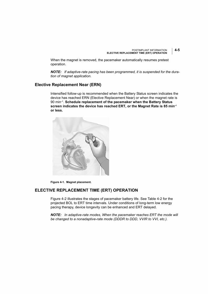
POSTIMPLANT INFORMATIONELECTIVE REPLACEMENT TIME (ERT) OPERATION
4-5
When the magnet is removed, the pacemaker automatically resumes pretest operation.
NOTE: If adaptive-rate pacing has been programmed, it is suspended for the dura-tion of magnet application.
Elective Replacement Near (ERN)
Intensified follow-up is recommended when the Battery Status screen indicates the device has reached ERN (Elective Replacement Near) or when the magnet rate is 90 min-¹. Schedule replacement of the pacemaker when the Battery Status screen indicates the device has reached ERT, or the Magnet Rate is 85 min-¹ or less.
Figure 4-1. Magnet placement.
ELECTIVE REPLACEMENT TIME (ERT) OPERATION
Figure 4-2 illustrates the stages of pacemaker battery life. See Table 4-2 for the projected BOL to ERT time intervals. Under conditions of long-term low energy pacing therapy, device longevity can be enhanced and ERT delayed.
NOTE: In adaptive-rate modes, When the pacemaker reaches ERT the mode will be changed to a nonadaptive-rate mode (DDDR to DDD, VVIR to VVI, etc.).
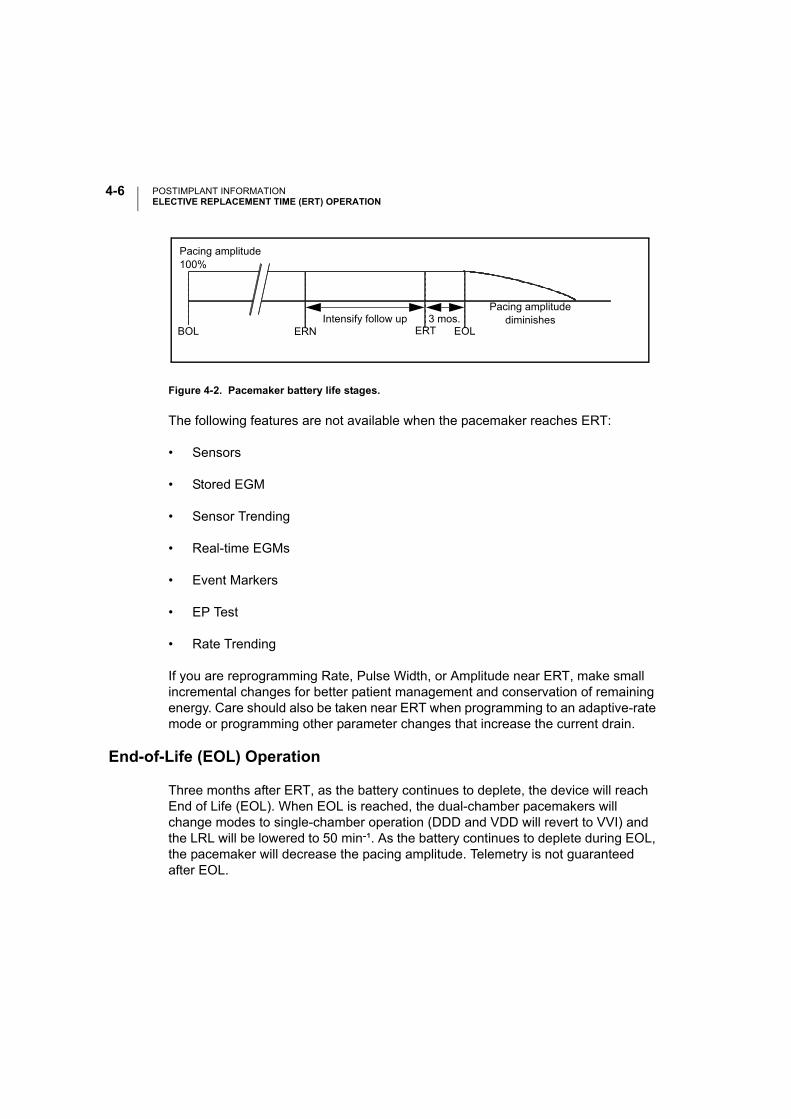
POSTIMPLANT INFORMATIONELECTIVE REPLACEMENT TIME (ERT) OPERATION
4-6
Figure 4-2. Pacemaker battery life stages.
The following features are not available when the pacemaker reaches ERT:
• Sensors
• Stored EGM
• Sensor Trending
• Real-time EGMs
• Event Markers
• EP Test
• Rate Trending
If you are reprogramming Rate, Pulse Width, or Amplitude near ERT, make small incremental changes for better patient management and conservation of remaining energy. Care should also be taken near ERT when programming to an adaptive-rate mode or programming other parameter changes that increase the current drain.
End-of-Life (EOL) Operation
Three months after ERT, as the battery continues to deplete, the device will reach End of Life (EOL). When EOL is reached, the dual-chamber pacemakers will change modes to single-chamber operation (DDD and VDD will revert to VVI) and the LRL will be lowered to 50 min-¹. As the battery continues to deplete during EOL, the pacemaker will decrease the pacing amplitude. Telemetry is not guaranteed after EOL.
BOL ERN ERT EOLIntensify follow up 3 mos.
Pacing amplitude diminishes
Pacing amplitude100%
POSTIMPLANT INFORMATIONEXPLANT INFORMATION
4-7
The following features are not available when the pacemaker reaches EOL:
• Dual-chamber (reverts to single-chamber)
• Temporary Parameters
• Safety Switch—the Lead Configuration remains at its pre-EOL value
• Rate Smoothing
• Search Hysteresis
• Arrhythmia Logbook
• Event Counters
• Histograms
• Quick Check
• Lead Impedance measurements—stored and interactive
• P and R-wave measurements—stored and interactive
• Semiautomatic Threshold Tests
EXPLANT INFORMATION
Return all explanted pacemakers and leads to Boston Scientific for analysis and disposal. Examination of explanted devices can provide information for continued improvement in device reliability and will permit calculation of any warranty replacement credit due.
CAUTIONS:
• Never incinerate a pacemaker because it can explode if subjected to incinera-tion or cremation temperatures; be sure that the pacemaker is explanted before a deceased patient is cremated.
• Do not implant an explanted pacemaker in another patient as sterility, function-ality, and reliability cannot be ensured.
POSTIMPLANT INFORMATIONIONIZING RADIATION
4-8
IONIZING RADIATION
Although most diagnostic radiation tools, including X-ray and fluoroscopy have not been problematic to the function of implanted pulse generators, therapeutic radiation procedures have interfered with device function and/or caused permanent damage to implanted pulse generators. Prior to a course of therapeutic radiation treatment, radiation oncologists should consult with the patient’s cardiologist or electrophysiologist to develop strategies specific to each patient for monitoring patient health and verifying appropriate pulse generator operation during and following radiating treatment sessions.
Considerations should include:
• Maximizing shielding of the pulse generator within the treatment field;
• Determining the appropriate level of patient monitoring during treatment; and
• Assessing pulse generator function during and following radiation treatment sessions.
Physicians should carefully consider all patient management options, including increased follow-up and device replacement, if warranted.
Pulse generator operation should be evaluated following radiation therapy to exercise as much device functionality as possible. The extent, timing, and frequency of this evaluation relative to the radiation therapy regimen are dependent upon current patient health, and therefore should be determined by the attending cardiologist and electrophysiologist. A thorough post therapy device follow-up includes:
• Interrogation of the pulse generator with a programmer
• Review of clinical events and fault codes.
• Review of Arrhythmia Logbook, including stored electrograms (EGMs).
• Review of real-time EGMs.
• Pacing threshold, intrinsic amplitude and lead impedance testing in all cham-bers.
POSTIMPLANT INFORMATIONWARRANTY INFORMATION
4-9
• Programming any Brady setting in permanent Brady parameters and then reprogramming it back to the desired value.
• Performing a Save All to Disk. (Only send the disk to Boston Scientific if abnor-malities are observed).
• Verification of appropriate final programming prior to allowing patient to leave the clinic.
Patient health may dictate the timing of post-therapy device evaluation activities (for example, timely verification of appropriate pacing is important for a pacer-dependant patient). If any abnormalities are observed during this evaluation, please contact Boston Scientific CRM Technical Services, which may request that the Save All to Disk results be returned.
The effects of radiation exposure on the implanted pulse generator may remain undetected until some time following exposure. For example, a malfunction due to radiation exposure may not be discovered until a device feature is activated several months after completion of a radiation treatment regimen. For this reason physicians should continue to monitor pulse generator function closely and use caution when programming a feature weeks or months post radiation therapy.
WARRANTY INFORMATION
A limited warranty certificate for the pulse generator is available. For a copy, contact Boston Scientific using the information on the back cover.

POSTIMPLANT INFORMATIONWARRANTY INFORMATION
4-10

5-1
USING THE PROGRAMMER / RECORDER / MONITOR (PRM)
CHAPTER 5
This chapter describes how to use the ZOOM LATITUDE Programming System, which includes the Model 3120 Programmer/Recorder/Monitor (PRM) and the Model 2892 CONSULT Software Application to communicate with the ALTRUA pacemakers. Refer to the PRM Operator’s Manual for full instructions.
The chapter is divided into three sections:
• Instructions for starting up the PRM and software application, and using the touchscreen and keys
• Introduction to software application terminology and how to move around the software application
• Instructions for communicating with the pacemaker (interrogating, program-ming, STAT PACE therapy delivery), and quitting a session
The terms used in this chapter will be used throughout the rest of this manual to describe how to change and program specific parameter settings. A clear understanding of interrogating and programming the pacemaker is important, as this information is not routinely repeated throughout the manual when specific functions are discussed.

USING THE PROGRAMMER / RECORDER / MONITOR (PRM)STARTING UP THE PRM AND SOFTWARE
5-2
STARTING UP THE PRM AND SOFTWARE
In this manual, the word “select” means to touch the stylus to the desired item on the screen. Use the stylus to activate the desired menu buttons and parameter selection buttons by touching and releasing the screen target. Touch the screen navigation buttons at the bottom of the screen to move from one screen to another.
NOTE: Use of the stylus is recommended for accuracy; however, touching the screen with your finger will also activate a selection.
A communication session may be started between the PRM and the pacemaker by performing the following steps. (The ZOOM LATITUDE Programming System Oper-ator’s Manual contains a complete description of the PRM.)
1. Connect the power cord to the PRM system and an outlet. (Refer to the PRM system operator’s manual for a complete description of the programmer.)
2. Raise the screen to a comfortable viewing angle.
3. Press the power switch to the On position.
4. Wait for the Boston Scientific startup screen (Figure 5-1) to appear.
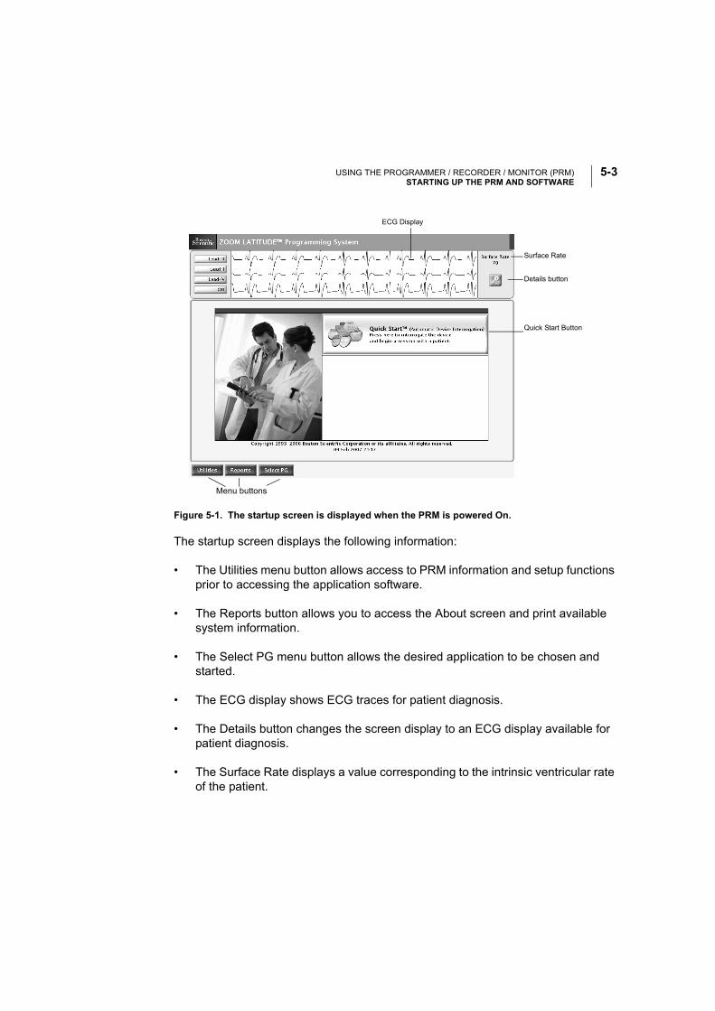
USING THE PROGRAMMER / RECORDER / MONITOR (PRM)STARTING UP THE PRM AND SOFTWARE
5-3
The startup screen displays the following information:
• The Utilities menu button allows access to PRM information and setup functions prior to accessing the application software.
• The Reports button allows you to access the About screen and print available system information.
• The Select PG menu button allows the desired application to be chosen and started.
• The ECG display shows ECG traces for patient diagnosis.
• The Details button changes the screen display to an ECG display available for patient diagnosis.
• The Surface Rate displays a value corresponding to the intrinsic ventricular rate of the patient.
Figure 5-1. The startup screen is displayed when the PRM is powered On.
Menu buttons
Details button
Surface Rate
Quick Start Button
ECG Display
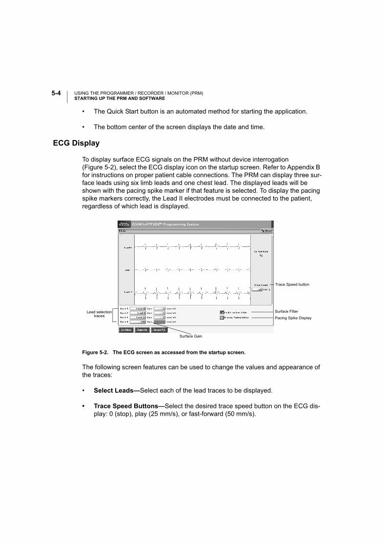
USING THE PROGRAMMER / RECORDER / MONITOR (PRM)STARTING UP THE PRM AND SOFTWARE
5-4
• The Quick Start button is an automated method for starting the application.
• The bottom center of the screen displays the date and time.
ECG Display
To display surface ECG signals on the PRM without device interrogation (Figure 5-2), select the ECG display icon on the startup screen. Refer to Appendix B for instructions on proper patient cable connections. The PRM can display three sur-face leads using six limb leads and one chest lead. The displayed leads will be shown with the pacing spike marker if that feature is selected. To display the pacing spike markers correctly, the Lead II electrodes must be connected to the patient, regardless of which lead is displayed.
Figure 5-2. The ECG screen as accessed from the startup screen.
The following screen features can be used to change the values and appearance of the traces:
• Select Leads—Select each of the lead traces to be displayed.
• Trace Speed Buttons—Select the desired trace speed button on the ECG dis-play: 0 (stop), play (25 mm/s), or fast-forward (50 mm/s).
Lead selectiontraces
Trace Speed button
Surface Gain
Surface Filter
Pacing Spike Display
USING THE PROGRAMMER / RECORDER / MONITOR (PRM)STARTING UP THE PRM AND SOFTWARE
5-5
• Printed Surface Gain—Adjust the Surface Gain of the traces that are captured on printouts by selecting the appropriate value.
• Surface Filter—Select the Filter On setting to minimize noise on the surface ECG. The Filter Off setting allows viewing surface ECGs with diagnostic filter settings.
• Pacing Spike Display—Program this feature On to show detected pacing spikes, shown by a marker on the top waveform.
To display a calibration pulse on the PRM, press the key labeled . Press the key labeled to force the surface trace back to baseline. To print the surface ECG on the PRM printer/recorder, select the desired speed key (10, 25, 50, or 100 mm/sec) on the printer/recorder. To stop the printer/recorder, press the speed key labeled 0 (zero).
Printing to an External Recorder
To view the surface ECG traces on an external recorder, press the desired speed key on the external recorder while the traces are displayed on the PRM screen. See Appendix B for instructions on connecting the PRM to the external recorder. Refer to the manual for the external recorder for instructions specific to its operation.
Quick Start
To automatically identify and interrogate the implanted pacemaker, place the telem-etry wand over the pacemaker and select the Quick Start button. A window indicat-ing one of the following conditions will appear, based on the implanted device:
• Application Startup in Progress—If the software for the implanted device is installed on the PRM, the PRM will identify the device, open the correct applica-tion, and automatically interrogate the pacemaker.
• Software Not Installed—If the software application for the implanted device is available for the PRM but not installed on it, a message window will appear identifying the device and stating that the software is not installed on the PRM.
• Software Not Available on PRM—If an older model device is identified that is only supported by an older model PRM, a message window will appear inform-ing the user that he or she must use a Model 2035 or Model 2901 PRM to inter-rogate and/or program the device.

USING THE PROGRAMMER / RECORDER / MONITOR (PRM)STARTING UP THE PRM AND SOFTWARE
5-6
• PG Not Identified—If a non-supported pulse generator is implanted, a mes-sage window will appear notifying the user that either the wand is out of range, there is telemetry noise, or the device is not identified.
To access the Demo mode, use the Select PG button at the top of the screen to choose the pacemaker family instead of using the Quick Start button.
The Utilities Menu on the Startup Screen
Before accessing the pacemaker software application, you may select the Utilities menu to access language selections, PRM information and clock and disk functions. To view or change the values, select the appropriate function from the Utilities menu.
The About Utility
The About utility screen lists the versions of the system software and the applica-tions available on the PRM, and provides the means to set or change the institution name and print the application revision information. To return to the startup screen, select the Close button.
Select the Institution field to update the institution name. If the PRM has been moved to a different institution, the name of the institution as it appears on the About screen can be changed prior to accessing the application software. The institution name also is displayed in the heading of printed reports.
After selecting the Institution field, a graphic keyboard (Figure 5-3 on page 5-7) together with the name of the institution will appear. Select the Clear button to remove the institution name from the graphic keyboard. Alternatively, one letter of the name can be deleted at a time by selecting the left arrow key on the graphic key-board. Each time the left arrow is selected, a character will be deleted in the box. Delete all the undesired characters.
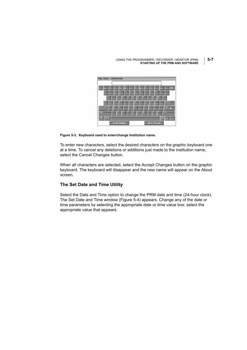
USING THE PROGRAMMER / RECORDER / MONITOR (PRM)STARTING UP THE PRM AND SOFTWARE
5-7
Figure 5-3. Keyboard used to enter/change Institution name.
To enter new characters, select the desired characters on the graphic keyboard one at a time. To cancel any deletions or additions just made to the institution name, select the Cancel Changes button.
When all characters are selected, select the Accept Changes button on the graphic keyboard. The keyboard will disappear and the new name will appear on the About screen.
The Set Date and Time Utility
Select the Date and Time option to change the PRM date and time (24-hour clock). The Set Date and Time window (Figure 5-4) appears. Change any of the date or time parameters by selecting the appropriate date or time value box; select the appropriate value that appears.
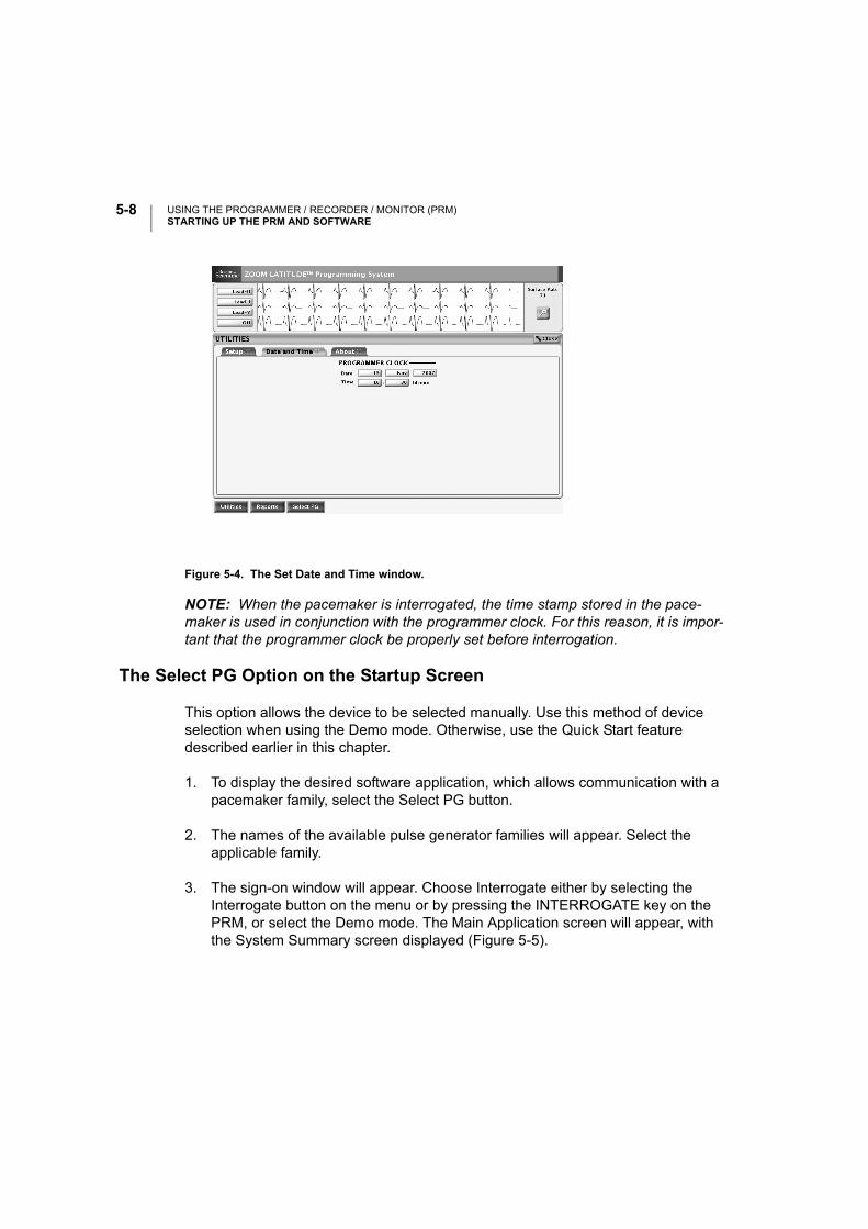
USING THE PROGRAMMER / RECORDER / MONITOR (PRM)STARTING UP THE PRM AND SOFTWARE
5-8
Figure 5-4. The Set Date and Time window.
NOTE: When the pacemaker is interrogated, the time stamp stored in the pace-maker is used in conjunction with the programmer clock. For this reason, it is impor-tant that the programmer clock be properly set before interrogation.
The Select PG Option on the Startup Screen
This option allows the device to be selected manually. Use this method of device selection when using the Demo mode. Otherwise, use the Quick Start feature described earlier in this chapter.
1. To display the desired software application, which allows communication with a pacemaker family, select the Select PG button.
2. The names of the available pulse generator families will appear. Select the applicable family.
3. The sign-on window will appear. Choose Interrogate either by selecting the Interrogate button on the menu or by pressing the INTERROGATE key on the PRM, or select the Demo mode. The Main Application screen will appear, with the System Summary screen displayed (Figure 5-5).
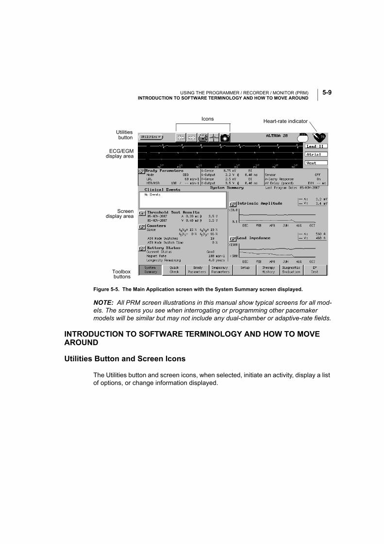
USING THE PROGRAMMER / RECORDER / MONITOR (PRM)INTRODUCTION TO SOFTWARE TERMINOLOGY AND HOW TO MOVE AROUND
5-9
Figure 5-5. The Main Application screen with the System Summary screen displayed.
NOTE: All PRM screen illustrations in this manual show typical screens for all mod-els. The screens you see when interrogating or programming other pacemaker models will be similar but may not include any dual-chamber or adaptive-rate fields.
INTRODUCTION TO SOFTWARE TERMINOLOGY AND HOW TO MOVE AROUND
Utilities Button and Screen Icons
The Utilities button and screen icons, when selected, initiate an activity, display a list of options, or change information displayed.
buttonUtilities
Toolboxbuttons
ECG/EGMdisplay area
Screendisplay area
Icons Heart-rate indicator
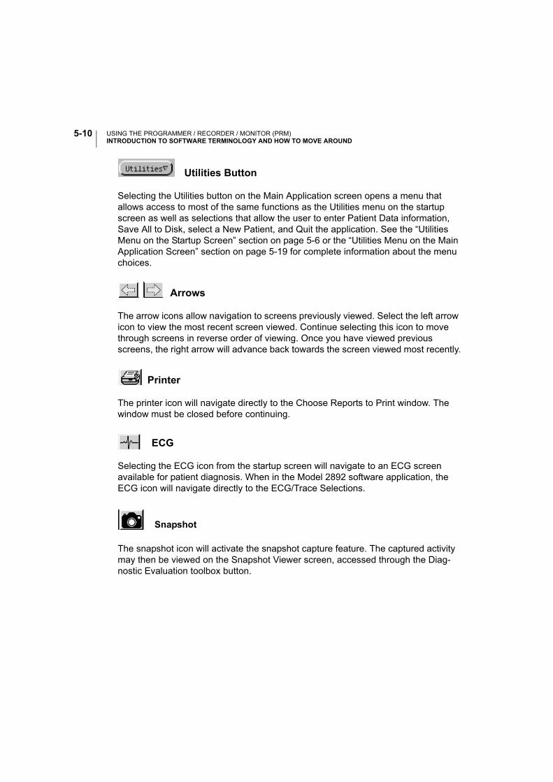
USING THE PROGRAMMER / RECORDER / MONITOR (PRM)INTRODUCTION TO SOFTWARE TERMINOLOGY AND HOW TO MOVE AROUND
5-10
Utilities Button
Selecting the Utilities button on the Main Application screen opens a menu that allows access to most of the same functions as the Utilities menu on the startup screen as well as selections that allow the user to enter Patient Data information, Save All to Disk, select a New Patient, and Quit the application. See the “Utilities Menu on the Startup Screen” section on page 5-6 or the “Utilities Menu on the Main Application Screen” section on page 5-19 for complete information about the menu choices.
Arrows
The arrow icons allow navigation to screens previously viewed. Select the left arrow icon to view the most recent screen viewed. Continue selecting this icon to move through screens in reverse order of viewing. Once you have viewed previous screens, the right arrow will advance back towards the screen viewed most recently.
Printer
The printer icon will navigate directly to the Choose Reports to Print window. The window must be closed before continuing.
ECG
Selecting the ECG icon from the startup screen will navigate to an ECG screen available for patient diagnosis. When in the Model 2892 software application, the ECG icon will navigate directly to the ECG/Trace Selections.
Snapshot
The snapshot icon will activate the snapshot capture feature. The captured activity may then be viewed on the Snapshot Viewer screen, accessed through the Diag-nostic Evaluation toolbox button.
USING THE PROGRAMMER / RECORDER / MONITOR (PRM)INTRODUCTION TO SOFTWARE TERMINOLOGY AND HOW TO MOVE AROUND
5-11
Information (Parameter Interaction Warning)
When a new parameter is entered into the Change column of a screen, it is immedi-ately checked for interactions with other parameters. The exclamation point icon indicates that a Parameter Interaction warning is present. Whenever a parameter is changed in such a way that additional information needs to be presented to the clini-cian, this icon can be selected to view the information. Changes to the affected parameter(s) need not be made to proceed with the patient session; however, physi-cian discretion is advised depending on the type of patient or other circumstances before proceeding. Changes to the affected parameters can be made directly from the Parameter Interaction window.
Stop Sign (Parameter Interaction)
When a new parameter value is entered in the Change column of a screen, it is immediately checked for interactions with other parameters. If the new value vio-lates interactive limits within the application, a stop sign icon will appear at the top of the display, indicating a Parameter Interaction error. Select this icon to access the Parameter Interaction screen to view the error and its suggested resolution. A cor-rection to the affected parameter must be made in order to proceed with program-ming changes and can be made directly from the Parameter Interaction window. When changing the setting of several parameters, the clinician might not wish to select the Parameter Interaction icon immediately, as subsequent changes could eliminate the interaction.
Stop Sign in the System Summary Screen (Clinical Event)
If an important event has occurred since the last follow-up, a stop sign icon will appear in the System Summary screen. Selecting the stop sign button or its associ-ated text opens a window or navigates to a screen containing information about the event.
Shortcut
In the screen display area, select the shortcut icon to go directly from the parameter, feature, or associated event to the screen that provides detailed information. Use the left arrow button to return to the original screen.
USING THE PROGRAMMER / RECORDER / MONITOR (PRM)INTRODUCTION TO SOFTWARE TERMINOLOGY AND HOW TO MOVE AROUND
5-12
Magnifying Glass
In the screen display area, select the magnifying glass icon to open a window that displays more detailed information about a parameter, feature, or event. The win-dow must be closed before continuing.
Check Box
In the screen display area, a check in a box indicates that the function or activity will be active. Select a box containing a check to clear the check and deactivate the function or activity.
Go
Select a Go icon to initiate any test on the Quick Check screen.
Logos
Demo
This logo is displayed when the application is initially accessed without interrogating a pacemaker or reading a disk. This allows familiarization with the software without having to interact with a pacemaker.
Pacemaker
This logo is displayed when a pacemaker has been interrogated.
Heart Rate Indicator
The heart rate logo displays the heart rate from the ECG.

USING THE PROGRAMMER / RECORDER / MONITOR (PRM)INTRODUCTION TO SOFTWARE TERMINOLOGY AND HOW TO MOVE AROUND
5-13
ECG/EGM Display
This display shows real-time surface ECG traces, intracardiac EGMs, and event markers. See Chapter 8, “Electrograms (EGMs)/Event Markers/Reports” for details.
Toolbox Buttons
The toolbox determines which screen is displayed, depending on the chosen tool-box button. The screens allow interaction with the pacemaker as well as a review of diagnostic data in pacemaker memory. Only one tool can be selected at a time.
General Window Functions
Windows contain information relevant to a particular function and include names of pacemaker parameters and functions, value boxes to accommodate value changes, buttons to open additional windows, and buttons to Cancel Changes or Close the window. To remove the window from the display, select the Close or Cancel button.
How to Move a Window
To accommodate viewing of multiple open windows, the windows can be moved to another location on the screen using the touchscreen stylus.
1. Position the stylus within the title bar at the top of the window.
2. An outline appears around the window to indicate the window can be moved. While touching the stylus to the window outline, drag the window to the desired location.
3. Lift the stylus when the outline is in the desired location. The window will move to and remain in that location until it is moved again, or until the window is closed.
Message Window
Message windows (Figure 5-6) may appear during a communication session. Some require action before continuing the session, while others simply relay information without requiring further action. The messages indicate the required action, if any.
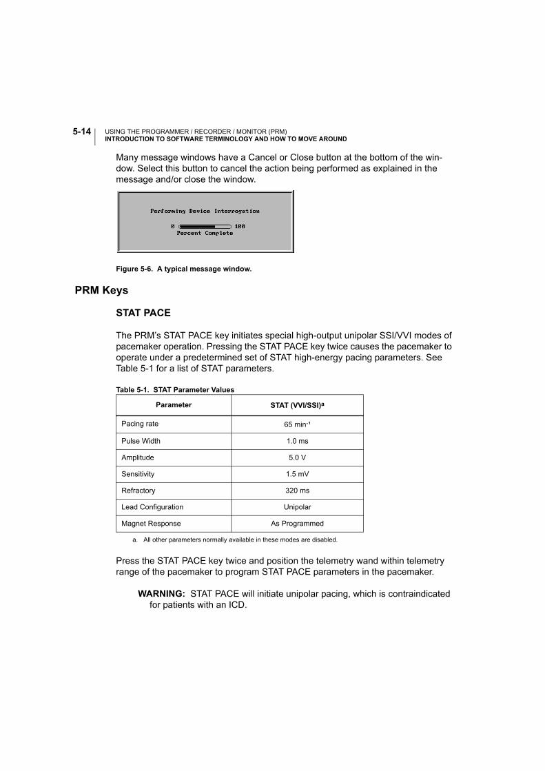
USING THE PROGRAMMER / RECORDER / MONITOR (PRM)INTRODUCTION TO SOFTWARE TERMINOLOGY AND HOW TO MOVE AROUND
5-14
Many message windows have a Cancel or Close button at the bottom of the win-dow. Select this button to cancel the action being performed as explained in the message and/or close the window.
Figure 5-6. A typical message window.
PRM Keys
STAT PACE
The PRM’s STAT PACE key initiates special high-output unipolar SSI/VVI modes of pacemaker operation. Pressing the STAT PACE key twice causes the pacemaker to operate under a predetermined set of STAT high-energy pacing parameters. See Table 5-1 for a list of STAT parameters.
Table 5-1. STAT Parameter Values
Press the STAT PACE key twice and position the telemetry wand within telemetry range of the pacemaker to program STAT PACE parameters in the pacemaker.
WARNING: STAT PACE will initiate unipolar pacing, which is contraindicated for patients with an ICD.
Parameter STAT (VVI/SSI)a
a. All other parameters normally available in these modes are disabled.
Pacing rate 65 min-¹
Pulse Width 1.0 ms
Amplitude 5.0 V
Sensitivity 1.5 mV
Refractory 320 ms
Lead Configuration Unipolar
Magnet Response As Programmed
USING THE PROGRAMMER / RECORDER / MONITOR (PRM)PROGRAMMING AND INTERROGATION
5-15
CAUTION: If the pacemaker is not reprogrammed, it will continue to pace in SSI mode at the high-energy STAT values. You might wish to reprogram the pacemaker to other parameter settings for alternative patient therapies or to extend pacemaker longevity.
NOTE: Exit STAT by programming new Brady Parameters.
PROGRAM and INTERROGATE
These keys are discussed in “Programming and Interrogation” below.
DIVERT THERAPY and STAT SHOCK
The DIVERT THERAPY and STAT SHOCK keys are not applicable within the Model 2892 software application.
PROGRAMMING AND INTERROGATION
The ALTRUA pacemakers are programmed through noninvasive RF telemetry using the Boston Scientific Model 3120 PRM equipped with the Model 2892 CONSULT Software Application and a Model 6577 Sterilized Telemetry Wand.
During a programming sequence, the telemetry wand is positioned over the pace-maker. Allow all telemetry sequences to complete before removing the wand. The sequence is complete when the scale in the message window reaches 100% and the message window closes.
Interrogation is accomplished in a similar fashion. If a permanent record of interro-gated data is desired, the PRM can provide printed reports that include such infor-mation as present parameter values, therapy history data, pacemaker battery status, and programmed patient data that has been entered (e.g., date of implant, lead type, patient indications).
Establishing Telemetry Communication
Telemetry communication is required to direct the INTERROGATE, PROGRAM, and STAT PACE commands on the PRM, which are described in this chapter. Telemetry communication also is required to perform other features such as Lead Impedance and Threshold Tests, described in later chapters.
A communication session with the PRM can be established by performing the fol-lowing steps:
USING THE PROGRAMMER / RECORDER / MONITOR (PRM)PROGRAMMING AND INTERROGATION
5-16
1. Connect the telemetry wand to the PRM.
2. Position the wand over the pacemaker.
3. Direct a command from the PRM to the pacemaker (e.g., INTERROGATE or PROGRAM).
NOTE: Status windows might appear on the screen during a communication ses-sion to indicate that the pacemaker is out of range. Reposition the wand to reestab-lish communication or try turning the telemetry wand over. (When event markers or intracardiac EGMs are activated, a message will not appear, but the event marker or intracardiac EGMs transmission will be interrupted until telemetry is restored.)
Interrogating the Pacemaker
Pacemaker interrogation is the first step in any follow-up session. An initial interro-gation retrieves the following information from pacemaker memory: parameter set-tings, patient data, and battery status. When the Quick Start button is selected on the startup window, the PRM will identify the device, open the correct application, and automatically interrogate the pacemaker.
Use the following procedure to interrogate the pacemaker, if the Quick Start feature is not used:
1. To initially interrogate the pacemaker, select the Interrogate button on the sign-on screen (or the INTERROGATE key on the PRM). To perform interroga-tions during a session, press the INTERROGATE key on the PRM panel while in the Brady Parameters screen. A message window will appear.
2. Position the telemetry wand over the pacemaker. The scale in the message win-dow will indicate the progression of the interrogation.
3. Maintain the telemetry link until the scale indicates that the interrogation has reached 100% completion and the message window disappears.
Prematurely moving the wand away from the pacemaker during the interroga-tion sequence causes a message to appear, indicating that there is telemetry noise or that the wand has been moved out of telemetry range. Reestablish telemetry communication to continue the interrogation sequence. If communica-tion cannot be reestablished, select Cancel in the message window to stop the interrogation sequence.
USING THE PROGRAMMER / RECORDER / MONITOR (PRM)PROGRAMMING AND INTERROGATION
5-17
CAUTION: Computerized systems can be subject to electrical interference, or “noise.” In the presence of such interference, telemetry communication is inter-rupted and prevents improper interrogation or programming. If the message window appears indicating that the wand is out of range or there is telemetry noise, move the PRM away from such electrical devices as electrosurgical and monitoring equipment and ensure that the wand cord and cables are not cross-ing one another. Telemetry communication will resume when the noise source is removed. The message window also has a Cancel button that, when selected, will stop the interrogation.
Changing Parameter Values
The parameter values are changed by touching the stylus to the appropriate param-eter box in the Change column and lifting the stylus from the screen. When changes have been made to parameter values, the data appear in the Change box until pro-grammed into the pacemaker. Use one of the following methods to select the desired value, according to the window that appears:
• Palette Window—Touch the desired value and lift the stylus; it will be selected and will appear in the Change column parameter box.
• Keyboard Window—Touch the first character of the new value; it will appear in the data entry box. Continue until the entire new entry appears. Alternatively, one character can be deleted at a time by selecting the left arrow key on the graphic keyboard. Each time the left arrow is selected, a character will be deleted in the box. Delete all the undesired characters. To cancel any deletions or additions just made, select the Cancel Changes button. When all characters are selected, select the Close button on the graphic keyboard.
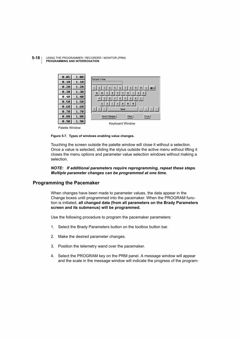
USING THE PROGRAMMER / RECORDER / MONITOR (PRM)PROGRAMMING AND INTERROGATION
5-18
Touching the screen outside the palette window will close it without a selection. Once a value is selected, sliding the stylus outside the active menu without lifting it closes the menu options and parameter value selection windows without making a selection.
NOTE: If additional parameters require reprogramming, repeat these steps. Multiple parameter changes can be programmed at one time.
Programming the Pacemaker
When changes have been made to parameter values, the data appear in the Change boxes until programmed into the pacemaker. When the PROGRAM func-tion is initiated, all changed data (from all parameters on the Brady Parameters screen and its submenus) will be programmed.
Use the following procedure to program the pacemaker parameters:
1. Select the Brady Parameters button on the toolbox button bar.
2. Make the desired parameter changes.
3. Position the telemetry wand over the pacemaker.
4. Select the PROGRAM key on the PRM panel. A message window will appear and the scale in the message window will indicate the progress of the program-
Figure 5-7. Types of windows enabling value changes.
Palette WindowKeyboard Window
USING THE PROGRAMMER / RECORDER / MONITOR (PRM)THE UTILITIES MENU ON THE MAIN APPLICATION SCREEN
5-19
ming. If a sensor is being enabled or disabled, a second message window will indicate that Trending Setup is occurring.
5. Maintain the telemetry link until the scale indicates that the programming has reached 100% completion and the message window disappears. Prematurely moving the wand away from the pacemaker during the programming sequence causes a message to appear, indicating that there is telemetry noise, or that the wand has been moved out of telemetry range. Reestablish telemetry communi-cation to continue the programming sequence. If communication cannot be reestablished or if you wish to halt the sequence, select Cancel in the message window to stop the programming sequence. Allow the cancel sequences to complete before removing the telemetry wand. The sequence is complete when the scale in the message window reaches 100% and the message window closes.
THE UTILITIES MENU ON THE MAIN APPLICATION SCREEN
The Utilities menu button at the top of the screen will allow you to access any of the following functions described below. Many of these functions also are available from the Utilities menu on the startup screen, and are described in detail in that section earlier in this chapter.
Patient Data
Important information about the implant and about the patient can be stored in the pacemaker for future reference and viewed on the Patient Data window. The infor-mation can be accessed at any time using normal interrogation procedures. Except for the lead type, this information does not affect the operation of the pacemaker. If a unipolar lead type is selected, the pacing and/or sensing configurations cannot be programmed to Bipolar. See “Bipolar Configuration Lock-out” on page 6-41 for more information.
The pacemaker model number and serial number are retrieved directly from the pacemaker and cannot be modified by the clinician.
Use the following procedure to make changes to the patient data stored in the pacemaker:
1. Select Patient Data from the Utilities menu at the top of the screen.

USING THE PROGRAMMER / RECORDER / MONITOR (PRM)THE UTILITIES MENU ON THE MAIN APPLICATION SCREEN
5-20
2. Touch the stylus to the parameter that you want to change. Depending on the parameter type, a numeric palette, a menu, or the graphical keyboard will be displayed.
3. Make the necessary modifications to the parameter value.
4. To store the data to the pacemaker, select Store Data. The new information will be stored in the pacemaker’s internal memory.
Save All to Disk
When a Model 6627 patient data disk is inserted in the disk drive of the PRM, the following data can be saved:
• Brady Parameters
• Patient Data
• Intrinsic Amplitude test results
• Lead Impedance test results
• Threshold test results
• Battery Status
• Arrhythmia Logbook
• Histograms/Counters
NOTE: Data stored on this disk cannot be read using the PRM.
1. Insert a new patient data disk into the disk drive of the PRM.
NOTE: The write-protect tab on the disk should be in the closed position (black tab covering the hole) when saving data to the disk.
2. Select the Save All To Disk option from the Utilities menu.
3. When the data have been saved on the disk, remove the disk from the drive and write the name of the patient on the disk label. (If multiple disks are used to save all the data for one patient, number the disks sequentially or write the date that the information was saved.)
NOTES:
• If you insert a patient data disk containing data downloaded using a program-mer other than the Model 3120 PRM, a message will appear indicating the disk
USING THE PROGRAMMER / RECORDER / MONITOR (PRM)THE UTILITIES MENU ON THE MAIN APPLICATION SCREEN
5-21
is incompatible. If you reformat the patient data disk for use on the Model 3120 PRM, any data on the disk will be lost.
• Refer to the ZOOM LATITUDE Programming System Operator’s Manual for care instructions for data disks.
Copy Disk
This feature is available to make duplicate copies of a Model 6627 Patient Data Disk.
1. Select the Copy Disk option from the Utilities menu. A message will appear instructing the user to insert the source disk.
2. Insert into the disk drive of the PRM the disk that contains the information to be copied (the source disk) and select the Read Disk button. The PRM will read the information from the disk. When completed, a message will appear indicating that a new disk (the destination disk) should be inserted.
3. Insert a new patient data disk and select the Write Disk button. (Do not use a disk that contains other patient data, as the existing data would be lost.) The information will be copied onto the new disk. Write the patient name on the disk label.
CAUTION: Make sure the disk drive light is off before removing the patient data disk from the disk drive. Removing the disk while the drive heads are engaged can damage the disk and/or the drive.
Format Disk
This feature is available for erasing data from and reformatting a patient data disk.
1. Insert a patient data disk into the disk drive of the PRM.
2. Select the Format Disk option from the Utilities menu. Formatting a disk will remove all data from the disk.
3. When formatting is complete, insert another disk and select the Format Another Disk button or select the Cancel button to exit the format feature.
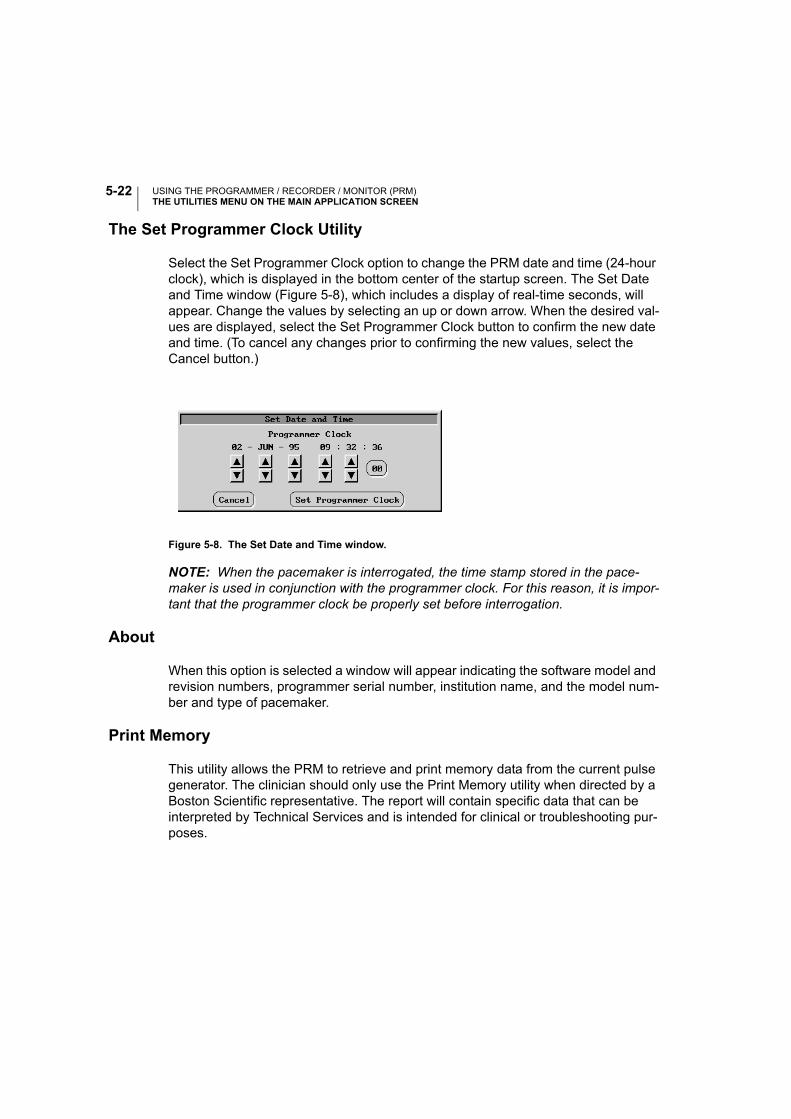
USING THE PROGRAMMER / RECORDER / MONITOR (PRM)THE UTILITIES MENU ON THE MAIN APPLICATION SCREEN
5-22
The Set Programmer Clock Utility
Select the Set Programmer Clock option to change the PRM date and time (24-hour clock), which is displayed in the bottom center of the startup screen. The Set Date and Time window (Figure 5-8), which includes a display of real-time seconds, will appear. Change the values by selecting an up or down arrow. When the desired val-ues are displayed, select the Set Programmer Clock button to confirm the new date and time. (To cancel any changes prior to confirming the new values, select the Cancel button.)
Figure 5-8. The Set Date and Time window.
NOTE: When the pacemaker is interrogated, the time stamp stored in the pace-maker is used in conjunction with the programmer clock. For this reason, it is impor-tant that the programmer clock be properly set before interrogation.
About
When this option is selected a window will appear indicating the software model and revision numbers, programmer serial number, institution name, and the model num-ber and type of pacemaker.
Print Memory
This utility allows the PRM to retrieve and print memory data from the current pulse generator. The clinician should only use the Print Memory utility when directed by a Boston Scientific representative. The report will contain specific data that can be interpreted by Technical Services and is intended for clinical or troubleshooting pur-poses.

USING THE PROGRAMMER / RECORDER / MONITOR (PRM)THE UTILITIES MENU ON THE MAIN APPLICATION SCREEN
5-23
New Patient
The Utilities menu offers a New Patient option that ends a current patient session and allows a different device to be interrogated without having to exit the Model 2892 software application. If a second device is interrogated without ending a previous session, a message will appear indicating that the wrong pacemaker was identified. Use the following steps to start a follow-up procedure for a new patient:
Select the Utilities menu from the Main Application screen.
1. Highlight and select the New Patient option. A message window will appear indi-cating that selecting Confirm for new patient will restart the Model 2892 applica-tion and that all session data will be lost.
NOTE: If reports are being printed, the Cancel Printing button must be selected before the Confirm button can be selected.
2. Select the Confirm button. (Selecting the Close button will remove the message window and retain the current patient session.) The current session will end, the sign-on screen will be displayed, and the options to Interrogate, or Quit, or access the Demo mode will be available.
Quit
The Utilities menu offers a Quit option that ends the current session, exits the soft-ware application, and returns to the startup screen.
1. Select the Utilities menu from the Main Application window.
2. Highlight and select the Quit option. The message will appear indicating that selecting Quit will exit the application and return to the startup screen.
NOTE: If reports are being printed, the Cancel Printing button must be selected before the Quit button can be selected.
3. Select the Quit button to end the session. (Selecting the Close button will remove the message window and retain the current patient session.)

USING THE PROGRAMMER / RECORDER / MONITOR (PRM)THE UTILITIES MENU ON THE MAIN APPLICATION SCREEN
5-24
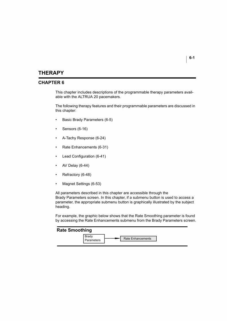
6-1
THERAPY
CHAPTER 6
This chapter includes descriptions of the programmable therapy parameters avail-able with the ALTRUA 20 pacemakers.
The following therapy features and their programmable parameters are discussed in this chapter:
• Basic Brady Parameters (6-5)
• Sensors (6-16)
• A-Tachy Response (6-24)
• Rate Enhancements (6-31)
• Lead Configuration (6-41)
• AV Delay (6-44)
• Refractory (6-48)
• Magnet Settings (6-53)
All parameters described in this chapter are accessible through the Brady Parameters screen. In this chapter, if a submenu button is used to access a parameter, the appropriate submenu button is graphically illustrated by the subject heading.
For example, the graphic below shows that the Rate Smoothing parameter is found by accessing the Rate Enhancements submenu from the Brady Parameters screen.
Rate SmoothingBrady Parameters Rate Enhancements
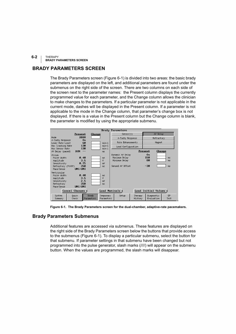
THERAPYBRADY PARAMETERS SCREEN
6-2
BRADY PARAMETERS SCREEN
The Brady Parameters screen (Figure 6-1) is divided into two areas: the basic brady parameters are displayed on the left, and additional parameters are found under the submenus on the right side of the screen. There are two columns on each side of the screen next to the parameter names: the Present column displays the currently programmed value for each parameter, and the Change column allows the clinician to make changes to the parameters. If a particular parameter is not applicable in the current mode, dashes will be displayed in the Present column. If a parameter is not applicable to the mode in the Change column, that parameter’s change box is not displayed. If there is a value in the Present column but the Change column is blank, the parameter is modified by using the appropriate submenu.
Figure 6-1. The Brady Parameters screen for the dual-chamber, adaptive-rate pacemakers.
Brady Parameters Submenus
Additional features are accessed via submenus. These features are displayed on the right side of the Brady Parameters screen below the buttons that provide access to the submenus (Figure 6-1). To display a particular submenu, select the button for that submenu. If parameter settings in that submenu have been changed but not programmed into the pulse generator, slash marks (////) will appear on the submenu button. When the values are programmed, the slash marks will disappear.

THERAPYBRADY PARAMETERS SCREEN
6-3
As with the basic Brady Parameters, availability of the submenu parameters is dependent on the selected mode. If a particular parameter is not applicable to the mode displayed at the top of the Present column, the parameter line will display dashes. If a parameter is not applicable to the mode in the Change column, that parameter’s change box is not displayed.
Modifying Parameter Values
Use the following procedure to make changes to the permanent pacing parameters:
1. Select the Brady Parameters toolbox button.
2. Select the parameter to change by touching the Change box next to the parameter.
3. Select new parameter values by increasing or decreasing values in the Change column. If additional parameters require reprogramming, repeat to achieve the desired values. Multiple parameter changes can be programmed at one time.
After the change(s) has been entered, make sure that the or icon is not displayed at the top of the screen. If it is, select that icon to determine how the current changes violate interactive limits. The stop sign indicates an error that must be corrected before programming can occur; warnings, indicated by the exclamation mark, should be carefully considered before continuing.
4. Press the PROGRAM key to program the changes in the pacemaker via telem-etry. These parameters now become the permanent pacing parameters and are listed in the Present column.
The Cancel Changes Button
The Cancel Changes button can be selected to delete the values from the Change column before they are programmed.
The Load Nominals Button
Selecting this button will place the nominal values of the pacemaker, except for nominal Lead Configuration, in the Change column; press the PROGRAM key to program the changes in the pacemaker via telemetry. These parameters now become the permanent pacing parameters and are listed in the Present column. Lead Configuration will remain as originally programmed.

THERAPYBRADY PARAMETERS SCREEN
6-4
The Load Initial Values Button
At the start of a patient session, when the pacemaker is initially interrogated, the currently programmed values are displayed on the PRM screen and are referred to as the initial values. At any time during the patient session, the initial values can be reloaded by selecting this button if values have been changed. The values will be visible in the Change column; press the PROGRAM key to program the changes in the pacemaker via telemetry. These parameters now become the permanent pacing parameters and are listed in the Present column.
Load Initial Values is particularly helpful when mode changes have been made dur-ing a programming session because it ensures that all programmable settings, including lead polarity, are returned to initial values.

THERAPYBASIC BRADY PARAMETERS—MODE
6-5
BASIC BRADY PARAMETERS—
This subchapter discusses the basic parameters appearing on the left half of the PRM Brady Parameters screen. Each parameter is described, and the programma-ble values are listed.
MODE
The pacemakers can be programmed to the following modes, depending on the model. For a complete discussion of each of these modes, see Appendix A.
min-¹
Brady Parameters Brady ParametersPARAMETER PRESENT CHANGE
ModeA-Tachy Response
Max Tracking Rate
AmplitudeSensitivityRefractory(PVARP)
Pulse WidthAmplitudeSensitivityRefractory
Atrial
Ventricular
AV Delay (paced)
min-¹
ms
msVmVms
msVmVms
Max Sensor Rate
min-¹
Pulse Width
DDD
60130---DYN --
0.403.50.75250
0.403.52.5250
Lower Rate Limit
Pace/Sense
Pace/Sense
On
UNI/UNI
UNI/UNI
Programmable Values: Refer to Table 6-1 for modes available for each model.
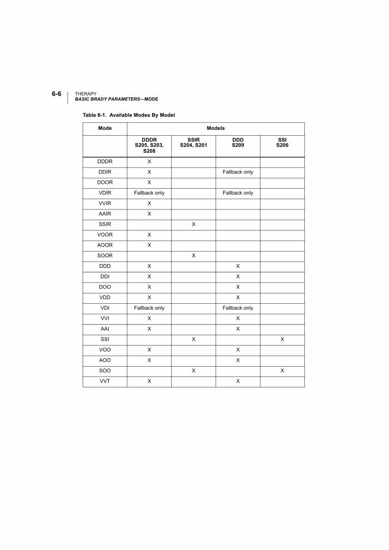
THERAPYBASIC BRADY PARAMETERS—MODE
6-6
Table 6-1. Available Modes By Model
Mode Models
DDDRS205, S203,
S208
SSIRS204, S201
DDDS209
SSIS206
DDDR X
DDIR X Fallback only
DOOR X
VDIR Fallback only Fallback only
VVIR X
AAIR X
SSIR X
VOOR X
AOOR X
SOOR X
DDD X X
DDI X X
DOO X X
VDD X X
VDI Fallback only Fallback only
VVI X X
AAI X X
SSI X X
VOO X X
AOO X X
SOO X X
VVT X X
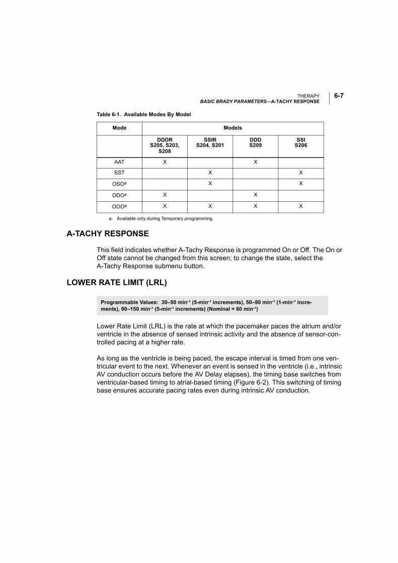
THERAPYBASIC BRADY PARAMETERS—A-TACHY RESPONSE
6-7
A-TACHY RESPONSE
This field indicates whether A-Tachy Response is programmed On or Off. The On or Off state cannot be changed from this screen; to change the state, select the A-Tachy Response submenu button.
LOWER RATE LIMIT (LRL)
Lower Rate Limit (LRL) is the rate at which the pacemaker paces the atrium and/or ventricle in the absence of sensed intrinsic activity and the absence of sensor-con-trolled pacing at a higher rate.
As long as the ventricle is being paced, the escape interval is timed from one ven-tricular event to the next. Whenever an event is sensed in the ventricle (i.e., intrinsic AV conduction occurs before the AV Delay elapses), the timing base switches from ventricular-based timing to atrial-based timing (Figure 6-2). This switching of timing base ensures accurate pacing rates even during intrinsic AV conduction.
AAT X X
SST X X
OSOa X X
ODOa X X
OOOa X X X X
a. Available only during Temporary programming.
Table 6-1. Available Modes By Model
Mode Models
DDDRS205, S203,
S208
SSIRS204, S201
DDDS209
SSIS206
Programmable Values: 30–50 min-¹ (5-min-¹ increments), 50–90 min-¹ (1-min-¹ incre-ments), 90–150 min-¹ (5-min-¹ increments) (Nominal = 60 min-¹)
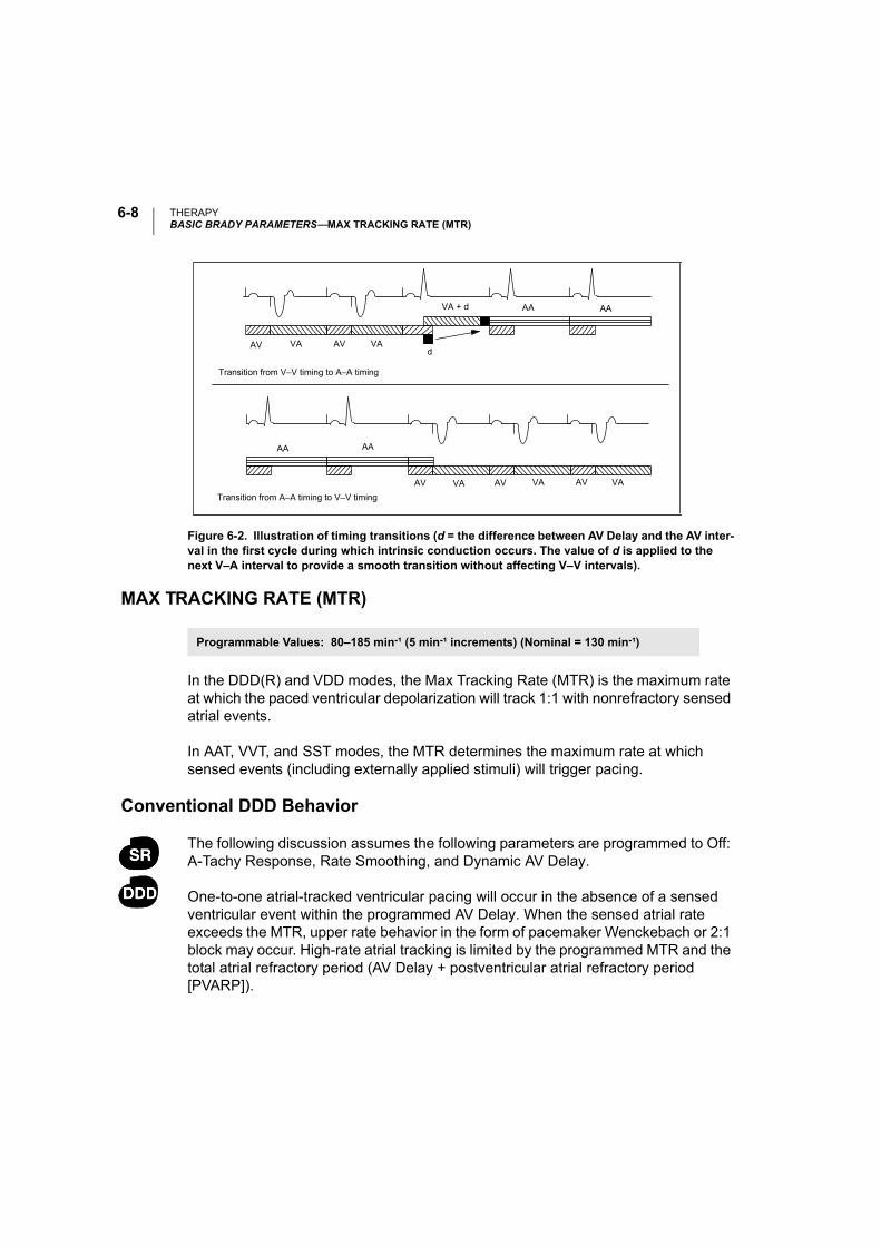
THERAPYBASIC BRADY PARAMETERS—MAX TRACKING RATE (MTR)
6-8
MAX TRACKING RATE (MTR)
In the DDD(R) and VDD modes, the Max Tracking Rate (MTR) is the maximum rate at which the paced ventricular depolarization will track 1:1 with nonrefractory sensed atrial events.
In AAT, VVT, and SST modes, the MTR determines the maximum rate at which sensed events (including externally applied stimuli) will trigger pacing.
Conventional DDD Behavior
The following discussion assumes the following parameters are programmed to Off: A-Tachy Response, Rate Smoothing, and Dynamic AV Delay.
One-to-one atrial-tracked ventricular pacing will occur in the absence of a sensed ventricular event within the programmed AV Delay. When the sensed atrial rate exceeds the MTR, upper rate behavior in the form of pacemaker Wenckebach or 2:1 block may occur. High-rate atrial tracking is limited by the programmed MTR and the total atrial refractory period (AV Delay + postventricular atrial refractory period [PVARP]).
Figure 6-2. Illustration of timing transitions (d = the difference between AV Delay and the AV inter-val in the first cycle during which intrinsic conduction occurs. The value of d is applied to the next V–A interval to provide a smooth transition without affecting V–V intervals).
Transition from A–A timing to V–V timing
VA + d AA AA
AV VA AV VAd
AA AA
AV VA AV VA AV VA
Transition from V–V timing to A–A timing
Programmable Values: 80–185 min-¹ (5 min-¹ increments) (Nominal = 130 min-¹)
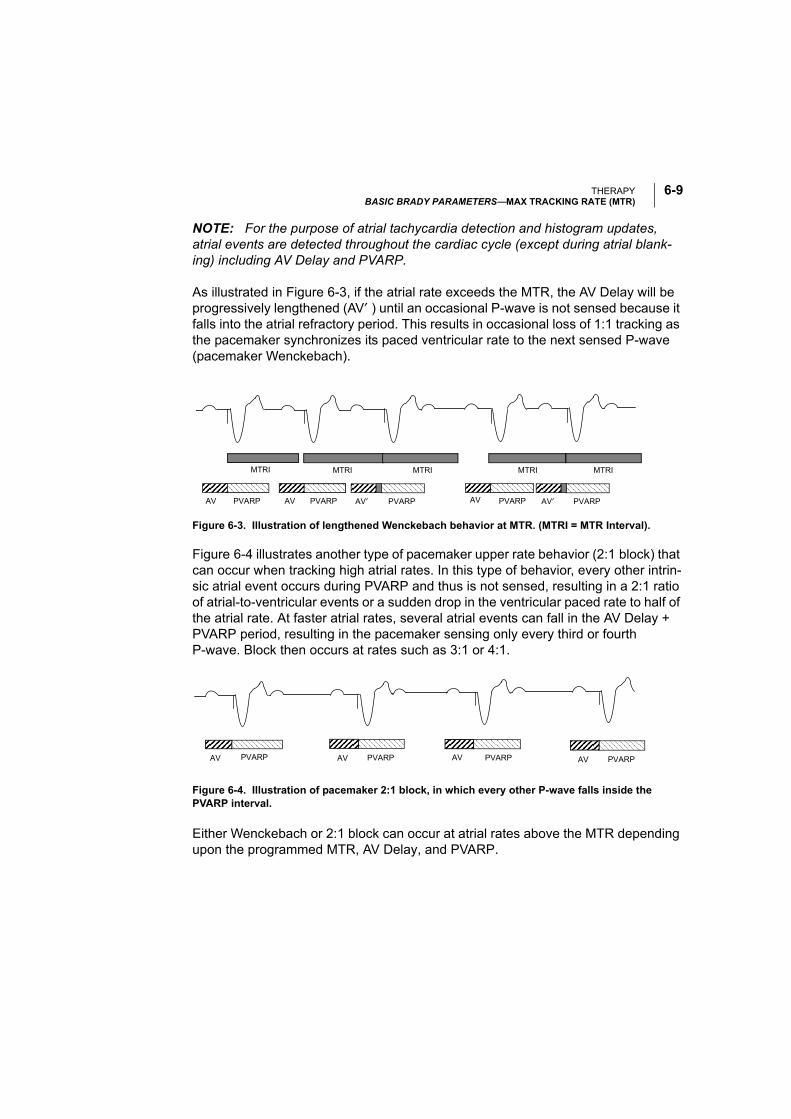
THERAPYBASIC BRADY PARAMETERS—MAX TRACKING RATE (MTR)
6-9
NOTE: For the purpose of atrial tachycardia detection and histogram updates, atrial events are detected throughout the cardiac cycle (except during atrial blank-ing) including AV Delay and PVARP.
As illustrated in Figure 6-3, if the atrial rate exceeds the MTR, the AV Delay will be progressively lengthened (AV′ ) until an occasional P-wave is not sensed because it falls into the atrial refractory period. This results in occasional loss of 1:1 tracking as the pacemaker synchronizes its paced ventricular rate to the next sensed P-wave (pacemaker Wenckebach).
Figure 6-4 illustrates another type of pacemaker upper rate behavior (2:1 block) that can occur when tracking high atrial rates. In this type of behavior, every other intrin-sic atrial event occurs during PVARP and thus is not sensed, resulting in a 2:1 ratio of atrial-to-ventricular events or a sudden drop in the ventricular paced rate to half of the atrial rate. At faster atrial rates, several atrial events can fall in the AV Delay + PVARP period, resulting in the pacemaker sensing only every third or fourth P-wave. Block then occurs at rates such as 3:1 or 4:1.
Figure 6-4. Illustration of pacemaker 2:1 block, in which every other P-wave falls inside the PVARP interval.
Either Wenckebach or 2:1 block can occur at atrial rates above the MTR depending upon the programmed MTR, AV Delay, and PVARP.
Figure 6-3. Illustration of lengthened Wenckebach behavior at MTR. (MTRI = MTR Interval).
AV PVARP AV PVARPAV′ PVARPAV PVARP AV′ PVARP
MTRI MTRI MTRI MTRI MTRI
AV PVARP AV PVARP AV PVARP AV PVARP
THERAPYBASIC BRADY PARAMETERS—MAX SENSOR RATE
6-10
In order to avoid complete closure of the sensing window at MTR resulting in 2:1 block, the programmer does not allow programming to permanent modes with an MTR interval shorter than the sum of the AV Delay and the PVARP. The sensing window should be maximized by programming the appropriate AV Delay and PVARP. At rates close to the MTR, the sensing window can be maximized by pro-gramming Dynamic AV Delay, and Wenckebach behavior will be minimized.
Programming Rate Smoothing and/or A-Tachy Response to On may reduce or elim-inate rapid changes in the paced ventricular rate caused by sensed atrial rates above the MTR.
MAX SENSOR RATE
Max Sensor Rate (MSR) is the maximum pacing rate allowed as a result of sensor control. The MSR parameter is independently programmable at, above, or below the MTR. It is possible to program the MSR greater than, equal to, or less than the ATR Trigger Rate unless the permanent mode is nonrate-adaptive and the ATR Fallback Mode is rate-adaptive, in which case the PRM prevents the user from programming an MSR greater than the ATR Trigger Rate.
• If the MSR setting is higher than the MTR, AV synchronous pacing above the MTR may occur if the sensor rate exceeds the MTR.
• If the MSR setting is lower than the MTR, ventricular pacing above the MSR can occur only in response to intrinsic atrial activity.
CAUTION: Adaptive-rate pacing is not limited by refractory periods. A long refrac-tory period programmed in combination with a high MSR can result in asynchro-nous pacing during refractory periods, since the combination can cause a very small sensing window or none at all.
Examples:
• An AV Delay setting of 200 ms combined with a PVARP of 300 ms will result in asynchronous atrial pacing at sensor-indicated rates above 120 min-¹ in dual-chamber adaptive-rate pacemakers.
• A refractory period of 500 ms will result in asynchronous pacing at sen-sor-indicated rates above 120 min-¹ in atrial adaptive-rate pacemakers.
Programmable Values: 80–185 min-¹ (5-min-¹ increment) (Nominal = 130 min-¹)

THERAPYBASIC BRADY PARAMETERS—AV DELAY (PACED)
6-11
AV DELAY (PACED)
The AV Delay is the programmable period from the beginning of an atrial event, either intrinsic or paced, to the paced ventricular event. AV Delay is applicable to all dual-chamber modes. In the DDI(R), VDD, and DDD(R) modes, the pacemaker delivers a ventricular pace at the end of the AV Delay unless inhibited by an intrinsic ventricular depolarization or if the MTR would be exceeded. In DOO mode, the device delivers a ventricular pace at the end of the AV Delay regardless of intrinsic ventricular depolarization.
AV Delay can be programmed to a fixed value—AV Delay (paced)—or can be calcu-lated dynamically based on the previous A–A interval (Dynamic AV Delay). Dynamic AV Delay is nominally programmed On. Refer to “Dynamic AV Delay” on page 6-44 for additional information.
If a fixed AV Delay is programmed, the AV Delay will remain unchanged as the rate increases. This can result in a significant reduction in the sensing window at MTR.
The Dynamic AV Delay (on the AV Delay submenu) provides a more physiologic AV coupling across the programmed rate range and maximizes the sensing window at higher rates. This minimizes the occurrence of pacemaker Wenckebach behavior when the atrial rate exceeds the MTR. The applied AV Delay will never be less than 10 ms or longer than 300 ms.
NOTE: Long programmed AV intervals (≥ 250 ms) should be used with caution. The physician should evaluate the patient and weigh the potential benefit of promot-ing intrinsic conduction against the potential risk of hemodynamic compromise, such as pacemaker syndrome and diastolic mitral regurgitation.
Refer to “AV Delay Submenu” on 6-44 for information about Dynamic AV Delay and Sensed AV Offset.
PULSE WIDTH
The Pulse Width, also referred to as pulse duration, determines how long the output pulse will be applied between the pacing electrodes. Atrial and ventricular pulse widths are independently programmable.
Programmable Values: 10–300 ms (10-ms increments) (Nominal = 150 ms)
Programmable Values: 0.05 ms and 0.1–1.0 ms (0.1-ms increments) (Nominal = 0.4 ms)
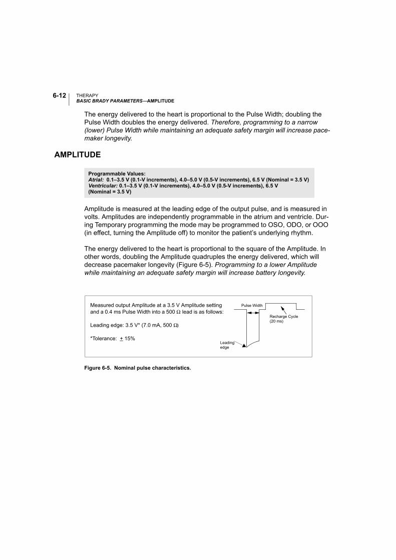
THERAPYBASIC BRADY PARAMETERS—AMPLITUDE
6-12
The energy delivered to the heart is proportional to the Pulse Width; doubling the Pulse Width doubles the energy delivered. Therefore, programming to a narrow (lower) Pulse Width while maintaining an adequate safety margin will increase pace-maker longevity.
AMPLITUDE
Amplitude is measured at the leading edge of the output pulse, and is measured in volts. Amplitudes are independently programmable in the atrium and ventricle. Dur-ing Temporary programming the mode may be programmed to OSO, ODO, or OOO (in effect, turning the Amplitude off) to monitor the patient’s underlying rhythm.
The energy delivered to the heart is proportional to the square of the Amplitude. In other words, doubling the Amplitude quadruples the energy delivered, which will decrease pacemaker longevity (Figure 6-5). Programming to a lower Amplitude while maintaining an adequate safety margin will increase battery longevity.
Figure 6-5. Nominal pulse characteristics.
Programmable Values: Atrial: 0.1–3.5 V (0.1-V increments), 4.0–5.0 V (0.5-V increments), 6.5 V (Nominal = 3.5 V) Ventricular: 0.1–3.5 V (0.1-V increments), 4.0–5.0 V (0.5-V increments), 6.5 V (Nominal = 3.5 V)
Leadingedge
Recharge Cycle(20 ms)
Pulse WidthMeasured output Amplitude at a 3.5 V Amplitude setting and a 0.4 ms Pulse Width into a 500 Ω lead is as follows:
Leading edge: 3.5 V* (7.0 mA, 500 Ω)
*Tolerance: + 15%
THERAPYBASIC BRADY PARAMETERS—SENSITIVITY
6-13
SENSITIVITY
The Sensitivity parameter allows the pacemaker to detect intrinsic cardiac signals that exceed the programmed value.
When Sensitivity is programmed to a very sensitive setting (i.e., a low value), the pacemaker may detect signals unrelated to cardiac depolarization (oversensing, such as sensing of myopotentials). When Sensitivity is programmed to a less sensi-tive setting (i.e., a higher value), the pacemaker may not detect the cardiac depolar-ization signal (undersensing). For manual programming, Sensitivity must be programmed to a value that prevents sensing of extraneous signals, but ensures accurate sensing of intrinsic cardiac signals. Intrinsic atrial signals are typically smaller than ventricular signals, so lower Sensitivity settings are typically pro-grammed for the atrium. When a single-pass VDD lead is used with a dual-chamber device, the atrial electrodes might not be in contact with the atrial wall. In this case, the measured depolarization signal has a relatively low Amplitude and could require a Sensitivity setting as low as 0.15 mV. Careful consideration should be given to programming the sensing threshold below 0.3 mV (bipolar) and 2.0 mV (unipolar) due to the possibility of inappropriate far field sensing, myopotential sensing, and sensing of electromagnetic interference.
REFRACTORY PERIODS
The refractory period is the interval following a paced or sensed event during which the pacemaker is not inhibited or triggered by detected electrical activity. Refractory periods avoid triggering or inhibition of pacemaker events due to detection of inap-propriate signals such as retrograde P-waves, far-field R-waves, or noise.
Refer to Chapter 6 “Refractory Submenu” on page 6-48 for information about PVARP after PVC/PAC and V-Blanking after A-Pace or A-Blanking after V-Pace.
Programmable Values: Atrial: 0.15, 0.25, 0.50, 0.75, and 1.0–8.0 mV (0.5-mV increments), 9.0, 10.0 mV(Nominal = 0.75 mV)Ventricular/Single: 0.25, 0.50, 0.75, 1.0–8.0 mV (0.5-mV increments), 9.0, 10.0 mV (Nominal = 2.5 mV)
THERAPYBASIC BRADY PARAMETERS—REFRACTORY PERIODS
6-14
Atrial Refractory Period
In three single-chamber atrial modes (AAT, AAI, AAIR), the Atrial Refractory period is defined as the period after an atrial event, either paced or sensed, when activity in the atrium does not inhibit or trigger an atrial stimulus.
Adaptive-rate pacing is not inhibited during refractory periods. See “Max Sensor Rate” on page 6-10 for further discussion.
Post-Ventricular Atrial Refractory Period (PVARP)
The post-ventricular atrial refractory (PVARP) is defined as the period after a ven-tricular event, either paced or sensed, when activity in the atrium does not inhibit an atrial stimulus nor trigger a ventricular stimulus. It is designed to prevent the atrial channel from sensing the ventricular pacing pulse, the far-field R-waves, or retro-grade P-waves.
PVARP should be programmed to a value greater than the patient’s V–A retrograde conduction time to prevent the atrial channel from sensing a retrograde atrial depo-larization and possibly initiating pacemaker-mediated tachycardia.
Using a long PVARP shortens the atrial sensing window. Programming a long PVARP in combination with a long AV Delay can cause 2:1 block to occur abruptly at the programmed MTR. See “Max Tracking Rate” on page 6-8 for further discus-sion.
Ventricular Refractory Period
The ventricular refractory period is defined as the period following a ventricular event, either paced or sensed, when sensed electrical activity in the ventricle does not inhibit the pacemaker. This parameter is available in any mode in which ventric-ular sensing is enabled.
Programmable Values: 150–500 ms (10-ms increments) (Nominal = 300 ms)
Programmable Values: 150–500 ms (10-ms increments) (Nominal = 250 ms)
Programmable Values: 200–500 ms (10-ms increments) (Nominal = 250 ms)

THERAPYBASIC BRADY PARAMETERS—PACE/SENSE
6-15
Use of a long Ventricular Refractory period shortens the ventricular sensing window. Programming the Ventricular Refractory period to a value greater than PVARP can lead to competitive pacing. For example, if the Ventricular Refractory is longer than PVARP, an atrial event can be appropriately sensed following PVARP and intrinsic conduction to the ventricle falls into the Ventricular Refractory period. In this case, the pacemaker will not sense the ventricular depolarization and will pace at the end of the AV Delay, resulting in competitive pacing.
Adaptive-rate pacing is not inhibited during Refractory periods.
PACE/SENSE
The Pace/Sense field indicates the programmed lead polarity. The polarity cannot be changed from this screen; to change polarity, select the Lead Configuration sub-menu button.
THERAPYSENSOR SUBMENU—ADAPTIVE-RATE PACING
6-16
SENSOR SUBMENU—
ADAPTIVE-RATE PACING
In the adaptive-rate modes (i.e., any mode ending with R), an accelerometer sensor is used to detect changes in metabolic demand and to increase the pacing rate accordingly. Adaptive-rate pacing is available in the DDDR, DDIR, DOOR, VVIR, AAIR, SSIR, VOOR, AOOR, and SOOR permanent modes as well as the DDIR and VDIR fallback modes. In these modes, the pacemaker will pace at the sensor-indi-cated rate unless inhibited by sensed events. The clinical benefit of adaptive-rate pacing using a sensor has been shown in a previous clinical studies.
ACCELEROMETER
The Accelerometer detects motion associated with physical activity and generates an electronic signal that is proportional to the magnitude of motion resulting from body movement.
Based on the accelerometer input, the pacemaker estimates the patient’s energy expenditure as a result of exercise and then translates it into a rate increase. To measure acceleration, both the frequency and the amplitude of the sensor signal
Accelerometer Response Factor
PARAMETERSBrady Parameters
Sensors
Programmable Values: Off, On, ATR-onlya (Nominal = Off)
a. ATR only is not a user selectable setting. It is set when the primary mode is not rate-responsive and a rate-responsive ATR Fallback Mode is selected.
Brady Parameters Sensors
THERAPYSENSOR SUBMENU—ACCELEROMETER
6-17
are evaluated during signal processing. Signal frequency reflects how often an activity occurs, such as the number of steps per minute taken during a brisk walk. Signal amplitude reflects the force of the motion—for example, the more deliberate steps taken while walking. See Chapter 3 “Technical Information” for further discus-sion of accelerometer function.
If the pacemaker is permanently programmed to a nonadaptive-rate mode, it is pos-sible to program ATR Fallback Mode to an adaptive-rate mode using the Accelerom-eter sensor. In this case, on the sensor submenu, the Accelerometer field will display ATR Only.
The following programmable parameters control the pacemaker’s response to the sensor values generated by the Accelerometer:
• Response Factor
• Activity Threshold
• Reaction Time
• Recovery Time
Response Factor (Accelerometer)
The Accelerometer Response Factor parameter determines the pacing rate that will occur above the LRL at various levels of patient activity. Figure 6-6 shows the rela-tionship of the Response Factor settings.
Programmable Values: Passive, 1–16 (Nominal = 8)
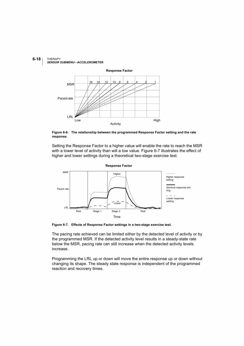
THERAPYSENSOR SUBMENU—ACCELEROMETER
6-18
Figure 6-6. The relationship between the programmed Response Factor setting and the rate response.
Setting the Response Factor to a higher value will enable the rate to reach the MSR with a lower level of activity than will a low value. Figure 6-7 illustrates the effect of higher and lower settings during a theoretical two-stage exercise test.
Figure 6-7. Effects of Response Factor settings in a two-stage exercise test.
The pacing rate achieved can be limited either by the detected level of activity or by the programmed MSR. If the detected activity level results in a steady-state rate below the MSR, pacing rate can still increase when the detected activity levels increase.
Programming the LRL up or down will move the entire response up or down without changing its shape. The steady state response is independent of the programmed reaction and recovery times.
16 14 12 10 8 6 4 2 1
ActivityLow High
MSR
LRL
Response Factor
Paced rate
Stage 2
Time
Higher
Lower
LRL
Response Factor
Rest Stage 1 Rest
Higher responsesetting
MSR
Lower responsesetting
Paced rateNominal response set-ting
THERAPYSENSOR SUBMENU—ACCELEROMETER
6-19
The nominal setting has been shown to be appropriate for the majority of the patients in a previous study, and therefore is recommended for use in monitoring the rate response prior to programming changes.
The Passive setting can be used to allow accelerometer trending without a rate response.
Advanced Accelerometer Parameters
Activity Threshold
The Activity Threshold prevents the pacemaker from increasing the rate due to low-intensity extraneous motion (e.g., motion caused by respiration, heart beat, or, in some cases, tremor associated with Parkinson’s disease). The pacemaker will not increase the paced rate above the LRL until the accelerometer signal has increased above the Activity Threshold. Select an Activity Threshold setting that allows a rate increase with minor activity (such as walking), but high enough so that the pacing rate will not increase inappropriately when the patient is inactive. A lower Activity Threshold setting will be easily exceeded by a minimum of motion, while a higher setting will require a greater amount of motion to result in an increased pac-ing rate (Figure 6-8). The nominal setting has been shown to be appropriate for the majority of the patients in a previous study, and therefore is recommended for use in monitoring the rate response prior to programming changes.
Programmable Values: V-Low, Low, Med-Lo, Medium, Med-Hi, High, V-High (Nominal = Medium)
Sensors AccelerometerBrady Parameters
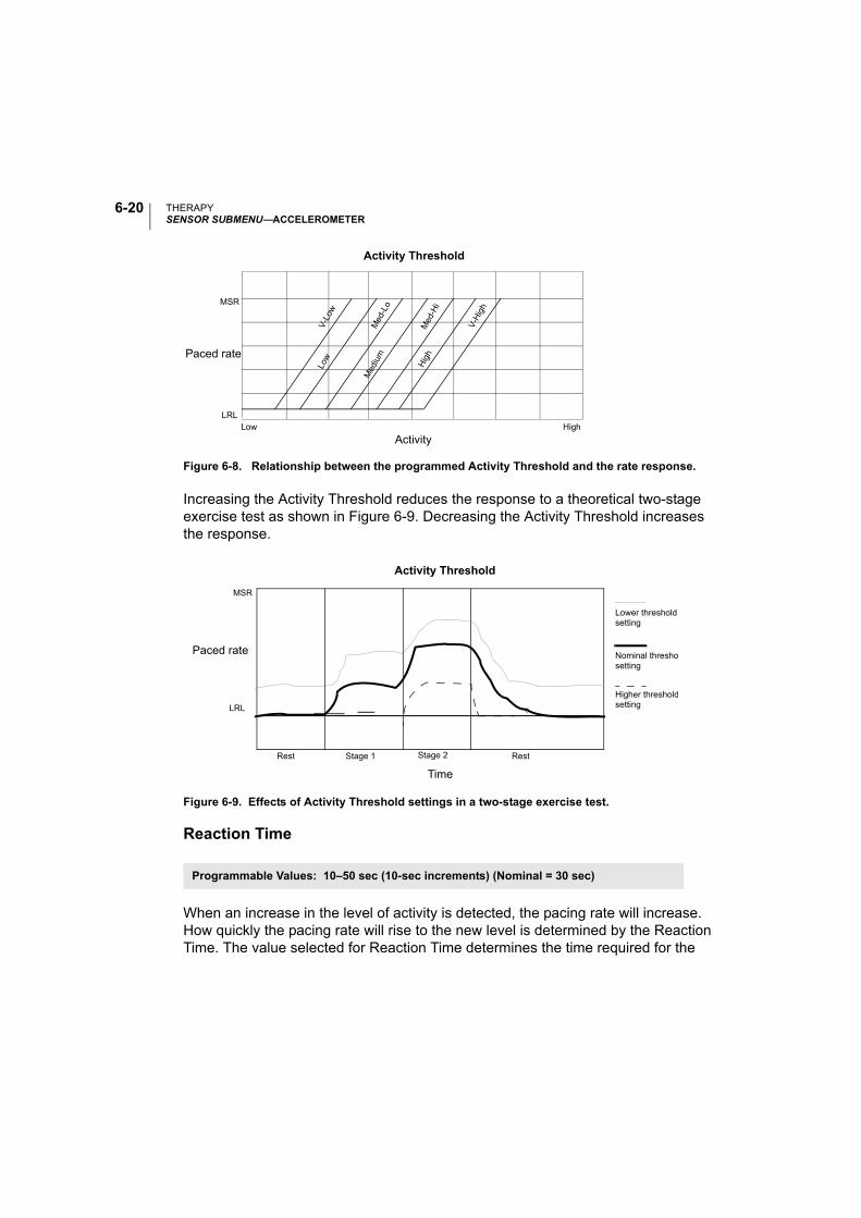
THERAPYSENSOR SUBMENU—ACCELEROMETER
6-20
Figure 6-8. Relationship between the programmed Activity Threshold and the rate response.
Increasing the Activity Threshold reduces the response to a theoretical two-stage exercise test as shown in Figure 6-9. Decreasing the Activity Threshold increases the response.
Reaction Time
When an increase in the level of activity is detected, the pacing rate will increase. How quickly the pacing rate will rise to the new level is determined by the Reaction Time. The value selected for Reaction Time determines the time required for the
Figure 6-9. Effects of Activity Threshold settings in a two-stage exercise test.
Programmable Values: 10–50 sec (10-sec increments) (Nominal = 30 sec)
ActivityLow High
MSR
LRL
Activity Threshold
V-L
owLo
w
Med
-Lo
Med
ium
Med
-Hi
Hig
h
V-H
igh
Paced rate
Time
Paced rate
Lower thresholdsetting
LRL
Activity Threshold
Rest Stage 1 Rest
MSR
Nominal threshosetting
Higher thresholdsetting
Stage 2
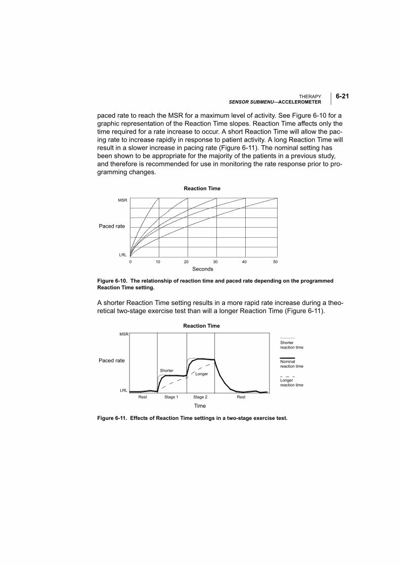
THERAPYSENSOR SUBMENU—ACCELEROMETER
6-21
paced rate to reach the MSR for a maximum level of activity. See Figure 6-10 for a graphic representation of the Reaction Time slopes. Reaction Time affects only the time required for a rate increase to occur. A short Reaction Time will allow the pac-ing rate to increase rapidly in response to patient activity. A long Reaction Time will result in a slower increase in pacing rate (Figure 6-11). The nominal setting has been shown to be appropriate for the majority of the patients in a previous study, and therefore is recommended for use in monitoring the rate response prior to pro-gramming changes.
Figure 6-10. The relationship of reaction time and paced rate depending on the programmed Reaction Time setting.
A shorter Reaction Time setting results in a more rapid rate increase during a theo-retical two-stage exercise test than will a longer Reaction Time (Figure 6-11).
Figure 6-11. Effects of Reaction Time settings in a two-stage exercise test.
MSR
LRL
0
Seconds
10 20 30 40 50
Reaction Time
Paced rate
Stage 2
Time
ShorterLonger
LRL
Rest Stage 1 Rest
Shorterreaction time
MSR
Nominalreaction time
Longerreaction time
Paced rate
Reaction Time
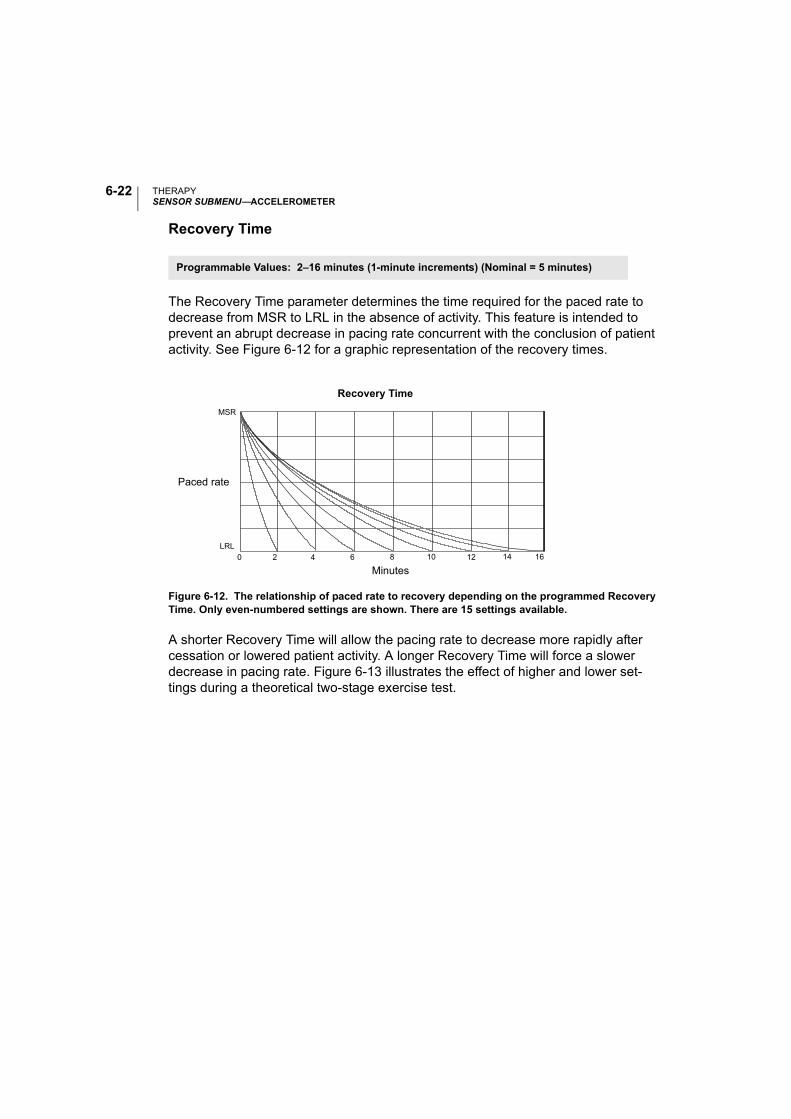
THERAPYSENSOR SUBMENU—ACCELEROMETER
6-22
Recovery Time
The Recovery Time parameter determines the time required for the paced rate to decrease from MSR to LRL in the absence of activity. This feature is intended to prevent an abrupt decrease in pacing rate concurrent with the conclusion of patient activity. See Figure 6-12 for a graphic representation of the recovery times.
Figure 6-12. The relationship of paced rate to recovery depending on the programmed Recovery Time. Only even-numbered settings are shown. There are 15 settings available.
A shorter Recovery Time will allow the pacing rate to decrease more rapidly after cessation or lowered patient activity. A longer Recovery Time will force a slower decrease in pacing rate. Figure 6-13 illustrates the effect of higher and lower set-tings during a theoretical two-stage exercise test.
Programmable Values: 2–16 minutes (1-minute increments) (Nominal = 5 minutes)
LRL0 2 4 10 12 166 8 14
Paced rate
MSR
Recovery Time
Minutes
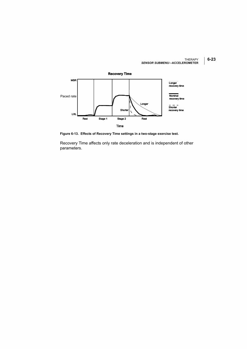
THERAPYSENSOR SUBMENU—ACCELEROMETER
6-23
Figure 6-13. Effects of Recovery Time settings in a two-stage exercise test.
Recovery Time affects only rate deceleration and is independent of other parameters.
Shorter
Longer
LRL
Time
Rest Stage 1 Stage 2 Rest
Recovery Time
Shorterrecovery time
Nominalrecovery time
Longerrecovery time
MSR
Paced rate
Shorter
Longer
LRL
Time
Rest Stage 1 Stage 2 Rest
Recovery Time
Shorterrecovery time
Nominalrecovery time
Longerrecovery time
MSR
Shorter
Longer
LRL
Time
Rest Stage 1 Stage 2 Rest
Recovery Time
Shorterrecovery time
Nominalrecovery time
Longerrecovery time
MSR
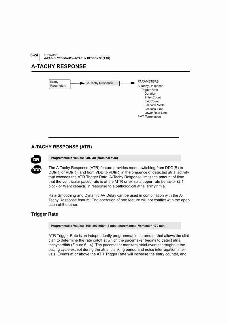
THERAPYA-TACHY RESPONSE—A-TACHY RESPONSE (ATR)
6-24
A-TACHY RESPONSE—
A-TACHY RESPONSE (ATR)
The A-Tachy Response (ATR) feature provides mode switching from DDD(R) to DDI(R) or VDI(R), and from VDD to VDI(R) in the presence of detected atrial activity that exceeds the ATR Trigger Rate. A-Tachy Response limits the amount of time that the ventricular paced rate is at the MTR or exhibits upper-rate behavior (2:1 block or Wenckebach) in response to a pathological atrial arrhythmia.
Rate Smoothing and Dynamic AV Delay can be used in combination with the A-Tachy Response feature. The operation of one feature will not conflict with the oper-ation of the other.
Trigger Rate
ATR Trigger Rate is an independently programmable parameter that allows the clini-cian to determine the rate cutoff at which the pacemaker begins to detect atrial tachycardias (Figure 6-14). The pacemaker monitors atrial events throughout the pacing cycle except during the atrial blanking period and noise interrogation inter-vals. Events at or above the ATR Trigger Rate will increase the entry counter, and
PARAMETERS
A-Tachy Response Trigger Rate Duration
Entry CountExit Count
Fallback Mode Fallback Time Lower Rate LimitPMT Termination
Brady Parameters
A-Tachy Response
Programmable Values: Off, On (Nominal =On)
Programmable Values: 100–200 min-¹ (5-min-¹ increments) (Nominal = 170 min-¹)
THERAPYA-TACHY RESPONSE—A-TACHY RESPONSE (ATR)
6-25
events below the ATR will decrease the entry counter. When the ATR detection counter reaches the programmable Entry Count, the ATR Duration begins and the Exit Count starts (Figure 6-14 on page 6-28). When the ATR Exit Count reaches zero at any point in time, ATR Duration and/or ATR Fallback will be terminated and the ATR algorithm will be reset. An event marker will be generated whenever the ATR Exit Count or entry counter is incremented or decremented.
Entry Count
The Entry Count is an independently programmable parameter that allows the clini-cian to determine how quickly an atrial arrhythmia is initially detected. The lower the programmable value, the fewer fast atrial events are required to fulfill initial detec-tion. Once the number of fast atrial events detected equals the programmable Entry Count, ATR Duration begins and the Exit Count is started.
CAUTION: Exercise care when programming the Entry Count to low values in con-junction with a short Duration. This combination allows mode switching with very few fast atrial beats. If the Entry Count were programmed to 2 and the Duration to 0, for example, ATR mode switching could occur on two fast atrial intervals. In these instances, a short series of premature atrial events could cause the device to mode switch.
Exit Count
The Exit Count is an independently programmable parameter that allows the clini-cian to determine how quickly the A-Tachy Response algorithm is terminated once the atrial arrhythmia no longer is detected. The lower the programmable value, the more quickly the pacemaker will return to dual-chamber pacing. Once the number of slow atrial events detected equals the programmable Exit Count, ATR Duration and/or ATR Fallback Mode will be terminated and the A-Tachy Response algorithm will be reset. The exit counter is loaded with the programmable value and begins its count once the Entry Count criteria are fulfilled.
CAUTION: Exercise care when programming the Exit Count to low values. If the Exit Count were programmed to 2, for example, a few cycles of atrial under-sensing could cause termination of mode switching.
Programmable Values: 1–8 cycles (increments of 1) (Nominal = 8 cycles)
Programmable Values: 1–8 cycles (increments of 1) (Nominal = 8 cycles)

THERAPYA-TACHY RESPONSE—A-TACHY RESPONSE (ATR)
6-26
Duration
ATR Duration is a programmable parameter that determines the number of ventricu-lar cycles during which the atrial events continue to be evaluated after initial detec-tion. If the atrial tachycardia persists for the programmed duration, mode switching occurs and the ventricular rate begins to decrease to the sensor rate or the ATR Lower Rate Limit (Figure 6-14 on page 6-28). The Duration feature is intended to avoid mode switching due to nonsustained episodes of atrial tachycardia. Whenever the ATR Exit Count reaches 0 during Duration, the A-Tachy Response algorithm will be reset.
Fallback Mode
Once Duration has been fulfilled, the pacemaker will automatically switch to the pro-grammed Fallback Mode. After switching modes, the device gradually decreases the ventricular paced rate to the sensor-indicated rate or the ATR Lower Rate Limit, depending on the programmed Fallback Mode. The decrease in ventricular paced rate is controlled by the Fallback Time parameter.
Fallback Time
The Fallback Time determines how quickly the rate in fallback will decrease to the ATR Lower Rate Limit or sensor rate. The Fallback Time parameter controls the decrease in the paced rate.
During fallback, the following features will be disabled:
• Rate Smoothing, until fallback reaches ATR Lower Rate Limit or the sensor-indi-cated rate
• Rate Hysteresis and Search Hysteresis
All sensor parameters must be programmed when the adaptive-rate Fallback Mode is selected. When the pacemaker is permanently programmed to an adaptive-rate
Programmable Values: 0, 8–2048 cycles (powers of 2) (Nominal = 8 cycles)
Programmable Values: VDI(R), DDI(R) (Nominal = VDI)
Programmable Values: 0–120 sec (5-sec increments) (Nominal = 30 sec)

THERAPYA-TACHY RESPONSE—A-TACHY RESPONSE (ATR)
6-27
mode with an adaptive-rate ATR Fallback Mode, the pacemaker will use the sensor and sensor parameters already in effect at the time of the switch.
If the pacemaker is permanently programmed to a nonadaptive-rate mode, it is pos-sible to program ATR Fallback Mode to an adaptive-rate ATR Fallback Mode using the accelerometer sensor. In this case, on the Sensors submenu, the Accelerometer field will display “ATR Only.”
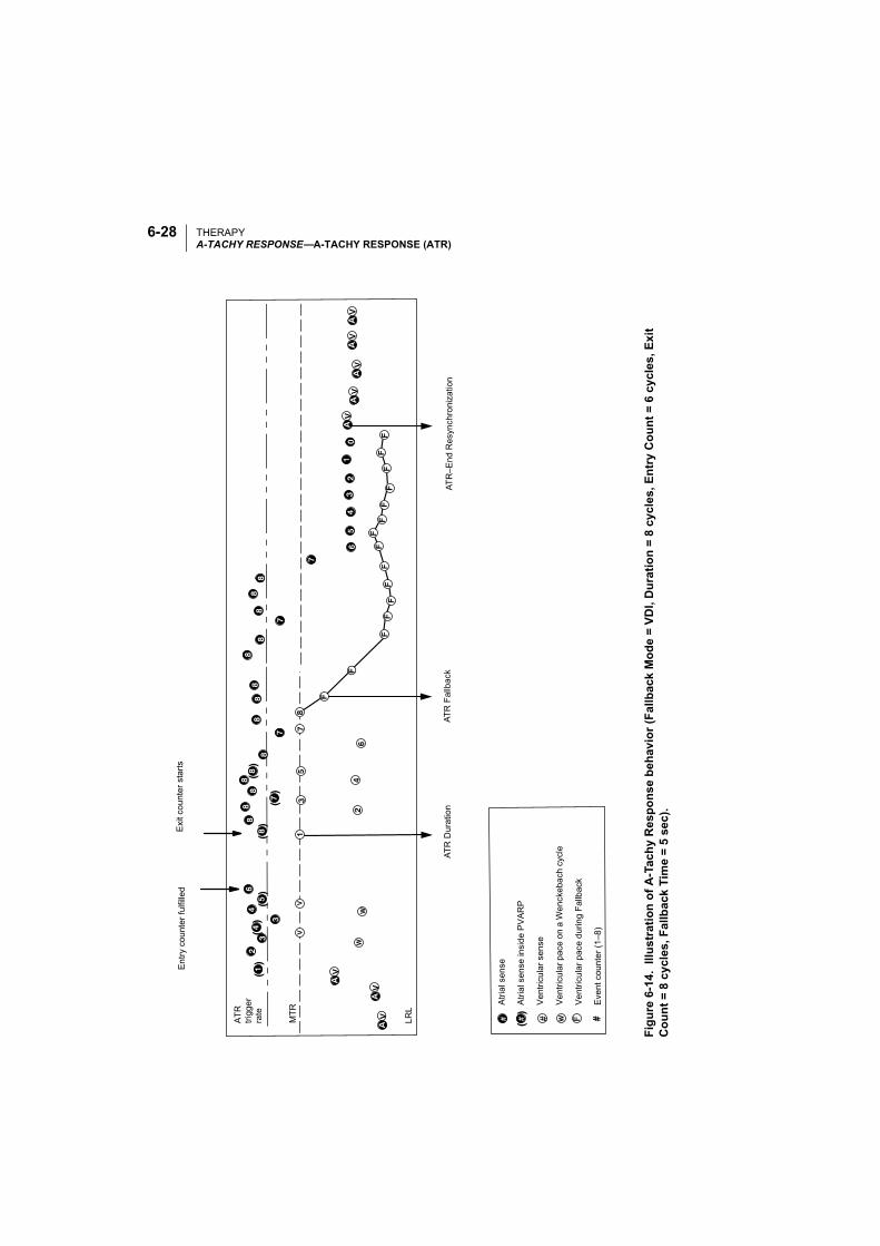
THERAPYA-TACHY RESPONSE—A-TACHY RESPONSE (ATR)
6-28
( )
( )
( )
( )
( )
( )
( ) #
Exi
t co
unt
er s
tart
sE
ntr
y co
unt
er
fulfi
lled
AT
R–E
nd R
esyn
chro
niza
tion
AT
R F
allb
ack
AT
R D
ura
tion
Atr
ial s
ense
Atr
ial s
ens
e in
sid
e P
VA
RP
Ve
ntri
cula
r se
nse
Ve
ntri
cula
r pa
ce o
n a
Wen
ckeb
ach
cyc
le
Ve
ntri
cula
r p
ace
du
ring
Fa
llbac
k
Eve
nt c
oun
ter
(1–8
)
MT
R
LR
L
AT
R
trig
ge
r ra
te
Figu
re6-
14.
Illus
trat
ion
of A
-Tac
hy R
espo
nse
beha
vior
(Fal
lbac
k M
ode
= VD
I, D
urat
ion
= 8
cycl
es, E
ntry
Cou
nt =
6 c
ycle
s, E
xit
Cou
nt =
8 c
ycle
s, F
allb
ack
Tim
e =
5 se
c).
THERAPYA-TACHY RESPONSE—A-TACHY RESPONSE (ATR)
6-29
ATR Lower Rate Limit
The ATR Lower Rate Limit allows an independently programmed LRL during an ATR mode switch. When the ATR Fallback Mode is programmed to a rate-adaptive mode, the response slope is not affected. Consequently, the activity level necessary for rate-adaptive pacing to achieve a specific pacing rate remains the same during ATR Fallback as it does during normal dual-chamber rate-adaptive pacing.
The ATR Lower Rate Limit must be equal to or greater than the permanently pro-grammed brady LRL.
End of ATR Episode
The pacemaker will continue to pace in the Fallback Mode at the sensor-indicated rate or the ATR Lower Rate Limit until the atrial arrhythmia terminates. Upon termi-nation of the arrhythmia, the ATR Exit Count decrements from its programmed value until it reaches 0 (Figure 6-14). The ATR Exit Count is decremented by atrial events slower than the Trigger Rate or paced ventricular events without an intervening atrial event. When the ATR Exit Count reaches 0, the pacing mode automatically resynchronizes to the programmed tracking mode, and P-synchronous pacing is restored.
ATR Diagnostic Data
A-Tachy Response continuously monitors atrial rates. The onset rate is the rate of the last interval when Duration is met. The maximum rate is the rate of the shortest interval after Duration is met. The number of ATR Fallback events is stored for dis-play in the counter function of the device. Event markers are issued whenever the ATR Count increments or decrements, or whenever the other events outlined in Table 6-2 occur.
Programmable Values: 30–50 min-¹ (5-min-¹ increments), 50–90 min-¹ (1-min-¹ incre-ments), 90–150 min-¹ (5-min-¹ increments) (Nominal = 70 min-¹)
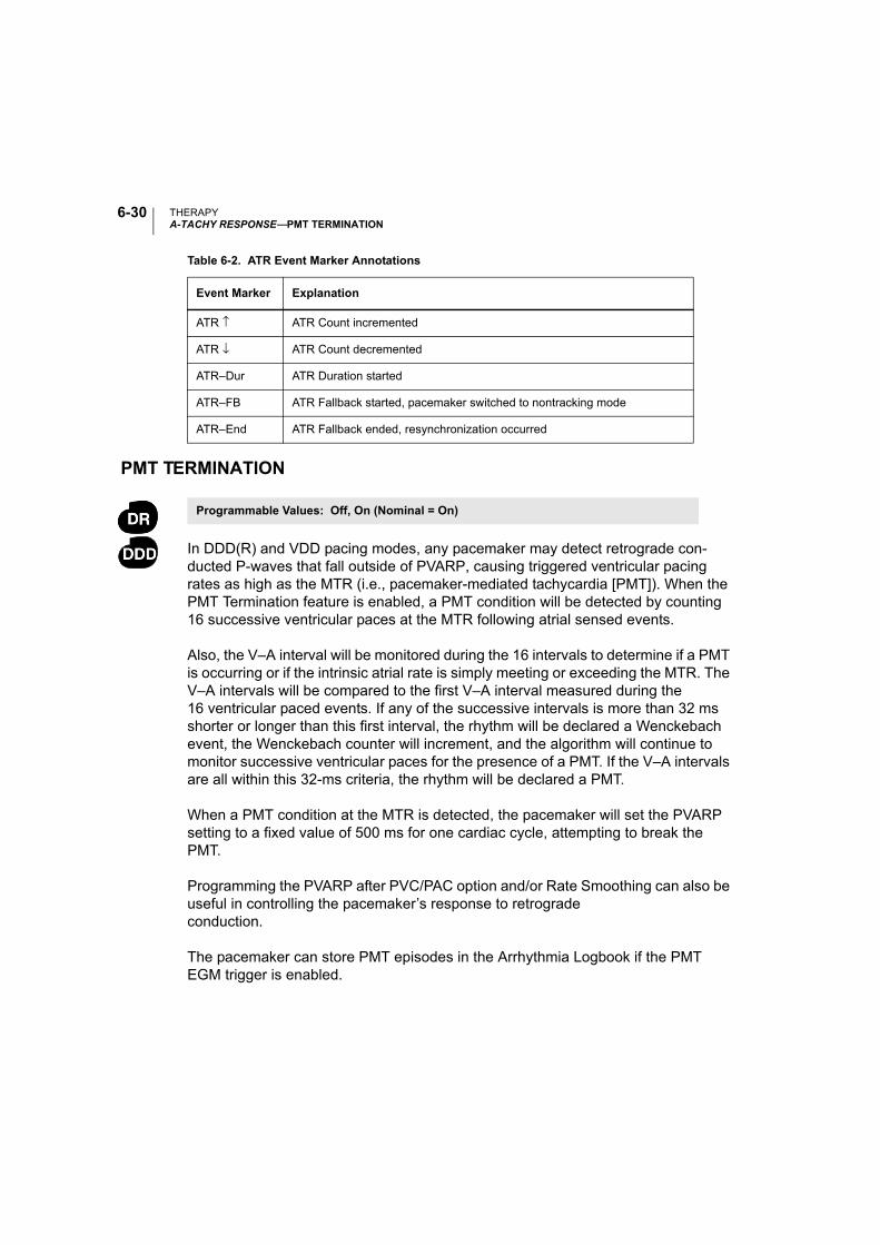
THERAPYA-TACHY RESPONSE—PMT TERMINATION
6-30
PMT TERMINATION
In DDD(R) and VDD pacing modes, any pacemaker may detect retrograde con-ducted P-waves that fall outside of PVARP, causing triggered ventricular pacing rates as high as the MTR (i.e., pacemaker-mediated tachycardia [PMT]). When the PMT Termination feature is enabled, a PMT condition will be detected by counting 16 successive ventricular paces at the MTR following atrial sensed events.
Also, the V–A interval will be monitored during the 16 intervals to determine if a PMT is occurring or if the intrinsic atrial rate is simply meeting or exceeding the MTR. The V–A intervals will be compared to the first V–A interval measured during the 16 ventricular paced events. If any of the successive intervals is more than 32 ms shorter or longer than this first interval, the rhythm will be declared a Wenckebach event, the Wenckebach counter will increment, and the algorithm will continue to monitor successive ventricular paces for the presence of a PMT. If the V–A intervals are all within this 32-ms criteria, the rhythm will be declared a PMT.
When a PMT condition at the MTR is detected, the pacemaker will set the PVARP setting to a fixed value of 500 ms for one cardiac cycle, attempting to break the PMT.
Programming the PVARP after PVC/PAC option and/or Rate Smoothing can also be useful in controlling the pacemaker’s response to retrograde conduction.
The pacemaker can store PMT episodes in the Arrhythmia Logbook if the PMT EGM trigger is enabled.
Table 6-2. ATR Event Marker Annotations
Event Marker Explanation
ATR ↑ ATR Count incremented
ATR ↓ ATR Count decremented
ATR–Dur ATR Duration started
ATR–FB ATR Fallback started, pacemaker switched to nontracking mode
ATR–End ATR Fallback ended, resynchronization occurred
Programmable Values: Off, On (Nominal = On)
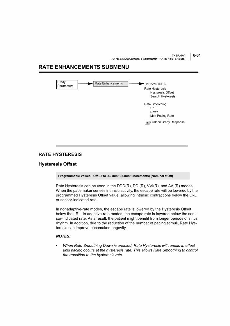
THERAPYRATE ENHANCEMENTS SUBMENU—RATE HYSTERESIS
6-31
RATE ENHANCEMENTS SUBMENU—
RATE HYSTERESIS
Hysteresis Offset
Rate Hysteresis can be used in the DDD(R), DDI(R), VVI(R), and AAI(R) modes. When the pacemaker senses intrinsic activity, the escape rate will be lowered by the programmed Hysteresis Offset value, allowing intrinsic contractions below the LRL or sensor-indicated rate.
In nonadaptive-rate modes, the escape rate is lowered by the Hysteresis Offset below the LRL. In adaptive-rate modes, the escape rate is lowered below the sen-sor-indicated rate. As a result, the patient might benefit from longer periods of sinus rhythm. In addition, due to the reduction of the number of pacing stimuli, Rate Hys-teresis can improve pacemaker longevity.
NOTES:
• When Rate Smoothing Down is enabled, Rate Hysteresis will remain in effect until pacing occurs at the hysteresis rate. This allows Rate Smoothing to control the transition to the hysteresis rate.
PARAMETERS
Rate Hysteresis Hysteresis Offset Search Hysteresis
Rate Smoothing Up Down Max Pacing Rate
Brady Parameters
Rate Enhancements
Sudden Brady Response
Programmable Values: Off, -5 to -80 min-¹ (5-min-¹ increments) (Nominal = Off)
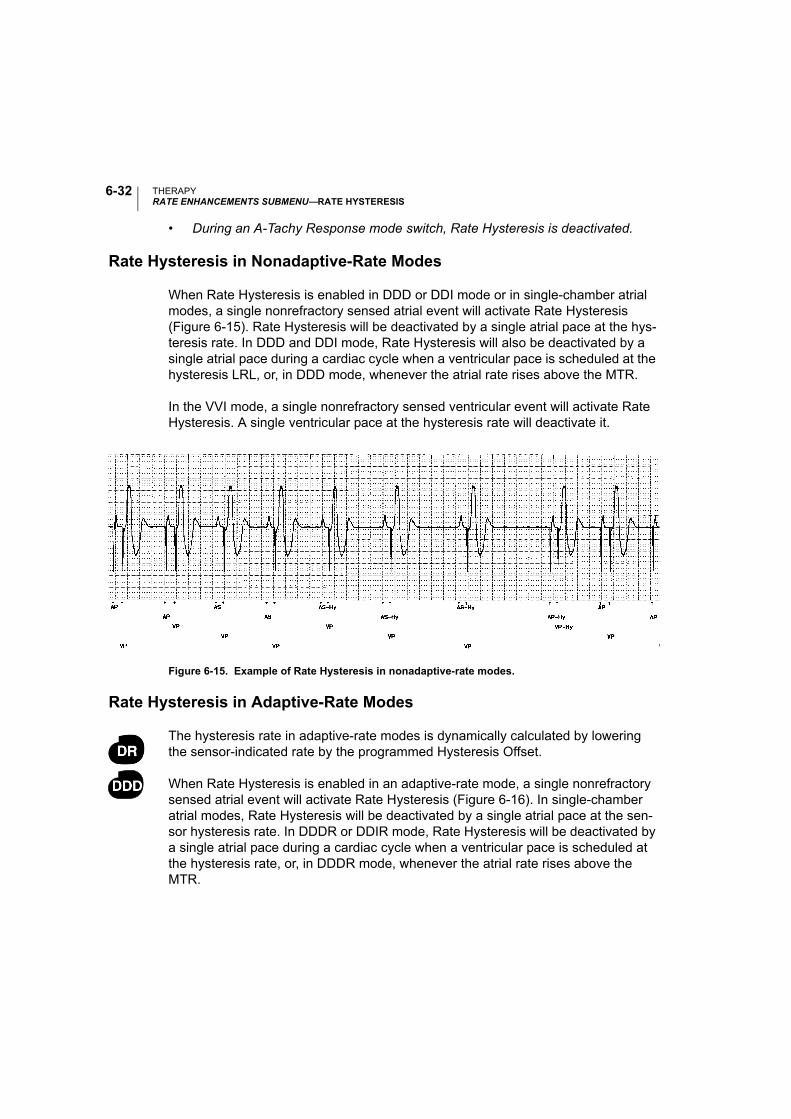
THERAPYRATE ENHANCEMENTS SUBMENU—RATE HYSTERESIS
6-32
• During an A-Tachy Response mode switch, Rate Hysteresis is deactivated.
Rate Hysteresis in Nonadaptive-Rate Modes
When Rate Hysteresis is enabled in DDD or DDI mode or in single-chamber atrial modes, a single nonrefractory sensed atrial event will activate Rate Hysteresis (Figure 6-15). Rate Hysteresis will be deactivated by a single atrial pace at the hys-teresis rate. In DDD and DDI mode, Rate Hysteresis will also be deactivated by a single atrial pace during a cardiac cycle when a ventricular pace is scheduled at the hysteresis LRL, or, in DDD mode, whenever the atrial rate rises above the MTR.
In the VVI mode, a single nonrefractory sensed ventricular event will activate Rate Hysteresis. A single ventricular pace at the hysteresis rate will deactivate it.
Figure 6-15. Example of Rate Hysteresis in nonadaptive-rate modes.
Rate Hysteresis in Adaptive-Rate Modes
The hysteresis rate in adaptive-rate modes is dynamically calculated by lowering the sensor-indicated rate by the programmed Hysteresis Offset.
When Rate Hysteresis is enabled in an adaptive-rate mode, a single nonrefractory sensed atrial event will activate Rate Hysteresis (Figure 6-16). In single-chamber atrial modes, Rate Hysteresis will be deactivated by a single atrial pace at the sen-sor hysteresis rate. In DDDR or DDIR mode, Rate Hysteresis will be deactivated by a single atrial pace during a cardiac cycle when a ventricular pace is scheduled at the hysteresis rate, or, in DDDR mode, whenever the atrial rate rises above the MTR.
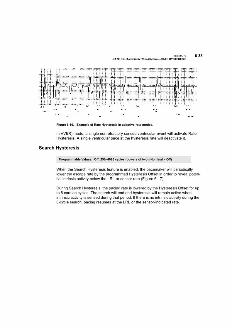
THERAPYRATE ENHANCEMENTS SUBMENU—RATE HYSTERESIS
6-33
Figure 6-16. Example of Rate Hysteresis in adaptive-rate modes.
In VVI(R) mode, a single nonrefractory sensed ventricular event will activate Rate Hysteresis. A single ventricular pace at the hysteresis rate will deactivate it.
Search Hysteresis
When the Search Hysteresis feature is enabled, the pacemaker will periodically lower the escape rate by the programmed Hysteresis Offset in order to reveal poten-tial intrinsic activity below the LRL or sensor rate (Figure 6-17).
During Search Hysteresis, the pacing rate is lowered by the Hysteresis Offset for up to 8 cardiac cycles. The search will end and hysteresis will remain active when intrinsic activity is sensed during that period. If there is no intrinsic activity during the 8-cycle search, pacing resumes at the LRL or the sensor-indicated rate.
Programmable Values: Off, 256–4096 cycles (powers of two) (Nominal = Off)
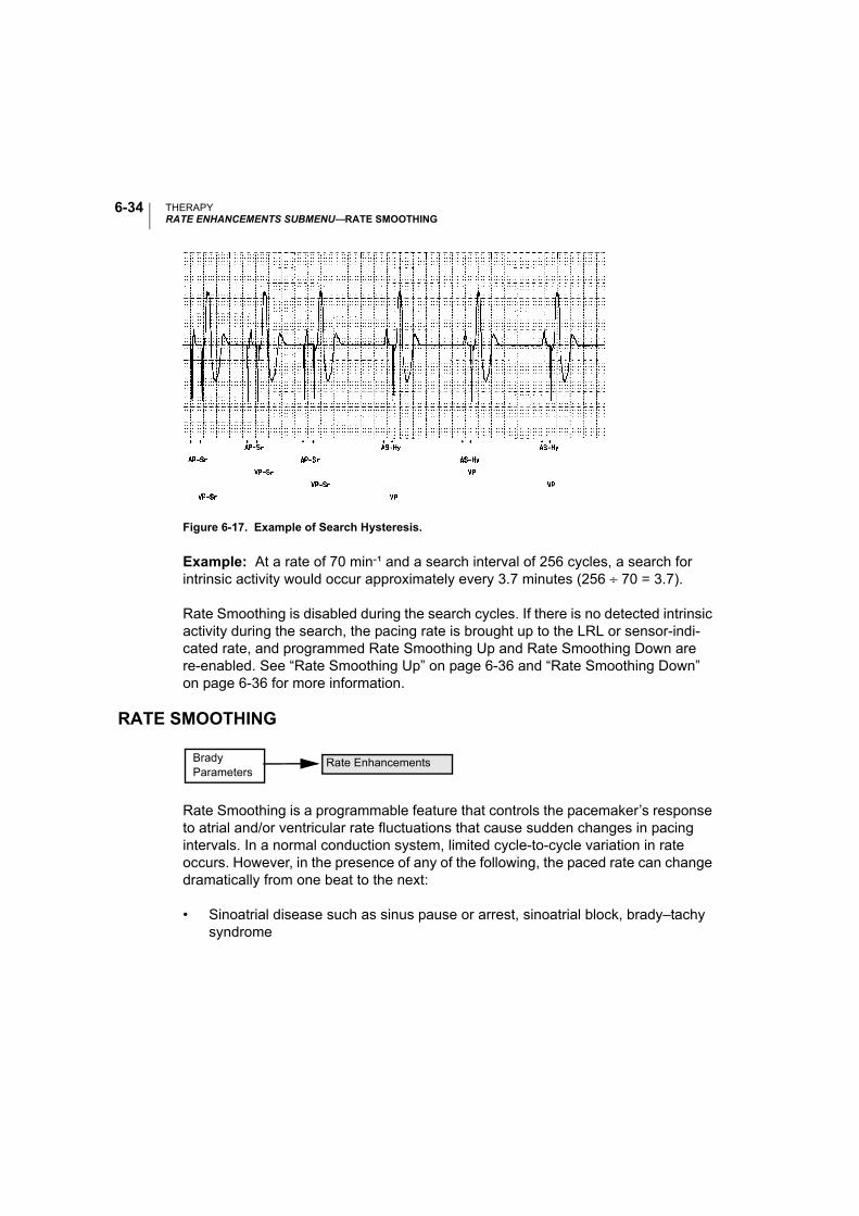
THERAPYRATE ENHANCEMENTS SUBMENU—RATE SMOOTHING
6-34
Figure 6-17. Example of Search Hysteresis.
Example: At a rate of 70 min-¹ and a search interval of 256 cycles, a search for intrinsic activity would occur approximately every 3.7 minutes (256 ÷ 70 = 3.7).
Rate Smoothing is disabled during the search cycles. If there is no detected intrinsic activity during the search, the pacing rate is brought up to the LRL or sensor-indi-cated rate, and programmed Rate Smoothing Up and Rate Smoothing Down are re-enabled. See “Rate Smoothing Up” on page 6-36 and “Rate Smoothing Down” on page 6-36 for more information.
RATE SMOOTHING
Rate Smoothing is a programmable feature that controls the pacemaker’s response to atrial and/or ventricular rate fluctuations that cause sudden changes in pacing intervals. In a normal conduction system, limited cycle-to-cycle variation in rate occurs. However, in the presence of any of the following, the paced rate can change dramatically from one beat to the next:
• Sinoatrial disease such as sinus pause or arrest, sinoatrial block, brady–tachy syndrome
Brady Parameters
Rate Enhancements
THERAPYRATE ENHANCEMENTS SUBMENU—RATE SMOOTHING
6-35
• Premature atrial and/or ventricular contractions (PAC/PVC)
• Pacemaker Wenckebach
• Intermittent, brief, self-terminating supraventricular tachycardias, atrial flutter/fibrillation
• Retrograde conducted P-waves
• Pacemaker sensing of myopotential signals, electromagnetic interference, crosstalk, etc.
Pacemaker patients who experience large variations in their ventricular paced rate can feel symptomatic during these episodes. Rate Smoothing can prevent these sudden rate changes and their accompanying patient symptoms (such as palpita-tions, dyspnea, and dizziness).
Rate Smoothing is an important enhancement of the A-Tachy Response (ATR) fea-ture. Rate Smoothing can significantly reduce rate fluctuations associated with the onset and cessation of atrial arrhythmias.
Rate Smoothing operates between the LRL and the MTR or the Max Pacing Rate (SSI and DDI) in nonadaptive-rate modes. When the sensor is enabled and MSR is higher than MTR, the operational range is from the LRL to the MSR. Rate Smooth-ing is also applicable between the hysteresis rate and LRL when hysteresis is active, except during Search Hysteresis.
When programmed On:
• Programmable Rate Smoothing values are a percentage of the R–R interval (3%–24% in 3% increments) and can be independently programmed for increase or decrease.
• The pacemaker stores in memory the most recent R–R interval. R-waves may be either intrinsic or paced. Based on this R–R interval and the programmed Rate Smoothing value, the pacemaker sets up two synchronization windows for the next cycle-one for the atrium and one for the ventricle.
• Rate Smoothing is functional except:
• During the 8 cycles of Search Hysteresis
THERAPYRATE ENHANCEMENTS SUBMENU—RATE SMOOTHING
6-36
• During ATR Fallback, until fallback reaches ATR Lower Rate Limit or the sensor indicated rate.
• Upon triggering of the PMT Termination algorithm
• Immediately following programmed increases in the LRL
Also, Rate Smoothing cannot be programmed On when Sudden Brady Response is On.
The clinician should ascertain a given patient’s physiologic cycle-to-cycle variation and program the Rate Smoothing parameter to a value that protects against patho-logic interval changes, yet allows physiologic interval changes in response to increases in activity or exercise.
NOTE: Without Rate Smoothing, a sudden, large atrial rate increase (e.g., paroxys-mal atrial tachycardia) will cause a simultaneous sudden increase in the paced ven-tricular rate as high as the programmed MTR. With Rate Smoothing, the ventricular paced rate in response to such a change might not reach the programmed MTR.
Rate Smoothing Up
The Rate Smoothing Up parameter controls the largest increase allowed in the pac-ing rate when the intrinsic or sensor rate is increasing.
Rate Smoothing Down
The Rate Smoothing Down parameter controls the largest decrease allowed in the pacing rate when the intrinsic or sensor rate interval is decreasing.
NOTE: When Rate Smoothing Down is programmed On and Rate Smoothing Up is programmed Off, the pacemaker will automatically prevent fast intrinsic beats (e.g., PVCs) from resetting the Rate Smoothing Down escape rate any faster than 12% per cycle.
Programmable Values: Off, 3–24% (3% increments) (Nominal = Off)
Programmable Values: Off, 3–24% (3% increments) (Nominal = Off)

THERAPYRATE ENHANCEMENTS SUBMENU—RATE SMOOTHING
6-37
Max Pacing Rate (DDI and SSI)
When Rate Smoothing is programmed On in DDI, VVI, or AAI, the Rate Smoothing Up parameter is used only between the hysteresis rate and the LRL. The Rate Smoothing Down parameter requires the programming of a Max Pacing Rate. The Rate Smoothing Down parameter will then be used only between the Max Pacing Rate and the LRL or the hysteresis rate.
Rate Smoothing Example
The pacemaker stores in memory the most recent R–R interval. R-waves may be either intrinsic or paced. Based on this R–R interval and the programmed Rate Smoothing value, the pacemaker sets up two synchronization windows for the next cycle-one for the atrium and one for the ventricle. This synchronization window is defined as follows:
Ventricular synchronization window = Previous R–R interval ± Rate Smoothing value
Atrial synchronization window = (Previous R–R interval ± Rate Smoothing value) – AV Delay
An example of how these two synchronization windows are calculated is illustrated below and in Figure 6-18:
Previous R–R interval = 800 ms
AV Delay = 150 ms
Rate Smoothing Up = 9% Rate Smoothing Down = 6%
Ventricular synchronization window = 800 – 9% to 800 + 6% = 800 ms – 72 ms to 800 ms + 48 ms = 728 ms to 848 ms
Atrial synchronization window = ventricular synchronization window – AV Delay = 728 ms – 150 ms to 848 ms – 150 ms = 578 ms to 698 ms
Programmable Values: 80–185 min-¹ (5-min-¹ increments) (Nominal = 130 min-¹)
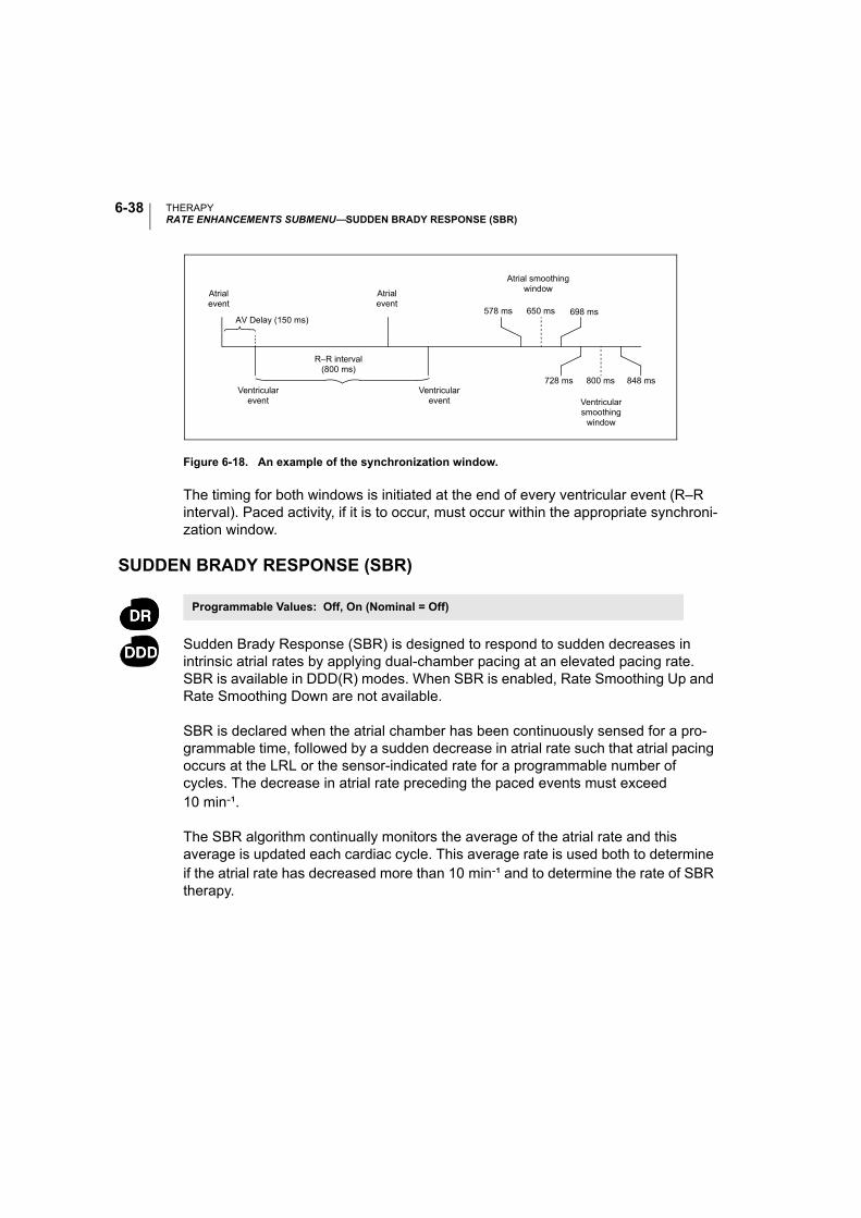
THERAPYRATE ENHANCEMENTS SUBMENU—SUDDEN BRADY RESPONSE (SBR)
6-38
Figure 6-18. An example of the synchronization window.
The timing for both windows is initiated at the end of every ventricular event (R–R interval). Paced activity, if it is to occur, must occur within the appropriate synchroni-zation window.
SUDDEN BRADY RESPONSE (SBR)
Sudden Brady Response (SBR) is designed to respond to sudden decreases in intrinsic atrial rates by applying dual-chamber pacing at an elevated pacing rate. SBR is available in DDD(R) modes. When SBR is enabled, Rate Smoothing Up and Rate Smoothing Down are not available.
SBR is declared when the atrial chamber has been continuously sensed for a pro-grammable time, followed by a sudden decrease in atrial rate such that atrial pacing occurs at the LRL or the sensor-indicated rate for a programmable number of cycles. The decrease in atrial rate preceding the paced events must exceed 10 min-¹.
The SBR algorithm continually monitors the average of the atrial rate and this average is updated each cardiac cycle. This average rate is used both to determine if the atrial rate has decreased more than 10 min-¹ and to determine the rate of SBR therapy.
Atrialevent
Atrialevent
Ventricularevent
R–R interval(800 ms)
Ventricularevent Ventricular
smoothingwindow
AV Delay (150 ms)
Atrial smoothing window
578 ms 650 ms 698 ms
800 ms728 ms 848 ms
Programmable Values: Off, On (Nominal = Off)
THERAPYRATE ENHANCEMENTS SUBMENU—SUDDEN BRADY RESPONSE (SBR)
6-39
SBR Detect Time
SBR Detect Time is the programmable time interval during which the atrium must be 100% sensed.
SBR Number of Beats
The SBR Number of Beats criteria are applied once the decrease in atrial rate has been detected and LRL or sensor-indicated rate pacing has occurred. Atrial pacing must occur for the programmable number of consecutive intervals before the SBR criteria are met, with one exception. A “slow” PVC can count as the first SBR Num-ber of Beats. A “slow” PVC is one that yields a ventricular rate that is ≥ 10 min-¹ slower than the average atrial rate.
SBR Therapy Rate Offset
SBR Therapy Rate Offset is calculated by using the patient’s average atrial rate before the bradycardia and adding a programmable positive offset (Figure 6-19). Pacing is applied in the DDD(R) mode at the greater of either (1) the previous aver-age atrial rate plus the SBR Therapy Rate Offset, not to exceed the MTR, or (2) the sensor-indicated rate (DDDR mode only).
Programmable Values: 1–15 minutes (increments of 1 minute) (Nominal = 5 minutes)
Programmable Values: 1–8 cycles (increments of 1 cycle) (Nominal = 4 cycles)
Programmable Values: 5–40 min-¹ (increments of 5-min-¹) (Nominal = 5 min-¹)
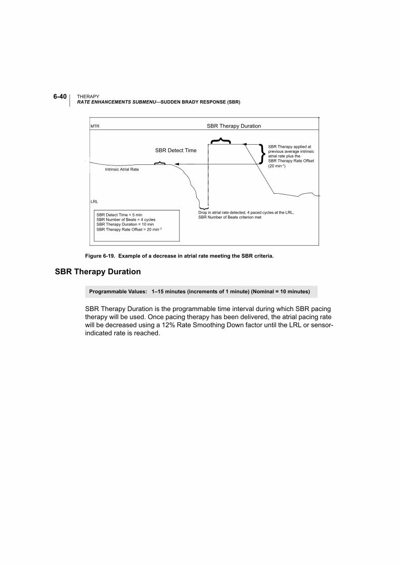
THERAPYRATE ENHANCEMENTS SUBMENU—SUDDEN BRADY RESPONSE (SBR)
6-40
Figure 6-19. Example of a decrease in atrial rate meeting the SBR criteria.
SBR Therapy Duration
SBR Therapy Duration is the programmable time interval during which SBR pacing therapy will be used. Once pacing therapy has been delivered, the atrial pacing rate will be decreased using a 12% Rate Smoothing Down factor until the LRL or sensor-indicated rate is reached.
Intrinsic Atrial Rate
LRL
Drop in atrial rate detected, 4 paced cycles at the LRL, SBR Number of Beats criterion met
SBR Therapy applied at previous average intrinsic atrial rate plus theSBR Therapy Rate Offset (20 min-¹)
MTR
SBR Detect Time = 5 minSBR Number of Beats = 4 cyclesSBR Therapy Duration = 10 minSBR Therapy Rate Offset = 20 min-1
}
}
}
SBR Therapy Duration
}SBR Detect Time
Programmable Values: 1–15 minutes (increments of 1 minute) (Nominal = 10 minutes)
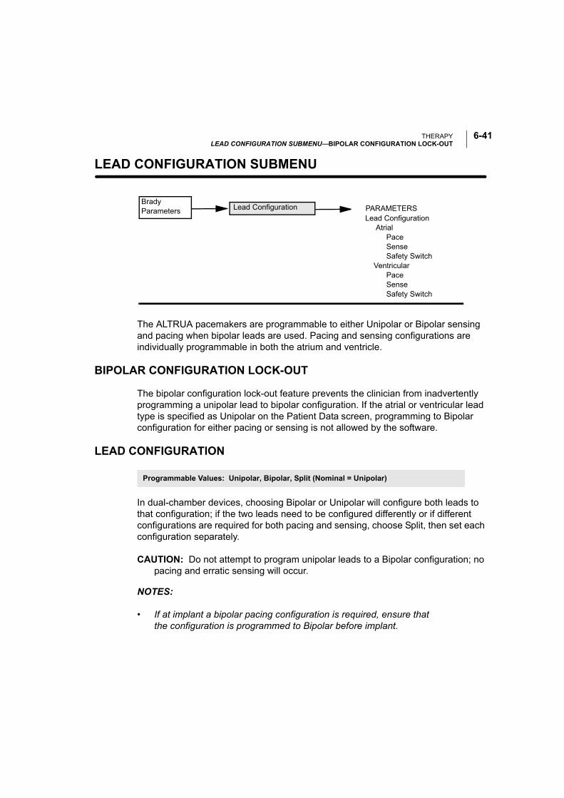
THERAPYLEAD CONFIGURATION SUBMENU—BIPOLAR CONFIGURATION LOCK-OUT
6-41
LEAD CONFIGURATION SUBMENU—
The ALTRUA pacemakers are programmable to either Unipolar or Bipolar sensing and pacing when bipolar leads are used. Pacing and sensing configurations are individually programmable in both the atrium and ventricle.
BIPOLAR CONFIGURATION LOCK-OUT
The bipolar configuration lock-out feature prevents the clinician from inadvertently programming a unipolar lead to bipolar configuration. If the atrial or ventricular lead type is specified as Unipolar on the Patient Data screen, programming to Bipolar configuration for either pacing or sensing is not allowed by the software.
LEAD CONFIGURATION
In dual-chamber devices, choosing Bipolar or Unipolar will configure both leads to that configuration; if the two leads need to be configured differently or if different configurations are required for both pacing and sensing, choose Split, then set each configuration separately.
CAUTION: Do not attempt to program unipolar leads to a Bipolar configuration; no pacing and erratic sensing will occur.
NOTES:
• If at implant a bipolar pacing configuration is required, ensure that the configuration is programmed to Bipolar before implant.
Brady Parameters
Lead Configuration Atrial Pace Sense Safety Switch Ventricular Pace Sense Safety Switch
PARAMETERSLead Configuration
Programmable Values: Unipolar, Bipolar, Split (Nominal = Unipolar)
THERAPYLEAD CONFIGURATION SUBMENU—SAFETY SWITCH (AUTOMATIC LEAD CONFIGURATION)
6-42
• If the clinician selects Unipolar for the atrial or ventricular lead on the Patient Data screen, the application will not allow that lead configuration to be pro-grammed to Bipolar.
Pacing Configuration
When the unipolar pacing configuration is programmed, the pacing stimulus will be applied between the lead tip and the pacemaker case. In the bipolar pacing configu-ration, the stimulus will be applied between the lead tip and the lead ring.
In the unipolar pacing configuration, the pacing artifact should be clearly visible on the surface ECG, which will assist in its interpretation. However, unipolar pacing at high outputs is more likely than bipolar pacing to cause muscle stimulation.
Sensing Configuration
When the unipolar sensing configuration is programmed, the cardiac signals are detected between the lead tip and the pacemaker case. In the unipolar sensing con-figuration, the pacemaker can generally discern smaller intrinsic cardiac signals than in the bipolar configuration. However, the unipolar configuration is also more sensitive to myopotentials.
In bipolar configurations, because of the relatively short distance between the tip and ring electrodes, sensitivity is highest for signals originating in the proximity of the lead tip and ring. As a result, the pacemaker is less likely to sense myopotentials and other signals unrelated to cardiac depolarization.
SAFETY SWITCH (AUTOMATIC LEAD CONFIGURATION)
The Safety Switch feature allows the pacemaker to monitor lead integrity and to switch the pacing and sensing configuration from bipolar to unipolar if the imped-ance criteria indicate unacceptably high or low lead impedances.
The pacemaker monitors lead integrity daily by measuring lead impedance during paced events. When the Safety Switch feature is programmed On in either the atrium or the ventricle and the measured impedance falls outside the 100–2500 Ω range for any daily measurement, both pacing and sensing configurations will auto-matically be switched to Unipolar for that chamber. Once the configuration has
Programmable Values: On, Off, Reset (Nominal = Off)

THERAPYLEAD CONFIGURATION SUBMENU—SAFETY SWITCH (AUTOMATIC LEAD CONFIGURATION)
6-43
switched, it will remain Unipolar. Select Reset for the Safety Switch to clear the switched indication.
CAUTION: If high-impedance leads with measured values approaching 2500 Ω are used, consider programming the Safety Switch Off.
WARNING: In devices with the Safety Switch programmed to On, the lead polarity will revert to Unipolar in the presence of a lead impedance of < 100 Ω or > 2500 Ω. Unipolar pacing is contraindicated for patients with an ICD.
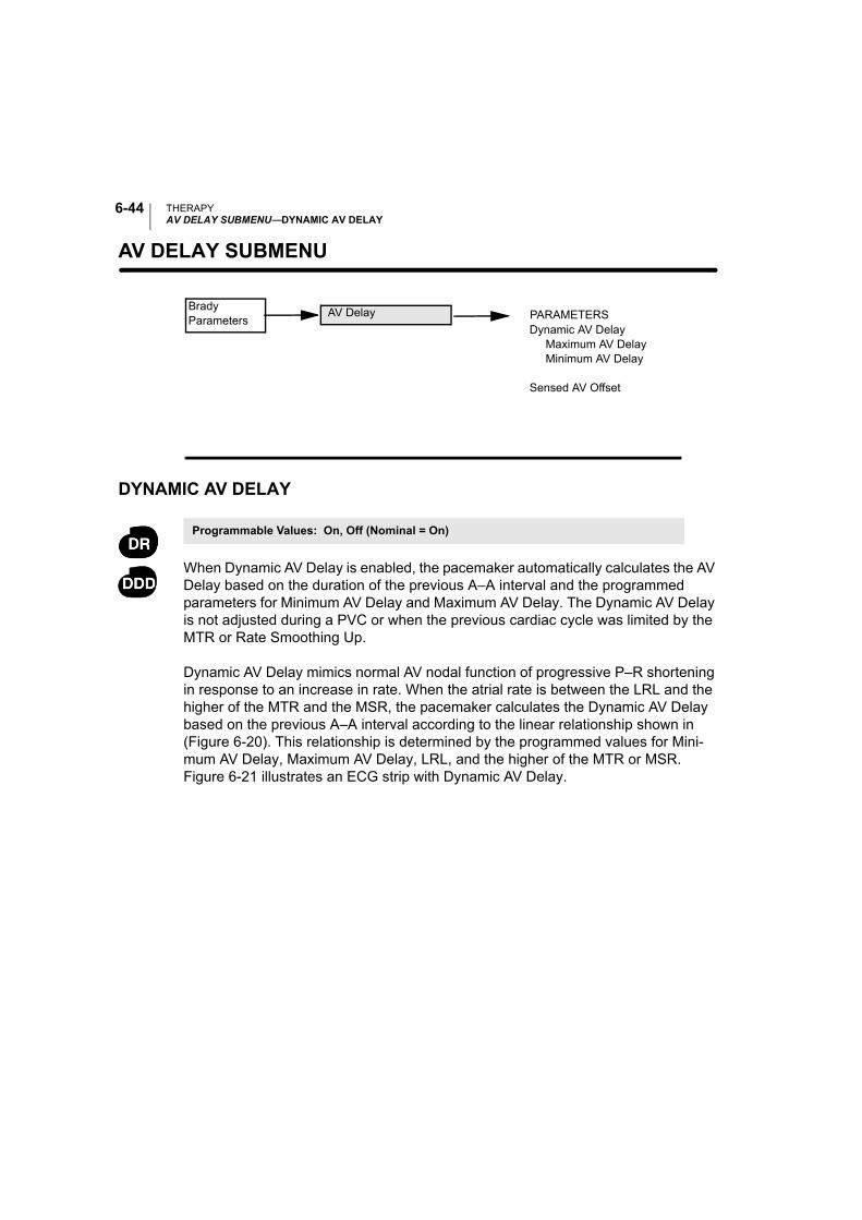
THERAPYAV DELAY SUBMENU—DYNAMIC AV DELAY
6-44
AV DELAY SUBMENU—
DYNAMIC AV DELAY
When Dynamic AV Delay is enabled, the pacemaker automatically calculates the AV Delay based on the duration of the previous A–A interval and the programmed parameters for Minimum AV Delay and Maximum AV Delay. The Dynamic AV Delay is not adjusted during a PVC or when the previous cardiac cycle was limited by the MTR or Rate Smoothing Up.
Dynamic AV Delay mimics normal AV nodal function of progressive P–R shortening in response to an increase in rate. When the atrial rate is between the LRL and the higher of the MTR and the MSR, the pacemaker calculates the Dynamic AV Delay based on the previous A–A interval according to the linear relationship shown in (Figure 6-20). This relationship is determined by the programmed values for Mini-mum AV Delay, Maximum AV Delay, LRL, and the higher of the MTR or MSR. Figure 6-21 illustrates an ECG strip with Dynamic AV Delay.
Brady Parameters
Dynamic AV Delay Maximum AV Delay Minimum AV Delay
Sensed AV Offset
PARAMETERSAV Delay
Programmable Values: On, Off (Nominal = On)
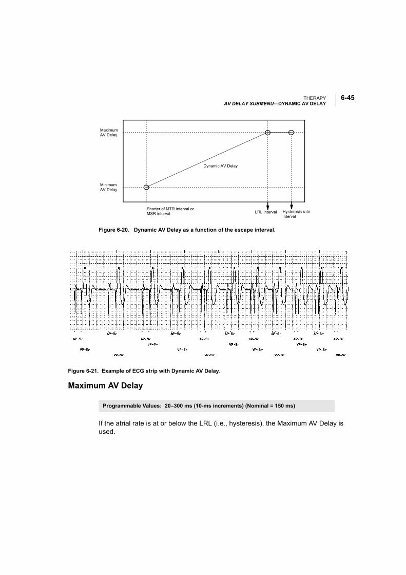
THERAPYAV DELAY SUBMENU—DYNAMIC AV DELAY
6-45
Figure 6-20. Dynamic AV Delay as a function of the escape interval.
Maximum AV Delay
If the atrial rate is at or below the LRL (i.e., hysteresis), the Maximum AV Delay is used.
Maximum AV Delay
Minimum AV Delay
Shorter of MTR interval or MSR interval LRL interval Hysteresis rate
interval
Dynamic AV Delay
Figure 6-21. Example of ECG strip with Dynamic AV Delay.
Programmable Values: 20–300 ms (10-ms increments) (Nominal = 150 ms)
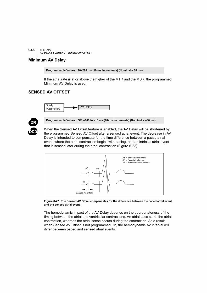
THERAPYAV DELAY SUBMENU—SENSED AV OFFSET
6-46
Minimum AV Delay
If the atrial rate is at or above the higher of the MTR and the MSR, the programmed Minimum AV Delay is used.
SENSED AV OFFSET
When the Sensed AV Offset feature is enabled, the AV Delay will be shortened by the programmed Sensed AV Offset after a sensed atrial event. The decrease in AV Delay is intended to compensate for the time difference between a paced atrial event, where the atrial contraction begins with pacing, and an intrinsic atrial event that is sensed later during the atrial contraction (Figure 6-22).
Figure 6-22. The Sensed AV Offset compensates for the difference between the paced atrial event and the sensed atrial event.
The hemodynamic impact of the AV Delay depends on the appropriateness of the timing between the atrial and ventricular contractions. An atrial pace starts the atrial contraction, whereas the atrial sense occurs during the contraction. As a result, when Sensed AV Offset is not programmed On, the hemodynamic AV interval will differ between paced and sensed atrial events.
Programmable Values: 10–290 ms (10-ms increments) (Nominal = 80 ms)
Programmable Values: Off, –100 to –10 ms (10-ms increments) (Nominal = –30 ms)
Brady Parameters
AV Delay
AS
AP
AS = Sensed atrial eventAP = Paced atrial eventVP = Paced ventricular event
VP
Sensed AV Offset
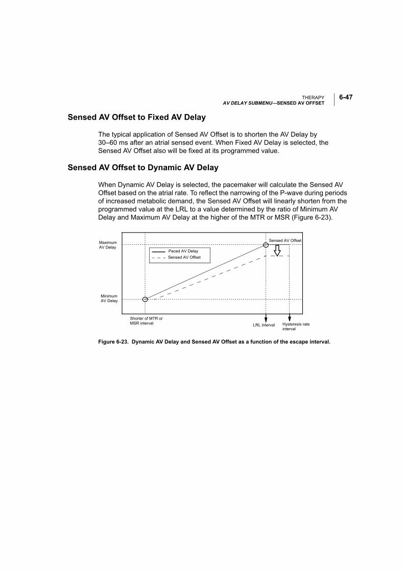
THERAPYAV DELAY SUBMENU—SENSED AV OFFSET
6-47
Sensed AV Offset to Fixed AV Delay
The typical application of Sensed AV Offset is to shorten the AV Delay by 30–60 ms after an atrial sensed event. When Fixed AV Delay is selected, the Sensed AV Offset also will be fixed at its programmed value.
Sensed AV Offset to Dynamic AV Delay
When Dynamic AV Delay is selected, the pacemaker will calculate the Sensed AV Offset based on the atrial rate. To reflect the narrowing of the P-wave during periods of increased metabolic demand, the Sensed AV Offset will linearly shorten from the programmed value at the LRL to a value determined by the ratio of Minimum AV Delay and Maximum AV Delay at the higher of the MTR or MSR (Figure 6-23).
Figure 6-23. Dynamic AV Delay and Sensed AV Offset as a function of the escape interval.
Maximum AV Delay
Sensed AV Offset
Minimum AV Delay
Shorter of MTR or MSR interval LRL interval Hysteresis rate
interval
Paced AV Delay
Sensed AV Offset
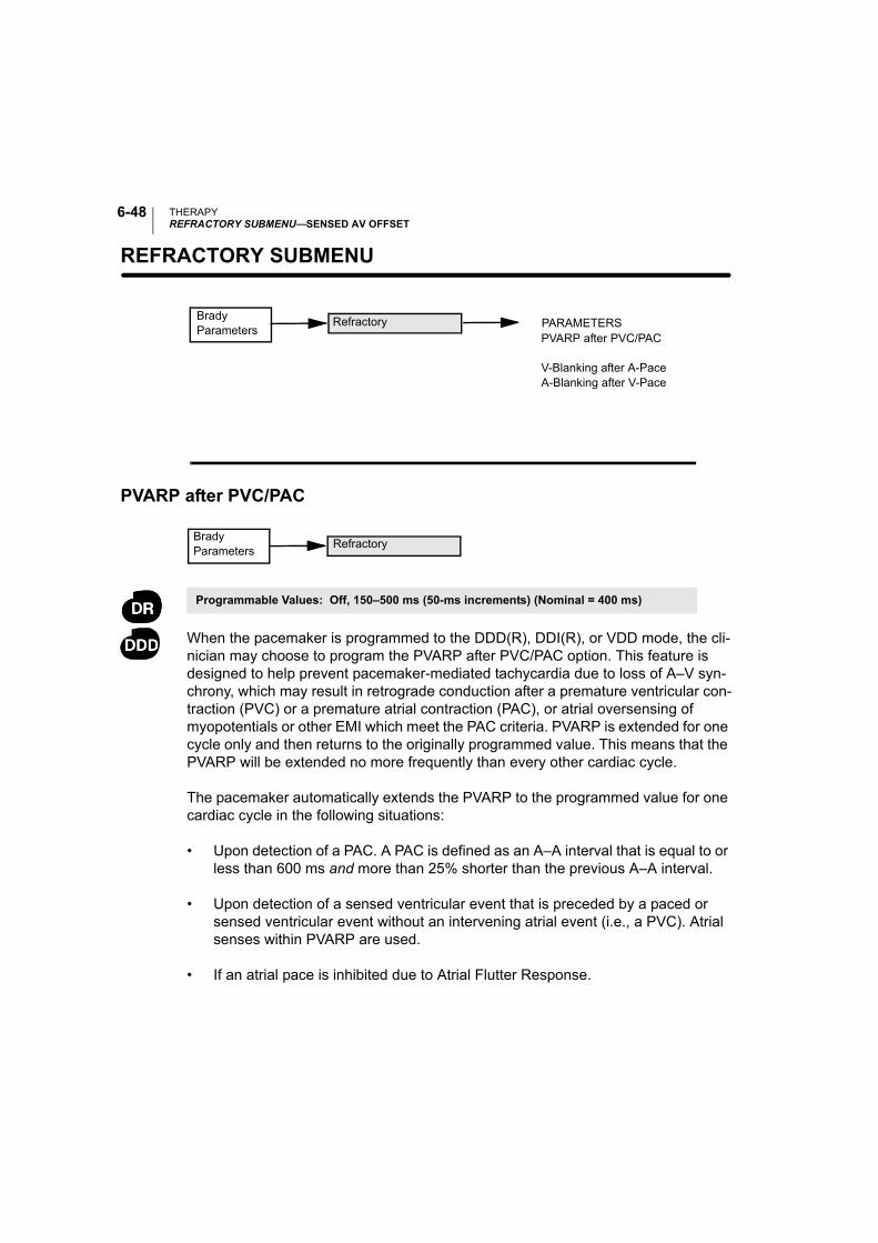
THERAPYREFRACTORY SUBMENU—SENSED AV OFFSET
6-48
REFRACTORY SUBMENU—
PVARP after PVC/PAC
When the pacemaker is programmed to the DDD(R), DDI(R), or VDD mode, the cli-nician may choose to program the PVARP after PVC/PAC option. This feature is designed to help prevent pacemaker-mediated tachycardia due to loss of A–V syn-chrony, which may result in retrograde conduction after a premature ventricular con-traction (PVC) or a premature atrial contraction (PAC), or atrial oversensing of myopotentials or other EMI which meet the PAC criteria. PVARP is extended for one cycle only and then returns to the originally programmed value. This means that the PVARP will be extended no more frequently than every other cardiac cycle.
The pacemaker automatically extends the PVARP to the programmed value for one cardiac cycle in the following situations:
• Upon detection of a PAC. A PAC is defined as an A–A interval that is equal to or less than 600 ms and more than 25% shorter than the previous A–A interval.
• Upon detection of a sensed ventricular event that is preceded by a paced or sensed ventricular event without an intervening atrial event (i.e., a PVC). Atrial senses within PVARP are used.
• If an atrial pace is inhibited due to Atrial Flutter Response.
Brady Parameters
PVARP after PVC/PAC
V-Blanking after A-PaceA-Blanking after V-Pace
PARAMETERSRefractory
Programmable Values: Off, 150–500 ms (50-ms increments) (Nominal = 400 ms)
Brady Parameters
Refractory
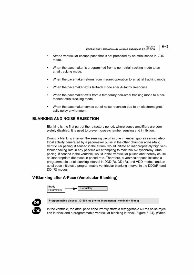
THERAPYREFRACTORY SUBMENU—BLANKING AND NOISE REJECTION
6-49
• After a ventricular escape pace that is not preceded by an atrial sense in VDD mode.
• When the pacemaker is programmed from a non-atrial tracking mode to an atrial tracking mode.
• When the pacemaker returns from magnet operation to an atrial tracking mode.
• When the pacemaker exits fallback mode after A-Tachy Response.
• When the pacemaker exits from a temporary non-atrial tracking mode to a per-manent atrial tracking mode.
• When the pacemaker comes out of noise reversion due to an electromagneti-cally noisy environment.
BLANKING AND NOISE REJECTION
Blanking is the first part of the refractory period, where sense amplifiers are com-pletely disabled. It is used to prevent cross-chamber sensing and inhibition.
During a blanking interval, the sensing circuit in one chamber ignores sensed elec-trical activity generated by a pacemaker pulse in the other chamber (cross-talk). Ventricular pacing, if sensed in the atrium, would initiate an inappropriately high ven-tricular pacing rate in any pacemaker attempting to maintain AV synchrony. Atrial pacing, if sensed in the ventricle, would inhibit ventricular pulses and thereby cause an inappropriate decrease in paced rate. Therefore, a ventricular pace initiates a programmable atrial blanking interval in DDD(R), DDI(R), and VDD modes, and an atrial pace initiates a programmable ventricular blanking interval in the DDD(R) and DDI(R) modes.
V-Blanking after A-Pace (Ventricular Blanking)
In the ventricle, the atrial pace concurrently starts a retriggerable 60-ms noise rejec-tion interval and a programmable ventricular blanking interval (Figure 6-24). (When-
Programmable Values: 30–200 ms (10-ms increments) (Nominal = 40 ms)
Brady Parameters
Refractory
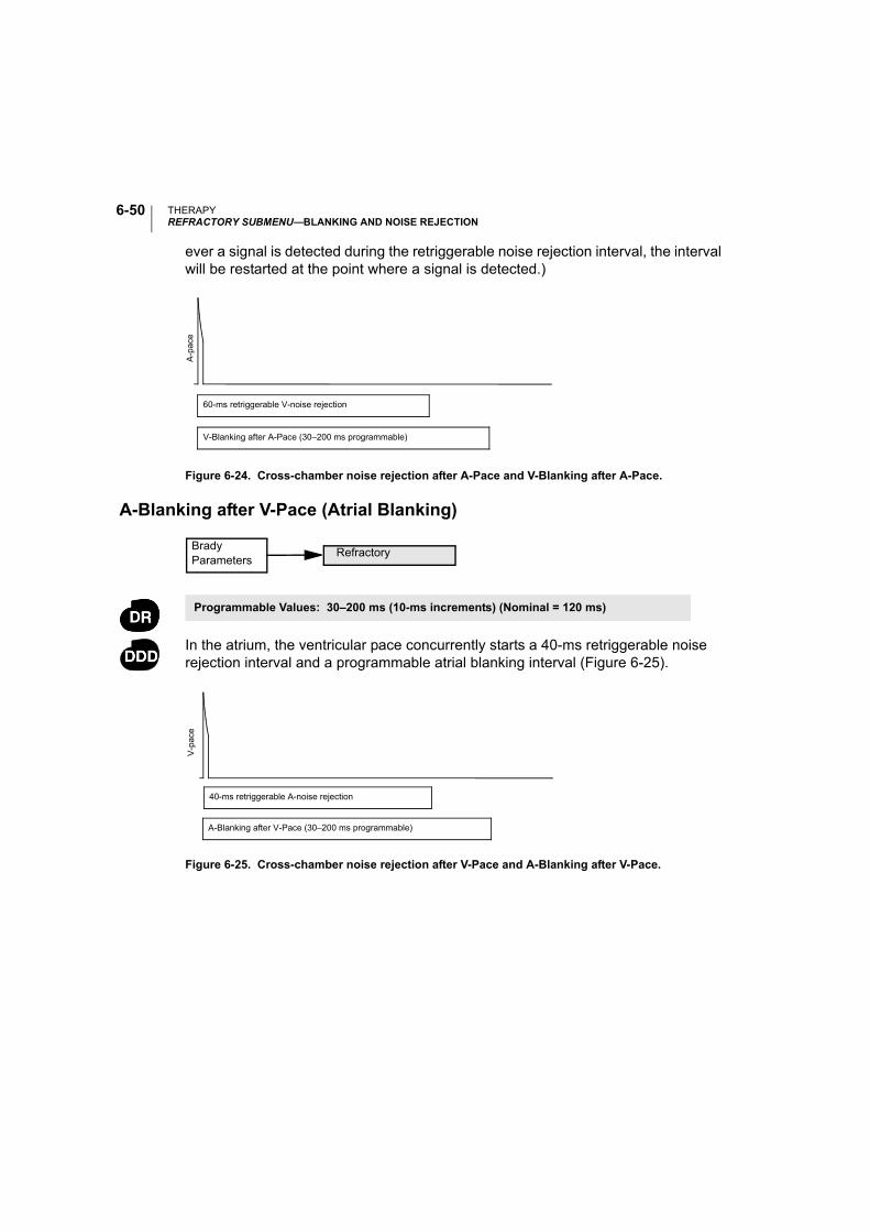
THERAPYREFRACTORY SUBMENU—BLANKING AND NOISE REJECTION
6-50
ever a signal is detected during the retriggerable noise rejection interval, the interval will be restarted at the point where a signal is detected.)
Figure 6-24. Cross-chamber noise rejection after A-Pace and V-Blanking after A-Pace.
A-Blanking after V-Pace (Atrial Blanking)
In the atrium, the ventricular pace concurrently starts a 40-ms retriggerable noise rejection interval and a programmable atrial blanking interval (Figure 6-25).
Figure 6-25. Cross-chamber noise rejection after V-Pace and A-Blanking after V-Pace.
A-p
ace
V-Blanking after A-Pace (30–200 ms programmable)
60-ms retriggerable V-noise rejection
Programmable Values: 30–200 ms (10-ms increments) (Nominal = 120 ms)
Brady Parameters
Refractory
A-Blanking after V-Pace (30–200 ms programmable)
40-ms retriggerable A-noise rejection
V-p
ace
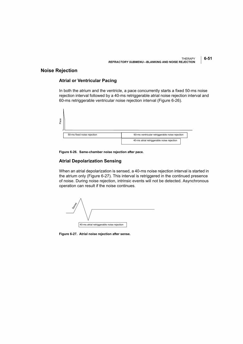
THERAPYREFRACTORY SUBMENU—BLANKING AND NOISE REJECTION
6-51
Noise Rejection
Atrial or Ventricular Pacing
In both the atrium and the ventricle, a pace concurrently starts a fixed 50-ms noise rejection interval followed by a 40-ms retriggerable atrial noise rejection interval and 60-ms retriggerable ventricular noise rejection interval (Figure 6-26).
Figure 6-26. Same-chamber noise rejection after pace.
Atrial Depolarization Sensing
When an atrial depolarization is sensed, a 40-ms noise rejection interval is started in the atrium only (Figure 6-27). This interval is retriggered in the continued presence of noise. During noise rejection, intrinsic events will not be detected. Asynchronous operation can result if the noise continues.
Figure 6-27. Atrial noise rejection after sense.
Pac
e
60-ms ventricular retriggerable noise rejection50-ms fixed noise rejection
40-ms atrial retriggerable noise rejection
40-ms atrial retriggerable noise rejection
Sen
se
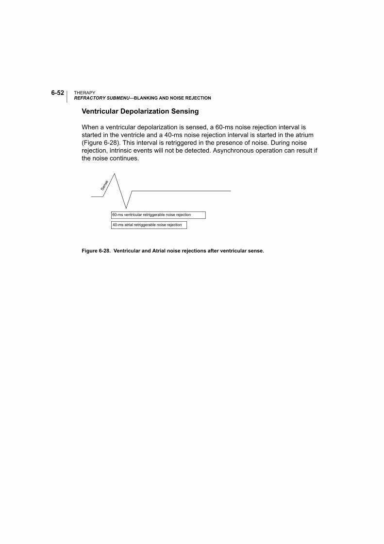
THERAPYREFRACTORY SUBMENU—BLANKING AND NOISE REJECTION
6-52
Ventricular Depolarization Sensing
When a ventricular depolarization is sensed, a 60-ms noise rejection interval is started in the ventricle and a 40-ms noise rejection interval is started in the atrium (Figure 6-28). This interval is retriggered in the presence of noise. During noise rejection, intrinsic events will not be detected. Asynchronous operation can result if the noise continues.
Figure 6-28. Ventricular and Atrial noise rejections after ventricular sense.
60-ms ventricular retriggerable noise rejection
40-ms atrial retriggerable noise rejection
Sen
se
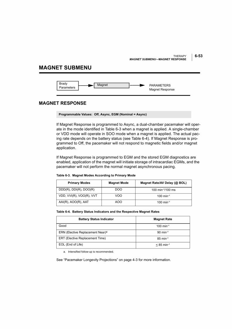
THERAPYMAGNET SUBMENU—MAGNET RESPONSE
6-53
MAGNET SUBMENU—
MAGNET RESPONSE
If Magnet Response is programmed to Async, a dual-chamber pacemaker will oper-ate in the mode identified in Table 6-3 when a magnet is applied. A single-chamber or VDD mode will operate in SOO mode when a magnet is applied. The actual pac-ing rate depends on the battery status (see Table 6-4). If Magnet Response is pro-grammed to Off, the pacemaker will not respond to magnetic fields and/or magnet application.
If Magnet Response is programmed to EGM and the stored EGM diagnostics are enabled, application of the magnet will initiate storage of intracardiac EGMs, and the pacemaker will not perform the normal magnet asynchronous pacing.
See “Pacemaker Longevity Projections” on page 4-3 for more information.
Brady Parameters
PARAMETERSMagnet Response
Magnet
Programmable Values: Off, Async, EGM (Nominal = Async)
Table 6-3. Magnet Modes According to Primary Mode
Primary Modes Magnet Mode Magnet Rate/AV Delay (@ BOL)
DDD(R), DDI(R), DOO(R) DOO 100 min-¹/100 ms
VDD, VVI(R), VOO(R), VVT VOO 100 min-¹
AAI(R), AOO(R), AAT AOO 100 min-¹
Table 6-4. Battery Status Indicators and the Respective Magnet Rates
Battery Status Indicator Magnet Rate
Good 100 min-¹
ERN (Elective Replacement Near)a
a. Intensified follow-up is recommended.
90 min-¹
ERT (Elective Replacement Time) 85 min-¹
EOL (End of Life) < 85 min-¹

THERAPYMAGNET SUBMENU—MAGNET RESPONSE
6-54
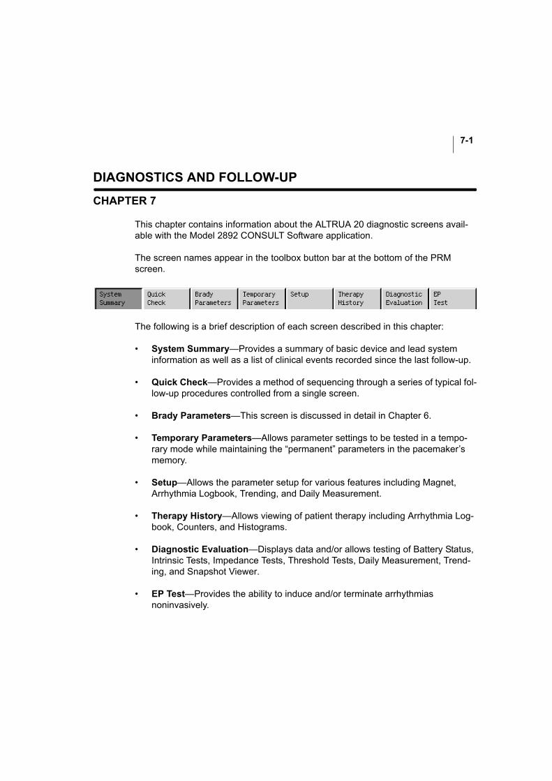
7-1
DIAGNOSTICS AND FOLLOW-UP
CHAPTER 7
This chapter contains information about the ALTRUA 20 diagnostic screens avail-able with the Model 2892 CONSULT Software application.
The screen names appear in the toolbox button bar at the bottom of the PRM screen.
The following is a brief description of each screen described in this chapter:
• System Summary—Provides a summary of basic device and lead system information as well as a list of clinical events recorded since the last follow-up.
• Quick Check—Provides a method of sequencing through a series of typical fol-low-up procedures controlled from a single screen.
• Brady Parameters—This screen is discussed in detail in Chapter 6.
• Temporary Parameters—Allows parameter settings to be tested in a tempo-rary mode while maintaining the “permanent” parameters in the pacemaker’s memory.
• Setup—Allows the parameter setup for various features including Magnet, Arrhythmia Logbook, Trending, and Daily Measurement.
• Therapy History—Allows viewing of patient therapy including Arrhythmia Log-book, Counters, and Histograms.
• Diagnostic Evaluation—Displays data and/or allows testing of Battery Status, Intrinsic Tests, Impedance Tests, Threshold Tests, Daily Measurement, Trend-ing, and Snapshot Viewer.
• EP Test—Provides the ability to induce and/or terminate arrhythmias noninvasively.
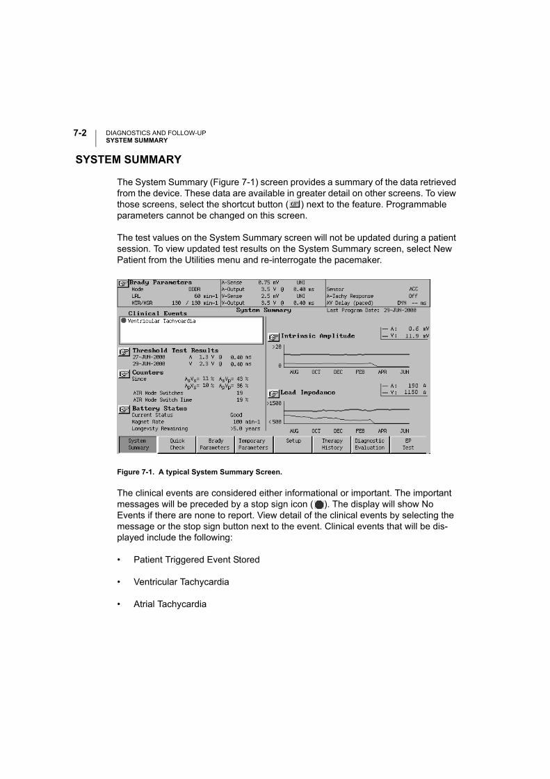
DIAGNOSTICS AND FOLLOW-UPSYSTEM SUMMARY
7-2
SYSTEM SUMMARY
The System Summary (Figure 7-1) screen provides a summary of the data retrieved from the device. These data are available in greater detail on other screens. To view those screens, select the shortcut button ( ) next to the feature. Programmable parameters cannot be changed on this screen.
The test values on the System Summary screen will not be updated during a patient session. To view updated test results on the System Summary screen, select New Patient from the Utilities menu and re-interrogate the pacemaker.
Figure 7-1. A typical System Summary Screen.
The clinical events are considered either informational or important. The important messages will be preceded by a stop sign icon ( ). The display will show No Events if there are none to report. View detail of the clinical events by selecting the message or the stop sign button next to the event. Clinical events that will be dis-played include the following:
• Patient Triggered Event Stored
• Ventricular Tachycardia
• Atrial Tachycardia
DIAGNOSTICS AND FOLLOW-UPQUICK CHECK SCREEN
7-3
• Lead Configuration Switched
• Battery at ERT
• Battery at EOL
• PMT Episode Stored
• Sudden Brady Response
• Patient Activated EGMs On
QUICK CHECK SCREEN
The Quick Check screen (Figure 7-2) provides a method of sequencing through a series of follow-up procedures. The selected tests will be performed in the order they appear on the screen, beginning with the left column when the Start button is depressed. The clinician will be prompted with a dialogue window before each of the following tests: Intrinsic Amplitude Measurement, Lead Impedance Measurement, and Amplitude Threshold Tests. After the Amplitude Threshold Tests, no messages are displayed other than Telemetry in Progress.
Beside each function on the Quick Check screen is a Go button . Individual func-tions can be activated by depressing the Go button. This allows the user to repeat individual Quick Check functions or perform the tests in any sequence desired. As each test is completed, the results are displayed on the screen.
If a test was unable to complete (e.g., patient was 100% paced during Intrinsic Amplitude Measurement), the results will be reported as NR (no result).
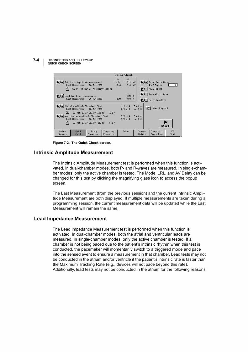
DIAGNOSTICS AND FOLLOW-UPQUICK CHECK SCREEN
7-4
Figure 7-2. The Quick Check screen.
Intrinsic Amplitude Measurement
The Intrinsic Amplitude Measurement test is performed when this function is acti-vated. In dual-chamber modes, both P- and R-waves are measured. In single-cham-ber modes, only the active chamber is tested. The Mode, LRL, and AV Delay can be changed for this test by clicking the magnifying glass icon to access the popup screen.
The Last Measurement (from the previous session) and the current Intrinsic Ampli-tude Measurement are both displayed. If multiple measurements are taken during a programming session, the current measurement data will be updated while the Last Measurement will remain the same.
Lead Impedance Measurement
The Lead Impedance Measurement test is performed when this function is activated. In dual-chamber modes, both the atrial and ventricular leads are measured. In single-chamber modes, only the active chamber is tested. If a chamber is not being paced due to the patient’s intrinsic rhythm when this test is conducted, the pacemaker will momentarily switch to a triggered mode and pace into the sensed event to ensure a measurement in that chamber. Lead tests may not be conducted in the atrium and/or ventricle if the patient's intrinsic rate is faster than the Maximum Tracking Rate (e.g., devices will not pace beyond this rate). Additionally, lead tests may not be conducted in the atrium for the following reasons:
DIAGNOSTICS AND FOLLOW-UPQUICK CHECK SCREEN
7-5
• In DDD(R) mode, if the pacemaker has ATR mode switched to a non-atrial pac-ing mode (e.g., VDI) due to an atrial arrhythmia, pacing will not be delivered.
• If the Atrial Flutter Response feature is programmed ON and is active during an atrial flutter.
The Last Measurement (from the previous session) and the current Lead Imped-ance Measurement are both displayed. If multiple measurements are taken during a programming session, the current measurement data will be updated while the Last Measurement will remain the same.
If you are unable to obtain a successful lead impedance measurement, consider the following temporary programming options as appropriate for each patient:
• increase the Lower Rate Limit above the patient’s intrinsic rhythm,
• decrease the AV Delay to increase the chance that a ventricular pace occurs prior to an intrinsic/conducted ventricular contraction,
• program the device to an asynchronous mode (e.g., DOO, AOO or VOO), or
• program the device to a single-chamber mode (e.g., AAI or VVI) or triggered mode (e.g., AAT or VVT).
Atrial and Ventricular Amplitude Threshold Test
The Atrial Amplitude Threshold Test and the Ventricular Amplitude Threshold Test use the Smart Start amplitude value, which is three voltage steps above the previ-ously measured threshold. If there has not been a previous threshold, the test will start at the programmed voltage. The LRL, AV Delay, and starting voltage amplitude can be changed for this test by accessing the popup screen with the magnifying glass icon. The surface ECG is automatically set to 2X for the duration of the Atrial Amplitude Threshold Test to help the user distinguish the P-wave. Only the thresh-old tests require intervention: the clinician is prompted to remove the telemetry wand or select Stop at loss of capture. When the user stops the test the Snapshot Viewer will automatically be activated and the 10 seconds before loss of capture will be recorded. This information, as well as the Amplitude and Pulse Width settings, can be viewed and printed from the Snapshot Viewer screen.
The Last Measurement (from the previous session) and the current Intrinsic Ampli-tude Measurement are both displayed. If multiple measurements are taken, the cur-rent measurement data will be updated while the Last Measurement will remain the
DIAGNOSTICS AND FOLLOW-UPBRADY PARAMETERS SCREEN
7-6
same. The threshold measurement displayed is the voltage step value that is one higher than when the threshold test was terminated.
NOTE: The Ventricular Amplitude Threshold Test begins immediately after the completion of the Atrial Amplitude Threshold Test.
Print Quick Notes
Quick Notes provides a summary of the Quick Check test results. One to 5 copies can be printed.
Full Report
A summary that includes Quick Check test results, Brady Parameters, Battery Sta-tus, Histograms, Counters, Daily Measurement, and Arrhythmia Logbook may be printed using the Full Report function.
Save All to Disk
Patient and device data can be saved to a data disk. The data from only one patient’s device can be stored on a single disk; information from multiple devices cannot be stored on the same data disk.
Reset Counters
The event counters can be reset via telemetry by selecting the Reset Counters but-ton. Use caution when performing this operation. Once telemetry is established, some or all of the data will be cleared even if you choose the Cancel button during the operation. Pacing mode changes do not reset the event counters.
BRADY PARAMETERS SCREEN
The Brady Parameters screen and the submenus accessible through it are dis-cussed on page 6-5.

DIAGNOSTICS AND FOLLOW-UPTEMPORARY PARAMETERS SCREEN
7-7
TEMPORARY PARAMETERS SCREEN
The pacemaker can be programmed with temporary parameter values that differ from the programmed “permanent” values. This allows the clinician to examine alternate pacing therapies while maintaining the previously programmed permanent parameters in the pacemaker memory. Once initiated, temporary programming remains in effect as long as telemetry is maintained between the programmer and the pacemaker. The Temporary Parameters are deactivated and the permanent parameters are restored when the telemetry link is broken or when the Cancel but-ton is selected on the Temporary Parameters Now in Use window.
NOTE: When the pacemaker is transmitting real-time EGMs or is in Temporary Parameters mode, some diagnostic functions are suspended. This includes Trending, Counters, and Histograms. When the pacemaker is in magnet mode, sensor and rate trending are suspended.
Parameters and range values that are available during permanent programming are also available during Temporary programming with the exception of the following features:
• Magnet
• Lead Safety Switch
In addition, Temporary programming offers nonpacing modes and values that are not available in permanent programming (see Appendix C for listing). Unlike the per-manent parameters, Temporary programming permits Amplitude to be turned Off. This allows examination of underlying cardiac rhythms.
CAUTION: If the Amplitude is Off during Temporary programming, the pacemaker will not pace. Pacing with the permanently programmed parameters can be restored by breaking the telemetry link or by selecting the Cancel button on the Temporary Parameters Now in Use window.
Implementing Temporary Values
Use the following procedure to program the pacemaker for temporary pacing:

DIAGNOSTICS AND FOLLOW-UPTEMPORARY PARAMETERS SCREEN
7-8
1. Select the Temporary Parameters button on the tool bar.
NOTE: If a report is desired listing the Temporary Parameters, select the Printer icon and make sure that Print after Modification is set to Enable. The report will print after the Temporary programming session has ended.
2. Select the parameter to change by clicking on the Temporary box next to the parameter.
3. Select new parameter values. If additional parameters require modification, repeat to achieve the desired values. Multiple parameter changes can be made at one time.
After entering the change(s), make sure that the Parameter Interaction button is not displayed. If it is, select that button to determine how the current changes violate interactive limits. Any interactive limit errors ( ) must be corrected before Temporary programming can occur. Interactive limit warnings ( ) should be taken into careful consideration before continuing, but will not prohibit programming.
4. Press the Start button to send the changes to the pacemaker via telemetry. The PRM will display a window indicating that Temporary programming is in effect. As long as the telemetry link is maintained, the pacemaker will function accord-ing to the Temporary values. No changes can be made to permanent parameters while in a Temporary programming mode.
5. To end Temporary programming, press the Cancel button on the Temporary pro-gramming window or break the telemetry link. The pacemaker will then return to using the permanent pacing parameters.
After a Temporary programming session, you can perform any of the following actions:
• Make additional changes to the Temporary Parameters for further examination.
• Copy the Temporary parameter values to the Change column on the Brady Parameters screen.
• Choose Cancel Changes. This will clear the Temporary values from the Tempo-rary column.

DIAGNOSTICS AND FOLLOW-UPSETUP
7-9
SETUP
The Setup screen allows access to the setup and/or reset parameters for the follow-ing features:
• Magnet
• Arrhythmia Logbook
• Trending
• Daily Measurement
Magnet
Select the Magnet button from the Setup tool kit screen to access the Magnet Setup. This screen allows the Magnet Response to be changed. The programmable values are Off, Async, and EGM.
NOTE: After changing the Magnet Response value, the Initiate Magnet button must be selected to enable the change.
Arrhythmia Logbook
Select the Arrhythmia Logbook button from the Setup tool kit to access the Arrhyth-mia Logbook Setup screen. The Arrhythmia Logbook Setup screen allows the clini-cian to enable EGM storage and to choose which events will trigger the EGMs.
Stored electrograms (EGMs) must be enabled by the clinician and can be disabled if desired. When enabled, each triggering event will cause an EGM to be stored in the pacemaker. An EGM is stored for each chamber for which sensing is enabled. The posttrigger portion of the EGM will be stored once the triggering event has occurred. The onset portion of the EGM, which occurred before the event, will also be stored. If all the available storage has been used, the new event will overwrite the oldest event in the pacemaker storage.
NOTE: Arrhythmia Logbook and Stored EGM data will not be stored for the first 2 hours after the lead is inserted into the header during implant.
DIAGNOSTICS AND FOLLOW-UPSETUP
7-10
Recording of arrhythmias can be triggered by up to 7 selectable events:
• Atrial Tachy Detection—This event is recorded when the pacemaker is operat-ing in an atrial sensing mode and the atrial rate meets or exceeds a programma-ble Atrial Tachy Detection rate maintained for a programmable Atrial Tachy Detection duration. The Atrial Tachy Detection algorithm does not use any data from the ventricular channel.
Sensed events falling both outside and inside the atrial refractory period are used to determine the atrial rate.
The Atrial Tachy Detection trigger is designed to be used when the A-Tachy Response trigger is Off. The PRM will prevent both triggers from being turned on simultaneously.
• A-Tachy Response—This event is recorded when A-Tachy Response mode switching fallback is triggered. The ATR mode switching feature on the Brady Parameters screen (A-Tachy Response submenu) must be programmed On for ATR detection to trigger EGM Storage.
The A-Tachy Response trigger is designed to be used when the Atrial Tachy Detection trigger is Off. The PRM will prevent both triggers from being turned on simultaneously.
• Ventricular Tachy Detection—This event is recorded when the pacemaker is operating in a ventricular sensing mode and the ventricular rate meets or exceeds a programmable Ventricular Tachy Detection rate maintained for a pro-grammable Ventricular Tachy Detection duration. The Ventricular Tachy Detec-tion algorithm does not use any data from the atrial channel.
Sensed events falling both outside and inside the ventricular refractory period are used to determine the ventricular rate.
• Magnet (Patient Triggered)—When the pacemaker detects the presence of a magnet, one recording will be triggered. The pacemaker must not have a mag-net present for at least one full cardiac cycle following the EGM recording cycle before another magnet-triggered EGM can be recorded. The Magnet Response parameter on the Brady Parameters screen (Magnet submenu) must be pro-grammed to EGM for magnet detection to trigger EGM Storage. This trigger will not be activated if an EGM is being recorded when the magnet is detected.

DIAGNOSTICS AND FOLLOW-UPSETUP
7-11
NOTE: If patient magnet activation is selected, you may wish to have the patient initiate a stored EGM at the time of feature programming. This may assist with patient education and feature validation.
• Nonsustained Ventricular Tachycardia (NSVT)—This event is recorded when a device is operating in a dual-chamber mode and a run of 3 or more pace-maker-defined PVCs is detected. The pacemaker definition for a PVC is a sensed ventricular event that is preceded by another sensed or paced ventricu-lar event without an intervening atrial event. Atrial senses within PVARP are used.
• Sudden Brady Response—This event is recorded when Sudden Brady Response is triggered. The SBR feature on the Brady Parameters screen (Rate Enhancements submenu) must be programmed On for SBR detection to trigger EGM Storage.
• Pacemaker Mediated Tachycardia (PMT)—This event is recorded when the PMT Termination feature is triggered. The PMT Termination feature on the Brady Parameters screen (A-Tachy Response submenu) must be programmed on for a PMT detection to trigger EGM Storage.
When EGM Storage is enabled, the clinician must specify the EGM Storage method. This will determine how many events can be stored in the pacemaker memory.
To select the Trigger Sources, change the selection to On. For the atrial and ventric-ular detection rates, enter the rate and duration to the right of the parameter name.
For the ventricular and atrial Trigger Sources, sensed events falling both outside and inside the refractory period will be used to determine the rate.
Changes made to the settings on this screen will not be stored automatically. You must select the Initiate Arrhythmia Logbook button before the changes will take effect. If the EGM Storage Method has been changed, selecting the Initiate Arrhythmia Logbook button will initiate the changes and erase existing EGMs. Changing EGM triggers does not erase data. Navigating to other screens without selecting the Initiate Arrhythmia Logbook button will not delete the changes. If changes to the setup have not been confirmed via the Initiate Arrhythmia Logbook button, they are not used and the pacemaker continues operation using the previous setup information.
DIAGNOSTICS AND FOLLOW-UPSETUP
7-12
EGM Selections
All EGM selections include event markers and an onset portion that occurs before the EGM trigger is satisfied. Using the EGM feature with its onset EGM increases device current drain by less than 0.5%. Stored EGM and Trending can be active at the same time.
The EGM selections with their Event Markers are as follows:
• Off
• 31 episodes (2 seconds pretrigger and 2 seconds posttrigger)
• 15 episodes (4 seconds pretrigger and 4 seconds posttrigger)
• 7 episodes (7 seconds pretrigger and 7 seconds posttrigger)
• 3 episodes (7 seconds pretrigger and 28 seconds posttrigger)
• 2 episodes (28 seconds pretrigger and 14 seconds posttrigger)
Clearing Stored EGMs
EGMs are cleared by changing EGM Storage Method.
Trending
This function allows the clinician to specify which types of data will be collected by the pacemaker and the resolution at which to store the acquired data. Trending and Stored EGM can be activated at the same time.
Use the following procedure to set up the Trending data storage:
1. Select the Trending button from the Setup tool kit.
2. Choose the Source to be used.
Rate—Rate and sensor data will be recorded.
3. Choose the Recording Method to be used.
DIAGNOSTICS AND FOLLOW-UPSETUP
7-13
High Resolution method—The pacemaker averages and records the actual rate and sensor values of the permanently programmed sensors over 16 seconds. Using the High Resolution method in dual-chamber mode, rate, and accelerometer data will be recorded for 6 hours.
Long Duration method—The pacemaker averages and records the actual rate and sensor values of the permanently programmed sensors over 60 seconds. Using the long duration method in dual-chamber mode, rate, and accelerometer data will be recorded for 23 hours.
Beat-to-Beat method—The pacemaker records intervals and event markers or sensitivity on a cycle-to-cycle basis. No sensor information will be stored using this recording method. Using Beat-to-Beat in dual-chamber mode at 60 min-¹, data will be recorded for 0.6 hours.
5-Minute method—This method is available only with sensitivity trending. Sam-ples are taken at 5-minute intervals and provide more than 2.5 days of data. No sensor information will be stored using this recording method.
4. Choose how the data should be stored by selecting the Setup Method. There are three ways to save the data:
Fixed storage starts when the setup is confirmed and continues until the mem-ory buffer is filled, allowing the clinician to view data from initial setup for a spe-cific amount of time.
Continuous storage has the most recent data available. It starts upon confirma-tion of the setup and continuously overwrites the oldest data until the informa-tion is retrieved. It allows the clinician to view the data for the recording duration immediately previous to the current time.
Timer (fixed) storage allows the clinician to specify the time and date when the pacemaker should begin storing data. The data will then be stored for the recording duration until the memory buffer is filled.
5. When all of the parameters on the Trending Setup screen are as desired, select the Initiate Trend button. The pacemaker will immediately begin storing the data as specified.
The Selected Duration depends on the number of programmed sensors and recording method and is displayed on the Trending Setup window.
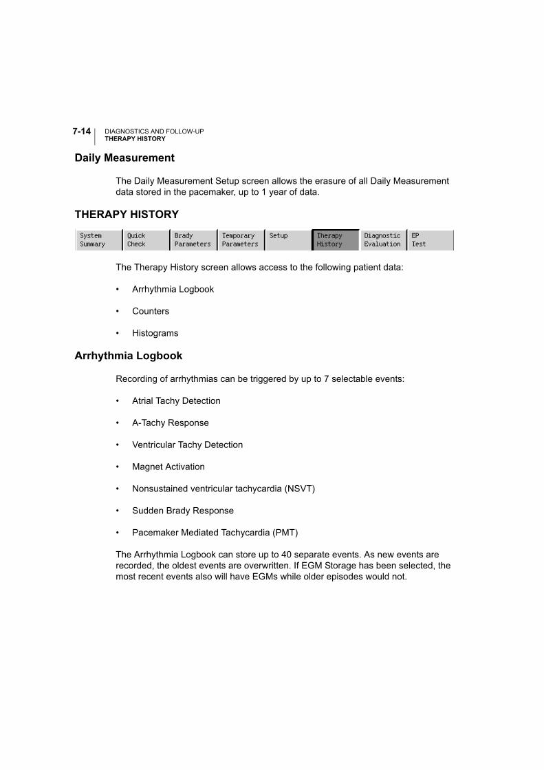
DIAGNOSTICS AND FOLLOW-UPTHERAPY HISTORY
7-14
Daily Measurement
The Daily Measurement Setup screen allows the erasure of all Daily Measurement data stored in the pacemaker, up to 1 year of data.
THERAPY HISTORY
The Therapy History screen allows access to the following patient data:
• Arrhythmia Logbook
• Counters
• Histograms
Arrhythmia Logbook
Recording of arrhythmias can be triggered by up to 7 selectable events:
• Atrial Tachy Detection
• A-Tachy Response
• Ventricular Tachy Detection
• Magnet Activation
• Nonsustained ventricular tachycardia (NSVT)
• Sudden Brady Response
• Pacemaker Mediated Tachycardia (PMT)
The Arrhythmia Logbook can store up to 40 separate events. As new events are recorded, the oldest events are overwritten. If EGM Storage has been selected, the most recent events also will have EGMs while older episodes would not.
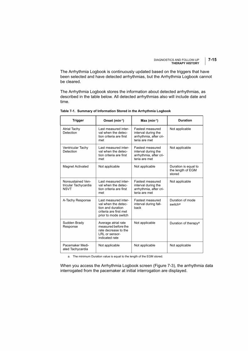
DIAGNOSTICS AND FOLLOW-UPTHERAPY HISTORY
7-15
The Arrhythmia Logbook is continuously updated based on the triggers that have been selected and have detected arrhythmias, but the Arrhythmia Logbook cannot be cleared.
The Arrhythmia Logbook stores the information about detected arrhythmias, as described in the table below. All detected arrhythmias also will include date and time.
When you access the Arrhythmia Logbook screen (Figure 7-3), the arrhythmia data interrogated from the pacemaker at initial interrogation are displayed.
Table 7-1. Summary of Information Stored in the Arrhythmia Logbook
Trigger Onset (min-¹) Max (min-¹) Duration
Atrial Tachy Detection
Last measured inter-val when the detec-tion criteria are first met
Fastest measured interval during the arrhythmia, after cri-teria are met
Not applicable
Ventricular Tachy Detection
Last measured inter-val when the detec-tion criteria are first met
Fastest measured interval during the arrhythmia, after cri-teria are met
Not applicable
Magnet Activated Not applicable Not applicable Duration is equal to the length of EGM stored
Nonsustained Ven-tricular Tachycardia NSVT
Last measured inter-val when the detec-tion criteria are first met
Fastest measured interval during the arrhythmia, after cri-teria are met
Not applicable
A-Tachy Response Last measured inter-val when the detec-tion and duration criteria are first met prior to mode switch
Fastest measuredinterval during fall-back
Duration of mode switcha
a. The minimum Duration value is equal to the length of the EGM stored.
Sudden Brady Response
Average atrial rate measured before the rate decrease to the LRL or sensor-indicated rate
Not applicable Duration of therapya
Pacemaker Medi-ated Tachycardia
Not applicable Not applicable Not applicable
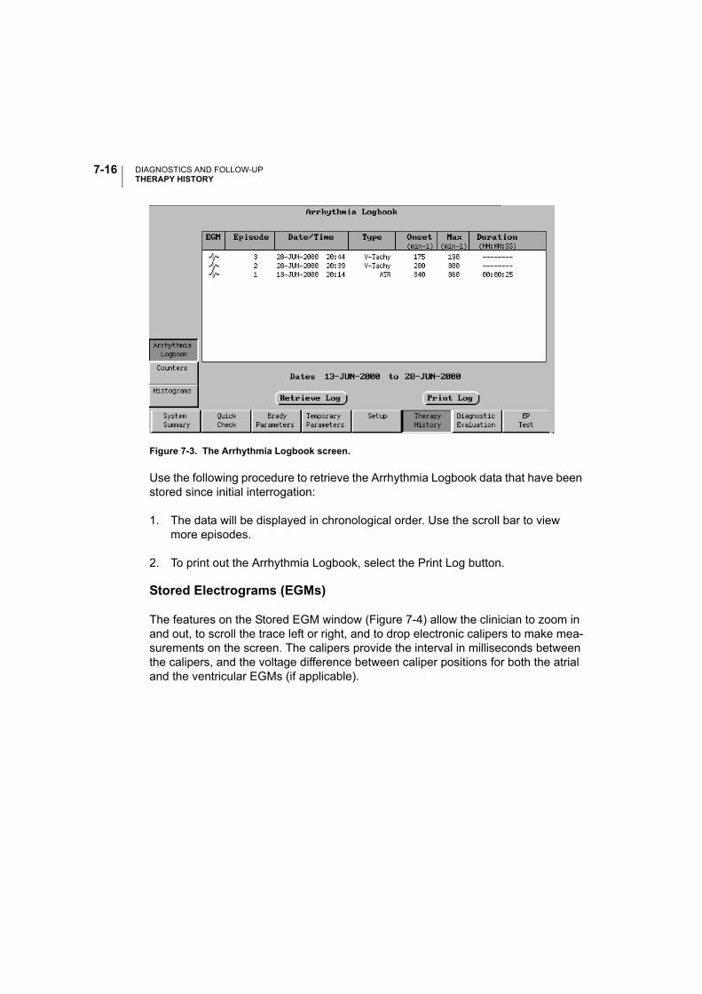
DIAGNOSTICS AND FOLLOW-UPTHERAPY HISTORY
7-16
Figure 7-3. The Arrhythmia Logbook screen.
Use the following procedure to retrieve the Arrhythmia Logbook data that have been stored since initial interrogation:
1. The data will be displayed in chronological order. Use the scroll bar to view more episodes.
2. To print out the Arrhythmia Logbook, select the Print Log button.
Stored Electrograms (EGMs)
The features on the Stored EGM window (Figure 7-4) allow the clinician to zoom in and out, to scroll the trace left or right, and to drop electronic calipers to make mea-surements on the screen. The calipers provide the interval in milliseconds between the calipers, and the voltage difference between caliper positions for both the atrial and the ventricular EGMs (if applicable).
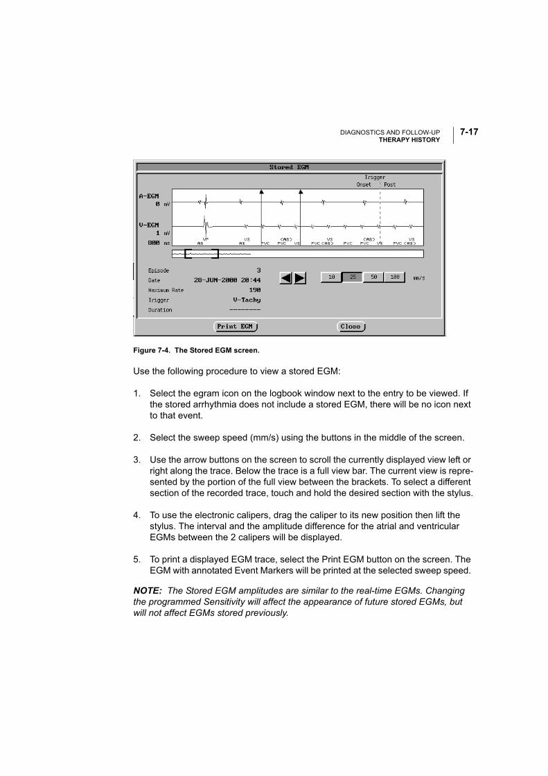
DIAGNOSTICS AND FOLLOW-UPTHERAPY HISTORY
7-17
Figure 7-4. The Stored EGM screen.
Use the following procedure to view a stored EGM:
1. Select the egram icon on the logbook window next to the entry to be viewed. If the stored arrhythmia does not include a stored EGM, there will be no icon next to that event.
2. Select the sweep speed (mm/s) using the buttons in the middle of the screen.
3. Use the arrow buttons on the screen to scroll the currently displayed view left or right along the trace. Below the trace is a full view bar. The current view is repre-sented by the portion of the full view between the brackets. To select a different section of the recorded trace, touch and hold the desired section with the stylus.
4. To use the electronic calipers, drag the caliper to its new position then lift the stylus. The interval and the amplitude difference for the atrial and ventricular EGMs between the 2 calipers will be displayed.
5. To print a displayed EGM trace, select the Print EGM button on the screen. The EGM with annotated Event Markers will be printed at the selected sweep speed.
NOTE: The Stored EGM amplitudes are similar to the real-time EGMs. Changing the programmed Sensitivity will affect the appearance of future stored EGMs, but will not affect EGMs stored previously.

DIAGNOSTICS AND FOLLOW-UPTHERAPY HISTORY
7-18
Counters
Event Counters record the number of intrinsic and pacemaker-mediated events that occur during an event recording period. This period begins with the last time the Counters were reset by the clinician and ends when the data are retrieved from the pacemaker via telemetry. Neither data retrieval nor changing the programmed parameters resets the Counters.
The following events are counted and recorded when relevant to the currently pro-grammed permanent pacing mode:
• Paced and Sensed Events
• A-Tachy Response Mode Switch Data
• Total ATR Mode Switches
• Total ATR Mode Switch Time
• Maximum Mode Switch Time
• Average Mode Switch Time
• Ectopic Beats
• PACs
• Single or Double PVCs
• Three or More PVCs
• Atrial Tachy Detection
• Ventricular Tachy Detection
• Rate Hysteresis searches—total number and number of successful searches
• Wenckebach Events (PMT Termination algorithm must be active for this coun-ter)
The event counters can be reset via telemetry by selecting the Reset Histograms/Counters button on the Counters screen (Figure 7-5). Use caution when performing
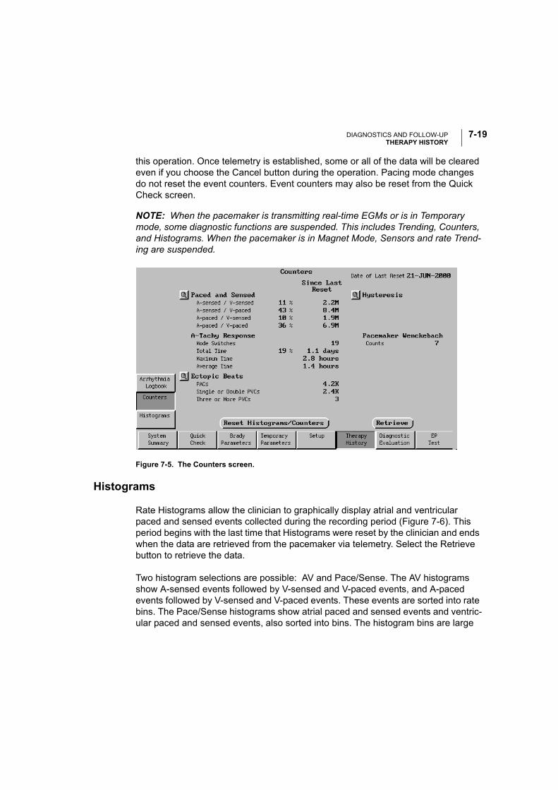
DIAGNOSTICS AND FOLLOW-UPTHERAPY HISTORY
7-19
this operation. Once telemetry is established, some or all of the data will be cleared even if you choose the Cancel button during the operation. Pacing mode changes do not reset the event counters. Event counters may also be reset from the Quick Check screen.
NOTE: When the pacemaker is transmitting real-time EGMs or is in Temporary mode, some diagnostic functions are suspended. This includes Trending, Counters, and Histograms. When the pacemaker is in Magnet Mode, Sensors and rate Trend-ing are suspended.
Figure 7-5. The Counters screen.
Histograms
Rate Histograms allow the clinician to graphically display atrial and ventricular paced and sensed events collected during the recording period (Figure 7-6). This period begins with the last time that Histograms were reset by the clinician and ends when the data are retrieved from the pacemaker via telemetry. Select the Retrieve button to retrieve the data.
Two histogram selections are possible: AV and Pace/Sense. The AV histograms show A-sensed events followed by V-sensed and V-paced events, and A-paced events followed by V-sensed and V-paced events. These events are sorted into rate bins. The Pace/Sense histograms show atrial paced and sensed events and ventric-ular paced and sensed events, also sorted into bins. The histogram bins are large
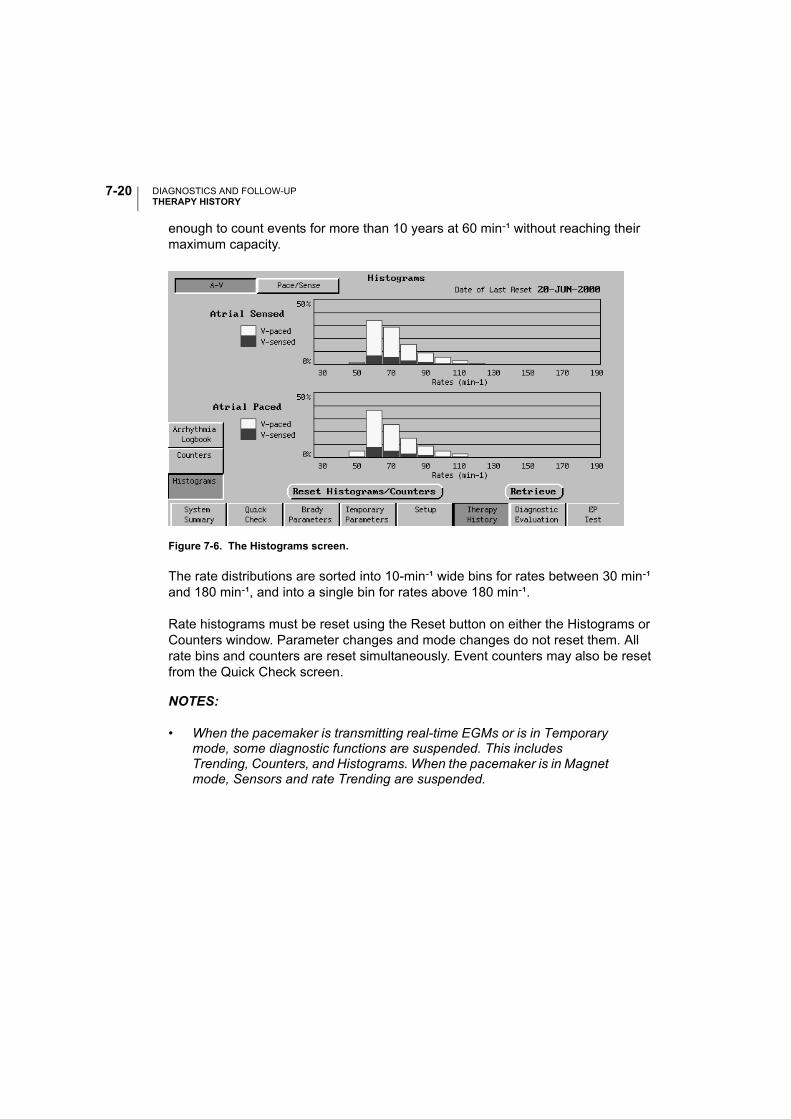
DIAGNOSTICS AND FOLLOW-UPTHERAPY HISTORY
7-20
enough to count events for more than 10 years at 60 min-¹ without reaching their maximum capacity.
Figure 7-6. The Histograms screen.
The rate distributions are sorted into 10-min-¹ wide bins for rates between 30 min-¹ and 180 min-¹, and into a single bin for rates above 180 min-¹.
Rate histograms must be reset using the Reset button on either the Histograms or Counters window. Parameter changes and mode changes do not reset them. All rate bins and counters are reset simultaneously. Event counters may also be reset from the Quick Check screen.
NOTES:
• When the pacemaker is transmitting real-time EGMs or is in Temporary mode, some diagnostic functions are suspended. This includes Trending, Counters, and Histograms. When the pacemaker is in Magnet mode, Sensors and rate Trending are suspended.
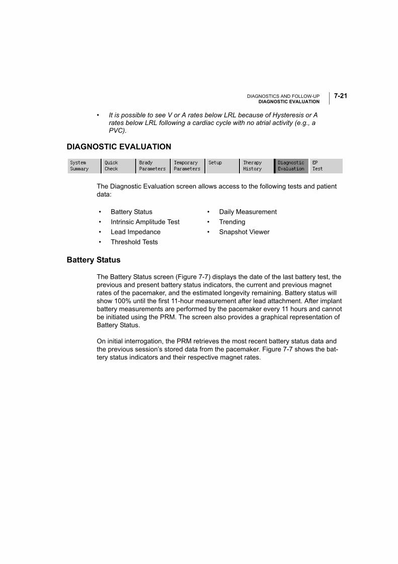
DIAGNOSTICS AND FOLLOW-UPDIAGNOSTIC EVALUATION
7-21
• It is possible to see V or A rates below LRL because of Hysteresis or A rates below LRL following a cardiac cycle with no atrial activity (e.g., a PVC).
DIAGNOSTIC EVALUATION
The Diagnostic Evaluation screen allows access to the following tests and patient data:
Battery Status
The Battery Status screen (Figure 7-7) displays the date of the last battery test, the previous and present battery status indicators, the current and previous magnet rates of the pacemaker, and the estimated longevity remaining. Battery status will show 100% until the first 11-hour measurement after lead attachment. After implant battery measurements are performed by the pacemaker every 11 hours and cannot be initiated using the PRM. The screen also provides a graphical representation of Battery Status.
On initial interrogation, the PRM retrieves the most recent battery status data and the previous session’s stored data from the pacemaker. Figure 7-7 shows the bat-tery status indicators and their respective magnet rates.
• Battery Status • Daily Measurement
• Intrinsic Amplitude Test • Trending
• Lead Impedance • Snapshot Viewer
• Threshold Tests
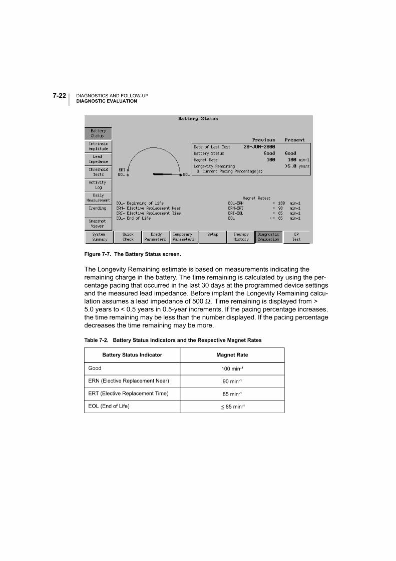
DIAGNOSTICS AND FOLLOW-UPDIAGNOSTIC EVALUATION
7-22
Figure 7-7. The Battery Status screen.
The Longevity Remaining estimate is based on measurements indicating the remaining charge in the battery. The time remaining is calculated by using the per-centage pacing that occurred in the last 30 days at the programmed device settings and the measured lead impedance. Before implant the Longevity Remaining calcu-lation assumes a lead impedance of 500 Ω. Time remaining is displayed from > 5.0 years to < 0.5 years in 0.5-year increments. If the pacing percentage increases, the time remaining may be less than the number displayed. If the pacing percentage decreases the time remaining may be more.
Table 7-2. Battery Status Indicators and the Respective Magnet Rates
Battery Status Indicator Magnet Rate
Good 100 min-¹
ERN (Elective Replacement Near) 90 min-¹
ERT (Elective Replacement Time) 85 min-¹
EOL (End of Life) < 85 min-¹
DIAGNOSTICS AND FOLLOW-UPDIAGNOSTIC EVALUATION
7-23
Intrinsic Amplitude Test
The Intrinsic Amplitude Test measures and displays the intrinsic amplitude for the atrium and/or ventricle. Intrinsic measurement will be available for a given cardiac chamber only if sensing is enabled for that chamber in the current pacing mode.
For intrinsic measurements in single-chamber modes, the clinician can temporarily program a lower LRL value to bring out the patient’s underlying rhythm. This param-eter change is in effect only during the test.
If the Intrinsic Amplitude Test is desired for both chambers, the atrial and the ventric-ular measurements must be conducted individually. In this case, the clinician can program the pacemaker to temporarily change the LRL and AV Delay for the dura-tion of the test. The results for each chamber will be gathered in separate but adja-cent search periods.
The Intrinsic Amplitude Test is based on the measurement of one complex per chamber. The test is complete and all effects of the parameters programmed for the test are terminated within 10 seconds for each chamber measured, or when either of the following occur:
• The test is terminated via a command from the PRM (e.g., selecting Cancel or pressing the STAT PACE key)
• The pacemaker exits the temporary state when the telemetry link is broken
The pacemaker stores the results of the last test so that the data from the previous session and the results of the current test can be viewed simultaneously.
Follow these steps to perform an Intrinsic Amplitude Test:
1. Select the Intrinsic Amplitude button on the Diagnostic Evaluation screen.
2. Select the LRL and AV Delay values that will allow the intrinsic rhythms to be seen.
3. Place the wand over the pacemaker, then select the Start button on the screen. The measurement requires a maximum of 10 seconds of telemetry time per chamber, depending on the presence of intrinsic activity. When the tests are completed, the data will be displayed in the Present column.

DIAGNOSTICS AND FOLLOW-UPDIAGNOSTIC EVALUATION
7-24
4. If the tests were unsuccessful because the programmed LRL and/or AV Delay did not allow intrinsic rhythms to be seen (i.e., the Measured Amplitude field reports Paced), repeat steps 2 and 3. If the tests are unsuccessful, an NR message on a popup window will indicate that the measurements could not be completed.
NOTE: Parameters changed on the Intrinsic Tests screen also will be in effect dur-ing Quick Check.
A report of the displayed test results can be printed as directed in “Obtaining a Printed Report” on page 8-9.
Lead Impedance Test
The Lead Impedance Test will report the lead Impedance, pacing Amplitude, Pulse Width, Current, and Energy at permanently programmed output settings for the leads in the pacemaker system. These energy calculations reflect energy used at programmed settings. To facilitate the measurement, the Amplitude and Pulse Width parameters are temporarily changed to predetermined values based on per-manently programmed settings, and the pacemaker switches to a triggered mode. Once the measurements are completed or the measurement period has expired, the permanently programmed pacing parameters are restored.
If the currently programmed pacing Amplitude is 3.5 V or less for the duration of the test, the Amplitude will be set at 3.5 V. If the Amplitude is 4.0, 4.5, or 5.0 V, the Amplitude will be set at 5.0 V. If the Amplitude is 6.5 V, the amplitude will remain at 6.5 V.
If the currently programmed Pulse Width is less than 0.4 ms, the Pulse Width will be set to 0.4 ms; otherwise, the Pulse Width for the test will be set to the currently pro-grammed Pulse Width.
The impedances for the test are based on the measurement of one event and will be reported as <100 Ω, 100 Ω to 2500 Ω in increments of 10 Ω, and >2500 Ω.
If an interactive lead impedance measurement is conducted in DDD mode, the lead impedance for each chamber will be measured separately but in adjacent search periods.
The Lead Impedance Test is complete and the original parameters are restored within 10 seconds for each chamber measured, or sooner if the test is terminated via the Cancel button, or by breaking the telemetry link.
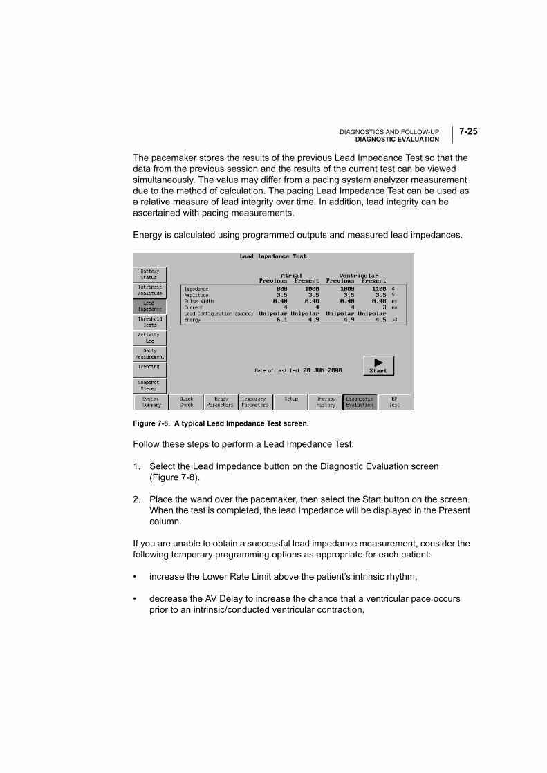
DIAGNOSTICS AND FOLLOW-UPDIAGNOSTIC EVALUATION
7-25
The pacemaker stores the results of the previous Lead Impedance Test so that the data from the previous session and the results of the current test can be viewed simultaneously. The value may differ from a pacing system analyzer measurement due to the method of calculation. The pacing Lead Impedance Test can be used as a relative measure of lead integrity over time. In addition, lead integrity can be ascertained with pacing measurements.
Energy is calculated using programmed outputs and measured lead impedances.
Figure 7-8. A typical Lead Impedance Test screen.
Follow these steps to perform a Lead Impedance Test:
1. Select the Lead Impedance button on the Diagnostic Evaluation screen (Figure 7-8).
2. Place the wand over the pacemaker, then select the Start button on the screen. When the test is completed, the lead Impedance will be displayed in the Present column.
If you are unable to obtain a successful lead impedance measurement, consider the following temporary programming options as appropriate for each patient:
• increase the Lower Rate Limit above the patient’s intrinsic rhythm,
• decrease the AV Delay to increase the chance that a ventricular pace occurs prior to an intrinsic/conducted ventricular contraction,
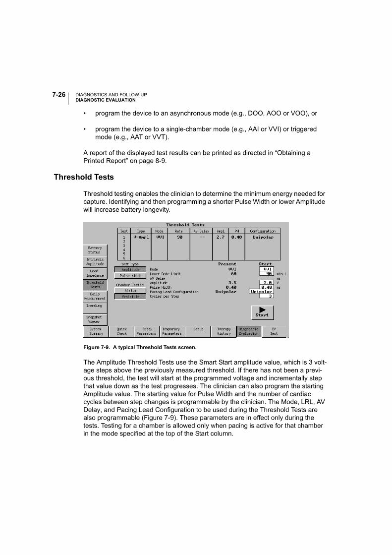
DIAGNOSTICS AND FOLLOW-UPDIAGNOSTIC EVALUATION
7-26
• program the device to an asynchronous mode (e.g., DOO, AOO or VOO), or
• program the device to a single-chamber mode (e.g., AAI or VVI) or triggered mode (e.g., AAT or VVT).
A report of the displayed test results can be printed as directed in “Obtaining a Printed Report” on page 8-9.
Threshold Tests
Threshold testing enables the clinician to determine the minimum energy needed for capture. Identifying and then programming a shorter Pulse Width or lower Amplitude will increase battery longevity.
Figure 7-9. A typical Threshold Tests screen.
The Amplitude Threshold Tests use the Smart Start amplitude value, which is 3 volt-age steps above the previously measured threshold. If there has not been a previ-ous threshold, the test will start at the programmed voltage and incrementally step that value down as the test progresses. The clinician can also program the starting Amplitude value. The starting value for Pulse Width and the number of cardiac cycles between step changes is programmable by the clinician. The Mode, LRL, AV Delay, and Pacing Lead Configuration to be used during the Threshold Tests are also programmable (Figure 7-9). These parameters are in effect only during the tests. Testing for a chamber is allowed only when pacing is active for that chamber in the mode specified at the top of the Start column.
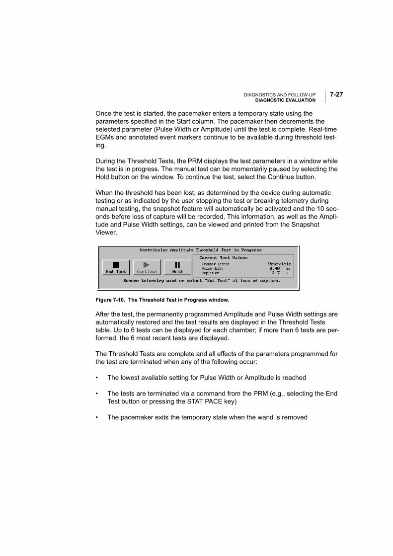
DIAGNOSTICS AND FOLLOW-UPDIAGNOSTIC EVALUATION
7-27
Once the test is started, the pacemaker enters a temporary state using the parameters specified in the Start column. The pacemaker then decrements the selected parameter (Pulse Width or Amplitude) until the test is complete. Real-time EGMs and annotated event markers continue to be available during threshold test-ing.
During the Threshold Tests, the PRM displays the test parameters in a window while the test is in progress. The manual test can be momentarily paused by selecting the Hold button on the window. To continue the test, select the Continue button.
When the threshold has been lost, as determined by the device during automatic testing or as indicated by the user stopping the test or breaking telemetry during manual testing, the snapshot feature will automatically be activated and the 10 sec-onds before loss of capture will be recorded. This information, as well as the Ampli-tude and Pulse Width settings, can be viewed and printed from the Snapshot Viewer.
After the test, the permanently programmed Amplitude and Pulse Width settings are automatically restored and the test results are displayed in the Threshold Tests table. Up to 6 tests can be displayed for each chamber; if more than 6 tests are per-formed, the 6 most recent tests are displayed.
The Threshold Tests are complete and all effects of the parameters programmed for the test are terminated when any of the following occur:
• The lowest available setting for Pulse Width or Amplitude is reached
• The tests are terminated via a command from the PRM (e.g., selecting the End Test button or pressing the STAT PACE key)
• The pacemaker exits the temporary state when the wand is removed
Figure 7-10. The Threshold Test in Progress window.

DIAGNOSTICS AND FOLLOW-UPDIAGNOSTIC EVALUATION
7-28
Using the Automatic Threshold Testing Functions
Follow these steps to perform Threshold Tests:
1. Select the Threshold Tests button on the Diagnostic Evaluation screen.
2. Select the type of test to be performed. Two options are available:
• Choose Amplitude to decrement the pulse amplitude during the test or
• Choose Pulse Width to decrement the pulse width during the test
3. For dual-chamber modes, select Atrium to test the atrial thresholds or Ventricle to test the ventricular thresholds.
4. Enter the starting values for each applicable parameter in the Start column. Parameter applicability is dependent on the Mode selected.
5. Select the Start button on the screen to begin the threshold test. After the pro-grammed number of cycles, the pacemaker automatically decrements the Amplitude or Pulse Width. This will continue until the telemetry link is broken, End Test or STAT PACE is selected, or until the lowest value has been tested.
6. Watch the ECG monitor and break telemetry by removing the wand or selecting the End Test button when loss of capture is observed. The measurement dis-played is one step higher than the step at which the test was terminated.
At the end of the test, the previously programmed permanent values are imme-diately restored.
7. To perform another threshold test, make changes to the test parameter values in the Change column if desired, then begin again with step 5. Results of the tests will be displayed on the screen table. If more than 6 tests are performed, the last 6 tests are displayed by chamber tested, with the most recent test at the top.
NOTE: Parameters changed on the Threshold Tests screen also will be in effect during Quick Check.
A report of the displayed test results can be printed as directed in “Obtaining a Printed Report” on page 8-9.

DIAGNOSTICS AND FOLLOW-UPDIAGNOSTIC EVALUATION
7-29
Daily Measurement
Intrinsic Amplitude Measurement
Once each day, based on a 21-hour clock the pacemaker will automatically attempt to measure intrinsic P- and R-wave amplitudes for each cardiac chamber in which sensing is enabled. This measurement will not affect normal pacemaker therapy. The measurement will be taken during a 256-cardiac cycle period. When the pace-maker is operating in a dual-chamber mode, the atrial and the ventricular measure-ments will be conducted individually. The Intrinsic Amplitude Measurement for each chamber will be gathered in separate but adjacent search periods.
Daily amplitude measurements will be stored for 7 days. After 7 days, the pace-maker calculates and stores a weekly minimum measurement. These measure-ments are stored for 52 weeks. At a given time, you can access the daily measurements for the last 7 days, and the weekly measurements for the last 52 weeks.
The daily amplitude measurement cannot be taken if events during the test period were all paced. If the measurement is unsuccessful and the measurement period has not expired, the pacemaker will attempt the measurement again. If the test period expires before the measurement can be completed, no data will be stored for that day. Data for other days are not affected.
Lead Impedance Measurement
Once each day, based on a 21-hour clock, the pacemaker will automatically attempt to measure the pacemaker system Lead Impedance for each cardiac chamber in which pacing is enabled. To facilitate the measurement, the Amplitude and Pulse Width parameters are temporarily changed to predetermined values. Once the measurement is completed, the permanently programmed pacing parameters are restored.
If the currently programmed Pulse Width is less than 0.4 ms, the Pulse Width will be set to 0.4 ms; otherwise, the Pulse Width for the test will be set to the currently pro-grammed Pulse Width.
If the currently programmed pacing Amplitude is 3.5 V or less, the Amplitude will be set at 3.5 V. If the pacing Amplitude is 4.0, 4.5, or 5.0 V, the Amplitude is set to 5.0 V. If the Amplitude is set to 6.5 V, it remains at 6.5 V.
DIAGNOSTICS AND FOLLOW-UPDIAGNOSTIC EVALUATION
7-30
Once the measurement is initiated, the pacemaker will allow the system to reach the voltage described above. Once this voltage is reached, the measurement will be taken. If the chamber being tested is having sensed events, the pacing output will be delivered by triggered mode. Triggered pacing will not be delivered during a PVC, a refractory event or when the patient’s intrinsic rhythm is faster than the Maximum Tracking Rate. When the pacemaker is operating in a dual-chamber mode, the atrial and the ventricular measurements will be conducted individually. The Lead Impedance for each chamber will be gathered in separate but adjacent search periods.
Daily impedance measurements will be stored for 7 days. After 7 days, the pace-maker calculates and stores a weekly average measurement. These measurements are stored for 52 weeks. At a given time, you can access the daily measurements for the last 7 days, and the weekly average measurements for the last 52 weeks.
Lead tests may not be conducted in the atrium and/or ventricle if the patient's intrinsic rate is faster than the Maximum Tracking Rate (e.g., devices will not pace beyond this rate). Additionally, lead tests may not be conducted in the atrium for the following reasons:
• In DDD(R) mode, if the pacemaker has ATR mode switched to a non-atrial pac-ing mode (e.g., VDI) due to an atrial arrhythmia, pacing will not be delivered.
• If the Atrial Flutter Response feature is programmed ON and is active during an atrial flutter.
Displaying Daily Measurement Data
The Daily Measurement screens allow the clinician to display the daily measure-ment data stored in the pacemaker in a tabular or a graphical format.
The graphical screen (Figure 7-11) displays the stored data in 2 views: a point-plot graph showing the weekly measurements and a point-plot graph showing the daily measurements for the last 7 days.
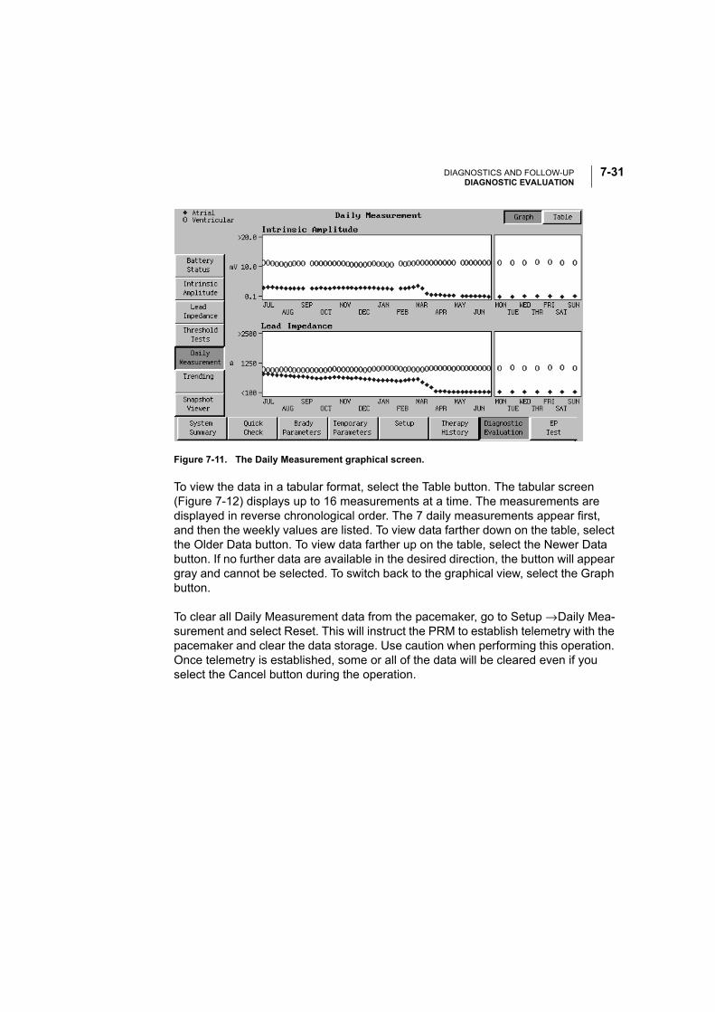
DIAGNOSTICS AND FOLLOW-UPDIAGNOSTIC EVALUATION
7-31
Figure 7-11. The Daily Measurement graphical screen.
To view the data in a tabular format, select the Table button. The tabular screen (Figure 7-12) displays up to 16 measurements at a time. The measurements are displayed in reverse chronological order. The 7 daily measurements appear first, and then the weekly values are listed. To view data farther down on the table, select the Older Data button. To view data farther up on the table, select the Newer Data button. If no further data are available in the desired direction, the button will appear gray and cannot be selected. To switch back to the graphical view, select the Graph button.
To clear all Daily Measurement data from the pacemaker, go to Setup → Daily Mea-surement and select Reset. This will instruct the PRM to establish telemetry with the pacemaker and clear the data storage. Use caution when performing this operation. Once telemetry is established, some or all of the data will be cleared even if you select the Cancel button during the operation.
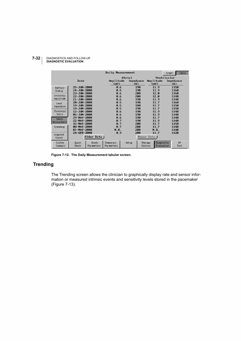
DIAGNOSTICS AND FOLLOW-UPDIAGNOSTIC EVALUATION
7-32
Figure 7-12. The Daily Measurement tabular screen.
Trending
The Trending screen allows the clinician to graphically display rate and sensor infor-mation or measured intrinsic events and sensitivity levels stored in the pacemaker (Figure 7-13).
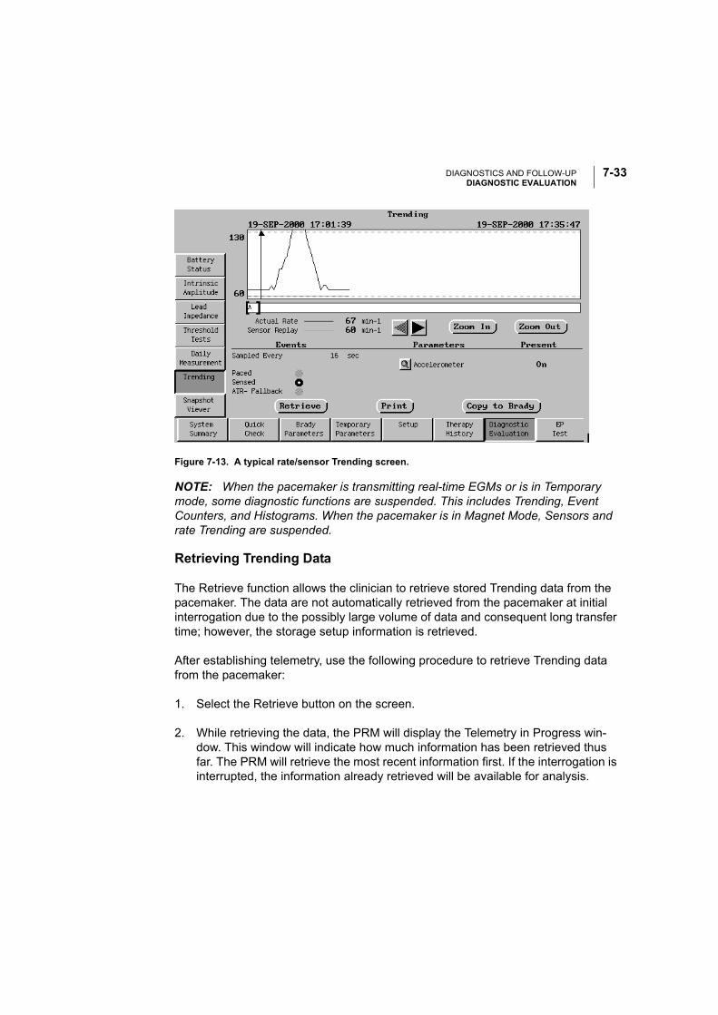
DIAGNOSTICS AND FOLLOW-UPDIAGNOSTIC EVALUATION
7-33
Figure 7-13. A typical rate/sensor Trending screen.
NOTE: When the pacemaker is transmitting real-time EGMs or is in Temporary mode, some diagnostic functions are suspended. This includes Trending, Event Counters, and Histograms. When the pacemaker is in Magnet Mode, Sensors and rate Trending are suspended.
Retrieving Trending Data
The Retrieve function allows the clinician to retrieve stored Trending data from the pacemaker. The data are not automatically retrieved from the pacemaker at initial interrogation due to the possibly large volume of data and consequent long transfer time; however, the storage setup information is retrieved.
After establishing telemetry, use the following procedure to retrieve Trending data from the pacemaker:
1. Select the Retrieve button on the screen.
2. While retrieving the data, the PRM will display the Telemetry in Progress win-dow. This window will indicate how much information has been retrieved thus far. The PRM will retrieve the most recent information first. If the interrogation is interrupted, the information already retrieved will be available for analysis.

DIAGNOSTICS AND FOLLOW-UPDIAGNOSTIC EVALUATION
7-34
Working with Rate/Sensor Trending Data
The PRM displays a graphical representation of the retrieved data. Replay allows the clinician to see how changes in the pacing parameters will affect the sensor response. Replay parameters cannot be modified until the trending data have been retrieved from the pacemaker. Parameter availability is dependent on the mode and the permanently programmed sensor.
Follow these steps to use the Trending Replay Parameters function:
1. Retrieve the trending data from the pacemaker using the procedure above. The PRM displays a graphical representation of the patient’s rate (black) and sensor response (orange) during the recording.
2. Select the magnifying glass icon next to the sensor (Accelerometer) button, then make changes to the Trending Replay Parameters to optimize the sensor response.
As the Trending Replay Parameters are modified, the application will modify the sensor graph to illustrate the effects that would result from the changes.
3. If the replayed parameters result in the optimal response, copy the changes to the Brady Parameters screen by selecting the Copy to Brady button.
NOTE: The Trending function records actual Accelerometer outputs during the sampling period. However, as these samples occur less frequently than in the actual device, some differences may be observed in the patient’s rate and the sensor response.
Working with Beat-to-Beat Rate Data
Retrieve the Beat-to-Beat data from the pacemaker using the procedure above.
Upon retrieval, the PRM will display the ventricular rate trend for the duration of the Beat-to-Beat recording. Sensor replay is not available.
By zooming into the level of greatest resolution, you can position the caliper on an individual cycle by dragging it with the stylus or selecting the arrow buttons. The fol-lowing information is then displayed for that cycle:
• V–V interval
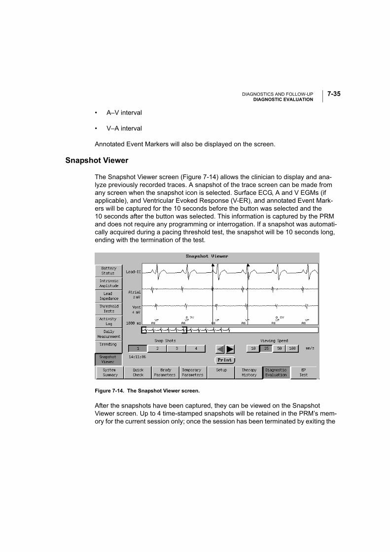
DIAGNOSTICS AND FOLLOW-UPDIAGNOSTIC EVALUATION
7-35
• A–V interval
• V–A interval
Annotated Event Markers will also be displayed on the screen.
Snapshot Viewer
The Snapshot Viewer screen (Figure 7-14) allows the clinician to display and ana-lyze previously recorded traces. A snapshot of the trace screen can be made from any screen when the snapshot icon is selected. Surface ECG, A and V EGMs (if applicable), and Ventricular Evoked Response (V-ER), and annotated Event Mark-ers will be captured for the 10 seconds before the button was selected and the 10 seconds after the button was selected. This information is captured by the PRM and does not require any programming or interrogation. If a snapshot was automati-cally acquired during a pacing threshold test, the snapshot will be 10 seconds long, ending with the termination of the test.
Figure 7-14. The Snapshot Viewer screen.
After the snapshots have been captured, they can be viewed on the Snapshot Viewer screen. Up to 4 time-stamped snapshots will be retained in the PRM’s mem-ory for the current session only; once the session has been terminated by exiting the
2
4

DIAGNOSTICS AND FOLLOW-UPEP TEST
7-36
Model 2892 software application or by interrogating a new patient, the data will be lost.
The features on the screen allow the clinician to zoom in and out, to scroll the trace left or right, and to make interval and amplitude measurements on the screen using electronic calipers. The interval and the amplitude difference between the two cali-pers will be displayed.
NOTE: At the 10-mm/sec speed, the annotated Event Markers will not be dis-played.
Use the following procedure to view and analyze a previously recorded snapshot:
1. Select the Snapshot Viewer toolbox button on the screen.
2. Select 1 of the 4 time-stamped buttons in the lower left of the Snapshot Viewer screen that identifies the snapshot you want to view.
3. Select the sweep speed using the buttons to the right of the snapshot selection buttons to change the view of the snapshot display.
4. Use the arrow buttons on the screen to scroll the currently displayed view left or right. Below the trace is a full view window of the 20-second snapshot. The brackets on the full-view window indicate which portion of the snapshot is shown in detail. To select a different section of the detailed recorded trace, touch and hold the desired section with the stylus.
5. To use the electronic calipers, drag the caliper to its new position, then lift the stylus. The interval and the amplitude difference for the atrial and ventricular EGMs between the two calipers will be displayed.
To print a displayed snapshot, select the Print button on the screen. The currently viewed snapshot and measurements will be printed.
EP TEST
The EP Test (Figure 7-15) enables the clinician to induce and/or terminate tachyar-rhythmias noninvasively. These tests can be performed while running the real-time intracardiac ECG traces and markers.
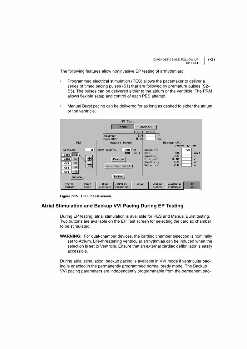
DIAGNOSTICS AND FOLLOW-UPEP TEST
7-37
The following features allow noninvasive EP testing of arrhythmias:
• Programmed electrical stimulation (PES) allows the pacemaker to deliver a series of timed pacing pulses (S1) that are followed by premature pulses (S2–S5). The pulses can be delivered either to the atrium or the ventricle. The PRM allows flexible setup and control of each PES attempt.
• Manual Burst pacing can be delivered for as long as desired to either the atrium or the ventricle.
Figure 7-15. The EP Test screen.
Atrial Stimulation and Backup VVI Pacing During EP Testing
During EP testing, atrial stimulation is available for PES and Manual Burst testing. Two buttons are available on the EP Test screen for selecting the cardiac chamber to be stimulated.
WARNING: For dual-chamber devices, the cardiac chamber selection is nominally set to Atrium. Life-threatening ventricular arrhythmias can be induced when the selection is set to Ventricle. Ensure that an external cardiac defibrillator is easily accessible.
During atrial stimulation, backup pacing is available in VVI mode if ventricular pac-ing is enabled in the permanently programmed normal brady mode. The Backup VVI pacing parameters are independently programmable from the permanent pac-
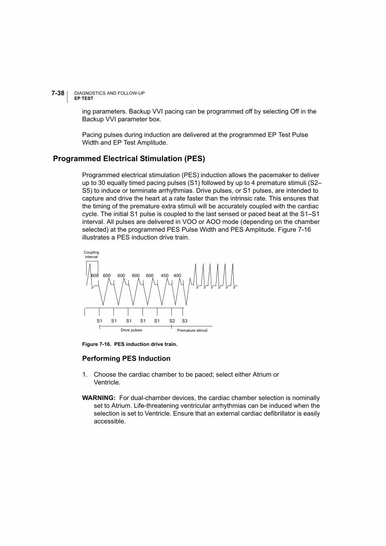
DIAGNOSTICS AND FOLLOW-UPEP TEST
7-38
ing parameters. Backup VVI pacing can be programmed off by selecting Off in the Backup VVI parameter box.
Pacing pulses during induction are delivered at the programmed EP Test Pulse Width and EP Test Amplitude.
Programmed Electrical Stimulation (PES)
Programmed electrical stimulation (PES) induction allows the pacemaker to deliver up to 30 equally timed pacing pulses (S1) followed by up to 4 premature stimuli (S2–S5) to induce or terminate arrhythmias. Drive pulses, or S1 pulses, are intended to capture and drive the heart at a rate faster than the intrinsic rate. This ensures that the timing of the premature extra stimuli will be accurately coupled with the cardiac cycle. The initial S1 pulse is coupled to the last sensed or paced beat at the S1–S1 interval. All pulses are delivered in VOO or AOO mode (depending on the chamber selected) at the programmed PES Pulse Width and PES Amplitude. Figure 7-16 illustrates a PES induction drive train.
Figure 7-16. PES induction drive train.
Performing PES Induction
1. Choose the cardiac chamber to be paced; select either Atrium orVentricle.
WARNING: For dual-chamber devices, the cardiac chamber selection is nominally set to Atrium. Life-threatening ventricular arrhythmias can be induced when the selection is set to Ventricle. Ensure that an external cardiac defibrillator is easily accessible.
S1 S1 S1 S1 S1 S2 S3
600 400600 600 600 600 450
Premature stimuli
Couplinginterval
Drive pulses

DIAGNOSTICS AND FOLLOW-UPEP TEST
7-39
2. To change the number of S1 pulses, select the box next to the words S1 Pulses, and select the desired value.
Two methods are available to change the cycle length of each pulse (pro-grammed in a range from 120–750 ms or Off):
a. Select a value box to the left of an S button to display a palette window, and select the desired value.
b. Select an S button to shift the arrow to that location, then select either the (+) or (–) buttons to increase or decrease the cycle length in 10-ms steps in the value box.
3. Select (do not hold) the Induce button to begin delivery of the drive train. The pointer will automatically move to the (–) button so the value can be decreased quickly, if desired, after the test is completed. When the programmed number of S1 pulses is delivered, the pacemaker will then deliver the programmed S2–S5 pulses. The pulses are delivered in sequence until a pulse is encountered that is set to Off (e.g., if S4 is Off and S5 is set to 200 ms, the S5 pulse will not be delivered).
Once induction is initiated, breaking the telemetry link will stop the PES delivery. If the Induce button is selected again while the S1 pulses are still being deliv-ered, the count of S1 pulses is restarted at the original number and the drive train is effectively extended.
4. PES induction is complete when the drive train and premature stimuli are delivered.
NOTE: Intracardiac EGMs and annotated Event Markers will continue to be dis-played during the entire test sequence.
Manual Burst Pacing
Manual Burst pacing pulses are delivered in VOO or AOO mode at the programmed EP Test Pulse Width and EP Test Amplitude.
Performing Manual Burst Pacing
1. Choose the cardiac chamber to be paced; select either Atrium or Ventricle.

DIAGNOSTICS AND FOLLOW-UPEP TEST
7-40
WARNING: For dual-chamber devices, the cardiac chamber selection is nominally set to Atrium. Life-threatening ventricular arrhythmias can be induced when the selection is set to Ventricle. Ensure that an external cardiac defibrillator is easily accessible.
2. Select the desired value for the Burst Interval; this indicates the cycle length of the intervals in the drive train and is programmable from 100–1000 ms.
3. Select the Enable button. The text on the Hold for Burst button will become selectable.
4. To deliver the burst, touch and hold the stylus on the Hold for Burst button. The Manual Burst will be delivered as long as the stylus is held on the button. Pulses will be at a constant rate.
NOTE: Intracardiac EGMs and annotated Event Markers will continue to be dis-played during the entire Manual Burst pacing.
5. To stop the burst delivery, lift the stylus from the screen. The text on the Hold for Burst button will become deselectable (gray) again.
6. To deliver additional Manual Burst pacing, repeat steps 3–5.

8-1
ELECTROGRAMS (EGMS) / EVENT MARKERS / REPORTS
CHAPTER 8
This chapter includes information about obtaining intracardiac electrograms (EGMs) and real-time annotated event markers, as well as printing reports of parameter set-tings, session activity, and diagnostics. The following procedures are described in this chapter:
• Displaying surface ECGs and EGMs on the PRM screen or an external recorder
• Displaying annotated Event Markers on the PRM screen
• Printing surface ECGs and EGMs from the PRM
• Printing surface ECGs and EGMs to an external recorder
• Obtaining printed reports of selected data from the programming session on either the internal or external printer
Refer to Appendix B, “External Cable Connections” for instructions on connecting the PRM and patient cables to an external recorder and connecting the PRM to an external printer.

ELECTROGRAMS (EGMS) / EVENT MARKERS / REPORTSVIEWING AND PRINTING REAL-TIME TRACES AND MARKERS
8-2
VIEWING AND PRINTING REAL-TIME TRACES AND MARKERS
In addition to displaying surface ECGs, the ALTRUA 20 systems can provide intra-cardiac EGMs and real-time annotated event markers that identify key intrinsic and pacemaker-related events. The annotated event markers can help you verify the effectiveness of selected parameter settings or simplify diagnosis of complex ECG rhythms.
• High-fidelity real-time atrial and ventricular EGMs and the ventricular evoked response EGM can be transmitted from the pacemaker to evaluate intracardiac signal morphology and rhythm and conduction disorders; they also facilitate the diagnosis of possible lead system issues such as lead fractures, insulation breaks, or dislodgments.
• Event markers can identify intrinsic cardiac and device-related events as interpreted by the pacemaker, and provide information such as sensed/paced events and therapy delivery. The event markers appear as abbreviated annotations on the PRM screen, and as full-disclosure annotations on the internal PRM printout.
• If Intervals are selected on the ECG menu, the key timing intervals will be dis-played on the internal PRM printout, but not on the PRM screen. The following intervals will be printed:
• AS (A–A Interval)
• AP (A–A Interval)
• VS (V–V Interval)
• VP (V–V Interval)
• VA (V–A Interval)
• AV (A–V Interval)
• REFR (PVARP)
NOTE: The full set of annotated event markers is not available when real-time EGMs are selected, but intervals or a subset of the markers are available. To use the full set of event markers, real-time EGMs must be deactivated. See Table 8-1 and Table 8-2 for a list of the event markers.

ELECTROGRAMS (EGMS) / EVENT MARKERS / REPORTSVIEWING AND PRINTING REAL-TIME TRACES AND MARKERS
8-3
Displaying Surface ECGs, EGMs, and Event Markers
The PRM can display three surface traces using six limb leads and one chest lead. The top displayed lead will be annotated with the pacing spike marker if that feature is selected. To display the pacing spike markers correctly, the Lead II electrodes must be connected to the patient, regardless of which lead is displayed. After select-ing the ECG icon on the PRM screen, use the following options to choose the dis-play (Figure 8-1):
• Select Leads —Use these value boxes to select whether surface trace, atrial EGMs, ventricular EGMs, or evoked response EGMs (V-ER) should be dis-played. The top value selection can only be a surface trace. These options are also available from any PRM screen.
• Trace Speed buttons—Select the desired trace speed button on the ECG dis-play: II (stop), > (play), and >> (fast forward).
• Show Markers—Select this check box to display markers.
• Printed Surface Gain—Adjust the surface gain of the traces that are captured on printouts by selecting the appropriate value.
• EGM Gain—Adjust the gain of the EGM trace by selecting the appropriate value (0.5x, 1x, or 2x).
• Surface Filter—Select the Filter On setting to minimize noise on the surface ECG. The Filter Off setting allows viewing surface ECGs with diagnostic filter settings.
• Pacing Spike Display—Program this feature On to show detected pacing spikes, annotated by a marker on the uppermost waveform.
• Printed Event Marker Annotation—Select Show Markers and Annotation to show the marker annotations (Table 8-1 and Table 8-2) on the printout. Select Show Markers and Intervals to show the intervals and a limited set of annotations.
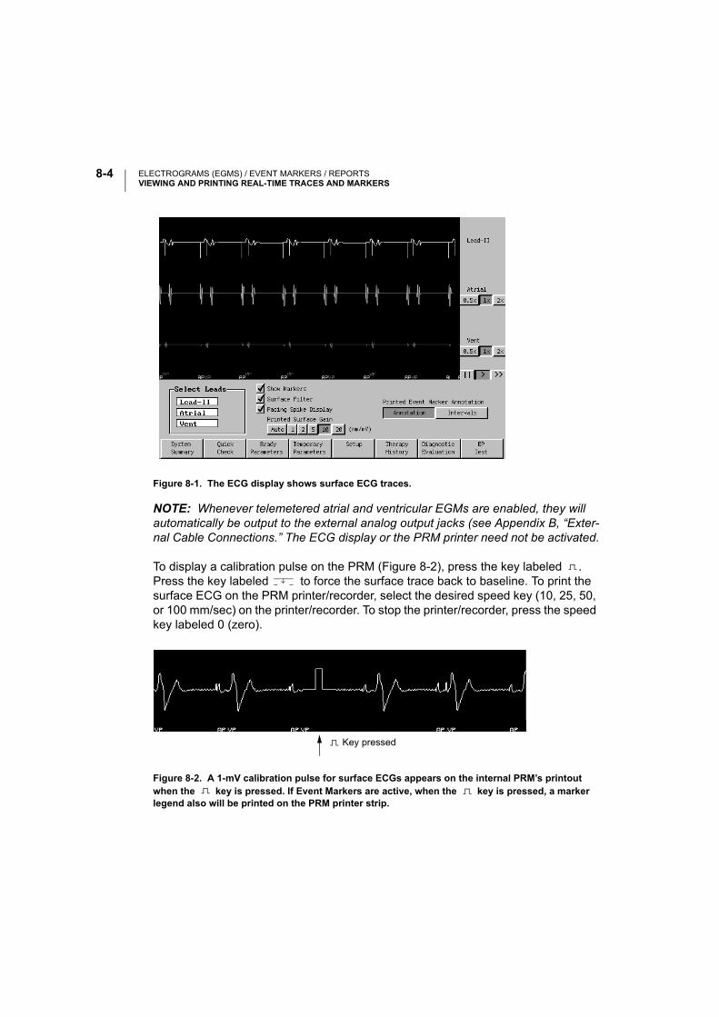
ELECTROGRAMS (EGMS) / EVENT MARKERS / REPORTSVIEWING AND PRINTING REAL-TIME TRACES AND MARKERS
8-4
Figure 8-1. The ECG display shows surface ECG traces.
NOTE: Whenever telemetered atrial and ventricular EGMs are enabled, they will automatically be output to the external analog output jacks (see Appendix B, “Exter-nal Cable Connections.” The ECG display or the PRM printer need not be activated.
To display a calibration pulse on the PRM (Figure 8-2), press the key labeled . Press the key labeled to force the surface trace back to baseline. To print the surface ECG on the PRM printer/recorder, select the desired speed key (10, 25, 50, or 100 mm/sec) on the printer/recorder. To stop the printer/recorder, press the speed key labeled 0 (zero).
Figure 8-2. A 1-mV calibration pulse for surface ECGs appears on the internal PRM’s printout when the key is pressed. If Event Markers are active, when the key is pressed, a marker legend also will be printed on the PRM printer strip.
Key pressed

ELECTROGRAMS (EGMS) / EVENT MARKERS / REPORTSVIEWING AND PRINTING REAL-TIME TRACES AND MARKERS
8-5
Printing to the Internal PRM Printer/Recorder
To print EGMs, the full set of annotated event markers, intervals, and the surface ECG on the PRM printer/recorder, select the desired speed key (10, 25, 50, or 100 mm/sec) on the printer/recorder while the traces are being displayed on the PRM screen.
NOTE: Event marker annotation definitions (Table 8-1 and Table 8-2) can also be printed by selecting the Marker Legend option on the Choose Reports to Print win-dow. Select the printer icon to open this window.
Press the key (calibrate) to print a list of the event marker annotations, if they are active (Figure 8-2).
To stop the printer/recorder, press the speed key labeled 0 (zero) on the printer/recorder.
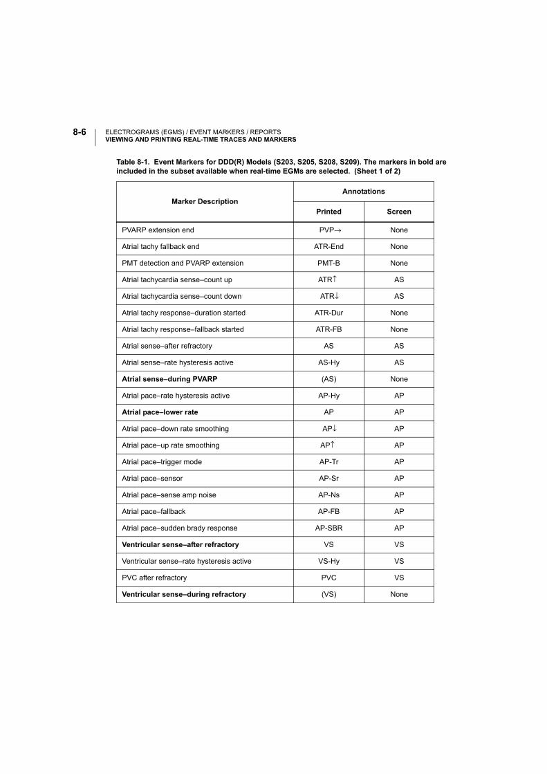
ELECTROGRAMS (EGMS) / EVENT MARKERS / REPORTSVIEWING AND PRINTING REAL-TIME TRACES AND MARKERS
8-6
Table 8-1. Event Markers for DDD(R) Models (S203, S205, S208, S209). The markers in bold are included in the subset available when real-time EGMs are selected. (Sheet 1 of 2)
Marker DescriptionAnnotations
Printed Screen
PVARP extension end PVP→ None
Atrial tachy fallback end ATR-End None
PMT detection and PVARP extension PMT-B None
Atrial tachycardia sense–count up ATR↑ AS
Atrial tachycardia sense–count down ATR↓ AS
Atrial tachy response–duration started ATR-Dur None
Atrial tachy response–fallback started ATR-FB None
Atrial sense–after refractory AS AS
Atrial sense–rate hysteresis active AS-Hy AS
Atrial sense–during PVARP (AS) None
Atrial pace–rate hysteresis active AP-Hy AP
Atrial pace–lower rate AP AP
Atrial pace–down rate smoothing AP↓ AP
Atrial pace–up rate smoothing AP↑ AP
Atrial pace–trigger mode AP-Tr AP
Atrial pace–sensor AP-Sr AP
Atrial pace–sense amp noise AP-Ns AP
Atrial pace–fallback AP-FB AP
Atrial pace–sudden brady response AP-SBR AP
Ventricular sense–after refractory VS VS
Ventricular sense–rate hysteresis active VS-Hy VS
PVC after refractory PVC VS
Ventricular sense–during refractory (VS) None
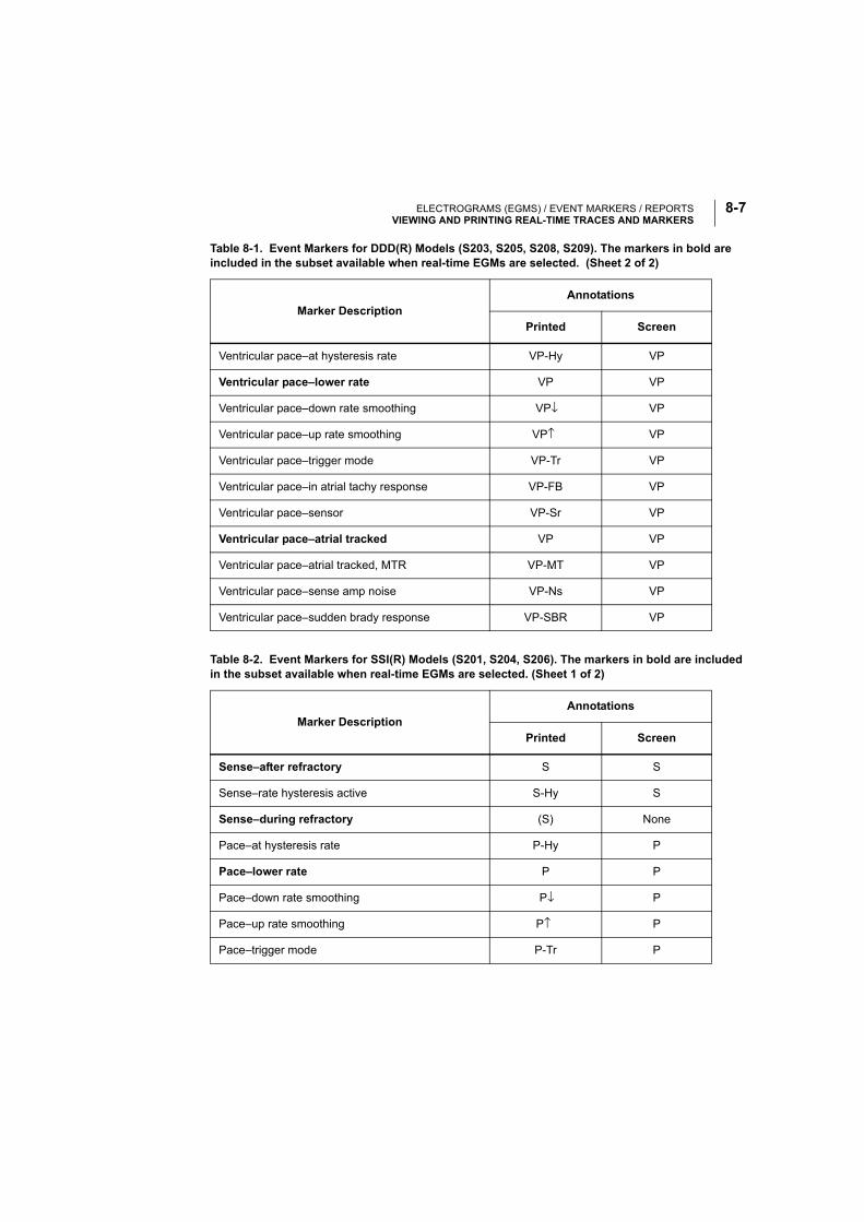
ELECTROGRAMS (EGMS) / EVENT MARKERS / REPORTSVIEWING AND PRINTING REAL-TIME TRACES AND MARKERS
8-7
Ventricular pace–at hysteresis rate VP-Hy VP
Ventricular pace–lower rate VP VP
Ventricular pace–down rate smoothing VP↓ VP
Ventricular pace–up rate smoothing VP↑ VP
Ventricular pace–trigger mode VP-Tr VP
Ventricular pace–in atrial tachy response VP-FB VP
Ventricular pace–sensor VP-Sr VP
Ventricular pace–atrial tracked VP VP
Ventricular pace–atrial tracked, MTR VP-MT VP
Ventricular pace–sense amp noise VP-Ns VP
Ventricular pace–sudden brady response VP-SBR VP
Table 8-2. Event Markers for SSI(R) Models (S201, S204, S206). The markers in bold are included in the subset available when real-time EGMs are selected. (Sheet 1 of 2)
Marker DescriptionAnnotations
Printed Screen
Sense–after refractory S S
Sense–rate hysteresis active S-Hy S
Sense–during refractory (S) None
Pace–at hysteresis rate P-Hy P
Pace–lower rate P P
Pace–down rate smoothing P↓ P
Pace–up rate smoothing P↑ P
Pace–trigger mode P-Tr P
Table 8-1. Event Markers for DDD(R) Models (S203, S205, S208, S209). The markers in bold are included in the subset available when real-time EGMs are selected. (Sheet 2 of 2)
Marker DescriptionAnnotations
Printed Screen

ELECTROGRAMS (EGMS) / EVENT MARKERS / REPORTSVIEWING AND PRINTING REAL-TIME TRACES AND MARKERS
8-8
Printing to an External Printer
The Model 3120 PRM with the Model 2892 CONSULT Software Application also supports printing reports on an external printer using 8.5 x 11-inch/A4 paper. Real-time ECGs and telemetered EGMs are not available on the external printer.
At the end of the initial device interrogation, the printer selection will default to Exter-nal if the external printer is connected and powered up. If the external printer was not connected or powered up at initial device interrogation but the clinician now wishes to use the external printer, perform the following steps:
1. Connect the external printer as shown in Appendix B, “External Cable Connections.”
2. Power up the printer.
3. Select the External printer on the Choose Reports to Print window. Select the printer icon to open this window. The clinician may use the external printer to print reports while simultaneously using the internal printer to print real-time ECGs and EGMs.
Printing to an External Recorder
To view intracardiac EGMs and the surface ECG on an external recorder, press the desired speed key on the external recorder while the traces are displayed on the PRM screen. See Appendix B, “External Cable Connections” for instructions on connecting the PRM to the external recorder. Refer to the manual for the external recorder for instructions specific to its operation.
Pace–sensor P-Sr P
Pace–sense amp noise P-Ns P
Table 8-2. Event Markers for SSI(R) Models (S201, S204, S206). The markers in bold are included in the subset available when real-time EGMs are selected. (Sheet 2 of 2)
Marker DescriptionAnnotations
Printed Screen
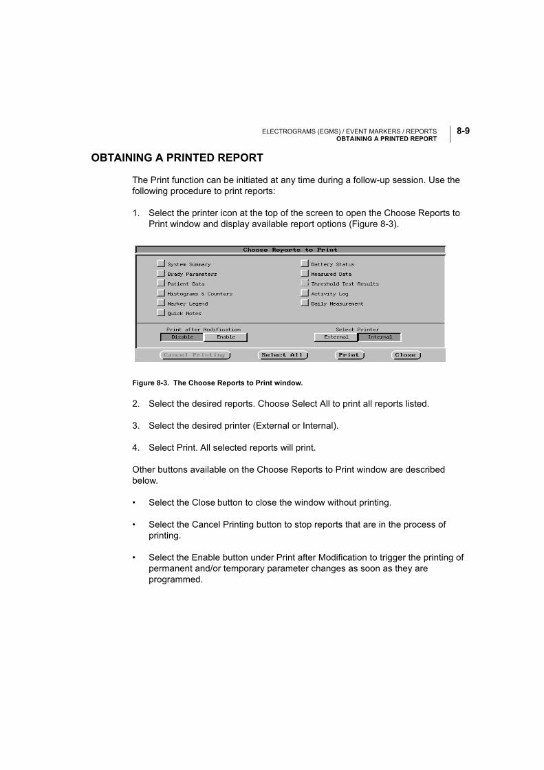
ELECTROGRAMS (EGMS) / EVENT MARKERS / REPORTSOBTAINING A PRINTED REPORT
8-9
OBTAINING A PRINTED REPORT
The Print function can be initiated at any time during a follow-up session. Use the following procedure to print reports:
1. Select the printer icon at the top of the screen to open the Choose Reports to Print window and display available report options (Figure 8-3).
Figure 8-3. The Choose Reports to Print window.
2. Select the desired reports. Choose Select All to print all reports listed.
3. Select the desired printer (External or Internal).
4. Select Print. All selected reports will print.
Other buttons available on the Choose Reports to Print window are described below.
• Select the Close button to close the window without printing.
• Select the Cancel Printing button to stop reports that are in the process of printing.
• Select the Enable button under Print after Modification to trigger the printing of permanent and/or temporary parameter changes as soon as they are programmed.

ELECTROGRAMS (EGMS) / EVENT MARKERS / REPORTSOBTAINING A PRINTED REPORT
8-10
NOTE: Be sure to print desired reports prior to selecting Quit or New Patient, since data are erased from the PRM’s memory when these actions are performed.
Printed reports, which are intended to be filed as part of the patient’s medical record, also identify the manufacturer, the institution name, the programming device, and the pacemaker name, model number, and serial number.

A-1
PACEMAKER MODES OF OPERATION
APPENDIX A
This appendix includes information about the programmable modes available with ALTRUA pacemakers. For an explanation of the codes used in pacing, see Table A-1.
PACEMAKER IDENTIFICATION CODES
The identification code of the North American Society of Pacing and Electrophysiol-ogy (NASPE) and the British Pacing and Electrophysiology Group (BPEG) is based on the following categories:
Positions I, II, and III identify the chamber paced, chamber sensed, and mode of response to conventional (P- and/or R-wave) sensing, respectively. The fourth posi-tion indicates rate modulation (adaptive-rate pacing). For an explanation of the other NASPE/BPEG codes, consult the article footnoted in Table A-1.
Table A-1. NASPE/BPEG Generic (NBG) Pacemaker Codea
a. Bernstein A, Camm AJ, Fletcher RD, et al: The NASPE/BPEG generic pacemaker code for anti-bradyarrhythmia and adaptive-rate pacing and antitachyarrhythmia devices. PACE 1987;10 (July):795.
Position I II III IV V
CategoryChambersPaced
ChambersSensed
Response to Sensing
Programmability, Rate Modulation
Antitachyarrhythmia Functions
Letters O–None
A–Atrium
V–Ventricle
D–Dual (A&V)
O–None
A–Atrium
V–Ventricle
D–Dual (A&V)
O–None
T–Triggered
I–Inhibited
D–Dual (T&I)
O–None
P–Simple Programmable
M–Multi-Programmable
C–Communicating
R–Rate Modulation
O–None
P–Pacing(Antitachyarrhythmia)
S–Shock
D–Dual (P&S)
MfgrsDesignationOnly
S–Single(A or V)
S–Single(A or V)
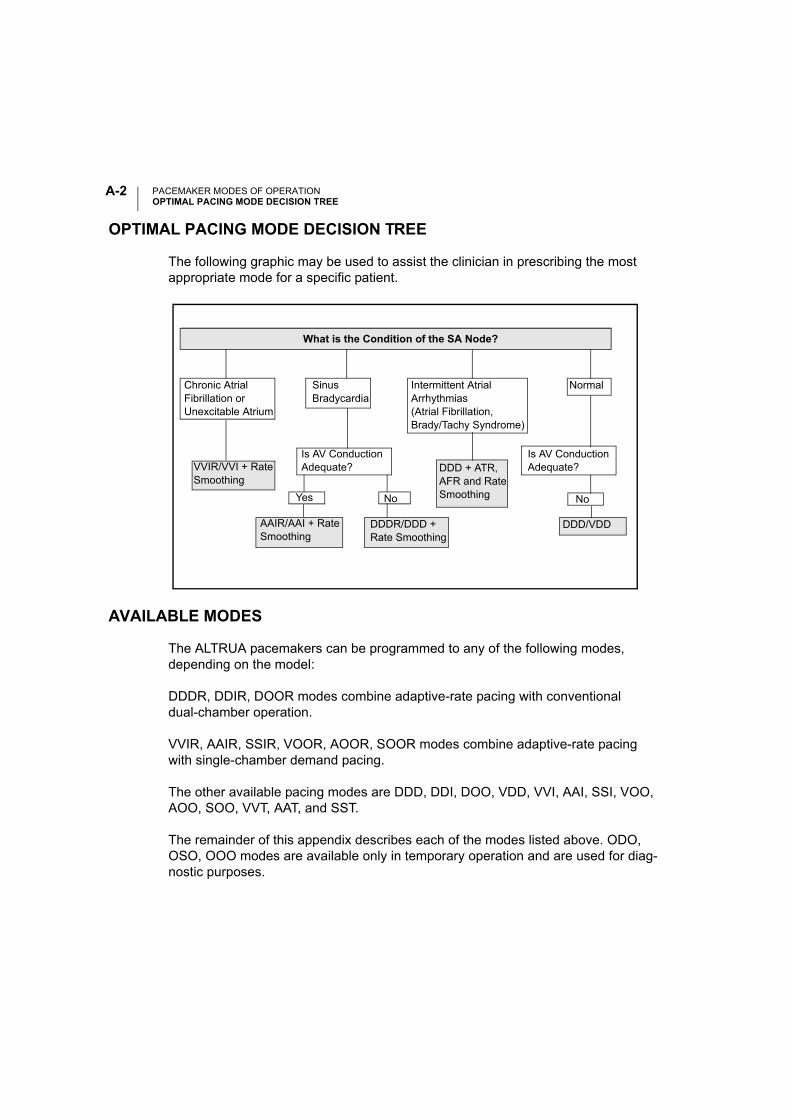
PACEMAKER MODES OF OPERATIONOPTIMAL PACING MODE DECISION TREE
A-2
OPTIMAL PACING MODE DECISION TREE
The following graphic may be used to assist the clinician in prescribing the most appropriate mode for a specific patient.
AVAILABLE MODES
The ALTRUA pacemakers can be programmed to any of the following modes, depending on the model:
DDDR, DDIR, DOOR modes combine adaptive-rate pacing with conventional dual-chamber operation.
VVIR, AAIR, SSIR, VOOR, AOOR, SOOR modes combine adaptive-rate pacing with single-chamber demand pacing.
The other available pacing modes are DDD, DDI, DOO, VDD, VVI, AAI, SSI, VOO, AOO, SOO, VVT, AAT, and SST.
The remainder of this appendix describes each of the modes listed above. ODO, OSO, OOO modes are available only in temporary operation and are used for diag-nostic purposes.
NoYes
Normal
Is AV ConductionAdequate? DDD + ATR,
AFR and RateSmoothing
DDD/VDDAAIR/AAI + Rate Smoothing
DDDR/DDD + Rate Smoothing
No
Is AV ConductionAdequate?
Intermittent AtrialArrhythmias (Atrial Fibrillation,Brady/Tachy Syndrome)
Chronic Atrial Fibrillation or Unexcitable Atrium
SinusBradycardia
VVIR/VVI + Rate Smoothing
What is the Condition of the SA Node?
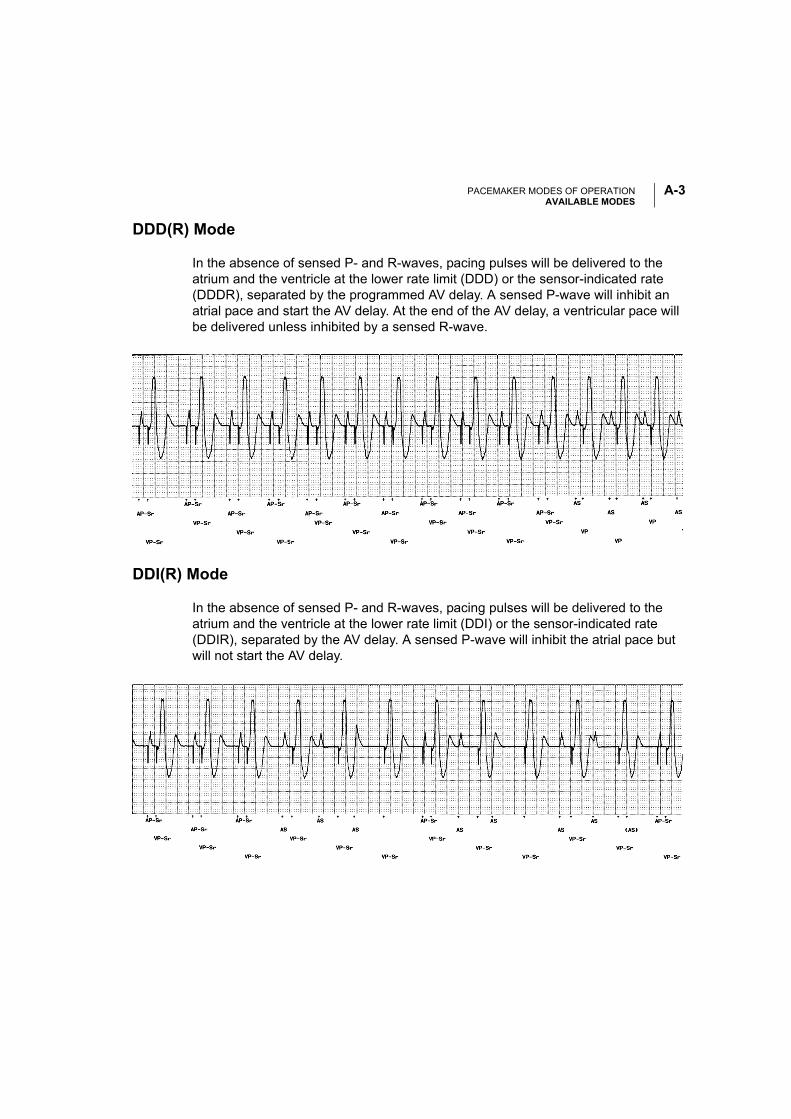
PACEMAKER MODES OF OPERATIONAVAILABLE MODES
A-3
DDD(R) Mode
In the absence of sensed P- and R-waves, pacing pulses will be delivered to the atrium and the ventricle at the lower rate limit (DDD) or the sensor-indicated rate (DDDR), separated by the programmed AV delay. A sensed P-wave will inhibit an atrial pace and start the AV delay. At the end of the AV delay, a ventricular pace will be delivered unless inhibited by a sensed R-wave.
DDI(R) Mode
In the absence of sensed P- and R-waves, pacing pulses will be delivered to the atrium and the ventricle at the lower rate limit (DDI) or the sensor-indicated rate (DDIR), separated by the AV delay. A sensed P-wave will inhibit the atrial pace but will not start the AV delay.
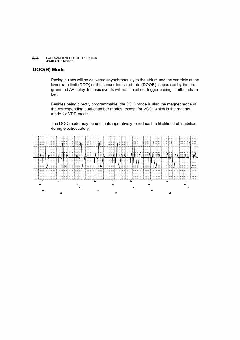
PACEMAKER MODES OF OPERATIONAVAILABLE MODES
A-4
DOO(R) Mode
Pacing pulses will be delivered asynchronously to the atrium and the ventricle at the lower rate limit (DOO) or the sensor-indicated rate (DOOR), separated by the pro-grammed AV delay. Intrinsic events will not inhibit nor trigger pacing in either cham-ber.
Besides being directly programmable, the DOO mode is also the magnet mode of the corresponding dual-chamber modes, except for VOO, which is the magnet mode for VDD mode.
The DOO mode may be used intraoperatively to reduce the likelihood of inhibition during electrocautery.
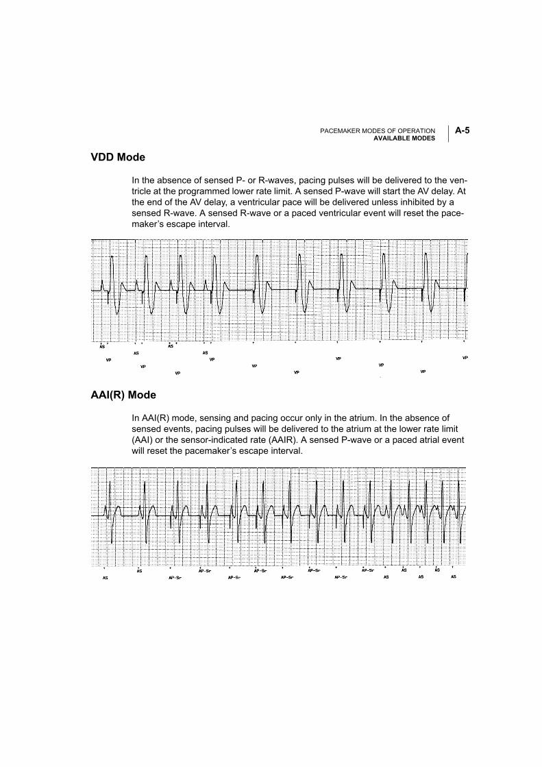
PACEMAKER MODES OF OPERATIONAVAILABLE MODES
A-5
VDD Mode
In the absence of sensed P- or R-waves, pacing pulses will be delivered to the ven-tricle at the programmed lower rate limit. A sensed P-wave will start the AV delay. At the end of the AV delay, a ventricular pace will be delivered unless inhibited by a sensed R-wave. A sensed R-wave or a paced ventricular event will reset the pace-maker’s escape interval.
AAI(R) Mode
In AAI(R) mode, sensing and pacing occur only in the atrium. In the absence of sensed events, pacing pulses will be delivered to the atrium at the lower rate limit (AAI) or the sensor-indicated rate (AAIR). A sensed P-wave or a paced atrial event will reset the pacemaker’s escape interval.
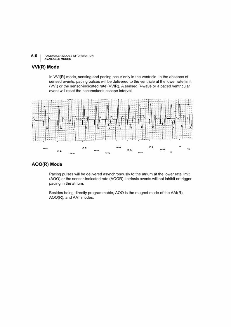
PACEMAKER MODES OF OPERATIONAVAILABLE MODES
A-6
VVI(R) Mode
In VVI(R) mode, sensing and pacing occur only in the ventricle. In the absence of sensed events, pacing pulses will be delivered to the ventricle at the lower rate limit (VVI) or the sensor-indicated rate (VVIR). A sensed R-wave or a paced ventricular event will reset the pacemaker’s escape interval.
AOO(R) Mode
Pacing pulses will be delivered asynchronously to the atrium at the lower rate limit (AOO) or the sensor-indicated rate (AOOR). Intrinsic events will not inhibit or trigger pacing in the atrium.
Besides being directly programmable, AOO is the magnet mode of the AAI(R), AOO(R), and AAT modes.
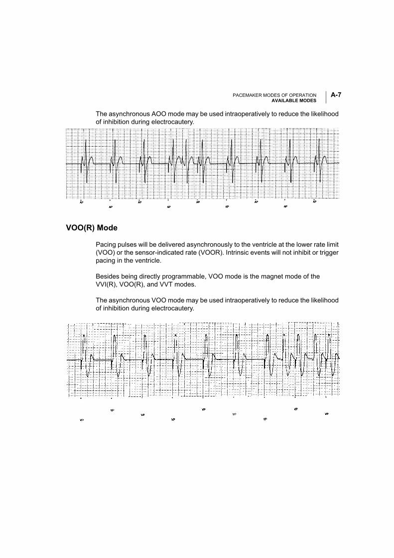
PACEMAKER MODES OF OPERATIONAVAILABLE MODES
A-7
The asynchronous AOO mode may be used intraoperatively to reduce the likelihood of inhibition during electrocautery.
VOO(R) Mode
Pacing pulses will be delivered asynchronously to the ventricle at the lower rate limit (VOO) or the sensor-indicated rate (VOOR). Intrinsic events will not inhibit or trigger pacing in the ventricle.
Besides being directly programmable, VOO mode is the magnet mode of the VVI(R), VOO(R), and VVT modes.
The asynchronous VOO mode may be used intraoperatively to reduce the likelihood of inhibition during electrocautery.
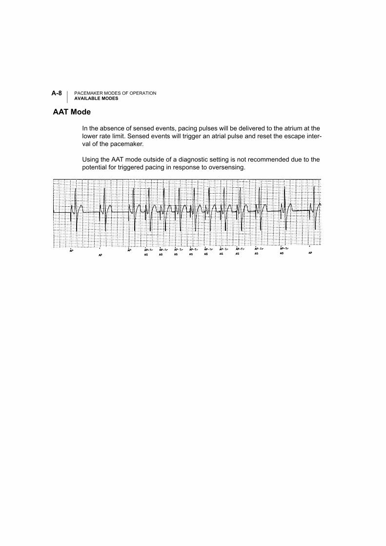
PACEMAKER MODES OF OPERATIONAVAILABLE MODES
A-8
AAT Mode
In the absence of sensed events, pacing pulses will be delivered to the atrium at the lower rate limit. Sensed events will trigger an atrial pulse and reset the escape inter-val of the pacemaker.
Using the AAT mode outside of a diagnostic setting is not recommended due to the potential for triggered pacing in response to oversensing.
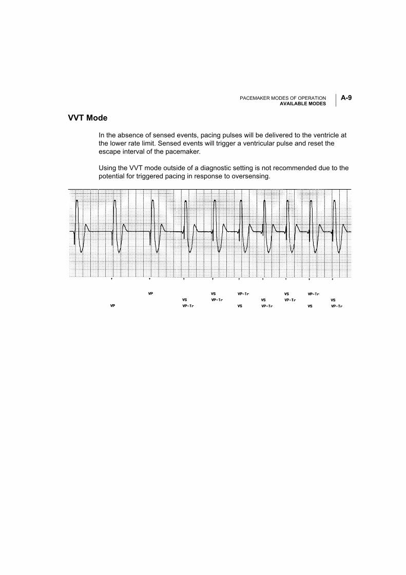
PACEMAKER MODES OF OPERATIONAVAILABLE MODES
A-9
VVT Mode
In the absence of sensed events, pacing pulses will be delivered to the ventricle at the lower rate limit. Sensed events will trigger a ventricular pulse and reset the escape interval of the pacemaker.
Using the VVT mode outside of a diagnostic setting is not recommended due to the potential for triggered pacing in response to oversensing.

PACEMAKER MODES OF OPERATIONAVAILABLE MODES
A-10
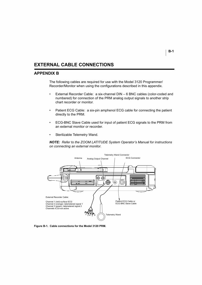
B-1
EXTERNAL CABLE CONNECTIONS
APPENDIX B
The following cables are required for use with the Model 3120 Programmer/Recorder/Monitor when using the configurations described in this appendix.
• External Recorder Cable: a six-channel DIN – 6 BNC cables (color-coded and numbered) for connection of the PRM analog output signals to another strip chart recorder or monitor.
• Patient ECG Cable: a six-pin amphenol ECG cable for connecting the patient directly to the PRM.
• ECG-BNC Slave Cable used for input of patient ECG signals to the PRM from an external monitor or recorder.
• Sterilizable Telemetry Wand.
NOTE: Refer to the ZOOM LATITUDE System Operator’s Manual for instructions on connecting an external monitor.
Figure B-1. Cable connections for the Model 3120 PRM.
Patient ECG Cable orECG BNC Slave Cable
External Recorder Cable:
Channel 1 (red)-surface ECGChannel 2 (orange) -telemetered signal 1Channel 3 (green) -telemetered signal 2Channels 4,5,6-not active
12 3 4 5 6 Telemetry Wand
ECG Connector
Telemetry Wand Connector
Analog Output Channel Antenna
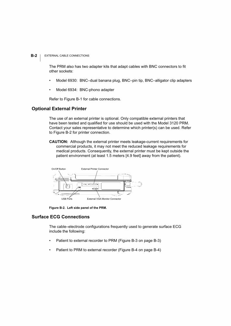
EXTERNAL CABLE CONNECTIONSB-2
The PRM also has two adapter kits that adapt cables with BNC connectors to fit other sockets:
• Model 6930: BNC–dual banana plug, BNC–pin tip, BNC–alligator clip adapters
• Model 6934: BNC-phono adapter
Refer to Figure B-1 for cable connections.
Optional External Printer
The use of an external printer is optional. Only compatible external printers that have been tested and qualified for use should be used with the Model 3120 PRM. Contact your sales representative to determine which printer(s) can be used. Refer to Figure B-2 for printer connection.
CAUTION: Although the external printer meets leakage-current requirements for commercial products, it may not meet the reduced leakage requirements for medical products. Consequently, the external printer must be kept outside the patient environment (at least 1.5 meters [4.9 feet] away from the patient).
Surface ECG Connections
The cable–electrode configurations frequently used to generate surface ECG include the following:
• Patient to external recorder to PRM (Figure B-3 on page B-3)
• Patient to PRM to external recorder (Figure B-4 on page B-4)
Figure B-2. Left side panel of the PRM.
On/Off Button
External VGA Monitor Connector
External Printer Connector
USB Ports
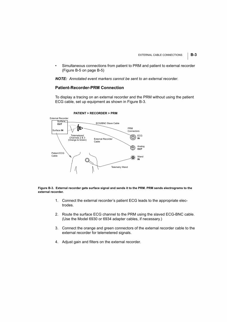
EXTERNAL CABLE CONNECTIONS B-3
• Simultaneous connections from patient to PRM and patient to external recorder (Figure B-5 on page B-5)
NOTE: Annotated event markers cannot be sent to an external recorder.
Patient-Recorder-PRM Connection
To display a tracing on an external recorder and the PRM without using the patient ECG cable, set up equipment as shown in Figure B-3.
1. Connect the external recorder’s patient ECG leads to the appropriate elec-trodes.
2. Route the surface ECG channel to the PRM using the slaved ECG-BNC cable. (Use the Model 6930 or 6934 adapter cables, if necessary.)
3. Connect the orange and green connectors of the external recorder cable to the external recorder for telemetered signals.
4. Adjust gain and filters on the external recorder.
Figure B-3. External recorder gets surface signal and sends it to the PRM. PRM sends electrograms to the external recorder.
PATIENT > RECORDER > PRM
Telemetry Wand
Patient ECG Cable
External Recorder
ECG/BNC Slave Cable
External Recorder Cable
PRMConnectors
ECG IN
WandIN
AnalogOUT
Surface IN
Surface OUT
TelemeteredChannels 2 & 3
(Orange & Green)
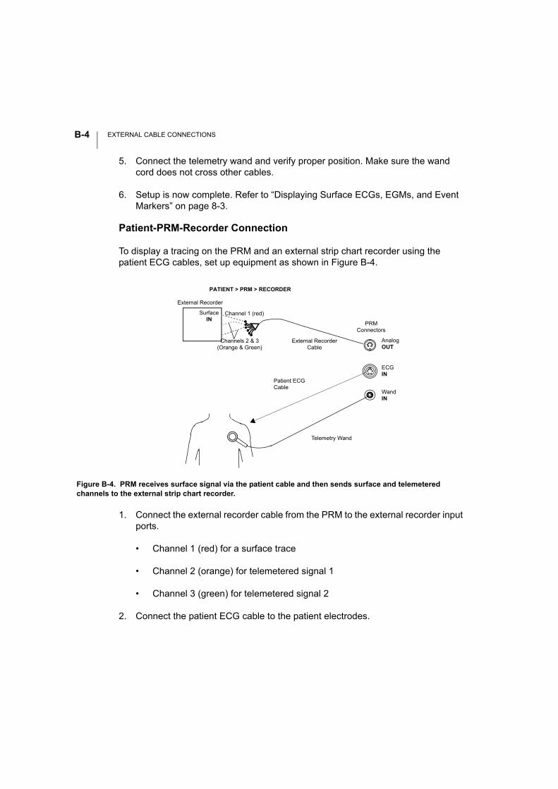
EXTERNAL CABLE CONNECTIONSB-4
5. Connect the telemetry wand and verify proper position. Make sure the wand cord does not cross other cables.
6. Setup is now complete. Refer to “Displaying Surface ECGs, EGMs, and Event Markers” on page 8-3.
Patient-PRM-Recorder Connection
To display a tracing on the PRM and an external strip chart recorder using the patient ECG cables, set up equipment as shown in Figure B-4.
1. Connect the external recorder cable from the PRM to the external recorder input ports.
• Channel 1 (red) for a surface trace
• Channel 2 (orange) for telemetered signal 1
• Channel 3 (green) for telemetered signal 2
2. Connect the patient ECG cable to the patient electrodes.
Figure B-4. PRM receives surface signal via the patient cable and then sends surface and telemetered channels to the external strip chart recorder.
Telemetry Wand
Patient ECG Cable
External Recorder
External Recorder Cable
PATIENT > PRM > RECORDER
Channel 1 (red)
PRMConnectors
ECGIN
WandIN
AnalogOUT
Surface IN
Channels 2 & 3 (Orange & Green)
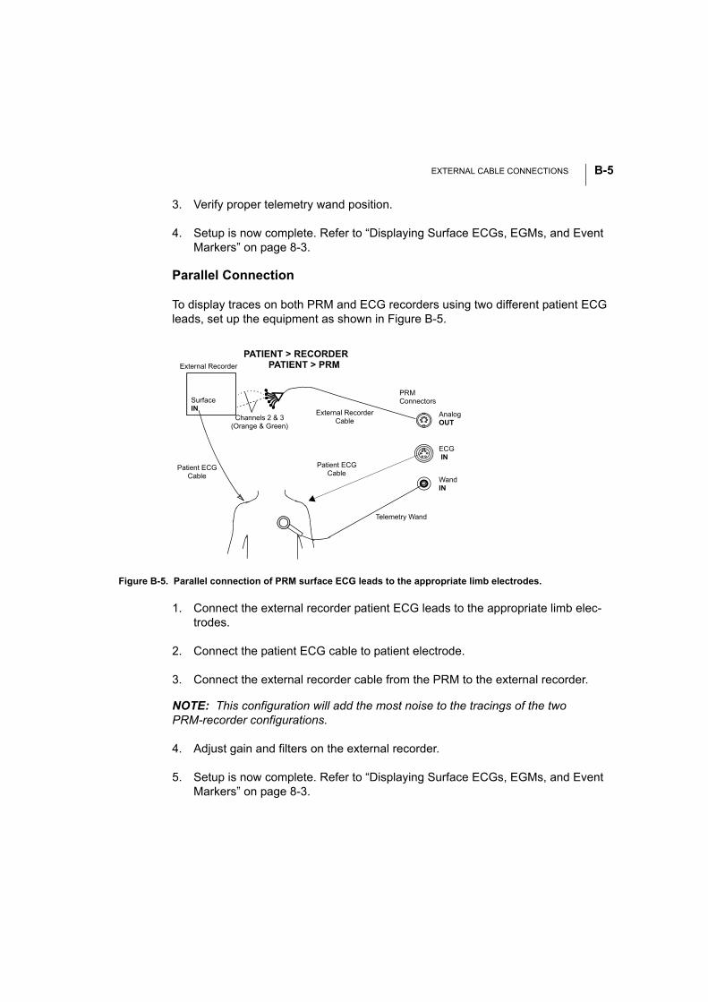
EXTERNAL CABLE CONNECTIONS B-5
3. Verify proper telemetry wand position.
4. Setup is now complete. Refer to “Displaying Surface ECGs, EGMs, and Event Markers” on page 8-3.
Parallel Connection
To display traces on both PRM and ECG recorders using two different patient ECG leads, set up the equipment as shown in Figure B-5.
1. Connect the external recorder patient ECG leads to the appropriate limb elec-trodes.
2. Connect the patient ECG cable to patient electrode.
3. Connect the external recorder cable from the PRM to the external recorder.
NOTE: This configuration will add the most noise to the tracings of the two PRM-recorder configurations.
4. Adjust gain and filters on the external recorder.
5. Setup is now complete. Refer to “Displaying Surface ECGs, EGMs, and Event Markers” on page 8-3.
Figure B-5. Parallel connection of PRM surface ECG leads to the appropriate limb electrodes.
Telemetry Wand
Patient ECG Cable
External Recorder
External Recorder Cable
PRMConnectors
ECG IN
WandIN
AnalogOUT
Surface IN
Patient ECG Cable
PATIENT > RECORDERPATIENT > PRM
Channels 2 & 3 (Orange & Green)

EXTERNAL CABLE CONNECTIONSB-6
NOTE: The right leg electrode on the patient ECG cable is a driven ground. When connecting the PRM and an external ECG monitor in parallel, the driven grounds for the two instruments must be connected to the same patient limb (e.g., right leg); oth-erwise noise problems will occur.
Troubleshooting
No Tracing on PRM
If the hookups described above do not yield a tracing on the PRM, check the following PRM functions:
1. Make sure the appropriate sweep speed on the ECG window is selected.
2. Ensure the traces selection is made (surface ECGs, telemetered EGMs, and/or markers).
3. Recheck cable connections as shown in figures above.
If the hook-ups do not yield a satisfactory tracing, contact Technical Services for assistance.
Noisy Tracing
If the hookups yield a recording with background noise, check the following:
1. Check the cable connections.
2. Check the electrode and skin conditions and electrode placement.
3. Route the ECG cable directly from the PRM to the patient and away from power cords, the telemetry wand cord, and other room equipment.
Optimizing the Quality of ECG Tracings
To improve the clarity of the ECG tracings and optimize the signals, try one or more of the following procedures:
• Change the surface ECG amplitude to 2x gain.

EXTERNAL CABLE CONNECTIONS B-7
• Route the ECG cables away from other equipment. Unwrap the cables from the power cord or telemetry wand cable if they are intertwined.
• Ensure that there is good contact between the skin and the electrodes. Prep-ping the skin with alcohol and using electrode gel can make a significant differ-ence in ECG signal quality.

EXTERNAL CABLE CONNECTIONSB-8
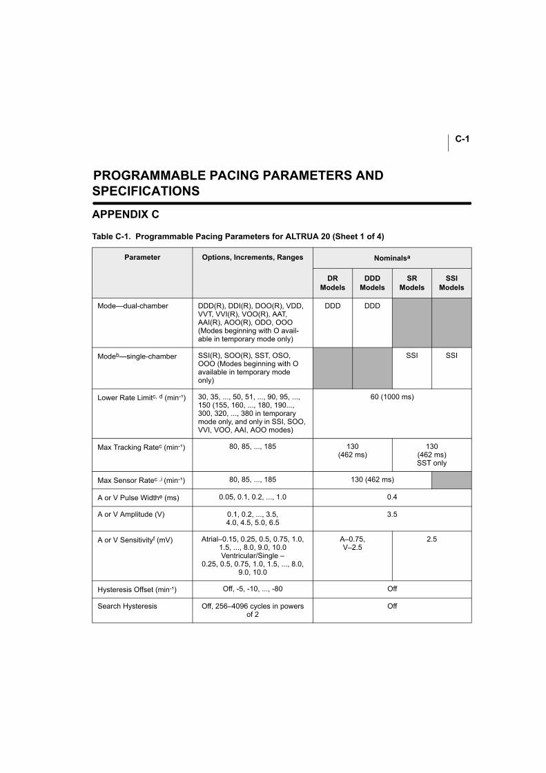
C-1
PROGRAMMABLE PACING PARAMETERS AND SPECIFICATIONS
APPENDIX C
Table C-1. Programmable Pacing Parameters for ALTRUA 20 (Sheet 1 of 4)
Parameter Options, Increments, Ranges Nominalsa
DRModels
DDDModels
SRModels
SSIModels
Mode—dual-chamber DDD(R), DDI(R), DOO(R), VDD, VVT, VVI(R), VOO(R), AAT, AAI(R), AOO(R), ODO, OOO (Modes beginning with O avail-able in temporary mode only)
DDD DDD
Modeb—single-chamber SSI(R), SOO(R), SST, OSO, OOO (Modes beginning with O available in temporary mode only)
SSI SSI
Lower Rate Limitc, d (min-¹) 30, 35, ..., 50, 51, ..., 90, 95, ..., 150 (155, 160, ..., 180, 190..., 300, 320, ..., 380 in temporary mode only, and only in SSI, SOO, VVI, VOO, AAI, AOO modes)
60 (1000 ms)
Max Tracking Ratec (min-¹) 80, 85, ..., 185 130(462 ms)
130(462 ms)SST only
Max Sensor Ratec ,i (min-¹) 80, 85, ..., 185 130 (462 ms)
A or V Pulse Widthe (ms) 0.05, 0.1, 0.2, ..., 1.0 0.4
A or V Amplitude (V) 0.1, 0.2, ..., 3.5,4.0, 4.5, 5.0, 6.5
3.5
A or V Sensitivityf (mV) Atrial–0.15, 0.25, 0.5, 0.75, 1.0, 1.5, ..., 8.0, 9.0, 10.0Ventricular/Single –
0.25, 0.5, 0.75, 1.0, 1.5, ..., 8.0, 9.0, 10.0
A–0.75, V–2.5
2.5
Hysteresis Offset (min-¹) Off, -5, -10, ..., -80 Off
Search Hysteresis Off, 256–4096 cycles in powers of 2
Off
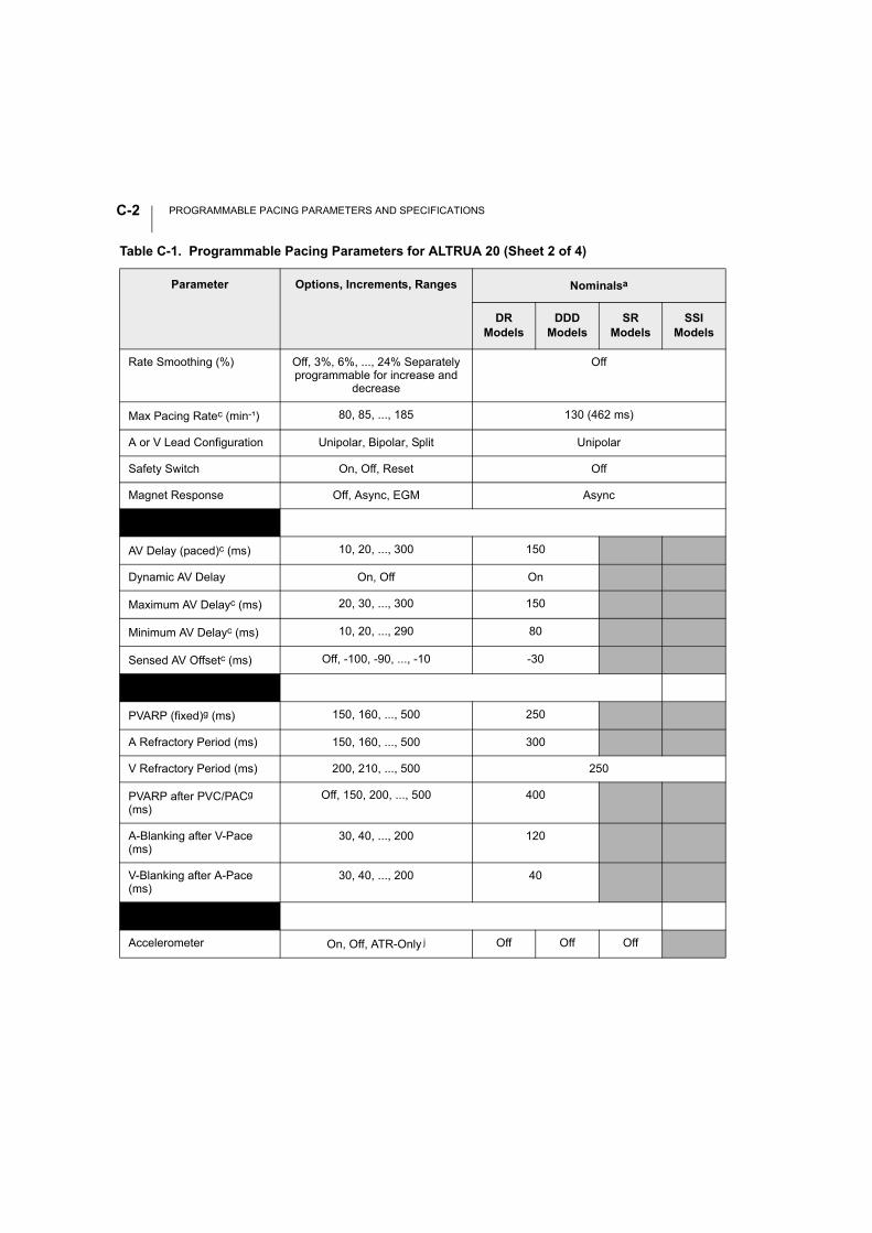
PROGRAMMABLE PACING PARAMETERS AND SPECIFICATIONSC-2
Rate Smoothing (%) Off, 3%, 6%, ..., 24% Separately programmable for increase and
decrease
Off
Max Pacing Ratec (min-¹) 80, 85, ..., 185 130 (462 ms)
A or V Lead Configuration Unipolar, Bipolar, Split Unipolar
Safety Switch On, Off, Reset Off
Magnet Response Off, Async, EGM Async
AV Delayg
AV Delay (paced)c (ms) 10, 20, ..., 300 150
Dynamic AV Delay On, Off On
Maximum AV Delayc (ms) 20, 30, ..., 300 150
Minimum AV Delayc (ms) 10, 20, ..., 290 80
Sensed AV Offsetc (ms) Off, -100, -90, ..., -10 -30
Refractory Periodsh
PVARP (fixed)g (ms) 150, 160, ..., 500 250
A Refractory Period (ms) 150, 160, ..., 500 300
V Refractory Period (ms) 200, 210, ..., 500 250
PVARP after PVC/PACg (ms)
Off, 150, 200, ..., 500 400
A-Blanking after V-Pace (ms)
30, 40, ..., 200 120
V-Blanking after A-Pace (ms)
30, 40, ..., 200 40
Sensorsi
Accelerometer On, Off, ATR-Only j Off Off Off
Table C-1. Programmable Pacing Parameters for ALTRUA 20 (Sheet 2 of 4)
Parameter Options, Increments, Ranges Nominalsa
DRModels
DDDModels
SRModels
SSIModels
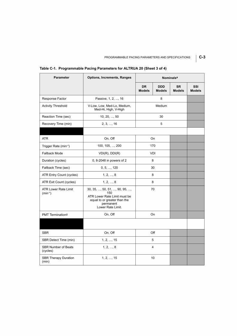
PROGRAMMABLE PACING PARAMETERS AND SPECIFICATIONS C-3
Response Factor Passive, 1, 2, ..., 16 8
Activity Threshold V-Low, Low, Med-Lo, Medium, Med-Hi, High, V-High
Medium
Reaction Time (sec) 10, 20, ..., 50 30
Recovery Time (min) 2, 3, ..., 16 5
A-Tachy Response (ATR)g
ATR On, Off On
Trigger Rate (min-¹) 100, 105, ..., 200 170
Fallback Mode VDI(R), DDI(R) VDI
Duration (cycles) 0, 8-2048 in powers of 2 8
Fallback Time (sec) 0, 5, ..., 120 30
ATR Entry Count (cycles) 1, 2, ..., 8 8
ATR Exit Count (cycles) 1, 2, ..., 8 8
ATR Lower Rate Limit (min-¹)
30, 35, ..., 50, 51, ..., 90, 95, ..., 150
ATR Lower Rate Limit must be equal to or greater than the
permanentLower Rate Limit.
70
PMT Terminationg On, Off On
Sudden Brady Response (SBR)
SBR On, Off Off
SBR Detect Time (min) 1, 2, ..., 15 5
SBR Number of Beats (cycles)
1, 2, ..., 8 4
SBR Therapy Duration (min)
1, 2, ..., 15 10
Table C-1. Programmable Pacing Parameters for ALTRUA 20 (Sheet 3 of 4)
Parameter Options, Increments, Ranges Nominalsa
DRModels
DDDModels
SRModels
SSIModels
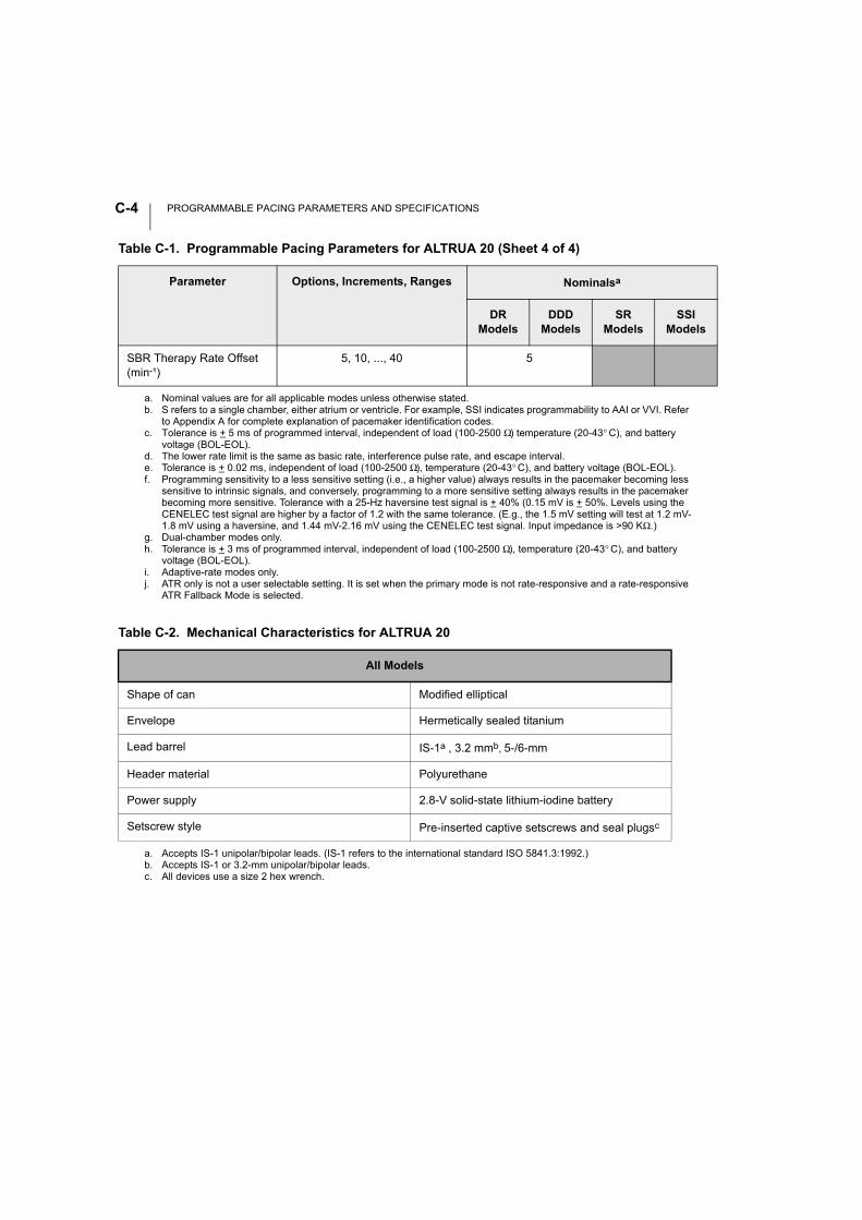
PROGRAMMABLE PACING PARAMETERS AND SPECIFICATIONSC-4
SBR Therapy Rate Offset (min-¹)
5, 10, ..., 40 5
a. Nominal values are for all applicable modes unless otherwise stated.b. S refers to a single chamber, either atrium or ventricle. For example, SSI indicates programmability to AAI or VVI. Refer
to Appendix A for complete explanation of pacemaker identification codes.c. Tolerance is + 5 ms of programmed interval, independent of load (100-2500 Ω) temperature (20-43° C), and battery
voltage (BOL-EOL).d. The lower rate limit is the same as basic rate, interference pulse rate, and escape interval. e. Tolerance is + 0.02 ms, independent of load (100-2500 Ω), temperature (20-43° C), and battery voltage (BOL-EOL).f. Programming sensitivity to a less sensitive setting (i.e., a higher value) always results in the pacemaker becoming less
sensitive to intrinsic signals, and conversely, programming to a more sensitive setting always results in the pacemaker becoming more sensitive. Tolerance with a 25-Hz haversine test signal is + 40% (0.15 mV is + 50%. Levels using the CENELEC test signal are higher by a factor of 1.2 with the same tolerance. (E.g., the 1.5 mV setting will test at 1.2 mV-1.8 mV using a haversine, and 1.44 mV-2.16 mV using the CENELEC test signal. Input impedance is >90 KΩ.)
g. Dual-chamber modes only.h. Tolerance is + 3 ms of programmed interval, independent of load (100-2500 Ω), temperature (20-43° C), and battery
voltage (BOL-EOL).i. Adaptive-rate modes only.j. ATR only is not a user selectable setting. It is set when the primary mode is not rate-responsive and a rate-responsive
ATR Fallback Mode is selected.
Table C-2. Mechanical Characteristics for ALTRUA 20
All Models
Shape of can Modified elliptical
Envelope Hermetically sealed titanium
Lead barrel IS-1a , 3.2 mmb, 5-/6-mm
a. Accepts IS-1 unipolar/bipolar leads. (IS-1 refers to the international standard ISO 5841.3:1992.)b. Accepts IS-1 or 3.2-mm unipolar/bipolar leads.
Header material Polyurethane
Power supply 2.8-V solid-state lithium-iodine battery
Setscrew style Pre-inserted captive setscrews and seal plugsc
c. All devices use a size 2 hex wrench.
Table C-1. Programmable Pacing Parameters for ALTRUA 20 (Sheet 4 of 4)
Parameter Options, Increments, Ranges Nominalsa
DRModels
DDDModels
SRModels
SSIModels
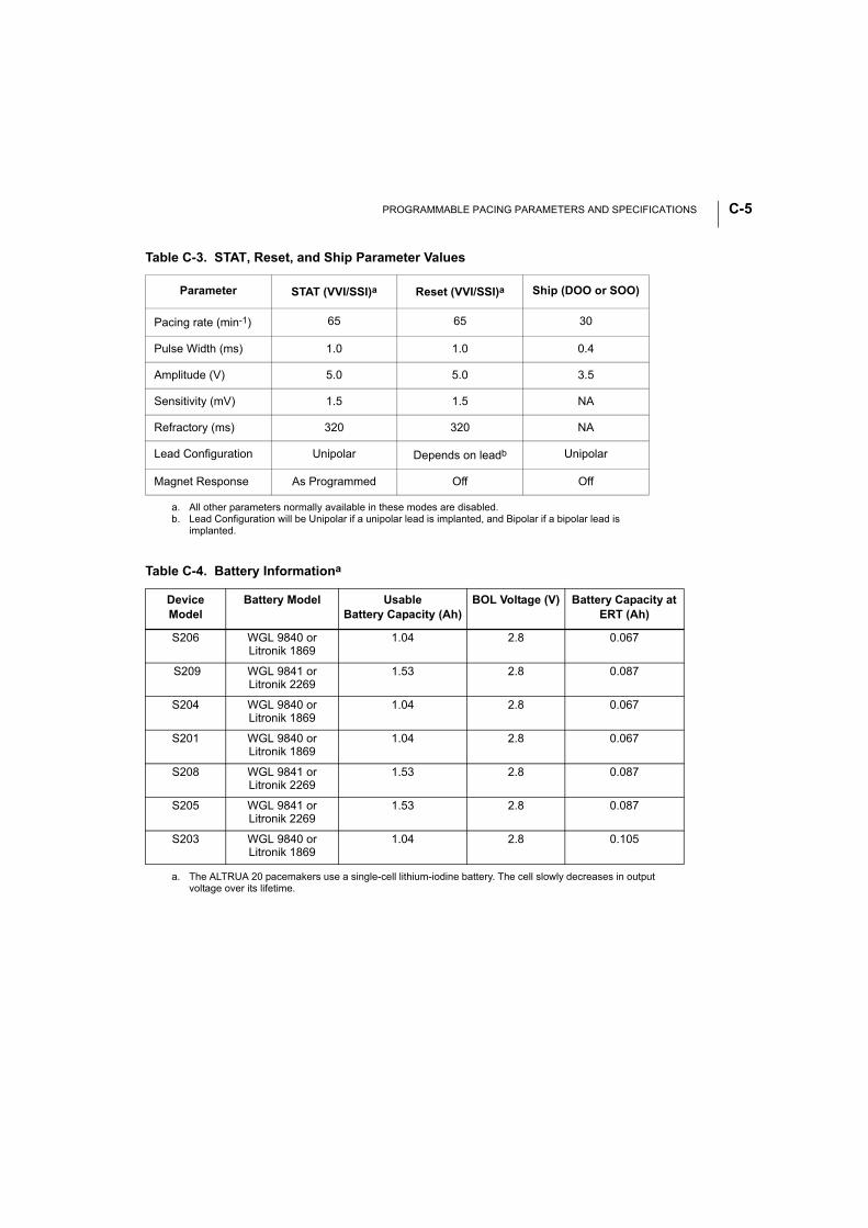
PROGRAMMABLE PACING PARAMETERS AND SPECIFICATIONS C-5
Table C-3. STAT, Reset, and Ship Parameter Values
Parameter STAT (VVI/SSI)a
a. All other parameters normally available in these modes are disabled.
Reset (VVI/SSI)a Ship (DOO or SOO)
Pacing rate (min-1) 65 65 30
Pulse Width (ms) 1.0 1.0 0.4
Amplitude (V) 5.0 5.0 3.5
Sensitivity (mV) 1.5 1.5 NA
Refractory (ms) 320 320 NA
Lead Configuration Unipolar Depends on leadb
b. Lead Configuration will be Unipolar if a unipolar lead is implanted, and Bipolar if a bipolar lead is implanted.
Unipolar
Magnet Response As Programmed Off Off
Table C-4. Battery Informationa
a. The ALTRUA 20 pacemakers use a single-cell lithium-iodine battery. The cell slowly decreases in output voltage over its lifetime.
DeviceModel
Battery Model Usable Battery Capacity (Ah)
BOL Voltage (V) Battery Capacity at ERT (Ah)
S206 WGL 9840 orLitronik 1869
1.04 2.8 0.067
S209 WGL 9841 orLitronik 2269
1.53 2.8 0.087
S204 WGL 9840 orLitronik 1869
1.04 2.8 0.067
S201 WGL 9840 orLitronik 1869
1.04 2.8 0.067
S208 WGL 9841 orLitronik 2269
1.53 2.8 0.087
S205 WGL 9841 orLitronik 2269
1.53 2.8 0.087
S203 WGL 9840 orLitronik 1869
1.04 2.8 0.105
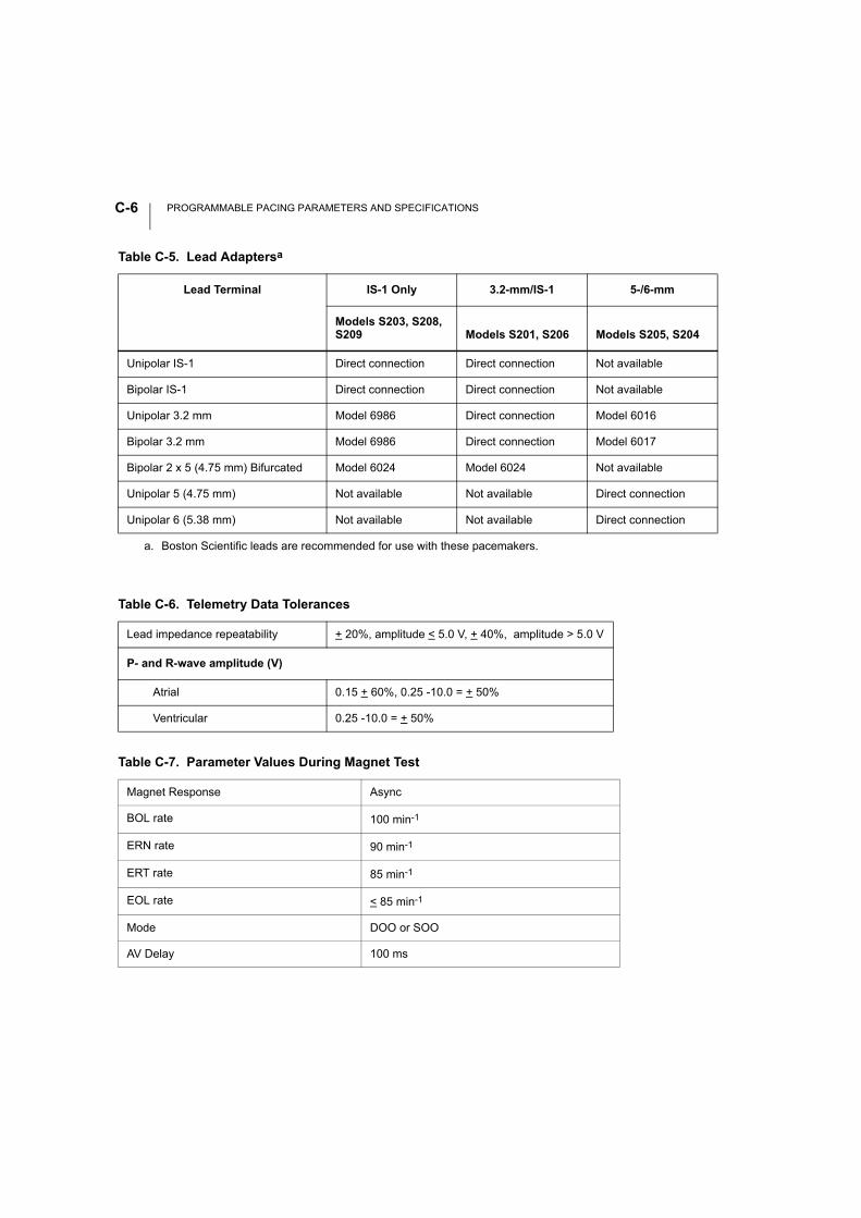
PROGRAMMABLE PACING PARAMETERS AND SPECIFICATIONSC-6
Table C-5. Lead Adaptersa
a. Boston Scientific leads are recommended for use with these pacemakers.
Lead Terminal IS-1 Only 3.2-mm/IS-1 5-/6-mm
Models S203, S208, S209 Models S201, S206 Models S205, S204
Unipolar IS-1 Direct connection Direct connection Not available
Bipolar IS-1 Direct connection Direct connection Not available
Unipolar 3.2 mm Model 6986 Direct connection Model 6016
Bipolar 3.2 mm Model 6986 Direct connection Model 6017
Bipolar 2 x 5 (4.75 mm) Bifurcated Model 6024 Model 6024 Not available
Unipolar 5 (4.75 mm) Not available Not available Direct connection
Unipolar 6 (5.38 mm) Not available Not available Direct connection
Table C-6. Telemetry Data Tolerances
Lead impedance repeatability + 20%, amplitude < 5.0 V, + 40%, amplitude > 5.0 V
P- and R-wave amplitude (V)
Atrial 0.15 + 60%, 0.25 -10.0 = + 50%
Ventricular 0.25 -10.0 = + 50%
Table C-7. Parameter Values During Magnet Test
Magnet Response Async
BOL rate 100 min-1
ERN rate 90 min-1
ERT rate 85 min-1
EOL rate < 85 min-1
Mode DOO or SOO
AV Delay 100 ms
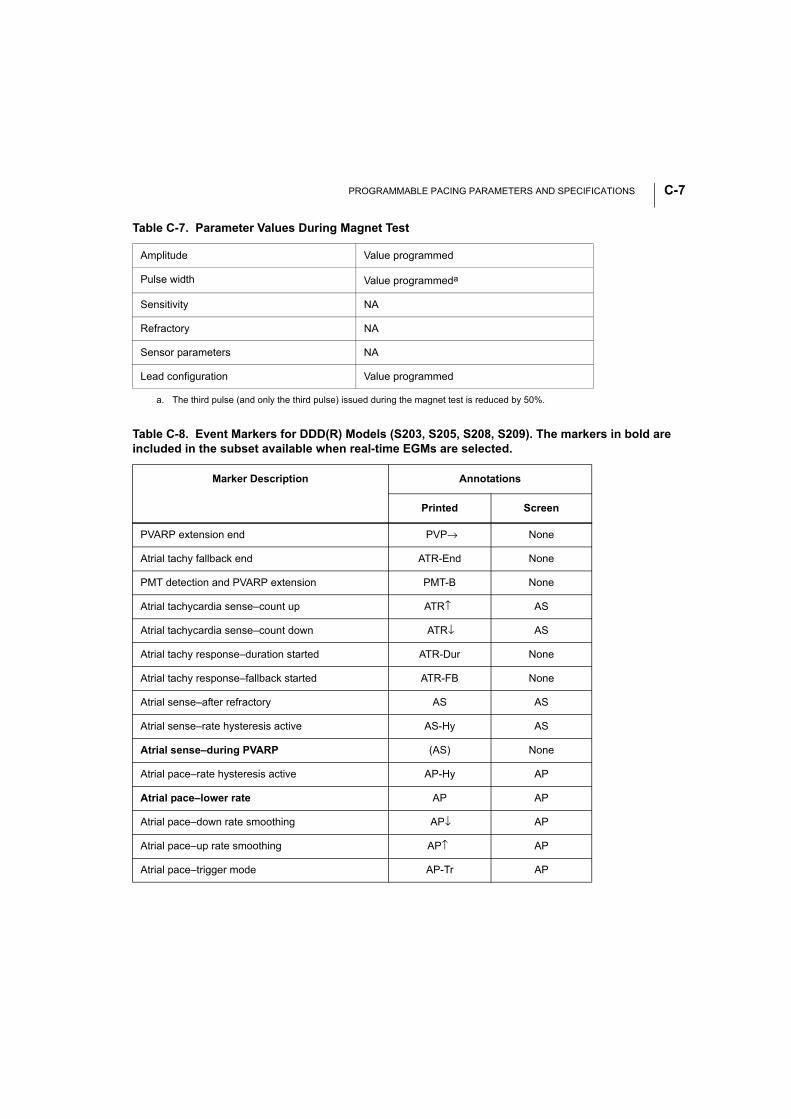
PROGRAMMABLE PACING PARAMETERS AND SPECIFICATIONS C-7
Amplitude Value programmed
Pulse width Value programmeda
Sensitivity NA
Refractory NA
Sensor parameters NA
Lead configuration Value programmed
a. The third pulse (and only the third pulse) issued during the magnet test is reduced by 50%.
Table C-8. Event Markers for DDD(R) Models (S203, S205, S208, S209). The markers in bold are included in the subset available when real-time EGMs are selected.
Marker Description Annotations
Printed Screen
PVARP extension end PVP→ None
Atrial tachy fallback end ATR-End None
PMT detection and PVARP extension PMT-B None
Atrial tachycardia sense–count up ATR↑ AS
Atrial tachycardia sense–count down ATR↓ AS
Atrial tachy response–duration started ATR-Dur None
Atrial tachy response–fallback started ATR-FB None
Atrial sense–after refractory AS AS
Atrial sense–rate hysteresis active AS-Hy AS
Atrial sense–during PVARP (AS) None
Atrial pace–rate hysteresis active AP-Hy AP
Atrial pace–lower rate AP AP
Atrial pace–down rate smoothing AP↓ AP
Atrial pace–up rate smoothing AP↑ AP
Atrial pace–trigger mode AP-Tr AP
Table C-7. Parameter Values During Magnet Test
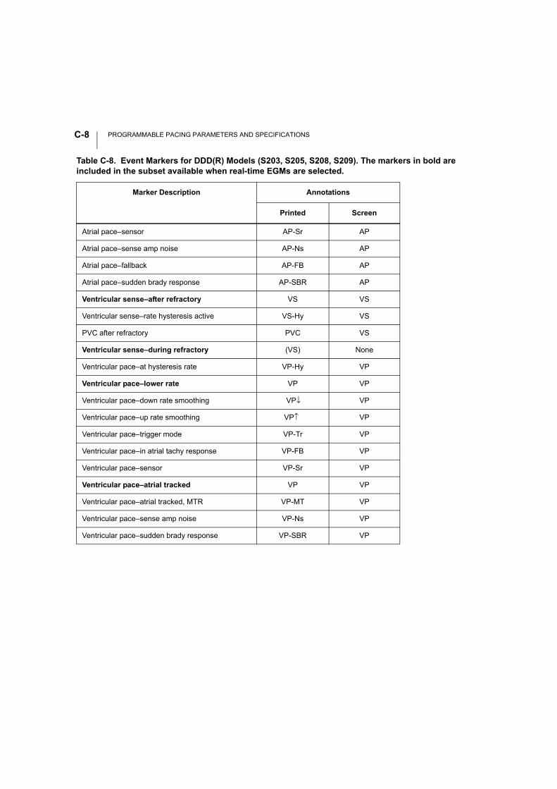
PROGRAMMABLE PACING PARAMETERS AND SPECIFICATIONSC-8
Atrial pace–sensor AP-Sr AP
Atrial pace–sense amp noise AP-Ns AP
Atrial pace–fallback AP-FB AP
Atrial pace–sudden brady response AP-SBR AP
Ventricular sense–after refractory VS VS
Ventricular sense–rate hysteresis active VS-Hy VS
PVC after refractory PVC VS
Ventricular sense–during refractory (VS) None
Ventricular pace–at hysteresis rate VP-Hy VP
Ventricular pace–lower rate VP VP
Ventricular pace–down rate smoothing VP↓ VP
Ventricular pace–up rate smoothing VP↑ VP
Ventricular pace–trigger mode VP-Tr VP
Ventricular pace–in atrial tachy response VP-FB VP
Ventricular pace–sensor VP-Sr VP
Ventricular pace–atrial tracked VP VP
Ventricular pace–atrial tracked, MTR VP-MT VP
Ventricular pace–sense amp noise VP-Ns VP
Ventricular pace–sudden brady response VP-SBR VP
Table C-8. Event Markers for DDD(R) Models (S203, S205, S208, S209). The markers in bold are included in the subset available when real-time EGMs are selected.
Marker Description Annotations
Printed Screen
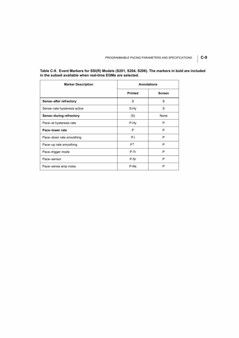
PROGRAMMABLE PACING PARAMETERS AND SPECIFICATIONS C-9
Table C-9. Event Markers for SSI(R) Models (S201, S204, S206). The markers in bold are included in the subset available when real-time EGMs are selected.
Marker Description Annotations
Printed Screen
Sense–after refractory S S
Sense–rate hysteresis active S-Hy S
Sense–during refractory (S) None
Pace–at hysteresis rate P-Hy P
Pace–lower rate P P
Pace–down rate smoothing P↓ P
Pace–up rate smoothing P↑ P
Pace–trigger mode P-Tr P
Pace–sensor P-Sr P
Pace–sense amp noise P-Ns P

PROGRAMMABLE PACING PARAMETERS AND SPECIFICATIONSC-10

INDEX
Numerics2:1 block 6-9
AAbout utility 5-6About, file menu option 5-22Accelerometer 3-2, 6-16Activity log 7-29Activity threshold 6-19Adapters
for PRM cables B-2Adaptive-rate pacing 6-16Amplitude 6-12Arrhythmia logbook 7-14
setup screen 7-9Arrow buttons. See ButtonsA-tachy response 6-24ATR 6-17
See also Atrial tachy responseAtrial tachy response 6-7, 6-17, 6-24
duration 6-26lower rate limit 6-29trigger rate 6-24
Atrial-based timing 6-7See also Timing intervals
Automatic lead configuration 6-42See also Safety switch
Automatic lead implant detection 2-8AV delay 6-11
dynamic 6-44maximum 6-44, 6-45minimum 6-44, 6-46
BBackup VVI pacing 7-38Battery 4-2Battery status 4-3, 6-53Battery test 7-21
Beat to beatrecording method 7-13
Beat to beat dataretrieval 7-33working with 7-34
Bipolar configuration lock-out 6-41Blanking 6-49
atrial 6-50ventricular 6-49
Brady parameters screen 6-2Burst
manual burst pacing 7-39Buttons
cancel 5-14close 5-14induce 7-39toolbox 5-13
CCancel button. See ButtonsCancel changes 6-3Cellular phones 1-11Check box 5-12clinical events 7-2Contraindications
by mode A-2Copy disk 5-21Counters 7-18
DDaily measurement 7-29
amplitude 7-29displaying 7-30intrinsic amplitude 7-29lead impedance 7-29
Daily measurementsP- and R-wave measurements 7-29
Date and time, setting 5-7, 5-22
DEMO logo 5-12Demo mode 5-6, 5-8Detection counter 6-25Diagnostics 7-1Diagnostic x-ray 1-10Disk
patient data diskcopy 5-21
Dynamic AV delay 6-11, 6-44See also AV delay
EECG
displaying 5-13, 8-3optimizing quality B-6parallel connection B-5patient-ECG-PRM connection B-3patient-PRM-ECG connection B-4printing 8-5surface ECG connections B-2troubleshooting B-6
ECG icon 5-10Elective replacement time 4-5Electrograms
displaying 5-13, 8-3printing 8-5
Electronic calipers 7-16, 7-36Electrosurgical cautery 1-7End of Life 4-6Entry count 6-25EOL 4-6
See also End of LifeEP test
PES 7-38ERT 4-5
See also Elective replacement timeEvent markers
displaying 8-3printing 8-5
Exit count 6-25Explant information 4-7External defibrillation 1-9External recorder
printing 8-8
FFallback mode 6-26Fallback time 6-26File functions
quit 5-23Fluoroscopic radiation 1-10Follow-up 7-1Format disk 5-22
GGo icon 5-12
HHeart logo 5-12Hysteresis 6-31
rate 6-31search 6-33
IICD Interaction 3-2Icons
arrow 5-10check box 5-12ECG 5-10go 5-12information 5-11magnifying glass 5-12printer 5-10shortcut (hand) 5-11snapshot 5-10stop sign 5-11stop sign, clinical event 5-11
Induction

PES 7-38Information icon 5-11Institution name, setting 5-6Interactions. See Parameter interactionsInterrogate 5-8, 5-16IS-1 leads 2-7
KKeyboard, graphic 5-6, 5-17
LLead configuration 6-41
pacing 6-42sensing 6-42test 3-3
Leadsadapters 2-4connections 2-3
Lithotripsy 1-8Load initial values 6-4Load nominals 6-3Logos 5-12Longevity 4-3Loss of capture 7-28Lower rate limit 6-7LRL 6-7
See also Lower rate limit
MMagnet
mode 6-53placement 4-4, 4-5rate 2-9response 4-4, 6-53test 4-4, 4-5test parameters C-6
Magnifying glass icon 5-12Main application screen 5-8Manual burst pacing 7-37, 7-39
Marker legend 8-5Maximum pacing rate 6-37Maximum sensor rate 6-10Maximum tracking rate 6-8Measured data
at ERN 4-5at ERT 4-5
Memory check 3-3Metabolic demand 6-16Model 2892 software application 5-15Modes
list 6-5NASPE/BPEG codes A-1
MPR 6-37See also Maximum pacing rate
MSR 6-10See also Maximum sensor rate
MTR 6-8See also Maximum tracking rate
Myopotentials 6-13
NNASPE/BPEG codes A-1Noise
during telemetry 1-6, 5-17on traces B-6
Noise rejection 6-49, 6-51
OOpening instructions 2-2Oversensing 6-13
PPAC 6-48
See also Premature atrial contractionPacemaker
lead connections 2-5pocket 2-9
Pacemaker identification codes A-1
Pacemaker-mediated tachycardia 6-14, 6-30, 6-48Pacing configuration 6-42Parameter interactions 5-11, 7-8Parameters
changing values 5-17modifying 6-3
Parkinson's disease 6-19Patient counseling information 1-15PES 7-38
See also Programmed electrical stim-ulation
PG logo 5-12PMT 6-14
See also Pacemaker-mediated tachycardia
PMT termination 6-30Pocket
pacemaker 2-9, 2-10Post-ventricular atrial refractory 6-14
See also Refractory periodsPower source 4-2
See also BatteryPremature atrial contraction 6-48Premature ventricular contraction 6-48Print memory 5-22Printer icon 5-10Printing
ECG 8-5electrograms 8-5event markers 8-5external printer 8-8external recorder 8-8reports 8-9
PRMkeypad 5-15keys 5-14start up 5-2
Product Reliability 1-14Program 5-18Programmed electrical stimulation 7-38
Induction 7-38Programmer clock. See Set clockPulse duration. See Pulse widthPulse width 6-11PVARP
after PVC/PAC 6-48PVC 6-48
See also Premature ventricular con-traction
QQuick check
screen 7-3Quick start 5-5, 5-8Quit 5-23
RRadio and Telecommunications Terminal Equipment (RTTE) 1-7Radio-frequency ablation 1-7Rate hysteresis 6-31
See also HysteresisRate smoothing 6-34Reaction time 6-20Recharge cycle 3-6Recovery time 6-22Refractory periods 6-13
Atrial 6-14PVARP 6-14Ventricular 6-14
Reset 2-2, 3-3, 3-4Response factor
accelerometer 6-17RTTE 1-7Runaway protection 3-6
SSafety switch 6-42SBR 6-38
See also Sudden bradycardia re-sponse
Select function 1-4, 5-2Select PG menu 5-3Select PG option 5-8Sensed AV offset 6-46Sensing configuration 6-42Sensitivity 6-13Set institution 5-6Set programmer clock 5-7, 5-22Shortcut icon 5-11Snapshot icon 5-10Snapshot viewer 7-35Software
terminology 5-9Startup screen 5-2STAT pace 5-14Sterilization 2-3Stop sign icon 5-11
clinical event 5-11Storage 2-2Stored electrograms 7-16Submenus 6-2Sudden bradycardia response 6-38
detect time 6-39number of beats 6-39therapy duration 6-40therapy rate offset 6-39
Suture hole 2-10Sweep speed 7-36
TTelemetry
establishing communication 5-15wand 5-15
Temperature 2-2
Temporary parameters screen 7-7Therapeutic diathermy 1-9Threshold tests 7-26
manual 7-26Timing base 6-7
See also Timing intervalsTiming intervals 6-7Toolbox 5-13Transcutaneous electrical nerve stimula-tion 1-9Trending 7-32
beat-to-beat data 7-34data retrieval 7-33rate/sensor data 7-34replay 7-34storage method
continuous 7-13timer 7-13
working with data 7-34Troubleshooting, PRM hookups B-6
UUndersensing 6-13Utilities menu 5-3
main applications screen 5-19startup screen 5-6
VVentricular-based timing 6-7
See also Timing intervals
WWarranty 4-9Wenckebach 6-9, 6-35Window
general functions 5-13message 5-13moving 5-13

XXray identifier 3-2


© 2012 Boston Scientific Corporation or its affiliatesAll Rights Reserved.
357895-019 EN Europe 2012-11
*357895-019*
Boston Scientific 4100 Hamline Avenue NorthSt. Paul, MN 55112-5798 USA
Guidant Europe NV/SA; Boston Scientific Green Square, Lambroekstraat 5D1831 Diegem, Belgium
1.800.CARDIAC (227.3422)+1.651.582.4000www.bostonscientific.com
Boston Scientific (Australia) Pty LtdPO Box 332BOTANY NSW 1455 AustraliaFree Phone 1 800 676 133Free Fax 1 800 836 666
Authorized 2008