Embed Size (px)
Citation preview

INSTALLATION MANUAL
WATER SOFTENER SYSTEMS
FLEET FARM WATER SOFTENER
FLEET FARM WATER TREATMENT, 1900 PROSPECT CT. APPLETON WI 54914, 1.800.777.1426PH 920.739.9406 FAX

Table of Contents IMPORTANT SAFETY INFORMATION – READ ALL ...................................................................................... 3
INSTRUCTIONS BEFORE USING ......................................................................................................................... 3
SOFTENER ANATOMY .......................................................................... ERROR! BOOKMARK NOT DEFINED.
SPECIFICATIONS ..................................................................................................................................................... 4 FEEDWATER ................................................................................................................................................ 4 POWER ....................................................................................................................................................... 4 INSTALLATION .............................................................................................................................................. 4 SALT CAPACITY ........................................................................................................................................... 4
SETUP .......................................................................................................................................................................... 4 UNPACKING and INSPECTION ....................................................................................................................... 5 WHERE TO INSTALL THE SOFTENER .............................................................................................................. 5 HARDNESS SETTING .................................................................................................................................... 5
INSTALLATION ........................................................................................................................................................ 5
CONTROL START-UP PROCEDURES ................................................................................................................. 9
SOFTENER OPERATION ...................................................................................................................................... 10 1. BRINE DRAW / SLOW RINSE POSITION .................................................................................................... 11 2. BACKWASH POSITION ............................................................................................................................. 11 3. FAST RINSE POSITION ............................................................................................................................ 11 4. BRINE FILL ............................................................................................................................................. 11 5. SERVICE ................................................................................................................................................ 11
SERVICE ................................................................................................................................................................... 12 CLEANING IRON OUT OF THE WATER SOFTENING SYSTEM ........................................................................... 14 CHECKING FOR A SALT BRIDGE .................................................................................................................. 14 BREAKING A SALT BRIDGE .......................................................................................................................... 14 CLEANING THE INJECTOR AND SCREEN ....................................................................................................... 14
TROUBLESHOOTING ........................................................................................................................................... 15
WATER SOFTENER SYSTEM PARTS LIST ....................................... ERROR! BOOKMARK NOT DEFINED.
ERROR! BOOKMARK NOT DEFINED.

Important Safety Information – Read All
Instructions Before Using • Before beginning installation, read these instructions completely. Then obtain all the materials and
tools needed for installation. NOTE: Failure to install the Fleet Farm Water Treatment system correctly voids the
warranty. • Perform installation according to state and local plumbing codes. - Use only lead-free solder and flux for sweat-solder connections, as required by state and
federal codes. • Handle all components of the Fleet Farm Water Treatment system with care. Do not drop, drag or
turn components upside down. • Be sure the floor under the water softening system is clean and level. • The Fleet Farm Water Treatment system uses 110volt 60 Hz electrical power. - Plug transformer into an indoor 120 volt, grounded outlet. - Properly ground Fleet Farm Water Treatment system to conform with all codes and
ordinances. • Install Fleet Farm Water Treatment system in a protected area. Be sure electric outlet and
transformer do not come in contact with water. See Where to Install the Softener, in the installation section of the manual. - Do not attempt to treat water over 110°F with the Fleet Farm Water Treatment system.
Always connect the Fleet Farm Water Treatment system to the main water supply pipe before water heater.
- Do not expose Fleet Farm Water Treatment system to freezing temperatures. Water freezing in the system causes equipment damage.
- Do not install in direct sunlight. Heat from sun may cause damage. • Minimum inlet water pressure is 20 psi. Maximum inlet water pressure is 125 psi. Use pressure
reducing valve if necessary. • Use clean water softening salts only, at least 99.5% pure. Failure to use the correct salt may create a
health hazard or maintenance problems. - Use nugget, pellet, block, solar, or coarse solar salts. - Do not use granulated or ice cream making salts.
• Always keep the salt lid in place unless servicing the unit or replenishing salt.
CAUTION: Read and follow the information in this manual to minimize the risk of electric shock or personal injury. IMPORTANT! If you are unsure about installing your Fleet Farm Water Treatment water softener, contact the Fleet Farm Water Treatment helpline or consult a professional plumber. IMPORTANT! This system must be installed in compliance with applicable state and local codes, law, and regulations.
!
CAUTION: • Do not use with water that is unsafe or of unknown quality. • Test water periodically to verify that the system is
performing satisfactorily. • Discard small parts remaining after the installation. !

Specifications Feedwater ! Do not use this system on water that is microbiologically unsafe or of unknown quality without adequate disinfection before or after the system. ! Minimum inlet pressure: 20 psig Maximum outlet pressure: 125 psig Minimum water temperature: 34 degrees F Maximum water temperature: 110 degrees F Power Voltage: 120VAC Frequency: 60Hz Power consumption: 3 Watts Maximum Installation Location: Indoors (Protect from direct sunlight) Minimum ambient temperature: 34 degrees F Maximum ambient temperature: 122 degrees F Salt Capacity All Models 300 lbs (181 Kg)
Hardness(Grains)
Salt(Lbs)
Eff.(kg/Lbs)
Hardness(Grains)
Salt(Lbs)
Eff.(kg/Lbs)
Hardness(Grains)
Salt(Lbs)
Eff.(kg/Lbs)
FF-948-M Red(resin) 24,100 6.1 4.0 26,700 9.3 2.9 33,400 15.9 2.1 7+ 1.0 4.0 5.5 8.0 13.3 2.0
FFE-1054-M Red(fine resin) 24,600 6.1 4.0 26,800 9.3 2.9 33,400 15.9 2.1 7+ 5.0 3.2 5.2 6.5 15.0 2.0
FFC-835-M Red(resin) 9,700 3.2 3.1 13,800 6.1 2.3 19,800 9.3 2.1 7+ 1.0 5.0 7.1 9.0 14.4 1.5
Cont.FlowRate
(GPM)Pressure
Drop
(PSI)Peak FlowRate
PressureDrop
BackwashRate
(GPM)
ModelNumber
Typeof
Media
Capacity
Minimum Salting Medium Salting Maximum Salting TotalIron
Removal
Flow Rate vs Pressure Drop
Required pH
Diameter Height Diameter Height Height Length
A B C D E F FF-948-M 9 48 18 33 56 27 FFE-1054- 10 54 18 33 61 28 FFC-835-M Total Dimensions: 14" W x 21" D x 44" H
Model Number
Media Tank Brine Tank Total Dimensions
Water Test Water test can be obtained at Fleet Farm in the plumbing department, water treatment professional or local laboratory. This information will be need to set up the control valve properly. Please record below. Hardness _________________ GPG (Grains per Gallon) Iron _________________ PPM (Parts per Million) pH _________________

Setup Unpacking and Inspection Check the Fleet Farm Water Treatment system components for damage or missing parts. Where to Install the Softener Consider the following points when determining where to install the water softener: • Place the Fleet Farm Water Treatment system as close as possible to a sewer drain. • Do not install the softener where it would block access to the water heater, or access to the main water shutoff,
water meter, or electrical panels. • Keep outside faucets on hard water to save soft water and salt. • Install the softener in a place where water damage is least likely to occur if a leak develops. • A 120V electrical outlet is needed to plug in the transformer. If the outlet is remote (up to 100 feet), use 18 gauge
wire to connect. • Always connect the Fleet Farm Water Treatment system to the main water supply pipe before the water heater. • If using well water, always install the Fleet Farm Water Treatment system after the pressure tank, but before the
water heater. • Install the Fleet Farm Water Treatment system where it will not be subject to temperatures outside of the limits
stated in the Specification section or to direct sunlight.
Hardness Setting Municipal Water Fleet Farm recommends that you bring in a sample of water in to be tested. Fleet Farm personnel will test your water free of charge. Or call your local water company to determine your water hardness in grains per gallon and iron in mg/l (or ppm). Well Water Again, Fleet Farm recommends you bring a sample to the store to be tested or have your water tested professionally for accurate hardness and iron content.
Installation 1. Turn off gas or electric supply to the water heater. 2. Turn off the water supply to pipes to be cut and drain the house water pipes. 3. Open both hot and cold faucets. 4. Move the softener assembly into installation position.
• Be sure the installation surface is level and smooth. • Provisions should be made to by pass outside faucets.
5. Plumb IN and OUT connections to and from softener.

• Be sure the incoming hard water supply is directed to the INLET port of the valve. • The valve body of the control is marked with arrows indicating the proper flow direction. • Connections are illustrated below.
Figure 2
CAUTION: If making a soldered copper installation, do all sweat soldering before connecting pipes to the bypass valve. Torch heat will damage plastic parts.
CAUTION: When turning threaded pipe fittings onto plastic fittings, use care not to cross-thread. CAUTION: Use Teflon tape on all external pipe threads. Do not use pipe joint compound. CAUTION: Support inlet and outlet plumbing in some manner (use pipe hangers) to keep the weight off of the valve
fittings. Perform steps 6-9 to install flexible drain hose. Skip to step 10 to install rigid drain pipe. 6. Find barbed fitting. (Fig 4, A). Attach barbed hose fitting to the 1/2" male NPT drain outlet (not supplied with
water softener). 7. Cut the length of the hose in half. One section will be used as a valve drain hose. The remaining section will be
used as an overflow hose in Step 11. 8. Connect and route the valve drain hose.
• To keep water pressure from blowing the hose off, use a hose clamp to secure. 9. Locate the other end of the hose at a suitable drain.
• Tie or wire the hose in place at the drain point. Provide an air gap of at least 1-1/2" between the end of the hose and the drain point.
Inlet
Outlet

Figure 3
Use Step 10 to install rigid drain pipe. 10. To adapt a rigid drain pipe to the Fleet Farm Water Treatment system, unscrew the attached barbed hose fitting to
valve. Instead, plumb rigid tubing directly to the 1/2" male NPT drain fitting.
Figure 4 11. Take the other half of the cut hose and attach it to the overflow adapter elbow located on the side of the brine
tank. Use a hose clamp to hold it in place. Locate the other end of the hose at the drain point as shown in Figure 3.
12. Fully open two (2) cold (soft) water faucets near the water softener.
A – Hose barb from valve B – Overflow hose off of brine tank C – Valve drain hose
A B
A - 1/2” female NPT drain outlet B - Rigid drain pipe

13. Place bypass valve in "bypass" position.
Figure 5 14. Fully open the house main water shutoff valve. Observe a steady flow from both faucets opened earlier. 15. Slowly, turn bypass valve back in the "service" position. Keep soft water faucets open. 16. After about 3 minutes, open a HOT water faucet for one (1) minute, or until all air is expelled, then close.
NOTE: If water appears cloudy or has salty taste, allow to run for several more minutes, or until clear. 17. Close all water faucets. 18. Check plumbing work for leaks and fix immediately if any are found. 19. Remove the cover and add water into the tank. Although the material used in the manufacturing of this water
softener will not contaminate your water supply, the softener could become contaminated during shipment and installation. The media inside the resin tank may also have become disturbed during shipping. The following procedure will help re-position the media, sanitize, flush and condition your water softener:
a) Add 1-1/2 ounces of common household bleach to the water in the cabinet (brine tank). b) Following the directions in the Control Service Manual, manually advance the softener through each step of
regeneration pausing for 10 minutes in each cycle except the Fill cycle (see step c.). c) Repeat step 19a and 19c after any service has been performed on your water softener.
20. Turn ON the gas or electric supply to the water heater. 21. Remove the cabinet cover and add salt into the tank. Use only nugget, pellet, block or coarse solar salt with a
purity of 99.5% or higher. DO NOT use rock, granulated, and ice cream-making salts. Keep the brine tank cover on unless servicing or refilling with salt.
22. Connect electrical power by plugging into a (120 volt) outlet. 23. With the valve In Service, manually initiate regeneration as the final installation step. This regeneration will:
a) Fill the brine tank with the appropriate amount of water for the 1st regeneration b) Complete the final flushing and conditioning of the water softener. c) Re-classify the resin bed if the bed was disturbed during shipping.

Control Start-up Procedures Models FF-844M, FF-844EM, FF-844T FF-948M, FF-948EM, FF-948T FFE-1054M, FF-1054EM, FF-1054T FFC-835M, FFC-835EM, FFC-835T
For replacement copies of these manual please contact Fleet Farm.
Programming Setting time of day for all units Set time of day: Press RED TIME SET BUTTON and turn 24 HOUR GEAR until present time of day is aligned with TIME OF DAY arrow. Figure 5
Figure 5 Figure 6 Programming metered softener control Note: Hardness and iron can be found on Page 3. Note: The manufacturer's predetermined salt setting is the most effective setting for your particular model. All softeners are set for a medium capacity salt setting which can be found under CAPACITY & PERFORMANCE SPECIFICATIONS on Page 2. Check Salt Setting: Check the label on the back timer cover for the salt setting. Remove back cover and make sure the setting is correct. The salt cam is on the left hand side of the control. See flow diagram 8. To program water softener: First you must know the hardness and iron content of your water. Set regeneration program by lifting (pulling) and rotating the PEOPLE DIAL so the number of people in the household is aligned with the "compensated" GRAINS PER GALLON of hardness (hardness dial) of your water. Grains per Gallon of Hardness + (4 x Iron ppm) = Compensated hardness

Example: Hardness = 21 gpg and iron = 1 ppm 21 + (4 x 1) = 25 gpg compensated hardness
Release the dial and check for firm engagement of the gear teeth. See control valve diagram (Figure 5). The unit is set for a household of three people with a hardness of 10 grains per gallon. By doing this you have also just set the number of gallons between regenerations. Notice the white dot on the program wheel. This dot is adjacent to a number on the GALLON DIAL which is the amount of water available when fully regenerated. The control in Figure 5. indicates that it is set for 850 gallons. Notice the black arrow which always points to the number of gallons remaining until the next regeneration. In Figure 5. the program wheel reads 0 (zero) gallons, indicating that there are no gallons remaining and that the unit will regenerate at the next 2:00 A.M. When the dial reaches zero there is a reserve capacity left equaling 75 gallons for each person in the household. Programming time clock softener control Set the softener to regenerate every 2 days (the factory setting) as a starting point See Figure 6. See care and use Instructions. Set the days that regeneration is to occur by sliding the desired TABS on the SKIPPER WHEEL outward away from the center of the WHEEL to expose TRIP FINGERS. Each TAB is one day. Be sure that the TABS for days that regeneration is not desired are pushed in fully toward the center of the WHEEL. The RED POINTER represents the upcoming 2:00 a.m. Moving clockwise from the RED POINTER, pull-out or push-in TABS to obtain the desired regeneration schedule. Water softener start-up NOTE: The various regeneration positions may be set manually by turning the MANUAL REGENERATION KNOB on the front of the control in a clockwise direction until the POSITION INDICATOR shows the desired position. See Figure 5. 1. Manually index the control into the SERVICE position and allow the tank to fill with water. When the flow stops, open a treated water tap until all air is released from the lines. Close the tap. 2. Manually index the control to the BACKWASH position and allow water to flow at the drain for 3 or 4 minutes or until free of air bubbles. 3. Manually index the control to the Refill position and allow brine tank to fill with approximately 8" or 8 gallons of water. Or, if desired, pour the same amount in manually. 4. Plug electrical cord into permanent 110 volt electrical socket which is not controlled by a wall switch. (Note: See proper operating conditions page 2. 5. SALT: Fill brine tank with salt. We recommend 50# salt blocks made for softeners, rock salt, solar salt, or pellet salt. Add 3 blocks to tank by 'stacking" the blocks on top of each other. NOTE: It is recommended that the brine tank be cleaned once a year, because of the accumulation of silt and sand from the salt. 6. Make sure that any bypass valving is left in the normal service position. 7. Be sure that you have set water usage program wheel for metered controls or set skipper wheel for time clock controls. When using the FFE Series softeners on a known iron condition, rust removing salts such as AKZO NOBEL'S "RUST STOP TABS" are recommended. Under heavy iron conditions chemical cleaning may be required. Products such as "Iron Out" may be used for this purpose. Caution: Follow directions carefully as these products may be dangerous if not properly used.

Softener Operation As water enters the softener, it passes over a resin bed in a special tank. The resin consists of tiny beads of a plastic called styrene. These beads attract and hold sodium ions and exchange the sodium for hardness ions when encountered. Over time, the resin becomes saturated with hardness ions and no longer removes hardness materials. The softener goes into a "regeneration" to flush hardness materials to the drain and refresh the resin with sodium. Regeneration is typically programmed to take place in the middle of the night when little or no water is in use. Regeneration consists of four cycles: 1. Service When the softener is In Service it is flowing water through the system and removing hardness minerals from your water. 2. Backwash Position Backwash is a rapid upward flow of water that loosens the resin bed and flushes iron particles, dirt and sediments filtered in the bed out to the drain. 3. Brine Draw / Slow Rinse Position Brine Draw is the process in which brine is drawn out of the brine cabinet and passed through the resin in a downward direction. This rinses the resin and large amounts of sodium ions replace the hardness ions accumulated during service. Slow Rinse. After brine is completely removed from the brine cabinet into the resin tank the brine valve closes. Water replaces any remaining brine from the resin, flushing hardness ions removed from the resin to drain. 4. Fast Rinse Position Fast Rinse is a fast flow of water down through the resin tank that follows a Backwash. This flushes all remaining brine from the tank and packs the resin bed for softening efficiency. 5. Brine Fill Brine is water saturated with large amounts of a salt (sodium chloride). During brine fill, water flows into the salt storage area after each regeneration and dissolves salt. During the regeneration process, hardness ions on the resin beads are replaced or exchanged for sodium ions from the brine solution. Softener Anatomy
1…………… Valve 2…………… Bypass 3…………… Resin Tank 4…………… Distributor 5…………… Resin 6…………… Salt Tank
- -
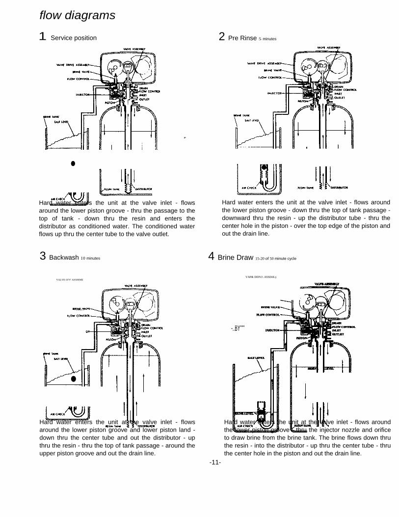
flow diagrams
1 Service position
• Hard water enters the unit at the valve inlet - flows
around the lower piston groove - thru the passage to the top of tank - down thru the resin and enters the distributor as conditioned water. The conditioned water flows up thru the center tube to the valve outlet.
3 Backwash 10 minutes
VALVE Ol'V' AS50EMll
INJECT
• Hard water enters the unit at the valve inlet - flows
around the lower piston groove and lower piston land -down thru the center tube and out the distributor - up thru the resin - thru the top of tank passage - around the upper piston groove and out the drain line.
2 Pre Rinse 5 minutes
Hard water enters the unit at the valve inlet - flows around the lower piston groove - down thru the top of tank passage - downward thru the resin - up the distributor tube - thru the center hole in the piston - over the top edge of the piston and out the drain line.
4 Brine Draw 15-20 of 50 minute cycle
VAP& DIlIVJ:.ASSDiILy
-..BY"""
Hard water enters the unit at the valve inlet - flows around the lower piston groove - thru the injector nozzle and orifice to draw brine from the brine tank. The brine flows down thru the resin - into the distributor - up thru the center tube - thru the center hole in the piston and out the drain line.
-11-

- -
flow diagrams 5 Slow rinse balance of 50 minute cycle
After all the brine has been drawn from the brine tank, hard water continues to enter thru the valve inlet - flows around the lower piston groove - thru the nozzle and orifice - down thru the resin and into the distributor - up thru the center tube - thru the center hole in the piston and out the drain line.
7 Settling rinse 5 minutes
VALVE 04UVIE MSlMIL
•• INE VAlVE
flOW CONTICM.
tNJlCTOlt
IItNf TAMIl SAlT LEY(
Hard water enters the unit at the valve inlet - flows around the lower piston groove - down thru the top of tank passage - downward thru the resin - up the distributor tube - thru the center hole in the piston -over the top edge of the piston and out the drain line.
6 Rapid rinse 10 minutes
Hard water enters the unit at the valve inlet - flows around the lower piston groove and lower piston land -down thru the center tube and out the distributor - up thru the resin - thru the top of tank passage - around the upper piston groove and out the drain line.
8 Regenerant tank refill Adjustable4-24minutes
REFILL (SALT DOSE)ADJUSMENT CAM
YAl'lf OlivE ASSEMI(
ItUIN LlVll'

Service Cleaning Iron Out of the Water Softening System The Fleet Farm Water Treatment system is designed to remove minerals like calcium and magnesium from household water. Fleet Farm Water Treatment recommends periodic resin bed cleaning if your iron rating is high. Clean the bed at least every six months, or more if iron appears in the soft water between cleanings.
Checking for a Salt Bridge A hard crust or "Salt Bridge" can form in the lower half of the salt storage tank. This can be deceiving because the tank will appear to have plenty of salt, but underneath, salt has hardened and when the system regenerates, water cannot quite reach this level to be made into brine (water and salt).
Breaking a Salt Bridge Take a wooden broom handle and carefully push it down into the salt, working it up and down. If the tool strikes a hard object (be sure it's not the bottom or sides of the tank), it's probably a salt bridge. Carefully break the bridge with the broom handle. Do not pound on the walls of the tank. NOTE: Salt bridges are typically caused by high humidity or using the wrong kind of salt. In humid areas it is best to fill with less salt, more often. Use only nugget, pellet, block, or coarse solar salt with a purity of 99.5% or higher. DO NOT granulated, and ice cream-making salts, or salt with iron-removing additives.
Cleaning the Injector and Screen 1) Turn off water supply to conditioner:
a) If the conditioner installation has a “three valve” by-pass system, first open the valve in the bypass line, and then close the valves at the conditioner inlet and outlet.
b) If the conditioner has an integral by-pass valve, put it in the by-pass position. c) If there is only a shut-off valve near the conditioner inlet, close it.
2) Relieve water pressure in the conditioner by stepping the control into the backwash position momentarily. Return the control to the service position.
3) Unplug electrical cord from outlet. 4) Disconnect brine tube and drain line connections at the injector body. 5) Remove the two injector body mounting screws. The injector and brine module can now be removed from the control
valve. Clean and reassemble. 6) To replace brine valve.
a) Pull brine valve from injector body, also remove and discard O-ring at bottom of brine valve hole. b) Apply silicone lubricant to new O-ring and reinstall at bottom of brine valve hole. c) Apply silicone lubricant to O-ring on new valve assembly and press into brine valve hole, shoulder on bushing
should be flush with injector body. 7) To replace injectors and screen.
a) Remove injector cap and screen, discard O-ring. Unscrew injector nozzle and throat. b) Screw in new injector throat and nozzle, be sure they are sealed tightly. Install a new screen. c) Apply silicone lubricant to new O-ring and install around oval extension on injector cap.
8) Apply silicone lubricant to three new O-rings and install over three bosses on injector body. 9) Insert screws with washers thru injector cap and injector. Place this assembly thru hole in timer housing and into
mating holes in the valve body. 10) Tighten screws. 11) Reconnect brine tube and drain line. 12) Return by-pass or inlet valving to normal service position. Water pressure should now be applied to the conditioner,
and any by-pass line shut off. 13) Check for leaks at all seal areas. Check drain seal with the control in the backwash position. 14) Plug electrical cord into outlet. 15) Set time of day and cycle the control valve manually to
assure proper function. Make sure control valve is returned to the service position.
16) Make sure there is enough salt in the brine tank. 17) Start regeneration cycle manually if water is hard.
Hard water enters the unit at the valve inlet -flows around the lower piston groove - thru the injector throat - thru the brine valve and flow control to fill the brine tank. Hard water also flows around the lower piston groove - thru the passage to the top of tank - down thru the resin and enters the distributor as conditioned water. The conditioned water flows up thru the center tube to the
-12- valve outlet.

Troubleshooting
1. Softener Fails To Regenerate. A. Electrical service to unit has been interrupted.
A. Assure permanent electrical service (check fuse, plug, pull chain or switch).
B. Timer programming bad (improper programming).
B. Check programming and reset as needed.
2. Softener Delivers Hard Water. A. By-pass valve is open. A. Close by-pass valve.
B. No salt in brine tank. B. Add salt to brine tank and maintain salt level above water level.
C. Injectors or screen plugged. C. Clean or replace injectors and screen. D. Insufficient water flowing into brine tank.
D. Check brine tank fill time and clean brine line flow if plugged.
E. Hot water tank hardness. E. Repeated flushings of the hot water tank is required.
F. Flow meter jammed. F. Check flow indicator light for flow. Remove obstruction from flow meter.
G. Flow meter cable disconnected or not plugged into meter.
G. Check meter cable connection to timer and meter.
H. Improper programming. H. Reprogram the control to the proper regeneration type, inlet water hardness, capacity or flow meter size.
I. Plugged brine line or air check. I. Remove and clean any sediment from brine tank and brine valve assembly.
J. Salt bridge has formed. J. Refer to Breaking a Salt Bridge section in manual.
K. No water in brine tank. K. Ensure safety float is not stuck. L. Unit is plumbed backwards. L. Check that the unit is plumbed correctly. M. Water hardness has increased or is set incorrectly.
M. Retest hardness and change settings
N. Water pressure is too low. N. Line pressure must be at least 20psi.
3. Unit Uses Too Much Salt. A. Improper salt setting. A. Check salt usage and salt setting. B. Excessive water in brine tank. B. See problem No. 7. C. Improper programming. C. Check programming and reset as needed.
4. Loss of Water Pressure. A. Iron buildup in line to water conditioner.
A. Clean line to water conditioner.
B. Iron buildup in water conditioner. B. Clean control and add resin cleaner to resin bed. Increase frequency of regeneration.
5. Loss of Resin Through Drain Line.
A. Air in water system. A. Assure that well system has proper air eliminator control and check for dry well condition.
B. Drain line flow control is too large. B. Ensure drain line flow control is sized correctly.
6. Iron in Conditioned Water. A. Fouled resin bed. A. Check backwash, brine draw and brine tank fill. Increase frequency of regeneration. Increase backwash time.
B. Iron content exceeds recommended parameters.
B. Add iron removal from filter or system.

7. Excessive Water in Brine Tank. A. Plugged drain line flow control. A. Clean flow control.
B. Brine valve failure. B. Clean brine valve. C. Improper programming. C. Check programming and reset as needed.
8. Salt Water in Service Line. A. Plugged injector system. A. Clean injector and replace screen. B. Improper programming. B. Check programming and reset as needed. C. Foreign material in brine valve. C. Clean or replace brine valve. D. Foreign material in brine line flow control.
D. Clean brine line flow control.
E. Low water pressure. E. Raise water pressure.
9. Softener Fails to Draw Brine. A. Drain line flow control is plugged. A. Clean drain line flow control. B. Injector is plugged. B. Clean or replace injectors. C. Improper programming. C. Check programming and reset as needed. D. Line pressure is too low. D. Increase line pressure (line pressure must be at
least 20psi at all times.)
10. Drain Flows Continuously. A. Foreign material in control. A. Remove piston assembly and inspect bore, remove foreign material & check control in various ports.
12. Loss of capacity. A. Increased raw water hardness A. Reset unit to the new capacity.
B. Brine concentration and/or quantity. B. Keep brine tank full of salt at all times. Clean it yearly. Salt may be bridged. If using a salt grid plate ensure refill water is over it.
C. Resin fouling. Future fouling. C. Call Fleet Farm Water Treatment, find out how to confirm it, clean the resin and prevent.
D. Poor distribution, channeling (uneven bed surface).
D. Call Fleet Farm Water Treatment. Check distributors and backwash flow.

-
meter assembly parts diagrams
by-pass valve assembly
ITEMNO. 1 2
3 4 5 6 7 8 9
NO.REQ'O 4 1 1 1 1 4 4 1 4 1
PART NO. 12473 14038 15100 13847 13009 13314 13256 13821 13305 14613
DESCRIPTION Screw - Meter Cover Assembly Meter Cover Assembly- Standard Meter Cover Assembly-Extended Range (not shown) "0" Ring - Meter Cover Assembly In1leHer Screw - Adapter Clip Adapter Clip Meter Body "0" Ring - Meter Body Row Straightener
control assembly metered water softener
@> ..• g --- ~j) __ -_7
ITEMNO. 1 2 3 4 6 7 8 9
10 11
NO. REQ'O. PART NO. 1 11969 1 11443 1 11979 8 15727 1 13604 1 11978 1 11972 1 13254 1 13399 1 11726 1 11986
DESCRIPTION Round Head Machine Screw Plain Washer Wwl..eYer Hex. Head Machine Screw WveLabel Side Cover Valve Plug Valve Body-314" N.P.T. Valve Body -1" N.P.T. Valve Seal Side Cover
rrEMNO. NO.REQ'O PART NO. DESCRIPTION 1 1 14448 Drive Housing Assembly 2 1 13175 Motor Mounting Plate 3 1 13400 Motor -1m 60Hz 1 13494 Motor - 24V 60 Hz 4 3 11384 Screw - Motor Mig & Ground Wire 5 7 13296 Screw· Component Mounting 6 1 1:D17 Idler Gear 7 1 1:D18 Idler Pinion 8 1 13312 Spring - Idler 9 1 13164 Drive Gear 10 1 13299 Curved Washer 11 1 13170 Main Gear & Shaft 12 1 1:D09 24 Hour Gear 13 1 13802 Cycle Actuator Gear 14 1 14177 Knob - Manual Regeneration 15 2 13300 Ball-Dia. 16 2 14457 Spring - Detent 17 1 13969 24 Hour Label 18 1 13748 Screw· Program Wheel 19 1 14039 Program Wheel Assembly - Specify Hardness
Capacity :ill 1 138re Program Wheel Retainer 21 1 13953 Cover LabeI- Program Wheel 22 1 11842 Beclrical CortI Zl 2 12681 Wire Connector 24 1 13547 Strain Relief 25 1 13229 Back Cover 26 Not Assigned 27 1 13955 Front LabeI- Beige
1 13958 Front Label- Silver 28 1 13899 Rear Label 29 1 13957 Tape Stripe - Beige
1 138&l Tape Stripe - Silver 3l 1 13168 Brine Cam 31 1 11980 Screw - Time Fill Cam 32 1 11081 Nut- Time Fill Cam 33 1 13169 Time RII Cam 34 2 12473 Screw - Drive Mounting 35 1 1:ill37 Washer 35 1 13:D7 Label'Lbs ri Sall- 3-18"
1 13489 Label"Lbs of Salt· 6-36" '31 1 138:D Drive Pinion - Program Wheel 38 1 13831 Clutch • Drive Pinion :Jl 1 14253 Spring Retainer 40 1 14276 Spring 41 1 14043 Flexible Cable Assembly 42 1 14176 Valve Position Dial - Standard
1 14278 Valve Position Dial - Low Water 1 15478 Valve Position Dial- Filter 43 1 14175 Knob Label- Beige
1 14207 Knob Label- Silver 44 1 15151 Screw Knob
-13-
_-1
-
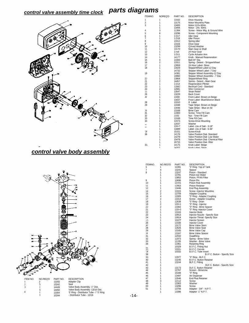
parts diagrams lTEMNO. NOREQ'D PART NO. DESCRIPTION 1 1 13162 Drive Housing 2 1 13175 Motor Mounting Plate 3 1 13400 Molor-11Ov.60Hz.
1 13494 Motor - 24v. 60Hz. 4 3 11384 Screw - Motor MIg. & Ground Wire 5 8 13296 Screw - Component Mounting 6 1 1:D17 Idler Gear 7 1 1:D18 Idler Pinion 8 1 13312 Spring-Idler 9 1 13164 Drive Gear 10 1 13299 QJrved Washer 11 1 13170 Main Gear & Shall 12 1 1:nxil 24 Hour Gear 13 1 1:D11 Cycle AcluaIor Ann 14 1 14177 Knob - Manual Regeneration 15 4 13300 BaIl-l/4" Dia. 16 2 13311 Spring - Detent - Sl<ipperWheel 17 1 13959 24 Hour LabeI- Silver 18 1 13429 SkipperWheel Label-12 Day
1 14732 Skipper Wheel LabeI- 7 Day 19 1 14381 Skipper Wheel AssembIy-12 Day
1 14860 Skipper Wheel Assembly - 7 Day 2J 1 13864 SkipperWheeI Ring 21 2 14457 Spring - Detent - Main Gear 22 1 1:D14 Regeneration Pllinter 23 1 11842 Beclrical Cord - Standard 24 2 12681 Wire Connec1cr :15 1 13547 Strain Relief 26 1 13229 Back Cover Xl 1 133)9 Front LabeI- Brown on Beige
1 13437 Froot LabeI- BluelSilveron Black 28 1 13310 R_LabeI 29 1 13348 Tape Slripe- Brown on Beige
1 13436 Tape Slripe - Blue on SiI_ 3l 1 13168 Brine Cam 31 1 11900 Screw- Time Fill Cam 32 1 11001 Nut - Time Fill Cam 33 1 13169 Time Fill Cam 34 2 12473 Screw-Drive Mounting
~ 1 12037 Washer ~ 1 133>7 Label- Lbs of Salt - 3-18"
1 13489 Label- Lbs of Salt - 6-36" '3l 1 15151 Screw-Knob 38 1 14176 Valve Position Dial- Standard
1 14278 Valve Position Dial- Low Water
1 15478 Valve Position Dial- Chemical Riter
1 16715 Valve Position DiaI- Riter 31 1 14175 Knob LabeI- Beige
1 14207 Knob LabeI- Silver
control valve assembly time clock
.----
control valve body assembly
-
ITEM NO. 1 2 3
4
NO.REQ'D 2 5 1 1 1 1
PART NO. 13255 13242 14449 14450 13304 10244
DESCRIPTION Adapter Clip Seal Valve Body Assembly -1" Dist. Valve Body Assembly -13/16 Dist. '0' Ring - Distributor Tube - l' '0' Ring - Distributor Tube - 13/16
lTEMNO. NO.REQ'D PART NO. DESCRIPTION 5 1 12281 "0' Ring- Top of Tank 7 4 13241 Spacer 8 1 13247 Piston - Standard
1 13781 Piston low Water 1 13852 Piston, FFAN Filter
9 1 10696 Piston Pin 10 1 13>01 Piston Rod Assembly 11 1 12953 Piston Retainer 12 1 13446 End Plug Assembly 14 2 13315 Screw -Injector Mounting 15 2 13709 Adapter Coupling 16 4 13305 "0' Ring - Adapter Coupling 17 2 13314 Screw - Adapter Coupling 18 1 12638 "0' Ring - Drain 19 2 133>1 "0" Ring - Injector 2J 2 13302 "0" Ring - Brine Spacer 21 1 133>3 "0" Ring -Injector Cover 22 1 13163 Injector Body 23 1 10913 Injector Nozzle - Specify Size 24 1 10914 Injector Throat -Specify Size :15 1 102ZT Injector Screen 26 1 13166 Injector Cover Xl 1 13172 Brine Valve Stem 28 1 12626 Brine Valve Seat 29 1 13165 Brine Valve Cap 3l 1 13167 Brine Valve Spacer 31 1 12550 OuadRing 32 1 11973 Spring - Brine Valve 33 1 12J35 Washer - Brine Valve 34 1 11961 Retaining Ring
~ 1 10329 B.l.F.C. Frtting Nut 33 1 1033> B.l.F.C. Ferrule '3l 1 10332 B.l.F.C. Tube Insert 38 1 B.l.F.C. Button - Specify Size 31 1 12977 "0" Ring - BLF.C. 40 1 13245 B.l.F.C. Button Retainer 41 1 13244 BLF.C, Fitting 42 1 DLF.C. Button - Specify Size 43 1 13173 DLF.C. Button Retainer 44 1 12767 Screen - BrineUne 45 1 15348 "0" Ring 46 1 13497 Air Disperser 47 1 13546 End Plug Retainer 48 3 12112 Screw 49 1 13363 Washer 00 1 13296 Screw 51 1 13706 Adapter - 3/4" - N.P.T.
1 13396 Adapter -1" N.P.T.
-14-


Fleet Farm Water Softeners Manufactured By
Water Right Inc. 1900 Prospect Ct.
Appleton WI 54914 800.777.1426 Ph. 920-739-9406 Fax