Embed Size (px)
Citation preview

Waveguides of a Composite Plate by using theSpectral Finite Element Approach
E. BARBIERIDepartment of Mechanical Engineering, University of Bath, Bath BA2 7AY, UK([email protected])
A. CAMMARANOS. DE ROSAF. FRANCOælab - Vibration and Acoustics Laboratory, Dipartimento di Ingegneria Aerospaziale, Universita’degli Studi di Napoli Federico II, 80125 Via Claudio, Napoli, Italy
Received 15 May 2007� accepted 15 October 2007
Abstract: This work presents the extension of an existing procedure for evaluating the waveguides and thedispersion curves of a laminate made up of thin orthotropic composite plates arbitrarily oriented. The adoptedapproach is based on one-dimensional finite-element mesh throughout the thickness. Stiffness and mass ma-trices available in the literature for isotropic material are reported in full expanded form for the selectedproblem. The aim of the work is the development of a tool for the simulation of the most common compositematerials. The knowledge of the wave characteristics in a plate allows correct sizing of the numerical meshfor the frequency-dependent analysis. The development of new stiffness matrices and the analysis for dif-ferent heading angles are detailed to take into account the general anisotropic nature of the composite. Theprocedure concerns a standard polynomial eigenvalue problem in the wavenumber variable and is focused onthe evaluation of the dispersion curves for all the propagating waves within the materials. A comparison withan analytical approach is also shown in the results using the classical laminate plate theory (CLPT). How-ever, limits of CLPT are outlined and spectral finite element method can be successfully used to overcomesuch limitations.
Keywords: waveguides, dispersion, composite plate, wavenumber, modal density.
1. INTRODUCTION AND STATEMENT OF THE PROBLEM
The wide and increasing use of innovative materials in transportation engineering is oneof the most fascinating challenges of material science. In the aerospace field, this chal-lenge can be defined as always being open since manufacturers are continuously looking forstiffer, robust, long-life and lighter structural components. The need for such material per-formance has driven for a long time the focus on fiber-reinforced composite materials andnow they are a standard in several fields of transportation engineering design. One of themain problems of these innovative materials is their vibroacoustic behavior, since sometimes
Journal of Vibration and Control, 00(0): 1–21, 2009 DOI: 10.1177/1077546307087455
��2009 SAGE Publications Los Angeles, London, New Delhi, Singapore
Journal of Vibration and Control OnlineFirst, published on January 12, 2009 as doi:10.1177/1077546307087455

2 E. BARBIERI ET AL.
the lightness requirement is in conflict with the acoustic target. Hence, in the design phasethere is the need to simulate the dynamic behavior of innovative materials. This target canbe obtained by using deterministic methods (Cook et al., 1989) and also energy methods(Lyon, 1975). The deterministic techniques, such as finite-element analysis (FEA), work bydiscretizing the given wavelength. In principle, they can be used for evaluating the responseat any excitation frequency, but the computational cost (CPU time) can become easily unac-ceptable. In the absence of any analytical development, the deterministic techniques modeldirectly the wavelength, by assigning at least five solution points (four elements) for eachcomplete wave (Cook et al., 1989� Cremer et al., 2005). For increasing excitation frequency,the response becomes global, that is any quadratic mean can represent the overall behavior,and the possibility to discriminate the dynamic response among different points in space islost. The best technique working under these conditions is the well-known statistical en-ergy analysis (SEA) (Lyon, 1975). In Ghinet et al. (2005), for example, a SEA methodfor the transmission loss of sandwich shells is illustrated, in which the dispersion propertiesof laminates are exploited. Finnveden (2004) studied the waveguides in thin-walled struc-tures with a finite-element formulation in order to compute group velocity and modal densityas input to a SEA model. Wave propagation in laminated composite plates and rods (Baz,2000) has been treated in depth by numerous authors in the past. Datta et al. (1988) haveapplied a stiffness method for a laminate made of transversely isotropic laminae, while inNayfeh (1991) dispersion curves for anisotropic laminates are analytically extracted by themeans of the transfer matrix method. A similar method can be found in Wang and Yuan(2007) for the evaluation of the group velocities and their applications in non-destructivetechniques. Chitnis et al. (2001) used a higher-order theory displacement based formula-tion. In-plane elastic waves in a composite panel are investigated in �Zak et al. (2006) witha spectral finite-element approach in the time domain. Birgersson et al. (2004) also used aspectral approach for modelling turbulence-induced vibration in pipes. In FEA, the knowl-edge of the wavelength is absolutely mandatory for proceeding with the mesh sizing and forselecting the proper elements� in SEA, detailed information about the group velocity andthe modal density are necessary for the characterization of the specific subsystem and forlater moving to analyze the energy exchange through a wave approach. The wavenumberfunction versus the excitation frequency (dispersion curves) for each structural wave con-tains the subsystem properties. Shorter (2004) and Mace et al. (2005) stressed this pointwith great attention. Shorter (2004) proposed an efficient approach for simulating an infiniteflat plate, in which a low-cost one-dimensional finite element was used for simulating thepropagating waves inside the materials. Furthermore, Mace et al. (2005) proposed the di-rect use of a finite-element model assembled to evaluate the modal response to obtain thedispersion curves. Two-dimensional approaches are also present in the literature (Johnsonand Kienholz, 1982) and the work by Heron (2002) has to be considered as one of the firstaddressing the problem of the dynamic response of a generic laminate. An extensive analysisof the related literature is reported in Shorter (2004). Nevertheless, it is worth mentioningthe applications of spectral finite elements in wave propagation for laminates, see for exam-ple Roy Mahapatra and Gopalakrishnan (2003), Mahapatra et al. (2006) and Chakrabortyand Gopalakrishnan (2006) in the frequency domain, whereas a time-domain-based spec-tral element with high-order shape functions are used in Kudela et al. (2007). The presentwork is a straight extension of the approach proposed by Shorter (2004). A one-dimensionalfinite-element model is developed for a generic plate made by a laminate composite. The

COMPOSITE PLATE BY USING THE SPECTRAL FINITE ELEMENT APPROACH 3
approach in Shorter (2004) assumes an isotropic stress–strain relationship through the use oftwo independent variables for each material.
In the present work the proper stiffness and mass matrices are developed for each lam-ina introducing a local reference system, and the whole laminate is assembled in a globalreference system. At that point a spectral finite element approach (SFEA) is used (Shorter,2004� Mace et al., 2005). The spectral term refers to the fact that the method is based onthe wavenumber at a given excitation frequency rather than the classical analysis of naturalfrequencies. The SFEA used here is the same as that presented in Shorter (2004): a full 3Ddisplacement field within the laminate with 1D elements. In the present development, a 3Dorthotropic stress–strain relationship is used (Jones, 1999), together with the proper transfor-mation from the local reference system (lamina) to the global one (laminate). The problemfor a homogeneous, isotropic plate is given in Section 2. While the dispersion properties ofa homogeneous plate are independent of the heading angle �, for a generic composite platethis is not true because of its anisotropic nature. Indeed, in a 2D orthotropic material, forexample, the principal directions of elasticity being x and y, with Ex �� Ey , the wavenum-ber at a fixed frequency changes with the angle from x to y according to an elliptic pattern.Then if an isotropic plate is considered that pattern is circular. In Section 3 an analytic for-mulation for a thin composite plate is derived, following the assumptions of the classicallaminate plate theory (CLPT) (Jones, 1999). A displacements 3D free wave is then imposedon the thin plate leading to a polynomial eigenvalue problem in k where k is the wavenumber.Bending, shear and longitudinal waves can be easily identified from the resulting equations.Furthermore, a spectral finite-element method (SFEM) will be used to obtain the dispersioncurves for a generic composite plate and then compared to the analytical approach. Theseresults are shown in Section 6 in the form of polar patterns at fixed frequency and spectra atfixed heading angle. Section 4 is devoted to the overall development of the required SFEMmatrices. Section 5 is centered on the solution of the characteristic equation, and the resultsare presented in Section 6. These results are for both a homogeneous and a composite plate.The work is concluded in Section 7 where some considerations are given about the valid-ity of the CLPT. It is demonstrated how the present numerical method can work with anyconfiguration, overcoming the limitations of the standard theoretical models.
2. THE HOMOGENEOUS PLATE
A uniform thin and flat plate is considered, made of a homogeneous material. From classicalthin plate theory (Leissa, 1993) it is well known that three waves will propagate in the mate-rial of thickness h: longitudinal, shear and bending waves. Each of these is associated withthe respective wavenumber kl , ks and kb:
k2l �
�1� �2��
E�2� k2
s �2�1� ���
E�2� k4
b �12�1� �2��
Eh2�2� (1)
In Equation (1) the longitudinal wave speed Cl���2 � E
��1��2�, the shear wave speed Cs���
2 �E
2��1��� and the plate bending stiffness D � Eh2
12��1��2�. The generic group velocity and the
wavelength for each wave can be defined by using the definition

4 E. BARBIERI ET AL.
Cg � �
kg� � Cg
f(2)
and the modal density for a plate of area A (Lyon, 1975)
ng��� � A
2�2
k���
cg���� (3)
By using these relationships, any information for a predictive methodology, deterministic orenergetic, can be obtained. In fact, the mesh of the predictive finite-element model could bedesigned to work up to a given excitation frequency. The model will be completed with thespecific boundary conditions. For the energy methods all is known about the plate, for a givenmaterial and dimensions. Both the predictive models have to be completed including thedamping information. In the following sections, a SFEM will be used to find the dispersioncurves for a generic composite plate and the results will be compared to those obtained fromthe analytical approach.
3. ANALYTICAL STRUCTURAL WAVEGUIDES FOR A THIN
COMPOSITE PLATE
According to the assumptions of the classical thin plate theory, in a plane stress problem thefollowing equations of equilibrium can be written (Timoshenko and Goodier, 1970):
Nx
x� Nxy
y� �s �u � 0� (4)
Nxy
x� Ny
y� �s �� � 0� (5)
2 Mx
x2�
2 My
y2� 2
2 Mxy
xy� �s � � 0� (6)
where Nx , Ny and Nxy are shearing forces per unit length, Mx , My are the bending momentsper unit length and Mxy the twisting moments per unit length, while �s is the surface massdensity. For a composite plate, the following relationships between force, moment and straincurvatures can be established (Jones, 1999):
N � A��0 � B�� (7)
M � B��0 �D�� (8)
where ��0 are the strains of the middle plane,

COMPOSITE PLATE BY USING THE SPECTRAL FINITE ELEMENT APPROACH 5
��0 �
�����x
� y
�xy
���� ����������
u
x
�
y
u
y� �
x
���������(9)
and � are the curvatures of the middle plane,
� �
����� x
� y
� xy
���� �����������
�2
x2
�2
y2
�22
xy
����������� (10)
The following 3D displacement wave is assumed to propagate along the plate:����u�x� y� t�
��x� y� t�
�x� y� t�
���� �����
U
V
W
���� e j[k�cos���x�sin���y���t]� (11)
where � is the heading angle of the wave, u, � and are respectively the displacement fieldsin the x , y and z axes, and U , V and W are the respective magnitudes of the propagatingwave. Substituting Equations (7)–(10) into (4)–(6) and with the assumed displacement field(11), the following polynomial eigenproblem in k is obtained:
� �k2LT AL� jk3LT BP
� jk3PT BL� �k4PT DP
�����U
V
W
����� �s�2I
����U
V
W
���� � 0� (12)
where
L �
����cos��� 0
0 sin���
sin��� cos���
���� � (13)
PT � cos2��� sin2��� 2 sin��� cos���� (14)

6 E. BARBIERI ET AL.
If a symmetric laminate is considered, then B � 0 and the polynomial problem (12) can bede-coupled into the following two eigenproblems:
�k2LT AL�
UV
�� �s�
2I�
UV
�� 0� (15)
�k4PT DP W � �s�2W � 0� (16)
It can be seen from Equation (15) that, being coupled shear-longitudinal waves, k � � whilefrom Equation(16) for the flexural wave it follows that k � ��. Indeed, from Equation (16)it can be directly derived that the flexural wavenumber is
k f ����� � 4
�s
PT DP
��� (17)
For Equation (15), if � l and � s are the two eigenvalues of the matrix LT AL, then
ks��� �� �
�s
� s����� ke��� �� �
�s
� e����� (18)
Using Equation (2), the group velocities can easily be evaluated:
C f � 2 4
�PT DP�s
��� Cs �
�� s���
�s
� Ce ��� e���
�s
� (19)
4. ASSEMBLY OF MATRICES
4.1. Variational Formulation
With the intent of establishing a finite-element model, Hamilton’s principle is used,
�
���T �U�dt
�� 0� (20)
where T is the kinetic energy and U is the strain energy. If a time average over a period isconsidered, then
T � 1
2
��
dH � d d�� (21)
where d is the displacements field, � is the mass density and the superscript H means her-mitian,

COMPOSITE PLATE BY USING THE SPECTRAL FINITE ELEMENT APPROACH 7
Figure 1. 1D mesh.
U � 1
2
��
eH s d� � 1
2
��
eH Cx�y e d�� (22)
where e is the vectorized strain tensor and s is the vectorized stress tensor in the laminatereference system, Cx�y is the stress–strain relationship matrix in the laminate reference and� is the space domain made of a single element of length L and an arbitrary rectangulardomain in the plane x–y.
4.2. Finite-element Displacement Fields
Assuming that x is the direction of the propagating wave (Figure 1) with frequency �, thewavenumber is k and the heading angle is �, the displacement field can be approximated as
d�x� y� z� t� �
����u�z�
��z�
�z�
���� e j[�t�k�cos���x�sin���y�]� (23)
Equation (23) resembles Equation (11), with the only exception being that in Equation (11)the displacements refer to a plane stress problem, while in Equation (23) a full 3D stress–strain problem is considered. The displacements at x � 0 for the single element of length Lcan be approximated by the following one-dimensional interpolating function:

8 E. BARBIERI ET AL.
����u�z�
��z�
�z�
���� �����
Ni�z� 0 0
0 Ni�z� 0
0 0 Ni�z�
��������
qu
q�
q
���� � N�z� � q0� (24)
with N�z� the matrix of shape functions (size 3�6) and q0 the vector of complex amplitudesof nodal displacements (Cook et al., 1989)
Ni�z� ��
1� z
L
z
L
�� (25)
����qu
q�
q
���� �
��������������
u1
u2
�1
�2
1
2
��������������� (26)
4.3. Def inition of Stiffness and Mass Matrices
The strain in the element is
e�x� y� z� t� �
��������������
�xx
� yy
�zz
� yz
� xz
� xy
���������������
������������������������
x0 0
0
y0
0 0
z
y
x0
z0
x
0
z
y
������������������������
d� (27)
By using Equation (23),
e�x� y� z� t� � F�k� �� z� � q0e j[�t�k�cos���x�sin���y�]� (28)

COMPOSITE PLATE BY USING THE SPECTRAL FINITE ELEMENT APPROACH 9
where the strain-displacement matrix F�k� �� z� (size 6� 6) is given by
F�k� �� z� �
�������������������
� jk cos���Ni�z� 0 0
0 � jk sin���Ni�z� 0
0 0Ni
z
0Ni
z� jk sin���Ni�z�
Ni
z0 � jk cos���Ni�z�
� jk sin���Ni�z� � jk cos���Ni�z� 0
�������������������
� (29)
Now it is necessary to introduce a stress–strain relationship for a 3D orthotropic materialin the lamina reference OxL yL . For this kind of material, nine independent engineeringconstants are needed (Jones, 1999):
sL � CL � eL� CL � S�1L � (30)
SL �
������������������������
1
E11
��21
E22
��31
E330 0 0
��12
E11
1
E22
��32
E330 0 0
��13
E11
��23
E22
1
E330 0 0
0 0 01
G230 0
0 0 0 01
G310
0 0 0 0 01
G12
������������������������
� (31)
where the matrix is symmetric from Betti’s theorem (Jones, 1999),
�i j
Eii� � j i
E j j� i� j � 1� 2� 3� (32)
Then the following tensorial reference transformation between lamina reference andlaminate reference Oxy is introduced (Figure 2):
Cx�y � T����1CLRT���R�1� (33)

10 E. BARBIERI ET AL.
Figure 2. Reference transformation between lamina reference OxL yL and laminate reference Oxy.
where � is the angle between the xL–yL axis and the x–y axis (the z-axis is the same for bothreferences),
T��� ���������������
cos2��� sin2��� 0 0 0 2 sin��� cos���
sin2��� cos2��� 0 0 0 �2 sin��� cos���
0 0 1 0 0 0
0 0 0 cos��� � sin��� 0
0 0 0 sin��� cos��� 0
� sin��� cos��� sin��� cos��� 0 0 0 cos2���� sin2���
��������������� (34)
and
R �
��������������
1 0 0 0 0 0
0 1 0 0 0 0
0 0 1 0 0 0
0 0 0 2 0 0
0 0 0 0 2 0
0 0 0 0 0 2
��������������� (35)
Then the time-averaged kinetic and strain energies can be evaluated as

COMPOSITE PLATE BY USING THE SPECTRAL FINITE ELEMENT APPROACH 11
T � �1
2�2qH
0
���
N�z�T�N�z�d��
q0� (36)
U � 1
2qH
0
���
F�k� �� z�H Cx�yF�k� �� z�d�
�q0� (37)
Substituting Equations (36) and (37) into Equation (20), we have
�
���
2
2qT
0 Mq0 � 1
2qT
0 K�k� ��q0
�� 0� (38)
where the mass and stiffness matrices are defined as
M �� L
0N�z�T�N�z�dz� (39)
and
K�k� �� �� L
0FH �k� �� z�Cx�yF�k� �� z�dz� (40)
where L is the length of the element. Furthermore, Equation (40) returns the case of auniform and isotropic plate if � � 0, E11 � E22 � E33 � E , �12 � �31 � �23 � � andG12 � G31 � G23 � E
2�1��� . Since the strain-displacement matrix only contains terms linearin k, the stiffness matrix can be rewritten in the form
K�k� �� � K2���k2 �K1���k �K0���� (41)
A single element has six degrees of freedom. The number of eigenvalues that could beextracted from such an element is then six, which is the exact number of the propagatingwaves (three for both directions of travel). Moreover, even only one element can give goodresults for the dispersive relations in a homogeneous plate, as will be shown below. Thena rule of thumb for discretizing the thickness could be one or two elements per layer ofthe laminate. As the proposed mesh is a 1D discretization, all these matrices can easily beassembled in a straightforward way. Indeed, given the elastic properties of each layer, thematrices K0, K1, K2 and M are readily calculated. Afterwards, these matrices are expandedto the size of the total number of nodes, allocated in the right position and then they are allsummed in order to give the assembled matrices of the whole thickness.
5. CHARACTERISTIC EQUATION AND OUTPUT FEATURES
Using the above variational formulation, from Equation (38),
�qT0
��2Mq0 �K�k� ��q0
� 0 �q0� (42)

12 E. BARBIERI ET AL.
and thus the characteristic equation takes the following form:
[K2���k2 �K1���k �K0���� �2M]q0 � 0� (43)
If � and � are fixed, the characteristic equation is a generalized quadratic eigenvalue problemfor k and the dispersion curves result in varying frequency, while at fixed � the polar patternis derived when the heading angle is in the range between 0� and 360�. This kind of problemcan be easily transformed into a linear one by the positions
q1 � kq0� (44)
C2 � K2� C1 � K1� C0 � K0 � �2M� (45)
so that �0 I
�C�12 C0 �C�1
2 C1
��q0
q1
�� k
�I 0
0 I
��q0
q1
�� 0� (46)
These eigenvalues can be divided in three groups:
(i) purely real�(ii) purely imaginary�
(iii) complex.
The eigenvalues in (i) are referred to as propagating oscillating waves, because fromEquation (23) they generate terms with no exponential decay. The waves that exhibit anexponential decay are named evanescent waves and they are of two types, non-oscillating(eigenvalues purely imaginary) and oscillating (complex eigenvalues). Evanescent waves areof no interest because they do not propagate along the material, but simply extinguish withtime. The sign of the real and imaginary parts of the eigenvalues indicate the direction oftravel of a given wave. The eigenvectors represent the cross-sectional wave shape associatedwith a given wave, at a fixed frequency. It should be noted that the eigenvectors refer to a 1Ddomain along the z-axis.
6. RESULTS
6.1. Dispersion Curves and Eigenvector Plots
6.1.1. Homogeneous Plate
In this section the consistency with the isotropic case is shown together with a comparisonwith the analytical formulas (1) for an aluminium plate of thickness 0.0012 m, density 2700kg m�3, E � 71� 109 Pa and � � 0�3296.
As it can be seen from Figures (3) and (4), there is a perfect agreement with the analyticalresults for both spectra and polar patterns, even if only two linear elements are used� the
COMPOSITE PLATE BY USING THE SPECTRAL FINITE ELEMENT APPROACH 13
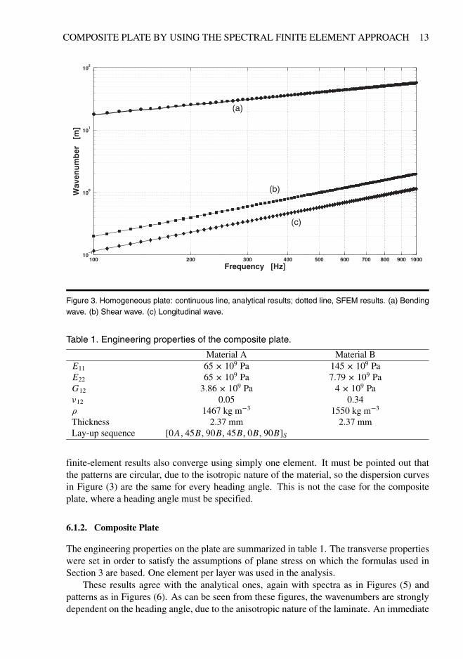
Figure 3. Homogeneous plate: continuous line, analytical results� dotted line, SFEM results. (a) Bendingwave. (b) Shear wave. (c) Longitudinal wave.
Table 1. Engineering properties of the composite plate.
Material A Material BE11 65� 109 Pa 145� 109 PaE22 65� 109 Pa 7�79� 109 PaG12 3�86� 109 Pa 4� 109 Pa�12 0.05 0.34� 1467 kg m�3 1550 kg m�3
Thickness 2.37 mm 2.37 mmLay-up sequence [0A� 45B� 90B� 45B� 0B� 90B]S
finite-element results also converge using simply one element. It must be pointed out thatthe patterns are circular, due to the isotropic nature of the material, so the dispersion curvesin Figure (3) are the same for every heading angle. This is not the case for the compositeplate, where a heading angle must be specified.
6.1.2. Composite Plate
The engineering properties on the plate are summarized in table 1. The transverse propertieswere set in order to satisfy the assumptions of plane stress on which the formulas used inSection 3 are based. One element per layer was used in the analysis.
These results agree with the analytical ones, again with spectra as in Figures (5) andpatterns as in Figures (6). As can be seen from these figures, the wavenumbers are stronglydependent on the heading angle, due to the anisotropic nature of the laminate. An immediate

14 E. BARBIERI ET AL.
Figure 4. Polar patterns for the homogeneous plate: continuous line: analytical results� diamonds: SFEMresults.
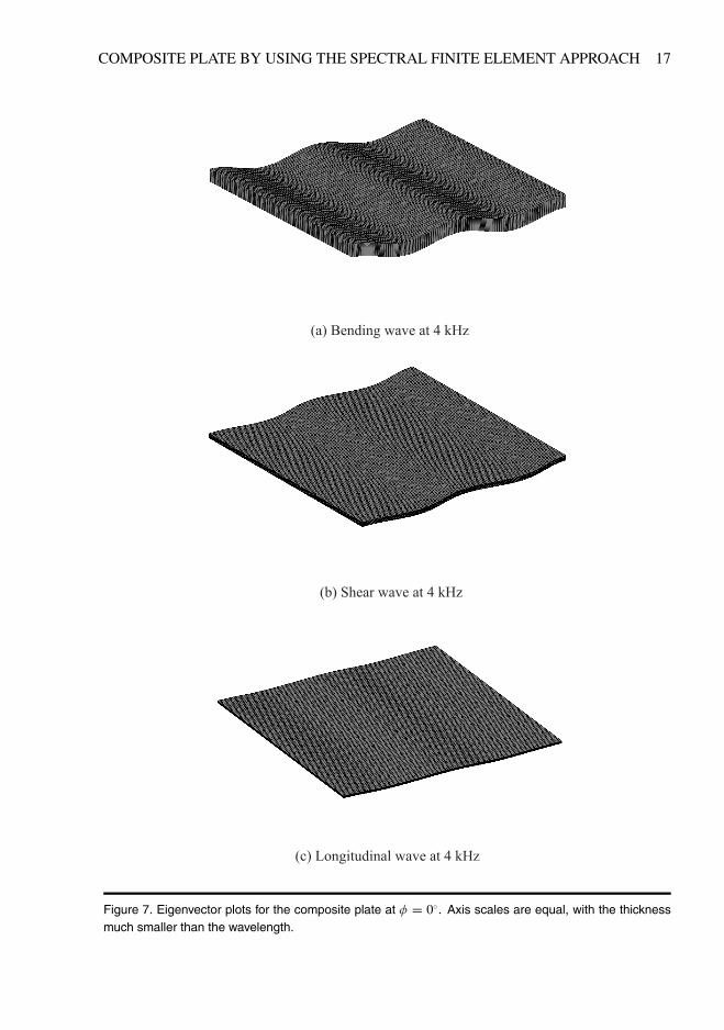
visualization of the wave as in Figures 7, (a) and (b) can be provided once the eigenvectorq0 is obtained. Then, the displacement field can be obtained from Equation (23) and thenplotted over a 3D domain in the x , y and z axes. Since the domain is finite only in the zdirection, the x and y limits of the domain can be chosen arbitrarily. The wave depictedin Figure 7 is a bending wave, whereas that depicted in Figure 7(b) is a shear wave andin Figure 7(c) a longitudinal wave is shown. Using Equation (2) the group velocity canbe evaluated from the dispersion curves. Furthermore, when area A of the rectangular flatplate is specified, from Equation (3) the modal density curves for the propagating waves canbe computed. According to a SEA formulation, these modal densities need to be averagedover the heading angle (Ghinet et al., 2005). Moreover, following (Shorter, 2004) it is also

COMPOSITE PLATE BY USING THE SPECTRAL FINITE ELEMENT APPROACH 15
Figure 5. Dispersion curves for the composite plate: continuous line, analytical results� symbols, SFEMresults. (f) flexural, (s) shear, (l) longitudinal.

16 E. BARBIERI ET AL.
Figure 6. Polar patterns for the composite plate: continuous line, analytical results� diamonds: SFEMresults.
possible to evaluate the structural damping loss factor (DLF) when a DLF for each lamina isspecified. However, these details are not given here.
7. LIMITS OF CLASSICAL LAMINATE PLATE THEORY
In this section the limits of the CLPT are illustrated. For this purpose, a characteristic adi-mensional number could be introduced,
COMPOSITE PLATE BY USING THE SPECTRAL FINITE ELEMENT APPROACH 17
Figure 7. Eigenvector plots for the composite plate at � � 0�. Axis scales are equal, with the thicknessmuch smaller than the wavelength.

18 E. BARBIERI ET AL.
Figure 8. Dispersion curves for the composite plate: continuous Line, SFEM results� dash-dotted line,analytical results. (s) shear, (l) longitudinal, (a) and (b) new waveforms.
� � h
� (47)
where h is the thickness of the plate and is the smallest wavelength (usually the flexuralone). When � � 1 the plate could be considered thin, since h is much smaller than thecharacteristic length of the problem, which is the wavelength of the propagating wave. Since decreases with increase in frequency, at relatively high frequencies the analytical approachexplained in Section 3 is inadequate to predict the dispersion properties of the laminate plate,because the smallest wavelength is the same order of magnitude as the thickness. The plateindeed becomes thick. The frequency limit when such an event occurs, �lim , is when� � 1,
k��lim� � 2�
h� (48)
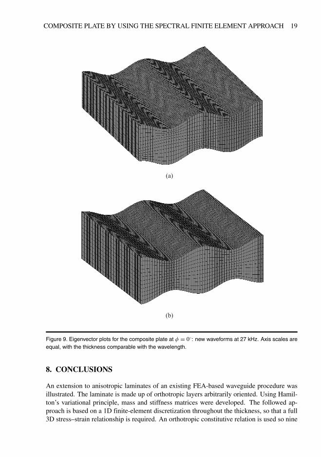
New waveforms appear when � � �lim as can be seen from the dispersion plot in Figure 7and from Figures 9. The bending wave in Figure 9(a) is slightly different from that in Figure 7and its dispersion curve differs from the analytical theory. The wave 9(b) cannot be predictedfrom the CLPT since, according to the eigenproblem (12), only six eigenvalues (three forboth directions of travel) are obtainable, whereas eight eigenvalues come from the SFEMabove 17 kHz. Thus, when the frequency increases, a SFEM approach is useful to overcomethe limits of the CLPT.
COMPOSITE PLATE BY USING THE SPECTRAL FINITE ELEMENT APPROACH 19
Figure 9. Eigenvector plots for the composite plate at � � 0�: new waveforms at 27 kHz. Axis scales areequal, with the thickness comparable with the wavelength.
8. CONCLUSIONS
An extension to anisotropic laminates of an existing FEA-based waveguide procedure wasillustrated. The laminate is made up of orthotropic layers arbitrarily oriented. Using Hamil-ton’s variational principle, mass and stiffness matrices were developed. The followed ap-proach is based on a 1D finite-element discretization throughout the thickness, so that a full3D stress–strain relationship is required. An orthotropic constitutive relation is used so nine

20 E. BARBIERI ET AL.
independent variables are needed. A reference transformation between lamina and laminatewas also necessary in order to introduce the lamina orientation. The resulting equation isexpressed in terms of a quadratic eigenproblem in the wavenumber variable at a fixed fre-quency and heading angle. This problem was transformed into a linear problem and easilysolved with standard numerical routines. Dispersion curves and polar patterns are obtainedfor the case of a uniform isotropic plate and for a laminate composite plate. Comparison withanalytical formulas available from the CLPT showed good agreement with the finite-elementresults. Nevertheless, the analytical theory fails with increase in frequency. In fact, CLPTcannot predict the appearance of new waveforms, whereas the SFEM can identify new struc-tural waveguides. Thus the SFEM can overcome the limits of the CLPT, allowing a moresatisfactory analysis of the dispersion properties at higher frequencies. The procedure can beeasily completed by including the evaluation of the resulting loss factor, given the individualloss factor of each lamina and the group velocity curves of the propagating waves, as wellas their modal densities. All the present evaluations and results have been obtained by usingMatlab: the m-files can be requested from the first author.
REFERENCES
Baz, A., 2000, “Spectral finite-element modeling of the longitudinal wave propagation in rods treated with activeconstrained layer damping,” Smart Materials and Structures 9, 372–377.
Birgersson, F., Finnveden, S., and Robert, G., 2004, “Modelling turbulence-induced vibration of pipes with aspectral finite element method,” Journal of Sound and Vibration 278(4–5), 749–772.
Chakraborty, A. and Gopalakrishnan, S., 2006, “A spectral finite element model for wave propagation analysis inlaminated composite plate,” Journal of Vibration and Acoustics 128, 477.
Chitnis, M., Desai, Y., and Kant, T., 2001, “Wave propagation in laminated composite plates using higher ordertheory,” Journal of Applied Mechanics 68(3), 503–505.
Cook, R., Malkus, D., Plesha, M., and Witt, R., 1989, Concepts and Applications of Finite Element Analysis, Wiley,New York.
Cremer, L., Petersson, B., and Heckl, M., 2005, Structure-Borne Sound: Structural Vibrations and Sound Radiationat Audio Frequencies, Springer, Berlin.
Datta, S., Shah, A., Bratton, R., and Chakraborty, T., 1988, “Wave propagation in laminated composite plates,” TheJournal of the Acoustical Society of America 83, 2020.
Finnveden, S., 2004, “Evaluation of modal density and group velocity by a finite element method,” Journal of Soundand Vibration 273(1), 51–75.
Ghinet, S., Atalla, N., and Osman, H., 2005, “The transmission loss of curved laminates and sandwich compositepanels,” The Journal of the Acoustical Society of America 118, 774.
Heron, K., 2002, “Predictive SEA and anisotropic panels,” in Proceedings of the ISMA International Conference onSound and Vibration, Leuven, Belgium, September.
Johnson, C. and Kienholz, D., 1982, “Finite element prediction of damping in structures with constrained viscoelas-tic layers,” AIAA Journal 20(9), 1284–1290.
Jones, R., 1999, Mechanics of Composite Materials, Taylor & Francis, Philadelphia.Kudela, P., �Zak, A., Krawczuk, M., and Ostachowicz, W., 2007, “Modelling of wave propagation in composite
plates using the time domain spectral element method,” Journal of Sound and Vibration 302(4–5), 728–745.Wang, L. and Yuan, F. G., 2007, “Group velocity and characteristic wave curves of Lamb waves in composites:
Modeling and experiments,” Composites Science and Technology 67, 1370–1384.Leissa, A., 1993, Vibration of Plates, Published for the Acoustical Society of America through the American Insti-
tute of Physics, New York.Lyon, R., 1975, Statistical Energy Analysis of Dynamical Systems: Theory and Applications, MIT Press, Cambridge,
MA.Mace, B., Duhamel, D., Brennan, M., and Hinke, L., 2005, “Finite element prediction of wave motion in structural
waveguides,” The Journal of the Acoustical Society of America 117, 2835.

COMPOSITE PLATE BY USING THE SPECTRAL FINITE ELEMENT APPROACH 21
Mahapatra, D., Singhal, A., and Gopalakrishnan, S., 2006, “A higher-order finite waveguide model for spectralanalysis of composite structures,” Computer Methods in Applied Mechanics and Engineering 195(9&12),1116–1135.
Nayfeh, A., 1991, “The general problem of elastic wave propagation in multilayered anisotropic media,” The Jour-nal of the Acoustical Society of America 89, 1521.
Roy Mahapatra, D. and Gopalakrishnan, S., 2003, “A spectral finite element model for analysis of axial–flexural–shear coupled wave propagation in laminated composite beams,” Composite Structures 59(1), 67–88.
Shorter, P., 2004, “Wave propagation and damping in linear viscoelastic laminates,” The Journal of the AcousticalSociety of America 115, 1917.
Timoshenko, S. and Goodier, J., 1970, Theory of Elasticity [M], MacGraw Hill, New York, pp. 328–333.�Zak, A., Krawczuk, M., and Ostachowicz, W., 2006, “Propagation of in-plane elastic waves in a composite panel,”
Finite Elements in Analysis and Design 43(2), 145–154.