Embed Size (px)
Citation preview
A New Fault Detection Tool for Single Phasing of a
Three Phase Induction Motor
S.H.Haggag, Ali M. El-Rifaie,and Hala M. Abdel Mageed
Abstract-This paper introduces a new tool for fault detection
in high voltage electrical networks; the new tool can be used by
high speed digital relays to detect fault presence besides
selecting the faulted phase(s). The suggested tool uses a new
technique that squares both of the instantaneous voltage signal
and its complement to produce a unity relation in normal
operating conditions. The unity relation will remain
undistorted as long as the power system is operating normally;
however, the unity relation will change with any sudden change
in the voltage signals due to any abnormal conditions. The
suggested tool is being applied to detect the single phasing case
for a three phase, high voltage induction motor. The simulation
was done using Matlab simulink, where the simulation results
showed great success of the suggested tool in detecting the
single phasing case for all loading conditions. The new
technique is then practically applied on a three phase induction
motor, where the single phasing case is successfully detected.
The practical results showed compliance with the simulink
results in distinguishing the single phasing fault.
Index Terms -Induction motors, Single Phasing, Digital relays
I. INTRODUCTION
A three-phase induction motor operating in the steady-
state will continue to operate when a disturbance on the
system causes the terminal voltages to become single
phased. This condition is referred to as “single phasing” and
will result in an operating condition that produces excess
heating in the motor. Such a condition requires that the
motor be provided with protection that will disconnect it
from the system before the motor is permanently damaged.
Single phasing in three phase induction motors can occur as
a result of a fuse blowing or a protective device opening on
one phase of the motor. Other possibilities include feeder or
step-down transformer fuses blowing. Even though the
motor will continue to operate in this condition, the motor
will heat up very quickly, and it is essential that the motor
be removed from service by the opening of a motor circuit
breaker or some other types of protective devices [1,2].
When one phase opens, the current to a motor in the two
remaining phases theoretically increases to 1.73 (173%)
times the normal current draw of the motor. The increase
can be as much as 2 times (200%) because of power factor
changes. Where the motor has a high inertia load, the
current can approach locked rotor values under single-
phased conditions
Manuscript received February 04, 2013; revised February 21, 2013
Ali Mohamed El-Rifaie is with the High Voltage Department at the
National Institute for Standards, Giza, Egypt. P.O.136, Code 12211 e-mail: alisystem11@ yahoo.com.
Hala Mohamed Abd Elmageed is with the Electrical Quantities Department
at the National Institute for Standards, Giza, Egypt. P.O.136, Code 12211
e-mail: halaabdelmegeed@ yahoo.com.
Three properly sized time-delay, dual-element fuses,
and/or three properly sized overload devices will sense and
respond to this overcurrent [3]. Methods for prediction and
detection of motor faults are extensively documented in the
research literature; many of these methods use stator
currents and voltage signals in some form along with
signature algorithms to determine or predict fault conditions
in an induction motor [4]. Wavelet signal processing, and
Fourier analysis are two techniques that can
be used to discriminate the single phasing case from other
voltage unbalance cases [5].
In this paper, a new fault detection tool that uses the
square value of the instantaneous voltage signal and its
complement to produce a unity relation in normal conditions
is introduced. The suggested Cos-Sin tool [6] is being
applied to detect the case of single phasing (open of one
phase) in large induction motors where Matlab simulink is
used to simulate a 2.3 KV, 2250 Hp three phase induction
motor, the simulation results showed the capability of the
suggested tool to detect the case of single phasing, relying
on the motor's voltage signal during single phasing. A
practical application of the Cos-Sin tool is also shown using
Lab View, where the Single phasing case is practically
simulated and successfully detected.
II. THE COS-SIN ALGORITHM
The Cos-Sin algorithm is given as follows: the voltage
signal at any instant for a given bus-bar is represented by
V(t) where:
(1) Ø) cos(wt V V(t) max
On the other hand the complement of this signal could be
obtained as V0(t) where:
(2) Ø) sin(wt V (t)V max0
By squaring, adding and normalizing the above two
equations, a discrimination signal SCS(t) can then be
introduced as follows:
2
max
2
0
2
max
2
CS
)()((t)S
V
tV
V
tV
(3) 1.0 Ø)Sin²(wtØ)Cos²(wt (t)SCS
The value of SCS (t) is unity as long as there is no effective
change in the value of Vmax and no extra-ordinary condition
taking place. This unity relation is distorted as soon as a
fault occurs. The peak voltage value is updated every one
complete cycle (20 msec for f=50 Hz), where full
synchronization is done between the actual voltage signal
V(t) and its complement V0(t) by acquiring the utilized
values at the same instant. Fig. 1 shows V(t) with some
disturbances due to a fault at peak voltage, while its
complement signal V0(t) appears to depend only on the pre-
Proceedings of the World Congress on Engineering 2013 Vol II, WCE 2013, July 3 - 5, 2013, London, U.K.
ISBN: 978-988-19252-8-2 ISSN: 2078-0958 (Print); ISSN: 2078-0966 (Online)
WCE 2013
fault peak voltage. Fig. 2 shows SCS(t) during normal
operation, where the unity relation is kept steady.
III. SIMULATION STUDY FOR SINGLE PHASING IN THREE
PHASE INDUCTION MOTORS
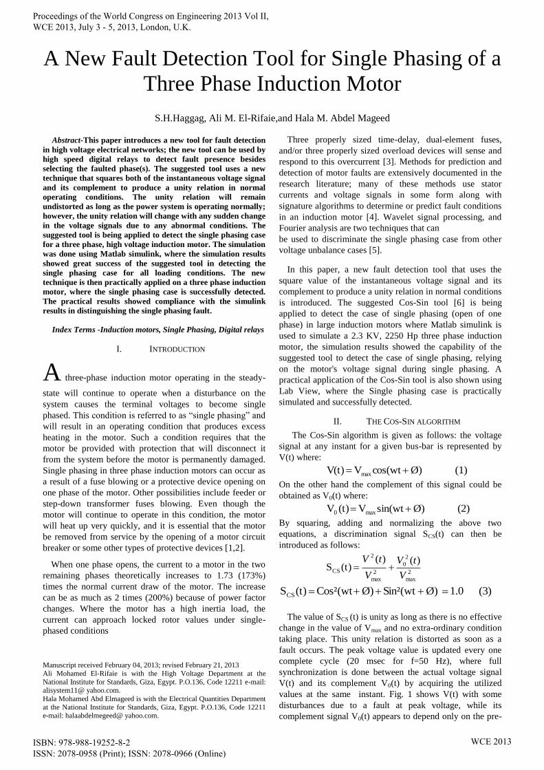
The case of one phase open in an induction motor is
simulated using MATLAB simulink [7]. Figure 3 shows the
simulink model for a three phase wound rotor induction
motor. The parameters of the simulated wound motor are as
given in Table I.
An open of one phase case is simulated after 1.5 seconds
of the motor operation. Figure 4 shows the deviation in the
nominal operating current values at the instant of fault
occurrence, the opened phase has a zero current, while the
currents of other phases increased to an extent of double the
normal operating current. Figure 5 shows the measured
voltage signal at the instant of fault occurrence, the opened
phase voltage decreased slightly in value while the other
phases remained unchanged. The suggested Cos-Sin
technique is applied and SCS (t) is obtained following
equations 1 to 3. The simulation is done for three different
load cases, no load, half load and full load where SCS(t) for
all cases are shown in Figure 6. It appears clearly that the
amount of maximum and minimum deviation from the unity
relation of SCS (t) increases as the load increases from zero
to maximum value. Table II, shows the deviation in the
unity value of SCS(t) during single phasing of phase A for a
time of 0.2 sec. From the shown values, it appears clearly
that the new Cos-Sin tool can safely detect the case of single
phasing (open of one phase) for high voltage, three phase
induction motors
Fig. 1. Normal voltage signal and its complement during abnormal
condition
Fig. 2. Discrimination signal during normal operation
TABLE I
PARAMETERS OF SIMULATED MOTOR
Parameter Value in SI units Unit
FREQUENCY 60 HZ
NOMINAL POWER 2250 HP
VOLTAGE (L-L) 2300 V
STATOR RESISTANCE 0.029 OHM
STATOR INDUCTANCE 0.000605 H
ROTOR RESISTANCE 0.022 OHM
ROTOR INDUCTANCE 0.000605 H
MUTUAL INDUCTANCE 0.0346 H
INERTIA FACTOR 63.087 KG.M2
PAIRS OF POLES 4
Fig. 3. Matlab simulink model for single phasing of a three phase wound rotor induction machine
Fig. 4. Deviation of the three phase currents during single phasing at phase-A
Fig. 5. Three phase voltages during single phasing at phase-A
0 100 200 300 400 500 600 700 800-600
-400
-200
0
200
400
600
Sampling Time
V, V
o
V(t) Vo(t)
Phase-A
Proceedings of the World Congress on Engineering 2013 Vol II, WCE 2013, July 3 - 5, 2013, London, U.K.
ISBN: 978-988-19252-8-2 ISSN: 2078-0958 (Print); ISSN: 2078-0966 (Online)
WCE 2013
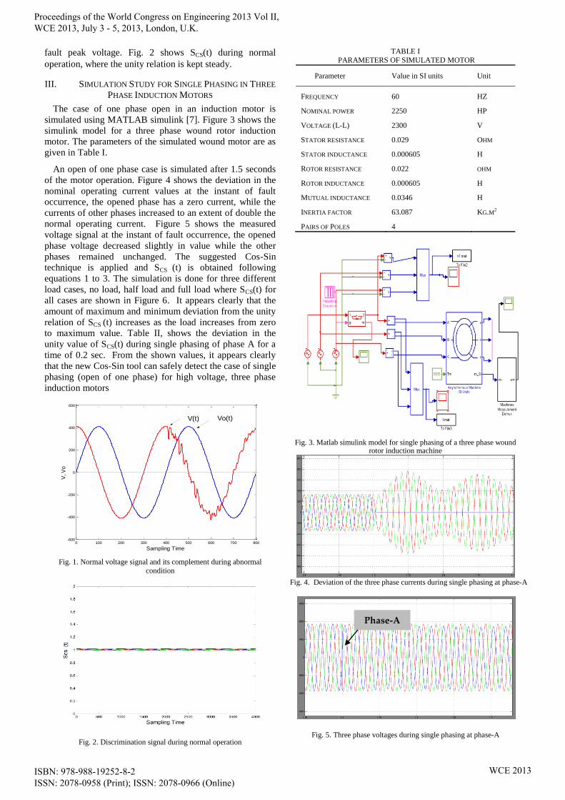
IV. FAULT DETECTION CRITERION FOR SINGLE PHASING
To avoid the errors that may occur in the unity relation
due to any variation in the peak voltage during normal
operation, and since the maximum permissible variation in
the peak value of the simulated network's voltage is 5 %, a
voltage detection threshold “Ɛ" of a value 0.025 (0.052) is
used; However, Ɛ will just act as a trigger that initiates the
operation of the Cos-Sin tool obtainer to start its mission of
detecting fault presence. This is done via calculating the
deviation “δ” in SCS (t) in one complete cycle time starting
from the instant of fault occurrence, and is given as follows:
)4.....(....................)(1
1 1
n
i
CS iSn
Where n: is the number of samples of one complete cycle of
the system power frequency.
One complete cycle time is used to avoid wrong triggering
due to transients.
TABLE II DEVIATION IN SCS (t) AT DIFFERENT LOAD VALUES OF THE
FAULTED PHASE
Load level δ-faulted phase
No load 0.185
Half load 0.115
Full load 0.101
Fig. 6-A. SCS(t) of the opened phase at no load.
Fig. 6-B. SCS(t) of the opened phase at half load
Fig. 6-C. SCS (t) of the opened phase at full load
Start
Read VA, VB, VC at motor terminals and IA, IB, IC
Apply the Cos-Sin tool to obtain SCS(t)
SCS(t)>1±Ɛ ? No
Yes
Calculate δ
δ ≥ Ɛ ?
Yes
Ii = Zero?
Yes
Declare Single Phasing Fault on Phase (i)
END
Fig.7. Flow chart of the proposed Cos-Sin tool for single Phasing detection in Three Phase Induction Motors
Figure 7 shows the flow chart of the proposed technique
for single phasing fault detection, where both the voltage
and current signals are used to differentiate between voltage
unbalance and single phasing.
V. PRACTICAL SIMULATION FOR SINGLE PHASING
The suggested tool was practically simulated to check its applicability for implementation in reality. All the network component were modelled where a 400 V power source linked to an auto transformer was used as a supply, a three phase low voltage induction motor that is loaded by a gear
Read IA, IB, IC
No
Declare
Unbalance
No
Proceedings of the World Congress on Engineering 2013 Vol II, WCE 2013, July 3 - 5, 2013, London, U.K.
ISBN: 978-988-19252-8-2 ISSN: 2078-0958 (Print); ISSN: 2078-0966 (Online)
WCE 2013
box was connected to it and a set of both single and 3 phase circuit breakers were connected in series and inserted in between. On the other hand the proposed technique was programmed using the LabVIEW software [8] and all system signals were delivered to the DAQ via voltage and current transformers where they occupied no.6 analogue inputs. Tables III and IV offer the specifications of the data acquisition card and the parameters of the used motor respectively.
Figure 8 presents the connection of the laboratory equipments where the motor phasing condition can be obtained using the single phase circuit breaker shown.
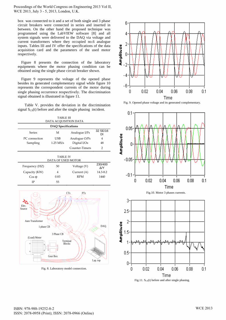
Figure 9 represents the voltage of the opened phase
besides its generated complementary signal while figure 10 represents the correspondent currents of the motor during
single phasing occurrence respectively. The discrimination
signal obtained is illustrated in figure 11.
Table V. provides the deviation in the discrimination
signal SCS(t) before and after the single phasing incident.
TABLE III
DATA ACQUISITION DATA
DAQ Specifications
Series M Analogue I/Ps 32 SE/16
DI
PC connection USB Analogue O/Ps 4
Sampling 1.25 MS/s Digital I/Os 48
Counter-Timers 2
TABLE IV
DATA OF USED MOTOR
Frequency (HZ) 50 Voltage (V) 230/400 Δ/Υ
Capacity (KW) 4 Current (A) 14.3-8.2
Cos φ 0.83 RPM 1440
IP 55
Auto Transformer
Lap. top
DAQ.
(Load) Motor
1 phase CB
CTs
Elec.
Gear Box
Terminal
3 Phase CB
Source
PTs
Blocks
Fig. 8. Laboratory model connection.
Fig. 9. Opened phase voltage and its generated complementary.
Fig.10. Motor 3 phases currents.
Fig.11. SCS(t) before and after single phasing.
Proceedings of the World Congress on Engineering 2013 Vol II, WCE 2013, July 3 - 5, 2013, London, U.K.
ISBN: 978-988-19252-8-2 ISSN: 2078-0958 (Print); ISSN: 2078-0966 (Online)
WCE 2013

TABLE V
DEVIATION "δ" DURING SINGLE PHASING INCIDENT AT NO LOAD
Period
covered
δ during
normal
operation
δ After
single
phasing
Half Cycle 0.05 0.205
Full Cycle 0.04 0.193
The calculated value for δ during normal operation
exceeded the threshold value used in simulation owing to
the harmonic content in the voltage signal besides the error
in detecting the peak value of the original voltage signal
every one complete cycle time. That resulted in using
another threshold value of Ɛ= 0.06 to avoid any wrong
operation. The practical simulation results acquired from the
laboratory model almost concurred with the MATLAB
simulink simulation outcomes, they both showed the
capability of the proposed Cos-Sin tool in capturing the case
of single phasing of a motor by using the voltage signal on
machine terminals.
VI. CONCLUSION
The paper introduced a new fault detection tool that can
be safely used to detect the case of single phasing in three
phase induction motors. The simulation results using Matlab
simulink showed complete success of detecting the single
phasing case for all load conditions. The laboratory results
showed full success of applying the new Cos-Sin tool
practically besides showing the capability of detecting the
single phasing fault and differentiating between voltage
unbalance case and single phasing one. The results of the
two implemented simulations showed a large extent of
compliance with each other and a great success in detecting
the open of one phase case. The suggested tool is
characterized by being simple, fast, accurate and executable
within digital relaying schemes.
REFERENCES
[1] W. H. Kersting, “Causes and effects of unbalanced voltages serving an induction motor,” IEEE Trans. Ind. Appl., vol. 37, no. 1, pp. 165–
170, Jan./Feb. 2001
[2] On line protection systems for induction motors, I. C¸ olak et al. Energy Conversion and Management 46 (2005) 2773–2786
[3] Benbouzid M, Vieira M, Theys C. Induction motors fault detection and localization using stator current advanced signal processing
techniques. IEEE Trans Power Electron 1999;14:14–22
[4] Thomson WT, Fenger M. Current signature analysis to detect induction motor faults. IEEE Ind Appl Mag 2001;7:26–34.
[5] Filippetti F, Franceschini G, Tassoni C, Vas P. Recent development of induction motor drives fault diagnosis using AI techniques. IEEE
Trans Ind Electron 2000;47:994–1004.
[6] S.H.Haggag, Ali M.El-Rifaie, R. M. Sharkawy "A novel measurement technique for extra high voltage bus bar fault detection" EEEIC 2012
pp 403-406
[7] Matlab Simulink ,Matlab R 2010b.
[8] National Instruments, LabVIEW, 2010.
Proceedings of the World Congress on Engineering 2013 Vol II, WCE 2013, July 3 - 5, 2013, London, U.K.
ISBN: 978-988-19252-8-2 ISSN: 2078-0958 (Print); ISSN: 2078-0966 (Online)
WCE 2013


![Hernan Ochoa - WCE Internals [RootedCON 2011]](https://img.pdfslide.net/doc/110x75/54827d4cb47959d80c8b479e/hernan-ochoa-wce-internals-rootedcon-2011.jpg)