Embed Size (px)
Citation preview

LAN Connection Type Andon Receiver
WCL-426R INSTRUCTION MANUAL V1.20
Please use this operation manual correctly on reading well.
Please keep it carefully to be able to read immediately, when required.


Table of Contents
1.Overview ..................................................................................................................................... 1
1-1.Introduction ......................................................................................................................... 1
1-2.Main Unit and Accessories ................................................................................................ 1
1-3.Safety Precautions (Be Sure to Read This) ...................................................................... 2
1-4.Outline .................................................................................................................................. 4
2.Specification ............................................................................................................................... 5
2-1.Radio Part Specification ..................................................................................................... 5
2-2.General Specification ......................................................................................................... 5
3.Part Names and Descriptions ................................................................................................... 6
4.Drawing ....................................................................................................................................... 7
5.Prepare to Start Communication .............................................................................................. 8
5-1.Installation of "Device Installer" ........................................................................................ 8
5-2.Factory Default IP Address ................................................................................................ 8
5-3.IP Address Settings and Procedure .................................................................................. 8
6.Settings ..................................................................................................................................... 15
7. Communication Command Function ..................................................................................... 17
7-1.Information Acquisition Command ................................................................................. 17
7-2.Setting Command ............................................................................................................. 17
7-3.Command Execution Result ............................................................................................ 17
8.Installation Procedure ............................................................................................................. 21
8-1.Receiver Installation ......................................................................................................... 21
8-2.LAN connector .................................................................................................................. 22
9.Description of Operation ......................................................................................................... 23
9-1.Basic Operation ................................................................................................................. 23
9-1-1.Opening ....................................................................................................................... 23
9-1-2.Receive Data from Transmitter ................................................................................. 23
9-2.LED Monitor ....................................................................................................................... 24
9-3.Processing at Power ON .................................................................................................. 26
10. After Service and Warranty ................................................................................................... 27

1
1.Overview
1-1.Introduction
This instruction manual describes the information required for using this product including overview,
installation, and operation of this product. Read this manual carefully before using this product. Keep this
manual handy so that you can take it out immediately.
▪ Do not use this product for the application that may cause harm to human body or damage to other
devices and equipment.
Do not use this product near the devices that may malfunction due to radio waves emitted from this
product.
▪ Because the communication performance is changed depending on the surrounding environment, be
sure to confirm the communication is established before installation of this product and then use it.
1-2.Main Unit and Accessories
■Receiver
Receiver main unit “WCL-426R”×1
AC adapter “ADB24050” x1
Cable Approx. 1.5 m
Antenna “TK-1842”×1

2
1-3.Safety Precautions (Be Sure to Read This)
This section describes the matters to be observed in order to prevent harm to the users and other persons
and damages to the property.
■ The following marks and displays classify and describe the extent of harm and damage caused by failing
to observe the display content and using this product wrongly.
This display column shows "a failure to do observe it could result in death or serious personal injury".
This display column shows "a failure to do observe it could result in only the personal injury or property damage".
■ Common matters in handling
● Avoid using this product in the humid or dusty place. Dusts or water enters the product, which may cause the fault, fire, or electric shock.
■ Handling this product
● This product is the wireless communication equipment made of precision parts. Do not disassemble or modify it. Or the accident or fault may occur.
■ Handling this product
● Do not use this product for application that requires the extremely high reliability affecting the human life.
● Do not use this product in the area which the radio wave reaches or not.
■ Handling the power supply
Be sure to observe the followings in order to prevent the accidents such as heat generation, damage, or
ignition of AC adapter and power cord.
● Do not place the AC adapter and power cord close to fire or insert them into fire. Or they may be burst and ignited, resulting in the accident.
● Use the AC adapter and main body only at the specified power supply voltage in order to prevent burst and ignition accidents.
! Warning
! Caution
! Caution
! Warning

3
● Do not use the AC adapter and main body at the location where they easily get wet. Or the accidents including heat generation, ignition, or electric shock and faults may occur.
● Do not touch the AC adapter, main body, power cord, and outlet with wet hands. Or the accident such as an electric shock may occur.
● Do not damage the power cord. Short-circuit or heat generation may cause fire or electric shock.
● Do not use the power plug with dusts attached. Short-circuit or heat generation may cause fire or electric shock.
● Do not give a strong shock to the AC adapter. Or the accident or fault may occur.
● If you find a deformation in the AC adapter, do not use it. Or the accident or fault may occur.
● Do not charge the main body at the location where the flammable gas is generated. Or the ignition accident may occur.
● Never disassemble the AC adapter. Or the accident or fault may occur.
■ Never disassemble the AC adapter.
Remove the power plug from the outlet because it may cause fire and electric shock. Request the dealer
or our company to repair it.
● When smoke comes or there is a strange smell, immediately stop usage and remove the power plug from the outlet because it may cause fire and electric shock. Request the dealer or our company to repair it.
● If the cord is damaged, do not use it. Using the cord damaged continuously may cause fire or electric shock.
■ Reliability of wireless communication
As wireless communication has properties that are different from those of wired communication,
communication errors may occur due to the following.
・Exceeds the communication distance.
・Enters a dead zone.
・Interfered by strong jamming
If signals are often jammed, or being jammed leads to operational problems, stop using the systems and
restart using the systems after removal of the cause.
Radio waves may not be received due to various reasons other than the above. Please understand this
before using the systems.
* A dead zone is an area where the radio wave transmitted from the transmitter becomes extremely weak
due to radio waves reflected from walls or other objects.

4
1-4.Outline
WCL-426R is a LAN connection type Andon*1 receiver (hereinafter called “receiver”).
The receiver can wirelessly receive in real-time trouble occurrence reports transmitted from the AN426TⅡ
transmitter installed at the workstations and machines of the production line.
In addition, the receiver can externally output the received reports of trouble occurrence via LAN.
By utilizing and analyzing the information of trouble occurrences on the production line with applications on
computers, tablets and in the cloud, the receiver can be useful for visualizing and improving the operation
status of the production line.
Using the Windows application “Production Process Support Software for WCL Series WCL plus,” you can
save the trouble occurrence history received by up to 10 Andon receivers in the CSV format.
1. At the transmitter, there are two selectable input methods for reporting trouble occurrences: one for
workers with four push-buttons (orange, red, green, and white) and one for machines with four external
inputs (orange, red, green, and white). According to possible trouble occurrences in the production line,
you can assign each color a meaning, such as red for an exception occurrence, orange for parts out of
stock, green for requesting transportation of finished products, or white for trouble solved.
2. When using the receiver linked to a wireless Andon series AN426Ⅱ, one receiver can wirelessly
communicate with up to 800 transmitters and a maximum of 10 receivers can be used in a factory. This
enables trouble occurrence reports to be collected from up to 8,000 locations in a factory.
When using the receiver with the transmitter without linking to a wireless Andon series AN426Ⅱ, each
receiver can wirelessly communicate with up to 1,000 transmitters and a maximum of 10 receivers can
be used within a factory. This enables trouble occurrence reports to be collected from up to 10,000
locations in a factory.
*1: A system to notify management, maintenance, and other workers of a quality or process problem.
5
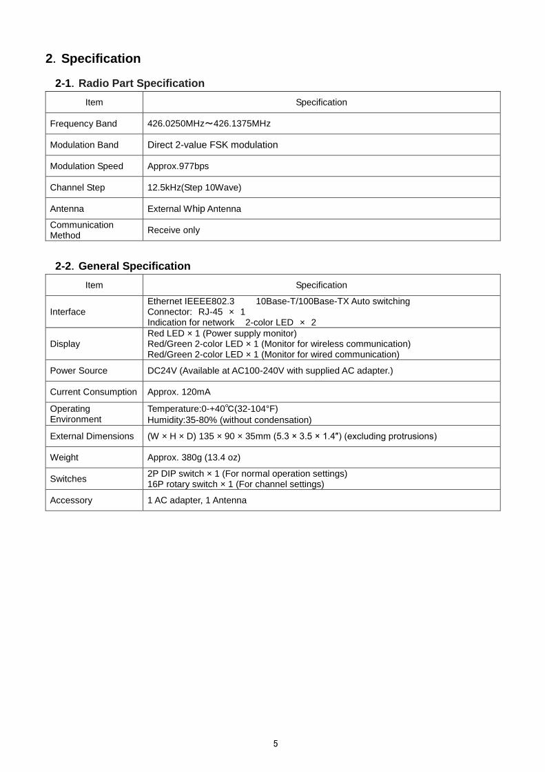
2.Specification
2-1.Radio Part Specification
Item Specification
Frequency Band 426.0250MHz~426.1375MHz
Modulation Band Direct 2-value FSK modulation
Modulation Speed Approx.977bps
Channel Step 12.5kHz(Step 10Wave)
Antenna External Whip Antenna
Communication Method
Receive only
2-2.General Specification
Item Specification
Interface Ethernet IEEEE802.3 10Base-T/100Base-TX Auto switching Connector: RJ-45 × 1 Indication for network 2-color LED × 2
Display Red LED × 1 (Power supply monitor) Red/Green 2-color LED × 1 (Monitor for wireless communication) Red/Green 2-color LED × 1 (Monitor for wired communication)
Power Source DC24V (Available at AC100-240V with supplied AC adapter.)
Current Consumption Approx. 120mA
Operating Environment
Temperature:0-+40℃(32-104°F)
Humidity:35-80% (without condensation)
External Dimensions (W × H × D) 135 × 90 × 35mm (5.3 × 3.5 × 1.4″) (excluding protrusions)
Weight Approx. 380g (13.4 oz)
Switches 2P DIP switch × 1 (For normal operation settings) 16P rotary switch × 1 (For channel settings)
Accessory 1 AC adapter, 1 Antenna

6
Setting switch
Connector for antenna
LED monitor
LAN Connector
DC jack
Mounting hole
3.Part Names and Descriptions
Name Function
Connector for antenna
Connector for connection to the antenna. (BNC-J Connector) Attach the supplied antenna.
Mounting holes Mounting hole of φ4.5 × 4
DC jack DC jack for connection of the included AC adapter.
Setting switch DIP switch and rotary switch for settings.
LED monitor LEDs for power supply, wireless communication and wired communication.
LAN Connector Connector for LAN connection. (RJ-45)

7
24
37
90
75
4-φ4.5取付穴
125115135
10 10
35
(41)
(160)
4.Drawing
4-φ4.5 Mounting hole

8
Link LED Activity LED
RJ-45
- Fig. 1 Screen to start Device Installer -
5.Prepare to Start Communication
Before use of the receiver, set each receiver according to the use environment.
Set the IP address and other required items of the receiver by using Lantronix’s Windows-based software,
“Device Installer”.
5-1.Installation of "Device Installer"
Download “Device Installer” from Lantronix’s WEB site (https://www.lantronix.com/products/deviceinstaller/)
to install it on your PC.
Connect the receiver to the HUB capable of communicating with the PC on which “Device Installer” is
installed.
CAUTION To connect the receiver to the PC with “Device Installer” installed using a LAN cable, be sure to use a cross LAN cable.
Check the left LED on the LAN connector (RJ-45) of the receiver to see if the Link LED is ON.
When connected to 10Base-T, the Link LED lights up in orange. When connected to 100Base-TX, the Link
LED lights up in green.
If the Link LED is not ON, the receiver cannot communicate with the network. Confirm if the LAN cable and
HUB are correctly connected.
5-2.Factory Default IP Address
The factory default IP address of the receiver is as follows:
IP Address 192.168.3.100 Subnet Mask 255.255.255.0 Default Gateway 0.0.0.0 Port No. 50001
5-3.IP Address Settings and Procedure
Check that the power of the receiver is ON and that the receiver is properly connected to the HUB or PC,
and then start “Device Installer” from the start menu.
The connected receiver is displayed on the main window (Fig.1).
IP address of the receiver connected to the LAN
IP address

9
- Fig. 2 Select IP address of Xport to change -
- Fig. 3 IP address assignment -
To change the IP address, select the address of the X port on the left of the screen.
Click “IP assignment button”, and the screen is displayed as shown in Fig.3. Select to assign an IP address
automatically or specify an IP address directly. This document explains about specifying an IP address.
Check “Assign a specific IP address” and click the “Next” button.
IP assignment button
Select IP address to change
IP address assignment method
Automatic IP address acquisition
Allocation of specific IP address
Device details
Next

10
- Fig. 4 IP address input screen -
- Fig. 5 Assignment input screen -
Enter the IP address, subnet mask and default gateway.
*Before setting an IP address, obtain permission from the network administrator.
Click “Next” button.
Click “Assignment” button.
IP settings
IP address
Subnet mask
Default gateway
Next
Assignment

11
- Fig. 6 Input end screen -
- Fig. 7 IP address display screen after change -
When the setting is completed, the “Exit” button becomes active.
It may take some time before the setting is completed. Please wait until the setting is completed.
Click the “Exit” button, and the screen is displayed as shown in Fig.7. Confirm if the IP address has changed
properly.
CAUTION If the IP address set by the customer is already used on the network, the signals will run into each other. Set another IP address.
CAUTION This product is intended to be used on a closed network that is not connected to the internet. Do not use this product in an open network environment that is connected to the internet.
Assignment
Task progress
Completed
Finish

12
Navigate button
- Fig. 8 WEB configuration setting screen -
- Fig. 9 Password input screen -
■Change Password
The WEB screen (Web Manager) inside X port requires user authentication by password.
Change the default password in the following procedure.
CAUTION Leaving the default password can cause a security risk to the product. Be sure to change the default password.
Click the “WEB configuration” tab on the screen in Fig.7, and the screen in Fig.8 is displayed.
Click the “Navigate” button and the password entry screen in Fig.9 is displayed.
Please leave the user name blank.
Enter the following password. When the entry is completed, click the “OK” button.
Initial password NuM7?FrC@nVT8Z1Q
Web Configuration
User name
Password

13
“Server” button.
- Fig. 10 Web Manager initial screen -
On the “Web Manager” screen in Fig.10, click the “Server” button.

14
- Fig. 11 Server settings initial screen -
Click the “Server” button, and the “Server Settings” screen in Fig.11 is displayed.
① Set the “Enhanced Password” radio button to “Enable”.
② Enter a new password (up to 16 characters) in the “Telnet/Web Manager Password” field.
③ Enter the same password as ② in the “Retype Password” field.
④ Click "OK" button. If the passwords entered in ② and ③ match, "Done!" will be displayed to the right of
the "OK" button. If the passwords entered in ② and ③ are different, an error message "Passwords do
not match. Please retry again." is displayed. Retry ② and ③ again.
⑤ Click "Apply Settings" button.
When the process is completed, the password entry screen is displayed. Enter the set password and
press the "OK" button. (Please leave the user name blank.) If login is successful, the settings are
complete. Press the “x” button on the top right of the screen and the application exits.
CAUTION When reconfirming the changes made to the settings, the changes may not be reflected in the display. In that case, reboot the software (Device Installer) and check the changes again.
■About settings various parameters
Various parameters can be set on the WEB screen (Web Manager) inside X Port. However, do not change
the settings of the parameters. The default values are set to work properly.
①
②
③
⑤
④

15
6.Settings
Use the rotary switch, DIP switches or Ethernet communication command to set the receiver.
Details of the settings and methods for changing the settings are as follows:
Turn OFF the power of the main unit before changing the settings of the rotary switch or the DIP switch.
Setting contents Setting by switch Setting by Ethernet communication
command
Channel settings 〇*1 〇*2
Ethernet communication command settings
〇 ×
Terminal code settings of Ethernet communication command
× 〇*2
*1: This setting is available only when the Ethernet communication command is set to “Invalid”.
*2: This setting is available only when the Ethernet communication command is set to “Valid”.
For the setting by the Ethernet communication command, refer to "7. Communication Command Function".
■Channel settings
Set the channel settings according to the transmitter that will communicate with the receiver.
< Channel >
SW2 Channel Frequency
(MHz) SW2 Channel
Frequency (MHz)
1 1 426.0250 9 9 426.1250
2 2 426.0375 A 10 (426.1375)
3 3 426.0500 B 10 (426.1375)
4 4 426.0625 C 10 (426.1375)
5 5 426.0750 D 10 (426.1375)
6 6 426.0875 E 10 (426.1375)
7 7 426.1000 F 10 (426.1375)
8 8 426.1125 0 10 426.1375
*When A to F are set, 0 (channel 10) is set for the channel.

16
■Ethernet communication command settings
Select Valid/Invalid for the Ethernet communication command.
When this setting is “Valid”, the devices are set to the setting of the Ethernet communication command. The
settings are stored until the power is ON next time.
When this setting is “Invalid”, the devices are set to the setting of the rotary switch or the DIP switch.
When this setting is “Invalid”, the receiver returns an error response after receiving the Ethernet
communication command and the command will not be reflected as the setting of the device.
SW1-1 OFF ON
Ethernet communication
command settings Invalid Valid
*SW1-2 is not available.

17
7. Communication Command Function
The Ethernet communication command allows information acquisition and device settings of the receiver to
be changed.
To use the Ethernet communication command function, “Ethernet communication command settings” of the
DIP switch, SW1-1 must be valid.
7-1.Information Acquisition Command
@?Command<Space>[Param]<Terminal code>
1 First code “@?” Fixed (40H, 3FH)
2 Command Command for acquiring each information
3 Space If an argument exists, separate the argument with spaces (20H).
4 Param (Argument) If there are multiple arguments, separate them with”,” (2CH).
5 Terminal code Use one of CR/LF/CRLF. (Value set by the command for setting the terminal code. The default value is CRLF.)
7-2.Setting Command
@Command<Space>[Param]< Terminal code >
1 First code “@?” Fixed (40H)
2 Command Command for each settings
3 Space If an argument exists, separate the argument with spaces (20H).
4 Param (Argument) If there are multiple arguments, separate them with”,” (2CH).
5 Terminal code Use one of CR/LF/CRLF. (Value set by the command for setting the terminal code. The default value is CRLF.)
7-3.Command Execution Result
<At normal termination>
When the setting command terminates normally, the command execution result is as follows:
<First code>Command<Space>OK<Terminal code>
1 First code “@?” Fixed (40H)
2 Command Command for each settings
3 Space Separate Command and OK with a space (20H).
4 OK (Execution result) “OK” (4FH,4BH) ASCII string
5 Terminal code Use one of CR/LF/CRLF. (Value set by the command for setting the terminal code. The default value is CRLF.)

18
When the information acquisition command terminates normally, the command execution result is as
follows:
When a response with multiple values is included, a response separated with commas for each data
element is returned.
<First code>Command<Space><result1>,・・・,<result n><Terminal code>
1 First code “@?” Fixed (40H,3FH)
2 Command Command for acquiring each information
3 Space Separate Command and Result with a space (20H).
4 Result (Execution result) Separate multiple execution results with”,” (2CH).
5 Terminal code Use one of CR/LF/CRLF. (Value set by the command for setting the terminal code. The default value is CRLF.)
<When abnormal termination>
<First code>Command<Space>Error=<X>.<Y><Terminal code>
1 First code “@?” Fixed (40H,3FH)
2 Command Command for acquiring each information
3 Space Separate Command and Error with a space (20H).
4 Error (Error code) ASCII string in the format “Error=X.Y” X indicates an error group and Y indicates an error number. They are separated with a period.
5 Terminal code Use one of CR/LF/CRLF. (Value set by the command for setting the terminal code. The default value is CRLF.)
Error code specification
<Error group>
Numeric value
Meaning
0 No error
1 Command analysis error related
2 Input range error related
3 Error group depending on the status of the receiver
4 Memory error related
F Other error

19
<Error code>
Error group (X) Error number (Y) Meaning
1 1 No first code (“@”)
1 2 Non-existent command
1 3 Character code is included in the set value
1 4 Command format error
1 5 Excessive command string length
2 1 Out of the set value range
3 1 Ethernet communication command invalid
4 2 Serial number reading error
4 3 Receiver settings reading error
F F Other errors

20
Command List
■Information acquisition only
Transmission format Execution result Meaning
@?Version @?Version 1.00 *1 Software version acquisition
@?ModelName @?ModelName WCL-426R Type acquisition
@?SerialNumber @?SerialNumber A00001 *2 Serial number acquisition
*1: Example when the soft version is 1.00.
*2: Example when the serial number is A00001.
■Information acquisition/setting command
Transmission format Execution result Value range Meaning
@?Channel @?Channel X X=1~10 Channel settings acquisition
@Channel X @Channel OK / @Channel Error=Code
X=1~10 Channel settings
@?Termination
@?Termination X *Be sure to specify CRLF for the terminal code of this command.
X = 0~2
0:(CRLF)
1:(CR)
2:(LF)
Terminal code settings acquisition
@Termination X
@Termination OK/ @Termination Error=Code *Be sure to specify CRLF for the terminal code of this command.
X = 0~2
0:(CRLF)
1:(CR)
2:(LF)
Terminal code settings
*The commands are case sensitive.

21
8.Installation Procedure
8-1.Receiver Installation
Communication performance highly depends on the installation environment. Install the receiver as follows.
・ Keep the antenna away from metal sheets or wires, and prevent the antenna from becoming parallel to
them.
・ Keep the antenna away from noise sources.
・ Select a location where there are no shielding objects between the antennas of the transmitter and the
receiver.
・ The receiver is neither dust-proof nor drip-proof.
*Do not install the receiver in the following locations:
・ Locations exposed to direct sunlight.
・ Locations with high humidity.
・ Near a television or radio.
・ Near machines that spark, such as a welding machine.
・ Locations where strong magnetic field is generated.
・ Locations surrounded by steel frames or metal walls.
・ Near any devices that could malfunction due to radio waves from the systems.
・ Place the receiver where it can be seen easily and clearly from the transmitter.
Fix the receiver to a stable surface using the mounting holes.
・ Connect the LAN connector of the receiver to the switching hub or the PC’s LAN connector with the
cable.
Please use the cable of the category 5 or higher standard.
・ The receiver is not equipped with AutoMDI/MDI-X function to determine the LAN port. To connect the
receiver to the PC’s LAN port directly, use a cross-wired LAN cable.
HUB LAN cable
LAN cable (cross-wired)

22
8-2.LAN connector
For the connector use RJ45 type.
The pin specifications are shown in the following table.
Pin number Signal name
1 TX+[Transmission data(+)]
2 TX-[Transmission data(-)]
3 RX+[Receiving data(+)]
4 Unused
5 Unused
6 RX-[Receiving data(-)]
7 Unused
8 Unused
Please use the cable of the category 5 or higher standard.
1・・・・・・8

23
9.Description of Operation 9-1.Basic Operation
9-1-1.Opening
The power LED lights up (Red).
The LEDs for wireless communication and wired communication lit orange, and then go out after 10
seconds. While the LEDs for wireless communication and wired communication are lit orange, the receiver
is starting up, and thus does not communicate with connecting devices or receive data from the transmitter
until the LEDs go out.
9-1-2.Receive Data from Transmitter
Upon receipt of a message from the transmitter, the receiver generates the output of the information in
TCP/IP.
Message data with the same channel as the receiver is generated. After receiving a message, when
receiving the same message within 2 seconds, the message will be thrown away after reading and will not
be generated. The output data formats are as follows.
The items between Model and Output power settings are separated with commas [,].
First code
Space
Mo
del
,
Seria
l num
ber
,
CH
,
SE
T
,
UN
IT
, ID
,
Ora
nge k
ey F
LG
,
Red k
ey F
LG
,
Gre
en k
ey F
LG
,
White k
ey F
LG
,
Ora
nge t
erm
inal F
LG
,
Red t
erm
inal F
LG
,
Gre
en t
erm
inal F
LG
,
White term
inal F
LG
,
Com
munic
atio
n type
,
Tra
nsm
it a
nd r
eceiv
e
settin
gs
,
Outp
ut
pow
er
settin
g
Term
inal code
Separate the items between Model and Output power settings with commas “,”.
Item Contents Number of bytes
First code “@!CallData” ASCII string 10
Space Space (20H) 1
Model “WCL-426R” ASCII string 8
Serial number Serial number in ASCII One alphabet letter + 5-digit serial number identifier, starting with “A00001”.
6
CH Channel settings ASCII string: “00” – ”10”
2
SET SET No. setting value of the transmitter: '0' (30H) – '9'(39H)
1
UNIT UNIT No. setting value of the transmitter: '0' (30H) – '9'(39H)
1
ID(KIKI) ID(KIKI) No. setting value of the transmitter: '0' (30H) – '9'(39H)
1
Orange to White key FLG
Key information input to the transmitter: '0' (30H):OFF/ '1'(31H):ON
1
Orange to White terminal FLG
Terminal information input to the transmitter: '0'(30H): OFF/ '1' (31H):ON
1
Communication type
’5’(35H):Normal transmission
’6’(36H):Event transmission 1
Transmit and receive settings(Unused)
Unused '0' (30H)
1
Output power settings (Unused)
Unused ”00” ASCII string
2
Terminal code One of CRLF / CR/ LF 2 (for CRLF) 1 (for CR/LF)
*Separate the items between Model and Output power settings with commas “,” (2CH).

24
Power supply LED (Red)
Wireless communication LED (Red/Green)
Wired communication LED (Red/Green)
LAN connector LED (Orange/Green)
9-2.LED Monitor
Check the status of the power supply, wireless communication and wired communication on the LED
monitor.
■At power ON
The power LED lights up (Red).
The LEDs for wireless communication and wired communication light up in orange, and then go out after 10
seconds.
■Power supply LED
State Monitor
Power ON Red LED lights
■LED for wireless communication
State Monitor
Receiving wireless data Red LED lights
■LED for wired communication (Internal microcomputer <=> LAN communication module)
State Monitor
Microcomputer -> LAN communication module
Green LED lights
LAN communication module -> microcomputer
Red LED lights
■At error occurrence
Error event LED for wireless communication
LED for wired communication
Serial No. reading error Orange LED blinking (Intervals of 100msec.) Continues blinking until the power is OFF.
Device setting read error - Orange LED blinking (For 5 seconds in intervals of 100msec.)

25
Link LED Activity LED
■LAN connector
Link LED Activity LED
LED color Contents LED color Contents
Lights off Unconnected Lights off No communication
Orange LED light 10Mbps Orange LED light
Communicating in half duplex
(Turns ON only during communication)
Green LED light 100Mbps Green LED light
Communicating in full duplex
(Turns ON only during communication)

26
9-3.Processing at Power ON
At power ON, the receiver reads the settings required to work. If the receiver fails to read them, the LED
indication and settings may be forcibly initialized.
■Read serial number
At power on, the receiver reads the serial number stored in the code flash region.
If an error occurs while reading the serial number, the LEDs for wireless communication and wired
communication blink in orange (blinking interval of 100msec). Also, error information output is generated in
TCP/IP. If an error occurs while reading the serial number, the LED for wireless communication and wired
communication continue blinking until the power is OFF. The error information output to be generated is as
follows:
■Read the channel settings and the terminal code settings for the Ethernet communication command.When
the Ethernet communication command is valid, the receiver reads the channel settings and the terminal
code settings for the Ethernet communication command stored in the data flash region, at power on.
When the Ethernet communication command is invalid, the receiver reads the channel settings from various
switches.
When an error occurs while reading them, the LEDs for wireless communication and wired communication
blink in orange for 5 seconds (blinking interval of 100msec). Also, error information output is generated in
TCP/IP. The error information output to be generated is as follows:
In the following cases, the set values are forcibly set to default.
• Failed to read the channel settings and the terminal code settings for the Ethernet communication
command.
• Set the Ethernet communication command to valid for the first time.
The default values are as follows:
Device settings Initial value
Channel settings 1
Terminal code settings of Ethernet communication command
CRLF
■Initialization of wireless module
At power ON, the receiver initializes the wireless module.
When the above symptom occurs and the error continues, there may be some damage to the module. In
that case, please contact the sales distributor you purchased the product from, or contact our sales
department.
@!ErrorData Error=4.2
@!ErrorData Error=4.3

27
10. After Service and Warranty
I f the problem persists even after a remedy action is taken or if it is unclear which remedy action should be
taken, then contact the dealer where the product was purchased or our Sales Department with the following
information:
Product name / Serial No. / Service environment,
External equipment connected,
Operating sequence to error initiation, and
Specific description of error, etc.
The user is prohibited by law from disassembling or making modification to the unit or otherwise may be subject to punishment.
The Company sets forth the Warranty Terms and Conditions herein for the benefit of customer to ensure
product assurance after shipment. In case of failure, the Company will remedy the defect by repair or
replacement.
■ Warranty Period
Unless otherwise specified, the warranty period is 13 months after shipment of products from the
Company. During the Warranty Period, the Company remedy defect free of charge in accordance with the
terms of this Warranty. If you have any questions concerning remedy and after-sales services during the
Warranty Period, please contact your dealer or our Sales Department.
■ Scope of Warranty
In case any failure occurs attributable to the Company during the Warranty Period, the defect will be
remedied free of charge either by repair or replacement with a substitution. To obtain warranty service,
contact your dealer or our Sales Department. The Warranty Period after repair or replacement is 13
months from the date of initial shipment of the relevant product or 6 months from the date of shipment of
the substitution, whichever period of time is greater. Only the hardware part of the Product is covered.
The Warranty does not apply to the following, even during the Warranty Period.
1. Failure or damage caused by in appropriate handling on the part of customer, such as drop, shock etc.
during transportation or move.
2. Failure caused by disassembly or modification of the main unit by customer.
3. Failure or damage caused by natural disaster, such as fire, earthquake, flood etc. and abnormal
voltage.
4. Failure caused by malfunction of devices connected to the Product other than those designated by the
Company.
5. The Warranty does not cover accessories such as an AC adopter, an antenna, a connecting cable, etc.
6. The Product that has been repaired, adjusted or modified by a third party.

28
7. Replacement of consumables or limited-life goods (including batteries).
Consumables and limited-life goods include the following:
①Switches (limit switch, button switch etc.)
②Battery cells, batteries (dry cell, button battery etc.)
③Other goods considered to be consumables or limited-life goods by usage.
8. Failure caused by not using the Product in accordance with the User Guide
■ Initial Defect
The Warranty for initial defect is valid for 30 days from the date of shipment of the Product. In case an
initial defect is found, the defective product should be shipped to your dealer or our Sales Department
within the period mentioned above. Upon confirmation of the initial defect, the defect will be remedied
free of charge either by repair or replacement with a new one. The shipping costs for the initial defect will
be borne by the Company. However, this shall apply only within Japan. The payer of overseas shipping
costs including insurance fee, custom duty etc. for a customer who purchased the Product outside Japan
shall be determined on mutual consultation.
■ Disclaimer
The Company will not be responsible for any direct or indirect damage and financial loss caused by
malfunction or failure of the Product or its use.
■ Period for Charged Repair
After the Warranty Period expires, the Company will repair the Product for a fee on customer’s request
during a 5 year-period after termination of the Product on the condition that spare parts are available in
stock at the Company. However, in case of unavoidable reasons such as elimination of parts, alternative
parts or a substitution may be supplied.
■ Other
● Regardless of the Warranty Period, repair shall only be performed in principle at the Company for
purposes of using measurement equipment etc. for adjustment. The shipping costs incurred at the
time of shipment shall be borne by customer. Visiting repair service or a substitution during the
Warranty Period are available on request for a fee. Please contact your dealer or our Sales
Department.
● If our Technical Department finds it difficult to reproduce failure of the Product received for repair, repair
service or replacement may not be performed. Also, technical investigation expenses for failure
reproduction may be charged separately.
● Note that any information about the Product on our website, catalogues, manuals, technical materials
and other materials is subject to change without notice.

HERUTU ELECTRONICS CORPORATION
62-1 Toyooka-cho, Kita-ku, Hamamatsu, Shizuoka, 433-8103 Japan
(Sales dept) TEL.+81-053-438-3555 FAX. +81-53-438-3411
Website URL https://www.herutu.co.jp/en/ E-mail [email protected]


![App Development Guide for Samsung Smart TV[V1.20][1] 3](https://img.pdfslide.net/doc/110x75/545f337cb1af9feb588b4b39/app-development-guide-for-samsung-smart-tvv1201-3.jpg)