Embed Size (px)
Citation preview

1M9:11159
REFERENCE COPY
UNCLASSIF1ED
TECHNICAL MEMORANDUM
WEAR TEST RESULTS OF CANDIDATE MATERIALS FOR THE
OK-542 TOWED ARRAY HANDLING MACHINE LEVEL WINDER
Date: 29 December 1994
Distribution Statement A. Approved for public release; distribution is unlimited.

1M941159
ABSTRACT
This Technical Memorandum (TM) reports the fmdings of a series of wear tests conducted for possible replacement materials for the Towed Array Handling Machine Level Winder Pawl. In the existing system, the Pawl is manufactured from C63000 Nickel-Aluminum-Bronze (NiAl-Br) and the drive shaft, from C71500 70-30 Copper-Nickel (Cu-Ni). The problem under investigation is that of severe wear on the sides of the Pawl occurring within short time periods.
A test apparatus was designed and built that simulated operating conditions of the Handling Machine. Speed, loading, environment, and shaft material were designed to match that of the system. Different materials were then selected as candidate Pawl replacements and tested.
Materials that were tested consisted of standard and specialty materials. Coating processes were also investigated. The standard materials consisted of 304 and 316 Stainless Steel, Inconel 625, Nickel-Aluminum-Bronze, and Titanium. The specialty materials: Inconel 625, Monel, Stainless and Stellite, were clad-welded metals on a base of 1040 Carbon Steel. Finally, an economic carbide coating was deposited on a 316 Stainless Steel and Inconel 625 sample.
Within a short time span, from the materials discussed, varied differences in performance were observed and several conclusions were reached. First, the existing material, NickelAluminum-Bronze, was one (1) of the worst performers. As a result of the experiment, this sample showed the greatest amount of damage in the shortest period of time. The Inconel 625 bar stock that was tested performed the best. It sustained the least amount of damage for one (1) of the longest durations of the test.
AD:MINISTRATIVE INFORMATION
This Document was prepared for the Mechanical Design and Systems Installation Branch (Charles Gray, Code 423) for OK-542 Towed Array Handling Machine using Job Order K15040.
ACKNOWLEDGl\tiENTS
The author wishes to thank the following individuals for their assistance and support: Mr. Phil Watrous (Code 4211) for scrounging the components for and building the Wear Machine and monitoring testing and to Messrs. Roger Tryon and Eric Von Winkle of McLaughlin Research Corporation, Waterford, Connecticut, for fabricating samples and test monitoring.
1

1M941159
TABLE OF CONTENTS
Abstract .................................................. .................. . .................. .i Administrative Information ..... . ..................................... . ... .. ............... ii Acknowledgments .................... . ................. ..................................... iii Introduction ................................................................................... 1 Experimental Apparatus . ............................... .. ........ .. .. . ..................... 1 Experimental Technique .... . ........ ..................... .................................. 2 Test Results ............................................................. . ..................... 3 Conclusions ................................................................................... 4
LIST OF FIGURES
1. Level Winder Pawl and Shaft ....................................................... 6 2. Pawl Wear .............................................................................. 7 3. Shaft Wear ... . . ................ .. .. . . .. .............................................. . .. 8 4. Wear Testing Apparatus Schematic ................................................ 9 5. Wear Testing Photograph A . .................................... .... .. . ........... .10 6. Wear Testing Photograph B ....................................................... .11 7. Clad Inconel 625 ............... . ................. . .................................. 12 8. C71500 Cu-Ni Wheel/Clad Inconel 625 ........ .. .................. .. .......... 12 9. Clad Monel ............................................... . ........................... 13
10. Clad Monel .. . .............. .. .. .... . . . ...... . .. . ........ . .......................... . 13 11. Clad Stainless ...................................................... . ............... . 14 12. C71500 Cu-Ni Wheel/Clad Stainless ............................................ 14 13. Clad Stellite . ................... ..................................................... 15 14. C71500 Cu-Ni Wheel/Clad Stellite ........................... .. .. .. ............. 15 15. 304 Stainless ..................... ............... . .................... . ....... . ...... 16 16. C71500 Cu-Ni Wheel/304 Stainless ............................................. 16 17. 316 Stainless ....................................... . ................................ 17 18. C71500 Cu-Ni Wheel/316 Stainless ............................................. 17 19. Inconel 625 Bar ..... ... . . .. . .... ....... .. . ... .... . ....... . ....... . ................. 18 20. C71500 Cu-Ni Wheel/Inconel 625 Bar ....................... .. ................ 18 21. Titanium Bar ...................... . .. . ............................................ . 19 22. C71500 Cu-Ni Wheel/Titanium Bar .......................... . : .. .. ............ 19 23. C63000 Ni-Al-Br Pawl ...... ................................................ ..... 20 24. C63000 Ni-Al-Br Pawl ...................................................... . .... 20 25. C71500 Cu-Ni Wheel/C63000 Ni-Al-Br ....................................... 21 26. C71500 Cu-Ni Wheel/C63000 Ni-Al-Br ....................... . ............... 21 27. Rocklinized Samples ......... .................... ........... . . . .. . ................ 22
11

1M941159
LIST OF FIGURES (CONT.)
28. Rocklinized 316 Stainless ... . .................. . .................................... 23 29. C71500 Cu-Ni Wheel/Rocklinized 316 Stainless ................................ 23 30. Rocklinized Inconel 625 .......................................... . .................. 24 31. C71500 Cu-Ni Wheel/Rocklinized Inconel 625 .............. . ................... 24 32. C63000 Pawl Material and Inconel 625 Bar Test Comparison ................ 25
LIST OF TABLES
1. Level winder Pawl Material Wear Test Summary ............... . ................ 26 2. Level Winder Wheel Wear Test Summary .. . .... . .............. .. ................. 27
LIST OF REFERENCES
1. Naval Underwater Systems Center Memorandum Ser 44211L/56 ............. 28
APPENDICES
A. Material Specifications ........ . ...... . ........ . .................. . ................... A-1 B. Calculations . ........ . ........ .. ....... . ................................................. B-1 C. Rocklinizing Data Sheet .............. .......... . . ................... ............. ..... C-1
iii

TM941159
INTRODUCTION
Code 21 has been experiencing a wear problem associated with the OK-542 Towed Array Handling Machine Level Winder Pawl and Shaft. It seems that there is an excessive amount of wear manifesting itself on the Pawl in an unreasonably short period of time. Figure 1 is a schematic representation of these parts and Figures 2 and 3, respectively, are photographs showing the wear on a Pawl and Shaft. The material specifications (specs.) are included in Appendix A for reference.
Initially, the Materials Laboratory (hereinafter referred to as the Materials Lab) was tasked to conduct a series of hardness measurements on three (3) Pawls and three (3) Shafts. Reference (a) reports the results of this investigation.
The effort continued to focus on evaluating the Ni-Al-Br material. The decision had been made to conduct a series of experiments in which many different materials would be evaluated under operating conditions similar to those of the actual Handling Machine. There was, however, a time constraint on the work. It was imperative, therefore, to accelerate the processes involved.
The Materials Lab, working in conjunction with personnel from the Code 4211 Pressure Laboratory (hereinafter referred to as the Pressure Lab), was able to devise an apparatus from in-house components that would simulate the contacting components, place them under a load. lubricate them, and move them at the same speeds as those of a Handling Machine.
For the most part, the materials were selected from available stock within the Naval Undersea Warfare Center Newport Division Detachment New London (NUWCNPTDIVDETNL) Machine Shop facilities. The tested materials included the following weld cladding on a 1040 mild steel base: Inconel 625, Monel, Stainless, and Stellite. Other tested bar-stock materials were 306 and 316 Stainless, Inconel625, Titanium, C63000 Ni-Al-Br, and Rocklinized Inconel 625 and 316 Stainless Steel. The wheels always remained the same, the 70-30 Cu-Ni.
Concurrent to the experiments, other options were being considered. Unfortunately, these other options, which included thermal spraying, carbide inserts and wear coatings required long lead times and financial backing. They were not conducive to rapid turnaround. They are discussed within this Memorandum, however, in the Conclusions .
. EXPERIMENf AL APPARATUS
The apparatus [machine] used for testing was designed and built within Code 4211, utilizing materials and equipment on-hand. Figure 4 is a simplified schematic representation of the operating principle behind the apparatus.
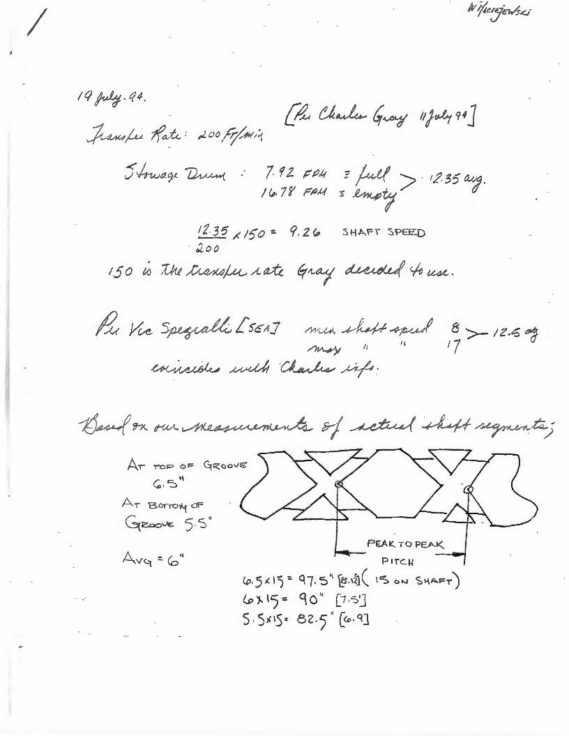
Wheels were fabricated from the same kind of material as the that of the actual Level Winder Shafts, Ni-Al-Br. These Shafts were supported on an axle and rotated at a speed that matched the operating speed of the actual Level Winder System, approximately six (6) revolutions per minute (rpm). The calculations for this speed (which may be found in Appendix B) were based on information provided by Mr. C. Gray (Code 4221). Also included in Appendix Bare calculation regarding placement of the 84-pound (lb.) applied load.

TM941159
The width of the contact area of the wheels was based on the approximate contact area of the Pawl. It appeared that about .20 inch (in.) of the curved tang on the Pawl made contact with the side land of the Shaft groove. The width of the contact area varied, since the tang is a curved surface. The experimental wheels were designed with a contact surface of about . 25".
A pan was placed under the wheels and filled with artificial seawater. A circulating pump was set up to provide a continuous water bath which was directed to the contact point between the wheel and test sample.
Figures 5 and 6 are photographs of the actual machine used to conduct the test. A large motor was set up on a table, and an axle assembly was devised and outfitted with a set of bearings and supports. The wheels were bored out to fit the shaft, and aluminum collars were fabricated to it. A mechanical cycle counter was connected to the shaft to provide a continuous readout of elapsed cycles.
Another bracket was constructed with a hinge and a piece of steel channel that would pivot above the wheels. On this channel rested an 84-lb. weight. Use of the channel provided the apparatus with the ability to adjust the actual load experienced by the test samples.
The samples, themselves, were made by obtaining a piece of the respective test material, drilling a 1/4-20 hole in the center of one (1) side and bolting it to the under side of the channel. It is this free surface that was being wear tested and it was, therefore, imperative that the free surface of this test sample have the desired surface finish to be tested. As depicted in the Figures, it was designed to run two (2) samples concurrently.
Four (4) of the materials that were tested were weld-clad metals on a substrate of 1040 mild steel. The claddings were Stellite, Inconel 625, Monel, and a Stainless. These clad samples had been used for some previous corrosion and hardness experiments; their condition, however, was excellent. There were no signs of corrosion, and the surfaces were a ground finish of approximately 63 to 125 microinches {}Lin). The indentations from the hardness tests were located such that they did not interfere with this wear test.
Other materials that were tested included Inconel 625, Titanium, 304 Stainless, 316 Stainless, and Ni-Al-Br. All of these samples were cut from bar stock and both ends were faced off on a lathe and maintained a surface finish of approximately 63 J.Lin.
As alluded to in earlier discussions, different coating process and wear-resistant materials were being investigated. While many of these could prove beneficial to this project, none could be obtained in a timely or economical manner. However, two (2) samples, Inconel 625 and 3116 Stainless, were giyen a special coating of Tungsten Carbide, in a process called "Rocklinizing" which is electronically deposited to approximately .002" of thickness. Small areas on each of the sample surfaces were prepared and tested. This process was included because the vendor offered it for experimentation.
2

TM941159
EXPERIMENTAL TECHNIQUE
With the aforementioned apparatus, the outside diameter (OD) of each wheel was measured and recorded prior to the start of a test. The samples were inspected and mounted under the channel. The motor and water pump were then started; and the channel, with the sample and weights, were brought in contact with the wheels. Once contact was made and the experiment was underway, the cycle counter was zeroed. At this point, the experiment was underway.
A test life of approximately 60,000 cycles was equated to 9.5 array deployment/retrieval cycles. This was based on an array length of 5,000 feet. In the context of this TM, An array cycle is being considered one (1) deployment or one (1) retrieval. Appendix B includes the calculations that support these values. This array deployment/retrieval life was an arbitrary selection, based on the time constraints imposed on the testing.
During testing, the samples were inspected several times a day for signs of degradation to either the sample or the wheels. If wear was observed, it was noted. If severe wear was observed, the sample was removed from the test. The second sample was not effected by the removal of one (1) sample, the test continued.
Once a sample was removed, the wear on both the sample and associated wheel was microscopically examined and photographed, the number of cycles logged and the OD of the wheel was measured and recorded.
Once a sample is removed from the test, it remains available for further examination--if necessary. The wheel, however, is machined, remeasured and made available for the next test.
This procedure was followed throughout the testing for each sample material and wheel combination.
TEST RESULTS
The results of the Wear Test are summarized in Tables 1 and 2 and Figures 7 through 31. The evaluation information consists of measurement of the wear surfaces, dimension changes, visual observations and surface comparisons.
The Tables provide a quick-look view of the materials, test cycles, dimensional changes, and a condition rating. No sample actually failed this experiment. The samples that have 59,000 or more cycles were stopped for time constraints. Samples that lasted for shorter cycle spans were discontinued because it was the opinion of the author that the damage was severe enough to warrant their elimination from further consideration. These decisions are strictly arbitrary, based on physical evidence and limited knowledge of the Handling System.
The Condition Rating that is presented is based on a visual inspection of the test materials and the wheels. It is a comparison of the actual surfaces (or a photograph of the surface) against a GAR S-22 Microfinish Comparator. The choices were narrowed from 22 finishes, to three (3), with a fourth category, galling, added because of the Monel test. The larger the rating
3

TM941159
number, the smoother the surface. In the legend that accompanies the tables, the "ST" designation indicates that the fmishes were compared to shaped/turned finishes.
The dimensions measured for the wear damage included: the width, measured perpendicular to wheel rotation; the length, measured parallel to the wheel rotation; and , the depth, measured into the thickness of the material. Because the contact surface of the wheel was about .250" wide, most of the numbers are between .21" and .28", depending upon how the load compressed the test samples. Most of the samples did not wear in straight lines; instead, they wore in a trapezoidal shape. The length measurements are measured as a chord, across the top surface of the material. The depth is measured at the deepest part of the damage area.
In Table 2, along with the Cycles and Condition Rating, the Wheel Diameter Change is presented. This number is based on measurements of the outside diameter of the wheel before and after testing. After a test, the wheels were measured, inspected and photographed, then redressed for the next test. Redressing consisted of turning the test section on a lathe to obtain a smooth surface (about a 63 JJ.in). Naturally, as the testing progressed through different material candidates, the diameter of the wheels became smaller.
Figures 7 through 14 depict the weld-clad samples and the wheel surfaces that were in contact with them. On Figures 9 and 10, the galling of the Monel is visible. As noted, this occurred in a relatively short period of time. Although there is no photograph available to support the appearance of the wheel, it, too, showed similar wear characteristics. On both parts, it appeared that metal had been peened over, it was shiny and rough to the touch. Figures 21 and 22 show the Titanium sample and wheel, respectively. The wheel used shows similar rough characteristics, but, the Titanium sample itself, does not.
Figures 23, 24, 25 and 26 show the behavior of the Ni-Al-Br Pawl material in this test. the sample used was fabricated from and actual Pawl. Of all the samples tested, it showed the highest degree of wear.
Figures 27 through 31 characterize the behavior of the Rocklinized samples. Each of the base materials was coated with approximately .002" of the carbide coating which was worn through. This coating was applied to the base metals cold; further information is contained in Appendix C.
CONCLUSIONS
It is the opinion of the author that very careful consideration should be given to the test data that has been presented. While care was taken to duplicate service conditions, this was an experimental set-up, with design, fabrication and testing accomplished in a very short time period. It is important to realize that it was an experiment and there may be some facet of service operation that was inadvertently overlooked which could render even the best material ineffective.
Due to the time constraint imposed, several options were not thoroughly investigated. They should, however, probably be considered for future applications. these include various wear-resistant coatings, thermal spraying, and the use of special inserts.
4

TM941159
Based on the testing and observations discussed herein, it seems that Inconel 625 bar stock is the best choice, both mechanically and economically. While both the cladding and bar forms indicate consistent and damage-tolerant behavior, weld cladding can be a labor-intensive operation adding cost to the part. Inconel 625, while extremely resistant to corrosion, is very strong mechanically and is readily available in bar form from local suppliers.
Figure 32 represents the existing Pawl material and the Inconel 625 bar test sample. It becomes readily apparent why Inconel is being recommended as the replacement material. The comparison is one (1) of severe wear and material degradation versus virtually no significant damage.
The reader is, again, reminded that these materials were selected because they were readily available and there was a time constraint imposed. Further testing under actual service conditions is highly recommended. It is entirely possible that the lnconel 625, while performing well under these artificial conditions, could behave poorly when it is subjected to a higher number of cycles.
5

Do Not Scale Drawing
C71500 Cu-Ni Level Winder Shaft
@ C63000 Aluminum-Nickel-Bronze Pawl

TM 941159
Figure 2. Pawl Wear
7

TM 941159
Figure 3. Shaft Wear
8

Candidate Pawl Material
Shaft Material (NI-AI-Br) _ ___ ...,,
Applied Load
0
TM 941159
----j r-- Approximate Contact Surface
Wear-Testing Apparatus Schematic
Figure 4. Wear Testing Apparatus Schematic .
9

TM 941159
Figure 5. Wear Testing Apparatus Photograph A
10

TM 941159
Figure 6. Wear Testing Apparatus Photograph~
11

TM 941159
-. . .,-.. , ... : ' . J
Figure 7. Clad Inconel 625 (lOX)
Figure 8. C71500 Copper-Nickel Wheel/ Clad Inconel 625 (lOX)
12

TM 941159
Figure 9. Clad Monel (lOX)
Figure 10. Clad Monel (5X)
13

TM 941159
Figure 11. Clad Stainless (S.SX)
...
Figure 12. C71500 Copper-Nickel Wheel/ Clad Stainless (11.25X)
14

TM 941159
Figure 13. Clad Stellite (0.8X)
Figure 14. C71500 Copper-Nickel Wheel/ Clad Stellite (lOX)
15

TM 941159
. ...,~
Figure 15. 304 Stainless (6X)
...
Figure 16. C71500 Copper-Nickel Wheel/ 304 Stainless (lOX)
16
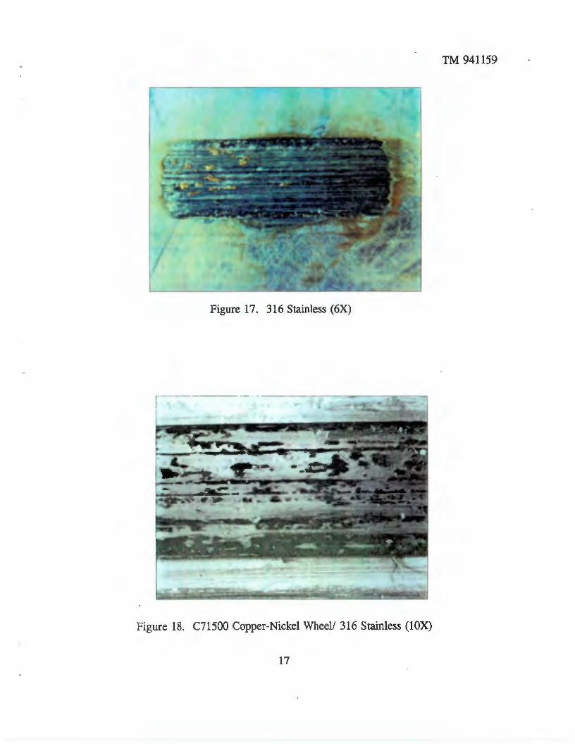
Figure 17. 316 Stainless ( 6X)
Figure 18. C71500 Copper-Nickel Wheel/ 316 Stainless (lOX)
17
TM 941159

TM 941159
Figure 19. Inconel 625 Bar (lOX)
Figure 20. C71500 Copper-Nickel Wheel/ lnconel 625 ~ar (lOX)
18

TM 941159
L: • . • ~ • 1
• ,I .. ~
...J
Figure 21. Titanium Bar ( 1 OX)
Figure 22. C71500 Copper-Nickel Wheel/ Titanium Bar (lOX)
19

TM 941159
Figure 23. C63000 Nickel-Aluminum-Bronze (Pawl Material, lOX)
Figure 24. C63000 Nickel-Aluminum-Bronze (Pawl Material, 2.5X)
20

TM 941159
L Figure 25. C71500 Copper-Nickel Wheel/ C63000 Nickel-Aluminum-Bronze (2.5X)
Figure 26. C71500 Copper-Nickel Wheel! C63000 Nickel-Aluminum-Bronze (15X)
21

TM 941159
Figure 27. Rocklinized Samples
22

TM 941159
Figure 28. Rocklinized Stainless (lOX)
--------~------------------- --
Figure 29. C71500 Copper-Nickel WheeV Rocklinized 316 ~tainless (lOX)
23

TM 941159
Figure 30. Rocklinized Inconel 625 (lOX)
Figure 31. C71500 Copper-Nickel Wheel/ Rocklinized Inconel 625 (lOX)
24

TM 941159
Figure 32. C6300 Pawl Material and Inconel 625 Bar Test Comparison
25

1M 941159
Table 1. Level Winder Pawl Material Wear Test Summary
Material Cycles Condition Width Length Depth (Approximate) Rating • (in.) (in.) (in.)
Clad lnconel 625 59,400 4 .253 .275 .002
Clad Monel 128 1 .258 .309 Galled
Clad Stainless 65,500 2 .275 .464 .007
Clad Stellite 49,400 4 .251 .232 .0017
304 Stainless 60,000 2 .231 .615 .014
316 Stainless 60,000 3 .224 .611 .010
Inconel 625 60,000 4 .212 .210 .001
Titanium 55,000 3 .222 .552 .011
Nickel-Aluminum- 5670 4 .211 1.149 .055 Bronze (C63000)
Rocklinized 316 51,200 3 .219 .298 .004 Stainless
Rocklinized 51,200 4 .219 .268 .002 Inconel 625
* C~ndition Ratings: 1. Galled Surfaces 2. 250ST J.Lin 3. 125ST J.Lin 4. 63ST J.Lin
26

TM 941159
I Table 2. Level Winder Wheel Wear Test Summary I Material Cycles Condition Wheel Diameter
(Approximate) Rating • Change (in.)
Clad Inconel 625 59,400 4 .002
Clad Monel 128 1 0
Clad Stainless 65,500 3 0
Clad Stellite 59,400 3 0
304 Stainless 60,000 2 .001
316 Stainless 60,000 2 0
Inconel 625 60,000 3 0
Titanium 55,000 2 .0005
Nickel-Aluminum- 5670 3 .001 Bronze (C63000)
Rocklinized 316 51,200 3 0 Stainless
Rocklinized 51,200 3 0 Inconel 625
• Condition Ratings: 1. Galled Surfaces 2. 250ST p.in 3. 125ST p.in 4. 63ST p.in
27
1M 941159
REFERENCES
(a) NUWC Memorandum Ser 44211L/56, .. Hardness Testing of Towed Array Pawl and Shaft", dated 17 May 94, W. Maciejewski to C. Gray
28

Appendix A
Material Specifications
A-1
1M 941159

'
8
I
/R I D: 203-445-4.154 IWII:IIII~QII ... _..""" ..... ..., .... .,._
MF1Y 16 ' ·94 15:11 No.001 P.02
NOMINAL CHEMICAL COMPOSITION ·'"': .. ,· MECHANICAL PROPERTIES ., : , .. · . ... . , :
61 .0
Copper Nickel Iron Alloys AMPC0521 68.0
C98400
\~~~////;/ ll8.5 // /
/ / // //~ AMPCOG26 1;17.0
C06200
--AMPC0528 88.0 (:70600
AMPCO 570 71 .5 11.5 099300 . ..
Copper Tin Alloys AMPC061 87
092500
711 88.3 C90700
2 66.6
678
High copper All ovs AMPC092 ···t ·::, 11.5
AMPCO 114
AMPCOrn 96.5 Ct8200
AMPC087 CB11500
98.5
AMPC008 98.5 C1e200
........ , .... ... -·-- ....... , .. _ __, AMPC01110
' 99.75
-· AMPC0840t 96.5 018000 Iwrought} C$1640 ()41At)
AMP00945 96.6 (ptttent pending)
-· . AMPC0972 98.65
C18160 ~··-· ., .
0.5 30.0
0.5 30.0
t .5 10.0
1.5 10.0
0 .7 14.0
1.0
1.5
I r t.3
I 2.5
2.6 I !
2.5Pb HISI
33.0Zn
1.0Mn O.SSil 0.5
, 0.5Mni 0.5
1.0 Mn 0.151/ 0.5 0.5
1.5Coi 0.5
11.0 Sn 1.0Pb
12.0 0.:2 p
0.3
0.1Cr 8:6Si/
.!5 1.0Cr/ o.~
1.0 Crt 0.5
1.0Cr 0.5
U.15 i'ri' 0.10
0.6 Si 0 .4 Cr
60
50
45
45
ao " ·
40
65 55
65
47
·· ·-·-
95
... ... 0.6 Sl 0.4 Cr
1.10Cr 65 .12Zr
t AMI'CO 940 si/Q';' /9 pr0/6CI01d by pat~~nts •n thn bltowiflg oountr/98.' Unt~ Sr~tes, Austr~/ln. Austr~s. 88/gium, Canalis. FlntaM. F'Bn~M. ~91 Clerms~'l. Grsllf 8nt;Jin, 11aly, JB()Bf!, I<Df98.. Sp$•~. SWflrJen MCI SwiWifiBm1.
t:==", • .• I ::;(
go sa
76 48 55 12 15 126 153
66 32 l 37 20 28 140
55 20 23 30 ! 40 as,.. I 500Kg)
, . 50 25 30 20 2B 100
50 18 25 30 36 71 500 Kg)
85 50 53 \ 3 I 202 .. ~. . ..
45 24 25
55 26 30
28 32
32
Hardness HRB
70 30 33 2 3 00 93
65 35 45 10 15 70 78
72 60 65 13 16 75 62
61 35 40 13 17 65 68
65 61 19 65 TO
' "62~ ~- 60 16 65 70
100 70 75 9 13 90 94
-~
132 72 8 30 32 HAC HRC
- · · 75 70 13 15 84
• ~h•n.le•l prOf'~tflos ~,... ba~tM on 1881 liar v~IU<1S (1( ' ' 1'0/,JnC$ wllare llPPiiCdbiB.
0.323
v ~ 0.323
0.323
0.323 .
0.269 I
I • • • 0
0.316
0 . ..,14
0.316
0.315
0.265
0.320
0.320
0.320
0.3~0
0.321
0.315 .. M10
0.320
-·-

...,
ID:203-445-4154 MH'I 11 ':::'~ ':::'•UO I"~U .1.-'lJ.l r .UL
Aluminum Bronzes
ALLOY/ U~S NUMBER
AMPCOC·3 096400
AMPCO C·3HT 095400HT
,----1
I Copp&r
BS
85
NOMINAL CHI!MICAL COMPOSITION
---~---l-~-----r·-~ T~;~jj;- .. Yletd-'fl~rJ]a· 1 I Strength Strength lion ; (K81) (KSI) (%)
Other Aluminum Iron Nickel (Max.) Min. Typ. Min. _'!YP· Min. Typ.
10.5 4.0 25 0.5Mnl 75 62 30 34 12 14 (Max.) 0.5 ·
4.0 10.5 2 .5 0.5Mni (Max.) 0.5
90 95 45 47 6 , 0 180 192 0.269
-----··+-:::~-+----:-::-----1f-~-+-~-+---:--l-,.-:---i--:--:-+-:-t---,---4-~-+--+...,....,+--+-----1 AMPCO D-4 79.5 10 5 5 0.5 90 95 40 43 10 12 170 187 0.270
CD5500
------+----·---J~-----+---::---t----::----1r----::-:--+~+~+-=-=-+~+--:--+--··+-=-:-::-~~~-----J AMPCO D-4HT 795 10 5 5 0.5 110 115 60 65 10 14 216 228 0.270 I
C95110HT
AMPCOM-4+ CDISIS20
77.6 11 4.8 !U 1.0Mfll 125 130 0.5
I
I ., .. I
95 105 2 (At 0 .2%
Otf$$1)
4 255 269 0269
i
----~----~--~~-+--------+-~:--~~--4-----~~-+--~-~--~--4---+---+---~----~ AMPCO M·4-t- 77.6 11 4.8 5.1 1.0 Mn/ 135 145 100 116 6 262 296
C83020 8
0.6 (AI0.2% otf&et)
0.269
1.0Mni 110 116 68 75 10 15 202 228 o.s
;·~lJ~A~M~~P~c9-~o-4-5~--·.+ .. ~a~o~.o-- .. ·---1-o~.o~-4--~3~~+-~s.~o--+-~~~r-~~~~~~~~~~~~~~~~~~ ~ ,e~oo / .
/ j /1 'A...,PCO 4Bf-.. .c. -+--8-1 .. --+----:--9 --t---4:---:. 0:--'t---4~.5-::------t--,-.:. O~M::-n-,-i --+~8~5-+--:9~2+--::-375 -t-739
0.212
18 15~ 17<t 0.276 Cil5800 I 0.5
AMPCO 483 81 9 95 105 50 53 16 22 212 0.276 063200
AMPCO 496 75 8.0 ----4---------~--~~----~--~--~~~~~~r-~---~--~~~--~--~~ 92 9E. 42 48 22 28 160 180 0 .273
C85700 . AMPC0&42 90.5 7
C84200
.. :~;::~~~~,~ · · . . ~ .. Manganese Bronzes . ~ .. ,;111 4( o ' I
,. ~; : ' . • I
.. •'~":"
: · . '. ·.' '•
.•.
~ t.f . - :.~!<-::_, ,; . . ~ •: .. ·.: ',. '
~~-:: ·. ~·
ALLOY I UN& NUMIER
; {~
AMPC082 081500
..
AMPC064 ; C88200 ~·-~-~~- ,, .. , . AMPCOII . ; 018300 . t• •t. • .
::; ;;;~ '
..
Copper Aluminum Iron ~lc:kel
59.0 1.0 .. 1.0 .. ... \i . ~. ·"' ..... :·
64.0 4.0;· 3_.0 . ~ ~ . ;. :~ : -~· .. . ~
: .. ': ' ,·•. ~
-t U.S Patenl N(l 3.376.413 · ·• ·'. ji, . • ,.· : .;-:· ..
62.0 . ' 6.0 .... ;·. \ . 3.0 .. ; .·. l~· .. ·:, .•'• .. ,,. r··
· .\:Y!i~~ ~-,,
.. ··. :J 'i
- ;;~:~J .. J=A : ~ ... _:·~~r~·. '·
(AI0.2% a_a 1. a .. o 1. 44 53
otlsel)
Ten•lle Yield
Other
Stren8th (KB .
Strenftlh (KS)
(Max.) Min. Typ. Min. Typ. 0.3Mn 65 72 25 28 3~.5 Zn
3.5Mn 90 95 45 48 25.5Zn
3.5Mn 110 115 60 85 25.521'1
i-t_.. 2 •Mechan•c•l /lrOJJr~ffH!s .,.. a.:~ .a Ott INf bM v~u•r ()1 I" rr.>ultd5 wllel'l!' appll.:•bllf
15 30
Elong•· tlon (%)
Min. Typ. 25 35
20 25
12 15
130" 165 (100, Kg)
Hardn••• BHN
3000Kg.
Min. Typ. 112 131
170 192
192 2Z3
0.278
Den1Jty Lb/Cu.ln.
0.296
0.289
0.284
~ ~ 69~

Appendix B
Calculations
B-1
1M ~1159
I
IQ~.t(4.
:/t~~ ~ ah. : ,Loo ;'~~1
Jlrw"-cr ~ : 1 r z t:~'4 : futt >. tL-36 a.vg. ;t,. 7»' r/JM t ~, d
IZ.35 ;(ISO : q, 2 (p SHA.FI SPEED
· Joo
150 ~ 'J)u ~~A-a.tl trA.-ay ~ ~ tL4(,,
Ar TOP oF ~~Qove
~.-s''
A, serro"'f c:tr
~i!.oov'& 5. s"
A -/ .. v~ - 1.0
PEAK. TO PEAK,. .......__ -~
P lTC.~
(p.)l( I):. C\7. 5'' ~.\t}( \S ~"" ~~AF=TJ (p ..,. \ '5 ~ q 0 II [ 7 ''S J s.s)(lss 82-5~ c~ · ct]

a,tZfq.z~ = 7. '5/ q.zC;, = Gt. ql q.z.GtJ =
. 877 MIN I '8otf MIN
1 74 5 ~)It/
; ; .., Ml tJ To <:.o MP1..Ut:: i e.li:V Oi....U'i\ o~ '.i:ii,.J
~ ~ ~ ~ ~ 9.3 Frj!f;l'() d ~ sooo FT _ 5 3J·CP ,/./;/'/ = 8, Cfc, H'f ro t:t::Pi-0/"
Cf._3 F/{,r1N tfi/11 IU<R4r:
CoNrfic.-r llzcli ol'l RwL. , ~ X , Z ~ , ~ 1/11 2 suR~Ac~
~d ~ ~ c:f ~/)a.-vi- A;U.,a.--~-~.
84 I b load
~------~-------~,
m ( rnom,f'lC.)
t 84 I'"' ( d-es1rc:d /oa<t)
vJ (A:ppl ~d 1 oa d o:t-fti:k.. ~~.Ill d~Y ~\.)""\ 1
~Ft~o ~H~so

/
~
-N~ coaoco ., Ml")M ~
~~~i
-
• . t
~' ' I
J :1-~ 1. L--~7 da ~ ~/ {; .. ~- I .
' 1
C= 7id -=- 4. 8 '1 = ~ 4 # .
~ ~~.6~~ ~ r1,2& pjJJ)
I H v := 4 z I/ ::- 4 j../-
. : I /'J.-lj ~ /. & ;-1-
1~2~ --I (y .~
5., 79 .!: (p rev ~ ouiC \ (if I I) ~~·.:::---~ '
-M;N ::: rev --1£v NJN

~~"' ww~ www :1::1::1:
"'~"' 000 ,.,~~
.-NO. ~ GOGOQ):l ..,..,..,~
NNN ~ ................
·-
-... Fo1? o ' \

Appendix C
Rocklinizing Data Sheet
C-1
1M ~1159

.;-
~~ LJbJ
~ ·;, ,
(;' ~c· -:.
"' j ~
KNIVES & SHEARS
~ DRILLS
. -
_ . ...,...-~: .
~
(r
# ' -/
/ -' · -/ /~ TAPS
:~:~ ~
' ..... - ~-""
~·
F1 "------'"'
CHASERS .
T~ ~ROCKLINIZER electronically applie> electrode material by a:spark'dei)oSition ··process; · MateriaJ is i(llpregnated bot~ un~e.rnea.th ari,d ()11 top of tb~ wp,r~Ri.~~~ s~rf~f~· ~~~u~~no:~lPP~~ia_~!~. ~:~~ti~ g_ener~t~1
the temp~r <?ithe wo~kpleCeJS{etalnep.· R9.~~~~~?.Jff:;9 ,Is .~PB.t.~e_d to ne~p~reg~~nd anq_[~~:hf,rp~~~? ~rfq,c~s. ~-. ~ . . . ·;: .' -· ' ~~ ......... ; ' ·. . '.
Punchini~tamping,:Forgirig ~ri(J:EXIr~iding:· 5top slug :p~li back, reduce· gaHing,_.exte~d tirne between·sharpenings·,: ·: oie'·c~«r~g~ R~store parting tines, p'reve~t-heatcheckrrJg) . sgfde,r,ing,..·~izing of cores, protect'gates and runners ·
•• _.- .•• ; .... ·-~- - . -~- <t....-~ - _ - :!!'-i:!_'r::- .J_';~- .. :: • .. ··~~~·o+_ \-t.-:~ · -,~~-'""- -
Gripping and Screw -~~thi~ing:{i:.e: be~ding·~~mP.S:>' collets, pusher padstfu€d'fingers,/c~uck: jaws}froViqe~t suitable textured finish and~e·tolerance:s::
.. ... . .t.... ,:::- ... . \ : •
Perishable Tools iuuf.DieS:; Reduce wear on high speed_ steel and :carbide too_ting ~~: · · · ' ··
Maintenance: Restore toferances on bearing's;. shafts, and other wear areas
Solid Carbides and Inserts: Surface seal and prevent chipping Plastics and Composites: Improve fabrication operations including molding, machining, trimming, and protecting abrasive wear areas Glass Processing: Molds, &it=bfh,99lihSi glass handling equipment · .... · ·. ,.·
. . . ,. . . . ;.:
Wood Industry: Saws, ·~r5; p~~r -blades; ~d chipper knives · "' ·· · · · · ·
Paper Products: Die cUtting knives arid shear bfa~